JP6619896B1 - Scent display - Google Patents
Scent displayDownload PDFInfo
- Publication number
- JP6619896B1 JP6619896B1JP2019029388AJP2019029388AJP6619896B1JP 6619896 B1JP6619896 B1JP 6619896B1JP 2019029388 AJP2019029388 AJP 2019029388AJP 2019029388 AJP2019029388 AJP 2019029388AJP 6619896 B1JP6619896 B1JP 6619896B1
- Authority
- JP
- Japan
- Prior art keywords
- scent
- cartridge
- guide member
- cartridges
- cartridge housing
- Prior art date
- Legal status (The legal status is an assumption and is not a legal conclusion. Google has not performed a legal analysis and makes no representation as to the accuracy of the status listed.)
- Active
Links
- 238000010248power generationMethods0.000claimsdescription2
- 238000005192partitionMethods0.000description26
- 239000003205fragranceSubstances0.000description20
- 230000000694effectsEffects0.000description14
- 238000004891communicationMethods0.000description7
- 238000002347injectionMethods0.000description6
- 239000007924injectionSubstances0.000description6
- 239000002304perfumeSubstances0.000description6
- 230000007246mechanismEffects0.000description5
- 210000000078clawAnatomy0.000description4
- 230000006870functionEffects0.000description4
- 230000007423decreaseEffects0.000description3
- 239000002184metalSubstances0.000description3
- 238000000034methodMethods0.000description3
- 230000002093peripheral effectEffects0.000description2
- 230000008786sensory perception of smellEffects0.000description2
- 230000008901benefitEffects0.000description1
- 230000008878couplingEffects0.000description1
- 238000010168coupling processMethods0.000description1
- 238000005859coupling reactionMethods0.000description1
- 230000006872improvementEffects0.000description1
- 238000012423maintenanceMethods0.000description1
- 238000004519manufacturing processMethods0.000description1
- 238000012986modificationMethods0.000description1
- 230000004048modificationEffects0.000description1
- 230000000149penetrating effectEffects0.000description1
- 238000000638solvent extractionMethods0.000description1
- 238000005507sprayingMethods0.000description1
- 239000000758substrateSubstances0.000description1
- 230000000007visual effectEffects0.000description1
Images


Landscapes
- User Interface Of Digital Computer (AREA)
- Disinfection, Sterilisation Or Deodorisation Of Air (AREA)
Abstract
Translated fromJapaneseDescription
Translated fromJapaneseこの発明は香りディスプレイに関し、特に複数の香りカートリッジを装填し様々な香りを噴射可能な香りディスプレイの改良に関する。 The present invention relates to a scent display, and more particularly to an improvement of a scent display in which a plurality of scent cartridges are loaded and various scents can be ejected.
人間のコミュニケーションには、人間の持つ感覚に応じた様々なモードがある。これらの中で最もよく使用されているのは、視覚及び聴覚を用いたコミュニケーションである。これに対し、嗅覚は人間の生活では比較的よく使用されているにもかかわらず、これをコミュニケーションに使用している例は極めて少ない。しかし、コミュニケーションで視覚及び聴覚に加えて嗅覚まで利用できるようになれば、コミュニケーションはより効率的になり、様々な人がより深く体験を共有できるようになると考えられる。 There are various modes of human communication according to human senses. The most commonly used of these is visual and auditory communication. On the other hand, although olfaction is used relatively often in human life, there are very few examples of using it for communication. However, if it becomes possible to use olfaction in addition to vision and hearing in communication, communication will become more efficient and various people will be able to share experiences deeper.
こうした点に着目して、最近では、テレビジョン受像機、パーソナルコンピュータ、ゲーム機等、映像と音声とを再生できる装置に接続して使用され、場面にあわせて香りを発生する装置が提案されている。この明細書では、そのように場面にあわせて香りを発生する装置を香りディスプレイという。 Focusing on these points, devices that generate scents according to the scene have been proposed recently, which are used in connection with devices that can reproduce video and audio, such as television receivers, personal computers, and game machines. Yes. In this specification, such a device that generates a scent according to the scene is called a scent display.
場面にあわせて香りを発生する場合、直前に発生した香りが残っていると十分な効果が期待できない。そこで、任意の時点で、ある限られた範囲に所望の香りを放散させ、任意の時点でその香りを消して次の香りに切替えることができるような香りディスプレイが望ましい。 When generating a scent according to the scene, if the scent generated immediately before remains, a sufficient effect cannot be expected. Therefore, a scent display is desired in which a desired scent can be diffused to a limited range at any time, and the scent can be turned off and switched to the next scent at any time.
したがって、こうした香りディスプレイでは、複数の香りを自由に切替える機能を持たなければ十分に香りを活かすことができない。そこで、それぞれ予め選択された香りの発生源(これを「香源」という)を封入した複数のカートリッジ(これを「香りカートリッジ」という)を準備し、これを香りディスプレイに装填し、所望の香りカートリッジから香りを発散させることが考えられる。 Therefore, in such a scent display, the scent cannot be fully utilized unless it has a function of freely switching a plurality of scents. Therefore, a plurality of cartridges (this are called “scent cartridges”) each enclosing a preselected scent generation source (this is called “scent source”) are prepared, loaded into a scent display, and a desired scent is prepared. It is conceivable to emit scent from the cartridge.
香りカートリッジには内部の香源からの香りを外部に噴出する香り通路を設け、所望のタイミングで香りカートリッジ内部に空気を送り込む機構を香りディスプレイ側に設けることで、香り通路を通して外部に香りが噴射される。それに合わせて香りカートリッジの香り通路の近くに噴出口を持つ、香り成分を含まない空気だけを噴出する空気の噴出機構を設ける。ある香りを射噴した後、次の香りに切替えるときには、この空気の噴出機構から空気を噴射して周囲の香りを含んだ空気だけを吹き払い、その後に次の香りを噴射する。こうすることで任意のタイミングで香りが混ざることなく香りを切替えることができる。 The scent cartridge is provided with a scent passage that ejects the scent from the internal scent source to the outside, and a mechanism that sends air into the scent cartridge at the desired timing is provided on the scent display side so that the scent is jetted through the scent passage Is done. Correspondingly, an air ejection mechanism is provided which has an ejection port near the scent passage of the scent cartridge and ejects only air containing no scent component. When switching to the next scent after spraying a certain scent, only the air containing the surrounding scent is blown off from this air ejection mechanism, and then the next scent is ejected. By carrying out like this, a fragrance can be switched without mixing a fragrance at arbitrary timings.
こうした技術が後掲の特許文献1に開示されている。特許文献1に開示された技術は概略上記したとおりである。ただし、香りディスプレイの筐体には外部への香り等の噴射のための開口が形成されており、各香りカートリッジの香り通路と、空気の噴出口とがいずれもこの開口につながっている。各香りカートリッジは香りディスプレイの筐体に着脱可能な形で装填される。各香りカートリッジの所定部には、空気を香りカートリッジ内部に送り込むための給気口が形成されている。香りディスプレイに香りカートリッジが装填されたときに、香りディスプレイ側でこの給気口に相対する部分には、圧電素子を取り付けたダイアフラムを内蔵する風力源が各香りカートリッジに対応する形で内蔵されている。この圧電素子に交流電圧を印加すると、ダイアフラムが振動し、風力源に設けられたノズルと香りカートリッジの給気口を介して香りカートリッジ内部に空気を送り込む。空気が送り込まれた香りカートリッジからは、内部の香源に応じた香りを含む空気が香り通路を通じて外部に噴出される。 Such a technique is disclosed in Patent Document 1 described later. The technique disclosed in Patent Document 1 is generally as described above. However, an opening for ejecting scent or the like to the outside is formed in the casing of the scent display, and the scent passage of each scent cartridge and the air outlet are both connected to this opening. Each scent cartridge is detachably loaded in the scent display housing. An air supply port for sending air into the scent cartridge is formed in a predetermined portion of each scent cartridge. When a scent cartridge is loaded in the scent display, a wind source with a built-in diaphragm with a piezoelectric element is built in the part corresponding to each scent cartridge on the part of the scent display facing the air supply port. Yes. When an AC voltage is applied to the piezoelectric element, the diaphragm vibrates, and air is sent into the scent cartridge through the nozzle provided in the wind power source and the air supply port of the scent cartridge. From the scent cartridge into which air is sent, air containing a scent corresponding to the internal scent source is ejected to the outside through the scent passage.
また、香りカートリッジとはつながっていない空気の噴出口を形成する空気の通路の他端には、香りカートリッジのためのものと同様の原理で、かつ香りカートリッジのものよりも大型の風力源が設けられている。この風力源の圧電素子に交流電圧を印加することで空気の噴出口から香り成分を含まない空気の流れが噴射され、近傍の香りを消散させる。 Also, the other end of the air passage that forms an air outlet that is not connected to the scent cartridge is provided with the same principle as that for the scent cartridge and a larger wind power source than that of the scent cartridge. It has been. By applying an AC voltage to the piezoelectric element of the wind power source, an air flow that does not contain a scent component is ejected from the air outlet and dissipates the nearby scent.
上記したような構成を持つ香りディスプレイによれば、どの風力源を動作させるかによって香りを自由に切替えることができる。またその際に香りを含まない空気の放出機構を適宜動作させれば香りが混ざることを防止できる。どの風力源をどのタイミングで動作させるかについては、外部から香りディスプレイにコマンドを送ることで制御できる。そのため、例えば映画、アニメーション等で所望のタイミングで所望の風力源を動作させることで、場面にあった香りを噴射できるという優れた効果がある。 According to the scent display having the above-described configuration, the scent can be freely switched depending on which wind source is operated. In this case, the scent can be prevented from being mixed by appropriately operating an air release mechanism that does not contain the scent. Which wind source is operated at which timing can be controlled by sending a command to the scent display from the outside. Therefore, for example, by operating a desired wind source at a desired timing in movies, animations, etc., there is an excellent effect that a scent suitable for the scene can be ejected.
しかし、特許文献1により提案された香りディスプレイを用いて香水のサンプルの香りを噴射させる場合、ある香水の香りを噴射した後、空気流で消散させ、別の香水の香りを噴射すると、前の香水の香りが完全には消散されていない場合があることが判明した。このため、別々の香水の香りが混ざってしまうと、香水のサンプルのディスプレイとしての機能が半減してしまうという問題がある。 However, when injecting the scent of the perfume sample using the scent display proposed by Patent Document 1, after injecting the scent of one perfume, dissipating it with the air flow, and injecting the scent of another perfume, It has been found that the perfume scent may not be completely dissipated. For this reason, when the fragrances of different perfumes are mixed, there is a problem that the function of the perfume sample as a display is halved.
また、複数個の香りカートリッジが密に装填されるため、香りカートリッジが簡単には取り外せず、香りカートリッジの交換に手間がかかるという問題もあった。香りディスプレイで様々な香りを放散させるためには、カートリッジの交換が容易であることが望ましい。 In addition, since a plurality of scent cartridges are densely loaded, there is a problem that the scent cartridge cannot be easily removed, and it takes time to replace the scent cartridge. In order to dissipate various scents on the scent display, it is desirable that the cartridge can be easily replaced.
それ故にこの発明の目的は、香りカートリッジから噴出された香りを必要なときに確実に消散させられる香りディスプレイを提供することである。 Therefore, an object of the present invention is to provide a scent display that can reliably dissipate the scent ejected from the scent cartridge when necessary.
この発明の他の目的は、香りカートリッジから噴出された香りを必要なときに確実に消散させられ、かつ香りカートリッジの交換が容易な香りディスプレイを提供することである。 Another object of the present invention is to provide a scent display in which the scent ejected from the scent cartridge is surely dissipated when necessary and the scent cartridge can be easily replaced.
この発明のさらに他の目的は、香りカートリッジの交換が容易な香りディスプレイを提供することである。 Still another object of the present invention is to provide a scent display in which a scent cartridge can be easily replaced.
本発明の第1の局面に係る香りディスプレイは、各々が内部に香源を収容し、一定の立体形状を持つ複数個の香りカートリッジを収容するカートリッジ収容筐体を含み、各香りカートリッジから香気を筐体の外部に噴射する香りディスプレイであって、香りカートリッジは、互いに対向する第1の面及び第2の面と、第1の面の第1の端点と第2の面の第1の端点とを接続する、少なくとも1つのエッジを持つ第3の面とを持つ中空の柱状体であり、かつ、第1の面の第1の端点の近傍には、柱状体の内部の空間と通じ、内部の空間からの香気を含む空気を噴出する噴出口が形成されており、カートリッジ収容筐体は、第1の端部及び第2の端部を持ち、香りディスプレイは、カートリッジ収容筐体の第2の端部側に設けられ、駆動信号に応答して動作するファンと、カートリッジ収容筐体の第1の端部側にカートリッジ収容筐体を覆うように取り付けられ、かつ中央に開口部を有するトップパネルと、を含み、カートリッジ収容筐体の内部には、ファンからの空気流をトップパネルの開口部に導くように筒状のガイド部材が設けられ、当該ガイド部材により、カートリッジ収容筐体は、ガイド部材内部と、ガイド部材外部であって複数個の香りカートリッジが収容されるカートリッジ収容部とに分割され、トップパネルは、開口部を内側開口部と外側開口部とに分離する第1の部材と、開口部の外周を規定する第2の部材とを含み、内側開口部はガイド部材内部に通じ、カートリッジ収容部は、ガイド部材を中心として、第1の面がトップパネル側を向くように、かつ噴出口がガイド部材側に位置するように複数個の香りカートリッジを収容し、カートリッジ収容部に収容された複数個の香りカートリッジは、いずれも、その噴出口が外側開口部に対向する位置に配置され、香りディスプレイはさらに、カートリッジ収容部内に、複数個の香りカートリッジに対応して設けられ、それぞれの駆動信号により制御されて、それぞれの香りカートリッジ内の香気を含む空気を香りディスプレイ外に噴射させる噴射駆動部を含む。 The scent display according to the first aspect of the present invention includes a cartridge housing housing each housing a scent source, and housing a plurality of scent cartridges having a certain three-dimensional shape, and scents from each scent cartridge. A scent display sprayed to the outside of a housing, wherein the scent cartridge has a first surface and a second surface facing each other, a first end point of the first surface, and a first end point of the second surface. A hollow columnar body having a third surface having at least one edge, and in the vicinity of the first end point of the first surface, communicated with the space inside the columnar body, An outlet for ejecting air containing fragrance from the internal space is formed, the cartridge housing case has a first end and a second end, and the scent display is the first of the cartridge housing case. 2 is provided on the end side and responds to the drive signal. And a top panel attached to the first end side of the cartridge housing case so as to cover the cartridge housing case and having an opening in the center. Is provided with a cylindrical guide member so as to guide the air flow from the fan to the opening of the top panel, and by the guide member, the cartridge housing case is provided inside the guide member and outside the guide member. The top panel is divided into a cartridge housing portion in which a single scent cartridge is housed, and a top panel separates the opening into an inner opening and an outer opening, and a second member that defines the outer periphery of the opening. And the inner opening communicates with the inside of the guide member, and the cartridge housing portion has the guide surface as a center, the first surface faces the top panel side, and the jet outlet is a A plurality of scent cartridges are accommodated so as to be located on the side of the door member, and each of the plurality of scent cartridges accommodated in the cartridge accommodating portion is disposed at a position where the jet port faces the outer opening, The display is further provided in the cartridge housing portion corresponding to the plurality of scent cartridges, and controlled by the respective drive signals to eject the air containing the scent in each scent cartridge outside the scent display. including.
好ましくは、カートリッジ収容筐体とトップパネルとは、複数個の香りカートリッジの各々の噴出口と外側開口部とが通じる部分の周囲が気密となるように互いに組み付けられている。 Preferably, the cartridge housing case and the top panel are assembled with each other so that the periphery of the portion where each of the plurality of scent cartridges communicates with the spout and the outer opening is airtight.
より好ましくは、開口部の、カートリッジ収容筐体の側である第1の端部の内径は、カートリッジ収容筐体と反対側の第2の端部の内径よりも大きい。 More preferably, the inner diameter of the first end portion on the cartridge housing side of the opening is larger than the inner diameter of the second end portion on the side opposite to the cartridge housing case.
さらに好ましくは、第1の端部と第2の端部とは、第1の端部から第2の端部に向かって内径が単調に減少する壁面により連結されている。 More preferably, the first end and the second end are connected by a wall surface whose inner diameter monotonously decreases from the first end toward the second end.
好ましくは、壁面は、第1の端部と第2の端部との間をなめらかに連結している。 Preferably, the wall surface is smoothly connected between the first end and the second end.
より好ましくは、カートリッジ収容筐体は、複数個の香りカートリッジを所定の位置に位置決めして保持するための保持部材を持ち、香りカートリッジの平面視は略三角形であり、エッジは第1の面及び第2の面の三角形の第1の頂点を結ぶエッジであり、香りカートリッジは、第1の頂点からガイド部材の外側面との間の距離が少なくとも1センチメートル以上離れるように保持部材により保持される。 More preferably, the cartridge housing case has a holding member for positioning and holding a plurality of scent cartridges at predetermined positions, the plan view of the scent cartridge is substantially triangular, and the edges are the first surface and The edge connecting the first vertex of the triangle of the second surface, and the scent cartridge is held by the holding member such that the distance between the first vertex and the outer surface of the guide member is at least 1 cm or more. The
さらに好ましくは、保持部材は、カートリッジの第1の面側の、エッジを挟む両側面の各々の一部を露出するよう、複数個の香りカートリッジのファン側を支持するように形成されている。 More preferably, the holding member is formed to support the fan side of the plurality of scent cartridges so as to expose a part of each of both side surfaces sandwiching the edge on the first surface side of the cartridge.
本発明の第2の局面に係る香りディスプレイは、各々が内部に香源を収容し、3角柱形状を持つ複数個の香りカートリッジを収容するカートリッジ収容筐体を含み、各香りカートリッジから香気をカートリッジ収容筐体の外部に噴射する香りディスプレイであって、香りカートリッジは、互いに対向する第1及び第2の面と、第1及び第2の面を接続する側面とを持ち、第1の頂点の近傍には、三角柱状体の内部の空間と通じ、内部の空間からの香気を含む空気を噴出する噴出口が形成されており、カートリッジ収容筐体は、第1の端部及び第2の端部を持ち、カートリッジ収容筐体の内部には、所定の風力発生源からの空気流をトップパネルの開口部に導くように筒状のガイド部材が設けられ、当該ガイド部材により、カートリッジ収容筐体の内部は、ガイド部材内部と、ガイド部材外部であって複数個の香りカートリッジが収容されるカートリッジ収容部とに分割され、カートリッジ収容部は、ガイド部材を中心として、第1の面がトップパネル側を向くように、かつ噴出口がガイド部材側に位置するように複数個の香りカートリッジを収容し、カートリッジ収容筐体は、カートリッジ収容部内に形成された、複数個の香りカートリッジを保持する保持部材を持ち、当該保持部材は、複数個の香りカートリッジを、各々の第1の面の第1の頂点と、ガイド部材の外側面との間の距離が少なくとも1センチメートル以上離れるように位置決めして保持する。The scent display according to the second aspect of the present invention includes a cartridge housing housing each housing a scent source and housing a plurality of scent cartridges having a triangular prism shape. A scent display sprayed to the outside of a housing, wherein the scent cartridge has first and second surfaces facing each other, and a side surface connecting the first and second surfaces, and a first vertex. In the vicinity, there is formed a spout that communicates with the space inside the triangular prism and ejects air containing fragrance from the space inside. The cartridge housing case has a first end and a second end. A cylindrical guide member is provided inside the cartridge housing case so as to guide an air flow from a predetermined wind power generation source to the opening of the top panel. Is divided into a guide member and a cartridge housing part that is outside the guide member and accommodates a plurality of scent cartridges, and the cartridge housing part is centered on the guide member and the first surface is the top panel. so as to face the side, and ejection port houses a plurality of scent cartridges to be located in the guide member, the cartridge containment enclosure,formed in the cartridge accommodating portion,for holding a plurality of scent cartridges holding has a member, the holding member,a plurality of scent cartridges,position such that the distance away at least 1 cm or more between the first vertex of the first surface of each outer surface of the guide memberthat holds todecide.
好ましくは、保持部材は、香りカートリッジの側面のうち、第1の面の第1の頂点を挟む部分の上部の少なくとも一部を露出する形状を持つ。Preferably, the holding member has a shape exposing at least apart of anupper portion of aportion sandwiching the first vertex of the first surface among the side surfaces of the scent cartridge.
この発明の目的、構成、及び効果は、この明細書と添付の図面とにより明らかとなるだろう。 The objects, configurations, and effects of the present invention will become apparent from this specification and the accompanying drawings.
以下の説明及び図面では、同一の部品には同一の参照番号を付してある。したがって、それらについての詳細な説明は繰返さない。また、当然のことながら、以下に述べる実施の形態の全ての部分がこの発明の必須というわけではない。そうした部分はなくてもよいし、他の形態のもので置換しても良い。 In the following description and drawings, the same parts are denoted by the same reference numerals. Therefore, detailed description thereof will not be repeated. Of course, not all the embodiments described below are essential to the present invention. Such a portion may not be present, or may be replaced with another form.
[第1の実施の形態]
<構成>
図1に、本発明の第1の実施の形態に係る香りディスプレイ50の外観図を示す。図2は、図1に示す香りディスプレイを斜め上方から見た分解斜視図である。図3は、図1に示す香りディスプレイを斜め下方から見た分解斜視図である。[First Embodiment]
<Configuration>
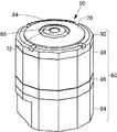
In FIG. 1, the external view of the
図1〜図4を参照して、香りディスプレイ50は、ほぼ正12角柱形状の平面形状を持つ筐体60を持つ。筐体60は、香りディスプレイ50の基部を形成し、上記した香り成分を含まない空気の噴射機構を内蔵したほぼ正12角形の平面形状を持つベース筐体84と、ベース筐体84の上部からベース筐体84に組付けられる、正12角形の平面形状を持つ中間筐体86と、中間筐体86の上部に組付けられ、内部に12個の香りカートリッジ130、132、…、134、135、…、136(図2、図3、図7及び図8参照)を収容するカートリッジ収容部110(図7及び図8を参照)を持つ、正12角形の平面形状の上部筐体88と、上部筐体88の上部開口を覆うように上部筐体88に着脱可能に組付けられる、これも正12角形の平面形状を持つトップパネル90とを含む。このトップパネル90の中央部には香りを含まない空気の流通路となる開口68が設けられている。トップパネル90は上部筐体88の上部に対して着脱可能である。トップパネル90を上部筐体88からはずすことで上部筐体88の上部が開放され、ユーザが香りカートリッジの収容部110にアクセス可能になり、香りカートリッジ130、…を収容部内に装填したり、収容部から取り外したりできる。 1 to 4, the
図4及び図5を参照して、トップパネル90は、上部筐体88の上面に着脱可能に取り付けられる、中央部に孔部を持つベース部材172と、この孔部を覆うようにベース部材172の上面に取り付けられるキャップ170とを含む。 4 and 5, the
ベース部材172は、中央に孔部を持つドーナツ状の外側部材70と、外側部材70の孔部内に設けられた内側部材72とを含む。外側部材70の底面側の開口184(図5)の内径は、上面側開口176(図4)の内径より大きくなっている。上面側開口176と底面側開口184とを結ぶ孔部の壁面は、底面側開口184と上面側開口176とをなめらかに結ぶ曲面を形成している。この曲面は、孔部の内径が外側部材70の底部から上面に向かって直線的に小さくなるように、すなわち単調に減少するように傾斜している。 The
内側部材72の側面174には12個の下部仕切り178が突き出るように形成され、この仕切板178により内側部材72が外側部材70の孔部の内側面に固定されている。内側部材72はその中央に、後述するシロッコファンにより形成される空気の流通路となる、上下に貫通する開口68を持つ。内側部材72の下面は円形であり、その外径は外側部材70の底面側の開口184の内径よりも小さい。内側部材72の上面も円形であり、その外径は外側部材70の上面側開口176の内径よりも小さい。内側部材72の側面は、上面の外縁及び下面の外縁をなめらかに結ぶ曲面であり、その曲面と外側部材70の内側曲面との間の距離が一定となるように形成されている。 Twelve
一方、キャップ170は、開口176よりやや大きな直径で、中央に開口領域64を持ち、上に凸に緩やかな曲面を描くキャップ本体190と、キャップ本体190の下面に、外側部材70の仕切板178と噛み合うように形成され、キャップ本体190を外側部材70に固定するための12個の爪部180とを含む。キャップ本体190の下面には円形の壁部が形成されており、爪部180はこの壁部の下端に、仕切板178の幅とほぼ等しい間隔を開けて形成されている。また、壁部の内側面の、隣接する爪部180の間の部分には、上側仕切板182が形成されている。 On the other hand, the
図6を参照して、キャップ170をベース部材172に組み付けると、ベース部材172の外側部材70及び内側部材72、及びキャップ170が上記した形状を持つため、外側部材70と内側部材72との間には、空気の通路が形成される。このとき、ベース部材172の各仕切板178(図5)と上側仕切板182とがその端部で接し、1つの仕切板を形成する。その結果、ベース部材172の孔部の外側部材70と内側部材72との間の空間は、これら仕切板により12個の空間からなる空気の通路186に分割される。上部筐体88に収容される12個の香りカートリッジ130、…からの香気は、それぞれこの空気の通路186のうち、その香りカートリッジ130、…の位置のものを通ってトップパネル90の外側に噴射される。 Referring to FIG. 6, when the
この実施の形態では、上部筐体88の断面は正12角形状をしており、上部筐体88の内部には複数個の香りカートリッジを収容可能なカートリッジ収容部が形成されている。特に、図2及び図3に示すとおり、上部筐体88の内部には、12個の香りカートリッジ130、…が装填されている。 In this embodiment, the
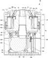
図3を参照して、ベース筐体84の下面には、後述するように空気の取り入れ口となる複数の開口部100が設けられる。図10を参照して、ベース筐体84の底部には、底板94が設けられる。底板94には空気の流通経路となる複数の開口部96が形成されている。底板94の上面には、無線通信により外部と通信可能な通信装置と、香りディスプレイ50内の風力源を駆動する制御回路とを搭載した制御基板98、その電源となる図示しないバッテリーが搭載されている。底板94の上面にはさらに、制御基板98上の制御回路により制御されて動作する、香りを含まない空気からなる空気流を生成し、トップパネル90に設けた開口68に向けて吐出口121から送り出すためのシロッコファン120及びその駆動回路基板126が、取付板128並びに取付部材122及び124をそれぞれ介して取付けられている。 Referring to FIG. 3, a plurality of
シロッコファン120の吐出口121には、吐出口121を覆うように形成された吸入口を持つノズル92が設けられている。ノズル92の先端112はその基部より小径の、丸みを帯びた正方形状となっている。 A
香りディスプレイ50はさらに、上部筐体88の底部と中間筐体86の上部との間に位置するように、金属板106により駆動回路基板126に固定され、制御基板98と香りカートリッジ130、…のための風力源との間を中継する中継基板102を含む。中継基板102の中央には、ノズル92の上部が挿入される開口104が形成されている。 Further, the
特に図3及び図10を参照して、上部筐体88の内部には、シロッコファン120からの空気の通路を持ち、上部筐体88のほぼ内部全面を覆うように形成されたフランジと空気の通路を規定する筒部とからなり、上部筐体88の内部を空気の流通路140の内部と香りカートリッジ130、132、…、134、135、…、136等を収容するカートリッジ収容部110とに区画し、シロッコファン120からの空気を空気の流通路140内にガイドするガイド部材114が設けられる。ガイド部材114の先端は上部筐体88の上面から少し上に突き出している。ガイド部材114により規定される空気の流通路140は円形断面を持ち、ガイド部材114の中で、空気の流通路140の下部を形成する円筒部116にはノズル92の先端112が挿入される形で嵌め合わされている。すなわち、ノズル92は、シロッコファン120の吐出口121と空気の流通路140とをカプリングし、シロッコファン120の吐出する空気を空気の流通路140に導くための部材となっている。 In particular, referring to FIGS. 3 and 10, the
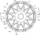
図7及び図8は、それぞれ、上部筐体88の上端からトップパネル90を取り除いたときのカートリッジ収容部110の斜視図及び平面図である。図7及び図8を参照して、上部筐体88の内部はガイド部材114により空気の流通路140と香りカートリッジ130、132、…、134、135、…、136等を収容するカートリッジ収容部110とに区画されている。 7 and 8 are a perspective view and a plan view of the
上部筐体88の内部のカートリッジ収容部110のガイド部材114の上面には、香りカートリッジを収容する収容部を規定するように香りカートリッジ130、…を保持する仕切200、仕切202等が形成されている。この各正三角形の底辺は上部筐体88の正12角形の各辺と平行になっている。上部筐体88の正12角形の各辺の中央部の内面には、12個のマイクロブロア138、…が設けられている。マイクロブロア138等の位置は、香りカートリッジ130、…に形成される、空気を香りカートリッジに導入するための給気口の位置と一致するように選ばれている。仕切200のうち周縁側は接続部206により上部筐体88と一体となっており、中心側はリブ208を介して上部筐体88の中心の円筒部分に接続されている。 On the upper surface of the
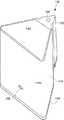
図9を参照して、例えば香りカートリッジ130は、断面がほぼ正三角形の中空の三角柱状で、互いに平行な上面142及び下面144、並びにこれらの周囲をつなぐように形成された側面146とからなる筐体150を持つ。筐体150の内部の空間には、香気を発生する香源が保持されている。香りカートリッジ130の上面142の中で、筐体150の縦方向の1つのエッジ152の近傍には、筐体150の内部の空間と外部とを連絡する、香気の通路の噴出口160が形成されている。側面146の中で、エッジ152と反対側の面の下部には、マイクロブロア138からの空気を筐体150内部の空間に送り込むための給気口158が形成されている。給気口158から筐体150の内部空間に空気を送り込むと、筐体150の内部空間の香気が噴出口160から外部に放出される。Referring to FIG. 9, for example, the
図10を参照して、ガイド部材114の底部のフランジ部分の上面には、香りカートリッジ130、…を位置決めするための仕切200、202等が形成されている。ガイド部材114の筒状部材とマイクロブロア138との間に、噴出口160が形成されたエッジ152が上部筐体88の中央を向くように香りカートリッジ130、…を挿入する。これにより、図8に示すように、香りカートリッジ130、…が上部筐体88の内面に沿って規則出しく等間隔で配置される。香りカートリッジ130、…の外側面及び内側の角部とは、いずれも上部筐体88の中心を中心とする、それぞれ所定の半径の同心の円上に整列される。この実施の形態では、各香りカートリッジ130、…の外側面が配置される円(これを「外側円」という。)の半径は、エッジ152が配置される円(これを「内側円」という。)の半径の2倍以上となっている。香りカートリッジ130、…の断面形状が正三角形状であり、かつ上記2つの円の間の関係が上に説明したとおりとなっているため、隣接するどの2つの香りカートリッジの間でも、中心側の角部の間にはある程度の空間が形成される。この空間内に指を入れて香りカートリッジをはさみ、引き抜くことで香りカートリッジ130、…を容易に交換できる。外側円の半径は、内側円の1.5倍程度以上であれば、香りカートリッジの交換には問題ないが、あまりその差が大きくなると上部筐体88の内部に余分な空間が生じる。そこで、外側円の半径は、内側円の4倍程度までに収めることが望ましい。 10,
この例では、香りカートリッジ130、…が上部筐体88の中心軸を中心として回転対称(12回転対称)の位置に配置される。このような配置とすることで、香りカートリッジを効率的に収容しながら、どの香りカートリッジからの香気についても、同じ制御で同じ濃度の香気を噴出できるという効果がある。 In this example, the
各香りカートリッジ130、…がカートリッジ収容部110に装着されると、香りカートリッジ内部に空気を送り込むための給気口158が上部筐体88の外側を向くことになる。例えば図10を参照して、香りカートリッジ130の場合、給気口158が外側を向く。上部筐体88の内面と香りカートリッジ130との間には、給気口158に空気を送り込むマイクロブロア138が配置されている。このマイクロブロア138を駆動することで香りカートリッジ132の内部に空気が送り込まれ、中心側に位置する香りカートリッジ132の香り噴出のための噴出口160(図9を参照)から香りを含んだ空気が外部に噴出される。なお、香りカートリッジ132等からの香気の噴出を効率的にするため、噴出口160はトップパネル90に形成されている空気の通路186に対向するように形成されている。トップパネル90と上部筐体88とは、この噴出口160及び空気の通路186の周囲では空気の通路186以外に香気が逃げないよう、気密になるように組み付けられる。 When each
マイクロブロア138は、上記特許文献1に開示されたものと同様の構成を持つ。図12を参照して、具体的には、マイクロブロア138は、内部空間であるブロア室252を持つケース250と、ブロア室252を塞ぐようにケース250の上面を覆って取り付けられ、上面に形成されたノズル270を持つカバー部材254とを含む。ノズル270内部には空気の流通孔256が形成されており、流通孔256はブロア室252の上部に開口している。 The
ブロア室252内部にはブロア室252を上下2つの部分に仕切る仕切板258が設けられている。仕切板258の、流通孔256の開口直下には、流通孔256と位置合わせされた開口260が形成されている。 A
仕切板258により仕切られたブロア室252の下部空間には、バネ弾性を持つ金属薄板で形成されたダイアフラム262と、ダイアフラム262の下面に接着された圧電素子264とを含む。圧電素子264に交番電圧を印加することでダイアフラム262が上下に振動して開口260を通して空気をブロア室252内に吐出し、さらに流通孔256を通じて外部に吹き出す。ノズル270が香りカートリッジ背面の給気口158の位置に来るようにマイクロブロア138を上部筐体88の内部に設け、交番電圧を所定の間印加することで、香りカートリッジ内に任意のタイミングで任意の時間の間空気を送り込むことができる。その結果、香りカートリッジから香りを含んだ空気を任意の時間にわたり噴出させることができる。なお、ケース250には空気の取入れ口266が設けられており、取入れ口266の空気が流通路268を介してブロア室252内に供給される。取入れ口266には、後述するように筐体60の底面からの空気が供給される。A lower space of the
香りカートリッジ130以外についても、背面側の開口から内部に空気を送り込むマイクロブロアがそれぞれ配置されている。これらを独立に動作させることにより、任意の香りカートリッジから任意のタイミングで、任意の時間だけ香気を外部に噴出できる。 In addition to the
図11は、図8において矢印11−11で示す方向の矢視断面図である。この図では、香りカートリッジの断面は現れておらず、香りカートリッジの位置決めをする仕切200及び204が図示されている。図11を参照して、香りカートリッジ130の位置決めをする仕切200は、香りカートリッジ130の側面のうち、下部の7割程度までの高さを持ち、香りカートリッジ130を保持している。仕切200のうち周縁側は接続部206により上部筐体88と一体となっており、中心側はリブ208を介して上部筐体88に接続されている。香りカートリッジ135についても同様である。 FIG. 11 is a cross-sectional view taken in the direction of the arrow 11-11 in FIG. In this figure, the cross section of the scent cartridge does not appear, and
図8、図10及び図11により示されるように、香りカートリッジ130、…の3つのエッジのうち、噴出口160が形成されている部分に近いエッジとガイド部材114との間には一定の距離がある。この距離は、1センチメートル以上であることが望ましい。また、図7及び図11に示されるように、仕切200及び202は、香りカートリッジ130、…の側面のうち、噴出口160が形成されている部分に近いエッジを挟む側面の上部の少なくとも一部を露出するように形成されている。このような構成をとると、香りカートリッジ130、…のうち、隣接する2つの香りカートリッジの頂点間には一定の間隔が形成される。さらに、各香りカートリッジとガイド部材114の外側表面との間には少なくとも1センチメートルの間隔が確保されている。したがってこの部分に指を差し入れ、香りカートリッジをつまんで取り出すことが容易にできる。さらに、香りカートリッジ130、…の側面の一部が露出しているため、この部分を指で挟むことが容易に行える。その結果、香りカートリッジ130、…を容易に交換できるという効果が生じる。 As shown in FIGS. 8, 10, and 11, among the three edges of the
図2、図3及び図10に示すシロッコファン120は、マイクロブロア138と異なり、通常のブラシレスモータにより駆動される。ブラシレスモータは専用の駆動回路(駆動回路基板126上の回路)を必要とするが、安定した回転速度で動作でき、メンテナンスも不要という利点がある。さらに発生する騒音も小さいため、香りディスプレイが利用される場面を選ばない。このシロッコファン120を駆動することで、任意のタイミングで任意の間、多くの空気を図1、図2、図3及び図10等に示すトップパネル90の開口68から放出させることができる。シロッコファン120が送り出す空気の量は、マイクロブロア138によるものと比較してはるかに多い。 Unlike the
図13に、香りディスプレイ50内部における空気の流れを示す。図13において、香りカートリッジ130、…に供給される空気及び香りカートリッジ130、…から放出される香気の流れは細線の矢印で示す。シロッコファン120に供給される空気及びシロッコファン120から送り出される空気の流れは太線の矢印で示す。 FIG. 13 shows the flow of air inside the
香りカートリッジ130、…を代表して香りカートリッジ130への空気の流れを以下に説明する。ベース筐体84の底面及び底板94にはそれぞれ多数の開口部100及び96が形成されており、この開口部100及び96を通して空気が筐体60内に取り込まれる。この空気は、ベース筐体84内及び中間筐体86内に形成された空気の移動経路300及び302を通って、上部筐体88内のマイクロブロア138に供給される。マイクロブロア138内の圧電素子264(図12参照)に交番電圧が印加されることによりマイクロブロア138から送り込まれた空気は給気口158を通って香りカートリッジ130の内部に導かれる。 The flow of air to the
香りカートリッジ130の内部にマイクロブロア138によって空気が導き入れられると、香りカートリッジ130内の圧力が高くなる。その結果、香りカートリッジ130内の香気を含んだ空気が香りカートリッジ130の噴出口160から香りカートリッジ130に対応するトップパネル90の空気の通路186を経由しトップパネル90の開口領域64を通って外部に噴射される。他の香りカートリッジの場合も同様である。 When air is introduced into the
一方、シロッコファン120の場合、香りカートリッジ130、…と同様、ベース筐体84の底面及び底板94の開口部100及び96から空気が供給される。供給された空気は、シロッコファン120が駆動されると吐出口121からノズル92及び上部筐体88内部の空気の流通路140の内部を通ってトップパネル90に形成された開口68から外部に噴射される。シロッコファン120の空気の噴射量はマイクロブロアと比較してはるかに多いので、香りカートリッジ130、…から香りを含んだ空気を噴射した後にこの開口68から空気を噴射すると、周囲に残存していた香りを含んだ空気は消散し、香りが混ざることなく別の香りに切替えることができる。また香りカートリッジ130、…から香気を継続して噴出させるのと並行してシロッコファン120を駆動することで、シロッコファン120の生成する空気の流れにより香りを遠くまで搬送し、広い範囲に香りを行き渡らせることができる。 On the other hand, in the case of the
すなわち、シロッコファン120は、香りを含んだ空気を遠方に到達させるためのブースター機能も果たす。さらに、シロッコファン120による空気の噴射量及び速度を制御することによって、開口領域64から噴射される香りの濃度を制御できる。さらに開口68からの空気と開口領域64からの空気との噴射量の制御によって、香りディスプレイ50の調香機能を果たすこともできる。 That is, the
なお、この実施の形態では、空気の流通路140内部を流れる空気の流れで香りカートリッジ130等からの香気を搬送する。空気の流通路140の内部を流れる空気の流速が噴出口160からの空気の流速と比較してあまりに大きいと、香りの効果を十分に得ることができない可能性がある。それを防止するために、シロッコファン120から吐出される空気の速度自体を制御すればよいが、空気の流通路140の内径が途中で絞られていたりすると流速が大きくなる可能性がある。そこで、この実施の形態では、空気の流通路140の内径が噴出口160の内径の10倍以上で20倍以下となるようにした。こうすることで、シロッコファン120から吐出される空気の量をあまり小さくしなくても、開口68の部分の空気の流速が噴出口160からの香気の速度と大きく相違することはなくなる。その結果、香りを制御性高く噴射できるという効果がある。 In this embodiment, the fragrance from the
<動作>
上記した香りディスプレイ50は以下のように動作する。<Operation>
The
各香りカートリッジ130、…には、その内部の香源に応じたラベルが貼られている。香りディスプレイ50のユーザは、自分が気に入った香りの香りカートリッジを購入し以下の手順で香りディスプレイ50に装填する。 Each
図2及び図7を参照して、トップパネル90を上部筐体88から取り外すことにより、上部筐体88の上部開口が露出する。図10に示すように、ユーザは上部筐体88の内部のカートリッジ収容部110の任意の位置に香りカートリッジを装填する。例えば12個の全てのカートリッジ収容部に香りカートリッジを装填する。ユーザは、香りカートリッジの装填後、トップパネル90を筐体60に取り付ける。 With reference to FIGS. 2 and 7, the top opening of the
図示しないコンピュータを用いて、香気の噴射のタイミングと、香気を噴射する香りカートリッジの指定とを行い、さらにそのときのシロッコファン120の生成する空気流の大きさとを指定する。コンピュータは、指定されたタイミングで、指定された香りカートリッジから香りを噴出させるよう、香りディスプレイ50の制御基板98にコマンドを送信する。このコマンドを受信した制御基板98は、指定された香りが装填されたカートリッジ収容部110のマイクロブロア138に、指定されたタイミングで指定された長さだけ交番電圧を加える。その結果、香りディスプレイ50からは、コンピュータにより指定されたタイミングで、指定された香りが指定された時間だけ噴射される。さらに、制御基板98は、香りを噴射する間と、香りを噴射した後とで、それぞれ別々にシロッコファン120を制御し、シロッコファン120が生成する空気流の大きさを変化させる。 Using a computer (not shown), the timing of injecting the fragrance and the designation of the scent cartridge for injecting the fragrance are performed, and the size of the air flow generated by the
以上のようにこの実施の形態に係る香りディスプレイ50によれば、従来のマイクロブロアに変わり、香りを含まない空気流を生成するためにシロッコファンを用いている。シロッコファンはマイクロブロアと比較してはるかに多くの空気を送り出すころができる。その結果、遠くまで香りを届けるブースター効果を実現できる。また、香気を噴射した後に香気を含まない空気の流れをシロッコファン120により生成することで、香気をすばやく消散させられる。このときの空気の量は、マイクロブロアと比較してはるかに大きく、香気をすばやく、確実に消散させることができる。その結果、次に別の香気を噴射させる際に香りが混ざってしまうことが防止できる。 As described above, according to the
また上記実施の形態では、カートリッジ収容体110の内径を香りカートリッジ130、…の大きさと比較してより大きくした。カートリッジ収容体110に香りカートリッジ130、…を装填した際にも、任意の隣り合う2つの香りカートリッジの間には、比較的大きな空間が残っている。そのため、その間に指を入れて香りカートリッジ130、…をつかんで取り出す容易にできる。その結果、香りカートリッジ130、…の交換が従来と比較してはるかに容易になるという効果がある。香りカートリッジ収容部110を形成する仕切200及び202等の高さを、香りカートリッジ130、…の高さよりも低くしている。仕切200及び202等は、香りカートリッジの下方の一部のみを囲むだけで、上端部分については香りカートリッジを露出している。この部分を指で挟むことでユーザは容易に香りカートリッジ130、…を香りディスプレイ50から取出し、交換できる。そのための工具は不要で、特に大きな力を必要とすることもない。その結果、香りカートリッジ130、…の交換が容易になるという効果がある。 Moreover, in the said embodiment, the internal diameter of the
上記実施の形態では、12個の香りカートリッジ130、…をカートリッジ収容部110内に12回転対称な位置に配置している。しかしこの発明はそのような実施の形態には限定されない。香りカートリッジの個数は12個には限定されず、それより多くても、それより小さくてもよい。ただし、実用的な観点、及び香りディスプレイ50の全体サイズを考慮すると香りディスプレイ50に装着可能な香りカートリッジの数は6以上で24個以下とすることが望ましい。香りカートリッジの数が6個未満であれば、装置の大きさに比して使用できる香りカートリッジの数が少なすぎ、実用的でない。また香りカートリッジの数が24個より大ければ、筐体60のサイズが大きくなりすぎ、これも実用的ではない。また香りカートリッジを回転対称な位置に配置することは必須ではない。香りカートリッジを回転対称でない位置に配置してもよい。ただし、どの香りカートリッジについても同様の制御を行って同様の効果を得るためには、香りカートリッジを回転対称な位置に設けることが望ましい。また香りカートリッジを回転対称な位置に設けることにより、筐体60の製造がより容易になるという効果がある。 In the above embodiment, the twelve
さらに上記実施の形態では、香りを含まない空気流を生成するためにシロッコファンを用いている。シロッコファンは、速度制御が安定して行え、生成される空気流も大きいとい効果がある。さらにブラシレスモータを用いた場合には、騒音も小さく、香りディスプレイを使う場面を選ばないという効果もある。しかしこの発明はそのような実施の形態には限定されない。例えば大きな空気流を生成するという目的のためにはプロペラファン、クロスフローファン等を用いても良い。また、交流電源が使用できる場合には、交流モータを駆動源とするファンを採用してもよい。要するに、所望のタイミングで、所望の量の空気流を、所望の時間だけ生成できるような風力源であり、かつ筐体内に収まるようなものであれば、どのようなものを用いても良い。 Furthermore, in the said embodiment, in order to produce | generate the air flow which does not contain fragrance, the sirocco fan is used. The sirocco fan has an effect that the speed control can be stably performed and the generated air flow is large. Furthermore, when a brushless motor is used, the noise is small, and there is an effect that the scene where the scent display is used is not selected. However, the present invention is not limited to such an embodiment. For example, a propeller fan, a cross flow fan, or the like may be used for the purpose of generating a large air flow. When an AC power source can be used, a fan using an AC motor as a drive source may be employed. In short, any wind source that can generate a desired amount of airflow at a desired timing for a desired time and that can be accommodated in the housing may be used.
上記実施の形態では、香りカートリッジとして上面及び下面が正三角形の柱状のものを用いている。しかしこの発明はそのような実施の形態には限定されない。上面及び下面がそれ以外の形状であってもよい。また側面が平坦でなくてもよく、凹凸があってもよい。しかし側面が平坦な方が、香りカートリッジの着脱が容易になるのでより好ましい。上記実施の形態では、香りカートリッジを交換している。しかし、香りカートリッジを収納した上部筐体88をまるごと交換可能としてもよい。 In the said embodiment, the thing of a column shape whose upper surface and lower surface are equilateral triangles is used as a scent cartridge. However, the present invention is not limited to such an embodiment. The upper surface and the lower surface may have other shapes. Further, the side surface does not have to be flat and may have irregularities. However, it is more preferable that the side surface is flat because the scent cartridge can be easily attached and detached. In the above embodiment, the scent cartridge is exchanged. However, the entire
また、上記実施の形態では、単独の香りカートリッジから香りを噴射する場合を例にしたが、この発明はそうした実施の形態には限定されない。同時に複数種類の香りを噴射することで、香りディスプレイに装填された香りカートリッジの香りとは全く別の香りを合成することもできる。 Moreover, in the said embodiment, although the case where a scent was injected from a single scent cartridge was taken as an example, this invention is not limited to such an embodiment. By ejecting a plurality of types of scents at the same time, a scent completely different from the scent of the scent cartridge loaded in the scent display can be synthesized.
今回開示された実施の形態は単に例示であって、本発明が上記した実施の形態のみに制限されるわけではない。本発明の範囲は、発明の詳細な説明の記載を参酌した上で、特許請求の範囲の各請求項によって示され、そこに記載された文言と均等の意味及び範囲内での全ての変更を含む。 The embodiment disclosed herein is merely an example, and the present invention is not limited to the above-described embodiment. The scope of the present invention is indicated by each claim of the claims after taking into account the description of the detailed description of the invention, and all modifications within the meaning and scope equivalent to the wording described therein are included. Including.
50 香りディスプレイ
60、150 筐体
64 開口領域
68、104、176、184、260 開口
70 外側部材
72 内側部材
84 ベース筐体
86 中間筐体
88 上部筐体
90 トップパネル
92、270 ノズル
94 底板
96、100 開口部
98 制御基板
102 中継基板
106 金属板
110 カートリッジ収容部
112 先端
114 ガイド部材
116 円筒部
120 シロッコファン
121 吐出口
122 取付部材
126 駆動回路基板
128 取付板
130、132、134、136 香りカートリッジ
138 マイクロブロア
140、268 空気の流通路
142 上面
144 下面
146、174 側面
152 エッジ
158 給気口
160 噴射口
170 キャップ
172 ベース部材
178 仕切板278
180 爪部
182 上側仕切板
186 空気の通路
190 キャップ本体
200、202 仕切
206 接続部
208 リブ
250 ケース
252 ブロア室
254 カバー部材
256 流通孔
258 仕切り板
262 ダイアフラム
264 圧電素子
266 取入れ口
300、302 空気の移動経路
50
180
Claims (6)
Translated fromJapanese前記香りカートリッジは、互いに対向する第1の面及び第2の面と、前記第1の面の第1の端点と前記第2の面の第1の端点とを接続する、少なくとも1つのエッジを持つ第3の面とを持つ中空の柱状体であり、かつ、前記第1の面の前記第1の端点の近傍には、前記柱状体の内部の空間と通じ、前記内部の空間からの香気を含む空気を噴出する噴出口が形成されており、
前記カートリッジ収容筐体は、第1の端部及び第2の端部を持ち、
前記香りディスプレイは、
前記カートリッジ収容筐体の前記第2の端部側に設けられ、駆動信号に応答して動作するファンと、
前記カートリッジ収容筐体の前記第1の端部側に前記カートリッジ収容筐体を覆うように取り付けられ、かつ中央に開口部を有するトップパネルと、を含み、
前記カートリッジ収容筐体の内部には、前記ファンからの空気流を前記トップパネルの前記開口部に導くように筒状のガイド部材が設けられ、当該ガイド部材により、前記カートリッジ収容筐体は、前記ガイド部材内部と、前記ガイド部材外部であって前記複数個の香りカートリッジが収容されるカートリッジ収容部とに分割され、
前記トップパネルは、前記開口部を内側開口部と外側開口部とに分離する第1の部材と、前記開口部の外周を規定する第2の部材とを含み、前記内側開口部は前記ガイド部材内部に通じ、
前記カートリッジ収容部は、前記ガイド部材を中心として、前記第1の面が前記トップパネル側を向くように、かつ前記噴出口が前記ガイド部材側に位置するように前記複数個の香りカートリッジを収容し、
前記カートリッジ収容部に収容された前記複数個の香りカートリッジは、いずれも、その前記噴出口が前記外側開口部に対向する位置に配置され、
前記香りディスプレイはさらに、前記カートリッジ収容部内に、前記複数個の香りカートリッジに対応して設けられ、それぞれの駆動信号により制御されて、それぞれの香りカートリッジ内の香気を含む空気を前記香りディスプレイ外に噴出させる噴出駆動部を含む、香りディスプレイ。A scent display, each containing a scent source, containing a plurality of scent cartridges having a certain three-dimensional shape, and ejecting scent from each scent cartridge to the outside of the casing ,
The scent cartridge has at least one edge connecting a first surface and a second surface facing each other, a first end point of the first surface, and a first end point of the second surface. A hollow columnar body having a third surface, and in the vicinity of the first end point of the first surface, communicates with a space inside the columnar body, and aroma from the space inside the columnar body. A spout for ejecting air containing is formed,
The cartridge housing case has a first end and a second end,
The scent display
A fan provided on the second end side of the cartridge housing case and operating in response to a drive signal;
A top panel attached to the first end side of the cartridge housing case so as to cover the cartridge housing case and having an opening in the center,
Inside the cartridge housing case, a cylindrical guide member is provided so as to guide the air flow from the fan to the opening of the top panel. It is divided into a guide member inside and a cartridge housing part in which the plurality of scent cartridges are housed outside the guide member,
The top panel includes a first member that separates the opening into an inner opening and an outer opening, and a second member that defines an outer periphery of the opening, and the inner opening is the guide member. Inside,
The cartridge housing portion houses the plurality of scent cartridges with the guide member as a center so that the first surface faces the top panel and the ejection port is located on the guide member side. And
Each of the plurality of scent cartridges housed in the cartridge housing part is disposed at a position where the jet port faces the outer opening,
The scent display is further provided in the cartridge housing portion corresponding to the plurality of scent cartridges, and is controlled by respective drive signals so that the air containing the scent in each scent cartridge is removed from the scent display. A scent display that includes an ejection drive unit for ejection.
前記香りカートリッジの平面視は略三角形であり、
前記エッジは前記第1の面及び第2の面の前記三角形の第1の頂点を結ぶエッジであり、
前記香りカートリッジは、前記第1の頂点から前記ガイド部材の外側面との間の距離が少なくとも1センチメートル以上離れるように前記保持部材により保持される、請求項1又は請求項2に記載の香りディスプレイ。The cartridge housing case has a holding member for positioning and holding the plurality of scent cartridges at predetermined positions,
The plan view of the scent cartridge is substantially triangular,
The edge is an edge connecting a first vertex of the triangle of the first surface and the second surface;
The scent according to claim 1 or 2, wherein the scent cartridge is held by the holding member such that a distance between the first apex and an outer surface of the guide member is at least 1 centimeter or more. display.
前記香りカートリッジは、互いに対向する、いずれも三角形の第1及び第2の面と、前記第1及び第2の面を接続する側面とを持ち、前記第1の面の第1の頂点の近傍には、前記三角柱状体の内部の空間と通じ、前記内部の空間からの香気を含む空気を噴出する噴出口が形成されており、
前記カートリッジ収容筐体は、第1の端部及び第2の端部を持ち、
前記香りディスプレイはさらに、前記カートリッジ収容筐体の前記第1の端部側に前記カートリッジ収容筐体を覆うように着脱可能に組み付けられ、かつ中央に開口部を有するトップパネルを含み、
前記カートリッジ収容筐体の内部には、所定の風力発生源からの空気流を前記トップパネルの前記開口部に導くように筒状のガイド部材が設けられ、当該ガイド部材により、前記カートリッジ収容筐体の内部は、前記ガイド部材内部と、前記ガイド部材外部であって前記複数個の香りカートリッジが収容されるカートリッジ収容部とに分割され、
前記カートリッジ収容部は、前記ガイド部材を中心として、前記第1の面が前記トップパネル側を向くように、かつ前記噴出口が前記ガイド部材側に位置するように前記複数個の香りカートリッジを収容し、
前記カートリッジ収容筐体は、前記カートリッジ収容部内に形成された、前記複数個の香りカートリッジを保持する保持部材を持ち、当該保持部材は、前記複数個の香りカートリッジを、各々の前記第1の面の前記第1の頂点と、前記ガイド部材の外側面との間の距離が少なくとも1センチメートル以上離れるように位置決めして保持する、香りディスプレイ。A scent display, each containing a scent source, containing a plurality of scent cartridges having a triangular prism shape and ejecting scent from each scent cartridge to the outside of the cartridge housing case ,
The scent cartridge has first and second triangular faces and side faces that connect the first and second faces, both facing each other, and in the vicinity of the first vertex of the first face. Is formed with a spout that communicates with the space inside the triangular prism and ejects air containing aroma from the space inside,
The cartridge housing case has a first end and a second end,
The scent display further includes a top panel that is detachably assembled on the first end side of the cartridge housing case so as to cover the cartridge housing case, and has an opening in the center.
A cylindrical guide member is provided inside the cartridge housing case so as to guide an air flow from a predetermined wind power generation source to the opening of the top panel. The inside of the guide member is divided into the inside of the guide member, and the cartridge housing portion outside the guide member and housing the plurality of scent cartridges,
The cartridge housing portion houses the plurality of scent cartridges so that the first surface faces the top panel with the guide member as a center, and the ejection port is located on the guide member side. And
Said cartridge containment enclosure,formed in said cartridge housing portionhas a holding member for holding the plurality of scent cartridges, the holding member,the plurality of scentcartridges, each said first surface of wherein a first apex, the distance between the outer surface of the guide member is held by tanningposition-decided away at least 1 cm ormore, the scent display.
Priority Applications (1)
| Application Number | Priority Date | Filing Date | Title |
|---|---|---|---|
| JP2019029388AJP6619896B1 (en) | 2019-02-21 | 2019-02-21 | Scent display |
Applications Claiming Priority (1)
| Application Number | Priority Date | Filing Date | Title |
|---|---|---|---|
| JP2019029388AJP6619896B1 (en) | 2019-02-21 | 2019-02-21 | Scent display |
Publications (2)
| Publication Number | Publication Date |
|---|---|
| JP6619896B1true JP6619896B1 (en) | 2019-12-11 |
| JP2020130714A JP2020130714A (en) | 2020-08-31 |
Family
ID=68836057
Family Applications (1)
| Application Number | Title | Priority Date | Filing Date |
|---|---|---|---|
| JP2019029388AActiveJP6619896B1 (en) | 2019-02-21 | 2019-02-21 | Scent display |
Country Status (1)
| Country | Link |
|---|---|
| JP (1) | JP6619896B1 (en) |
Family Cites Families (1)
| Publication number | Priority date | Publication date | Assignee | Title |
|---|---|---|---|---|
| JP5288573B1 (en)* | 2012-11-02 | 2013-09-11 | 独立行政法人情報通信研究機構 | Olfactory display and incense source cartridge used therefor |
- 2019
- 2019-02-21JPJP2019029388Apatent/JP6619896B1/enactiveActive
Also Published As
| Publication number | Publication date |
|---|---|
| JP2020130714A (en) | 2020-08-31 |
Similar Documents
| Publication | Publication Date | Title |
|---|---|---|
| KR101634511B1 (en) | Olfactory display and fragrance source cartridge used therein | |
| RU2609211C2 (en) | Humidifying apparatus | |
| RU2612561C2 (en) | Moisturizing installation | |
| KR101699293B1 (en) | A fan assembly | |
| JP6750079B1 (en) | Fragrance cartridge and method of attaching/detaching fragrance cartridge to/from fragrance display | |
| KR102272144B1 (en) | Booster device for fragrance display | |
| CN107036220B (en) | humidifier | |
| RU2648186C2 (en) | Humidifying apparatus | |
| CN103306944B (en) | Damping device | |
| KR20200054870A (en) | Fragrance cartridge and fragrance display | |
| KR102328763B1 (en) | Fragrance display | |
| JP6619896B1 (en) | Scent display | |
| JP5991685B1 (en) | Sprayer and spraying apparatus using the sprayer | |
| JP6179890B2 (en) | Olfactory display and incense source cartridge used therefor | |
| JP6735404B1 (en) | Scent display | |
| JP2007283281A (en) | Ultrasonic atomizing apparatus | |
| CN114222593A (en) | Liquid spraying device | |
| CN114304740A (en) | A sound insulation ventilation device and an electronic atomization device | |
| CN219423485U (en) | Main unit and electronic atomization device | |
| JP2019195442A (en) | Olfactory sense display | |
| JP7344615B1 (en) | chemical sprayer | |
| JP2019118889A (en) | Sprayer | |
| WO2024014222A1 (en) | Booster device for scent display | |
| JP2008161745A (en) | Droplet discharge device and air conditioner using the same | |
| JP2004194892A (en) | Bubble body generating and diffusing device |
Legal Events
| Date | Code | Title | Description |
|---|---|---|---|
| A621 | Written request for application examination | Free format text:JAPANESE INTERMEDIATE CODE: A621 Effective date:20190318 | |
| A871 | Explanation of circumstances concerning accelerated examination | Free format text:JAPANESE INTERMEDIATE CODE: A871 Effective date:20190425 | |
| A975 | Report on accelerated examination | Free format text:JAPANESE INTERMEDIATE CODE: A971005 Effective date:20190605 | |
| A131 | Notification of reasons for refusal | Free format text:JAPANESE INTERMEDIATE CODE: A131 Effective date:20190625 | |
| A521 | Request for written amendment filed | Free format text:JAPANESE INTERMEDIATE CODE: A523 Effective date:20190805 | |
| TRDD | Decision of grant or rejection written | ||
| A01 | Written decision to grant a patent or to grant a registration (utility model) | Free format text:JAPANESE INTERMEDIATE CODE: A01 Effective date:20191029 | |
| A61 | First payment of annual fees (during grant procedure) | Free format text:JAPANESE INTERMEDIATE CODE: A61 Effective date:20191115 | |
| R150 | Certificate of patent or registration of utility model | Ref document number:6619896 Country of ref document:JP Free format text:JAPANESE INTERMEDIATE CODE: R150 | |
| S531 | Written request for registration of change of domicile | Free format text:JAPANESE INTERMEDIATE CODE: R313531 | |
| R350 | Written notification of registration of transfer | Free format text:JAPANESE INTERMEDIATE CODE: R350 | |
| R250 | Receipt of annual fees | Free format text:JAPANESE INTERMEDIATE CODE: R250 |