JP6619456B2 - Medical manipulator system and method for operating medical manipulator system - Google Patents
Medical manipulator system and method for operating medical manipulator systemDownload PDFInfo
- Publication number
- JP6619456B2 JP6619456B2JP2017561464AJP2017561464AJP6619456B2JP 6619456 B2JP6619456 B2JP 6619456B2JP 2017561464 AJP2017561464 AJP 2017561464AJP 2017561464 AJP2017561464 AJP 2017561464AJP 6619456 B2JP6619456 B2JP 6619456B2
- Authority
- JP
- Japan
- Prior art keywords
- image
- manipulator
- external force
- pseudo
- endoscope
- Prior art date
- Legal status (The legal status is an assumption and is not a legal conclusion. Google has not performed a legal analysis and makes no representation as to the accuracy of the status listed.)
- Active
Links
Images


Classifications
- A—HUMAN NECESSITIES
- A61—MEDICAL OR VETERINARY SCIENCE; HYGIENE
- A61B—DIAGNOSIS; SURGERY; IDENTIFICATION
- A61B34/00—Computer-aided surgery; Manipulators or robots specially adapted for use in surgery
- A61B34/25—User interfaces for surgical systems
- A—HUMAN NECESSITIES
- A61—MEDICAL OR VETERINARY SCIENCE; HYGIENE
- A61B—DIAGNOSIS; SURGERY; IDENTIFICATION
- A61B1/00—Instruments for performing medical examinations of the interior of cavities or tubes of the body by visual or photographical inspection, e.g. endoscopes; Illuminating arrangements therefor
- A61B1/00002—Operational features of endoscopes
- A61B1/00004—Operational features of endoscopes characterised by electronic signal processing
- A61B1/00009—Operational features of endoscopes characterised by electronic signal processing of image signals during a use of endoscope
- A—HUMAN NECESSITIES
- A61—MEDICAL OR VETERINARY SCIENCE; HYGIENE
- A61B—DIAGNOSIS; SURGERY; IDENTIFICATION
- A61B1/00—Instruments for performing medical examinations of the interior of cavities or tubes of the body by visual or photographical inspection, e.g. endoscopes; Illuminating arrangements therefor
- A61B1/00131—Accessories for endoscopes
- A61B1/00133—Drive units for endoscopic tools inserted through or with the endoscope
- A—HUMAN NECESSITIES
- A61—MEDICAL OR VETERINARY SCIENCE; HYGIENE
- A61B—DIAGNOSIS; SURGERY; IDENTIFICATION
- A61B1/00—Instruments for performing medical examinations of the interior of cavities or tubes of the body by visual or photographical inspection, e.g. endoscopes; Illuminating arrangements therefor
- A61B1/00131—Accessories for endoscopes
- A61B1/00135—Oversleeves mounted on the endoscope prior to insertion
- A—HUMAN NECESSITIES
- A61—MEDICAL OR VETERINARY SCIENCE; HYGIENE
- A61B—DIAGNOSIS; SURGERY; IDENTIFICATION
- A61B1/00—Instruments for performing medical examinations of the interior of cavities or tubes of the body by visual or photographical inspection, e.g. endoscopes; Illuminating arrangements therefor
- A61B1/00147—Holding or positioning arrangements
- A61B1/00149—Holding or positioning arrangements using articulated arms
- A—HUMAN NECESSITIES
- A61—MEDICAL OR VETERINARY SCIENCE; HYGIENE
- A61B—DIAGNOSIS; SURGERY; IDENTIFICATION
- A61B1/00—Instruments for performing medical examinations of the interior of cavities or tubes of the body by visual or photographical inspection, e.g. endoscopes; Illuminating arrangements therefor
- A61B1/00147—Holding or positioning arrangements
- A61B1/00154—Holding or positioning arrangements using guiding arrangements for insertion
- A—HUMAN NECESSITIES
- A61—MEDICAL OR VETERINARY SCIENCE; HYGIENE
- A61B—DIAGNOSIS; SURGERY; IDENTIFICATION
- A61B1/00—Instruments for performing medical examinations of the interior of cavities or tubes of the body by visual or photographical inspection, e.g. endoscopes; Illuminating arrangements therefor
- A61B1/00147—Holding or positioning arrangements
- A61B1/0016—Holding or positioning arrangements using motor drive units
- A—HUMAN NECESSITIES
- A61—MEDICAL OR VETERINARY SCIENCE; HYGIENE
- A61B—DIAGNOSIS; SURGERY; IDENTIFICATION
- A61B34/00—Computer-aided surgery; Manipulators or robots specially adapted for use in surgery
- A61B34/70—Manipulators specially adapted for use in surgery
- A61B34/71—Manipulators operated by drive cable mechanisms
- A—HUMAN NECESSITIES
- A61—MEDICAL OR VETERINARY SCIENCE; HYGIENE
- A61B—DIAGNOSIS; SURGERY; IDENTIFICATION
- A61B90/00—Instruments, implements or accessories specially adapted for surgery or diagnosis and not covered by any of the groups A61B1/00 - A61B50/00, e.g. for luxation treatment or for protecting wound edges
- A61B90/06—Measuring instruments not otherwise provided for
- G—PHYSICS
- G06—COMPUTING OR CALCULATING; COUNTING
- G06T—IMAGE DATA PROCESSING OR GENERATION, IN GENERAL
- G06T11/00—2D [Two Dimensional] image generation
- H—ELECTRICITY
- H04—ELECTRIC COMMUNICATION TECHNIQUE
- H04N—PICTORIAL COMMUNICATION, e.g. TELEVISION
- H04N5/00—Details of television systems
- H04N5/44—Receiver circuitry for the reception of television signals according to analogue transmission standards
- H04N5/445—Receiver circuitry for the reception of television signals according to analogue transmission standards for displaying additional information
- H04N5/44504—Circuit details of the additional information generator, e.g. details of the character or graphics signal generator, overlay mixing circuits
- A—HUMAN NECESSITIES
- A61—MEDICAL OR VETERINARY SCIENCE; HYGIENE
- A61B—DIAGNOSIS; SURGERY; IDENTIFICATION
- A61B34/00—Computer-aided surgery; Manipulators or robots specially adapted for use in surgery
- A61B34/25—User interfaces for surgical systems
- A61B2034/256—User interfaces for surgical systems having a database of accessory information, e.g. including context sensitive help or scientific articles
- A—HUMAN NECESSITIES
- A61—MEDICAL OR VETERINARY SCIENCE; HYGIENE
- A61B—DIAGNOSIS; SURGERY; IDENTIFICATION
- A61B34/00—Computer-aided surgery; Manipulators or robots specially adapted for use in surgery
- A61B34/30—Surgical robots
- A61B2034/301—Surgical robots for introducing or steering flexible instruments inserted into the body, e.g. catheters or endoscopes
- A—HUMAN NECESSITIES
- A61—MEDICAL OR VETERINARY SCIENCE; HYGIENE
- A61B—DIAGNOSIS; SURGERY; IDENTIFICATION
- A61B90/00—Instruments, implements or accessories specially adapted for surgery or diagnosis and not covered by any of the groups A61B1/00 - A61B50/00, e.g. for luxation treatment or for protecting wound edges
- A61B90/06—Measuring instruments not otherwise provided for
- A61B2090/064—Measuring instruments not otherwise provided for for measuring force, pressure or mechanical tension
- A61B2090/065—Measuring instruments not otherwise provided for for measuring force, pressure or mechanical tension for measuring contact or contact pressure
- A—HUMAN NECESSITIES
- A61—MEDICAL OR VETERINARY SCIENCE; HYGIENE
- A61B—DIAGNOSIS; SURGERY; IDENTIFICATION
- A61B90/00—Instruments, implements or accessories specially adapted for surgery or diagnosis and not covered by any of the groups A61B1/00 - A61B50/00, e.g. for luxation treatment or for protecting wound edges
- A61B90/06—Measuring instruments not otherwise provided for
- A61B2090/067—Measuring instruments not otherwise provided for for measuring angles
- A—HUMAN NECESSITIES
- A61—MEDICAL OR VETERINARY SCIENCE; HYGIENE
- A61B—DIAGNOSIS; SURGERY; IDENTIFICATION
- A61B90/00—Instruments, implements or accessories specially adapted for surgery or diagnosis and not covered by any of the groups A61B1/00 - A61B50/00, e.g. for luxation treatment or for protecting wound edges
- A61B90/36—Image-producing devices or illumination devices not otherwise provided for
- A61B2090/364—Correlation of different images or relation of image positions in respect to the body
- A61B2090/365—Correlation of different images or relation of image positions in respect to the body augmented reality, i.e. correlating a live optical image with another image
- G—PHYSICS
- G06—COMPUTING OR CALCULATING; COUNTING
- G06T—IMAGE DATA PROCESSING OR GENERATION, IN GENERAL
- G06T11/00—2D [Two Dimensional] image generation
- G06T11/001—Texturing; Colouring; Generation of texture or colour
- G—PHYSICS
- G06—COMPUTING OR CALCULATING; COUNTING
- G06T—IMAGE DATA PROCESSING OR GENERATION, IN GENERAL
- G06T2210/00—Indexing scheme for image generation or computer graphics
- G06T2210/62—Semi-transparency
- G—PHYSICS
- G06—COMPUTING OR CALCULATING; COUNTING
- G06T—IMAGE DATA PROCESSING OR GENERATION, IN GENERAL
- G06T7/00—Image analysis
- G06T7/70—Determining position or orientation of objects or cameras
Landscapes
- Health & Medical Sciences (AREA)
- Life Sciences & Earth Sciences (AREA)
- Surgery (AREA)
- Engineering & Computer Science (AREA)
- Nuclear Medicine, Radiotherapy & Molecular Imaging (AREA)
- Public Health (AREA)
- Animal Behavior & Ethology (AREA)
- General Health & Medical Sciences (AREA)
- Veterinary Medicine (AREA)
- Biomedical Technology (AREA)
- Heart & Thoracic Surgery (AREA)
- Medical Informatics (AREA)
- Molecular Biology (AREA)
- Physics & Mathematics (AREA)
- Pathology (AREA)
- Optics & Photonics (AREA)
- Radiology & Medical Imaging (AREA)
- Biophysics (AREA)
- Robotics (AREA)
- Signal Processing (AREA)
- Human Computer Interaction (AREA)
- General Physics & Mathematics (AREA)
- Theoretical Computer Science (AREA)
- Computer Graphics (AREA)
- Multimedia (AREA)
- Oral & Maxillofacial Surgery (AREA)
- Manipulator (AREA)
- Endoscopes (AREA)
Description
Translated fromJapanese本発明は、医療用マニピュレータシステムおよび医療用マニピュレータシステムの作動方法に関するものである。The present invention relates to a medical manipulator systemand a method foroperating a medical manipulator system .
体内に挿入した内視鏡により取得された画像を観察しながら、体内に挿入したマニピュレータに取り付けられた処置具により患部の処置を行う医療用マニピュレータシステムが知られている(例えば、特許文献1参照。)。
特許文献1の医療用マニピュレータシステムは、内視鏡により取得された実画像上に、演算により取得されたマニピュレータを半透明に合成した補助画像を重畳して表示している。補助画像は、制御部による動作指令に基づいて本来配置されるべきマニピュレータの位置を表示する。2. Description of the Related Art A medical manipulator system that performs treatment of an affected area with a treatment tool attached to a manipulator inserted into the body while observing an image acquired by an endoscope inserted into the body is known (see, for example, Patent Document 1). .)
The medical manipulator system of Patent Document 1 displays an auxiliary image obtained by superimposing a manipulator obtained by calculation on a real image obtained by an endoscope in a superimposed manner. The auxiliary image displays the position of the manipulator that should be originally arranged based on the operation command from the control unit.
特許文献1の医療用マニピュレータシステムは、内視鏡により取得された実画像のマニピュレータに、合成された半透明のマニピュレータの補助画像が重畳されているため、半透明の補助画像の透明度が低い場合には、補助画像によって実画像の一部が遮られ、手術の邪魔になる。一方、実画像の観察の邪魔にならない程度に半透明の補助画像の透明度が低い場合には、補助画像を視認することが困難になり、補助画像を重畳表示する意味がない。 The medical manipulator system of Patent Document 1 has a case where the transparency of the semitransparent auxiliary image is low because the auxiliary image of the synthesized translucent manipulator is superimposed on the manipulator of the actual image acquired by the endoscope In some cases, a part of the actual image is obstructed by the auxiliary image, which disturbs the operation. On the other hand, when the transparency of the semi-transparent auxiliary image is low enough not to interfere with the observation of the actual image, it is difficult to visually recognize the auxiliary image, and there is no point in superimposing and displaying the auxiliary image.
本発明は、上述した事情に鑑みてなされたものであって、補助画像による実画像の遮断を最小限に抑えて、補助画像による必要な情報を提示することができる医療用マニピュレータシステムを提供することを目的としている。 The present invention has been made in view of the above-described circumstances, and provides a medical manipulator system capable of presenting necessary information using an auxiliary image while minimizing the blockage of the actual image using the auxiliary image. The purpose is that.
本発明の一態様は、先端に処置部を有するマニピュレータと、該マニピュレータを制御する制御部と、前記マニピュレータによる前記処置部の処置状態を撮影する内視鏡と、前記マニピュレータに加わる外力を検出する外力検出部と、前記制御部による制御信号に基づく位置に前記マニピュレータの疑似画像を生成し、前記内視鏡により取得される実画像に重畳した合成画像を生成する画像生成部と、該画像生成部により生成された合成画像を表示する表示部とを備え、前記画像生成部が、前記外力検出部により検出された外力の大きさに基づいて、前記疑似画像の表示態様を変化させる医療用マニピュレータシステムである。 One embodiment of the present invention detects a manipulator having a treatment section at the tip, a control section that controls the manipulator, an endoscope that images a treatment state of the treatment section by the manipulator, and an external force applied to the manipulator. An external force detection unit; an image generation unit that generates a pseudo image of the manipulator at a position based on a control signal from the control unit; and generates a composite image superimposed on an actual image acquired by the endoscope; and the image generation A medical manipulator for changing the display mode of the pseudo image based on the magnitude of the external force detected by the external force detection unit. System.
本態様によれば、マニピュレータおよび内視鏡を体内に挿入して患部に近接させ、内視鏡によってマニピュレータの処置部による患部の処置状態を撮影すると、取得された内視鏡の実画像が表示部に表示されるとともに、画像生成部によって生成されたマニピュレータの疑似画像が、実画像に重畳されて表示部に表示される。疑似画像は、制御部による制御信号に基づく位置に生成されるので、マニピュレータに外力がかかって移動が制限されると、実画像中のマニピュレータと疑似画像との間にズレが発生する。 According to this aspect, when the manipulator and the endoscope are inserted into the body and brought close to the affected part, and the treatment state of the affected part by the treatment part of the manipulator is photographed by the endoscope, the actual image of the acquired endoscope is displayed. The pseudo image of the manipulator generated by the image generation unit is superimposed on the actual image and displayed on the display unit. Since the pseudo image is generated at a position based on a control signal from the control unit, when an external force is applied to the manipulator and movement is restricted, a deviation occurs between the manipulator in the actual image and the pseudo image.
この場合において、画像生成部は、外力検出部によって検出された外力の大きさに応じて疑似画像の表示態様を変化させるので、外力が大きい場合と外力が小さい場合とで表示態様を異ならせることができる。これにより、マニピュレータにかかる外力が大きい場合に、それとわかるように表示することができ、操作者に注意を喚起することができる。また、マニピュレータにかかる外力が小さい場合には目立たないように表示することで、疑似画像によって実画像が遮られないようにすることができる。 In this case, since the image generation unit changes the display mode of the pseudo image according to the magnitude of the external force detected by the external force detection unit, the display mode is different depending on whether the external force is large or small. Can do. Thereby, when the external force applied to the manipulator is large, it can be displayed so that it can be recognized, and the operator can be alerted. In addition, when the external force applied to the manipulator is small, the actual image can be prevented from being blocked by the pseudo image by displaying the image so as not to stand out.
上記態様においては、前記画像生成部が、前記外力検出部により検出された外力の大きさが大きいほど、前記合成画像内において目立つように前記疑似画像の表示態様を変化させる。
このようにすることで、マニピュレータにかかる外力が大きいほど実画像内のマニピュレータと疑似画像とが乖離するので、疑似画像を目立たせて操作者に注意を喚起することができる。また、マニピュレータにかかる外力が小さい場合には目立たないように表示することで、疑似画像が実画像の邪魔にならないようにすることができる。In the above embodiments, the image generation unit, the larger the magnitude of the detected external force by the external force detecting unit,Ru changing the display mode of the pseudo-image to stand out within the composite image.
By doing so, the greater the external force applied to the manipulator, the more the manipulator in the actual image is separated from the pseudo image, so that the pseudo image is conspicuous and the operator can be alerted. Further, when the external force applied to the manipulator is small, it is possible to prevent the pseudo image from interfering with the actual image by displaying the image so as not to stand out.
上記態様の一実施形態においては、前記画像生成部が、前記外力検出部により検出された外力の大きさが大きいほど、前記疑似画像の透明度を低くする。
このようにすることで、マニピュレータにかかる外力が大きくなると疑似画像の透明度が低くなるので、疑似画像を目立たせて操作者に注意を喚起することができる。また、マニピュレータにかかる外力が小さい場合には透明度を高くすることで、目立たないように表示することができ、疑似画像が実画像の邪魔にならないようにすることができる。Inone embodiment of theabove SL embodiment, the image generation unit, the larger the magnitude of the detected external force by the force detecting unit,to lower the transparency of the pseudo image.
By doing in this way, since the transparency of a pseudo image will become low if the external force concerning a manipulator becomes large, a pseudo image can be made conspicuous and an operator can be alerted. Further, when the external force applied to the manipulator is small, the transparency can be increased so that the manipulator can be displayed inconspicuously, and the pseudo image can be prevented from interfering with the real image.
上記態様の他の実施形態においては、前記画像生成部が、前記外力検出部により検出された外力の大きさが大きいほど、前記疑似画像の色を目立つ色に変更する。
このようにすることで、マニピュレータにかかる外力が大きくなると疑似画像の色が目立つ色になるので、疑似画像を目立たせて操作者に注意を喚起することができる。また、マニピュレータにかかる外力が小さい場合には、疑似画像が目立たない色で表示され、疑似画像が実画像の邪魔にならないようにすることができる。Inother embodiments ofthe above SL embodiment, the image generation unit, the larger the magnitude of the detected external force by the external force detecting unitis changed to a conspicuous color the color of the false image.
By doing in this way, when the external force applied to the manipulator becomes large, the color of the pseudo image becomes conspicuous. Therefore, it is possible to make the pseudo image stand out and alert the operator. Further, when the external force applied to the manipulator is small, the pseudo image is displayed in an inconspicuous color so that the pseudo image does not interfere with the real image.
上記態様の他の実施形態においては、前記画像生成部が、前記疑似画像を線画により生成し、前記外力検出部により検出された外力の大きさが大きいほど、前記疑似画像の線を太く変更する。
このようにすることで、マニピュレータにかかる外力が大きくなると線画からなる疑似画像の線が太くなるので、疑似画像を目立たせて操作者に注意を喚起することができる。また、マニピュレータにかかる外力が小さい場合には、疑似画像の線を細くすることで、疑似画像が実画像の邪魔にならないようにすることができる。Inother embodiments ofthe above SL embodiment, the image generation unit, the pseudo-image generated by the line drawing, the larger the magnitude of the detected external force by the force detecting section, thicker change the line of the pseudo imageTo do .
By doing in this way, when the external force applied to the manipulator becomes large, the line of the pseudo image consisting of the line drawing becomes thick, so that the pseudo image can be conspicuous and the operator can be alerted. Further, when the external force applied to the manipulator is small, the pseudo image can be prevented from interfering with the real image by thinning the line of the pseudo image.
また、上記態様においては、前記外力検出部が、前記実画像を処理して前記マニピュレータの位置を検出し、前記画像生成部により生成される前記マニピュレータの疑似画像の位置との差分によって前記外力を検出してもよい。
このようにすることで、内視鏡により取得された実画像が外力検出部によって処理されてマニピュレータの位置が検出され、画像生成部により生成されたマニピュレータの疑似画像の位置との差分が算出され、差分の大きさに応じて外力の大きさが検出される。これにより、特別なセンサを備えることなく、内視鏡画像を処理して、マニピュレータに加わる外力の大きさを検出することができる。In the above aspect, the external force detection unit detects the position of the manipulator by processing the real image, and calculates the external force based on a difference from the position of the pseudo image of the manipulator generated by the image generation unit. It may be detected.
By doing in this way, the actual image acquired by the endoscope is processed by the external force detection unit to detect the position of the manipulator, and the difference from the position of the manipulator pseudo image generated by the image generation unit is calculated. The magnitude of the external force is detected according to the magnitude of the difference. Thereby, an endoscopic image can be processed and the magnitude | size of the external force added to a manipulator can be detected, without providing a special sensor.
また、上記態様においては、前記マニピュレータが、ワイヤによって駆動され、前記外力検出部が、前記ワイヤの張力に基づいて、前記外力を検出してもよい。
このようにすることで、マニピュレータに外力がかかると、マニピュレータを駆動するワイヤの張力が増大するので、その張力を検出することによって外力を検出することができる。Moreover, in the said aspect, the said manipulator may be driven with a wire, and the said external force detection part may detect the said external force based on the tension | tensile_strength of the said wire.
By doing so, when an external force is applied to the manipulator, the tension of the wire that drives the manipulator increases. Therefore, the external force can be detected by detecting the tension.
本発明によれば、補助画像による実画像の遮断を最小限に抑えて、補助画像による必要な情報を提示することができるという効果を奏する。 According to the present invention, it is possible to present necessary information based on the auxiliary image while minimizing the blockage of the actual image due to the auxiliary image.
本発明の第1の実施形態に係る医療用マニピュレータシステム1について、図面を参照して以下に説明する。
本実施形態に係る医療用マニピュレータシステム1は、図1に示されるように、内視鏡2と、先端に処置部3を有するマニピュレータ4と、マニピュレータ4を制御する制御部5と、表示部6とを備えている。A medical manipulator system 1 according to a first embodiment of the present invention will be described below with reference to the drawings.
As shown in FIG. 1, the medical manipulator system 1 according to the present embodiment includes an
内視鏡2およびマニピュレータ4は、患者の体内に挿入されるオーバーチューブ7のルーメン8,9にそれぞれ挿入されている。オーバーチューブ7を、その先端が患部Xに対向するように体内に挿入すると、図2に示されるように、オーバーチューブ7の先端に設けられたルーメン9の開口から突出させられた内視鏡2により患部Xを含む体内の画像を取得し、同じくルーメン8の開口から突出させられたマニピュレータ4の処置部3によって患部Xを処置することができるようになっている。 The
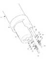
マニピュレータ4は、例えば、オーバーチューブ7のルーメン8内に挿入される軟性の挿入部10と、該挿入部10の先端に設けられた1以上の関節11,12を有する可動部13と、可動部13の先端に設けられた処置部3と、挿入部10の基端に設けられ図示しないワイヤによって可動部13を駆動する駆動部14とを備えている。 The
制御部5は、図3に示されるように、操作者によって操作される操作部15を介して入力された操作入力に基づいて駆動部14を動作させる制御信号を生成する制御信号生成部(制御部)16と、該制御信号生成部16により生成された制御信号に基づいて、マニピュレータ4の疑似画像(補助画像)を生成するとともに、生成した疑似画像を内視鏡2による撮影により取得された実画像上に重畳した合成画像を生成する画像生成部17と、内視鏡2により取得された実画像を処理してマニピュレータ4に加わる外力を検出する画像処理部(外力検出部)18とを備えている。 As shown in FIG. 3, the
画像生成部17は、制御信号に基づいて、運動学方程式からマニピュレータ4の各関節11,12の位置を算出し、算出された位置に各関節11,12を配置したマニピュレータ4および処置部3の形状を表す疑似画像をコンピュータグラフィックにより生成するようになっている。
画像処理部18は、内視鏡2により取得された実画像を画像処理して、実画像上に存在するマニピュレータ4の各関節11,12の位置を抽出し、抽出されたマニピュレータ4の各関節11,12の位置と、画像生成部17により算出されたマニピュレータ4の各関節11,12の位置との差分を算出するようになっている。画像処理部18は、算出されたいずれかの関節11,12の位置の差分の大きさによって、外力の大きさを検出して出力するようになっている。The
The
そして、本実施形態に係る医療用マニピュレータシステム1においては、画像生成部17は、画像処理部18から出力された、マニピュレータ4にかかる外力の大きさに応じて、マニピュレータ4の疑似画像の透明度を変化させるようになっている。
すなわち、画像生成部17は、画像処理部18から出力された外力の大きさを閾値によって複数段階に選別し、最も小さいと判断される場合には、画像生成部17は、疑似画像の透明度を最も高くし、外力の大きさが大きくなるにつれて、疑似画像の透明度を低くするように変化させるようになっている。In the medical manipulator system 1 according to the present embodiment, the
That is, the
このように構成された本実施形態に係る医療用マニピュレータシステム1の作用について以下に説明する。
本実施形態に係る医療用マニピュレータシステム1を用いて患者の体内の患部Xを処置するには、先端を体内に挿入したオーバーチューブ7のルーメン8,9を介して、内視鏡2およびマニピュレータ4を挿入し、オーバーチューブ7の先端から露出させる。The operation of the medical manipulator system 1 according to this embodiment configured as described above will be described below.
In order to treat the affected part X in the patient's body using the medical manipulator system 1 according to the present embodiment, the
内視鏡2の視野範囲内に患部Xを配置すると、内視鏡2により取得された実画像が表示部6に表示される。マニピュレータ4を挿入して、先端を内視鏡2の視野範囲内に配置することにより、マニピュレータ4の先端が表示部6に表示されるので、操作者は、表示部6を見ながら操作部15を操作することにより、マニピュレータ4を動作させて、患部Xを処置することができる。 When the affected part X is disposed within the visual field range of the
操作部15が操作されて操作入力が入力されると、制御信号生成部16によって制御信号が生成され、駆動部14の作動によってマニピュレータ4の可動部13が作動させられるとともに、画像生成部17によって、制御信号に基づいてマニピュレータ4の疑似画像が生成される。
この場合において、マニピュレータ4の先端の処置部3が患部Xに接触していない状態、あるいは、マニピュレータ4の各部が体内の組織等に接触していない場合には、マニピュレータ4には大きな外力が作用しておらず、図4に示されるように、実画像上のマニピュレータ4と、制御信号から生成したマニピュレータ4の疑似画像とはほぼ同じ位置に表示される。When the
In this case, when the
このため、画像処理部18において算出される、実画像上のマニピュレータ4の位置と疑似画像のマニピュレータ4の位置との差分はゼロに近い。したがって、画像生成部17は、マニピュレータ4にかかる外力が小さいと判定し、生成した疑似画像の透明度が高く設定され、疑似画像が目立たない表示形態にして、実画像に重畳した合成画像が生成される。
その結果、実画像上のマニピュレータ4に完全に重なる位置に表示される疑似画像が実画像を遮らないので、処置の邪魔になることがない。For this reason, the difference between the position of the
As a result, the pseudo image displayed at a position that completely overlaps the
一方、処置中にマニピュレータ4の先端の処置部3が患部Xに接触した状態で、マニピュレータ4を動作させると、患部Xからマニピュレータ4が受ける外力が増大する。このため、画像処理部18において算出される、実画像上のマニピュレータ4の位置と疑似画像のマニピュレータ4の位置との差分が図5および図6に示されるように、増大していく。 On the other hand, when the
したがって、画像生成部17は、マニピュレータ4にかかる外力が大きいと判定し、生成した疑似画像の透明度が低く設定され、疑似画像を目立つ表示形態にして、実画像に重畳した合成画像が生成される。その結果、透明度の低い疑似画像が、実画像上のマニピュレータ4からずれた位置に表示され、操作者に、マニピュレータ4にかかる外力が増大したことを認識させることができる。 Therefore, the
このように、本実施形態に係る医療用マニピュレータシステム1によれば、疑似画像の表示態様を変化させることにより、マニピュレータ4にかかる外力が小さいときには実画像を遮らず、外力が大きくなるに従って疑似画像を目立たせることにより、外力が大きくなったことを強調して操作者に知らせることができるという利点がある。 As described above, according to the medical manipulator system 1 according to the present embodiment, by changing the display mode of the pseudo image, when the external force applied to the
なお、本実施形態においては、複数の閾値によって疑似画像の透明度を複数段階に切り替えることとしたが、これに代えて、実画像のマニピュレータ4と疑似画像のマニピュレータ4との位置の差分に応じて連続的に透明度を切り替えることにしてもよい。 In the present embodiment, the transparency of the pseudo image is switched to a plurality of levels by a plurality of thresholds. Instead, according to the position difference between the
また、疑似画像の透明度を変更することに代えて、あるいはこれと共に、疑似画像の色を変化させることにしてもよい。マニピュレータ4にかかる外力が大きい場合には、疑似画像のマニピュレータ4を目立つ色に変えていき、外力が小さい場合には目立たない色に変えていくことにしてもよい。
例えば、赤色の多い体内の生体組織に対して目立つ色としては、赤の補色である緑色の強度を大きくして行くことにより、疑似画像を目立たせることができる。Further, instead of changing the transparency of the pseudo image, or together with this, the color of the pseudo image may be changed. When the external force applied to the
For example, as a color that stands out with respect to a body tissue with a lot of red, a pseudo image can be made conspicuous by increasing the intensity of green, which is a complementary color of red.
また、疑似画像として、マニピュレータ4の輪郭あるいはマニピュレータ4の骨格を表す線画を採用する場合には、マニピュレータ4にかかる外力の大きさに応じて線の透明度や線の色を変化させることにしてもよいし、外力が大きいほど線を太くすることにしてもよい。 Further, when a line drawing representing the outline of the
また、表示部6に表示される部分のマニピュレータ4の疑似画像を生成して、その疑似画像全体の表示形態を変更することとしたが、これに代えて、関節11,12毎に外力の大きさを判断して、関節11,12毎に表示形態を変更することにしてもよい。
また、外力のかかっている方向に矢印を表示し、外力の大きさに応じて矢印の長さや太さを変更することにしてもよい。In addition, a pseudo image of the
Further, an arrow may be displayed in the direction in which the external force is applied, and the length and thickness of the arrow may be changed according to the magnitude of the external force.
また、本実施形態においては、画像処理部18において、実画像を画像処理して実画像上のマニピュレータ4の位置を抽出し、画像生成部17において生成された疑似画像の位置との差分を算出することによってマニピュレータ4にかかる外力の大きさを検出することとしたが、これに代えて、他の任意の方法によって外力の大きさを検出することにしてもよい。例えば、マニピュレータ4にかかる外力が増大すると、可動部13を駆動しているワイヤの張力が増大するので、その張力の大きさから外力の大きさを推定することにしてもよい。 In the present embodiment, the
また、マニピュレータ4の各関節11,12に角度センサあるいは歪みゲージ等のセンサを配置できる場合には、センサの出力によってマニピュレータ4にかかる外力を検出することにしてもよい。 When sensors such as angle sensors or strain gauges can be arranged at the
次に、本発明の第2の実施形態に係る医療用マニピュレータシステム20について図7を参照して説明する。
本実施形態に係る医療用マニピュレータシステム20は、図7に示されるように、硬性のマニピュレータ21を採用している点で、第1の実施形態の医療用マニピュレータシステム1と異なっている。したがって、本実施形態においては、医療用マニピュレータシステム20の構成について主に説明し、第1の実施形態と共通する構成については、同一の符号を付して説明を省略する。Next, a
The
医療用マニピュレータシステム20は、図7に示されるように、内視鏡2と、マニピュレータ21と、腹腔(体腔)A内の臓器Bを圧排する圧排具22と、圧排具22、内視鏡2およびマニピュレータ21を挿入するトロッカ23と、圧排具22、内視鏡2およびマニピュレータ21の各々の基端部分を体外において保持する多関節の電動アーム24,25,26と、操作者によって操作される操作部15と、制御部5と、表示部6とを備えている。 As shown in FIG. 7, the
マニピュレータ21は、腹腔A内に挿入可能な細長い挿入部28と、可動部13と、駆動部14とを備えている。
制御部5の制御信号生成部16は、操作部15に入力された操作入力に基づいて電動アーム24,25,26の関節を動作させる制御信号を生成するようになっている。The
The control
操作者によって操作部15に操作入力が入力されると、その操作入力に対応する信号が制御部5の制御信号生成部16へ送信され、制御信号生成部16が受信した信号に基づいて関節を動作させる制御信号を生成し、生成された制御信号に基づいて電動アーム24,25,26が作動するようになっている。これにより、操作者は、体腔内に挿入されている圧排具22、内視鏡2およびマニピュレータ21を、操作部15を介して遠隔操作することができるようになっている。 When the operator inputs an operation input to the
さらに、制御信号生成部16は、電動アーム24,25,26に設けられた、各関節の回転角度を検出する図示しないエンコーダから検出値を受信し、受信したエンコーダの検出値に基づいて体腔内における圧排具22、内視鏡2およびマニピュレータ21の位置および姿勢を計算する。そして、制御信号生成部16は、算出した内視鏡2およびマニピュレータ21の位置および姿勢に基づいて圧排具22を移動させるように、該圧排具22を保持している電動アーム24の関節を動作させる制御信号を生成する。具体的には、制御信号生成部16は、内視鏡2およびマニピュレータ21が圧排具22へ接近して該圧排具22との間の距離が所定の閾値未満になったときに、圧排具22を内視鏡2またはマニピュレータ21から遠ざける方向へ移動させるように、電動アーム24の関節を動作させる制御信号を生成する。 Further, the control
このように構成された医療用マニピュレータシステム20によれば、腹腔A内の内視鏡2およびマニピュレータ21を操作して処置を行っている最中にマニピュレータ21が圧排具22に近づくと、圧排具22がマニピュレータ21から遠ざかるように自動的に移動することによってマニピュレータ21の近傍に位置していた臓器Bがさらに圧排され、マニピュレータ21の処置空間が新たに確保される。同様に、内視鏡2が圧排具22に近づくと、圧排具22が内視鏡2から遠ざかるように自動的に移動して内視鏡2の視野が確保される。このように、圧排具22と同時に使用される他の医療器具の動作と協調するように圧排具22を移動させることによって、手術のさらなる効率化を図ることができるという利点がある。 According to the
この場合において、本実施形態に係る医療用マニピュレータシステムによれば、画像生成部17によって、制御信号に基づいてマニピュレータ21および圧排具22の疑似画像が生成される。そして、画像処理部18において算出される、実画像上のマニピュレータ21および圧排具22の位置と疑似画像のマニピュレータ21および圧排具22の位置との差分に基づいて疑似画像の透明度が設定される。 In this case, according to the medical manipulator system according to the present embodiment, the
その結果、実画像上のマニピュレータ21および圧排具22に完全に重なる場合には透明度が高く設定されて、疑似画像が実画像を遮らないので、処置の邪魔になることがない。逆に、処置中にマニピュレータ21および圧排具22の先端等が患部Xに接触した状態で、マニピュレータ21および圧排具22を動作させると、患部Xからマニピュレータ21および圧排具22が受ける外力が増大する。このため、画像処理部18において算出される、実画像上のマニピュレータ21および圧排具22の位置と疑似画像のマニピュレータ21および圧排具22の位置との差分が増大していく。 As a result, when it completely overlaps the
この場合には、画像生成部17は、マニピュレータ21および圧排具22にかかる外力が大きいと判定し、生成した疑似画像の透明度を低く設定し、疑似画像を目立つ表示形態にして、実画像に重畳した合成画像を生成する。その結果、透明度の低い疑似画像が、実画像上のマニピュレータ21および圧排具22からずれた位置に表示され、操作者に、マニピュレータ21および圧排具22にかかる外力が増大したことを認識させることができる。 In this case, the
1,20 医療用マニピュレータシステム
2 内視鏡
3 処置部
4,21 マニピュレータ
22 圧排具(マニピュレータ)
6 表示部
16 制御信号生成部(制御部)
17 画像生成部
18 画像処理部(外力検出部)DESCRIPTION OF
6
17
Claims (8)
Translated fromJapanese該マニピュレータを制御する制御部と、
前記マニピュレータによる前記処置部の処置状態を撮影する内視鏡と、
前記マニピュレータに加わる外力を検出する外力検出部と、
前記制御部による制御信号に基づく位置に前記マニピュレータの疑似画像を生成し、前記内視鏡により取得される実画像に重畳した合成画像を生成する画像生成部と、
該画像生成部により生成された合成画像を表示する表示部とを備え、
前記画像生成部が、前記外力検出部により検出された外力の大きさが大きいほど、前記疑似画像の透明度を低くするように前記疑似画像の表示態様を変化させる医療用マニピュレータシステム。A manipulator having a treatment portion at the tip;
A control unit for controlling the manipulator;
An endoscope for photographing the treatment state of the treatment section by the manipulator;
An external force detector for detecting an external force applied to the manipulator;
An image generation unit that generates a pseudo image of the manipulator at a position based on a control signal by the control unit, and generates a composite image superimposed on a real image acquired by the endoscope;
A display unit for displaying the composite image generated by the image generation unit,
The image generation unit, the larger the magnitude of the detected external force by the force detecting unit, themedical Ryoyo manipulatorsystem Ru changing the display mode of the pseudo-image to lower the transparency of the pseudo image.
該マニピュレータを制御する制御部と、
前記マニピュレータによる前記処置部の処置状態を撮影する内視鏡と、
前記マニピュレータに加わる外力を検出する外力検出部と、
前記制御部による制御信号に基づく位置に前記マニピュレータの疑似画像を生成し、前記内視鏡により取得される実画像に重畳した合成画像を生成する画像生成部と、
該画像生成部により生成された合成画像を表示する表示部とを備え、
前記画像生成部が、前記外力検出部により検出された外力の大きさが大きいほど、前記疑似画像の色を目立つ色に変更するように前記疑似画像の表示態様を変化させる医療用マニピュレータシステム。A manipulator having a treatment portion at the tip;
A control unit for controlling the manipulator;
An endoscope for photographing the treatment state of the treatment section by the manipulator;
An external force detector for detecting an external force applied to the manipulator;
An image generation unit that generates a pseudo image of the manipulator at a position based on a control signal by the control unit, and generates a composite image superimposed on an actual image acquired by the endoscope;
A display unit for displaying the composite image generated by the image generation unit,
The image generation unit is, the more the larger the detected magnitude of the external force by the external force detecting unit, the false image the false imagemedical Ryoyo manipulatorsystem Ru changing the display mode of such change in a noticeable color color .
該マニピュレータを制御する制御部と、
前記マニピュレータによる前記処置部の処置状態を撮影する内視鏡と、
前記マニピュレータに加わる外力を検出する外力検出部と、
前記制御部による制御信号に基づく位置に前記マニピュレータの疑似画像を生成し、前記内視鏡により取得される実画像に重畳した合成画像を生成する画像生成部と、
該画像生成部により生成された合成画像を表示する表示部とを備え、
前記画像生成部が、前記疑似画像を線画により生成し、前記外力検出部により検出された外力の大きさが大きいほど、前記疑似画像の線を太く変更するように前記疑似画像の表示態様を変化させる医療用マニピュレータシステム。A manipulator having a treatment portion at the tip;
A control unit for controlling the manipulator;
An endoscope for photographing the treatment state of the treatment section by the manipulator;
An external force detector for detecting an external force applied to the manipulator;
An image generation unit that generates a pseudo image of the manipulator at a position based on a control signal by the control unit, and generates a composite image superimposed on an actual image acquired by the endoscope;
A display unit for displaying the composite image generated by the image generation unit,
The image generation unit generates the pseudo image by line drawing, and the display mode of the pseudo image is changed so that the line of the pseudo image is changed thicker as the magnitude of the external force detected by the external force detection unit is larger.medical Ryoyo manipulator systemthat Ru is.
前記外力検出部が、前記ワイヤの張力に基づいて、前記外力を検出する請求項1から請求項3のいずれかに記載の医療用マニピュレータシステム。The manipulator is driven by a wire;
The medical manipulator system according to any one of claims 1 to3 , wherein the external force detection unit detects the external force based on a tension of the wire.
該マニピュレータを制御する制御部と、
前記マニピュレータによる前記処置部の処置状態を撮影する内視鏡と、
前記マニピュレータに加わる外力を検出する外力検出部と、
を備える医療用マニピュレータシステムの作動方法であって、
前記制御部による制御信号に基づく位置に前記マニピュレータの疑似画像を生成する工程と、
前記内視鏡により実画像を取得する工程と、
前記外力検出部により検出された前記外力の大きさに基づいて、前記疑似画像の表示態様を変化させる工程と、
前記疑似画像を前記実画像に重畳した合成画像を生成する工程と、
生成した合成画像を表示部へ送信する工程と、を含み、
前記疑似画像の表示態様を変化させる工程において、前記外力の大きさが大きいほど、前記疑似画像の透明度を低くするように前記疑似画像の表示態様を変化させる医療用マニピュレータシステムの作動方法。A manipulator having a treatment portion at the tip;
A control unit for controlling the manipulator;
An endoscope for photographing the treatment state of the treatment section by the manipulator;
An external force detector for detecting an external force applied to the manipulator;
A method for operating a medical manipulator system comprising:
Generating a pseudo image of the manipulator at a position based on a control signal by the control unit;
Obtaining a real image with the endoscope;
Changing the display mode of the pseudo image based on the magnitude of the external force detected by the external force detector;
Generating a composite image in which the pseudo image is superimposed on the real image;
Transmitting the generated composite image to the display unit,
Wherein in the step of changing the display mode of the pseudo-image, the larger the magnitude of the external force, a method of operating themedical Ryoyo manipulatorsystem Ru changing the display mode of the pseudo-image to lower the transparency of the pseudo image.
該マニピュレータを制御する制御部と、
前記マニピュレータによる前記処置部の処置状態を撮影する内視鏡と、
前記マニピュレータに加わる外力を検出する外力検出部と、
を備える医療用マニピュレータシステムの作動方法であって、
前記制御部による制御信号に基づく位置に前記マニピュレータの疑似画像を生成する工程と、
前記内視鏡により実画像を取得する工程と、
前記外力検出部により検出された前記外力の大きさに基づいて、前記疑似画像の表示態様を変化させる工程と、
前記疑似画像を前記実画像に重畳した合成画像を生成する工程と、
生成した合成画像を表示部へ送信する工程と、を含み、
前記疑似画像の表示態様を変化させる工程において、前記外力の大きさが大きいほど、前記疑似画像の色を目立つ色に変更するように前記疑似画像の表示態様を変化させる医療用マニピュレータシステムの作動方法。A manipulator having a treatment portion at the tip;
A control unit for controlling the manipulator;
An endoscope for photographing the treatment state of the treatment section by the manipulator;
An external force detector for detecting an external force applied to the manipulator;
A method for operating a medical manipulator system comprising:
Generating a pseudo image of the manipulator at a position based on a control signal by the control unit;
Obtaining a real image with the endoscope;
Changing the display mode of the pseudo image based on the magnitude of the external force detected by the external force detector;
Generating a composite image in which the pseudo image is superimposed on the real image;
Transmitting the generated composite image to the display unit,
In the step of changing the display mode of the false image of the external force as the magnitude, of the pseudo-image the false imagemedical Ryoyo manipulatorsystem Ru changing the display mode of such change in a noticeable color color Actuation method.
該マニピュレータを制御する制御部と、
前記マニピュレータによる前記処置部の処置状態を撮影する内視鏡と、
前記マニピュレータに加わる外力を検出する外力検出部と、
を備える医療用マニピュレータシステムの作動方法であって、
前記制御部による制御信号に基づく位置に前記マニピュレータの疑似画像を生成する工程と、
前記内視鏡により実画像を取得する工程と、
前記外力検出部により検出された前記外力の大きさに基づいて、前記疑似画像の表示態様を変化させる工程と、
前記疑似画像を前記実画像に重畳した合成画像を生成する工程と、
生成した合成画像を表示部へ送信する工程と、を含み、
前記疑似画像を線画により生成し、
前記疑似画像の表示態様を変化させる工程において、前記外力の大きさが大きいほど、前記疑似画像の線を太く変更するように前記疑似画像の表示態様を変化させる医療用マニピュレータシステムの作動方法。A manipulator having a treatment portion at the tip;
A control unit for controlling the manipulator;
An endoscope for photographing the treatment state of the treatment section by the manipulator;
An external force detector for detecting an external force applied to the manipulator;
A method for operating a medical manipulator system comprising:
Generating a pseudo image of the manipulator at a position based on a control signal by the control unit;
Obtaining a real image with the endoscope;
Changing the display mode of the pseudo image based on the magnitude of the external force detected by the external force detector;
Generating a composite image in which the pseudo image is superimposed on the real image;
Transmitting the generated composite image to the display unit,
Generating the pseudo image by line drawing;
In the step of changing the display mode of the pseudo image, the larger the magnitude of the external force, the method of operating themedical Ryoyo manipulatorsystem Ru changing the display mode of the pseudo-image to change thicker line of the pseudo image .
Applications Claiming Priority (1)
| Application Number | Priority Date | Filing Date | Title |
|---|---|---|---|
| PCT/JP2016/050974WO2017122322A1 (en) | 2016-01-14 | 2016-01-14 | Medical manipulator system |
Publications (2)
| Publication Number | Publication Date |
|---|---|
| JPWO2017122322A1 JPWO2017122322A1 (en) | 2018-11-29 |
| JP6619456B2true JP6619456B2 (en) | 2019-12-11 |
Family
ID=59312015
Family Applications (1)
| Application Number | Title | Priority Date | Filing Date |
|---|---|---|---|
| JP2017561464AActiveJP6619456B2 (en) | 2016-01-14 | 2016-01-14 | Medical manipulator system and method for operating medical manipulator system |
Country Status (3)
| Country | Link |
|---|---|
| US (1) | US10959787B2 (en) |
| JP (1) | JP6619456B2 (en) |
| WO (1) | WO2017122322A1 (en) |
Families Citing this family (2)
| Publication number | Priority date | Publication date | Assignee | Title |
|---|---|---|---|---|
| JP6867654B2 (en) | 2019-03-15 | 2021-05-12 | リバーフィールド株式会社 | Force display device and force display method for medical robot systems |
| US20240180394A1 (en)* | 2022-12-02 | 2024-06-06 | Arthrex, Inc | System and method for force estimation applied to endoscopes |
Family Cites Families (22)
| Publication number | Priority date | Publication date | Assignee | Title |
|---|---|---|---|---|
| JPH07184923A (en) | 1993-12-28 | 1995-07-25 | Hitachi Ltd | Remote microsurgery support device |
| JP3608448B2 (en) | 1999-08-31 | 2005-01-12 | 株式会社日立製作所 | Treatment device |
| JP2001104333A (en) | 1999-10-07 | 2001-04-17 | Hitachi Ltd | Surgery support device |
| JP2001150368A (en) | 1999-11-24 | 2001-06-05 | Olympus Optical Co Ltd | Manipulator controller |
| US9789608B2 (en) | 2006-06-29 | 2017-10-17 | Intuitive Surgical Operations, Inc. | Synthetic representation of a surgical robot |
| US8971597B2 (en) | 2005-05-16 | 2015-03-03 | Intuitive Surgical Operations, Inc. | Efficient vision and kinematic data fusion for robotic surgical instruments and other applications |
| JP2007029232A (en) | 2005-07-25 | 2007-02-08 | Hitachi Medical Corp | System for supporting endoscopic operation |
| US20090192523A1 (en)* | 2006-06-29 | 2009-07-30 | Intuitive Surgical, Inc. | Synthetic representation of a surgical instrument |
| US10258425B2 (en) | 2008-06-27 | 2019-04-16 | Intuitive Surgical Operations, Inc. | Medical robotic system providing an auxiliary view of articulatable instruments extending out of a distal end of an entry guide |
| US9718190B2 (en) | 2006-06-29 | 2017-08-01 | Intuitive Surgical Operations, Inc. | Tool position and identification indicator displayed in a boundary area of a computer display screen |
| US10008017B2 (en) | 2006-06-29 | 2018-06-26 | Intuitive Surgical Operations, Inc. | Rendering tool information as graphic overlays on displayed images of tools |
| US7831096B2 (en)* | 2006-11-17 | 2010-11-09 | General Electric Company | Medical navigation system with tool and/or implant integration into fluoroscopic image projections and method of use |
| US8594841B2 (en)* | 2008-12-31 | 2013-11-26 | Intuitive Surgical Operations, Inc. | Visual force feedback in a minimally invasive surgical procedure |
| US8374723B2 (en)* | 2008-12-31 | 2013-02-12 | Intuitive Surgical Operations, Inc. | Obtaining force information in a minimally invasive surgical procedure |
| WO2010090059A1 (en)* | 2009-02-03 | 2010-08-12 | オリンパスメディカルシステムズ株式会社 | Manipulator |
| CN104244800B (en)* | 2012-04-19 | 2017-05-17 | 皇家飞利浦有限公司 | Guidance tools to manually steer endoscope using pre-operative and intra-operative 3d images |
| JP6112300B2 (en) | 2013-01-10 | 2017-04-12 | パナソニックIpマネジメント株式会社 | Master-slave robot control device and control method, master-slave robot, and control program |
| JP2015163172A (en) | 2014-02-28 | 2015-09-10 | オリンパス株式会社 | Exclusion device and robot system |
| US20150377613A1 (en)* | 2014-06-30 | 2015-12-31 | Samsung Electronics Co., Ltd. | Systems and methods for reconstructing 3d surfaces of tubular lumens |
| US9947091B2 (en)* | 2015-11-16 | 2018-04-17 | Biosense Webster (Israel) Ltd. | Locally applied transparency for a CT image |
| KR102764213B1 (en)* | 2016-06-30 | 2025-02-07 | 인튜어티브 서지컬 오퍼레이션즈 인코포레이티드 | Graphical user interface for displaying guidance information in a plurality of modes during an image-guided procedure |
| EP4620418A2 (en)* | 2016-06-30 | 2025-09-24 | Intuitive Surgical Operations, Inc. | Graphical user interface for displaying guidance information during an image-guided procedure |
- 2016
- 2016-01-14JPJP2017561464Apatent/JP6619456B2/enactiveActive
- 2016-01-14WOPCT/JP2016/050974patent/WO2017122322A1/ennot_activeCeased
- 2018
- 2018-07-11USUS16/032,153patent/US10959787B2/enactiveActive
Also Published As
| Publication number | Publication date |
|---|---|
| JPWO2017122322A1 (en) | 2018-11-29 |
| WO2017122322A1 (en) | 2017-07-20 |
| US20180325607A1 (en) | 2018-11-15 |
| US10959787B2 (en) | 2021-03-30 |
Similar Documents
| Publication | Publication Date | Title |
|---|---|---|
| US12274514B2 (en) | Graphical user interface for displaying guidance information during an image-guided procedure | |
| CN110325093B (en) | Medical arm system, control device, and control method | |
| US8497898B2 (en) | Endoscope system and low visibility determining method | |
| JP5750122B2 (en) | Robot endoscope operation control method and system | |
| JP4744595B2 (en) | Endoscopic surgical instrument | |
| CN110769737B (en) | Insertion aid, method of operation, and endoscopic device including insertion aid | |
| CN111465340B (en) | Recommended operation presentation system, recommended operation presentation control device, and recommended operation presentation control method | |
| JP6033444B2 (en) | Robot-assisted surgery system and its operation method | |
| US20170165013A1 (en) | Systems and methods for offscreen indication of instruments in a teleoperational medical system | |
| JP6753081B2 (en) | Endoscopic surgery system, image processing method and medical observation system | |
| KR20140115575A (en) | Surgical robot system and method for controlling the same | |
| JP5826727B2 (en) | Medical system | |
| WO2015005072A1 (en) | Surgical assistance robot | |
| CN113905652A (en) | Medical observation system, control device and control method | |
| JP6619456B2 (en) | Medical manipulator system and method for operating medical manipulator system | |
| CN105407826A (en) | Control method of medical master-slave system | |
| US20170071450A1 (en) | Endoscope system and method of operating the same | |
| KR20200132174A (en) | AR colonoscopy system and method for monitoring by using the same | |
| KR20150105803A (en) | Three dimension endoscope system using giro sensor |
Legal Events
| Date | Code | Title | Description |
|---|---|---|---|
| A521 | Request for written amendment filed | Free format text:JAPANESE INTERMEDIATE CODE: A523 Effective date:20180712 | |
| A621 | Written request for application examination | Free format text:JAPANESE INTERMEDIATE CODE: A621 Effective date:20180712 | |
| A131 | Notification of reasons for refusal | Free format text:JAPANESE INTERMEDIATE CODE: A131 Effective date:20190611 | |
| A521 | Request for written amendment filed | Free format text:JAPANESE INTERMEDIATE CODE: A523 Effective date:20190807 | |
| A131 | Notification of reasons for refusal | Free format text:JAPANESE INTERMEDIATE CODE: A131 Effective date:20190827 | |
| A521 | Request for written amendment filed | Free format text:JAPANESE INTERMEDIATE CODE: A523 Effective date:20191010 | |
| TRDD | Decision of grant or rejection written | ||
| A01 | Written decision to grant a patent or to grant a registration (utility model) | Free format text:JAPANESE INTERMEDIATE CODE: A01 Effective date:20191029 | |
| A61 | First payment of annual fees (during grant procedure) | Free format text:JAPANESE INTERMEDIATE CODE: A61 Effective date:20191114 | |
| R151 | Written notification of patent or utility model registration | Ref document number:6619456 Country of ref document:JP Free format text:JAPANESE INTERMEDIATE CODE: R151 | |
| R250 | Receipt of annual fees | Free format text:JAPANESE INTERMEDIATE CODE: R250 | |
| R250 | Receipt of annual fees | Free format text:JAPANESE INTERMEDIATE CODE: R250 | |
| R250 | Receipt of annual fees | Free format text:JAPANESE INTERMEDIATE CODE: R250 |