JP6616902B2 - Electric vehicle drive circuit and control method thereof - Google Patents
Electric vehicle drive circuit and control method thereofDownload PDFInfo
- Publication number
- JP6616902B2 JP6616902B2JP2018529548AJP2018529548AJP6616902B2JP 6616902 B2JP6616902 B2JP 6616902B2JP 2018529548 AJP2018529548 AJP 2018529548AJP 2018529548 AJP2018529548 AJP 2018529548AJP 6616902 B2JP6616902 B2JP 6616902B2
- Authority
- JP
- Japan
- Prior art keywords
- contactor
- control signal
- electric vehicle
- resistor
- voltage
- Prior art date
- Legal status (The legal status is an assumption and is not a legal conclusion. Google has not performed a legal analysis and makes no representation as to the accuracy of the status listed.)
- Active
Links
Images


Classifications
- B—PERFORMING OPERATIONS; TRANSPORTING
- B60—VEHICLES IN GENERAL
- B60L—PROPULSION OF ELECTRICALLY-PROPELLED VEHICLES; SUPPLYING ELECTRIC POWER FOR AUXILIARY EQUIPMENT OF ELECTRICALLY-PROPELLED VEHICLES; ELECTRODYNAMIC BRAKE SYSTEMS FOR VEHICLES IN GENERAL; MAGNETIC SUSPENSION OR LEVITATION FOR VEHICLES; MONITORING OPERATING VARIABLES OF ELECTRICALLY-PROPELLED VEHICLES; ELECTRIC SAFETY DEVICES FOR ELECTRICALLY-PROPELLED VEHICLES
- B60L58/00—Methods or circuit arrangements for monitoring or controlling batteries or fuel cells, specially adapted for electric vehicles
- B60L58/10—Methods or circuit arrangements for monitoring or controlling batteries or fuel cells, specially adapted for electric vehicles for monitoring or controlling batteries
- B—PERFORMING OPERATIONS; TRANSPORTING
- B60—VEHICLES IN GENERAL
- B60L—PROPULSION OF ELECTRICALLY-PROPELLED VEHICLES; SUPPLYING ELECTRIC POWER FOR AUXILIARY EQUIPMENT OF ELECTRICALLY-PROPELLED VEHICLES; ELECTRODYNAMIC BRAKE SYSTEMS FOR VEHICLES IN GENERAL; MAGNETIC SUSPENSION OR LEVITATION FOR VEHICLES; MONITORING OPERATING VARIABLES OF ELECTRICALLY-PROPELLED VEHICLES; ELECTRIC SAFETY DEVICES FOR ELECTRICALLY-PROPELLED VEHICLES
- B60L3/00—Electric devices on electrically-propelled vehicles for safety purposes; Monitoring operating variables, e.g. speed, deceleration or energy consumption
- B60L3/06—Limiting the traction current under mechanical overload conditions
- B—PERFORMING OPERATIONS; TRANSPORTING
- B60—VEHICLES IN GENERAL
- B60L—PROPULSION OF ELECTRICALLY-PROPELLED VEHICLES; SUPPLYING ELECTRIC POWER FOR AUXILIARY EQUIPMENT OF ELECTRICALLY-PROPELLED VEHICLES; ELECTRODYNAMIC BRAKE SYSTEMS FOR VEHICLES IN GENERAL; MAGNETIC SUSPENSION OR LEVITATION FOR VEHICLES; MONITORING OPERATING VARIABLES OF ELECTRICALLY-PROPELLED VEHICLES; ELECTRIC SAFETY DEVICES FOR ELECTRICALLY-PROPELLED VEHICLES
- B60L3/00—Electric devices on electrically-propelled vehicles for safety purposes; Monitoring operating variables, e.g. speed, deceleration or energy consumption
- B60L3/0023—Detecting, eliminating, remedying or compensating for drive train abnormalities, e.g. failures within the drive train
- B60L3/0069—Detecting, eliminating, remedying or compensating for drive train abnormalities, e.g. failures within the drive train relating to the isolation, e.g. ground fault or leak current
- B—PERFORMING OPERATIONS; TRANSPORTING
- B60—VEHICLES IN GENERAL
- B60L—PROPULSION OF ELECTRICALLY-PROPELLED VEHICLES; SUPPLYING ELECTRIC POWER FOR AUXILIARY EQUIPMENT OF ELECTRICALLY-PROPELLED VEHICLES; ELECTRODYNAMIC BRAKE SYSTEMS FOR VEHICLES IN GENERAL; MAGNETIC SUSPENSION OR LEVITATION FOR VEHICLES; MONITORING OPERATING VARIABLES OF ELECTRICALLY-PROPELLED VEHICLES; ELECTRIC SAFETY DEVICES FOR ELECTRICALLY-PROPELLED VEHICLES
- B60L3/00—Electric devices on electrically-propelled vehicles for safety purposes; Monitoring operating variables, e.g. speed, deceleration or energy consumption
- B60L3/0092—Electric devices on electrically-propelled vehicles for safety purposes; Monitoring operating variables, e.g. speed, deceleration or energy consumption with use of redundant elements for safety purposes
- B—PERFORMING OPERATIONS; TRANSPORTING
- B60—VEHICLES IN GENERAL
- B60L—PROPULSION OF ELECTRICALLY-PROPELLED VEHICLES; SUPPLYING ELECTRIC POWER FOR AUXILIARY EQUIPMENT OF ELECTRICALLY-PROPELLED VEHICLES; ELECTRODYNAMIC BRAKE SYSTEMS FOR VEHICLES IN GENERAL; MAGNETIC SUSPENSION OR LEVITATION FOR VEHICLES; MONITORING OPERATING VARIABLES OF ELECTRICALLY-PROPELLED VEHICLES; ELECTRIC SAFETY DEVICES FOR ELECTRICALLY-PROPELLED VEHICLES
- B60L3/00—Electric devices on electrically-propelled vehicles for safety purposes; Monitoring operating variables, e.g. speed, deceleration or energy consumption
- B60L3/04—Cutting off the power supply under fault conditions
- B—PERFORMING OPERATIONS; TRANSPORTING
- B60—VEHICLES IN GENERAL
- B60L—PROPULSION OF ELECTRICALLY-PROPELLED VEHICLES; SUPPLYING ELECTRIC POWER FOR AUXILIARY EQUIPMENT OF ELECTRICALLY-PROPELLED VEHICLES; ELECTRODYNAMIC BRAKE SYSTEMS FOR VEHICLES IN GENERAL; MAGNETIC SUSPENSION OR LEVITATION FOR VEHICLES; MONITORING OPERATING VARIABLES OF ELECTRICALLY-PROPELLED VEHICLES; ELECTRIC SAFETY DEVICES FOR ELECTRICALLY-PROPELLED VEHICLES
- B60L50/00—Electric propulsion with power supplied within the vehicle
- B60L50/50—Electric propulsion with power supplied within the vehicle using propulsion power supplied by batteries or fuel cells
- B60L50/60—Electric propulsion with power supplied within the vehicle using propulsion power supplied by batteries or fuel cells using power supplied by batteries
- B—PERFORMING OPERATIONS; TRANSPORTING
- B60—VEHICLES IN GENERAL
- B60L—PROPULSION OF ELECTRICALLY-PROPELLED VEHICLES; SUPPLYING ELECTRIC POWER FOR AUXILIARY EQUIPMENT OF ELECTRICALLY-PROPELLED VEHICLES; ELECTRODYNAMIC BRAKE SYSTEMS FOR VEHICLES IN GENERAL; MAGNETIC SUSPENSION OR LEVITATION FOR VEHICLES; MONITORING OPERATING VARIABLES OF ELECTRICALLY-PROPELLED VEHICLES; ELECTRIC SAFETY DEVICES FOR ELECTRICALLY-PROPELLED VEHICLES
- B60L53/00—Methods of charging batteries, specially adapted for electric vehicles; Charging stations or on-board charging equipment therefor; Exchange of energy storage elements in electric vehicles
- B60L53/20—Methods of charging batteries, specially adapted for electric vehicles; Charging stations or on-board charging equipment therefor; Exchange of energy storage elements in electric vehicles characterised by converters located in the vehicle
- B—PERFORMING OPERATIONS; TRANSPORTING
- B60—VEHICLES IN GENERAL
- B60L—PROPULSION OF ELECTRICALLY-PROPELLED VEHICLES; SUPPLYING ELECTRIC POWER FOR AUXILIARY EQUIPMENT OF ELECTRICALLY-PROPELLED VEHICLES; ELECTRODYNAMIC BRAKE SYSTEMS FOR VEHICLES IN GENERAL; MAGNETIC SUSPENSION OR LEVITATION FOR VEHICLES; MONITORING OPERATING VARIABLES OF ELECTRICALLY-PROPELLED VEHICLES; ELECTRIC SAFETY DEVICES FOR ELECTRICALLY-PROPELLED VEHICLES
- B60L53/00—Methods of charging batteries, specially adapted for electric vehicles; Charging stations or on-board charging equipment therefor; Exchange of energy storage elements in electric vehicles
- B60L53/50—Charging stations characterised by energy-storage or power-generation means
- B60L53/53—Batteries
- B—PERFORMING OPERATIONS; TRANSPORTING
- B60—VEHICLES IN GENERAL
- B60L—PROPULSION OF ELECTRICALLY-PROPELLED VEHICLES; SUPPLYING ELECTRIC POWER FOR AUXILIARY EQUIPMENT OF ELECTRICALLY-PROPELLED VEHICLES; ELECTRODYNAMIC BRAKE SYSTEMS FOR VEHICLES IN GENERAL; MAGNETIC SUSPENSION OR LEVITATION FOR VEHICLES; MONITORING OPERATING VARIABLES OF ELECTRICALLY-PROPELLED VEHICLES; ELECTRIC SAFETY DEVICES FOR ELECTRICALLY-PROPELLED VEHICLES
- B60L53/00—Methods of charging batteries, specially adapted for electric vehicles; Charging stations or on-board charging equipment therefor; Exchange of energy storage elements in electric vehicles
- B60L53/50—Charging stations characterised by energy-storage or power-generation means
- B60L53/55—Capacitors
- B—PERFORMING OPERATIONS; TRANSPORTING
- B60—VEHICLES IN GENERAL
- B60L—PROPULSION OF ELECTRICALLY-PROPELLED VEHICLES; SUPPLYING ELECTRIC POWER FOR AUXILIARY EQUIPMENT OF ELECTRICALLY-PROPELLED VEHICLES; ELECTRODYNAMIC BRAKE SYSTEMS FOR VEHICLES IN GENERAL; MAGNETIC SUSPENSION OR LEVITATION FOR VEHICLES; MONITORING OPERATING VARIABLES OF ELECTRICALLY-PROPELLED VEHICLES; ELECTRIC SAFETY DEVICES FOR ELECTRICALLY-PROPELLED VEHICLES
- B60L58/00—Methods or circuit arrangements for monitoring or controlling batteries or fuel cells, specially adapted for electric vehicles
- B60L58/10—Methods or circuit arrangements for monitoring or controlling batteries or fuel cells, specially adapted for electric vehicles for monitoring or controlling batteries
- B60L58/18—Methods or circuit arrangements for monitoring or controlling batteries or fuel cells, specially adapted for electric vehicles for monitoring or controlling batteries of two or more battery modules
- B60L58/21—Methods or circuit arrangements for monitoring or controlling batteries or fuel cells, specially adapted for electric vehicles for monitoring or controlling batteries of two or more battery modules having the same nominal voltage
- G—PHYSICS
- G01—MEASURING; TESTING
- G01R—MEASURING ELECTRIC VARIABLES; MEASURING MAGNETIC VARIABLES
- G01R19/00—Arrangements for measuring currents or voltages or for indicating presence or sign thereof
- G01R19/165—Indicating that current or voltage is either above or below a predetermined value or within or outside a predetermined range of values
- G01R19/16533—Indicating that current or voltage is either above or below a predetermined value or within or outside a predetermined range of values characterised by the application
- G01R19/16538—Indicating that current or voltage is either above or below a predetermined value or within or outside a predetermined range of values characterised by the application in AC or DC supplies
- G01R19/16542—Indicating that current or voltage is either above or below a predetermined value or within or outside a predetermined range of values characterised by the application in AC or DC supplies for batteries
- G—PHYSICS
- G01—MEASURING; TESTING
- G01R—MEASURING ELECTRIC VARIABLES; MEASURING MAGNETIC VARIABLES
- G01R31/00—Arrangements for testing electric properties; Arrangements for locating electric faults; Arrangements for electrical testing characterised by what is being tested not provided for elsewhere
- G01R31/005—Testing of electric installations on transport means
- G01R31/006—Testing of electric installations on transport means on road vehicles, e.g. automobiles or trucks
- G—PHYSICS
- G01—MEASURING; TESTING
- G01R—MEASURING ELECTRIC VARIABLES; MEASURING MAGNETIC VARIABLES
- G01R31/00—Arrangements for testing electric properties; Arrangements for locating electric faults; Arrangements for electrical testing characterised by what is being tested not provided for elsewhere
- G01R31/36—Arrangements for testing, measuring or monitoring the electrical condition of accumulators or electric batteries, e.g. capacity or state of charge [SoC]
- G01R31/364—Battery terminal connectors with integrated measuring arrangements
- H—ELECTRICITY
- H01—ELECTRIC ELEMENTS
- H01M—PROCESSES OR MEANS, e.g. BATTERIES, FOR THE DIRECT CONVERSION OF CHEMICAL ENERGY INTO ELECTRICAL ENERGY
- H01M10/00—Secondary cells; Manufacture thereof
- H01M10/42—Methods or arrangements for servicing or maintenance of secondary cells or secondary half-cells
- H01M10/48—Accumulators combined with arrangements for measuring, testing or indicating the condition of cells, e.g. the level or density of the electrolyte
- H—ELECTRICITY
- H02—GENERATION; CONVERSION OR DISTRIBUTION OF ELECTRIC POWER
- H02J—CIRCUIT ARRANGEMENTS OR SYSTEMS FOR SUPPLYING OR DISTRIBUTING ELECTRIC POWER; SYSTEMS FOR STORING ELECTRIC ENERGY
- H02J7/00—Circuit arrangements for charging or depolarising batteries or for supplying loads from batteries
- H02J7/34—Parallel operation in networks using both storage and other DC sources, e.g. providing buffering
- H02J7/345—Parallel operation in networks using both storage and other DC sources, e.g. providing buffering using capacitors as storage or buffering devices
- B—PERFORMING OPERATIONS; TRANSPORTING
- B60—VEHICLES IN GENERAL
- B60L—PROPULSION OF ELECTRICALLY-PROPELLED VEHICLES; SUPPLYING ELECTRIC POWER FOR AUXILIARY EQUIPMENT OF ELECTRICALLY-PROPELLED VEHICLES; ELECTRODYNAMIC BRAKE SYSTEMS FOR VEHICLES IN GENERAL; MAGNETIC SUSPENSION OR LEVITATION FOR VEHICLES; MONITORING OPERATING VARIABLES OF ELECTRICALLY-PROPELLED VEHICLES; ELECTRIC SAFETY DEVICES FOR ELECTRICALLY-PROPELLED VEHICLES
- B60L2240/00—Control parameters of input or output; Target parameters
- B60L2240/10—Vehicle control parameters
- B60L2240/12—Speed
- B—PERFORMING OPERATIONS; TRANSPORTING
- B60—VEHICLES IN GENERAL
- B60L—PROPULSION OF ELECTRICALLY-PROPELLED VEHICLES; SUPPLYING ELECTRIC POWER FOR AUXILIARY EQUIPMENT OF ELECTRICALLY-PROPELLED VEHICLES; ELECTRODYNAMIC BRAKE SYSTEMS FOR VEHICLES IN GENERAL; MAGNETIC SUSPENSION OR LEVITATION FOR VEHICLES; MONITORING OPERATING VARIABLES OF ELECTRICALLY-PROPELLED VEHICLES; ELECTRIC SAFETY DEVICES FOR ELECTRICALLY-PROPELLED VEHICLES
- B60L2270/00—Problem solutions or means not otherwise provided for
- B60L2270/20—Inrush current reduction, i.e. avoiding high currents when connecting the battery
- B—PERFORMING OPERATIONS; TRANSPORTING
- B60—VEHICLES IN GENERAL
- B60Y—INDEXING SCHEME RELATING TO ASPECTS CROSS-CUTTING VEHICLE TECHNOLOGY
- B60Y2200/00—Type of vehicle
- B60Y2200/90—Vehicles comprising electric prime movers
- B60Y2200/91—Electric vehicles
- H—ELECTRICITY
- H01—ELECTRIC ELEMENTS
- H01M—PROCESSES OR MEANS, e.g. BATTERIES, FOR THE DIRECT CONVERSION OF CHEMICAL ENERGY INTO ELECTRICAL ENERGY
- H01M2220/00—Batteries for particular applications
- H01M2220/20—Batteries in motive systems, e.g. vehicle, ship, plane
- Y—GENERAL TAGGING OF NEW TECHNOLOGICAL DEVELOPMENTS; GENERAL TAGGING OF CROSS-SECTIONAL TECHNOLOGIES SPANNING OVER SEVERAL SECTIONS OF THE IPC; TECHNICAL SUBJECTS COVERED BY FORMER USPC CROSS-REFERENCE ART COLLECTIONS [XRACs] AND DIGESTS
- Y02—TECHNOLOGIES OR APPLICATIONS FOR MITIGATION OR ADAPTATION AGAINST CLIMATE CHANGE
- Y02E—REDUCTION OF GREENHOUSE GAS [GHG] EMISSIONS, RELATED TO ENERGY GENERATION, TRANSMISSION OR DISTRIBUTION
- Y02E60/00—Enabling technologies; Technologies with a potential or indirect contribution to GHG emissions mitigation
- Y02E60/10—Energy storage using batteries
- Y—GENERAL TAGGING OF NEW TECHNOLOGICAL DEVELOPMENTS; GENERAL TAGGING OF CROSS-SECTIONAL TECHNOLOGIES SPANNING OVER SEVERAL SECTIONS OF THE IPC; TECHNICAL SUBJECTS COVERED BY FORMER USPC CROSS-REFERENCE ART COLLECTIONS [XRACs] AND DIGESTS
- Y02—TECHNOLOGIES OR APPLICATIONS FOR MITIGATION OR ADAPTATION AGAINST CLIMATE CHANGE
- Y02T—CLIMATE CHANGE MITIGATION TECHNOLOGIES RELATED TO TRANSPORTATION
- Y02T10/00—Road transport of goods or passengers
- Y02T10/60—Other road transportation technologies with climate change mitigation effect
- Y02T10/70—Energy storage systems for electromobility, e.g. batteries
- Y—GENERAL TAGGING OF NEW TECHNOLOGICAL DEVELOPMENTS; GENERAL TAGGING OF CROSS-SECTIONAL TECHNOLOGIES SPANNING OVER SEVERAL SECTIONS OF THE IPC; TECHNICAL SUBJECTS COVERED BY FORMER USPC CROSS-REFERENCE ART COLLECTIONS [XRACs] AND DIGESTS
- Y02—TECHNOLOGIES OR APPLICATIONS FOR MITIGATION OR ADAPTATION AGAINST CLIMATE CHANGE
- Y02T—CLIMATE CHANGE MITIGATION TECHNOLOGIES RELATED TO TRANSPORTATION
- Y02T10/00—Road transport of goods or passengers
- Y02T10/60—Other road transportation technologies with climate change mitigation effect
- Y02T10/7072—Electromobility specific charging systems or methods for batteries, ultracapacitors, supercapacitors or double-layer capacitors
- Y—GENERAL TAGGING OF NEW TECHNOLOGICAL DEVELOPMENTS; GENERAL TAGGING OF CROSS-SECTIONAL TECHNOLOGIES SPANNING OVER SEVERAL SECTIONS OF THE IPC; TECHNICAL SUBJECTS COVERED BY FORMER USPC CROSS-REFERENCE ART COLLECTIONS [XRACs] AND DIGESTS
- Y02—TECHNOLOGIES OR APPLICATIONS FOR MITIGATION OR ADAPTATION AGAINST CLIMATE CHANGE
- Y02T—CLIMATE CHANGE MITIGATION TECHNOLOGIES RELATED TO TRANSPORTATION
- Y02T10/00—Road transport of goods or passengers
- Y02T10/60—Other road transportation technologies with climate change mitigation effect
- Y02T10/72—Electric energy management in electromobility
- Y—GENERAL TAGGING OF NEW TECHNOLOGICAL DEVELOPMENTS; GENERAL TAGGING OF CROSS-SECTIONAL TECHNOLOGIES SPANNING OVER SEVERAL SECTIONS OF THE IPC; TECHNICAL SUBJECTS COVERED BY FORMER USPC CROSS-REFERENCE ART COLLECTIONS [XRACs] AND DIGESTS
- Y02—TECHNOLOGIES OR APPLICATIONS FOR MITIGATION OR ADAPTATION AGAINST CLIMATE CHANGE
- Y02T—CLIMATE CHANGE MITIGATION TECHNOLOGIES RELATED TO TRANSPORTATION
- Y02T90/00—Enabling technologies or technologies with a potential or indirect contribution to GHG emissions mitigation
- Y02T90/10—Technologies relating to charging of electric vehicles
- Y02T90/14—Plug-in electric vehicles
Landscapes
- Engineering & Computer Science (AREA)
- Power Engineering (AREA)
- Mechanical Engineering (AREA)
- Transportation (AREA)
- Sustainable Energy (AREA)
- Sustainable Development (AREA)
- Life Sciences & Earth Sciences (AREA)
- General Physics & Mathematics (AREA)
- Physics & Mathematics (AREA)
- Chemical & Material Sciences (AREA)
- Combustion & Propulsion (AREA)
- Manufacturing & Machinery (AREA)
- Chemical Kinetics & Catalysis (AREA)
- Electrochemistry (AREA)
- General Chemical & Material Sciences (AREA)
- Electric Propulsion And Braking For Vehicles (AREA)
- Charge And Discharge Circuits For Batteries Or The Like (AREA)
- Direct Current Feeding And Distribution (AREA)
Description
Translated fromJapanese本発明は、電気自動車用駆動回路及びその制御方法に関し、より詳しくは、電気自動車の非常走行のための駆動回路及び方法に関する。 The present invention relates to a drive circuit for an electric vehicle and a control method thereof, and more particularly to a drive circuit and a method for emergency running of an electric vehicle.
〔関連出願〕
本出願は、2016年6月22日出願の韓国特許出願第10−2016−0078193号に基づく優先権を主張し、該当出願の明細書及び図面に開示された内容は、すべて本出願に援用される。[Related applications]
This application claims priority based on Korean Patent Application No. 10-2016-0078193 filed on June 22, 2016, and all the contents disclosed in the specification and drawings of the corresponding application are incorporated in this application. The
近年、ノートパソコン、ビデオカメラ、携帯電話などのような携帯用電子製品の需要が急激に伸び、電気自動車、エネルギー貯蔵用蓄電池、ロボット、衛星などの開発が本格化するにつれて、繰り返して充放電可能な高性能二次電池に対する研究が活発に行われている。 In recent years, as the demand for portable electronic products such as notebook computers, video cameras, and mobile phones has grown rapidly, the development of electric vehicles, storage batteries for energy storage, robots, satellites, etc., can be repeatedly charged and discharged. Research is being actively conducted on such high performance secondary batteries.
現在、ニッケルカドミウム電池、ニッケル水素電池、ニッケル亜鉛電池、リチウム二次電池などの二次電池が商用化しているが、中でもリチウム二次電池はニッケル系列の二次電池に比べてメモリ効果が殆ど起きず充放電が自在であって、自己放電率が非常に低くてエネルギー密度が高いという長所から脚光を浴びている。 Currently, secondary batteries such as nickel cadmium batteries, nickel metal hydride batteries, nickel zinc batteries, and lithium secondary batteries are commercialized. Among them, lithium secondary batteries have almost the same memory effect as nickel secondary batteries. It is in the limelight because of its advantages of being freely chargeable and dischargeable, having a very low self-discharge rate and high energy density.
二次電池は化石燃料の使用を画期的に減少できるという一次的な長所だけでなく、エネルギー使用による副産物が全く発生しないという点で環境にやさしく、エネルギー効率性を向上できる新たなエネルギー源として注目されている。 Rechargeable batteries are not only a primary advantage that can dramatically reduce the use of fossil fuels, but they are also environmentally friendly in that they do not generate any by-products from the use of energy. Attention has been paid.
このような二次電池に関する従来技術として韓国特許公開第10−2015−0027510号公報(以下、「先行文献」と称する)が挙げられる。図1は先行文献に開示された電気自動車の構成を示した概略図である。 As a related art regarding such a secondary battery, there is Korean Patent Publication No. 10-2015-0027510 (hereinafter referred to as “prior art document”). FIG. 1 is a schematic diagram showing the configuration of an electric vehicle disclosed in the prior art.
図1を参照すれば、電気自動車10は、プリチャージ及び電圧供給システム30、DC−ACインバータ40、車両モーターシステム50及び車両コントローラ52などを含む。前記システム30は、第1バッテリー60、電圧センサー70、コンタクタ80、コンタクタドライバ90、電圧センサー110、DC−DC電圧コンバータ120及び第2バッテリー130を含む。第1バッテリー60は、車両モーターシステム50の駆動のための電力を供給するように構成される。第2バッテリー130は、DC−ACインバータ40内のキャパシタをプリチャージするための電力を供給するように構成される。 Referring to FIG. 1, the
しかし、先行文献に開示された電気自動車10は、DC−ACインバータ40内のキャパシタをプリチャージするための第2バッテリー130を必須に含むことで、コストが嵩み、空間が制約される。さらに、先行文献は、コンタクタ80が非正常に動作する間に電気自動車10を非常制御するための技術は提示していない。 However, since the
本発明は、上記の問題点を解決するためになされたものであり、電気自動車に備えられる単一バッテリーを用いて、インバータ内のキャパシタに対するプリチャージ動作だけでなく、非常走行動作を行うための駆動回路及びその制御方法を提供することを目的とする。 The present invention has been made to solve the above-described problems, and is intended to perform not only a precharge operation for a capacitor in an inverter but also an emergency running operation using a single battery provided in an electric vehicle. An object is to provide a drive circuit and a control method thereof.
本発明の他の目的及び長所は、下記する説明によって理解でき、本発明の実施例によってより明らかに分かるであろう。また、本発明の目的及び長所は、特許請求の範囲に示される手段及びその組合せによって実現することができる。 Other objects and advantages of the present invention can be understood by the following description, and become more apparent from the embodiments of the present invention. The objects and advantages of the present invention can be realized by the means shown in the claims and combinations thereof.
本発明の一態様による駆動回路は、バッテリーパック及びインバータを備える電気自動車のためのものである。前記駆動回路は、前記バッテリーパックの第1端子と前記インバータに含まれたキャパシタの第1端子との間に連結される第1コンタクタ;前記第1コンタクタに並列連結される第2コンタクタ及び電流制限回路;並びに前記第1コンタクタ及び前記第2コンタクタの動作を制御する制御部;を含む。前記第2コンタクタと前記電流制限回路とは相互直列で連結され、前記電流制限回路は少なくとも1つの抵抗を含む。前記制御部は、前記第1コンタクタの正常動作中には第1制御信号を出力する。前記制御部は、前記第1コンタクタの非正常動作中には第2制御信号を出力する。前記第1制御信号は前記第1コンタクタのターンオンを誘導し、前記第2制御信号は前記第2コンタクタのターンオンを誘導する。 The drive circuit according to one aspect of the present invention is for an electric vehicle including a battery pack and an inverter. The drive circuit includes a first contactor connected between a first terminal of the battery pack and a first terminal of a capacitor included in the inverter; a second contactor connected in parallel to the first contactor and a current limiter And a control unit for controlling operations of the first contactor and the second contactor. The second contactor and the current limit circuit are connected in series, and the current limit circuit includes at least one resistor. The controller outputs a first control signal during normal operation of the first contactor. The control unit outputs a second control signal during an abnormal operation of the first contactor. The first control signal induces turn-on of the first contactor, and the second control signal induces turn-on of the second contactor.
また、前記バッテリーパックの第2端子と前記キャパシタの第2端子との間に連結される第3コンタクタ;をさらに含むことができる。前記制御部は、前記第1コンタクタの正常動作中には前記第2制御信号とともに第3制御信号を出力することができる。前記第3制御信号は、前記第3コンタクタのターンオンを誘導することができる。 And a third contactor connected between the second terminal of the battery pack and the second terminal of the capacitor. The controller may output a third control signal together with the second control signal during normal operation of the first contactor. The third control signal can induce turn-on of the third contactor.
また、前記制御部は、前記第1コンタクタの非正常動作中には前記第1制御信号の出力を中断することができる。 In addition, the control unit can interrupt the output of the first control signal during an abnormal operation of the first contactor.
また、前記第1コンタクタの両端の電圧を測定するように構成される電圧測定回路;をさらに含むことができる。 And a voltage measuring circuit configured to measure a voltage across the first contactor.
また、前記制御部は、前記第1制御信号を出力する間、前記電圧測定回路によって測定される前記第1コンタクタの両端の電圧に基づいて、前記第1コンタクタの正常動作如何を判断することができる。 The controller may determine whether the first contactor is operating normally based on the voltage across the first contactor measured by the voltage measuring circuit while the first control signal is output. it can.
また、前記電流制限回路は、前記第2コンタクタと直列連結される第1電流制限部;及び前記第1電流制限部と並列連結される第2電流制限部;を含むことができる。前記第1電流制限部は、相互直列で連結される第1スイッチ及び第1抵抗を含むことができる。前記第2電流制限部は、相互直列で連結される第2スイッチ及び第2抵抗を含むことができる。この場合、前記第1抵抗の抵抗値と前記第2抵抗の抵抗値とは相異なり得る。 The current limiting circuit may include a first current limiting unit connected in series with the second contactor; and a second current limiting unit connected in parallel with the first current limiting unit. The first current limiting unit may include a first switch and a first resistor connected in series. The second current limiting unit may include a second switch and a second resistor connected in series. In this case, the resistance value of the first resistor may be different from the resistance value of the second resistor.
また、前記制御部は、前記第1コンタクタの非正常動作中には前記第1スイッチ及び前記第2スイッチの少なくとも1つをターンオンさせることができる。 The controller may turn on at least one of the first switch and the second switch during an abnormal operation of the first contactor.
また、前記制御部は、前記電気自動車の走行情報に基づいて、前記第1スイッチ及び前記第2スイッチの少なくとも1つをターンオンさせることができる。 Further, the control unit can turn on at least one of the first switch and the second switch based on travel information of the electric vehicle.
また、前記走行情報は、前記電気自動車の走行速度、地理的位置及び車体の傾きのうち少なくとも1つを含むことができる。 The travel information may include at least one of a travel speed, a geographical position, and a vehicle body inclination of the electric vehicle.
また、前記制御部は、前記第1抵抗の抵抗値が前記第2抵抗の抵抗値より大きく、前記第1コンタクタの非正常動作中に前記走行速度が基準速度未満である場合、前記第2制御信号とともに第4制御信号を出力することができる。前記第1スイッチは前記第4制御信号によってターンオンされ得る。 In addition, when the resistance value of the first resistor is larger than the resistance value of the second resistor and the traveling speed is less than a reference speed during an abnormal operation of the first contactor, the control unit performs the second control. A fourth control signal can be output together with the signal. The first switch may be turned on by the fourth control signal.
また、前記制御部は、前記第1抵抗の抵抗値が前記第2抵抗の抵抗値より大きく、前記第1コンタクタの非正常動作中に前記走行速度が基準速度以上である場合、前記第2制御信号とともに第5制御信号を出力することができる。前記第2スイッチは前記第5制御信号によってターンオンされ得る。 In addition, when the resistance value of the first resistor is greater than the resistance value of the second resistor and the traveling speed is equal to or higher than a reference speed during the abnormal operation of the first contactor, the control unit performs the second control. The fifth control signal can be output together with the signal. The second switch may be turned on by the fifth control signal.
本発明の他の態様によれば、前記駆動回路を含む電気自動車が提供される。 According to another aspect of the present invention, an electric vehicle including the driving circuit is provided.
本発明のさらに他の態様によれば、前記制御部が第1制御信号を出力する段階;前記制御部が前記第1制御信号を出力する間、前記第1コンタクタの正常動作如何を判断する段階;前記第1コンタクタが非正常に動作していると判断される間、前記制御部が前記第2制御信号を出力する段階;及び前記第2コンタクタが前記第2制御信号によってターンオンされて、前記バッテリーパックの第1端子と前記キャパシタの第1端子とを電気的に連結する段階;を含む駆動回路の制御方法が提供される。 According to still another aspect of the present invention, the control unit outputs a first control signal; the control unit determines whether the first contactor operates normally while the control unit outputs the first control signal. The controller outputs the second control signal while it is determined that the first contactor is operating abnormally; and the second contactor is turned on by the second control signal; A method for controlling a driving circuit is provided that includes electrically connecting a first terminal of a battery pack and a first terminal of the capacitor.
本発明の一実施例によれば、電気自動車に備えられる単一バッテリーを用いて、インバータ内のキャパシタに対するプリチャージ動作はもちろん、非常走行動作を行うことができる。特に、非常走行の際、電気自動車の走行情報に基づいてバッテリーパックから電気モーターに供給される電流の大きさを調節することができる。 According to an embodiment of the present invention, an emergency running operation can be performed as well as a precharge operation for a capacitor in an inverter using a single battery provided in an electric vehicle. In particular, during emergency traveling, the magnitude of the current supplied from the battery pack to the electric motor can be adjusted based on the traveling information of the electric vehicle.
本発明の効果は上述した効果に制限されず、上述していない他の効果は請求範囲の記載から当業者に明確に理解できるであろう。 The effects of the present invention are not limited to the effects described above, and other effects not described above will be clearly understood by those skilled in the art from the claims.
本明細書に添付される次の図面は、本発明の望ましい実施例を例示するものであり、発明の詳細な説明とともに本発明の技術的な思想をさらに理解させる役割をするため、本発明は図面に記載された事項だけに限定されて解釈されてはならない。
以下、添付された図面を参照して本発明の望ましい実施例を詳しく説明する。これに先立ち、本明細書及び請求範囲に使われた用語や単語は通常的や辞書的な意味に限定して解釈されてはならず、発明者自らは発明を最善の方法で説明するために用語の概念を適切に定義できるという原則に則して本発明の技術的な思想に応ずる意味及び概念で解釈されねばならない。 Hereinafter, exemplary embodiments of the present invention will be described in detail with reference to the accompanying drawings. Prior to this, the terms and words used in this specification and claims should not be construed to be limited to ordinary or lexicographic meanings, and the inventor himself should explain the invention in the best possible manner. It must be interpreted with the meaning and concept corresponding to the technical idea of the present invention in accordance with the principle that the term concept can be appropriately defined.
したがって、本明細書に記載された実施例及び図面に示された構成は、本発明のもっとも望ましい一実施例に過ぎず、本発明の技術的な思想のすべてを代弁するものではないため、本出願の時点においてこれらに代替できる多様な均等物及び変形例があり得ることを理解せねばならない。 Therefore, the configuration described in the embodiments and drawings described in the present specification is only the most preferred embodiment of the present invention, and does not represent all the technical ideas of the present invention. It should be understood that there are various equivalents and variations that can be substituted at the time of filing.
また、本発明の説明において、関連公知構成または機能についての具体的な説明が本発明の要旨を不明瞭にし得ると判断される場合、その詳細な説明は省略する。 In the description of the present invention, if it is determined that a specific description of a related known configuration or function can obscure the gist of the present invention, a detailed description thereof will be omitted.
明細書の全体に亘って、ある部分がある構成要素を「含む」とは、特に言及しない限り、他の構成要素を排除するものではなく、他の構成要素をさらに含み得ることを意味する。また、明細書に記載された「制御ユニット」のような用語は、少なくとも1つの機能や動作を処理する単位を意味し、ハードウェア、ソフトウェア、またはハードウェアとソフトウェアとの組合せで具現され得る。 Throughout the specification, “including” a component with a certain part means that the component does not exclude other components, but may include other components unless otherwise specified. Further, a term such as “control unit” described in the specification means a unit for processing at least one function or operation, and may be implemented by hardware, software, or a combination of hardware and software.
さらに、明細書の全体に亘って、ある部分が他の部分と「連結」されているとは、「直接的に連結」されている場合だけでなく、他の素子を介在して「間接的に連結」されている場合も含む。 Further, throughout the specification, a part is “connected” to another part not only when it is “directly connected” but also “indirectly” through other elements. It is also included when it is connected to.
以下、本発明の実施例による駆動回路10について図2〜図5を参照して具体的に説明する。 Hereinafter, the driving
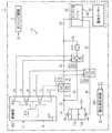
図2は、本発明の一実施例による駆動回路10を備える電気自動車1の機能的構成を示したブロック図である。 FIG. 2 is a block diagram illustrating a functional configuration of the
図2を参照すれば、電気自動車1は、センシング装置2、バッテリーパック100、駆動回路10、負荷20、電圧出力ライン11〜16及び電気ライン31〜38を含むことができる。 Referring to FIG. 2, the
また、駆動回路10は、第1コンタクタ210、第2コンタクタ220、第3コンタクタ230、電流制限回路240、電圧測定回路300及び制御部400を含むことができる。具現例によって、第1コンタクタ210、第2コンタクタ220及び第3コンタクタ230のうち少なくとも1つは、駆動回路10ではなく、電気自動車1に備えられても良い。 In addition, the driving
バッテリーパック100は、負荷20を動作させるため、所定範囲の動作電圧VHを出力するように構成される。図示されたように、バッテリーパック100は、相互電気的に直列で連結された複数のバッテリーモジュール110、120を含むことができる。このとき、バッテリーモジュール110、120のそれぞれは、少なくとも1つの単位セルを含むように構成され得る。The
負荷20は、インバータ21及び電気モーター22を含むことができる。キャパシタ21aに対するプリチャージが完了した後、接続部212、232が同時に閉動作位置(closed operational position)にある間、インバータ21の第1端子及び第2端子はそれぞれバッテリーパック100の第1端子130と第2端子140との間に電気的に連結される。これによって、インバータ21は電気ライン38を通じて電気モーター22に所定範囲の作動電圧を供給することができる。例えば、インバータ21は、バッテリーパック100から供給される直流電圧を交流電圧に変換した後、電気モーター22に供給することができる。キャパシタ21aに対するプリチャージ動作については後述する。 The
センシング装置2は、それぞれ異なるパラメーターを測定または演算する複数のセンサーを含む。また、センシング装置2は、それに含まれたセンサーによって収集される測定値を示す信号S1を制御部400に伝送することができる。 The
望ましくは、センシング装置2は、速度センサー、位置センサー及び傾きセンサーのうち少なくとも1つを含むことができる。速度センサーは、電気自動車1の走行速度を測定し、測定された走行速度を示す信号を制御部400に提供することができる。位置センサーは、電気自動車1の地理的位置に対応する信号を制御部400に提供することができる。例えば、位置センサーはGPS受信機で構成され得る。傾きセンサーは、電気自動車1の車体の傾きを示す信号を制御部400に提供することができる。センシング装置2から制御部400に提供される情報を「走行情報」と称し得る。 Desirably, the
すなわち、走行情報には電気自動車1の走行速度、地理的位置または車体の傾きに対する情報が含まれ、このような走行情報を示す信号S1が制御部400によって受信され、駆動回路10の制御に活用され得る。 That is, the travel information includes information on the travel speed, geographical position, or vehicle body tilt of the
制御部400は、駆動回路10の全般的な動作を制御する。特に、制御部400は、第1コンタクタ210、第2コンタクタ220及び第3コンタクタ230のうち少なくとも1つの動作位置を制御するように構成される。このような制御部400は、マイクロプロセッサ410、メモリ420及び少なくとも3つの電圧出力部431〜433を含むことができる。 The control unit 400 controls the overall operation of the
マイクロプロセッサ410は、ハードウェア的にASICs(Application Specific Integrated Circuits)、DSPs(Digital Signal Processors)、DSPDs(Digital Signal Processing Devices)、PLDs(Programmable Logic Devices)、FPGAs(Field Programmable Gate Arrays)、プロセッサ、マイクロコントローラ、その他の機能を果たすための電気的ユニットのうち少なくとも1つを用いて具現され得る。 The
具現例によって、マイクロプロセッサ410は電圧測定回路300の動作を制御することもできる。図4のように、電流制限回路240にスイッチング素子が含まれる場合、マイクロプロセッサ410は電流制限回路240に含まれたスイッチング素子それぞれの動作を個別的に制御し得る。 The
メモリ420は、駆動回路10の全般的な動作に必要な各種のデータ及び命令語を記憶することができる。マイクロプロセッサ410はメモリ420に記憶されたデータ及び命令語を参照して、第1コンタクタ210、第2コンタクタ220及び第3コンタクタ230の動作位置を制御するための信号を出力するか、または、第1コンタクタ210、第2コンタクタ220及び第3コンタクタ230の正常動作如何を判断するためのプロセスを実行することができる。 The
例えば、メモリは、フラッシュメモリ型、ハードディスク型、SSD(Solid State Disk)型、SDD(Silicon Disk Drive)型、MMCマイクロ(Multi−Media Card micro)型、RAM(Random Access Memory)、SRAM(Static RAM)、ROM(Read Only Memory)、EEPROM(Electrically Erasable Programmable ROM)、PROM(Programmable ROM)のうち少なくとも1つの形態の記憶媒体を含むことができる。 For example, the memory includes a flash memory type, a hard disk type, an SSD (Solid State Disk) type, an SDD (Silicon Disk Drive) type, an MMC micro (Multi-Media Card micro) type, a RAM (Random Access Memory), and an SRAM (Static RAM). ), ROM (Read Only Memory), EEPROM (Electrically Erasable Programmable ROM), and PROM (Programmable ROM).
第1電圧出力部431は、マイクロプロセッサ410から提供される信号に応じて、第1電圧出力ライン11及び第2電圧出力ライン12に所定レベルの電圧を出力することができる。例えば、第1電圧出力部431は、第1電圧出力ライン11に第1レベルの電圧を出力し、第2電圧出力ライン12に第2レベルの電圧を出力し得る。 The first
第2電圧出力部432は、マイクロプロセッサ410から提供される信号に応じて、第3電圧出力ライン13及び第4電圧出力ライン14に所定レベルの電圧を出力することができる。例えば、第2電圧出力部432は、第3電圧出力ライン13に第3レベルの電圧を出力し、第4電圧出力ライン14に第4レベルの電圧を出力し得る。 The second voltage output unit 432 can output a predetermined level of voltage to the third
第3電圧出力部433は、マイクロプロセッサ410から提供される信号に応じて、第5電圧出力ライン15及び第6電圧出力ライン16に所定レベルの電圧を出力することができる。例えば、第3電圧出力部433は、第5電圧出力ライン15に第5レベルの電圧を出力し、第6電圧出力ライン16に第6レベルの電圧を出力し得る。 The third
第1コンタクタ210は、第1コンタクタコイル211及び第1接続部212を含むことができる。このような第1コンタクタ210は、バッテリーパック100及び負荷20と電気的に直列で連結され得る。 The first contactor 210 may include a first contactor coil 211 and a
具体的に、第1コンタクタ210は、バッテリーパック100の第1端子130とキャパシタ21aの第1端子との間に直列で連結され得る。このとき、バッテリーパック100の第1端子130は、バッテリーパック100の両端子130、140のうち相対的に高い電位を有する端子130であり得る。 Specifically, the first contactor 210 may be connected in series between the
バッテリーパック100の第1端子130は電気ライン31を通じて第1接続部212の一端に連結され得る。また、第1接続部212の他端は電気ライン32を通じてキャパシタ21aの第1端子に電気的に連結され得る。 The
第1コンタクタコイル211の一端は第1電圧出力ライン11と電気的に連結され、第1コンタクタコイル211の他端は第2電圧出力ライン12と電気的に連結され得る。 One end of the first contactor coil 211 may be electrically connected to the first
制御部400は、第1コンタクタ210をターンオンさせるための制1制御信号を出力することができる。すなわち、第1制御信号は第1コンタクタ210のターンオンを誘導するものである。第1制御信号は第1電圧出力ライン11及び第2電圧出力ライン12を通じて第1コンタクタコイル211に提供され得る。具体的に、制御部400は第1電圧出力ライン11及び第2電圧出力ライン12のそれぞれに所定レベルの電圧を出力し、第1コンタクタコイル211に電源を印加し得る。このとき、第1電圧出力ライン11を通じて第1コンタクタコイル211の一端に出力される電圧のレベルは、第2電圧出力ライン12を通じて第1コンタクタコイル211の他端に出力される電圧のレベルとは相異なり得る。電源が印加された第1コンタクタコイル211に流れる電流によって第1接続部212は閉動作位置になる。第1接続部212が閉動作位置にある間、バッテリーパック100と負荷20とが電気的に連結され得る。 The controller 400 may output a
制御部400は、第1電圧出力ライン11及び第2電圧出力ライン12の少なくとも1つへの電圧の出力を中断して、第1コンタクタコイル211の電源を遮断することができる。第1コンタクタコイル211の電源が遮断される場合、第1接続部212は開動作位置(open operational position)になる。第1接続部212が開動作位置にある間、バッテリーパック100と負荷20とが電気的に分離され得る。 The controller 400 can interrupt the output of the voltage to at least one of the first
一方、第1コンタクタ210は「メインコンタクタ」とも称し得る。 On the other hand, the first contactor 210 may also be referred to as a “main contactor”.
第2コンタクタ220は、第2コンタクタコイル221及び第2接続部222を含むことができる。このような第2コンタクタ220は、それと直列で連結される電流制限回路240とともに、第1コンタクタ210に電気的に並列で連結され得る。 The
具体的に、第2接続部222の一端は電気ライン34を通じて電気ライン31に電気的に連結され得る。また、第2接続部222の他端は電流制限回路240及び電気ライン35を通じて電気ライン32に電気的に連結され得る。電流制限回路240に含まれるそれぞれの抵抗は「プリチャージ抵抗」と称し得る。例えば、電流制限回路240に2つの抵抗が含まれる場合、一方を第1プリチャージ抵抗と称し、他方を第2プリチャージ抵抗と称し得る。 Specifically, one end of the
第2コンタクタコイル221の一端は第3電圧出力ライン13と電気的に連結され、第2コンタクタコイル221の他端は第4電圧出力ライン14と電気的に連結され得る。 One end of the
制御部400は、第2コンタクタ220をターンオンさせるための制2制御信号を出力することができる。すなわち、第2制御信号は第2コンタクタ220のターンオンを誘導するものである。第2制御信号は第3電圧出力ライン13及び第4電圧出力ライン14を通じて第2コンタクタコイル221に提供され得る。具体的に、制御部400は第3電圧出力ライン13及び第4電圧出力ライン14のそれぞれに所定レベルの電圧を出力し、第2コンタクタコイル221に電源を印加し得る。このとき、第3電圧出力ライン13を通じて第2コンタクタコイル221の一端に出力される電圧のレベルは、第4電圧出力ライン14を通じて第2コンタクタコイル221の他端に出力される電圧のレベルとは相異なり得る。電源が印加された第2コンタクタコイル221に流れる電流によって第2接続部222は閉動作位置になる。第2接続部222が閉動作位置にある間、バッテリーパック100と負荷20とが電気的に連結され得る。 The controller 400 can output a
制御部400は、第3電圧出力ライン13及び第4電圧出力ライン14の少なくとも1つへの電圧の出力を中断して、第2コンタクタコイル221の電源を遮断することができる。第2コンタクタコイル221の電源が遮断される場合、第2コンタクタコイル221に電流が流れず、第2接続部222は開動作位置になる。第2接続部222が開動作位置にある間、バッテリーパック100と負荷20とが電気的に分離され得る。 The controller 400 can interrupt the output of the voltage to at least one of the third
一方、第2コンタクタ220は「プリチャージコンタクタ」とも称し得る。 On the other hand, the
第3コンタクタ230は、第3コンタクタコイル231及び第3接続部232を含むことができる。このような第3コンタクタ230はバッテリーパック100及び負荷20と電気的に直列で連結され得る。具体的に、第3接続部232の一端は電気ライン36を通じてバッテリーパック100の第2端子140に電気的に連結され得る。また、第3接続部232の他端は電気ライン37を通じてキャパシタ21aの第2端子に電気的に連結され得る。 The
第3コンタクタコイル231の一端は第5電圧出力ライン15と電気的に連結され、第3コンタクタコイル231の他端は第6電圧出力ライン16と電気的に連結され得る。 One end of the
制御部400は、第3コンタクタ230をターンオンさせるための第3制御信号を出力することができる。すなわち、第3制御信号は第3コンタクタ230のターンオンを誘導するものである。第3制御信号は第5電圧出力ライン15及び第6電圧出力ライン16を通じて第3コンタクタコイル231に提供され得る。具体的に、制御部400は第5電圧出力ライン15及び第6電圧出力ライン16のそれぞれに所定レベルの電圧を出力し、第3コンタクタコイル231に電源を印加し得る。このとき、第5電圧出力ライン15を通じて第3コンタクタコイル231の一端に出力される電圧のレベルは、第6電圧出力ライン16を通じて第3コンタクタコイル231の他端に出力される電圧のレベルとは相異なり得る。電源が印加された第3コンタクタコイル231に流れる電流によって第3接続部232は閉動作位置になる。第3接続部232が閉動作位置にある間、バッテリーパック100の第2端子とキャパシタ21aの第2端子とが電気的に連結され得る。 The controller 400 can output a third control signal for turning on the
制御部400は、第5電圧出力ライン15及び第6電圧出力ライン16の少なくとも1つへの電圧の出力を中断して、第3コンタクタコイル231の電源を遮断することができる。第3コンタクタコイル231の電源が遮断される場合、第3コンタクタコイル231に電流が流れず、第3接続部232は開動作位置になる。第3接続部232が開動作位置にある間、バッテリーパック100の第2端子とキャパシタ21aの第2端子とが電気的に分離され得る。 The controller 400 can interrupt the output of the voltage to at least one of the fifth
一方、第3コンタクタ230は「接地コンタクタ」とも称し得る。 On the other hand, the
駆動回路10は、第1接続部212が開動作位置であって、第2接続部222及び第3接続部232が閉動作位置にある間に、電流制限回路240を用いてバッテリーパック100から供給される電力をキャパシタ21aに供給することができる。これによって、第1接続部212が閉動作位置になる前に、キャパシタ21aをプリチャージすることができる。 The
制御部400は、キャパシタ21aが目標値以上にプリチャージされた後、第1接続部212を閉動作位置に誘導することで、高電圧を有するバッテリーパック100がキャパシタ21aに電気的に連結されるときの瞬間的な突入電流(inrush current)の大きさを減少させることができる。 After the
後述するように、駆動回路10は、第2コンタクタ220及び電流制限回路240を用いて、第1コンタクタ210の正常動作が可能な状態ではインバータ21に含まれたキャパシタ21aをプリチャージする基本的な動作をする上で、第1コンタクタ210が閉動作位置でない非正常な状態ではバッテリーパック100からキャパシタ21aへの電源供給のための電気的な連結を維持することを長所とする。 As will be described later, the
一方、第1コンタクタ210が非正常に動作する原因は多様である。例えば、第1コンタクタ210の第1コンタクタコイル211または第1接続部212が損傷された場合、制御部400から第1制御信号が出力されても、第1接続部212は閉動作位置になれない。また、第1コンタクタコイル211及び第1接続部212の損傷がなくても、第1電圧出力ライン11または第2電圧出力ライン12が断線するか又は第1電圧出力部431が故障した場合にも第1接続部212は閉動作位置になれない。 On the other hand, there are various reasons why the first contactor 210 operates abnormally. For example, when the first contactor coil 211 or the
電圧測定回路300は、第1電圧V1及び第2電圧V2をそれぞれ測定するように構成することができる。具体的に、第1電圧V1は電気ライン31の電位と基準点の電位との差を示し、第2電圧V2は電気ライン32の電位と前記基準点の電位との差を示し得る。換言すれば、第1電圧V1は第1コンタクタ210の両端のうちバッテリーパック100の第1端子130側に連結された一端の電圧を示し、第2電圧V2は第1コンタクタ210の両端のうちキャパシタ21a側に連結された他端の電圧を示し得る。この場合、基準点は接地またはバッテリーパック100の第2端子140であり得る。 The
電圧測定回路300は、第1及び第2電圧V1、V2に基づいて第1接続部212の両端に印加された電圧を測定することができる。例えば、第1コンタクタ210の両端に印加された電圧は、第1電圧V1と第2電圧V2との差であるV1−V2と同一であり得る。 The
電圧測定回路300は、第1接続部212の両端に印加された電圧を示す信号S2を制御部400に提供することができる。望ましくは、前記信号S2は二進数形式であって、所定週期毎に繰り返して出力される。 The
制御部400は、所定の条件が満たされた場合、電圧測定回路300を用いて第1接続部212の両端に印加された電圧を測定することができる。望ましくは、制御部400は第1制御信号を出力する間の少なくとも一時点で、電圧測定回路300を用いて第1接続部212の両端に印加された電圧を測定することができる。 The control unit 400 can measure the voltage applied to both ends of the
上述したように、第1制御信号は第1コンタクタ210のターンオンを誘導する信号である。すなわち、第1制御信号は、第1電圧出力ライン11及び第2電圧出力ライン12のそれぞれから出力される所定レベルの電圧に対応するものであり得る。例えば、電気自動車1の運転者がアクセルペダルを踏む場合、制御部400は第1制御信号を出力することができる。 As described above, the first control signal is a signal that induces turn-on of the first contactor 210. That is, the first control signal may correspond to a predetermined level of voltage output from each of the first
第1コンタクタ210が正常に動作可能な状態である場合、前記第1制御信号に応じて第1コンタクタコイル211に電源が印加されることで、第1接続部212は閉動作位置になるはずである。一方、第1コンタクタ210が故障などによって正常な動作が不可能な状態である場合、第1接続部212は第1制御信号が出力されているにもかかわらず、開動作位置になるはずである。 When the first contactor 210 is in a normally operable state, power is applied to the first contactor coil 211 in accordance with the first control signal, so that the
制御部400は、第1制御信号を出力する間、電圧測定回路300によって測定される第1コンタクタ210の両端の電圧に基づいて、第1コンタクタ210の正常動作如何を判断することができる。具現例によって、制御部400は、第1制御信号を出力する間に測定される第1接続部212の両端の電圧が所定の基準電圧以上である場合、第1コンタクタ210が非正常に動作していると判断することができる。 The controller 400 can determine whether the first contactor 210 is operating normally based on the voltage across the first contactor 210 measured by the
制御部400は、第1コンタクタ210が非正常に動作していると判断したとき、第1制御信号の出力を中断することができる。また、制御部400は、電気自動車1に備えられたモニタやスピーカなどを通じて、第1コンタクタ210が非正常に動作していることをユーザに通知するための信号を出力することもできる。 When the controller 400 determines that the first contactor 210 is operating abnormally, the controller 400 can interrupt the output of the first control signal. The control unit 400 can also output a signal for notifying the user that the first contactor 210 is operating abnormally through a monitor, a speaker, or the like provided in the
一方、制御部400は、第1制御信号が出力される間に測定される第1接続部212の両端の電圧が前記基準電圧未満である場合、第1コンタクタ210が正常に動作していると判断することができる。前記基準電圧は事前実験を通じて決定されるものであって、前記基準電圧を示すデータはメモリ420に予め記憶され得る。 On the other hand, when the voltage at both ends of the
図3は、本発明の一実施例による電流制限回路240の構成を示した概略図である。説明の便宜上、図2に示された第3接続部232は閉動作位置にあると仮定する。 FIG. 3 is a schematic diagram showing the configuration of the current limiting
図3を参照すれば、電流制限回路240は抵抗RPで構成され得る。具体的に、図示されたように、抵抗RPの一端は第2コンタクタ220及び電気ライン34を通じてバッテリーパック100の第1端子130に電気的に連結され得る。また、抵抗RPの他端は電気ライン35を通じてキャパシタ21aの第1端子に電気的に連結され得る。Referring to FIG. 3, the current limiting
望ましくは、制御部400は、第1コンタクタ210が非正常に動作していると判断される間、第2制御信号及び第3制御信号を出力することができる。 Preferably, the control unit 400 can output the second control signal and the third control signal while the first contactor 210 is determined to be operating abnormally.
第2制御信号によって第2接続部222は閉動作位置になり、第3制御信号によって第3接続部232は閉動作位置になる。これによって、第1コンタクタ210の故障などによって第1接続部212が開動作位置にある間(すなわち、閉動作位置になれない間)、キャパシタ21aの第1端子と第2端子はそれぞれ第2接続部222と第3接続部232を通じてバッテリーパック100の第1端子130と第2端子140に電気的に連結され得る。換言すれば、第1コンタクタ210が非正常に動作している間に、バッテリーパック100から供給される電力は第1コンタクタ210の代わりに第2コンタクタ220、抵抗RP及びインバータ21を通じて電気モーター22に供給され得る。結果的に、電気自動車1の非常走行が可能になる。The
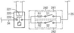
図4は、本発明の他の実施例による電流制限回路240の構成を示した概略図である。 FIG. 4 is a schematic diagram illustrating a configuration of a current limiting
電流制限回路240は複数の電流制限部を含むことができる。以下、説明の便宜上、電流制限回路240は2つの電流制限部241、242を含むと仮定する。電流制限回路240に含まれる一方の電流制限部は他方の電流制限部と電気的に並列で連結され得る。 The current limiting
第1電流制限部241は第1スイッチS1及び第1抵抗R1を含む。このとき、第1スイッチS1と第1抵抗R1とは相互直列で連結される。また、第2電流制限部242は、第1電流制限部241と同様に第2スイッチS2及び第2抵抗R2を含む。第2スイッチS2と第2抵抗R2とは相互直列で連結される。この場合、第1スイッチS1及び第2スイッチS2はMOFETのような公知のスイッチング素子であり得る。望ましくは、第1抵抗R1の抵抗値と第2抵抗R2の抵抗値とは相異なり得る。以下、第1抵抗R1の抵抗値が第2抵抗R2の抵抗値より大きいと仮定する。 The first current limiting
制御部400は、第1コンタクタ210が非正常動作中であって、且つ、第2制御信号が出力されている間に、第1スイッチS1及び第2スイッチS2の少なくとも1つをターンオンさせるための制御信号を出力することができる。具体的に、制御部400から第4制御信号が出力される場合、第1スイッチS1は第4制御信号によってターンオンされ得る。また、制御部400から第5制御信号が出力される場合、第2スイッチS2は第5制御信号によってターンオンされ得る。 The control unit 400 is configured to turn on at least one of the first switch S1 and the second switch S2 while the first contactor 210 is operating abnormally and the second control signal is being output. A control signal can be output. Specifically, when the fourth control signal is output from the controller 400, the first switch S1 may be turned on by the fourth control signal. When the fifth control signal is output from the controller 400, the second switch S2 can be turned on by the fifth control signal.
第4制御信号と第5制御信号とは同時に出力され得る。または、第4制御信号及び第5制御信号のいずれか1つ(例えば、第4制御信号)が出力されている間に、他の制御信号(例えば、第5制御信号)の出力は中断され得る。第4制御信号と第5制御信号とが同時に出力される場合、第1スイッチS1及び第2スイッチS2がターンオンされるため、第1抵抗R1と第2抵抗R2とは電気的に並列で連結される。第1抵抗R1と第2抵抗R2とが並列連結される場合、第1抵抗R1と第2抵抗R2とは1つの等価抵抗で表され得る。例えば、第1抵抗R1が3Ωであって、第2抵抗R2が1.5Ωである場合、第1抵抗R1と第2抵抗R2との並列連結による等価抵抗は1Ωであり得る。結果的に、他の条件(例えば、温度)が同一であると仮定するとき、第4制御信号及び第5制御信号のいずれか1つのみが出力される場合に比べて、第4制御信号と第5制御信号とが同時に出力される場合、電流制限回路240を通じて流れる電流が相対的に増加することができる。 The fourth control signal and the fifth control signal can be output simultaneously. Alternatively, while any one of the fourth control signal and the fifth control signal (for example, the fourth control signal) is being output, the output of the other control signal (for example, the fifth control signal) may be interrupted. . When the fourth control signal and the fifth control signal are output simultaneously, the first switch S1 and the second switch S2 are turned on, so that the first resistor R1 and the second resistor R2 are electrically connected in parallel. The When the first resistor R1 and the second resistor R2 are connected in parallel, the first resistor R1 and the second resistor R2 may be represented by one equivalent resistor. For example, when the first resistor R1 is 3Ω and the second resistor R2 is 1.5Ω, the equivalent resistance due to the parallel connection of the first resistor R1 and the second resistor R2 may be 1Ω. As a result, when it is assumed that other conditions (for example, temperature) are the same, the fourth control signal and the fourth control signal are compared with the case where only one of the fourth control signal and the fifth control signal is output. When the fifth control signal is output at the same time, the current flowing through the current limiting
一方、第1接続部212が開動作位置にあって、第2接続部222が閉動作位置にある間に、バッテリーパック100の第1端子130とキャパシタ21aの第1端子との間の電気的連結が第1抵抗R1と第2抵抗R2の何れを通じてなされるかによって、バッテリーパック100とキャパシタ21aとの間に流れる電流の大きさが変わり得る。したがって、制御部400は、電気自動車1のセンシング装置2から提供される走行情報に基づいて、第4制御信号と第5制御信号の何れを出力するかを決定することができる。 On the other hand, the electrical connection between the
一具現例によれば、第1コンタクタ210が非正常に動作していると判断される間の少なくとも一時点で電気自動車1の走行速度が基準速度(例えば、10km/h)未満である場合、制御部400は第2制御信号とともに第4制御信号を出力することができる。第2制御信号によって第2接続部222が閉動作位置になり、第4制御信号によって第1スイッチS1がターンオンされるため、バッテリーパック100の高電位端子である第1端子130が第2コンタクタ220、第1スイッチS1及び第1抵抗R1を通じてキャパシタ21aの第1端子に電気的に連結される。一方、第1コンタクタ210が非正常に動作していると判断される一時点で電気自動車1の走行速度が前記基準速度以上である場合、制御部400は第2制御信号とともに第5制御信号を出力することができる。第2制御信号によって第2接続部222が閉動作位置になり、第5制御信号によって第2スイッチS2がターンオンされるため、バッテリーパック100の高電位端子である第1端子130が第2コンタクタ220、第2スイッチS2及び第2抵抗R2を通じてキャパシタ21aの第1端子に電気的に連結される。 According to an embodiment, when the traveling speed of the
電気自動車1の走行速度が基準速度未満であるということは、走行速度が基準速度以上であるときより前記電気モーター22が必要とする電力が相対的に低いことを意味する。この場合、バッテリーパック100からの電力は第1抵抗R1を通じてインバータ21に供給されるため、バッテリーパック100からの電力が第2抵抗R2を通じてインバータ21に供給される場合より、バッテリーパック100とキャパシタ21aとの間に流れる電流の大きさが小さくなる。 That the traveling speed of the
他の具現例によれば、第1コンタクタ210が非正常に動作していると判断される間の少なくとも一時点における電気自動車1の地理的位置に基づいて、第4制御信号と第5制御信号の何れを出力するかを決定することができる。例えば、制御部400は、電気自動車1の現在の地理的位置から最寄りの整備所までの距離が基準距離(例えば、40km)未満である場合、第2制御信号とともに第4制御信号を出力することができる。一方、制御部400は、電気自動車1から最寄りの整備所までの距離が基準距離以上である場合、第2制御信号とともに第5制御信号を出力することができる。 According to another embodiment, the fourth control signal and the fifth control signal are based on the geographical position of the
換言すれば、電気自動車1から最寄りの整備所までの距離が相対的に近いほど、電気モーター22が必要とする電力は減少するため、第1抵抗R1及び第2抵抗R2のうち相対的に抵抗値が大きい第1抵抗R1を通じてバッテリーパック100とキャパシタ21aとを電気的に連結する。逆に、電気自動車1から最寄りの整備所までの距離が相対的に遠いほど、電気モーター22が必要とする電力は増加するため、第1抵抗R1及び第2抵抗R2のうち相対的に抵抗値が小さい第2抵抗R2を通じてバッテリーパック100とキャパシタ21aとを電気的に連結する。 In other words, since the electric power required by the
一方、上述した電気自動車1の現在の地理的位置から最寄りの整備所までの距離を示すデータは、制御部400によって演算されるか、または、電気自動車1のセンシング装置2やMCUなどから提供されるものであり得る。 On the other hand, the data indicating the distance from the current geographical position of the
また、他の具現例によれば、第1コンタクタ210が非正常に動作していると判断される一時点において、電気自動車1の車体の傾きが基準角度未満である場合、制御部400は第2制御信号とともに第4制御信号を出力することができる。この場合、第1制御信号及び第5制御信号の出力は中断され得る。 Further, according to another embodiment, when the tilt of the vehicle body of the
一方、第1コンタクタ210が非正常に動作していると判断される一時点において、電気自動車1の車体の傾きが前記基準角度以上である場合、制御部400は第2制御信号とともに第5制御信号を出力することができる。この場合、第1制御信号及び第4制御信号の出力は中断され得る。 On the other hand, when the inclination of the vehicle body of the
電気自動車1の車体の傾きが基準角度未満であるということは、電気自動車1が平地のような傾斜の緩い道路を走行中であることを意味する。すなわち、電気自動車1が傾斜の緩い道路を走行している場合、急傾斜の道路を走行する場合より電気モーター22が必要とする電力が相対的に低くなり得る。この場合、バッテリーパック100からの電力は第1抵抗R1を通じてインバータ21に供給されるため、バッテリーパック100からの電力が第2抵抗R2を通じてインバータ21に供給される場合より、バッテリーパック100とキャパシタ21aとの間に流れる電流の大きさは小さくなる。 That the inclination of the body of the
図5は、本発明の一実施例による駆動回路10の制御方法を示したフロー図である。説明の便宜上、制御部400は第3制御信号を出力している状態、すなわち、第3接続部232が閉動作位置にあると仮定する。 FIG. 5 is a flowchart illustrating a method for controlling the driving
段階S510において、制御部400は第1制御信号を出力する。第1制御信号は第1コンタクタ210のターンオンを誘導する信号である。一例において、第1制御信号は運転者の命令(例えば、アクセルペダルを踏む)によって出力されるものであり得る。具体的に、制御部400は、第1電圧出力部431を用いて、第1電圧出力ライン11を通じて第1レベルの電圧を出力し、第2電圧出力ライン12を通じて第2レベルの電圧を出力することができる。 In step S510, the controller 400 outputs a first control signal. The first control signal is a signal that induces turn-on of the first contactor 210. In one example, the first control signal may be output by a driver's command (for example, depressing an accelerator pedal). Specifically, the control unit 400 outputs a first level voltage through the first
段階S520において、制御部400は、段階S510において第1制御信号を出力する間、第1コンタクタ210が正常動作中であるか否かを判断する。 In step S520, the controller 400 determines whether or not the first contactor 210 is operating normally while outputting the first control signal in step S510.
具体的に、第1コンタクタ210が正常に動作していれば、第1制御信号によって第1接続部212は閉動作位置になり、電圧測定回路300によって測定される第1コンタクタ210の両端の電圧は基準電圧未満のはずである。 Specifically, if the first contactor 210 is operating normally, the
制御部400は、第1制御信号の出力中に測定される第1コンタクタ210の両端の電圧が基準電圧より小さい場合、第1コンタクタ210が正常に動作可能であると判断することができる。もし、第1制御信号の出力中に測定される第1コンタクタ210の両端の電圧が基準電圧以上である場合、制御部400は、第1コンタクタ210が非正常に動作していると判断することができる。 The controller 400 may determine that the first contactor 210 can operate normally when the voltage across the first contactor 210 measured during the output of the first control signal is smaller than the reference voltage. If the voltage across the first contactor 210 measured during the output of the first control signal is equal to or higher than the reference voltage, the controller 400 determines that the first contactor 210 is operating abnormally. Can do.
段階S520の判断値が「はい」である場合、制御部400は段階S510に戻る。一方、段階S520の判断値が「いいえ」である場合、制御部400は段階S530に進む。 If the determination value in step S520 is “Yes”, the controller 400 returns to step S510. On the other hand, if the determination value in step S520 is “No”, the controller 400 proceeds to step S530.
段階S530において、制御部400は第2制御信号を出力する。第2制御信号は第2コンタクタ220のターンオンを誘導する信号である。具体的に、制御部400は、第2電圧出力部432を用いて、第3電圧出力ライン13を通じて第3レベルの電圧を出力し、第4電圧出力ライン14を通じて第4レベルの電圧を出力することができる。 In step S530, the controller 400 outputs a second control signal. The second control signal is a signal that induces turn-on of the
第2コンタクタ220が第2制御信号によってターンオンされ、バッテリーパック100と負荷20とを電気的に連結することができる。具体的に、第2制御信号によって第2接続部222が閉動作位置になることで、バッテリーパック100の第1端子130は、第2コンタクタ220と電流制限回路240を通じてキャパシタ21aの第1端子に電気的に連結可能な状態になり得る。 The
具現例によって、図4を参照して上述したように、電流制限回路240は相互並列で連結される第1電流制限部241及び第2電流制限部242をさらに含むことができる。この場合、前記制御方法は段階S540及びS550をさらに含むことができる。 As described above with reference to FIG. 4, the
段階S540において、制御部400は電気自動車1の走行情報に基づいて、電流制限回路240に含まれた少なくとも1つのスイッチを選択することができる。例えば、制御部400は第1スイッチS1と第2スイッチS2のいずれか1つのみを選択するか、または、2つのスイッチS1、S2を全て選択することができる。走行情報は、電気自動車1の走行速度、地理的位置または車体の傾きに関する情報を示すものであり得る。 In step S540, the control unit 400 can select at least one switch included in the current limiting
段階S550において、制御部400は段階S540で選択されたスイッチをターンオンさせることができる。例えば、制御部400は、第1スイッチS1が選択された場合は第4制御信号を出力し、第2スイッチS2が選択された場合は第5制御信号を出力することができる。 In step S550, the controller 400 may turn on the switch selected in step S540. For example, the control unit 400 can output a fourth control signal when the first switch S1 is selected, and can output a fifth control signal when the second switch S2 is selected.
第1スイッチS1は、第4制御信号によってターンオンされ得る。この場合、第1抵抗R1の抵抗値に対応するほど制限された電流がバッテリーパック100からインバータ21に供給され得る。第2スイッチS2は第5制御信号によってターンオンされ得る。この場合、第2抵抗R2の抵抗値に対応するほど制限された電流がバッテリーパック100からインバータ21に供給され得る。 The first switch S1 can be turned on by the fourth control signal. In this case, a current limited so as to correspond to the resistance value of the first resistor R <b> 1 can be supplied from the
これによって、バッテリーパック100から第2コンタクタ220と電流制限回路240を介してインバータ21に電力が供給され、インバータ21はバッテリーパック100から供給される電力を電気モーター22が必要とする電力に変換することができる。 As a result, electric power is supplied from the
上述した本発明の実施例は、装置及び方法のみを通じて具現されるものではなく、本発明の実施例の構成に対応する機能を実行するプログラム又はそのプログラムが記録された記録媒体を通じても具現でき、上述した実施例の記載から本発明が属する技術分野の当業者であれば容易に具現することができる。 The embodiments of the present invention described above are not embodied only through the apparatus and method, but can also be implemented through a program that executes a function corresponding to the configuration of the embodiments of the present invention or a recording medium on which the program is recorded. Those skilled in the art to which the present invention belongs can be easily implemented from the above description of the embodiments.
以上のように、本発明を限定された実施例と図面によって説明したが、本発明はこれに限定されるものではなく、本発明の属する技術分野で通常の知識を持つ者によって本発明の技術思想と特許請求の範囲の均等範囲内で多様な修正及び変形が可能であることは言うまでもない。 As described above, the present invention has been described with reference to the limited embodiments and drawings. It goes without saying that various modifications and variations can be made within the scope of the idea and the scope of claims.
また、上述した本発明は、本発明が属する技術分野で通常の知識を持つ者によって本発明の技術的思想から逸脱しない範囲内で様々な置換、変形及び変更が可能であるため、上述した実施例及び添付された図面によって限定されるものではなく、多様な変形のため各実施例の全部または一部を選択的に組み合わせて構成することができる。 In addition, since the present invention described above can be variously replaced, modified, and changed by a person having ordinary knowledge in the technical field to which the present invention belongs, without departing from the technical idea of the present invention, The present invention is not limited to the examples and the attached drawings, and may be configured by selectively combining all or a part of the embodiments for various modifications.
Claims (11)
Translated fromJapanese前記バッテリーパックの第1端子と前記インバータに含まれたキャパシタの第1端子との間に連結される第1コンタクタ;
前記第1コンタクタに並列連結される第2コンタクタ及び電流制限回路;並びに、
前記第1コンタクタ及び前記第2コンタクタの動作を制御する制御部;を含んでなり、
前記第2コンタクタと前記電流制限回路とは相互直列で連結され、
前記電流制限回路は少なくとも1つの抵抗を含んでなり、
前記制御部は、前記第1コンタクタの正常動作中には第1制御信号を出力し、前記第1コンタクタの非正常動作中には第2制御信号を出力し、
前記第1制御信号は前記第1コンタクタのターンオンを誘導し、
前記第2制御信号は前記第2コンタクタのターンオンを誘導し、
前記電流制限回路は、前記第2コンタクタと直列連結される第1電流制限部、及び前記第1電流制限部と並列連結される第2電流制限部を含んでなり、
前記第1電流制限部は相互直列で連結される第1スイッチ及び第1抵抗を含んでなり、
前記第2電流制限部は相互直列で連結される第2スイッチ及び第2抵抗を含んでなり、
前記制御部は、前記第1コンタクタの非正常動作中には前記第1スイッチ及び前記第2スイッチの少なくとも1つをターンオンさせ、
前記制御部は、前記電気自動車の走行情報に基づいて、前記第1スイッチ及び前記第2スイッチの少なくとも1つをターンオンさせる、電気自動車用駆動回路。A drive circuit for an electric vehicle including a battery pack and an inverter,
A first contactor connected between a first terminal of the battery pack and a first terminal of a capacitor included in the inverter;
A second contactor connected in parallel to the first contactor and a current limiting circuit; and
A control unit for controlling operations of the first contactor and the second contactor;
The second contactor and the current limiting circuit are connected in series with each other,
The current limiting circuit comprises at least one resistor;
The control unit outputs a first control signal during normal operation of the first contactor, and outputs a second control signal during abnormal operation of the first contactor;
The first control signal induces turn-on of the first contactor;
The second control signal induces turn-on of the second contactor;
The current limiting circuit includes a first current limiting unit connected in series with the second contactor, and a second current limiting unit connected in parallel with the first current limiting unit,
The first current limiting unit includes a first switch and a first resistor connected in series.
The second current limiting unit includes a second switch and a second resistor connected in series.
The control unit turns on at least one of the first switch and the second switch during an abnormal operation of the first contactor,
The control unit is a drive circuit foran electric vehiclethat turns on at least one of the first switch and the second switch based on travel information of the electric vehicle.
前記制御部は前記第1コンタクタの正常動作中には前記第2制御信号とともに第3制御信号を出力し、
前記第3制御信号は前記第3コンタクタのターンオンを誘導する、請求項1に記載の電気自動車用駆動回路。A third contactor connected between the second terminal of the battery pack and the second terminal of the capacitor;
The control unit outputs a third control signal together with the second control signal during normal operation of the first contactor,
The drive circuit for an electric vehicle according to claim 1, wherein the third control signal induces turn-on of the third contactor.
前記第1スイッチは、前記第4制御信号によってターンオンされる、請求項7に記載の電気自動車用駆動回路。When the resistance value of the first resistor is larger than the resistance value of the second resistor and the traveling speed is lower than a reference speed during the abnormal operation of the first contactor, the control unit, together with the second control signal Outputs a fourth control signal,
The drive circuit for an electric vehicle according to claim 7, wherein the first switch is turned on by the fourth control signal.
前記第2スイッチは、前記第5制御信号によってターンオンされる、請求項7又は8に記載の電気自動車用駆動回路。When the resistance value of the first resistor is larger than the resistance value of the second resistor and the traveling speed is equal to or higher than a reference speed during the abnormal operation of the first contactor, the control unit, together with the second control signal Outputs a fifth control signal;
The drive circuit for an electric vehicle according to claim 7 or 8, wherein the second switch is turned on by the fifth control signal.
前記制御部が第1制御信号を出力する段階;
前記制御部が前記第1制御信号を出力する間、前記第1コンタクタの正常動作如何を判断する段階;
前記第1コンタクタが非正常に動作していると判断される間、前記制御部が前記第2制御信号を出力する段階;及び
前記第2コンタクタが前記第2制御信号によってターンオンされて、前記バッテリーパックの第1端子と前記キャパシタの第1端子とを電気的に連結する段階;を含んでなる、電気自動車用駆動回路の制御方法。A method for controlling a drive circuit for an electric vehicle according to any one of claims 1 to 9,
The controller outputs a first control signal;
Determining whether the first contactor operates normally while the control unit outputs the first control signal;
The controller outputs the second control signal while it is determined that the first contactor is operating abnormally; and the second contactor is turned on by the second control signal, and the battery Electrically controlling the first terminal of the pack and the first terminal of the capacitor;
Applications Claiming Priority (3)
| Application Number | Priority Date | Filing Date | Title |
|---|---|---|---|
| KR1020160078193AKR102145524B1 (en) | 2016-06-22 | 2016-06-22 | Driver circuit for an electric vehicle and control method for the same |
| KR10-2016-0078193 | 2016-06-22 | ||
| PCT/KR2017/005064WO2017222186A1 (en) | 2016-06-22 | 2017-05-16 | Driving circuit for electric vehicle and control method therefor |
Publications (2)
| Publication Number | Publication Date |
|---|---|
| JP2018538774A JP2018538774A (en) | 2018-12-27 |
| JP6616902B2true JP6616902B2 (en) | 2019-12-04 |
Family
ID=60784516
Family Applications (1)
| Application Number | Title | Priority Date | Filing Date |
|---|---|---|---|
| JP2018529548AActiveJP6616902B2 (en) | 2016-06-22 | 2017-05-16 | Electric vehicle drive circuit and control method thereof |
Country Status (7)
| Country | Link |
|---|---|
| US (1) | US10807474B2 (en) |
| EP (1) | EP3354511B1 (en) |
| JP (1) | JP6616902B2 (en) |
| KR (1) | KR102145524B1 (en) |
| CN (1) | CN108349406B (en) |
| PL (1) | PL3354511T3 (en) |
| WO (1) | WO2017222186A1 (en) |
Families Citing this family (15)
| Publication number | Priority date | Publication date | Assignee | Title |
|---|---|---|---|---|
| WO2018179480A1 (en)* | 2017-03-30 | 2018-10-04 | パナソニックIpマネジメント株式会社 | Vehicle electricity storage device |
| JP7020952B2 (en)* | 2018-02-13 | 2022-02-16 | 本田技研工業株式会社 | Power system |
| WO2019170476A1 (en)* | 2018-03-08 | 2019-09-12 | Cpt Group Gmbh | Alternating-current charging device for a motor vehicle, and method for operating an alternating-current charging device for a motor vehicle, and motor vehicle |
| KR102423888B1 (en)* | 2018-08-13 | 2022-07-20 | 주식회사 엘지에너지솔루션 | Apparatus for controlling switch |
| KR102593366B1 (en)* | 2018-10-18 | 2023-10-23 | 주식회사 엘지에너지솔루션 | System and method for measuring multiple signal |
| KR102654842B1 (en)* | 2018-12-10 | 2024-04-05 | 현대자동차주식회사 | Battery system of vehicle and diagnostic method thereof |
| KR102770458B1 (en)* | 2019-12-16 | 2025-02-21 | 현대자동차주식회사 | System and method for controlling degradation of power relay assembly for vehicle |
| KR20210115479A (en)* | 2020-03-13 | 2021-09-27 | 엘지이노텍 주식회사 | Electric vehicle charging controller and apparatus for charging electric vehicle comprising the same |
| US12006015B2 (en) | 2020-05-13 | 2024-06-11 | Liquid Propulsion, Llc | Thrust system for steering marine vessels |
| CN111525656B (en)* | 2020-06-03 | 2022-03-18 | 桑顿新能源科技(长沙)有限公司 | Battery electric energy feedback system and vehicle |
| CN112078368B (en)* | 2020-08-03 | 2022-03-29 | 湖南中联重科智能高空作业机械有限公司 | Feedback current control device and overhead working truck |
| CA3166723A1 (en)* | 2020-09-27 | 2022-03-31 | Zoomlion Intelligent Access Machinery Co., Ltd. | Lithium battery system and overhead working truck |
| KR20230054153A (en)* | 2021-10-15 | 2023-04-24 | 주식회사 엘지에너지솔루션 | Battery managing apparatus and operating method of the same |
| CN114030373B (en)* | 2021-11-02 | 2024-05-14 | 深圳麦格米特电气股份有限公司 | Power supply processing circuit, vehicle-mounted charger and charging gun identification method |
| US20240413633A1 (en)* | 2023-06-06 | 2024-12-12 | Smartville, Inc. | Pre-Charge Voltage Balancer |
Family Cites Families (47)
| Publication number | Priority date | Publication date | Assignee | Title |
|---|---|---|---|---|
| JPH0669270B2 (en)* | 1989-08-10 | 1994-08-31 | いすゞ自動車株式会社 | Capacitor charging device |
| JP3191481B2 (en)* | 1993-04-21 | 2001-07-23 | 松下電器産業株式会社 | Automotive air conditioners |
| JP3555534B2 (en) | 2000-01-24 | 2004-08-18 | 株式会社デンソー | Battery cell voltage detector |
| JP3945630B2 (en)* | 2002-01-10 | 2007-07-18 | パナソニック・イーブイ・エナジー株式会社 | Relay contact welding inspection method for battery power supply |
| US6768621B2 (en)* | 2002-01-18 | 2004-07-27 | Solectria Corporation | Contactor feedback and precharge/discharge circuit |
| JP4543844B2 (en) | 2004-09-10 | 2010-09-15 | トヨタ自動車株式会社 | Power supply circuit control device |
| KR100694062B1 (en) | 2004-10-27 | 2007-03-12 | 삼성전자주식회사 | Multiple battery charger and control method |
| JP4466327B2 (en) | 2004-11-04 | 2010-05-26 | トヨタ自動車株式会社 | Vehicle power supply |
| JP4671336B2 (en) | 2005-05-09 | 2011-04-13 | 株式会社小松製作所 | Motor drive device |
| JP4804994B2 (en)* | 2006-04-05 | 2011-11-02 | 株式会社小松製作所 | Forklift power supply |
| KR100877854B1 (en) | 2007-03-27 | 2009-01-13 | 현대자동차주식회사 | Emergency Drive Method for Power Conversion Unit of Hybrid Vehicle |
| CN101073990B (en)* | 2007-06-22 | 2011-06-01 | 深圳先进技术研究院 | Electric vehicle power supply system with safety protection device and control method thereof |
| JP4288333B1 (en) | 2007-12-18 | 2009-07-01 | トヨタ自動車株式会社 | Vehicle power supply |
| KR101103616B1 (en)* | 2008-01-07 | 2012-01-09 | 에스케이이노베이션 주식회사 | Pre-Charge Protection Circuit Device Using Interlock Switch |
| JP4978476B2 (en)* | 2008-01-09 | 2012-07-18 | 株式会社デンソー | Power supply status detection device |
| KR101068583B1 (en) | 2009-01-09 | 2011-09-30 | 부산대학교 산학협력단 | Safety system and control method of hybrid vehicle |
| US8040139B2 (en) | 2009-02-16 | 2011-10-18 | Maxim Integrated Products, Inc. | Fault detection method for detecting leakage paths between power sources and chassis |
| JP5221468B2 (en)* | 2009-02-27 | 2013-06-26 | 株式会社日立製作所 | Battery monitoring device |
| JP5656415B2 (en)* | 2009-03-26 | 2015-01-21 | プライムアースEvエナジー株式会社 | Secondary battery state determination device and control device |
| WO2011028703A2 (en)* | 2009-09-01 | 2011-03-10 | Boston-Power, Inc. | Safety and performance optimized controls for large scale electric vehicle battery systems |
| US8550405B2 (en)* | 2009-09-29 | 2013-10-08 | Busek Company, Inc. | Solar powered spacecraft power system for a hall effect thruster |
| KR101079938B1 (en)* | 2009-10-13 | 2011-11-04 | 대성전기공업 주식회사 | A Driving Circuit for Solid State Switch of Automobile |
| KR101057547B1 (en)* | 2010-01-26 | 2011-08-17 | 에스비리모티브 주식회사 | Battery Management System and Its Driving Method |
| KR101057542B1 (en)* | 2010-01-26 | 2011-08-17 | 에스비리모티브 주식회사 | Battery Management System and Its Driving Method |
| JP5584927B2 (en)* | 2010-06-04 | 2014-09-10 | 日立オートモティブシステムズ株式会社 | Battery control device and power storage device |
| US8655535B2 (en)* | 2010-07-09 | 2014-02-18 | Lg Electronics Inc. | Electric vehicle and method for controlling same |
| US8288031B1 (en)* | 2011-03-28 | 2012-10-16 | Lg Chem, Ltd. | Battery disconnect unit and method of assembling the battery disconnect unit |
| KR101255248B1 (en)* | 2011-07-04 | 2013-04-16 | 로베르트 보쉬 게엠베하 | Battery management system and control method thereof |
| US9024468B2 (en) | 2012-07-02 | 2015-05-05 | Lg Chem, Ltd. | Driver circuit for an electric vehicle and a diagnostic method for determining when a voltage driver is shorted to a ground voltage |
| US9266433B2 (en)* | 2012-07-23 | 2016-02-23 | Ford Global Technologies, Llc | Low cost charger circuit with precharge |
| DE102012213057B4 (en)* | 2012-07-25 | 2020-10-29 | Robert Bosch Gmbh | Method for controlling a battery system, battery system and motor vehicle |
| KR20140070148A (en) | 2012-11-30 | 2014-06-10 | 에스케이이노베이션 주식회사 | Battery current detecting apparatus and method thereof |
| KR101470098B1 (en) | 2012-12-18 | 2014-12-05 | 현대자동차주식회사 | Fault diagnosis system and method for relay of vehicle |
| KR101563867B1 (en)* | 2013-02-06 | 2015-10-28 | 엘지전자 주식회사 | charging apparatus and electric vehicle including the same |
| WO2014134218A1 (en) | 2013-02-26 | 2014-09-04 | Zonit Structured Solutions, Llc | Parallel redundant power distribution |
| US10464507B2 (en)* | 2013-03-07 | 2019-11-05 | Samsung Sdi Co., Ltd. | Battery management system and switching method thereof |
| US9726725B2 (en)* | 2013-08-02 | 2017-08-08 | Jtekt Corporation | Power circuit abnormality detection method |
| JP6191315B2 (en) | 2013-08-02 | 2017-09-06 | 株式会社ジェイテクト | Abnormality detection method for power supply circuit |
| KR101717611B1 (en) | 2013-09-04 | 2017-03-17 | 한온시스템 주식회사 | Air conditioning system for automotive vehicles |
| US9925878B2 (en)* | 2013-09-26 | 2018-03-27 | Ford Global Technologies, Llc | Bus pre-charge control using a buck converter |
| US9209635B2 (en)* | 2013-12-02 | 2015-12-08 | Lg Chem, Ltd. | Pre-charging system for a capacitor in a voltage inverter for an electric motor |
| US9214888B2 (en)* | 2013-12-20 | 2015-12-15 | Lg Chem, Ltd. | Pre-charging system for a capacitor in a voltage inverter for an electric motor |
| KR101551035B1 (en)* | 2013-12-30 | 2015-09-08 | 현대자동차주식회사 | Method for diagnosing breakdown during pre-charging |
| JP5958477B2 (en) | 2014-01-22 | 2016-08-02 | 株式会社豊田自動織機 | Inverter device |
| US9413184B2 (en)* | 2014-03-21 | 2016-08-09 | Lg Chem, Ltd. | Pre-charging and voltage supply system for a DC-AC inverter |
| KR102302783B1 (en)* | 2014-07-25 | 2021-09-16 | 현대모비스 주식회사 | Vehicle Driving System and Method |
| JP6729390B2 (en)* | 2014-12-24 | 2020-07-22 | 株式会社Gsユアサ | Power protection device, power supply device and switch failure diagnosis method |
- 2016
- 2016-06-22KRKR1020160078193Apatent/KR102145524B1/enactiveActive
- 2017
- 2017-05-16JPJP2018529548Apatent/JP6616902B2/enactiveActive
- 2017-05-16EPEP17815599.0Apatent/EP3354511B1/enactiveActive
- 2017-05-16USUS15/765,626patent/US10807474B2/enactiveActive
- 2017-05-16PLPL17815599Tpatent/PL3354511T3/enunknown
- 2017-05-16CNCN201780003750.6Apatent/CN108349406B/enactiveActive
- 2017-05-16WOPCT/KR2017/005064patent/WO2017222186A1/ennot_activeCeased
Also Published As
| Publication number | Publication date |
|---|---|
| EP3354511B1 (en) | 2022-03-30 |
| CN108349406B (en) | 2021-03-30 |
| CN108349406A (en) | 2018-07-31 |
| WO2017222186A1 (en) | 2017-12-28 |
| PL3354511T3 (en) | 2022-06-13 |
| US10807474B2 (en) | 2020-10-20 |
| KR102145524B1 (en) | 2020-08-18 |
| JP2018538774A (en) | 2018-12-27 |
| KR20180000234A (en) | 2018-01-02 |
| US20190077267A1 (en) | 2019-03-14 |
| EP3354511A4 (en) | 2018-12-19 |
| EP3354511A1 (en) | 2018-08-01 |
Similar Documents
| Publication | Publication Date | Title |
|---|---|---|
| JP6616902B2 (en) | Electric vehicle drive circuit and control method thereof | |
| CN104662771B (en) | Charging control device and charging control method | |
| JP4513494B2 (en) | Control device and control method for voltage converter | |
| EP3672021B1 (en) | Apparatus for preventing over-discharge | |
| EP2413453A2 (en) | Power supply device having precharging circuit for charging capacitor | |
| AU2019265165A1 (en) | Battery control apparatus and energy storage system including same | |
| WO2011102543A1 (en) | Quick charging device and mobile charging apparatus | |
| KR101673822B1 (en) | Apparatus and method for detecting relay welding in green car | |
| EP2994989B1 (en) | Pre-charging and voltage supply system for a dc-ac inverter | |
| KR102347920B1 (en) | Apparatus and method for battery management | |
| US10124693B2 (en) | Battery pack and electric vehicle including the same | |
| JP2013516954A (en) | Battery control apparatus and method | |
| CN111886772A (en) | Balancing device, battery management system and battery pack including the same | |
| JPWO2013141196A1 (en) | Power supply device for vehicle and vehicle provided with this power supply device | |
| JP7331327B2 (en) | Battery management system, battery management method, battery pack and electric vehicle | |
| KR20170097481A (en) | Charging or discharging system and method for diagnosing state of contactor | |
| KR102364237B1 (en) | Apparatus and method for pre-charging | |
| KR20150054464A (en) | Charging method of battery and battery charging system | |
| KR20220021277A (en) | Battery management system, battery management method, battery pakc, and electric vehicle | |
| KR20160132691A (en) | Electric transfer means and the control method thereof | |
| CN113785464B (en) | Apparatus and method for controlling power of parallel multi-group system | |
| JP2008125159A (en) | Power supply | |
| KR102404816B1 (en) | Apparatus and method for diagnosing currentsensor | |
| KR102109925B1 (en) | Driver circuit for an electric vehicle and control method for the same | |
| KR20200076423A (en) | Appartus and method for diagnosing relay |
Legal Events
| Date | Code | Title | Description |
|---|---|---|---|
| A621 | Written request for application examination | Free format text:JAPANESE INTERMEDIATE CODE: A621 Effective date:20180607 | |
| A977 | Report on retrieval | Free format text:JAPANESE INTERMEDIATE CODE: A971007 Effective date:20190404 | |
| A131 | Notification of reasons for refusal | Free format text:JAPANESE INTERMEDIATE CODE: A131 Effective date:20190416 | |
| A521 | Request for written amendment filed | Free format text:JAPANESE INTERMEDIATE CODE: A523 Effective date:20190712 | |
| TRDD | Decision of grant or rejection written | ||
| A01 | Written decision to grant a patent or to grant a registration (utility model) | Free format text:JAPANESE INTERMEDIATE CODE: A01 Effective date:20191015 | |
| A61 | First payment of annual fees (during grant procedure) | Free format text:JAPANESE INTERMEDIATE CODE: A61 Effective date:20191108 | |
| R150 | Certificate of patent or registration of utility model | Ref document number:6616902 Country of ref document:JP Free format text:JAPANESE INTERMEDIATE CODE: R150 | |
| S111 | Request for change of ownership or part of ownership | Free format text:JAPANESE INTERMEDIATE CODE: R313111 | |
| R350 | Written notification of registration of transfer | Free format text:JAPANESE INTERMEDIATE CODE: R350 | |
| R250 | Receipt of annual fees | Free format text:JAPANESE INTERMEDIATE CODE: R250 | |
| R250 | Receipt of annual fees | Free format text:JAPANESE INTERMEDIATE CODE: R250 | |
| R250 | Receipt of annual fees | Free format text:JAPANESE INTERMEDIATE CODE: R250 |