JP6613407B2 - Code generator - Google Patents
Code generatorDownload PDFInfo
- Publication number
- JP6613407B2 JP6613407B2JP2019000364AJP2019000364AJP6613407B2JP 6613407 B2JP6613407 B2JP 6613407B2JP 2019000364 AJP2019000364 AJP 2019000364AJP 2019000364 AJP2019000364 AJP 2019000364AJP 6613407 B2JP6613407 B2JP 6613407B2
- Authority
- JP
- Japan
- Prior art keywords
- electrode
- code
- information
- touch panel
- information processing
- Prior art date
- Legal status (The legal status is an assumption and is not a legal conclusion. Google has not performed a legal analysis and makes no representation as to the accuracy of the status listed.)
- Expired - Fee Related
Links
Images


Classifications
- G—PHYSICS
- G06—COMPUTING OR CALCULATING; COUNTING
- G06K—GRAPHICAL DATA READING; PRESENTATION OF DATA; RECORD CARRIERS; HANDLING RECORD CARRIERS
- G06K7/00—Methods or arrangements for sensing record carriers, e.g. for reading patterns
- G06K7/10—Methods or arrangements for sensing record carriers, e.g. for reading patterns by electromagnetic radiation, e.g. optical sensing; by corpuscular radiation
- G06K7/14—Methods or arrangements for sensing record carriers, e.g. for reading patterns by electromagnetic radiation, e.g. optical sensing; by corpuscular radiation using light without selection of wavelength, e.g. sensing reflected white light
- G06K7/1404—Methods for optical code recognition
- G06K7/1408—Methods for optical code recognition the method being specifically adapted for the type of code
- G—PHYSICS
- G06—COMPUTING OR CALCULATING; COUNTING
- G06K—GRAPHICAL DATA READING; PRESENTATION OF DATA; RECORD CARRIERS; HANDLING RECORD CARRIERS
- G06K7/00—Methods or arrangements for sensing record carriers, e.g. for reading patterns
- G06K7/08—Methods or arrangements for sensing record carriers, e.g. for reading patterns by means detecting the change of an electrostatic or magnetic field, e.g. by detecting change of capacitance between electrodes
- G06K7/089—Methods or arrangements for sensing record carriers, e.g. for reading patterns by means detecting the change of an electrostatic or magnetic field, e.g. by detecting change of capacitance between electrodes hand-held scanners
- G—PHYSICS
- G06—COMPUTING OR CALCULATING; COUNTING
- G06F—ELECTRIC DIGITAL DATA PROCESSING
- G06F21/00—Security arrangements for protecting computers, components thereof, programs or data against unauthorised activity
- G06F21/30—Authentication, i.e. establishing the identity or authorisation of security principals
- G06F21/31—User authentication
- G06F21/36—User authentication by graphic or iconic representation
- G—PHYSICS
- G06—COMPUTING OR CALCULATING; COUNTING
- G06F—ELECTRIC DIGITAL DATA PROCESSING
- G06F3/00—Input arrangements for transferring data to be processed into a form capable of being handled by the computer; Output arrangements for transferring data from processing unit to output unit, e.g. interface arrangements
- G06F3/01—Input arrangements or combined input and output arrangements for interaction between user and computer
- G06F3/02—Input arrangements using manually operated switches, e.g. using keyboards or dials
- G06F3/0202—Constructional details or processes of manufacture of the input device
- G—PHYSICS
- G06—COMPUTING OR CALCULATING; COUNTING
- G06F—ELECTRIC DIGITAL DATA PROCESSING
- G06F3/00—Input arrangements for transferring data to be processed into a form capable of being handled by the computer; Output arrangements for transferring data from processing unit to output unit, e.g. interface arrangements
- G06F3/01—Input arrangements or combined input and output arrangements for interaction between user and computer
- G06F3/03—Arrangements for converting the position or the displacement of a member into a coded form
- G06F3/033—Pointing devices displaced or positioned by the user, e.g. mice, trackballs, pens or joysticks; Accessories therefor
- G06F3/039—Accessories therefor, e.g. mouse pads
- G06F3/0393—Accessories for touch pads or touch screens, e.g. mechanical guides added to touch screens for drawing straight lines, hard keys overlaying touch screens or touch pads
- G—PHYSICS
- G06—COMPUTING OR CALCULATING; COUNTING
- G06F—ELECTRIC DIGITAL DATA PROCESSING
- G06F3/00—Input arrangements for transferring data to be processed into a form capable of being handled by the computer; Output arrangements for transferring data from processing unit to output unit, e.g. interface arrangements
- G06F3/01—Input arrangements or combined input and output arrangements for interaction between user and computer
- G06F3/03—Arrangements for converting the position or the displacement of a member into a coded form
- G06F3/041—Digitisers, e.g. for touch screens or touch pads, characterised by the transducing means
- G06F3/0416—Control or interface arrangements specially adapted for digitisers
- G06F3/04162—Control or interface arrangements specially adapted for digitisers for exchanging data with external devices, e.g. smart pens, via the digitiser sensing hardware
- G—PHYSICS
- G06—COMPUTING OR CALCULATING; COUNTING
- G06K—GRAPHICAL DATA READING; PRESENTATION OF DATA; RECORD CARRIERS; HANDLING RECORD CARRIERS
- G06K19/00—Record carriers for use with machines and with at least a part designed to carry digital markings
- G06K19/04—Record carriers for use with machines and with at least a part designed to carry digital markings characterised by the shape
- G—PHYSICS
- G06—COMPUTING OR CALCULATING; COUNTING
- G06K—GRAPHICAL DATA READING; PRESENTATION OF DATA; RECORD CARRIERS; HANDLING RECORD CARRIERS
- G06K19/00—Record carriers for use with machines and with at least a part designed to carry digital markings
- G06K19/06—Record carriers for use with machines and with at least a part designed to carry digital markings characterised by the kind of the digital marking, e.g. shape, nature, code
- G06K19/067—Record carriers with conductive marks, printed circuits or semiconductor circuit elements, e.g. credit or identity cards also with resonating or responding marks without active components
- G—PHYSICS
- G06—COMPUTING OR CALCULATING; COUNTING
- G06K—GRAPHICAL DATA READING; PRESENTATION OF DATA; RECORD CARRIERS; HANDLING RECORD CARRIERS
- G06K7/00—Methods or arrangements for sensing record carriers, e.g. for reading patterns
- G06K7/08—Methods or arrangements for sensing record carriers, e.g. for reading patterns by means detecting the change of an electrostatic or magnetic field, e.g. by detecting change of capacitance between electrodes
- G06K7/081—Methods or arrangements for sensing record carriers, e.g. for reading patterns by means detecting the change of an electrostatic or magnetic field, e.g. by detecting change of capacitance between electrodes electrostatic, e.g. by detecting the charge of capacitance between electrodes
- G—PHYSICS
- G06—COMPUTING OR CALCULATING; COUNTING
- G06F—ELECTRIC DIGITAL DATA PROCESSING
- G06F3/00—Input arrangements for transferring data to be processed into a form capable of being handled by the computer; Output arrangements for transferring data from processing unit to output unit, e.g. interface arrangements
- G06F3/01—Input arrangements or combined input and output arrangements for interaction between user and computer
- G06F3/03—Arrangements for converting the position or the displacement of a member into a coded form
- G06F3/041—Digitisers, e.g. for touch screens or touch pads, characterised by the transducing means
- G06F3/044—Digitisers, e.g. for touch screens or touch pads, characterised by the transducing means by capacitive means
Landscapes
- Engineering & Computer Science (AREA)
- Theoretical Computer Science (AREA)
- Physics & Mathematics (AREA)
- General Physics & Mathematics (AREA)
- General Engineering & Computer Science (AREA)
- Artificial Intelligence (AREA)
- Computer Vision & Pattern Recognition (AREA)
- Human Computer Interaction (AREA)
- Computer Security & Cryptography (AREA)
- Electromagnetism (AREA)
- Health & Medical Sciences (AREA)
- General Health & Medical Sciences (AREA)
- Toxicology (AREA)
- Software Systems (AREA)
- Computer Hardware Design (AREA)
- User Interface Of Digital Computer (AREA)
Description
Translated fromJapanese本発明は、タッチパネルを搭載した電子機器で用いられるコード発生装置に関する。 The present invention relates to a code generator used in an electronic device equipped with a touch panel.
近年、タッチパネルで検知できる電極が形成された電子スタンプやタッチカード等のコード発生装置が普及してきている。これらのコード発生装置を、タッチパネルを搭載した電子機器(例えばスマートフォン)にかざすことで、電極を検知し、電極の配置により定義された静電容量コードが認識される(特許文献1〜4参照)。 In recent years, code generators such as electronic stamps and touch cards on which electrodes that can be detected by a touch panel are formed have become widespread. By holding these code generation devices over an electronic device (for example, a smartphone) equipped with a touch panel, the electrodes are detected, and the capacitance code defined by the arrangement of the electrodes is recognized (see
しかしながら、特許文献1および2の電子スタンプや特許文献3および4のタッチカードでは、固定した1個の電極パターンしか使用することができない。電子スタンプやタッチカード等のコード発生装置で接触されるタッチパネルには、ゲーム機器などの業務用機器やタブレットもあるが、圧倒的に多いのはスマートフォンである。そのため、電子スタンプやタッチカードは、スマートフォンのディスプレイの画面サイズに従って、電極パターンが形成される領域が定まる。小さいサイズのスマートフォンも対象にすると、おのずから電極の大きさや形状および幾何学的配置に制限がある。さらに、近接した2個の電極間は、所定距離の間隔を空けないと2個の電極が1個の電極として検知される場合があり、それらを勘案すると電極パターンから定義される電極コードは100前後にとどまる。
しかしながら、多くの施設でのスタンプラリーや店舗での決済、ポイント付与、消し込み等を行うには、各施設や店舗を識別する必要があり、多量の電極パターン(電極コード)を要するので、現行の電子スタンプやタッチカードでは対応できない。さらに、電子スタンプやタッチカードを個人の印鑑や認証カード等で使用する場合、より多くの互いに異なるコードを有する電極コード発生装置が必要となる。However, the electronic stamps of
However, it is necessary to identify each facility and store in order to perform stamp rally at many facilities, settlement at stores, granting points, erasing, etc., and a large amount of electrode patterns (electrode codes) are required. The electronic stamp and touch card cannot be supported. Furthermore, when an electronic stamp or a touch card is used as a personal seal or an authentication card, an electrode code generator having more different codes is required.
本発明は、このような状況に鑑みてなされたものであり、多量のコード発生装置を使用して、当該コード発生装置を特定できるようにすることを課題とする。 This invention is made | formed in view of such a condition, and makes it a subject to identify the said code generator using many code generators.
(1)前記の課題を解決するために、本発明にかかる装置は、第1の情報処理装置に接続されたタッチパネルに接触または略接触させて、該タッチパネルが検出した物理量の変化により検知される複数の電極が筐体底面部に配置された装置であって、前記複数の電極に接続する導電材が形成された筐体に、該複数の電極の内、前記タッチパネルが検知した電極によって形成される電極コードを認識した前記第1の情報処理装置と、該電極コードの少なくとも1部に基づき接続状態となる通信処理部を備える、ことを特徴とする。 (1) In order to solve the above-described problem, the apparatus according to the present invention is detected by a change in a physical quantity detected by the touch panel in contact with or substantially in contact with the touch panel connected to the first information processing apparatus. A device in which a plurality of electrodes are arranged on a bottom surface of a housing, and formed on a housing in which a conductive material connected to the plurality of electrodes is formed by electrodes detected by the touch panel among the plurality of electrodes. And a communication processing unit that is connected based on at least a part of the electrode code.
(2)さらに、前記通信処理部は記憶手段を備え、少なくとも一意の装置IDまたは、前記電極コードと組み合わせて一意となる装置IDが記憶されてもよい。 (2) Further, the communication processing unit may include a storage unit, and may store at least a unique device ID or a unique device ID in combination with the electrode code.
(3)さらに、前記電極コードは、検知した電極の形状、大きさ、幾何学的配置および検出した物理量の大きさまたはそれらの組み合わせの少なくともいずれかによって形成されてもよい。 (3) Further, the electrode cord may be formed by at least one of the detected electrode shape, size, geometrical arrangement and detected physical quantity size, or a combination thereof.
(4)さらに、前記タッチパネルは、静電容量タッチパネルであってもよい。 (4) Further, the touch panel may be a capacitive touch panel.
(5)さらに、前記第1の情報処理装置は、前記電極コードの少なくとも1部を含む通信アドレス、または該電極コードの少なくとも1部に対応する通信アドレスを認識して前記通信処理部と接続状態となってもよい。 (5) Furthermore, the first information processing apparatus recognizes a communication address including at least one part of the electrode code or a communication address corresponding to at least one part of the electrode code, and is connected to the communication processing unit. It may be.
(6)さらに、前記通信処理部を制御する第1の操作部を設け、前記第1の情報処理装置は、前記電極コードの少なくとも1部を含む通信アドレス、または該電極コードの少なくとも1部に対応する通信アドレスを認識し、前記第1の操作部を操作することにより、前記通信処理部と接続状態となってもよい。 (6) Further, a first operation unit for controlling the communication processing unit is provided, and the first information processing apparatus is provided with a communication address including at least one part of the electrode code, or at least one part of the electrode code. It may be connected to the communication processing unit by recognizing a corresponding communication address and operating the first operation unit.
(7)さらに、前記タッチパネルに接触または略接触する状態を感知する感知部を備え、前記第1の情報処理装置は、前記電極コードの少なくとも1部を含む通信アドレス、または該電極コードの少なくとも1部に対応する通信アドレスを認識し、前記感知部が前記タッチパネルが接触または略接触している状態を感知することにより、前記通信処理部と接続状態となってもよい。 (7) Further, a sensing unit that senses a state of touching or substantially touching the touch panel is provided, and the first information processing apparatus includes a communication address including at least one part of the electrode code, or at least one of the electrode code. The communication processing unit may be connected to the communication processing unit by recognizing a communication address corresponding to the communication unit and detecting that the touch panel is in contact with or substantially touching the touch panel.
(8)さらに、前記感知部は、前記タッチパネルから検知する物理量の変化を検出してもよい。 (8) Further, the sensing unit may detect a change in physical quantity detected from the touch panel.
(9)さらに、前記感知部は、前記タッチパネルに接触または略接触する面に1以上の光検知センサを備え、前記タッチパネルに表示される光を検出してもよい。 (9) Further, the sensing unit may include one or more light detection sensors on a surface that contacts or substantially contacts the touch panel, and may detect light displayed on the touch panel.
(10)さらに、前記電極コードを形成する電極の形状、大きさ、幾何学的配置および検出した物理量の少なくともいずれか、またはそれらの組み合わせにより、前記1以上の光センサの位置が認識され、該位置に対応する前記タッチパネルの領域で、少なくとも光の色および、光の強さ、点滅時間の少なくともいずれかを時系列で変化させることによって、その履歴により形成される光コードを取得してもよい。 (10) Further, the position of the one or more photosensors is recognized by at least one of the shape, size, geometric arrangement, and detected physical quantity of the electrode forming the electrode cord, or a combination thereof, In the area of the touch panel corresponding to the position, at least one of the color of light, the intensity of light, and the blinking time may be changed in time series to obtain an optical code formed by the history. .
(11)さらに、前記第1の情報処理装置は、前記電極コードの少なくとも1部を含む通信アドレス、または該電極コードの少なくとも1部に対応する通信アドレスを複数認識した場合、該第1の情報処理装置から最も近い距離にある前記通信処理部と接続状態となってもよい。 (11) Furthermore, when the first information processing apparatus recognizes a plurality of communication addresses including at least one part of the electrode code or a plurality of communication addresses corresponding to at least one part of the electrode code, the first information The communication processing unit that is closest to the processing device may be connected to the communication processing unit.
(12)さらに、前記通信処理部にGPSを備え、前記GPSで取得した位置を前記第1の情報処理装置に認識させてもよい。 (12) Furthermore, the communication processing unit may include a GPS, and the first information processing apparatus may be made to recognize the position acquired by the GPS.
(13)さらに、前記通信処理部に時計機能を備え、時間情報または時間によって変化する情報を送信してもよい。 (13) Further, the communication processing unit may be provided with a clock function to transmit time information or information that changes with time.
(14)さらに、前記筐体は、板状および立体形状のいずれかであり、該筐体底面部の表面に非導電性材料で形成する膜が設けられてもよい。 (14) Further, the casing may be either a plate shape or a three-dimensional shape, and a film formed of a nonconductive material may be provided on the surface of the bottom surface of the casing.
(15)さらに、前記導電材は前記筐体の表面の領域に形成された接触部に接続され、前記接触部を接触または保持することにより、前記電極に導通されて前記タッチパネルが検知した電極によって形成される電極コードが認識されてもよい。 (15) Further, the conductive material is connected to a contact portion formed in a region of the surface of the casing, and is brought into conduction with the electrode by contacting or holding the contact portion, thereby detecting an electrode detected by the touch panel. The electrode code that is formed may be recognized.
(16)さらに、前記導電材は前記筐体の表面の領域に形成された接触部に接続され、前記接触部は、前記筐体の表面の複数の領域に形成され、前記複数の領域の少なくともいずれかの領域を接触または保持することにより、該領域のそれぞれの導電材と接続される前記電極と、を導通させて、前記タッチパネルが検知した電極によって形成される切り替え可能な電極コードが認識されてもよい。 (16) Further, the conductive material is connected to a contact portion formed in a region on the surface of the housing, and the contact portion is formed in a plurality of regions on the surface of the housing, and at least of the plurality of regions. A switchable electrode code formed by the electrodes detected by the touch panel is recognized by contacting or holding any of the regions to electrically connect the electrodes connected to the respective conductive materials of the regions. May be.
(17)さらに、前記接触部の表面に、非導電性材料で形成される膜が設けられてもよい。 (17) Furthermore, a film formed of a non-conductive material may be provided on the surface of the contact portion.
(18)さらに、所定の操作を受けた際に、前記電極と前記導電材との導通経路の少なくとも一部を導通または遮断させて、前記パネルに検知される電極によって形成される電極コードを切り替え可能な1以上の第2の操作部をさらに備えてもよい。 (18) Further, when a predetermined operation is received, at least a part of the conduction path between the electrode and the conductive material is made conductive or blocked, and an electrode code formed by the electrode detected by the panel is switched. One or more possible second operation units may be further provided.
(19)さらに、前記電極と前記導電材との導通経路の少なくとも一部を電気的に導通または遮断させて、前記パネルに検知される電極によって形成される電極コードを切り替え可能な導通制御部をさらに備えてもよい。 (19) Further, a conduction control unit capable of switching an electrode cord formed by an electrode detected by the panel by electrically conducting or blocking at least a part of a conduction path between the electrode and the conductive material. Further, it may be provided.
(20)さらに、前記電気的に導通または遮断を時系列で変化させることによって、前記パネルに検知される電極の履歴による電極コードを形成してもよい。 (20) Furthermore, an electrode cord based on a history of electrodes detected by the panel may be formed by changing the electrical conduction or interruption in time series.
(21)さらに、前記電極コードの少なくとも一部に、前記第1の情報処理装置に対して、所定の情報処理を指示するコードを含んでもよい。 (21) Further, at least a part of the electrode code may include a code for instructing the first information processing apparatus to perform predetermined information processing.
(22)本発明にかかる装置は、複数の電極が筐体底面部に配置された装置の筐体に備えられた通信処理部と、物理量の変化を検出して1以上の位置を検知するタッチパネルを接続した第1の情報処理装置とを、前記タッチパネルに前記筐体底面部を接触または略接触させて、該タッチパネルが検出した物理量の変化により検知される複数の電極によって形成される電極コードを前記第1の情報処理装置に認識させ、該電極コードの少なくとも1部に基づき接続状態にする、情報通信方法、を特徴とする。 (22) A device according to the present invention includes a communication processing unit provided in a housing of a device in which a plurality of electrodes are arranged on the bottom surface of the housing, and a touch panel that detects one or more positions by detecting a change in physical quantity. An electrode code formed by a plurality of electrodes detected by a change in a physical quantity detected by the touch panel, wherein the first information processing apparatus connected to the touch panel is brought into contact with or substantially in contact with the bottom surface of the housing. An information communication method that causes the first information processing apparatus to recognize and establish a connection state based on at least a part of the electrode cord.
(23)さらに、前記電極コードの少なくとも1部に基づく接続は、前記第1の情報処理装置に前記電極コードの少なくとも1部を含む通信アドレス、または該電極コードの少なくとも1部に対応する通信アドレスを認識させ、前記通信処理部と前記第1の情報処理装置とを接続状態にする、情報通信方法、を特徴とする。 (23) Further, the connection based on at least one part of the electrode code is a communication address including at least one part of the electrode code in the first information processing apparatus, or a communication address corresponding to at least one part of the electrode code. And an information communication method in which the communication processing unit and the first information processing apparatus are connected to each other.
(24)さらに、前記電極コードの少なくとも1部に基づく接続は、前記第1の情報処理装置に、前記電極コードの少なくとも1部を含む通信アドレス、または該電極コードの少なくとも1部に対応する通信アドレスを認識させ、および前記通信処理部に前記タッチパネルが接触または略接触している状態を感知させることにより前記通信処理部と前記第1の情報処理装置とを接続状態にする、情報通信方法、を特徴とする。 (24) Furthermore, the connection based on at least one part of the electrode cord is a communication address including at least one part of the electrode code in the first information processing apparatus, or communication corresponding to at least one part of the electrode code. An information communication method for causing the communication processing unit and the first information processing apparatus to be in a connected state by recognizing an address and causing the communication processing unit to sense a state in which the touch panel is in contact or substantially in contact with the communication processing unit; It is characterized by.
(25)さらに、前記通信処理部が前記タッチパネルからの光を検出することにより、前記通信処理部と前記第1の情報処理装置とを接続状態にする、情報通信方法、を特徴とする。 (25) Further, the information processing method is characterized in that the communication processing unit detects light from the touch panel, thereby bringing the communication processing unit and the first information processing apparatus into a connected state.
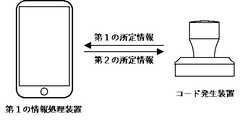
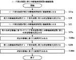
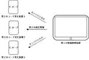
(26)さらに、(A)前記接続状態で、前記通信処理部から前記第1の情報処理装置に第1の所定情報を送信するか、前記第1の情報処理装置から前記通信処理部に第2の所定情報を送信するか、(B)前記通信処理部と、所定の方法により第2の情報処理装置とを接続状態にし、前記通信処理部から前記第2の情報処理装置に第3の所定情報を送信するか、前記第2の情報処理装置から前記通信処理部に第4の所定情報を送信するか、(C)前記第1の情報処理装置と、所定の方法により第3の情報処理装置とを接続状態にし、前記第1の情報処理装置から前記第3の情報処理装置に第5の所定情報を送信するか、前記第3の情報処理装置から前記第1の情報処理装置に第6の所定情報を送信するか、(D)前記第2の情報処理装置と、所定の方法により第3の情報処理装置とを接続状態にし、前記第2の情報処理装置から前記第3の情報処理装置に第7の所定情報を送信するか、前記第3の情報処理装置から前記第2の情報処理装置に第8の所定情報を送信するか、の少なくともいずれかである、情報通信方法、を特徴とする。 (26) Further, (A) in the connected state, the first predetermined information is transmitted from the communication processing unit to the first information processing device, or the first information processing device transmits the first predetermined information to the communication processing unit. (B) The communication processing unit and the second information processing apparatus are connected to each other by a predetermined method, and the communication processing unit transmits the third information to the second information processing apparatus. Whether predetermined information is transmitted, fourth predetermined information is transmitted from the second information processing apparatus to the communication processing unit, or (C) third information is transmitted by the first information processing apparatus and a predetermined method. The processing apparatus is connected to the first information processing apparatus, and the fifth predetermined information is transmitted from the first information processing apparatus to the third information processing apparatus, or the third information processing apparatus is transmitted to the first information processing apparatus. Transmitting sixth predetermined information, or (D) the second information processing apparatus; The third information processing device is connected to the third information processing device by a predetermined method, and the seventh predetermined information is transmitted from the second information processing device to the third information processing device, or from the third information processing device. An information communication method is characterized in that at least one of eighth predetermined information is transmitted to the second information processing apparatus.
(27)さらに、前記通信処理部に、一意の装置IDまたは、前記電極コードと組み合わせて一意となる装置IDが記憶され、前記第1または第3の所定情報の少なくともいずれかに該装置IDを含む、情報通信方法、を特徴とする。 (27) Furthermore, a unique device ID or a unique device ID in combination with the electrode code is stored in the communication processing unit, and the device ID is stored in at least one of the first and third predetermined information. Including an information communication method.
(28)さらに、前記電極コードと組み合わせて一意となる装置IDは、該装置IDが一意であり、前記第1の情報処理装置が該組み合わせとは異なる該電極コードを認識した場合、該電極コードを誤認として判定する、情報通信方法、を特徴とする。 (28) Further, the device ID that is unique in combination with the electrode code is unique when the device ID is unique, and when the first information processing apparatus recognizes the electrode code different from the combination, the electrode code Is characterized by an information communication method for determining as a misconception.
(29)さらに、前記第1〜第3の情報処理装置の少なくともいずれかに、該情報処理装置を特定する第1の特定コードおよび/または稼働するソフトウェアで設定された第2の特定コードを有し、前記特定コードを有する前記情報処理装置から送信される前記第2、第4、第5、第6、第7および第8の所定情報の少なくともいずれかに、前記第1または第2の特定コードのいずれかを含む、情報通信方法、を特徴とする。 (29) Furthermore, at least one of the first to third information processing apparatuses has a first specific code for specifying the information processing apparatus and / or a second specific code set by software that operates. And at least one of the second, fourth, fifth, sixth, seventh, and eighth predetermined information transmitted from the information processing apparatus having the specific code, the first or second specific An information communication method including any of the codes.
(30)さらに、前記第1の情報処理装置は、前記電極コードの少なくとも1部を含む通信アドレス、または該電極コードの少なくとも1部に対応する通信アドレスを認識して、1以上の前記第3の情報処理装置と接続状態にする、情報通信方法、を特徴とする。 (30) Furthermore, the first information processing apparatus recognizes a communication address including at least a part of the electrode code or a communication address corresponding to at least a part of the electrode code, and the one or more third information An information communication method for connecting to an information processing apparatus.
(31)さらに、前記第3の情報処理装置は、前記第2の情報処理装置を含む、情報通信方法、を特徴とする。 (31) Further, the third information processing apparatus is characterized by an information communication method including the second information processing apparatus.
(32)さらに、請求項1〜21のいずれかに記載の前記装置および前記第1〜第3の情報処理装置が受信した前記第1〜第8の所定情報の少なくともいずれかの正誤を所定の方法で判定する、情報通信方法、を特徴とする。 (32) Furthermore, at least one of the first to eighth predetermined information received by the device according to any one of
(33)さらに、前記所定の方法で判定された結果が前記受信した前記所定情報を送信元に送信する、情報通信方法、を特徴とする。 (33) Further, the information communication method is characterized in that a result determined by the predetermined method transmits the received predetermined information to a transmission source.
(34)さらに、前記第1〜第8の所定情報の少なくともいずれかは、所定のデータと該所定のデータを暗号化した暗号化情報を含む、情報通信方法、を特徴とする。 (34) Further, the information communication method is characterized in that at least one of the first to eighth predetermined information includes predetermined data and encrypted information obtained by encrypting the predetermined data.
(35)さらに、前記暗号化情報は、前記所定のデータを符号化手段により符号化した符号化情報を暗号化手段により暗号化した情報である、情報通信方法、を特徴とする。 (35) Further, the information communication method is characterized in that the encrypted information is information obtained by encrypting the predetermined data encoded by the encoding means using the encryption means.
(36)さらに、前記所定情報を受信した情報処理装置により、前記暗号化情報を復号化手段により復号した符号化情報と、前記所定のデータを前記符号化手段により符号化した符号化情報とを照合することにより前記所定のデータの正誤を認証する、情報通信方法、を特徴とする。 (36) Furthermore, the information processing apparatus that has received the predetermined information includes: encoded information obtained by decoding the encrypted information by decoding means; and encoded information obtained by encoding the predetermined data by the encoding means. An information communication method for authenticating the correctness of the predetermined data by collating.
(37)さらに、前記第1〜第8の所定情報の少なくともいずれかを送信または受信した際に、対応する所定の処理を実施する、情報通信方法、を特徴とする。 (37) Further, the information communication method is characterized in that when at least one of the first to eighth predetermined information is transmitted or received, a corresponding predetermined process is performed.
(38)さらに、前記所定の処理は、前記第3の情報処理装置と前記第1または第2の情報処理装置との接続状態、または前記通信処理部と前記第1の情報処理装置および/または第2の情報処理装置との接続状態の少なくともいずれかを切断する処理を含む、情報通信方法、を特徴とする。 (38) Further, the predetermined processing may be a connection state between the third information processing device and the first or second information processing device, or the communication processing unit and the first information processing device, and / or An information communication method including a process of disconnecting at least one of the connection states with the second information processing apparatus.
(39)さらに、前記通信処理部に時計機能を備えて、時間情報または時間によって変化する情報を前記第1および/または第3の所定情報に含む、情報通信方法、を特徴とする。 (39) The information communication method further includes a clock function in the communication processing unit, and includes time information or information that changes according to time in the first and / or third predetermined information.
(40)本発明にかかる装置と、物理量の変化を検出して1以上の位置を検知するタッチパネルを接続した第1の情報処理装置と、を備えた情報通信システムであって、前記タッチパネルに前記装置の筐体底面部に配置された複数の電極を接触または略接触させて、該複数の電極の内、該タッチパネルが検知した電極によって形成される電極コードを前記第1の情報処理装置が認識し、前記装置の筐体に備えられた通信処理部と、前記電極コードの少なくとも1部に基づき前記第1の情報処理装置とが接続状態となる、情報通信システム、を特徴とする。 (40) An information communication system comprising: an apparatus according to the present invention; and a first information processing apparatus connected to a touch panel that detects a change in physical quantity and detects one or more positions. The first information processing apparatus recognizes an electrode code formed by an electrode detected by the touch panel among the plurality of electrodes by contacting or substantially contacting a plurality of electrodes arranged on the bottom surface of the casing of the apparatus And an information communication system in which the communication processing unit provided in the housing of the device is connected to the first information processing device based on at least one part of the electrode cord.
(41)本発明にかかる情報通信方法で、前記通信処理部と前記第1の情報処理装置とが接続状態となる情報通信システム、を特徴とする。 (41) The information communication method according to the present invention is characterized by an information communication system in which the communication processing unit and the first information processing apparatus are in a connected state.
(42)さらに、第2および/または第3の情報処理装置をさらに備え、
請求項26〜38のいずれかに記載された情報通信方法により情報処理される、情報通信システム、を特徴とする。(42) Further, a second and / or third information processing device is further provided,
An information communication system processed by the information communication method according to any one of
(43)さらに、前記第1の情報処理装置はスマートフォンである、情報通信システム、を特徴とする。 (43) Further, the first information processing apparatus is characterized by an information communication system that is a smartphone.
(44)さらに、第1の情報処理装置に接続された、物理量の変化を検出して1以上の位置を検知するタッチパネルに、本発明にかかる前記装置の筐体底面部に配置された複数の電極を接触または略接触させて、該複数の電極の内、該タッチパネルが検知した電極によって形成される電極コードを前記第1の情報処理装置が認識し、前記電極コードの少なくとも1部に基づき、本発明にかかる情報通信方法で、前記第1の情報処理装置と前記装置の筐体に備えられた通信処理部とを接続状態にする、プログラム、を特徴とする。 (44) Further, a plurality of touch panels connected to the first information processing apparatus that detect one or more positions by detecting a change in physical quantity are arranged on the bottom surface of the casing of the apparatus according to the present invention. The first information processing device recognizes an electrode code formed by an electrode detected by the touch panel among the plurality of electrodes by contacting or substantially contacting the electrode, and based on at least a part of the electrode code, The information communication method according to the present invention is characterized in that the first information processing apparatus and a communication processing unit provided in a casing of the apparatus are connected.
(45)さらに、第2および/または第3の情報処理装置をさらに備え、本発明にかかる情報通信方法により情報処理を実施する、プログラム、を特徴とする。 (45) The program further includes a second and / or third information processing apparatus, and performs information processing by the information communication method according to the present invention.
本発明によれば、情報処理装置のタッチパネルに接触または略接触させるコード発生装置を多数提供でき、それらのコード発生装置を情報処理装置で特定できる。 ADVANTAGE OF THE INVENTION According to this invention, many code | cord generators which make the touch panel of information processing apparatus contact or substantially contact can be provided, and those code | cord generators can be specified by information processing apparatus.
以下、図面を参照しながら、本発明の実施形態について説明する。 Hereinafter, embodiments of the present invention will be described with reference to the drawings.
[情報処理システムの概要]
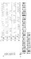
図1は、本発明の一実施形態に係る情報処理システムの外観的構成の一例を示す図である。[Outline of information processing system]
FIG. 1 is a diagram illustrating an example of an external configuration of an information processing system according to an embodiment of the present invention.
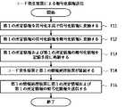
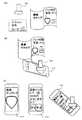
図1に示す情報処理システムは、コードを発生するコード発生装置1と、当該コードを認識するコード認識装置3と、当該コードに関する所定の処理を実行するサーバ4とを備えている。 The information processing system shown in FIG. 1 includes a
コード認識装置3とサーバ4は、インターネット等の所定のネットワークNを介して接続されている。 The
図1に示す様に、コード認識装置3は、タッチパネル31を有するスマートフォン、またはタブレット等の情報処理装置で構成される。タッチパネル31は、表示部と、当該表示部の表示面に積層される静電容量式の位置入力センサとから構成される。タッチパネル31には、コード発生装置1により出力されたパターンコードを示す電極群を検知する領域SP(以下、「コード検知領域SP」と呼ぶ)が表示される。 As shown in FIG. 1, the
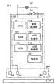
コード認識装置3は、図示しない機能ブロックとして、検知部と、認識部とを備えている。 The
なお、機能ブロックは、ハードウェア単体で構成してもよいが、本実施形態ではソフトウェアとハードウェアとにより構成されるものとする。つまり、検知部と認識部は、ソフトウェアとハードウェアとが協働することにより、次のような機能を発揮するものとする。 In addition, although a functional block may be comprised with a hardware single body, in this embodiment, it shall be comprised with software and hardware. That is, the detection unit and the recognition unit exhibit the following functions by cooperation of software and hardware.
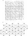
検知部は、タッチパネル31のコード検知領域SPに対して、コード発生装置1により人体と低インピーダンスで接続した1以上の電極5が接触又は近接した場合、位置入力センサの検知結果に基づいて、当該1以上の電極5の配置情報である導電パターンを検知する。 When one or
認識部は、検知された1以上の電極の導電パターンに基づいて、コード発生装置1のコード発生部により発生されたパターンコードを認識する。 The recognition unit recognizes the pattern code generated by the code generation unit of the
このパターンコードは、必要に応じてサーバに送信される。 This pattern code is transmitted to the server as necessary.
サーバは、当該パターンコードに基づいて各種処理を実行する。 The server executes various processes based on the pattern code.
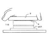
[コード発生装置の概要]
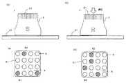
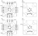
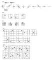
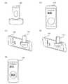
図2は、コードを切替可能なコード発生装置1の構成の一例を示す模式図である。[Outline of code generator]
FIG. 2 is a schematic diagram illustrating an example of the configuration of the
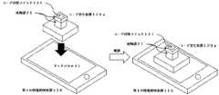
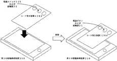
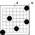
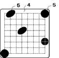
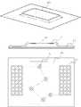
具体的には、図2(A)は、コード発生装置1がタッチパネル31に接面された状態の概略側面図である。図2(B)は、コード発生装置1がタッチパネル31に接面された状態のコード発生装置1の底面4にある電極5の状態を示す概略図である。図2(C)は、コード発生装置1がタッチパネル31上で人の手によって、タッチパネル31のパネル面に押圧された状態の概略側面図である。図2(D)は、コード発生装置1がタッチパネル31上で人の手によって、タッチパネル31のパネル面に押圧された状態のコード発生装置1の底面4にある電極5の状態を示す概略図である。 Specifically, FIG. 2A is a schematic side view of a state where the
なお、図2(B)、図2(D)において示されている電極51は、タッチパネル31によって検知されていない状態、斜線で示されている電極52は、タッチパネル31によって検知されている状態を示す。 2B and 2D, the
図2(A)および図2(B)に示されるように、コード発生装置1は、例えば人の手によって筐体2の少なくとも一部に設けられた導電性材料で形成された人体接触導電材21に触れながらタッチパネル31に接面された状態(STEP1)では、非導電性基材で作成された底面4に形成された複数の電極5が、例えばコード発生装置1毎に割り振られたIDパターンコードである第1の導電パターン81に対応する電極5をタッチパネル31に対し検知させることでパターンコードを発生させる。図2(B)の場合、4×4に等間隔で配列された16個の電極5の内の特定位置の3個の電極52を第1の導電パターンとして後述する方法でタッチパネル31に対し検知させている。 As shown in FIGS. 2 (A) and 2 (B), the
コード発生装置1の底面に配列する電極5の数および配置および、導電パターンとしてタッチパネル31に検知させる電極52の数および配置は、コード認識装置3がパターンコードとして識別できるものであれば良く、限定されるものではない。ただし、コード認識装置3がスマートフォンである場合は、一度に検知させる電極52は、最大5個以内であることが好ましい。これは、コード認識装置3がスマートフォンの場合にタッチパネル31に同時に検知される座標を最大5か所までとし、それを超えるとエラー処理を行う制御を実施するものに対応するためである。言うまでもなく、コード認識装置3が5を超える電極を検知する機能を有すれば、この限りではない。 The number and arrangement of the
図2(A)の状態からコード発生装置1に対し所定の操作を行うことにより、次の状態に移行する。 A predetermined operation is performed on the
図2(C)および図2(D)に示されるように、コード発生装置1は、例えば所定の操作である人の手によって筐体2の少なくとも一部に設けられた導電性材料で形成された人体接触導電材21に触れながらタッチパネル31に押圧された状態(STEP2)では、非導電性基材で作成された底面4に形成された複数の電極5が、例えばコード認識装置3が行う処理に割り振られたアクティブパターンコードである第2の導電パターン82に対応する電極5をタッチパネル31に対し検知させることでパターンコードを発生させる。図2(D)の場合、4×4に等間隔で配列された16個の電極5の内の特定位置の5個の電極52を第2の導電パターン82として後述する方法でタッチパネル31に対し検知させている。 As shown in FIGS. 2C and 2D, the
第2の導電パターン82としてタッチパネル31に検知させる電極52の数と配置も、コード認識装置3がパターンコードとして識別できるものであれば良く、特に限定されるものではない。ただし、コード認識装置3がスマートフォンである場合は、一度に検知させる電極52は、最大5個以内であることが好ましい。言うまでもなく、コード認識装置3が5個を超える電極を検知する機能を有する装置が対象であれば、この限りではない。 The number and arrangement of the
また、第1の導電パターン81と第2の導電パターン82でタッチパネル31に検知させる電極52の配置と数は、それぞれ独立に設定可能である。 Further, the arrangement and number of the
また、コード発生装置1は、所定の操作を行うことにより、図2(A)の状態から図2(C)の状態に移行する期間の中間の状態では、例えば人の手によって筐体2の少なくとも一部に設けられた導電性材料で形成された人体接触導電材21に触れた状態であっても底面4に形成された全ての電極5は、(後述の基準電極54がある場合、基準電極54を除き)いずれもタッチパネル31に検知されない状態となる。 In addition, the
[パターンコード切り替え方法の概要]
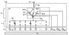
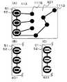
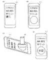
図3(A)に第1の導電パターン81と第2の導電パターン82を切替可能なコード発生装置1の基本回路概略である。図3(B)は、図3(A)のパターンコード切替状態を説明する図である。切替方法説明のための基本構成例であり、電極は、2×2個の配列としている。[Overview of pattern code switching]
FIG. 3A is a schematic basic circuit diagram of the
コード発生装置1は、操作部6である押しボタンスイッチ60と設定部7である第1コードスイッチ71と第2コードスイッチ72、電極5、人体接触導電材21を備える。 The
電極5は、第1の導電パターン81と第2の導電パターン82のパターンコード設定に対しタッチパネル31が検知、非検知を切替可能とするコード電極53と、全てのパターンコード設定に対し常にタッチパネル31が検知するようにした基準電極54を設けることが出来る。基準電極54は、コード認識装置3がコード認識に必要としない場合、特に設ける必要はなく、全ての電極5をコード電極53とすることが出来る。 The
操作部6である押しボタンスイッチ60は、SPDT型(入力1系統、出力2系統)のA/B切替スイッチをコード電極53に対応するn極分をまとめて1つの押しボタンの押圧動作で切り替え可能としたものである。 The
共通端子であるC端子を電極5と導線もしくは導電体で接続し、初期状態オンしているA端子を第1の導電パターン81の設定部7である第1コードスイッチ71に接続し、押圧時にオンするB端子を第2の導電パターン82の設定部である第2コードスイッチ72と導線もしくは導電体で接続する。 The C terminal, which is a common terminal, is connected to the
操作部6の押しボタンスイッチ60は、押しボタンスイッチに限定されるものではなく、所定の操作を受けた時に、第一の導電パターン81を設定する端子から第二の導電パターン82を設定する端子に切り替える機能を有していれば良い。 The
また、操作部6の押しボタンスイッチ60は、コード発生装置1の筐体2の外部から所定の操作である押しボタンの押圧操作を行うことが出来る。 Further, the
設定部7である第1コードスイッチ71、第2コードスイッチ72は、SPST型(入力1系統、出力1系統)のON/OFFのスライドスイッチをコード電極53に対しそれぞれ設けたもので、第1コードスイッチ71は、一方の端子を操作部のA端子に接続されている導線もしくは導電体と接続し、他端子を人体接触導電材21に導線もしくは導電体で接続し、第2コードスイッチ72は、一方の端子を操作部のB端子に接続されている導線もしくは導電体と接続し、他端子を人体接触導電材21に導線もしくは導電体で接続する。 The
設定部7の第1コードスイッチ71、第2コードスイッチ72は、スライドスイッチに限定されるものではなく、パターンコードに対応する第1の導電パターン81および第2の導電パターンでタッチパネル31に検知される位置にある電極5に接続されている一方の端子を人体接触導電材21に接続し、検知されない位置にある電極5に接続されている一方の端子を人体接触導電材21から切り離すことで、検知される電極5を選択しパターンコードを設定する機能を有していれば良い。 The
また、設定部7は、第1コードスイッチ71、第2コードスイッチ72のそれぞれをコード発生装置1の筐体2の外部から設定出来るようにしても良いし、どちらか一方または両方のコードスイッチを外部からは設定できないようにしても良い。 In addition, the
人体接触導電材21は、コード発生装置1の筐体2の外側から接触可能に設けられ、設定部7の前記他端子に接続されている導線もしくは導電体を全て接続する。また、全てのパターンコード設定に対し常にタッチパネル31が検知するようにした基準電極54を設ける場合は、電極に接続されている導線もしくは導電体を直接人体接触導電材21に接続する。 The human body contact
また、コード発生装置1は、電極5から人体接触導電材21までの間に、操作部6(押しボタンスイッチ60)の切替え機能と、設定部7(第1,第2コードスイッチ71,72)の選択機能が設けられていれば良く、電極5から設定部7、操作部6、人体接触導電材21の順で接続しても良い。 Further, the
さらに、操作部6の切り替え機能だけを設けても良く、設定部7の選択機能だけを設けても良い。 Further, only the switching function of the
図3(B)は、図3(A)のコード発生装置1でコード発生の切替操作を行った時の電極5の状態を示す図である。 FIG. 3B is a diagram illustrating a state of the
STEP1で、コード発生装置1を例えば人の手によって筐体2の人体接触導電材21に触れながらタッチパネル31に接面すると、電極53のNo.2は、人体接触導電材21、第1コードスイッチ71のスイッチ2、押しボタンスイッチ60のAおよびC端子を経由し、人の手と低インピーダンスで繋がり、タッチパネル31−電極53間の静電容量を変化させて、タッチパネル31により検知される。また、No.0の基準電極54は、人体接触導電材21から直接人の手と低インピーダンスで繋がるため、同様にタッチパネル31により検知される。基準電極54を設けることにより、導電パターンの向きならびにパターンコードを特定するのが容易となる。 In
電極53のNo.1は、第1コードスイッチ71のスイッチ1がオフしているため、電極53および第1コードスイッチ71までの寄生静電容量がタッチパネル31−電極53間の静電容量を変化させるが、寄生静電容量によるタッチパネル31−電極53間の静電容量の変化量を検知の閾値以下に抑えることによりタッチパネル31により検知されない。 No. of
これらより、電極のNo.0と2がタッチパネル31に検知された第1の導電パターン81のパターンコードが生成される。 From these, the electrode No. A pattern code of the first
STEP2で、コード発生装置1を例えば所定の操作である人の手によって筐体2の人体接触導電材21に触れながらタッチパネル31に押圧し、押しボタンスイッチ60の2個のA端子とC端子の接続がB端子側に切り替わると、第2コードスイッチ72のスイッチ1がオン、スイッチ2がオフしているため、電極53のNo.1が人体接触導電材21に接続し、No.2は、第2コードスイッチ72のスイッチ2で切り離される。また、No.0の基準電極54の接続関係は、STEP1から変わらない。 In
このため、電極のNo.0と1がタッチパネル31に検知された第2の導電パターン82のパターンコードが生成される。 For this reason, the electrode No. A pattern code of the second
また、STEP1からSTEP2への移行時に一時的に第1、第2の導電パターン81、82と異なるパターンコードを発生させてしまい、コード認識装置3で誤認識が発生するのを防止するため、また、多数の電極53を同時にタッチパネル31に検知させてしまい、コード認識装置3でのタッチパネル31が同時に検知可能な最大数であるマルチタッチ数の制約に違反しないため、押しボタンスイッチ60押圧途中の状態で、A,B端子ともにC端子に接続されない状態を作り、基準電極54以外の全ての電極53が人体接触導電材21から切り離され、タッチパネル31により検知されない状態を作る、いわゆるノンショーティングタイプの切り替え方式であることが好ましい。 In addition, in order to prevent the
これらの理由から、導電パターンを切り替え可能とする操作部6の各種スイッチは、ノンショーティングタイプの切り替え方式であることが好ましい。 For these reasons, it is preferable that the various switches of the
[パターンコード復号化方法の概要]
コード発生装置1が発生させる第1、第2の導電パターン81、82は、例えば以下の2つの方法で電極導電パターンを発生させることにより、コード認識装置3がパターンコードとしてコードを識別し情報を取得することが可能となる。[Outline of pattern code decoding method]
The first and second
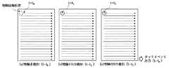
1つ目のパターンコード化の方法としては、第1の導電パターン81のタッチパネル31に検知された電極52(以下、オン電極52とする)の検知された位置情報から第1のパターンコードを確定し、さらに、第1の導電パターンのオン電極52を基準パターンとして、各電極5の配列、相対位置を取得し、その配列、相対位置を元に第2の導電パターン82のオン電極52の配列、相対位置を確定し、その位置情報から第2のパターンコードを確定する方法がある。 As a first pattern encoding method, the first pattern code is determined from the detected position information of the electrode 52 (hereinafter referred to as the ON electrode 52) detected on the
この方法は、例えば図2に示すコード発生装置1の様に押圧という所定の操作によって第1の導電パターン81と第2の導電パターン82の発生順が決まり第1の導電パターン81が第2の導電パターン82よりも先行して発生する場合に適用できる。この方法の場合、第2の電極パターン82では、ユニークなパターンコードとするための複数のオン電極52配置に関する導電パターンの制約は無くなり、選択できる第2の導電パターン82の数は、選択できる第1の導電パターン81の数に対し大幅に増大する。総パターンコード数は、共に複数ある第1の導電パターン81と第2の電極パターン82の掛け算となるため、飛躍的に増大させることが出来る。 In this method, for example, the order of generation of the first
2つ目のパターンコード化の方法としては、第1の導電パターン81と第2の導電パターン82をそれぞれ独立なものとして、それぞれのオン電極52が検知された位置情報からそれぞれ独立に第1の導電パターン81と第2の導電パターン82から第1のパターンコードと第2のパターンコードを確定する方法である。この方法は、例えば後述の実施の形態6、実施の形態7の様に人体接触導電材21を複数設け、人体接触導電材21に触るか触らないかで第1の導電パターン81と第2の導電パターン82を切り替え可能とするような構成で、第1の導電パターン81と第2の導電パターン82の発生順が任意に選択可能な場合に適用される。 As a second pattern coding method, the first
また、言うまでもなく順番が決まっている図2に示すコード発生装置1の様な場合でも2つ目のパターンコード化の方法も適用可能である。 Needless to say, the second pattern coding method can also be applied to the case of the
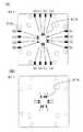
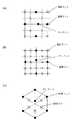
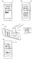
図4から図9を参照して、コード認識装置3による電極5の位置認識方法およびこの位置認識方法にしたがうプログラムの処理を例示する。本実施形態では、コード認識装置3は、タッチパネル31のコード検知領域SPで検知された5個の電極5(導体)のすべてを情報導体として導電パターンを認識し、5個の検知点でパターンコードを定義・取得する。 With reference to FIG. 4 to FIG. 9, the method of recognizing the position of the
(アルゴリズムの詳細)
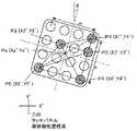
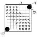
(ステップE1)図9にアルゴリズムの詳細を例示する。本実施例においても、図5のタッチパネル上の座標系での検知点の座標値は、P1(X1’,Y1’),P2(X2’,Y2’),P3(X3’,Y3’),P4(X4’,Y4’),P5(X5’,Y5’)とする。情報機器200は、検知したID領域の5点の内の2点間の距離をすべて計算する。2点間の距離の長い方からL1〜L10としてソートする。ソートの結果は、L1>L2>L3>L4>L5>L6>L7>L8>L9>L10となる。なお、図5のXY座標系は、タッチ領域の左下を原点とした座標形である。また、図5においては、コード発生装置1をタッチパネルにθ回転して載置した際の各検知点の座標値は、タッチパネルのX’Y’座標系で表している。検知2点を結ぶ最長線分L1は、P1とP5からなり、コード発生装置1の正方向(Y軸方向)に対してL1の角度θ1を成している。θ1は、検知2点を結ぶ最長線分に対応する情報の1つとして予めコード認識装置3に設定され、例えば、ROMに記憶されている。(Details of algorithm)
(Step E1) FIG. 9 illustrates details of the algorithm. Also in this embodiment, the coordinate values of the detection points in the coordinate system on the touch panel of FIG. 5 are P1 (X1 ′, Y1 ′), P2 (X2 ′, Y2 ′), P3 (X3 ′, Y3 ′), Let P4 (X4 ′, Y4 ′) and P5 (X5 ′, Y5 ′). The information device 200 calculates all the distances between two points out of the five points in the detected ID area. Sort as L1 to L10 from the longest distance between two points. The result of sorting is L1>L2>L3>L4>L5>L6>L7>L8>L9> L10. Note that the XY coordinate system in FIG. 5 is a coordinate form with the origin at the lower left of the touch area. In FIG. 5, the coordinate values of each detection point when the
(ステップE2)検知点5点によるコードの認識では、先ず、コード認識装置3は、検知2点を結ぶ最長線分L1を構成する始点PSと終点PE(本変形例では、P5とP1)を求める。コード発生装置1を傾けて載置した場合のタッチパネルY’方向に対する、PSを始点とした2点PS,PEを結ぶ線分の角度は、θ’=tan−1{(Y1’−Y5’)/(X1’−X5’)となる。 (Step E2) In the code recognition by the five detection points, first, the
(ステップE3)コード認識装置3は、PSを原点とし、L1で基準化した他の4点の検知点の相対座標値ΔP1{ΔX1’=(X1’−X5’)/L1,ΔY1’=(Y1’−Y5’)/L1},ΔP2{X2’=(X2’−X5’)/L1,ΔY2’=(Y2’−Y5’)/L1},ΔP3{ΔX3’=(X3’−X5’)/L1,ΔY3’=(Y3’−Y5’)/L1},ΔP4’{ΔX4’=(X4’−X5’)/L1,ΔY4’=(Y4’−Y5’)/L1}を求める。 (Step E3) The
さらに、コード認識装置3は、図6のように、タッチパネル上の座標値を−θ’回転させて座標変換を行う。この座標変換後の座標を基準化座標と呼び、座標変換後の座標値を基準化座標値と呼ぶ。ここで、始点と終点との判別ができないため、P5とP1のそれぞれを原点とした各検知点の座標値を求める。 Furthermore, the
(ステップE4)そして、コード認識装置3は、最長線分L1を構成する始点PSと終点PEを除く3点の基準化座標値を事前に算出し、最長線分L1のコード発生装置1の正方向(Y軸方向)に対する角度θ1に対応づけて基準化座標−コード番号テーブルに記憶している。コード認識装置3は、最長線分L1のコード発生装置1の正方向(Y軸方向)に対する角度θ1と基準化座標−コード番号テーブルに記憶された最長線分の角度θ1を照合する。 (Step E4) Then, the
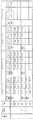
図8は基準化座標−コード番号テーブルの例である。5個のSP領域の電極5の配置座標について、最長線分L1の角度θ1ごとに、始点PSと終点PEを除く3点の基準化座標値を計算し、ROMに格納している。図で、「原点座標系」のフィールドは、最長線分L1の端点P1、P5のいずれを原点するかによって決まり2つの座標系を示す。「コード番号」のフィールドは、図8の表の各行で決定されるパターンコードを示す。「最長線分の角度θ1」のフィールドは、最長線分L1のコード発生装置1の正方向(Y軸方向)に対する角度θ1である。コード認識装置3は、最長線分L1の長さと角度θ1との対応表をRAMまたはROMに保持しているので、最長線分L1の長さを算出すれば、角度θ1を求めることができる。「判定範囲半径」は、図8の表で特定される座標値と、コード認識装置3がタッチパネルから取得した3点の位位置座標の許容誤差である。「情報導体座標1」から「情報導体座標3」は、最長線分L1の端点P1、P5以外の3点の座標が照合される基準化座標値である。コード認識装置3は、最長線分L1の角度θ1が一致し、かつ、最長線分L1の端点P1、P5以外の3点の座標が情報導体座標1から情報導体座標3に判定範囲半径の誤差範囲で合致したときに、当該行のコード番号をパターンコードとして特定する。 FIG. 8 is an example of a standardized coordinate-code number table. With respect to the arrangement coordinates of the
所定誤差は、タッチパネルの検知解像度の影響が多くを占めており、その誤差は実寸での絶対値となる。一方、各検知座標は、検知2点を結ぶ最長線分L1で基準化しているため、ID(つまり、L1の距離)によって誤差範囲が一定でなくなる。そこで、図8には、基準化された座標値でも適正な合致の判定のために、基準化座標−コード番号テーブルに誤差範囲半径rが設定されている。コード認識装置3は、テーブル内の座標値(I,J)を中心に半径r内に納まれば合致として判定する。なお、コード認識装置3は、この誤差範囲は矩形で設定・判定してもよい。 The predetermined error is largely influenced by the detection resolution of the touch panel, and the error is an absolute value in actual size. On the other hand, since each detection coordinate is standardized by the longest line segment L1 connecting the two detection points, the error range is not constant depending on the ID (that is, the distance of L1). Therefore, in FIG. 8, an error range radius r is set in the standardized coordinate-code number table in order to determine proper matching even with the standardized coordinate values. The
(ステップE4)そして、コード認識装置3は、得られた座標値からパターンコード(ID)と、タッチ位置番号を特定し、対応する処理を実行する。 (Step E4) Then, the
(効果)以上のように、コード認識装置3は、図8の基準化座標−コード番号テーブルで照合し、所定の誤差範囲で合致した際に当該コード番号であるパターンコードを求まることができる。したがって、コード認識装置3は、求めたパターンコードに対応する様々な処理を実行できる。 (Effects) As described above, the
[切替可能な電極に対する制約の検討概要]
パターンコード切り替え方法の説明より、コードを切替可能なコード発生装置1では、操作部6の押しボタンスイッチもしくは設定部7の第2コードスイッチ72で人体接触導電材21から切り離されているが、タッチパネル31に接している電極5の寄生静電容量を含む電極5−タッチパネル31間の静電容量を小さくし、タッチパネル31の静電容量の変化量が検知の閾値を超えないようにすることが重要であることが解る。[Summary of restrictions on switchable electrodes]
From the description of the pattern code switching method, the
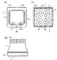
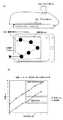
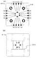
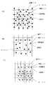
このため、電極がタッチパネルに検知されないために許容される静電容量を評価した。図10は、評価基板の概略図である。図10(A)は、電極が人体側に多く寄生静電容量が付く場合を想定した評価基板の上面図で、図10(B)は、電極がタッチパネルに多く寄生静電容量が付く場合を想定した評価基板の上面図で、図10(C)は、両方の基板の底面図である。 For this reason, the capacitance allowed because the electrodes were not detected by the touch panel was evaluated. FIG. 10 is a schematic view of an evaluation board. FIG. 10A is a top view of the evaluation board assuming that the electrode has many parasitic capacitances on the human body side, and FIG. 10B shows the case where the electrode has many parasitic capacitances on the touch panel. 10C is a top view of the assumed evaluation board, and FIG. 10C is a bottom view of both boards.
基板は、厚さ1.5mmのPCB基板で、底面に直径8mmの電極を縦12mm、横14mmの間隔で3×4で配列してある。電極は、スルーホールで上面の直径3mmのランドパターンに接続し、上面には、電極に寄生静電容量を持たせる基板配線を(A)では、電極とオーバーラップを持つように、(B)では、電極とオーバーラップしないように幅0.1mm配線で引き回してある。 The substrate is a PCB substrate having a thickness of 1.5 mm, and electrodes having a diameter of 8 mm are arranged on the bottom surface at a size of 3 × 4 at intervals of 12 mm in length and 14 mm in width. The electrode is connected to a land pattern having a diameter of 3 mm on the upper surface through a through hole, and a substrate wiring for giving the electrode a parasitic capacitance on the upper surface is overlapped with the electrode in (A) (B) Then, it is routed by a 0.1 mm wide wiring so as not to overlap the electrode.
評価方法は、外周の5個の電極のランドパターンを追加配線で接続し、配線端を人が触れて検知(ON)電極とし、中央の1個の電極のランドパターンと基板上配線を接続し寄生容量の付いた非検知(OFF)電極とする。底面側をタッチパネルに接するように接面して、タッチパネルが外周5個の電極を正常に検知し、中央1個の電極が常に検知されない状態になるための中央1個の電極の静電容量を基板配線長を変更して評価した。 The evaluation method is to connect the land pattern of the outer five electrodes with additional wiring, touch the end of the wiring as a detection (ON) electrode, and connect the land pattern of one central electrode to the wiring on the board. A non-detection (OFF) electrode with parasitic capacitance is used. Touching the bottom side so that it touches the touch panel, the touch panel can detect the five outer electrodes normally, and the capacitance of the center one electrode is not always detected. Evaluation was made by changing the wiring length of the substrate.
タッチパネルの電極の検知、非検知判定は、評価基板を縦置き横置きにそれぞれ10回接面し、タッチパネルの出力が電極の座標を正しく返すかどうかで判定した。表1での表記は、5:全回正常検知、3:10回以上で正常検知、2:10回未満で正常検知、1:10回未満の検知でかつ5個の検知電極の一部が欠けているもの、0:10回とも非検知、E:10回以上でタッチパネル出力がエラーを返したもの、とした。 The touch panel electrode detection / non-detection determination was performed by touching the
コード認識装置3と使用環境は、iPhone(登録商標)6を手に持った場合と、電極を最も検知しづらいコルクボード上に置いた場合、iPad(登録商標)−Proをスチール机上に置いた場合とコルクボード上に置いた場合、の4条件とした。 The

評価の結果、表1で示すように、A、Bどちらの評価基板においてもiPhone(登録商標)6でいずれの条件でも電極−タッチパネル間の静電容量を5pF以下とすれば、電極は、タッチパネルに検知されないことが判った。また、5個の検知電極の配置のように密に検知される電極がある場合でもタッチパネルに正しく座標を検知されることが判った。この評価結果に基づいた仕様とすることでコードを切替可能なコード発生装置を作成することが出来る。 As a result of the evaluation, as shown in Table 1, if the capacitance between the electrode and the touch panel is 5 pF or less under any condition in iPhone (registered trademark) 6 on both evaluation boards A and B, the electrode is It was found that it was not detected. Further, it has been found that even when there are electrodes that are densely detected, such as the arrangement of five detection electrodes, the coordinates are correctly detected by the touch panel. By setting the specification based on the evaluation result, a code generator capable of switching codes can be created.
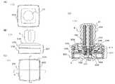
[実施の形態1]
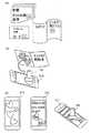
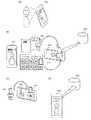
図11は、実施形態1のコード発生装置101の外形を示す概略図である。図11(A)は上面図、図11(B)は、側面図、図11(C)は、底面図である。図11(D)は、垂直方向に切った断面図である。図11に示すように、コード発生装置101は、四角いスタンプに似た形状としており、筐体2全体が操作部6の押しボタンスイッチの押しボタンとなっているため、筐体2を手で持ってタッチパネル31に接面し、押圧することで第1の導電パターン81、第2の導電パターン82の2種類のパターンコードを順次発生させることが出来る。手に持った状態で自然に触れることが出来るように筐体2上面を導電体で形成し人体接触導電材21としている。筐体2の側面には、タッチパネル31に接面する時の方向のガイドとしての突起22が設けられている。突起22を設けることにより、タッチパネル31に接面する方向を決めることができるため、タッチパネル31上にコード発生装置101の接面させる向きを表示させ、タッチパネル31上のコード発生装置101の接面する方向が常に固定された状態を前提として導電パターンを決めることが出来るようになり、これによりパターンコード数を増やすことも可能となる。[Embodiment 1]
FIG. 11 is a schematic diagram illustrating the outer shape of the
また、突起22の反対の側面には、ストラップ通し穴23が設けられている。底面4には、非導電体で形成された第1基板41があり、第1基板41の下面に設けられた電極5が底面4と同一平面上に、4×4の配列で配置されている。電極5の数および配列は、限定されるものではなく、必要なコードパターン数に応じて適宜増減可能である。 A strap through
また、第1基板41の下面に設けられた電極5は、全ての電極5同一平面上にあれば良く、第1基板41下面が凸状に形成されていても良い。 In addition, the
さらにまた、図11(C)の底面4には電極5が露出した状態の図となっているが、説明のためであり、実際の第1基板41の下面は、電極5を露出させないように、電極5の静電容量を大幅に低減させない程度に薄く有色の樹脂製のシートや薄板、PCB基板表面に塗布されるレジスト、もしくはコーティング印刷で覆い、電極5を保護するとともに、外見の意匠性を向上させることが好ましい。 Furthermore, although the
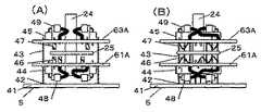
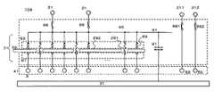
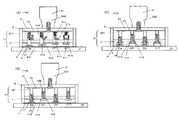
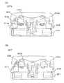
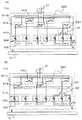
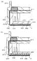
図12は、コード発生装置101の回路概略図である。図13は、コード発生回路101の電極5、操作部6、設定部7を形成するためPCB基板であり、(A)第1基板41の上面、(B)が第1基板41の下面、(C)が第2基板の上面、(D)が第2基板の下面、(E)が第3基板の上面、(F)が第3基板の下面のパターンである。図14は、コード発生装置101の操作部6である押しボタンスイッチの接点部分を垂直方向に切った断面図であり、(A)がタッチパネルに接面した状態(STEP1)、(B)が押しボタンを押圧した状態(STEP2)である。 FIG. 12 is a circuit schematic diagram of the
図11から図14に示すように、コード発生装置101は、設定部7の第1の導電パターン81を装置組み立て時点で選択的に設定し、第2の導電パターン82のみを第2コードスイッチ72にて変更可能に設定出来る仕様である。例えば、第1のパターンコードをコード発生装置101自体のIDコードとして使用する用途などが想定される。 As shown in FIG. 11 to FIG. 14, the
第1の導電パターン81は、第2基板61の上面に設けられた第1基板41の電極5から接続された第2基板電極端子62とパターン設定用端子73のうち第1の導電パターン81でタッチパネルに検知される電極に対応する端子のみを半田接合74で接続する方法で形成する。半田接合74が設定部7の第1コードスイッチ71のオンの機能に相当する。パターン設定用端子73はスルーホールを介し第1接点67に接続し、第1接点67は、可動電極25に対向している。可動電極25は、筐体2の導電体で筐体2と分離可能な状態で人体接触導電材21に接続される。 The first
第2の導電パターン82は、第3基板63の上面に設けられた電極5毎に設けられた設定部7の第2コードスイッチ72であるスライドスイッチ75をオンさせることで形成する。スライドスイッチ75は、筐体2内部の第3基板63上に設けられるため、筐体2と第3基板は、取り外し可能にネジ止めされる。第2の導電パターン82を変更する場合は、ネジを外して筐体2を開けスライドスイッチ75のオンオフを変更することで実施する。また、筐体2に設けられる人体接触導電材21と第3基板63上の共通接続線65は、ネジの組付け、取り外しに対応して接続、切り離しが可能な接点66を設ける。 The second
操作部6は、筐体2内部の中心軸24に分離可能に取り付けられた第3基板63と第3基板63と第2基板61の中心穴を通り第2基板61の下面側に設けられた導電体の可動電極25が筐体2の押圧動作に応じて第2基板61の間を可動することで第1のパターンコードから第2のパターンコードへの切替えを行う。可動電極25は、中心軸24を介して筐体2表面の人体接触導電材21に接続されている。 The
タッチパネル31に接面されたSTEP1の状態では、図14(A)に示すように、図示しない押しボタンスイッチのバネにより可動電極25と第3基板63は、上方に位置し、パターン設定用端子73と接続する第2基板61下面に電極5毎に設けられた第1接点67と可動電極25が接続状態であり、電極5毎に設けられた、第2基板61上面の第2基板側第2接点68と第3基板63下面の第3基板側第2接点69のペアは遮断された状態である。STEP1の状態で、各電極5のうち半田接合74が無いものは、第1基板41下面の電極5とタッチパネル31間の静電容量が、電極5から繋がっているパターン設定用端子73までの導電体の寄生静電容量も含めて、タッチパネル31が検知の閾値を超えない範囲で作られている。 In the state of
これにより、第2基板電極端子62とパターン設定用端子73間の半田接合74が有る電極5のみが人体接触導電材21まで導通状態となり第1の導電パターンが発生出来る。
次に、タッチパネル31に押圧されたSTEP2の状態では、図14(B)に示すように、押圧により可動電極25と第3基板63は、下方に位置し、第2基板61下面の第1接点67と可動電極25が遮断された状態であり、第2基板61上面の第2基板側第2接点68と第3基板63下面の第3基板側第2接点69のペアは接続状態である。STEP2の状態で、各電極5のうち、スライドスイッチ75がオフのものは、第1基板41下面の電極5とタッチパネル31間の静電容量が、電極5から繋がっているスライドスイッチ75の端子までの導電体の寄生静電容量も含めて、タッチパネル31が検知の閾値を超えない範囲で作られている。As a result, only the
Next, in the state of STEP2 pressed by the
これにより、第3基板63のスライドスイッチ75がオンの電極5のみが人体接触導電材21まで導通状態となり第2の導電パターンが発生出来る。 As a result, only the
また、押しボタンスイッチ60は、バネによる駆動機構を有する。駆動機構自体は、特に限定されるものではなく、一般的な押しボタンスイッチの機構を用いる事が出来るが、パターンコード切り替え方法の概要で説明した通り、第1、第2の導電パターン81、82の切り替え時に、少なくとも互いに異なる電極5は同時にタッチパネル31に検知されないことが必要であるため、ノンショーティングタイプの切り替え方式であることが好ましい。 The
さらに、コード発生装置101をタッチパネル31に接面させるときに底面4が均等に接面する前に押しボタンスイッチ60に押圧力が掛かり第1の導電パターン81がタッチパネル31に適正に検知されない状態を防止するため、押しボタンスイッチ60は、押しボタン駆動初期のトルクを適度に大きくし、クリック感を持たせると良い。 Further, when the
また、駆動機構は、モーメンタリ動作もしくはオルタネイト動作のどちらの動作方式を取ってもよい。 Further, the drive mechanism may take either a momentary operation or an alternate operation.
押しボタンスイッチ60押圧時に、第2基板61上面の第2基板側第2接点68と第3基板63下面の第3基板側第2接点69が16か所同時に接触すると、第3基板63のスライドスイッチ75のオフしているスイッチの片側端子までの寄生静電容量に貯まっている電荷が同時に検知させたくない電極5に伝わり、タッチパネル31の底面4が接面している領域全体に広く、微小ではあるがタッチパネル31の静電容量を変化させてしまい、誤検知の要因となる場合がある。このため、押しボタンスイッチのストローク長を長くし、接点68、69間隔を取り、16か所の接点間隔を複数の接点の組で変更し、押圧時の接点68、69の切り替わりを段階的に実施することで、誤検知を防止することが可能である When the
次に、設定部7で設定する第1の導電パターン81および、第2の導電パターン81でタッチパネル31に検知させる電極5の数と配置は、コード認識装置3がパターンコードとして認識出来る範囲でそれぞれの導電パターンで可変とすることが出来る。例えば、第1の導電パターン81では、5個の電極を検知させ、第2の導電パターン81は、2個しか検知させない仕様も可能である。これにより、選択できるパターンコードを大幅に増やすことが出来る。 Next, the number and arrangement of the first
また、複数ある第1、第2の導電パターン81、82のそれぞれの導電パターンの中では、タッチパネル31に検知させる電極5の数を固定することも出来る。このような仕様とすることで、選択できるパターンコード数は、可変の場合よりも減少するが、検知した電極5の数により検知エラー判定を行うことが可能となり、コード認識システムの信頼性を向上させることが出来る。 In addition, among the plurality of first and second
例えば、第1、第2の導電パターン81、82はどのパターンコードでもそれぞれ常に4個、5個の電極5を検知させるパターンコード仕様とし、コード認識装置3がコード復号化を行うときに、第1、第2の導電パターン81、82をそれぞれ検知、復号化処理する時に電極5の数がそれぞれ4個以外、5個以外の場合は全てエラーとして処理することが可能となり、容易にコードの誤検知を抽出発見出来る。 For example, the first and second
以上のことより、実施の形態1のコード発生装置101では、第1の導電パターン81と第2の導電パターン82の切り替えにより1つのコード発生装置101で複数のパターンコードを発生させることが出来るため発生させるパターンコード数を大幅に増やすことができる。 As described above, in the
また、第1の導電パターン81は、組み立て時の半田付け作業で、第2の導電パターンは、製品完成後のスライドスイッチのオンオフ切り替えで設定変更可能なため、パターンコード毎に金型や基板を変更する必要が無く、製造工程での製品に設定するパターンコードの変更に掛かる製造費用を大幅に低減し、変更TAT(ターンアラウンドタイム)も大幅に短縮できる。 The first
さらに、第2の導電パターンは、製品完成後のスライドスイッチのオンオフ切り替えという極めて簡便な方法で設定変更可能なため、コード設定方法を顧客に開示することで、顧客でもコード設定変更が可能となり、顧客の利便性も向上することが可能である。 Furthermore, since the second conductive pattern can be set and changed by an extremely simple method of switching on and off the slide switch after the product is completed, by disclosing the code setting method to the customer, the customer can change the code setting. Customer convenience can also be improved.
本実施形態では、第1の導電パターン81でタッチパネル31に検知させる電極5の設定を第2基板61上面の対応する第2基板電極端子62とパターン設定用端子73のみ半田接合74で接続する方法としたが、半田接合74の代わりにジャンパー配線で接続する方法としても良い。さらにまた、半田接合74の代わりに第2基板61の配線パターンで予め選択的に接続しておく方法としても良い。これにより、装置組み立て時の半田付け作業が不要となり、組み立て作業工程削減および組立時誤設定の低減により、製造費用の低減が可能となる。 In the present embodiment, the setting of the
本実施形態では、操作部6による1回の操作(例えば、1ストローク)で、設定部7によって設定された第1の導電パターン81から第2の導電パターン82に切り替える方式としたが、導電パターンを切り替える切り替え回数は、2回に限定されない。 In the present embodiment, the system is switched from the first
例えば、第2の導電パターン82でタッチパネル31に検知させる電極5を2組に分け、さらに操作部6の押しボタンスイッチ60の第2基板61上面の第2基板側第2接点68と第3基板63下面の第3基板側第2接点69の間隔を広げ、接点間隔を狭いものと広いものの2組に分け、押圧機構も2段階とすることで、押圧前の第1の導電パターン81と、押圧1段階目の第2の導電パターン82の接点間隔が狭い側の組の電極5のパターン、押圧2段階目の第2の導電パターン82で検知させる全ての電極5が検知されパターンの3段階の切り替えが可能となる。 For example, the
また、例えば、操作部6の押しボタンスイッチ60の押圧による第2基板61上面の第2基板側第2接点68と第3基板63下面の第3基板側第2接点69の切り替えを、多回路多接点のスライドスイッチもしくは、ダイヤルスイッチを各電極5に対応させ、第2基板側第2接点68を共通端子側、第3基板側2接点69(およびそれ以降の設定部7の構成)を複数設けて、スライドスイッチもしくは、ダイヤルスイッチの切替え接点側に接続し、所定の操作でスライドスイッチもしくは、ダイヤルスイッチを切り替えるようにすれば、多段階の切り替えが可能となる。 Further, for example, switching between the second substrate side
さらにまた、操作部6にリレーを動作させる電気的な制御回路を設け、操作部6の押しボタンスイッチ60によりリレーに依って第1、第2の導電パターン81,82の各電極5側の接点と人体接触導電材21の共通端子側の接点をリレーで切り替えるようにすることも出来る。 Furthermore, an electrical control circuit for operating the relay is provided in the
[実施の形態2]
図15は、コード発生装置102を垂直方向に切った断面図である。図16は、コード発生回路102の電極5、操作部6、設定部7を形成するためのPCB基板であり、(A)第1基板41の上面、(B)が第1基板41の下面、(C)が第2基板の上面、(D)が第2基板の下面、(E)が第3基板の上面、(F)が第3基板の下面のパターンである。[Embodiment 2]
FIG. 15 is a cross-sectional view of the
図15、図16に示すように、各電極5に対応する第2基板のパターン設定用端子73から配線を伸ばし、第2基板中央部に設けたスルーホール78を介して第2基板下面の中央に第1接点67を集める配置とし、また、第3基板63上面の共通接続線65から人体接触導電材21に接続する接点66も第3基板63の中央部に設けることで、可動接点25を小型化し電極面積を低減させ電極5に付く寄生容量の低減を図ると共に、筐体2の形状を中央柱状に設けることが可能となり、筐体2の導体部分である人体接触導電材21と電極5の間の寄生容量も低減できると共に、一般的な角型スタンプの形状に近い外形デザインとすることが出来る。 As shown in FIGS. 15 and 16, the wiring is extended from the
以上のことより、実施の形態2のコード発生装置102では、可動接点25を小型化し電極面積を低減させ電極5に付く寄生容量の低減することで、コード切り替わり動作時のタッチパネル31の誤検知を低減することが出来る。 As described above, in the
また、コード発生装置102の外形デザインに自由度を持たせることが出来るので、製品の意匠性を向上させることが出来る。 In addition, since the outer shape of the
また、言うまでもなく、実施の形態1のコード発生装置101同様に、第1の導電パターン81と第2の導電パターン82の切り替えによりパターンコード数を大幅に増やすことができる。組み立て時や、製品完成後にコードパターンの設定変更が可能なため、パターンコードの変更に掛かる製造費用低減、変更TATの短縮も可能であり、顧客の利便性も向上することが可能である。 Needless to say, the number of pattern codes can be greatly increased by switching between the first
[実施の形態3]
図17は、実施形態3のコード発生装置103の回路概略図である。図18は、コード発生回路103の電極5、操作部6、設定部7を形成するためPCB基板であり、(A)第1基板41の上面、(B)が第1基板41の下面、(C)が第2および3基板の上面、(D)が第2および第3基板の下面のパターンである。第2基板と第3基板は、筐体に配置するときに上下面を反転させることで、同一仕様の基板を用いる事が可能である。図19は、コード発生装置103の第2基板と第3基板に部品を搭載した状態の図で、(A)が第2基板上面(第3基板下面)、(B)が第2基板下面(第3基板上面)である。図20が操作部6である押しボタンスイッチの接点部分を垂直方向に切った断面図であり、(A)が正面、(B)が側面である。[Embodiment 3]
FIG. 17 is a circuit schematic diagram of the
また、操作部6、設定部7以外の部分で、実施の形態1のコード発生装置から大きく変わるものではない部分の説明は省略する。 In addition, description of parts other than the
図17から図20に示すように、コード発生装置103は、設定部7の第1の導電パターン81、第2の導電パターン82をピンコネクタ型のセレクタにて変更可能に設定出来る仕様である。 As shown in FIGS. 17 to 20, the
第1基板41下面に電極5が4×4で均等に配列された状態で配置される。電極5の数および配列は、限定されるものではなく、必要なコードパターン数に応じて適宜増減可能である。 The
第1基板41下面の電極5は、スルーホールを介し上面の導線で上面の左右に2列に整列して設けられた接点42と接続する。接点42には、第2および第3基板61A、63Aから延びる棒状金属であるピンヘッダー43が圧接されて接続する。第2、第3基板61A、63Aに半田接続されるピンヘッダー43は、それぞれの基板内でピンコネクタメス端子44、45に接続される。これにより、各電極5は、第2、第3基板61A、63A上の対応するピンコネクタメス端子44,45まで接続される。 The
設定部7のタッチパネル31に検知される電極5の選択方法は、ピンコネクタの切り替えによって行う。 The selection method of the
第1の導電パターン81は、第3基板63下面に設けられた板バネ接点47と接続する第3基板63Aの導線先端に設けてあるピンコネクタオス端子45を第3基板63Aの上面に設けられた第1基板41の各電極5から接続されたピンコネクタメス端子45に選択的に接続することで形成する。ピンコネクタオス端子49とピンコネクタメス端子45の接続が設定部7の第1コードスイッチ71のオンの機能に相当する。 The first
板バネ接点47からピンコネクタオス端子49は、第1の導電パターン81でタッチパネルに検知される電極5の最大数と同数が設けられており、どのピンコネクタオス端子49も全てのピンコネクタメス端子45に接続可能な長さの導線を有している。第1の導電パターン81がタッチパネルに検知される電極数が可変の場合、電極5が前記最大数よりも少ない導電パターンの場合に、必要なピンコネクタオス端子49をピンコネクタメス端子45に接続して余ったピンコネクタオス端子49は、オープン状態とする。このため、余ったピンコネクタオス端子49を固定するためのオープン状態のピンコネクタメス端子45を第3基板63A上面に設けてもよい。 The same number as the maximum number of
第2の導電パターン82は、第1の導電パターン81と同様に第2基板61A上面に設けられた板バネ接点46と接続する第2基板61A下面の導線先端に設けてあるピンコネクタオス端子48を第2基板61A上面に設けられた第1基板41の各電極5から接続されたピンコネクタメス端子44に選択的に接続することで形成する。ピンコネクタオス端子49とピンコネクタメス端子44の接続が設定部7の第2コードスイッチ72のオンの機能に相当する。 Similarly to the first
図18から図20に示されるように、第2基板61Aと第3基板63Aは、第1および第2の導電パターン81、82のうちタッチパネルに検知される電極数が多い方の数のピンコネクタオス端子と板バネ接点を配置出来るように基板パターンを設計し、筐体実装時に第2基板61Aと第3基板63Aの上面下面を逆に配置することで同一の基板が使用可能である。 As shown in FIGS. 18 to 20, the
次に、操作部6は、第1の実施形態と同様に筐体2内部の中心軸24に、筐体2外部の人体接触導電材21に接続された導電体の可動電極25が筐体2の押圧動作に応じて第2、第3基板61A、63Aの板バネ接点46,47間を移動することで第1のパターンコード81から第2のパターンコード82への切替えを行う。 Next, as in the first embodiment, the
可動電極25は、第2、第3基板61A、63AのU字溝に可動接点25を固定した中心軸24を挿入することで第2、第3基板61A、63Aの板バネ接点46,47の間に可動電極25を配置し、U字溝は、中心軸24を挿入後、図示しない溝固定部で固定され中心軸24および可動電極25は、第2、第3基板61A、63Aの基板平面中心に板バネ接点46,47間を可動自在に設置される。可動電極25は、導線もしくは導電体により図示しない筐体2の人体接触導電材21に接続される。 The
タッチパネル31に載置されたSTEP1の押圧前の状態では、図示しない押しボタンスイッチのバネにより可動電極25は、上方に位置し、第3基板63A下面の板バネ接点47と接続状態であり、板バネ接点47から接続するピンコネクタオス端子49が挿入されたピンコネクタメス端子45に対応する電極5のみが人体接触導電材21まで導通状態となり第1の導電パターン81が発生出来る。 In a state before the STEP1 placed on the
次に、タッチパネル31に押圧されたSTEP2の状態では、押圧により可動電極25と第2基板61A上面の板バネ接点46とが接続状態であり、板バネ接点46から接続するピンコネクタオス端子48が挿入されたピンコネクタメス端子44に対応する電極5のみが人体接触導電材21まで導通状態となり第2の導電パターン82が発生出来る。 Next, in the state of STEP2 pressed by the
以上のことより、実施の形態3のコード発生装置103では、第2、第3基板61A,63Aを共用可能とし、設定部7のスイッチ切り替えを検知させる電極5の個数分のピンコネクタを切り替える方式とすることで、部品点数を大幅に減少させ、組み立て工程も削減されるため、さらなる製造費用の低減が可能となる。 As described above, in the
また、言うまでもなく、実施の形態1のコード発生装置101同様に、第1の導電パターン81と第2の導電パターン82の切り替えによりパターンコード数を大幅に増やすことができる。組み立て時や、製品完成後にコードパターンの設定変更が可能なため、パターンコードの変更に掛かる製造費用低減、変更TATの短縮も可能であり、顧客の利便性も向上することが可能である。 Needless to say, the number of pattern codes can be greatly increased by switching between the first
[実施の形態4]
図21は、実施形態4のコード発生装置104の外形概略図である。(A)が側面図、(B)が上面図、(C)が底面図である。図22は、コード発生回路104の回路概略図である。図23は、設定部7を形成するPCB基板である。図24は、操作部6を形成する押しボタンスイッチの構造を示す垂直方向に切った断面図である。また、操作部6、設定部7以外の部分で、実施の形態1のコード発生装置から大きく変わるものではない部分の説明は省略する。[Embodiment 4]
FIG. 21 is a schematic external view of the
図21から図24に示すように、コード発生装置104は、第1の導電パターン81、第2の導電パターン82を設定部7のスライドスイッチの一形態であるDipスイッチを用いた第1、第2コードスイッチ71,72にて変更可能に設定出来る仕様である。 As shown in FIG. 21 to FIG. 24, the
コード発生装置104は、四角いスタンプに似た形状をしており、筐体2の上面に操作部6である押しボタンスイッチ60の押しボタンが、人体接触導電材21と一体に設けられている。押しボタンスイッチ60の接点、駆動機構等のスイッチ本体部分は、各電極5に付く寄生容量を少なくするため、筐体2の下部に設けられている。筐体2をタッチパネル31に載置し、手で人体接触導電材21に触れつつ押しボタンを押圧することで、第1の導電パターン81、第2の導電パターン82の2種類のパターンコードを順次発生させることが出来る。筐体2の側面には、タッチパネルに載置する時の方向のガイドとしての突起22が設けられている。底面4には、非導電体で形成された第1基板41があり、第1基板41の下面に設けられた電極5が底面4と同一平面上に、3×3の配列で8個配置されている。(1か所は、配置されていない)。電極5の数および配列は、限定されるものではなく、必要なコードパターン数に応じて適宜増減可能である。 The
また、外形形状は、四角に限定されるわけではなく、タッチパネルに載置し複数の電極5をタッチパネル表面に均等に当接できる仕様であれば良い。図21では、押しボタン60と人体接触導電材21が一体となっているが、それぞれを筐体2の別の位置に設けるようにしても良い。 Further, the outer shape is not limited to a square, and may be any specification as long as it can be placed on the touch panel and the plurality of
筐体2の突起22の反対側の側面には、ネジ24にて開閉可能な蓋部23が設けられており、蓋部23を開くと、第2コードスイッチのDipスイッチ72が露出するように第4基板730が配置されている。これにより、筐体2の蓋部23を開けるだけで、容易に第2コードスイッチ72を切り替え、第2のパターンコードを変えることが可能である。さらに、蓋部23をネジ24で固定するのではなく、いわゆる小型電子機器に設けられている電池収納部の蓋のように、蓋部23の端部に爪を設け、筐体2側に爪受け穴を設け、容易に開閉可能な構造としても良い。 A
また、それらの方式とは反対に安易に第2コードスイッチ72を変更出来なくするために、ネジ24のネジ頭部の形状を六角穴やヘクサロビュラ穴等の一般的ではないものにすることも可能である。 In addition, in order to prevent the
設定部7は、Dipスイッチによる設定切り替えを行う方式である。図23は、コード発生回路104の設定部7を形成するための第4基板730であり、第1コードスイッチ71が一方の面に、第2コードスイッチ72が他方の面に実装されている。第4基板730は、他方の面が筐体2の蓋部23側を向いて筐体2に配置される。 The
第1コードスイッチ71の各スイッチの1端子側が各電極5に対応する第3基板63上の各端子と導線761で接続し、第2コードスイッチ72の各スイッチの1端子側が各電極5に対応する第2基板61上の各端子と導線762で接続する。第1、第2コードスイッチ71,72の各スイッチの他端子側は、第4基板730上で全て共通の配線に接続され端子74から導線で人体接触導電材21に接続される。配線761、762は、第4基板730上のプリント配線を用いて第4基板730下部まで配線してからそれぞれ第2基板61、第3基板63へ導線で接続してもよい。 One terminal side of each switch of the
次に、操作部6は、筐体2の下部に設けられた押しボタンスイッチ60の駆動機構によって、第1の導電パターン81と第2の導電パターン82を切り替える。図24に示すように、第1基板41に設けられた各電極5は、導線により可動電極25の各板バネ端子26に接続される。板バネ端子26は、可動電極25の両面に設けられる。可動電極25の両側に所定の間隔を開けて筐体2に固定された第2基板61、第3基板63の可動電極25側に設けた第2基板第1接点67、第3基板第2接点69にそれぞれ接続する。 Next, the
タッチパネル31に載置されたSTEP1の状態では、図示しない押しボタンスイッチのバネにより可動電極25は上方に位置し、第3基板63下面に電極5毎に設けられた第2接点69と可動電極25の板バネ端子26が接続状態であり、電極5毎に設けられた、第2基板61上面の第2基板側第1接点67と可動電極25の板バネ端子26が遮断された状態である。これにより、第1コードスイッチ71でオン側に設定された電極5のみが人体接触導電材21まで導通状態となり第1の導電パターンが発生出来る。 In the state of
次に、タッチパネル31に押圧されたSTEP2の状態では、押圧により可動電極25は、下方に位置し、第2基板61上面の第1接点67と可動電極25の板バネ端子26が遮断された状態であり、第3基板63下面の第3基板側第2接点69と可動電極25の板バネ端子26が接続状態である。これにより、第2コードスイッチ72でオン側に設定された電極5のみが人体接触導電材21まで導通状態となり第2の導電パターンが発生出来る。 Next, in the state of STEP2 pressed by the
以上のことより、実施の形態4のコード発生装置104では、筐体2の裏面にネジ24にて開閉可能な蓋部23を設け、第2コードスイッチのDipスイッチ72が露出する構造としたことにより、容易に第2コードスイッチ72を切り替え、第2のパターンコードを変えることが可能となり、さらに顧客の利便性を向上させることが出来る。 As described above, in the
また、設定部7のスイッチに安価なDipスイッチを用いることで、部品代を削減し製造費用の低減が可能となる。 Further, by using an inexpensive Dip switch for the switch of the
また、言うまでもなく、実施の形態1のコード発生装置101同様に、第1、第2の導電パターン81、82の切り替えによりパターンコード数を大幅に増やすことができ、製品完成後にコードパターンの設定変更が可能なため、パターンコードの変更に掛かる製造費用低減、変更TATの短縮も可能であり、顧客の利便性も向上することが可能である。 Needless to say, like the
本実施形態で用いた、筐体2の一部にネジ24にて開閉可能な蓋部23を設け設定部7を露出させ、また設定部7にDipスイッチを用いること等は、他の実施形態1、2、3等にも適用可能である。 The use of a
[実施の形態5]
図25は、実施形態4のコード発生装置105の外形概略図である。(A)が側面図、(B)が上面図、(C)が底面図である。図26は、コード発生回路105の回路概略図である。表2は、第1コードパターン、第2コードパターンでの各電極に割り当てた機能の一覧表である。図27は、数値コードを設定するための回転スイッチの構造概略図である。(A)が概略分解図であり、(B)が板バネ接点の斜視図であり、(C)が固定接点の構造図である。(D)がスイッチ胴体の上面図である。表3は、回転スイッチ91の設定番号と回転スイッチ端子の対応表である。また、操作部6、設定部7以外の部分で、実施の形態1のコード発生装置から大きく変わるものではない部分の説明は省略する。[Embodiment 5]
FIG. 25 is a schematic external view of the
図25から図26に示すように、コード発生装置105は、コード発生装置105の使用方法に合わせて、第1コードパターン、第2コードパターンでの各電極に機能を割り当て、それに対応したスイッチを備え、コードの設定の一部を操作部で行えるようにし、コードパターンの切り替えを容易にしたものである。 As shown in FIGS. 25 to 26, the
例えば、コード発生装置105を小売りチェーン店舗で行うポイントサービスシステムで用いる場合に、必要なパターンコードに容易に変更出来るような機能を割り振るった場合、STEP1で発生する第1の導電パターン81である第1のコードパターンを各店舗のIDコードに割り当て、STEP2の第2の電極パターン82である第2のコードパターンをポイントサービスシステムで用いられる各作業に対応させたコードパターンに店舗で操作者が容易に切り替えられるようファンクション切り替えスイッチを設ける。
例えば、ポイント数値変更用回転スイッチ91、ポイント付与/消去切り替え用スライドスイッチ92、前ファンクションリセット用押しボタンスイッチ93が、筐体2の外部から操作可能なように筐体2側面に配置される。For example, when the
For example, a point value changing
コード発生装置105は、四角いスタンプに似た形状をしており、筐体2の上面に操作部6である押しボタンスイッチ60の押しボタンが、人体接触導電材21と一体に設けられている。押しボタンスイッチ60の接点、駆動機構等のスイッチ本体部分は、各電極5に付く寄生容量を少なくするため、筐体2の下部に設けられている。筐体2をタッチパネル31に載置し、手で人体接触導電材21に触れつつ押しボタンを押圧することで、第1の導電パターン81、第2の導電パターン82の2種類のパターンコードを順次発生させることが出来る。 The
筐体2の押しボタンスイッチ60のスイッチ本体部の筐体2上部側面に10種類のコードパターンが選択可能な回転スイッチ91が設けられ、さらに筐体2の側面にはタッチパネルに載置する時の方向のガイドとしての突起22、ポイント付与/消去切り替え用スライドスイッチ92、前ファンクションリセット用押しボタンスイッチ93が設けられている。 A
底面4には、非導電体で形成された第1基板41があり、第1基板41の下面に設けられた電極5が底面4と同一平面上に、3×4の配列で9個配置され、そのうちの1つNo.0の電極5は、基準電極54でSTEP1、STEP2の操作に関わらずタッチパネル31に検知される電極である。(配列の残り3か所は、電極が配置されていない)電極5の数および配列は、限定されるものではなく、必要なIDコード等のコードパターン数に応じて適宜増減可能である。 The
また、外形形状は、四角に限定されるわけではなく、タッチパネルに載置し複数の電極5をタッチパネル表面に均等に当接できる仕様であれば良い。図19では、押しボタン60と人体接触導電材21が一体となっているが、それぞれを筐体2の別の位置に設けるようにしても良い。 Further, the outer shape is not limited to a square, and may be any specification as long as it can be placed on the touch panel and the plurality of
図26および表2に示されるように、各電極5に対し、STEP1の状態では、No.1から7までの電極5をIDコード用電極に割り当て、筐体2内部に設けた第1コードスイッチ71であるスライドスイッチに接続し、7つの各スイッチの内1つから最大4つの範囲でオンに設定することで、オン設定された対応する電極5が人体接触導電材21まで導通しIDコードを設定出来、第1の導電パターン81を発生しることが出来る。 As shown in FIG. 26 and Table 2, with respect to each
No.8の電極5は、今の導電パターンがSTEP1なのかSTEP2なのかを判定する押しボタンスイッチ押圧判定用電極5に割り当てられ、押しボタンスイッチ60のみで切り替えられ、押圧時に人体接触導電材21に接続される。No.8の電極がタッチパネル31に検知される場合はSTEP2の状態である。 No. The
STEP2の状態では、No.1から5までの電極5を数値選択用電極に割り当て回転スイッチ91に接続する。回転スイッチ91では、後述の機構により5個の電極5のうち2個が選択され、回転スイッチ91の共通端子につながり、押しボタン切り替えスイッチ93の一方の端子Aを介して人体接触導電材21に接続されることで、10種類の数値コードが選択される。数値コードは、コード認識装置3で任意の数値に割り当てられる。
No.6の電極5は、ファンクション設定用電極に割り当てスライドスイッチ92の一方の端子に接続する。スライドスイッチ92の他方の端子は、回転スイッチの共通端子と同じく押しボタン切り替えスイッチ93の一方の端子Aを介して人体接触導電材21に接続される。例えば、スライドスイッチ92をオン設定にしてNo.6の電極5がタッチパネル31に検知される時、ポイント付与のファンクションを割り当てる。In the state of STEP2, no. The
No. The
No.7の電極5は、ファンクションリセット用電極に割り当て押しボタン切り替えスイッチ93の他方の端子Bに接続する。押しボタン切り替えスイッチ93が押された時にNo.7の電極5が、人体接触導電材21まで接続されタッチパネル31に検知される。
これらにより、No.1からNo.7までの電極5のコード設定がされるとともに、押しボタンスイッチ60を押圧することで、第2の導電パターン82を発生出来る。No. 7
As a result, no. 1 to No. The second
また、No.1から6までの電極5は、押しボタン切り替えスイッチ93で人体接触導電材から切り離されタッチパネル31から検知されない状態になるが、これは、コード認識装置3がスマートフォンの場合にタッチパネル31に同時に検知される座標を最大5か所までとし、それを超えるとエラー処理を行う制御を実施するものに対応するためである。 No. The
押しボタンスイッチ60の駆動機構は、図24に示される第4の実施形態と同様な機構を用いることが出来る。また、第1コードスイッチ71、スライドスイッチ92、押しボタン切り替えスイッチ93は、図示しない第4基板730に実装されている。 As the drive mechanism of the
図27は、コード発生装置105に用いられる5個の電極から2個の電極を選択するための回転スイッチ91の構造の例である。図27(A)に示されるように、筐体2に設けられた回転スイッチ胴体901は、筐体2よりも外周が小さい円柱状で、円柱下部の筐体2との段差の部分に鍔が設けられその上面に共通電極端子914が全周に渡り設けられている。回転スイッチ胴体901の側面には、上下2段、円周状に10分割され等間隔でA列端子916、B列端子915が並んで配置されている。端子は、図27(D)の上面図に示されている円柱状部側面と突壁部906との間のスリット907に図27(C)で示される階段形状の金属板917を差し挟むことにより形成されている。円柱状部側面に並んだ各金属板917を順番に対応する各電極5に導線で接続することで、A列端子916が2か所、続くB列端子915が2か所の連続した4か所の端子が1つの電極5に接続する構成となる。これにより、各電極5から接続される回転スイッチのA、B端子までの導体の長さを最も短くすることが出来る。 FIG. 27 shows an example of the structure of the
回転スイッチ胴体901の外周には、外周が筐体2と同径の円筒状の数値表示部902が摺動可能に嵌められている。数値表示部902の外面は、等間隔に10分割され数値もしくはコードに対応するグラフィックが表示される。また、数値表示部902の内周には、2本の鉛直方向に延びる突起による接点固定部903が円柱中心を対称に180度回転対象の位置に2か所設けられている。2か所の接点固定部903には、それぞれA列側接点板バネ910とB列側接点板バネ911が接点固定部903の突起間に嵌め込まれて固定されている。また、図27(B)に示されるようにB列側接点板バネ911は、下部に下側に湾曲した板バネ構造の共通電極端子側接点913が設けられ、数値表示部902の内周側面に沿うように2本の板状部が延び、下側の板状部が内側に湾曲した板バネ構造のB列端子側接点912となっている。図示しないA列側接点バネ910は、上側の板状部が内側に湾曲した板バネ構造のA列端子側接点914となっている。 On the outer periphery of the
円柱状側面に並んだ10のA列端子916とB列端子915の並びと数値表示部902に配置したA列端子側接点914とB列端子側接点912により、回転スイッチの10の選択端子組は、表3の様になる。 A selection terminal group of ten rotary switches is constituted by an arrangement of ten
これらにより、数値表示部902は、対向する位置で板バネにより回転スイッチ胴体901と弾性を持って接することになり、摺動動作を安定させることが出来る。また、回転スイッチ胴体901側面の端子間は、端子表面に対し突壁部906の厚さ分の外周側に膨出しているため、数値表示部902の摺動に対しては障壁となり、誤って触れた程度では動くことは無く回転スイッチの選択端子を安定させることが出来る。 As a result, the numerical
以上のことより、実施の形態5のコード発生装置105では、顧客の実際の使用方法に合わせて、第1コードパターン、第2コードパターンでの各電極に機能を割り当て、それに対応したスイッチを備え、コードの設定の一部を操作部で行えるようにし、コードパターンの切り替えを容易にしたことにより、製品仕様に対する魅力が向上し製品価値を高めると共に、より顧客の利便性を向上させることが出来る。 From the above, the
また、言うまでもなく、実施の形態1のコード発生装置101同様に、第1、第2の導電パターン81、82の切り替えによりパターンコード数を大幅に増やすことができ、製品完成後にコードパターンの設定変更が可能なため、パターンコードの変更に掛かる製造費用低減、変更TATの短縮も可能であり、顧客の利便性も向上することが可能である。 Needless to say, like the
本実施形態で用いた、設定部7、操作部6に回転スイッチや押しボタンスイッチ等様々なスイッチを用い使用時の機能を割り当てること等は、他の実施形態1、2、3、4等にも適用可能である。 Assigning functions at the time of use by using various switches such as a rotation switch and a push button switch to the
[実施の形態6]
図28は、実施形態6のコード発生装置106の外形概略図である。(A)が側面図、(B)が上面図、(C)が底面図である。図29は、コード発生回路106の回路概略図である。また、操作部6、設定部7以外の部分で、実施の形態1のコード発生装置から大きく変わるものではない部分の説明は省略する。[Embodiment 6]
FIG. 28 is a schematic external view of the
図28から図29に示すように、コード発生装置106は、第1の導電パターン81および第2の導電パターン82を設定部7のSP3T型(入力1系統、出力3系統)のコードスイッチであるスライドスイッチ77にて変更可能に設定し、2組の操作部6の押しボタンスイッチ641、642と人体接触導電材211、212にて第1、第2、第3の導電パターン81.82、83を選択的に発生出来る仕様である。 As shown in FIGS. 28 to 29, the
コード発生装置106は、四角いスタンプに似た形状をしており、筐体2の上面に操作部6である押しボタンスイッチ641の押しボタンが人体接触導電材211と一体に設けられ、押しボタンスイッチ642の押しボタンが人体接触導電材212と一体に設けられている。 The
また、外形形状は、四角に限定されるわけではなく、タッチパネルに載置し複数の電極5をタッチパネル表面に均等に当接できる仕様であれば良い。図28、図29では、押しボタンスイッチ641、642と人体接触導電材211、212が一体となっているが、各々筐体2の別の位置に設けるようにしても良い。 Further, the outer shape is not limited to a square, and may be any specification as long as it can be placed on the touch panel and the plurality of
図28、図29に示すように、筐体2の底面4の第1基板41下面に設けられた電極5が底面4と同一平面上に、4×4の配列で16個配置されている。電極5の数および配列は、限定されるものではなく、必要なコードパターン数に応じて適宜増減可能である。 As shown in FIGS. 28 and 29, 16
第1基板41に設けられた各電極5は、導線もしくは導電体により第2基板61に設けられたコードスイッチである各スライドスイッチ77のC端子に接続される。各スライドスイッチの各1端子は、対応する第1接点67に導線で接続し、各端子4は、対応する第2接点69に導線で接続する。第2接点67は、押しボタンスイッチ641の可動電極251と対向し、可動電極251は導線もしくは導電体で人体接触導電材212に接続し、第2接点69は、押しボタンスイッチ642の可動電極252と対向し、可動電極252は導線もしくは導電体で人体接触導電材212に接続する。 Each
例えば手で人体接触導電材211を触れながら押しボタンスイッチ641を押圧すると、第1接点67と可動電極251が接続し、スライドスイッチの1端子側にスライドさせた各スイッチに対応する電極5のみが人体接触導電材211と接続し、タッチパネル31に検知され、第1の導電パターン81を発生させることが出来る。また、手で人体接触導電材212を触れながら押しボタンスイッチ642を押圧すると、第2接点69と可動電極252が接続し、4端子側にスライドさせた各スイッチに対応する電極5のみが人体接触導電材212と接続し、タッチパネル31に検知され、第2の導電パターン82を発生させることが出来る。 For example, when the
さらに、例えば手で人体接触導電材211、212の両方を触れながら押しボタンスイッチ641、642を合わせて押圧すると、第1接点67と可動電極251が接続し、スライドスイッチの1端子側にスライドさせた各スイッチに対応する電極5が人体接触導電材211と接続し、さらに第2接点69と可動電極252が接続し、4端子側にスライドさせた各スイッチに対応する電極5が人体接触導電材212と接続し、タッチパネル31に検知され、第3の導電パターン83を発生させることが出来る。 Further, for example, when the push button switches 641 and 642 are pressed together while touching both the human body contact
コード認識装置3にスマートフォンを用いる場合、スライドスイッチの1端子側と4端子側にスライドさせるスイッチは合わせて最大5個以内が好ましい。これは、コード認識装置3がスマートフォンの場合にタッチパネル31に同時に検知される座標を最大5か所までとし、それを超えるとエラー処理を行う制御を実施するものに対応するためである。 When a smartphone is used as the
以上のことより、実施の形態6のコード発生装置106では、設定部7を出力3系統の1つのスライドスイッチで変更可能に設定し、操作部6の押しボタンスイッチ641、642と人体接触導電材211、212を2組に分けることで、第1、第2、第3の導電パターン81.82、83を選択的に発生出来るようにしたことにより、1つのコード発生装置106で3種類のパターンコードを発生させることが可能で、顧客の使用用途に合わせて1つのコード発生装置を3種用途で使うことが出来、さらに顧客の利便性を向上することが可能である。 As described above, in the
また、言うまでもなく、実施の形態1のコード発生装置101同様に、第1、第2、第3の導電パターン81、82、83の切り替えによりパターンコード数を大幅に増やすことができる。製品完成後にコードパターンの設定変更が可能なため、パターンコードの変更に掛かる製造費用低減、変更TATの短縮も可能であり、顧客の利便性も向上することが可能である。 Needless to say, the number of pattern codes can be greatly increased by switching the first, second, and third
本実施形態で用いた、設定部7を出力3系統の1つのスイッチで変更可能に設定し、操作部6のスイッチと人体接触導電材を2組に分けることで、1つのコード発生装置106で3種類のパターンコードを発生させること等は、他の実施形態1、2、3、4、5等にも適用可能である。 The
[実施の形態7]
図30は、実施形態7のコード発生装置107の外形概略図である。(A)が側面図、(B)が上面図、(C)が底面図である。図31は、コード発生回路107の回路概略図である。図32は、コード発生回路107の電極5、設定部7を形成するためPCB基板であり、(A)第1基板41の上面、(B)が第1基板41の下面、(C)が第2基板の上面、(D)が第2基板の下面のパターンである。[Embodiment 7]
FIG. 30 is a schematic external view of the
また、設定部7以外の部分で、実施の形態1のコード発生装置から大きく変わるものではない部分の説明は省略する。 In addition, description of parts other than the
図30から図32に示すように、コード発生装置107は、第1の導電パターン81、第2の導電パターン82、第3の導電パターン83および第4の導電パターン84を設定部7のSPST型(入力1系統、出力1系統)のコードスイッチであるスライドスイッチ75にて変更可能に設定するとともに、タッチパネル31に載置したときに3組の人体接触導電材21、211、212を、例えば、手で触れるもしくは触れない状態を選択することにより、第1、第2、第3、第4の導電パターン81.82、83、84を選択的に発生出来る仕様である。 As shown in FIG. 30 to FIG. 32, the
図30に示すように、コード発生装置107は、四角いスタンプに似た形状をしており、筐体2の突起22のある方向を正面とし、例えば人が手の親指と薬指で筐体2を保持したときに、無理なく触れることができる位置の正面を挟んだ両側の側面部に人体接触導電材21を設け、さらに先の筐体2を保持した状態で人差し指と中指で容易に触れたり触れなかったり出来る位置である筐体2の上面の正面側に突起22を挟むように人体接触導電材211、212を設ける。また、外形形状は、四角に限定されるわけではなく、タッチパネルに載置し複数の電極5をタッチパネル表面に均等に当接できる仕様であれば良い。人体接触導電材の配置も、図24では、側面に2か所人体接触導電材21を設けてあるが、筐体2を手で保持した場合に無理なく触れることの出来る位置ならば良く、さらに1か所でも良い。人体接触導電材211、212も上面の正面側でなくても、筐体2を手で保持した状態で容易に触れたり触れなかったり出来る位置にあればよい。 As shown in FIG. 30, the
さらにまた、人体接触導電材21を手で保持した場合に触れることの無い位置に配置し人が能動的に操作を行って初めて触れるようにしても良い。 Furthermore, the human body contact
図30、図32に示すように、筐体2の底面4の第1基板41下面に設けられた電極5が底面4と同一平面上に、4×4の配列で16個配置されている。電極5の数および配列は、限定されるものではなく、必要なコードパターン数に応じて適宜増減可能である。 As shown in FIGS. 30 and 32, 16
設定部7のタッチパネル31に検知される電極5の選択は、第1基板41に設けられたスライドスイッチ75にて行う。各電極5は、導線もしくは導電体により第2基板61に設けられたコードスイッチである各スライドスイッチ75の一方の端子に接続され、他方の端子は、第2基板61上の共通接続線65により全て接続され、接点66を介し、筐体2の人体接触導電材21と分離可能に接続する。 The selection of the
次に、操作部6による切り替えは、人体接触導電材211、212を人の手で選択的に触れる動作によって行う。コード発生装置107を、例えば手で人体接触導電材21を触れながらタッチパネル31に載置すると、スライドスイッチ75の1端子側にスライドし、オンさせた各スイッチに対応する電極5のみが人体接触導電材21と接続し、タッチパネル31に検知され、第1の導電パターン81を発生させることが出来る。 Next, switching by the
さらにその状態から手で人体接触導電材211に触れると、対応する電極55が人体接触導電材211と接続し、追加でタッチパネル31に検知され、第2の導電パターン82を発生させることが出来る。また、手で人体接触導電材21を触れた状態から、手で人体接触導電材212に触れると、対応する電極56が人体接触導電材212と接続し、追加でタッチパネル31に検知され、第3の導電パターン83を発生させることが出来る。 Further, when the human body contact
さらにまた、手で人体接触導電材21を触れた状態から、手で人体接触導電材211と人体接触導電材212に合わせて触れると、対応する電極55と電極56がそれぞれ人体接触導電材211、人体接触導電材212と接続し、追加でタッチパネル31に検知され、第4の導電パターン84を発生させることが出来る。 Furthermore, when touching the human body contact
第1、第2、第3、第4の導電パターン81,82,83,84の発生順には制限が無く、例えばコード発生装置107をタッチパネル31に載置するときに人体接触導電材21、211、212を全て手で触れた状態ならば、タッチパネル31に載置した初めから第4の導電パターン84を発生させることも可能である。 The order in which the first, second, third, and fourth
図33(A)に第1の導電パターン81、図33(B)に第2の導電パターン82、図33(C)に第3の導電パターン83、図33(D)に第4の導電パターン84の例を示す。図33のように、第2、第3の導電パターン82、83は、第1の導電パターン81でタッチパネル31に検知された電極52に加えて、それぞれ電極55、56がタッチパネル31に検知されるパターンであり、第の4導電パターン84は、第1の導電パターン81に加えて、電極55、56の2つがタッチパネル31に検知されるパターンである。 33A shows the first
図34にコード発生装置107の変形例であるコード発生装置107aを示す。図30(A)のコード発生装置107に対し、コード発生装置107aは、人体接触導電材21の位置が異なる。 FIG. 34 shows a code generator 107a which is a modification of the
コード発生装置107aでは、人体接触導電材21が人体接触導電材211、212の外周に人体接触導電材211、212を取り囲むように配置される。これにより、人体接触導電材211、212を人の手で選択的に触れる動作によって、それぞれ同時に人体接触導電材21にも触れることになる。 In the cord generator 107a, the human body contact
例えばコード発生装置107aをタッチパネル31に載置し、手で人体接触導電材211に触れると、同時に人体接触導電材21にも触れるため、スライドスイッチ75の1端子側にスライドし、オンさせた各スイッチに対応する電極52と、人体接触導電材211に対応する電極55がタッチパネル31に検知され、図35(A)に示す第1の導電パターン81を発生させることが出来る。 For example, when the code generator 107a is placed on the
また、同様に手で人体接触導電材212に触れると、同時に人体接触導電材21にも触れるため、スライドスイッチ75の1端子側にスライドし、オンさせた各スイッチに対応する電極52と、人体接触導電材212に対応する電極56がタッチパネル31に検知され、図35(B)の第2の導電パターン82を発生させることが出来る。 Similarly, when the human body contact
これにより、離れた位置にある電極を両方触ることを意識する必要が無く、指1本で容易に人体接触導電材21と211もしくは21と212を触れることが出来るため、極めて簡単に2種類の導電パターンの切替え操作が出来る。As a result, there is no need to be conscious of touching both electrodes at distant positions, and the human body contact
また、図31に示すように、共通接続線65に対し、さらに追加で配線650を筐体2内部で所定の長さ以上を引き回すことにより配線650とタッチパネル31の表面との間に分散して寄生静電容量651が発生する。これにより、共通接続線65とタッチパネル31間のインピーダンスが変わり、人体接触導電材21を人が触れなくても、筐体2をタッチパネル31に載置した状態で、スライドスイッチ75をオンさせた電極5をタッチパネル31に検知させることが可能となる。このため、人が手で人体接触導電材21に充分に触れていなくても、タッチパネルに電極5を検知させ、第1の導電パターンを確実に発生させることが出来る。 In addition, as shown in FIG. 31, the
配線650を用いて分散した寄生静電容量を確保するのは、タッチパネル31との間に局所的に容量が付いて電極相当となり誤検知が発生するのを防ぐためである。 The reason why the parasitic capacitance dispersed using the
図30、図31では、2箇所の人体接触導電材211、212により4種類の導電パターンを切り替える構成を例示した。しかし、人体接触導電材の数は2個に限定されない。すなわち、3箇所以上の人体接触導電材により、複数の種類の導電パターンを切り替えるようにしてもよい。 30 and 31 exemplify a configuration in which four types of conductive patterns are switched by two human body contact
以上のことより、実施の形態7のコード発生装置107では、設定部7をシンプルなスライドスイッチで変更可能に設定し、操作部6の押しボタンスイッチの代わりに人体接触導電材21、211、212と3系統に分け、人体接触導電材を選択的に触れることで、第1、第2、第3、第4の導電パターン81.82、83、84を選択的に発生出来るようにしたことにより、1つのコード発生装置107で4種類のパターンコードを発生させることが可能となり、装置の部品点数を大幅に削減したことにより製造費用を大幅に低減できるとともに、顧客の使用用途に合わせて1つのコード発生装置を4種類の用途で使うことが出来、さらに顧客の利便性を向上することが可能である。 As described above, in the
さらに、共通接続線65に追加配線650を設けたことにより、筐体2をタッチパネル31に接面したのみで第1の導電パターンをタッチパネル31に検知させることが可能となり、顧客の使用時の保持状態に関わらず、適正にコードパターンを発生させ誤検知を低減できる。 Furthermore, by providing the
また、言うまでもなく、実施の形態1のコード発生装置101同様に、第1の導電パターン81のスイッチの切り替えによりパターンコード数を大幅に増やすことができる。製品完成後にコードパターンの設定変更が可能なため、パターンコードの変更に掛かる製造費用低減、変更TATの短縮も可能であり、顧客の利便性も向上することが可能である。 Needless to say, the number of pattern codes can be greatly increased by switching the switches of the first
本実施形態で用いた、体接触導電材を多系統に分け、人体接触導電材を選択的に触れることで、複数の導電パターンを選択的に発生出来るようにしたこと、共通接続線65に追加配線650を設けたことで、筐体2をタッチパネル31に接面したのみで第1の導電パターンをタッチパネル31に検知させること等は、他の実施形態1、2、3、4、5等にも適用可能である。 The body contact conductive material used in this embodiment is divided into multiple systems, and by selectively touching the human body contact conductive material, a plurality of conductive patterns can be selectively generated, added to the
[実施の形態8]
図36は、実施形態8のコード発生装置108の外形概略図である。(A)が上面図、(B)が側面図である。図37は、コード発生回路108の回路概略図である。図38は、コード発生回路108の操作部6である回転スイッチ601の接点構造を示す断面概略図である。図39は、コード発生回路108の電極5、設定部7および操作部6を形成するためPCB基板であり、(A)第1基板41の上面、(B)が第1基板41の下面、(C)が第2基板の上面、(D)が第2基板の下面のパターンである。[Embodiment 8]
FIG. 36 is a schematic external view of the
また、設定部7、操作部6以外の部分で、実施の形態1のコード発生装置から大きく変わるものではない部分の説明は省略する。 In addition, description of parts other than the
図36から図39に示すように、コード発生装置108は、第1の導電パターン81、第2の導電パターン82、第3の導電パターン83および第4の導電パターン84を、設定部7の半田接合74と、操作部6の回転スイッチ601の4つの切り替え設定により、タッチパネル31に載置したときに人体接触導電材21のみを例えば手で触れることにより、第1、第2、第3、第4の導電パターン81.82、83、84を選択的に発生出来る仕様である。 As shown in FIG. 36 to FIG. 39, the
図36に示すように、コード発生装置108は、四角いスタンプに似た形状をしており、持ち手部222が筐体2の中央柱状に図示しない回転スイッチの回動機構により回転可能に設けられている。持ち手部222に導電材を用い、後述の接点66と接続することにより人体接触導電材21としている。これにより、例えば人が手で筐体2を保持したときに、無理なく触れることができる。 As shown in FIG. 36, the
また、外形形状は、四角に限定されるわけではなく、タッチパネルに載置し複数の電極5をタッチパネル表面に均等に当接できる仕様であれば良い。 Further, the outer shape is not limited to a square, and may be any specification as long as it can be placed on the touch panel and the plurality of
図37から図39に示すように、筐体2の底面4には、非導電体で形成された第1基板41があり、第1基板41の下面に設けられた電極5が底面4と同一平面上に、4×4の配列で16個配置されている。電極5の数および配列は、限定されるものではなく、必要なコードパターン数に応じて適宜増減可能である。 As shown in FIGS. 37 to 39, the
操作部6は、回転スイッチ601の回動軸となる持ち手部222の回動操作により導電パターンを切り替える方式である。 The
持ち手部222には、窪み221が設けられ、筐体下部223の上面には、回転スイッチ601の切り替え設定位置を示す設定表示部224が形成されている。設定表示部224は、四角い筐体下部223の上面の各辺中央に膨出部分を設け、膨出部分の表面に設定番号を表示することで形成されている。 The
回転スイッチ601は、持ち手部222の回動操作により、窪み221と設定表示部224の位置を合わせることで、タッチパネル31に接面した時に発生させる第1、第2、第3、第4の導電パターン81.82、83、84を選択的切り替えることが出来る。 The
設定表示部224に表示されるものは、回転スイッチ601の設定との対応が判れば、番号である必要は無く、シンボルやグラフィックでも良い。コード発生装置108が発生させる導電パターンのパターンコードによりコード認識装置3で行う処理に対応したシンボルやグラフィックにすることも出来る。 What is displayed on the
次に、設定部7は、実施形態1で採用した半田接合74による設定方式とする。第1基板41の電極5のうち、電極55、56、57を除いた他の電極5から接続された第2基板61の下面に設けられた第2基板電極端子62とパターン設定用端子73のうち第1の導電パターン81でタッチパネルに検知される電極に対応する端子のみを半田接合74で接続する。半田接合74が設定部7の第1コードスイッチ71のオンの機能に相当する。パターン設定用端子73はスルーホールを介し第1基板61上面の共通接続線65に接続し、回転スイッチ601の4か所の第1接点67に接続する。 Next, the
第1基板41の電極55、56、57は、対応する第2基板61の下面に設けられた第2基板電極端子621、622、623とパターン設定用端子731、732、733が基板の配線パターンで接続されており、スルーホール、基板上配線を介して第2基板61上面の回転スイッチ601のそれぞれ1か所の第1接点671、672、673に接続する。 The
また、操作部6である回転スイッチ601の機構を図38、図39に示す。第1接点67、671、672、673は、回転スイッチの可動電極25に対向している。第1接点67、671、672、673には、上部にスプリングピンコネクタ、導電性ゴム、もしくは接点バネ等により弾性を持たせ、可動電極の回動操作に対しても良好な接続状態を維持できるようにする。可動電極25は、図示しない回転スイッチ601の回動機構により、90度単位で回転し、4種類の設定を選択する。また、回転スイッチ601の回動機構は、特に限定されるものではなく、2回路4接点(2P4T型)の切り替えの可能な機構ならばいずれの機構でもよい。 Further, the mechanism of the
また、可動電極25は、筐体下部223と接点66を介し分離可能な状態で、持ち手部222の導電材で形成される人体接触導電材21に接続される。 In addition, the
第1の導電パターン81は、図36の持ち手部222の窪み221を設定表示部224の表示1に合わせ、例えば、人の手でコード発生装置108をタッチパネル31に接面することで、第1基板41の電極5のうち、第2基板61下面の第1接点62とパターン設定用端子73が半田接続74で接続されている電極5が、回転スイッチ601の設定により第2基板41上面の第1接点67、可動電極25を介して人体接触導電材21と接続し、さらに、第1基板41の電極55が、第2基板61下面の第1接点621とパターン設定用端子731を介し、回転スイッチ601の設定により第2基板41上面の第1接点671、可動電極25を介して人体接触導電材21と接続し、半田接合74で接続された電極5と電極55をタッチパネル31に検知させることで発生させることが出来る。 The first
第2の導電パターン82は、図36の持ち手部222の窪み221を設定表示部224の表示2に合わせることで、第1の導電パターン81発生の回路経路のうち、第1基板の電極55の代わりに、第1基板41の電極56が、第2基板61下面の第1接点622とパターン設定用端子732を介し、回転スイッチ601の設定により第2基板41上面の第1接点672、可動電極25を介して人体接触導電材21と接続し、半田接合74で接続された電極5と電極55をタッチパネル31に検知させることで発生させることが出来る。 The second
第3の導電パターン83は、図36の持ち手部222の窪み221を設定表示部224の表示3に合わせることで、第1の導電パターン81発生の回路経路のうち、第1基板の電極55の代わりに、第1基板41の電極57が、第2基板61下面の第1接点623とパターン設定用端子733を介し、回転スイッチ601の設定により第2基板41上面の第1接点673、可動電極25を介して人体接触導電材21と接続し、半田接合74で接続された電極5と電極57をタッチパネル31に検知させることで発生させることが出来る。 The third conductive pattern 83 is formed by aligning the
第4の導電パターン84は、図36の持ち手部222の窪み221を設定表示部224の表示4に合わせることで、回転スイッチ601の設定でA側接点に接続が無いため、第1の導電パターン81発生の回路経路のうち、半田接合74で接続された電極5のみをタッチパネル31に検知させることで発生させることが出来る。 Since the fourth conductive pattern 84 is not connected to the A-side contact by the setting of the
これにより、1つのコード発生装置108で、回転スイッチ601を切り替えるだけの簡単な操作で、4書類の導電パターンが発生可能となる。 As a result, the conductive patterns of four documents can be generated by a simple operation of simply switching the
また、第4の導電パターン84は、他の第1、第2、第3の導電パターン81、82、83に対し、タッチパネル31に検知される電極の数が1つ少なくなるため、前述のコード認識装置3でのコードパターンの検知電極数のチェックによるエラー判定を用いる場合は、使用できなくなる。この場合に対応するため、回転スイッチ601の持ち手222を設定4の位置に回動出来ないようにする取り外し可能な構造のストッパーを筐体2もしくは回転スイッチ601内部に設けても良い。 In addition, the fourth conductive pattern 84 has one electrode less detected by the
図36から図39では、回転スイッチ601の4つの切り替え設定により4種類の導電パターンを切り替える構成を例示した。しかし、回転スイッチ601の切り替え設定は4種類に限定されない。すなわち、5箇所以上の回転スイッチ601の切り替え設定により、複数の種類の導電パターンを切り替えるようにしてもよい。 36 to 39 exemplify a configuration in which four types of conductive patterns are switched according to four switching settings of the
以上のことより、実施の形態8のコード発生装置108では、操作部6の回転スイッチ601の4つの切り替え設定により、持ち手222を回す簡単な操作で、4種類の導電パターンを選択的に発生出来るようにしたことにより、1つのコード発生装置106で4種類のパターンコードを容易に発生させることが可能となり、顧客の使用用途に合わせて1つのコード発生装置を4種類の用途で使うことが出来、さらに顧客の利便性を向上することが可能である。 As described above, in the
また、言うまでもなく、実施の形態1のコード発生装置101同様に、第1の導電パターン81のスイッチの切り替えによりパターンコード数を大幅に増やすことができる。製品完成後にコードパターンの設定変更が可能なため、パターンコードの変更に掛かる製造費用低減、変更TATの短縮も可能であり、顧客の利便性も向上することが可能である。 Needless to say, the number of pattern codes can be greatly increased by switching the switches of the first
本実施形態で用いた、回転スイッチによる切り替え設定により、持ち手222を回す簡単な操作で、多数の導電パターンを選択的に発生出来るようにしたこと等は、他の実施形態1、2、3、4、5等にも適用可能である。 The fact that a large number of conductive patterns can be selectively generated by a simple operation of turning the
[実施の形態9]
図40は、実施形態9のコード発生装置109の外形概略図である。(A)が上面図、(B)が後方側面図、(C)が底面図である。図41が、コード発生装置109の設定部7に用いるコード設定カード29の平面図である。図42は、コード発生回路109の回路概略図である。図43は、コード発生装置109のコード設定機構部分の垂直断面図である。また、操設定部7以外の部分で、実施の形態7のコード発生装置から大きく変わるものではない部分の説明は省略する。[Embodiment 9]
FIG. 40 is a schematic external view of the
図40から図43に示すように、コード発生装置109は、第1の導電パターン81、第2の導電パターン82、第3の導電パターン83および第4の導電パターン84を設定部7として、筐体2に設けた挿入孔28にコード設定カード29を挿入することで、第1の導電パターンを変更可能に設定するとともに、タッチパネル31に載置したときに3組の人体接触導電材21、211、212を例えば手で触れるもしくは触れないを選択することにより、第1、第2、第3、第4の導電パターン81.82、83、84を選択的に発生出来る仕様である。 As shown in FIGS. 40 to 43, the
第2、第3、第4の導電パターン82、83,84のパターン発生機構等は実施形態7と同一であるため説明は省略する。 Since the pattern generation mechanism and the like of the second, third, and fourth
図40に示すように、コード発生装置109は、四角いスタンプに似た形状をしており、筐体2の突起22のある方向を正面とし、後方側面の下部に挿入孔28を設けてある。挿入孔28は、底面4に平行な方向に細長いスリット状に開口している。 As shown in FIG. 40, the
図41は、挿入孔39に挿入しコード設定を行うコード設定カード29の平面図である。コード設定カード29は、挿入孔28に容易に挿入可能なように、挿入孔28のスリット状の開口より厚さ、幅ともに少しだけ薄く、狭い平板形状であり、樹脂、もしくは紙で作られている。 FIG. 41 is a plan view of the
コード設定カード29の先端側には、切り欠き部293が平面左右方向中心に対し非対称に設けられている。切り欠き部293は、第2、第3、第4の導電パターン82、83,84発生のための電極55、56の接続構造を回避する目的と、カード挿入時の挿入終点検知の機能と、裏表を間違えて挿入した場合に最後まで挿入できないようにする機能を有している。 A
コード設定カード29の後端側には上平面左端部にインデクスマーク294として小さい穴が設けられている。インデックスマーク294によっても、裏表を間違えて挿入することを未然に防止することが可能である。インデックスマーク294は、穴以外でも窪み、凸部、インク等位置の分かる目印になるものならば、何れでも良い。
コード設定カード29は、タッチパネル31に検知させる電極5と検知させない電極5の接続を選択的に切り替える機能を有する。筐体2の挿入孔28にコード設定カード29を適正に挿入した場合に、コード設定カード29の平面上で、筐体2底面4の電極5位置に対応した部分に対して、タッチパネル31に検知させる電極5の部分に設定穴291を開口する。また、タッチパネル31に検知させない電極5の部分292は開口せずカード表面そのままの状態である。On the rear end side of the
The
図42と図43に示すように、コード発生装置109の設定部7は、挿入孔28内部の接点機構とコード設定カード29とで構成されている。 As shown in FIGS. 42 and 43, the
第1の導電パターン81は、挿入孔28にコード設定カード29を挿入することにより、第1基板41の電極5のうち、コード設定カード29の設定穴291の開口している部分の電極のみが、第1基板41の電極5と接続した第2基板61上面の第1接点67と第3基板下面の第2接点69が設定穴291を介して接続し、第2接点69には、共通配線65、接点66を介し人体接触導電材21と接続することで設定される。 By inserting the
また、第2接点69には、スプリングピンコネクタ、導電性ゴム、もしくは接点バネ等により弾性を持たせ、コード設定カード29の挿抜に対しても良好な接続状態を維持できるようにする。さらに。コード設定カード29の設定穴291の挿抜方向の断面形状に対して、第2接点69に対向する側に向けて広がるテーパー形状を設けると良い。 Further, the
これにより、第1の導電パターン81は、例えば、人の手でコード発生装置109をタッチパネル31に接面することで、第1基板41の電極5のうち、コード設定カード29に設定穴291が開口している部分の電極5のみが選択的に人体接触導電材21と接続し、タッチパネル31に検知させることで発生させることが出来る。 Thereby, the first
また、図40から図43では、挿入孔28および内部の接点機構とコード設定カード29が1組設けられた構成を例示した。しかし、挿入孔28および内部の接点機構とコード設定カード29は1組に限定されない。すなわち、操作部6で押しボタンスイッチ60を設けた実施形態において、第1、第2の導電パターン81、82の設定部7である第1、第2コードスイッチ71、72の両方の設定変更に対して本構成を用いるようにしても良い。 40 to 43 exemplify a configuration in which one set of the
以上のことより、実施の形態9のコード発生装置109では、設定部7に筐体2の挿入孔28に設定穴291の開いたコード設定カード29を挿入する方法で、コード設定カードを交換するだけの簡単な設定変更方法としたとで、顧客が使用状況に合わせて簡単にパターンコードを変更できるため、さらに顧客の利便性を向上することが可能である。
また、言うまでもなく、実施の形態1のコード発生装置101同様に、第1の導電パターン81のスイッチの切り替えによりパターンコード数を大幅に増やすことができる。製品完成後にコードパターンの設定変更が可能なため、パターンコードの変更に掛かる製造費用低減、変更TATの短縮も可能であり、顧客の利便性も向上することが可能である。As described above, in the
Needless to say, the number of pattern codes can be greatly increased by switching the switches of the first
本実施形態で用いた、設定部7にコード設定カード29を用いる方法等は、他の実施形態1、2、3、4、5、7,8等にも適用可能である。 The method of using the
[実施の形態10]
図44は、実施形態10のコード発生装置110の設定部7の垂直方向の断面概略図であり、(A)は、電極5にトグル機構を持たせた場合、(B)は、電極5をネジで構成し第1基板上面側から螺合させた場合、(C)は、電極5をネジで構成し第1基板下面から螺合させた場合である。図45は、図44(C)のコード発生装置110の底面図である。また、設定部7以外の部分で、実施の形態1のコード発生装置から大きく変わるものではない部分の説明は省略する。[Embodiment 10]
FIG. 44 is a schematic cross-sectional view in the vertical direction of the
図44に示すように、コード発生装置110は、設定部7を第1基板41に設けられる電極5が、(A)、(B)、(C)の何れかの方法で底面4に対して上下に可動する構造とすることで、筐体2をタッチパネル31に載置したときに電極5がタッチパネル31の表面に当接するか当接しないかを切り替えることにより導電パターンを選択的に発生出来る仕様である。 As shown in FIG. 44, in the code generator 110, the
図44(A)、(B)、(C)に示すように、コード発生装置110A、110B、110Cは、四角いスタンプに似た形状をしており、底面4には、電極5の静電容量を大幅に低減させない程度に薄く有色の樹脂製のシートや薄板410で覆われている。シート410の上部には、電極5を形成する電極柱57,58,59が筐体2内を上下に可動可能にする空間411、413を確保して第1基板41が筐体2に固定されている。筐体2の底面4の第1基板41下面に設けられた電極5は、4×4の配列で16個配置されている。電極5の数および配列は、限定されるものではなく、必要なコードパターン数に応じて適宜増減可能である。 As shown in FIGS. 44A, 44B, and 44C, the code generators 110A, 110B, and 110C have a shape similar to a square stamp, and the
筐体2の上部には、第2基板61が筐体2に取り外し可能に固定されており、第2基板61下面には、共通接続線65が第1基板41の電極5の位置に対応するように設けられている。 A
共通接続線65は、基板中央で導電性のネジで筐体2上部に設けられた持ち手部222と螺合し、少なくとも一部が導電材で形成されている導電材の部分と接続することにより、人体接触導電材21と接続される。 The
共通接続線65とタッチパネル31との寄生静電容量がタッチパネル31の電極検知に影響を与えない程度小さくなる程に第2基板61がタッチパネル31から離れていれば、共通接続線65は、第2基板下面全体を導電体にする構成でもよい。その場合、第2基板65は、配線パターンを作成する必要がなくなり、製造費用が低減できる。 If the
筐体2の底面4をタッチパネル31に接面するように載置した時に、第1基板41下面に上下可動に設けられた電極5がタッチパネル31に接面するように、電極5とタッチパネル31間に空間411が設けられない位置に電極5を配置した場合と、電極5がタッチパネル31に接面しないように、すなわち電極5が最もタッチパネル31と離れる位置になるように電極5とタッチパネル31間に空間411を設けた場合の両方で、電極5を形成する電極柱57、58、59の電極5の反対面が共通接続線65から離れないように、上下方向に伸縮可能な導線性バネ571もしくは、導電性ゴム581等で接続する。 When the
設定部7は、第1基板41と第1基板41の挿通孔412に挿通した電極柱57、58、59の上下可動構造で、電極5の上下位置を変えること導電パターンを設定する。 The
図44(A)は、電極柱57に電極5とは反対側先端部に回転可能な接続部527を設け、電極柱57の両側でL字状クランク573と接続する構造であり、L字状クランク573の電極柱57の両側のL字状部分は、第1基板41側の端部で繋がった形状である。L字状クランク573は、第1基板41とL字の角の部分で支点を形成し、L字状クランク573の接続部527と反対側の端部を梃子として上下に動かすことで電極柱57を上下方向に動かすことが可能となっている。 FIG. 44A shows a structure in which a
電極柱57の上下位置変更による導電パターンの設定は、筐体2の上部の第2基板61を取り外した状態で行う。 The conductive pattern is set by changing the vertical position of the
図44(A)の電極柱57が下側に固定された状態、電極柱573が上下中間の遷移状態、電極柱574が上側に固定された状態、電極柱575が上側に固定された状態の電極柱574を90度回転した位置から見た状態である。 In FIG. 44A, the
図44(B)は、第1基板41の挿通孔412をネジ穴とし、電極柱58の端部を電極5としたネジとして螺合する構造である。電極5側端部の径が電極柱58の柱状のネジ部分の径より大きいため、他方のネジ頭部は、電極柱58の柱状のネジ部分の径そのままの径で、ネジを回すためのプラスもしくはマイナスの溝のみ設けた形状とする。 FIG. 44B shows a structure in which the
電極柱58のネジを挿通孔412にどれだけ深く螺合させるかで、電極柱58の上下方向の位置を変更することが出来る。 Depending on how deeply the screw of the electrode column 58 is screwed into the
電極柱58の上下位置変更による導電パターンの設定は、筐体2の上部の第2基板61を取り外した状態で行う。 The conductive pattern is set by changing the vertical position of the electrode column 58 with the
図44(C)は、第1基板41の挿通孔412をネジ穴とし、電極柱58のネジ頭を端部が平面状の皿ネジとし、ネジ頭側をそのまま電極5としたネジとして螺合する構造である。ネジ頭の径が電極5の径と同じになる構成で、電極5に必要な径のネジ頭にする必要がある。 FIG. 44 (C) shows a screw hole in which the
電極柱58のネジを挿通孔412にどれだけ深く螺合させるかで、電極柱58の上下方向の位置を変更することが出来る。 Depending on how deeply the screw of the electrode column 58 is screwed into the
電極柱58の上下位置変更による導電パターンの設定は、第1基板41下面のシート410を取り外した状態で行う。このため、容易に設定変更が出来ないようにしたい場合、図45に示すように、電極5の表面である皿ネジのネジ頭部は、容易に螺合の深さを変更できないようにネジ頭の形状を六角穴やヘクサロビュラ穴等の一般的ではないものにすることが好ましい。 The conductive pattern is set by changing the vertical position of the electrode column 58 with the
第1基板41は、電極5の位置のみ空間411を設けた構造とすることで、第1基板41下面がコード発生装置110Cの底面4となるため、タッチパネル31に検知させる電極5の高さを揃え易くなり、底面4の平坦性を容易に確保することが出来る。この第1基板の構造は、図44(A)、図44(B)の構造にも適用可能である。 Since the
これらの構造により、例えば人が持ち手222を手で保持して、タッチパネル31に接面した時に電極5と人体接触導電材21とが接続するが、電極5とタッチパネル31間に空間411が設けられていない電極5のみが、タッチパネル31との間に検知に必要な静電容量が発生し、タッチパネルに検知され、導電パターンを発生させることが出来る。 With these structures, the
以上のことより、実施の形態10のコード発生装置110では、設定部7に第1基板41に設けられる電極5が底面4に対して上下に可動する構造とし、導電パターンを選択的に発生出来る仕様としたとで、部品点数を大幅に減らし製造費用を低減できる。 As described above, in the code generator 110 according to the tenth embodiment, the
また、言うまでもなく、実施の形態1のコード発生装置101同様に、電極5の上下位置の切り替えによりパターンコード数を大幅に増やすことができる。製品完成後にコードパターンの設定変更が可能なため、パターンコードの変更に掛かる製造費用低減、変更TATの短縮も可能であり、顧客の利便性も向上することが可能である。 Needless to say, similarly to the
以上、コード発生装置を用いた様々な実施形態を説明したが、本発明では、この実施形態に限らず、コード発生装置を他の様々な用途に使用することができる。
また、本明細書および図面中の実施形態は、種々組み合わせることが可能である。Although various embodiments using the code generator have been described above, the present invention is not limited to this embodiment, and the code generator can be used for various other purposes.
In addition, the embodiments in the present specification and the drawings can be variously combined.
さらに、本明細書および図面中の実施形態では、コード発生装置がタッチパネル31に接面することとして説明しているが、コード発生装置の電極がタッチパネルに接面していることに限定するわけでは無く、タッチパネルの接触検知判定に用いる静電容量を変化させることの出来る範囲で、タッチパネルのコード検知領域の上にあればよく、ホバリング機能を有したタッチパネルにおいても本発明の機能を実現できる。 Furthermore, in the present specification and the embodiments in the drawings, the code generator is described as being in contact with the
[実施の形態11]
図46は、実施形態11のコード発生装置111の外形を示す概略図である。図46(A)は上面図、図46(B)は、側面図、図46(C)は、底面図である。図46(D)は、垂直方向に切った断面図である。図46(A)から(C)に示すように、コード発生装置111は、四角いスタンプに似た形状としており、筐体2上部が操作部6の押しボタンスイッチの押しボタンとなっているため、筐体2を手で持ってタッチパネル31に接面し、押圧することで第1の導電パターン81、第2の導電パターン82の2種類のパターンコードを順次発生させることが出来る。手に持った状態で自然に触れることが出来るように持ち手部222を導電体で形成し人体接触導電材21としている。[Embodiment 11]
FIG. 46 is a schematic diagram showing the outer shape of the
また、電極、導電パターン作成方法以外の部分で、実施の形態1や他の実施形態のコード発生装置から大きく変わるものではない部分の説明は省略する。 In addition, description of parts other than the electrode and the conductive pattern creation method that are not significantly different from those of the code generators of the first embodiment and the other embodiments is omitted.
図46から図49に示すように、実施の形態11は、実施の形態1に対し、底面4に設けられる電極5の作成方法、第1の導電パターン81、第2の導電パターン82の2種類のパターンコードを発生させる電極5の配置および接続構造、コードパターン変更方法が異なる。 As shown in FIGS. 46 to 49, the eleventh embodiment is different from the first embodiment in that there are two types of methods, that is, a method for forming the
図46(D)に示すように、コード発生装置111の下側筐体201の底面4および側面には、電極5が導電性インクにより印刷された厚さ0.188mmのPET樹脂の導電パターン印刷シート400が、電極5の位置がずれないようにかつ、シート400が容易に剥がせる程度の強度で、50μmの厚さの両面接着テープで接着されている。 As shown in FIG. 46 (D), the conductive pattern printing of PET resin having a thickness of 0.188 mm in which the
導電パターン印刷シート400の厚さおよび材質は、シートの基材を通して、タッチパネル31に接面した時に、電極5がタッチパネルに検出されるような厚さと材質であり、タッチパネルに押圧を繰返すスタンプ動作に耐え得る耐久性が確保出来れば、前記の厚さ、材質に限らずいずれの厚さ、材質でも構わない。例えば、ポリプロピレン樹脂シートや、写真プリント用上質紙にPPコーティングしたものでも良い。また、接着方法も、接着面の位置ずれを起こさず、剥がす場合に容易に剥がれる程度の接着が出来るならば、両面テープに限らず、接着剤を塗布する方法等で接着しても良い。 The thickness and material of the conductive
導電パターン印刷シート400の印刷に用いる導電性インクは、銀ペーストインク、銀塩インク、銀ナノインク、カーボンインク等導電性を有するインクならば、いずれのインクを用いても良く、導電パターンの寄生容量、配線時定数、およびインク層の平坦化処理の要否、配線パターンの断線、抵抗増大等の不良率の観点から、導電パターンで使用するの最小配線幅は、カーボンインクでは、0.8mm以上、1.0mm以下が好ましく、配線パターンの断線、抵抗増大等の不良率が許容の範囲なら、0.6mm以上、1.0mm以下がより好ましい。銀ペーストインク等金属を含有するの場合、0.2mm以上、0.3mm以下が好ましく、配線パターンの断線、抵抗増大等の不良率が許容の範囲なら、0.1mm以上、0.2mm以下がより好ましい。 The conductive ink used for printing the conductive
厚さ0.188mmのPET樹脂の導電パターン印刷シート400の場合、寄生配線容量の観点からは、後述の配線方式を採用することで、最小で0.8mm以下であれば良く、当該最小配線幅の配線抵抗が100Ω/mm程度が好ましく、1KΩ/mm以下であれば良い。また、印刷形成する電極5、配線のインク層の膜厚は、薄いほど良く、10μm以下が好ましく、平坦化処理が必要とならない20μm以下であれば良い。 In the case of a conductive
下側筐体201の底面4および側面には、両面接着テープを含んだ導電パターン印刷シート400との厚さよりも浅いガイド溝205が設けられている。ガイド溝205に合わせて導電パターン印刷シート400を下側筐体201に張り付けることで、貼付け位置精度を確保しつつ貼付けの作業性を向上させることが出来る。また、ガイド溝205の深さを導電パターン印刷シート400の厚さよりも浅くすることで、タッチパネル31に接面させた時に導電パターン印刷シート400をタッチパネル31に密着させることが出来る。
導電パターン印刷シート400のタッチパネル31に接面させる外側面には、製品ロゴ等のグラフィックを印刷することにより意匠性を向上させることも出来る。また、導電パターン印刷シート400が露出した状態となっているが、シートおよび外側印刷面の保護および、タッチパネル31に接面させた時の滑り止め(位置ずれ)防止の目的で、タッチパネル31の電極5検知を妨げない50μm程度の薄いシリコンシート等の保護シートを貼り付けることも出来る。保護シートを貼る場合は、導電パターン印刷シート400のシート厚さを保護シートの厚さ分を考慮して、0.125mm程度に薄くすることが好ましい。 The design property can also be improved by printing a graphic such as a product logo on the outer surface of the conductive
下側筐体201の上面部には、基板611が嵌合されている。基板611の表面側の外周部には、図47(A)に示すように、基板接続端子612が等間隔で配置されており、また、図47(A)に示すように、導電パターン印刷シート400の側面貼付け部402の先端に設けられている折りしろ部分403の対応する位置には、シート接続端子404が設けられている。基板611表面の基板接続端子612は、下側筐体201に貼られた導電パターン印刷シート400の折りしろ部分403を基板611上に折り畳み、その上から基板シート押え202をネジ止めすることで、導電パターン印刷シート400の折りしろ部分403に設けられた導電パターン接続端子404に圧着し導通させることが出来る。また、基板厚ばらつきや、基板シート押さえ202の高さばらつきにより、端子間の圧着強度が異なり、導通が不十分になる場合には、導電性接着剤ないしは、導電性両面テープを接続端子間に塗布または貼り付けることにより、接続端子間の導通を確保できる。また、接続端子間の接続抵抗は、数10KΩ程度より低ければ良い。 A
また、基板シート押え202は、下側筐体201の表面上の外周を基板611と導電パターン印刷シート400を同時に固定できるの平面状の固定部と、下側筐体201の側面を覆う外枠部が設けられている。外枠部を設けることにより、導電パターン印刷シート400の側面部の保護をすると共に、コード発生装置111の側面のほぼ全てを覆う形状とし、外枠部の外表面を色付けや模様を施すことにより、コード発生装置111の意匠性を向上させることが出来る。また、上側筐体203の側面を底面4近傍まで引き延ばし、コード発生装置111の側面を覆う構造とすることで、基板シート押え202は、外枠部を無くし、単なる平板とすることもできる。 The
基板611は、矩形の頂点に対応する内側部分の4か所に開口部があり、下側筐体201から突出する略円柱状の支柱206を挿通させることにより、下側筐体201と位置決めされる。また、基板611は、基板中央部も開口され、裏面から表面に向けて下側可動接点部251が摺動自在に挿入され、基板611の表面上部に設けられる上側可動接点部252と基板611を挟み込むようにして固定される。 The
基板611の表面外周部に設けられた基板接続端子612から、中央開口部分の表面周囲に設けられた上側固定接点613との間を細い配線パターンで最短に結線される。また、図47(B)に示すように、基板611の中央開口部分の裏面周囲には下側固定接点614が設けられており、細い配線パターンとスルーホールを介して最短距離で表面外周部の基板接続端子612に結線される。 A thin wiring pattern is used to connect the
基板接続端子612から中央開口部の固定接点613、614までの接続仕様は、3種類あり、(a)裏面にのみ下側固定接点614が設けられているもの、(b)基板611の表面にのみ上側固定接点613が設けられているもの、(c)表、裏の両面に固定接点613、614が設けられているものがある。 There are three types of connection specifications from the
3種類の接続仕様は、基板611の各辺に最低1組は、設けられており、各辺の合計は、(a),(b)は5組ないしは5組以上、(c)は、4組あればよい。これは、コード認識装置1であるiPhone(登録商標)等スマートフォンのタッチパネル31に設定されている同時に検出可能なマルチタッチ数の制限と、導電パターン印刷シート400の電極5から基板接続端子612間の配線容易性を確保するためである。マルチタッチ数の許容数が多い、もしくは無いタブレット端末等で使用すること前提とする場合、基板各辺に必要な接続仕様の組の合計数は、(a),(b)は、マルチタッチ数もしくはそれ以上、(c)は、マルチタッチ数−1となる。 As for the three types of connection specifications, at least one set is provided on each side of the
3種類の接続仕様は、作成する導電パターンの電極検出仕様に応じて、(a)は、第2の導電パターンの時にのみタッチパネル31に検出される電極に用い、(b)は、第1の導電パターンの時にのみタッチパネル31に検出される電極に用い、(c)は、第1と第2、両方の導電パターンの時に検出される電極に用いられる。 Three types of connection specifications are used according to the electrode detection specification of the conductive pattern to be created. (A) is used for electrodes detected by the
図46(D)に示すように、下側可動接点部251は、平面視略矩形の柱状体の下部に鍔状部253が設けられた構造で、全体が導電性を有する。鍔状部253の基板611の裏面中央開口部に設けられた下側固定接点614と対向する位置には、基板611側の下側固定接点614と下側可動接点部251の接する部分の接点間隔のバラツキを吸収して全ての接点間を接触導通させるため、弾性を有した導電性ゴムによる可動接点254が設けられている。また、可動接点254は導電性ゴムに限らず、弾性を持ち接点間隔バラツキを吸収し全ての接点を接触導通させることが出来るものであればよく、板ばね接点等でもよい。 As shown in FIG. 46D, the lower
上側可動接点部252は、平面視略矩形の柱状体の上部に段差部255が設けられ、柱状の中心に凹部が設けられ下側可動接点部251を挿入嵌合させる構造で、全体が導電性を有する。段差部255の基板611の表面中央開口部に設けられた上側固定接点613と対向する位置には、基板611側の上側固定接点613と上側可動接点部252の接する部分の接点間隔のバラツキを吸収して全ての接点間を接触導通させるため、弾性を有した導電性ゴムによる可動接点256が設けられている。また、可動接点256は導電性ゴムに限らないのは、下側可動接点部251と同様である。 The upper
上側可動接点部252は、上部にラッチ構造を設け、上側筐体203と嵌合固定される。上側筐体203には、下側筐体201から突出する支柱206に対応する位置に支柱206を摺動可能に挿通する円筒状の開口部が設けられている。円筒状開口部の底辺には、開口径が縮小する段差があり、バネを支柱206に挿通し、下側筐体201と上側筐体203で挟み込む状態で、上側筐体203の上から開口部を挿通した支柱206に鍔のあるネジを固定する。これにより、上側筐体203と下側筐体201が摺動可能に固定され、コード認識装置111の導電パターン切替え用押しボタンスイッチの接点駆動機構が形成される。下側固定接点614と可動接点254、上側固定接点613と可動接点256は、それぞれ適切な間隔を設け、切替り動作時に両方の接点が同時に接しないように設定され、ノンショーティングタイプの切り替え方式となっている。これは、iPhone(登録商標)等スマートフォンのタッチパネル31に設定されている同時に検出可能なマルチタッチ数の制限に掛からないようにするためである。下側筐体201から上側筐体203までの構造が本体207である。 The upper
上側筐体203には、保持部204が、取り外し可能な構造で取り付けられている。保持部204は、上側筐体203を覆い意匠性を高める非導電性の蓋部分とスタンプの持ち手に相当する導電性の持ち手部222とからなる。持ち手部222は、上部可動接点部252と接触し導通する。 A holding
図48(A)に導電パターン印刷シート400に印刷された導電パターン図を、図48(B)に導電パターン印刷シート400を下側筐体201に張り付けた時の形状を示す。導電パターンは、導電パターン印刷シート400が下側筐体201に貼り付けられた状態で内側になる面に導電性インクで印刷される。導電パターンは、底面4部分に設けられた直径8mmの円形の電極5と、折りしろ部403に設けられたシート接続端子404が電極ごとにそれぞれ印刷可能な最小線幅の配線で最短距離となるように印刷パターンで接続されている。第1の導電パターン81でタッチパネル31に検知される電極511は、(a)の符号が付加されたシート接続端子404と接続し、第2の導電パターン82でタッチパネル31に検知される電極512は、(b)の符号が付加されたシート接続端子404と接続し、第1、第2の導電パターン81、82の両方でタッチパネルに検知される電極513は、(c)の符号が付加されたシート接続端子404と接続する。 FIG. 48 (A) shows a conductive pattern printed on the conductive pattern printed
図48(A)に示される電極5のうち底面4の中央よりに配置された電極5には、シート接続端子404に接続される本来の配線に対し、電極5の中心点を通り接続のための配線の方向と180°回転した逆方向に、配線が電極5の半径程度の長さで引かれている。 Of the
配線幅が広い場合に、タッチパネル31に載置した状態で配線とタッチパネル間に発生する寄生容量により、電極以外に配線部分もタッチパネルが検知し、電極の検知座標が配線方向にずれてしまう現象が発生する。このため、底面4の領域に印刷される配線が長い電極の場合は、図48(A)のように本来の配線とは逆の方向にも配線を延長し、配線による寄生容量を逆方向にも発生させ、電極の検知座標のずれ量を低減させることが出来る。底面4の領域の配線が短い電極の場合は、延長配線は不要である。 When the wiring width is wide, the
また、配線幅を0.2mmよりも細く印刷出来る場合は、配線の寄生容量が小さいため延長配線は不要である。 If the wiring width can be printed smaller than 0.2 mm, the extension wiring is not necessary because the parasitic capacitance of the wiring is small.
表4は、0.188mm厚のPET樹脂シートの内側面にカーボンインクで直径8mmの電極5個を7×6の電極配置グリッド格子間隔7mmに導電パターンを配置形成し、配線幅0.8mmで接続した評価サンプルをスマートフォン(iPhone6)のタッチパネルに20回検知させた時の検知座標のずれを評価した結果を、延長配線有り無しで比較したものである。延長配線有りのサンプルには、本来の配線と180°逆の方向に配線幅0.8mmで4mmの延長配線を設けている。
[パターンコード復号化方法の概要]に示した方法で、電極1と電極5を基準電極としてタッチパネル上の検知座標をグリッド間隔7mmの配置座標に変換し、他の3個の電極が、配置したグリッドに対してグリッド間隔の何%ずれているかで評価した結果、延長配線有りの方が平均で10%ずれ量を少なくすることが出来ることを確認した。Table 4 shows that five
Using the method shown in [Outline of Pattern Code Decoding Method], the detection coordinates on the touch panel are converted into arrangement coordinates with a grid interval of 7 mm using the
上記評価において、導電パターンを形成するための電極5間の配線は、配線幅0.8mmでは、タッチパネル31に対してタッチパネル−配線間の寄生容量により、電極5を検知するとともに配線も検知してしまい、電極5の配置座標が配線方向にずれてしまうことを確認し、また延長配線でずれを補正できることを確認出来た。これらより、電極5間の配線幅は、導電性インクの印刷可能な許容配線幅(配線抵抗が増大しない)の範囲で0.8mm以下が好ましく、0.2mm以下がより好ましい。 In the above evaluation, the wiring between the
図49は、コード発生装置111の回路概略図である。図50(A)は、コード発生装置111を人体接触電極21に触れてタッチパネルに接面した状態(STEP1)でタッチパネルが検知する第1の導電パターン81を模式的に表したもの、図50(B)は、(STEP1)から、コード発生装置111の押しボタンを押圧した状態(STEP2)でタッチパネルが検知する第2の導電パターン82を模式的に表したものある。 FIG. 49 is a circuit schematic diagram of the
図46から図50に示すように、コード発生装置111は、導電パターン印刷シート400に導電性インクで印刷形成された電極5と配線を選択的にシート接続端子404および基板611の基板接続端子612(a),(b),(c)を接続することにより、第1の導電パターン81、第2の導電パターン82を導電パターン印刷シート400の印刷パターンを変更するだけで変更可能に設定出来る仕様である。 As shown in FIGS. 46 to 50, the
第1の導電パターン81は、導電パターン印刷シート400の電極5(511,513)から接続されたシート接続端子404と基板611の基板接続端子612(a)と(c)を接続することにより形成する。第2の導電パターン82は、導電パターン印刷シート400の電極5(512,513)から接続されたシート接続端子404と基板611の基板接続端子612(b)と(c)を接続することにより形成する。 The first
第1の導電パターン81は、コード発生装置111のタッチパネル31に載置された状態の向きが特定可能なように3つ以上で、かつ、電極5の配置が回転対称とならない配置とし、さらにスマートフォンのマルチタッチ数の制約から5つ以下とすることが好ましい。 There are three or more first
これにより、第1の導電パターン81のコード復号化処理結果から、接面されたコード発生装置111のタッチパネル上の向きが特定される。このため、第2の導電パターン82は、この向きの情報を用いてコード復号化処理を行うことが出来るので、電極5の配置が回転対称となるパターンも導電パターンとして用いることが可能となる。したがって、第2の導電パターン82のコード数は飛躍的に増やすことが可能となる。 Thereby, the orientation of the touched
さらに、押しボタンスイッチを押圧することで(STEP1)から(STEP2)へ遷移させ、2種類のコードを時系列に発生させることが出来る仕様であるため、コード数は、第1の導電パターン81と第2の導電パターン82の掛け算となり、コード発生装置111の設定可能なコード数は飛躍的に増大する。 Furthermore, since it is a specification that allows the transition from (STEP 1) to (STEP 2) to generate two types of codes in time series by pressing the push button switch, the number of codes is the same as that of the first
[実施の形態12]
図49は、実施形態12のコード発生装置112の外形を示す概略図である。図49(A)は上面図、図49(B)は、側面図、図49(C)は、底面図である。図49(D)は、垂直方向に切った断面図である。図49(A)から(D)に示すように、コード発生装置112は、実施の形態11とは、保持部204aのみ異なる構造で、本体207の部分は、実施の形態11のコード発生装置111と同一部品で構成されている。[Embodiment 12]
FIG. 49 is a schematic diagram showing the outer shape of the
コード発生装置111は、スタンプ型であり、持ち手部222を手で保持して、人体接触電極21に触れ、コード認識装置3であるスマートフォン等のタッチパネル31に接面し押圧することにより、導電パターン印刷シート400に形成した導電パターンをタッチパネル31が検知し、さらに押しボタンスイッチで導電パターンを切替え、時系列にパターンコードを発生させる使い方である。(人体導通検知) The
これに対し、コード発生装置112は、平板状の保持部204aに底面4が表を向く形で本体207が取付けられた状態で使用する。図49(A)に示すように、平板状の保持部204aの四隅には、取付用穴208が設けられており、取付穴208とネジで壁等に固定することも可能である。図52に示すように、コード認識装置3であるスマートフォン等を手で保持しながら、そのタッチパネル31をコード発生装置112の底面4に接面し押圧する。例えば、コード発生装置112は、博物館の展示ディスプレイ近くの壁、机等に設置し、入館者がスマートフォン等のタッチパネルをコード発生装置112に接面することで、展示物の情報を入手したり、鉄道の駅構内の机にコード発生装置112を設置して、乗客がスマートフォン等のタッチパネルをコード発生装置112に接面することで、スタンプラリーのポイントを入手したりするような使い方で有効である。 On the other hand, the
このとき、コード発生装置112では、人体接触電極21に指や手が触れることは無く、人体への導通無しに、導電パターン印刷シート400に形成した導電パターンをタッチパネル31に検知させる必要がある。(人体非導通検知) At this time, in the
また、本体207の押しボタンスイッチで導電パターンを切替え、時系列にパターンコードを発生させることが出来ることは、コード発生装置111と同じである。 Further, it is the same as the
図53(A)にコード発生装置111の保持部204と本体207の取付構造、図53(B)にコード発生装置112の保持部204aと本体207の取付構造を比較して示す。本体部207の上部筐体203の上面には、上面側の一部の開口が狭められた嵌合溝210が設けられており、保持部204、204aの取付面には、先端部の径が太くなった円柱状の嵌合突起209が設けられている。嵌合突起209を嵌合溝210に挿入して、保持部204ないしは本体207を回転させることで、保持部204、204aと本体207が固定され、コード発生装置111、112となる。 FIG. 53A shows a mounting structure of the holding
図54(A)、(B)に一般的な静電容量方式のタッチパネル31の電極5検知動作概略を示す。(A)がコード発生装置111をタッチパネル31に載置し、人が触った状態での検知動作(人体導通検知方式)、(B)がコード発生装置112をタッチパネルに載置し、人が触らない状態での検知動作(人体非導通検知方式)である。 54 (A) and 54 (B) show an outline of the
図54(A)に示すように、一般に静電容量方式のタッチパネル31は、タッチパネル表面の指でのタッチの有無と、そのタッチ位置を検知するために、タッチパネル31の内部に4mm〜6mm程度の間隔で多数のTXnとRXnが垂直に交差するようにメッシュ状に配置され、TXnとRXnの交点にタッチを検知するための静電容量Cmが設けられている構造をしている。 As shown in FIG. 54A, generally, the
タッチパネル31の表面に指や電極5によるTapがあると、Tap−TXn間、Tap−RXn間に静電容量が形成され、TXn−RXn間の合成容量Cm´は、Cmに対して小さくなる。多数あるTXnに対して順次数100KHz程度の電圧振幅(交流信号)を与えて、多数あるRXnに対してRXn側に流れる電流Inを測定して、Tapされている該当のTXnとRXnの交点での電流値Inの変化でCm′の容量変化を測り、Tapのタッチパネル31上の位置(座標)を特定している。 When there is a Tap due to a finger or the
図54(A)の人体導通検知では、タッチパネル31上にコード発生装置111が載置され、導電パターン印刷シート400に印刷された直径8mm程度の電極5がタッチパネル31のいずれかの位置にTapされると、電極5により静電容量Cm´は変化する。しかし、図54(A)のTap1のように、コード発生装置111に内蔵された図示しない押しボタンスイッチで人体と切り離されている1つの電極5のみではCm´の変化量が小さく、電流I1の変化も小さいので、タッチパネル31の座標検知の判定閾値には達しない。 54A, the
コード発生装置111の図示しない押しボタンスイッチを介して人体まで接続されているTap2の電極5では、人体接触電極21が人体とカップリング容量Cp2を持ちTX2の電圧振幅(交流信号)がカップリング容量Cp2を介して人体側にも微小電流を流す。このため、RX2の電流I2の変化量が大きくなり、タッチパネル31の座標検知の判定閾値を超え電極5の位置が検知される。 In the
これに対し、図54(B)で示す人体非導通検知では、コード発生装置112で用いられる導電パターン印刷シート400に印刷された電極5は、図示しない基板611、押しボタンスイッチを介して、必ず複数の電極5が相互に接続されている。図54(B)の場合は、Tap1からTap4の電極5が接続されて、導電パターンが形成されている。また、電極5が接続されている共通ノードに後述する導電性シート211や基板611に付加される付加容量Cp2′が設けられている。 On the other hand, in the human body non-conduction detection shown in FIG. 54 (B), the
タッチパネル31が、電極5のあるTap2の位置のTX2に電圧振幅(交流信号)を与えた場合を考えると、人体非導通検知では、共通ノードを介して他のTap1、Tap3、Tap4のそれぞれの電極5がTXn、RXnとカップリング容量を持ち、TX2の電圧振幅(交流信号)がそれぞれのカップリング容量を介して、RXnに微小電流Inを流す。さらに付加容量Cp2´もカップリング容量となり、接地に微小電流を流す。 Considering the case where the
このため、RX2の電流I2の変化量が大きくなり、タッチパネル31の座標検知の判定閾値を超え電極5の位置が検知される。 For this reason, the amount of change of the current I2 of RX2 increases, and the position of the
また、タッチパネル31で順次TXn、RXnを切替えて、別の電極5のある位置になった場合も同様に対象TXn、RXn以外のところに位置する電極5が持つカップリング容量に微小電流を流すことが出来るので、共通ノードに接続された全ての電極5の位置をタッチパネル31に検知させることが可能である。 In addition, when TXn and RXn are sequentially switched on the
また、図54(B)では、電極5が全て別のTXn、RXnの上に配置された場合となっているが、実際のタッチパネル31とコード発生装置112の導電パターンは2次元(平面状)であり、複数の電極5が共通のTXnや共通のRXnの上に配置される場合がある。この時、全ての電極5がそれぞれ別のTXn、RXnの上に配置された場合に対し、実効的な容量の総計が減ってしまう場合がある。例えば、TXn、RXnおよび電極間の配線抵抗を無視すれば、2つの電極5が同じRXn上に配置された場合、2つの電極5の電極−RXn間容量CfRは、直列接続された合成容量の両側の端子が同じRXnノードに接続されたものと同様な構成となり、RXnに対して実効的に容量が見えなくなってしまう。このように、人体非導通検知では、タッチパネル31上での導電パターンの電極配置位置と電極検知性能に依存性が発生する。通常、タッチパネル31上のTXn、RXnは、四角いタッチパネル面に垂直方向、水平方向に並んでいるため、導電パターンの電極5が、タッチパネル面に垂直もしくは水平方向に複数並んだ場合、電極が検知し辛くなる。 In FIG. 54 (B), the
このため、人体非導通検知のコード発生装置112では、導電パターン81、導電パターン82ともに、複数の電極5を用いた導電パターンにする必要があり、コード認識装置3のマルチタッチ数の制限数以内でより多い電極5を用いた方が、より安定に検知が可能となる。 For this reason, in the
図55に人体非導通検知のコード発生装置の導電パターンの必要電極数を検討した結果を示す。図55(A)が評価方法概略図で、図55(B)が評価結果のグラフである。図55(A)に示すように、コード認識装置3(iPhone6)の0.55mm厚の表面保護ガラスを付けたタッチパネル31上に、50mm×50mmの面積で0.185mm厚のPET樹脂シートで作成した導電パターン印刷シート400を下側筐体201に対応する2mm厚のアクリル板に貼付けたサンプルを載置して、導電パターン容量と電極検知状態を評価した。 FIG. 55 shows the result of studying the required number of electrodes of the conductive pattern of the cord generator for detecting human body non-conduction. FIG. 55A is a schematic diagram of the evaluation method, and FIG. 55B is a graph of the evaluation result. As shown in FIG. 55 (A), on a
導電パターン印刷シート400には、1個から5個の直径8mmの円形電極5を配置し、0.3mm幅の配線で接続、さらに12.5mmの容量付加配線を外周に配線した導電パターンを銀ナノインクで印刷した。電極(導電パターン)容量は、USBコネクタのGNDとタッチパネル31外側に引き出した導電パターン端子間をLCRメータ(f=100KHz)で測定。電極検知状態は、タッチパネルの検知座標を表示するアプリケーションプログラムを用い、タッチパネル31に導電パターン印刷シート400を貼りつけたアクリル板のサンプルを図の様な方向で載置して15度程度回転させる試行を10回行って検知した電極数を確認した。 On the conductive pattern printed
図55(B)に電極−タッチパネル間容量と検知状況の電極依存性を示す。容量付加配線有りの場合と無しの場合で、電極0個から5個までを評価した。グラフの右斜め斜線のハッチング領域が10回試行中サンプルの電極が1度は全て検知されるが、回転により検知数が減ってしまったもので、配線有りの場合で、電極3個以上、配線無しの場合で、電極4個以上が必要となった。また、左斜め斜線のハッチング領域は、10回試行中サンプルの電極が1度は全て検知された回が50%以上で、配線無しの電極3個が該当した。電極2個以下の場合は、配線有り無ともに、10回試行中サンプルの電極が1度は全て検知された回が50%以下となった。回転も含めて全ての電極を10回とも検知出来た仕様は無かった。 FIG. 55B shows the electrode dependency of the electrode-touch panel capacitance and detection status. Evaluation was made for 0 to 5 electrodes with and without the capacitance additional wiring. The hatched area of the diagonally right diagonal line in the graph is being tested 10 times. All of the sample electrodes are detected once, but the number of detections has decreased due to rotation. In the absence, 4 or more electrodes were required. In addition, the hatched area with diagonal lines on the left is 50% or more when all the electrodes of the sample were detected once during 10 trials, and 3 electrodes without wiring corresponded. In the case of 2 electrodes or less, the number of times that all the electrodes of the sample were detected once during the 10 trials was 50% or less, both with and without wiring. There was no specification that could detect all the
また、0.3mm幅の12.5mmの配線は、5.4pFの容量を付加出来て、配線無しよりも検知性能を若干改善出来ることが判った。電極1個当たりの容量は、平均2.6pFで、電極によってバラツキがある(グラフの傾きが一様でない)のは、電極間配線容量も含んでいるためである。 Further, it was found that the 12.5 mm wiring having a width of 0.3 mm can add a capacitance of 5.4 pF, and the detection performance can be improved slightly as compared with the case without the wiring. The capacitance per electrode is 2.6 pF on average, and there is variation among the electrodes (the slope of the graph is not uniform) because it includes the interelectrode wiring capacitance.
この評価結果より、この評価サンプル程度の電極数と付加容量の場合の人体非導通検知のコード発生装置112では、コード発生装置112の底面4にタッチパネル31を接面させる時の位置と方向に規定を設け、さらに導電パターンでも電極5が当該規定で接面させた時にタッチパネル面に垂直もしくは水平方向に複数並ばないものに限定する必要がある。また、導電パターン印刷シート400の厚さをさらに薄くし、電極5の容量を増加させたり、付加配線等により電極を接続したノードの容量を増加させ検知性能を向上させ、どのような電極配置でも導電パターンを検知させることが出来れば、本規定は不要である。 From this evaluation result, in the
図53(B)に示すように、コード認識装置112用本体207の上側筐体203上面には、静電容量付加用導電性シート211が上部可動電極部252と導電性シートの導電性領域が接続(導通)するよう貼り付けられる。静電容量付加用導電性シート211は、銅フィルム等の全体が導電性を持つものでも良く、導電パターン印刷シート400と同様に導電性インクで印刷することで導電性パターンを形成したシートでも良い。導電パターンを形成する場合、配線を略12.5cmのループ状に設け、WiFiの周波数2.5GHzの電波に共振させることにより、タッチパネルの電極検知を補助することも出来る。さらには、導電性シート211は、無くても良い。 As shown in FIG. 53B, on the upper surface of the
また、静電容量付加用導電性シート211の代わりに、図47(A)、(B)に示す基板611の表面裏面の配線や接点等の無いパターンの空き領域に可動電極部と接続する導電パターンを形成して付加容量としても良い。さらにまた、図48(A)に示す導電パターン印刷シート400の電極、配線の無い領域に配線として導電パターンを形成し、基板611を経由して可動電極部と接続して付加容量としても良い。 Further, instead of the electrostatic capacitance adding
図56に人体非導通検知のコード発生装置112の静電容量付加用の導電性シート211の付加容量を評価した結果を示す。図56(A)が評価方法概略図で、図56(B)が評価結果のグラフである。図56(A)に示すように、コード認識装置3(iPhone6)の0.55mm厚の表面保護ガラスを付けたタッチパネル31上に、50mm×50mmの面積で0.185mm厚のPET樹脂シートで作成した導電パターン印刷シート400を下側筐体201に対応する2mm厚のアクリル板に貼付け、さらに空気層を介して50mm×50mmの面積の上側筐体に対応する2mm厚のアクリル板に銅シートを貼り付けたサンプルを載置して、付加される静電容量を評価した。 FIG. 56 shows the result of evaluating the additional capacitance of the
容量は、USBコネクタのGNDと銅シート間をLCRメータ(f=100KHz)で測定した。 The capacity was measured between the GND of the USB connector and the copper sheet with an LCR meter (f = 100 KHz).
図56(B)に銅シート−タッチパネル間容量の電極間隔依存性を示す。50mm×50mmの銅シートでは、電極間隔11mmで4.4pF、間隔21mmで2.1pFの容量付加が可能である。コード発生装置112の底面4から導電性シート211の距離hは、20mm程度となるため、図55(B)から求めた電極5容量1個分にも満たない。導電パターン印刷シート上の線幅0.3mm、配線長12.5mmの付加容量の5.4pFの方が2倍以上大きい。容量付加のために、タッチパネル31の表面から距離の離れた位置に導電体を設けても余り有効でないことが判る。 FIG. 56B shows the electrode spacing dependency of the capacitance between the copper sheet and the touch panel. With a copper sheet of 50 mm × 50 mm, it is possible to add a capacity of 4.4 pF at an electrode interval of 11 mm and 2.1 pF at an interval of 21 mm. Since the distance h from the
この評価結果より、コード発生装置112の導電パターンに容量を付加するためには、導電パターン印刷シート400の余白部分、基板611の余白部分、静電容量付加用導電性シート211の順に追加していくのが良い。 From this evaluation result, in order to add capacitance to the conductive pattern of the
[実施の形態13]
図57は、実施形態13のコード発生装置112aの外形を示す概略図である。図57(A)は使用状態の上面図、図57(B)は、使用状態の側面図を示す。[Embodiment 13]
FIG. 57 is a schematic view showing the outer shape of the
コード発生装置112aは、人体非導通検知のコード発生装置112の保持部204aを変更し、人体導通検知に変更したものである。保持部204aと使用方法以外は、コード発生装置112から変更はない。 The
図57(A)に示すように、コード発生装置112aの保持部204bは、本体207の平面寸法よりも一方向に大きくして、コード認識装置3であるスマートフォンを底面4に接面した状態でも容易に保持部204bに触れることが出来る大きさにしたものである。保持部204bは、導電性樹脂製もしくは、樹脂表面に金属のメッキを施したもの、金属製であり導電性を有している。 As shown in FIG. 57 (A), the holding
保持部204bは、図示しないが、保持部204aと同様に本体部207の上部筐体203に設けられた嵌合溝210と保持部204bの取付面の嵌合突起209を嵌合し回転させることで、保持部204bと本体207を固定する構造であり、本体207と固定した時に上部筐体203に露出している上側可動接点部252と圧着し導通する。 Although not shown, the holding
これにより、保持部204bが人体接触電極21となり、人体導通検知方式のコード発生装置とすることが出来る。 Thereby, the holding |
また、図57では、右手でコード認識装置3であるスマートフォンを持ち、左手で保持部204bに触れる前提で左側方向に204bを広げているが、204bは全体に広くしても良い。 Further, in FIG. 57, the smartphone that is the
[実施の形態14]
図58は、実施形態14のコード発生装置113の外形を示す概略図である。図58(A)上面から見た透過図、図58(B)は、使用状態の上面図、図58(C)は、使用状態の側面から見た断面図を示す。[Embodiment 14]
FIG. 58 is a schematic view showing the outer shape of the
コード発生装置113は、人体導通検知のコード発生装置112aの押しボタンスイッチ機構を無くし、軽量化、低コスト化を図ったものである。 The
図58に示すように、コード発生装置113の導電パターン印刷シート401実施の形態11の導電パターン印刷シート400と同一の仕様で、平面形状が異なる。 As shown in FIG. 58, the conductive
コード発生装置113の形状を規定する導電パターン印刷シート401は、スマートフォンのタッチパネル31の短辺よりも短い短辺と、スマートフォンの短辺を手で持った状態で、さらに人の指が充分に触れることの出来る長さがスマートフォンの外側に確保できる長辺のサイズで形成され、長辺方向の右部に接面領域40、下部に保持領域50が設けられ、接面領域40には、4個の第1の電極であるID用電極111Dが直径8mm程度の円形状で配置され、配線で隣接するID用電極111Dを単一の直線、かつ最短距離になるように一筆書状に一纏まりに接続される。さらに、左端のID電極111Dから、保持領域50に設けられた第1指示電極51に接続される。また、接面領域40には、3個の第2の電極である情報用電極111Eが直径9mm程度の円形状で、それぞれ独立に、配線により単一の直線で最短距離になるように保持領域50にある3か所の第二指示電極52それぞれに1個ずつ対応して接続されている。 The conductive pattern printed
4つのID用電極111Dおよび、3つ情報用電極111Eは、接面領域40に配置され、ID用電極111Dの4つと1つの情報用電極111Eの5個の電極の組み合わせで、導電パターン85が形成され、ユニークなパターンコードになる。このため、カード110Bでは、情報用電極111Eに対応する3種類の導電パターン85を作り出すことが出来る。 The four
第一、第二指示電極51、52は、情報用電極111Eに対応する形で3組設けられていて、かつ、3個の第一指示電極51は、全て配線で接続されている。 Three sets of the first and
第一指示電極51は、それぞれ第二指示電極52の周囲を囲むように形成され、第一指示電極51と第二指示電極52の間隔53は、指で保持した時に必ず同時に指と重なるように狭い間隔で、さらに、第一指示電極51−第二指示電極52間のカップリング容量が大きくならないように1.5mm程度となっている。また、互いに近接する第二指示電極52間の間隔は、指で保持した時に同時に指と重ならないように所定の間隔を開けている。 The
導電パターン印刷シート401の導電パターンが印刷される面の反対面405は、カードのグラフィックが印刷可能に処理されたグラフィック印刷面405となっている。グラフィック印刷面405は、必要に応じ印刷後に印刷層を保護するためのPPラミネート加工等の印刷保護処理が施される。 A
図58(B)は、検知動作、導電パターン形成方法を説明する図である。図58(B)、(C)は、コード発生装置113の保持領域50に、スマートフォン等のコード認識装置3のタッチパネル31を接面した状態を示す。実際には導電パターン印刷シート401の上面からは、導電パターンは視認できないが、図には説明上送電パターンが上からから透視される状態で示されている。図58(C)はは、断面図である。 FIG. 58B is a diagram for explaining the detection operation and the conductive pattern formation method. 58B and 58C show a state in which the
図58(B)、(C)に示すように、コード発生装置113の左側の指示電極51、52に指を重ねるようにすると、重なった領域で、絶縁体(誘電体)である導電パターン印刷シート401を介して、指表面と指示電極51間、指表面と指示電極52間に静電容量が発生し、指示電極51、52と指表面はカップリング結合し、図54(A)に示した人体接触電極21にさらに指示電極−指表面間容量が直列接続される形で、交流導通状態となり、TX2の電圧振幅(交流信号)がカップリング容量Cp2を介して人体側にも微小電流を流すことが出来る。このため、第一指示電極51に接続したID用電極111Dと、指の重なった第二指示電極52に接続している情報用電極111Eの1個がタッチパネル31に検知されるAs shown in FIGS. 58B and 58C, when a finger is placed on the
また、指の重なっていない第二指示電極に接続する残りの2個の情報用電極111Eは、静電容量が発生しないため、人体とカップリング容量を持たず、タッチパネル31のTXnの電圧振幅(交流信号)が起こっても電極は検知されない。 Further, since the remaining two
これにより、3か所の指示電極51.52の位置に対し、指を重ねる指示電極を変えることにより、情報用電極111Eの座標のみ変わった3種類の導電パターン85を発生させることが出来る。 Thus, by changing the indicator electrode on which the finger is overlapped with respect to the positions of the three indicator electrodes 51.52, three types of conductive patterns 85 in which only the coordinates of the
導電パターン印刷シート401の接面領域40の裏面には、緩衝材700が両面テープもしくは接着剤で接着されている。緩衝材700は、10mm程度の厚さのスポンジ等の弾性を持つ材料で構成され、コード認識装置3であるスマートフォンのタッチパネル31を接面させた時に、接面領域40全面が確実に接面出来るようにすると共に、タッチパネル31の表面を傷つけないようにする目的がある。また、接面領域40と保持領域50の境界部は、面取りされた曲面もしくは傾斜面として、導電パターン印刷シート401を貼りつけた時にシート面が鋭角に曲がり、電極間の配線が断線することを防いでいる。 A
コード発生装置113は、導電パターン印刷シート401と緩衝材700のみで構成されるため、非常に軽く、壁に貼る紙で出来たポスター等の貼付け基材701に裏面を両面テープもしくは接着剤で貼りつけて使用することが出来る。また、貼付け基材701は、導電性パターンに影響を与えないために絶縁性を有する必要がある。 Since the
図59に、実施の形態14の変形例のコード発生装置113aを示す。図59に示すように、導電パターン印刷シート401aは、情報電極111Eおよび第2指示電極52は無く、ID電極111Dと第一指示電極51のみで構成される。導電パターン印刷シート401aを用いて作成されるコード発生装置113aは、発生出来る導電パターン85は1種類のみであり、操作を容易に行うことが出来る。 FIG. 59 shows a
コード発生装置113は、人体導通検知ではあるが、導電パターン印刷シート401を挟んで、指と指示電極が持つカップリング容量を介し交流信号を導通させる仕様である。このため、必要な容量を確保するには、導電パターン印刷シートの基材の厚さに応じた指示電極の面積が必要となる。 Although the
図60および、表5に人体導通検知のコード発生装置113の必要な指示電極の面積を評価した結果を示す。図60(A)(B)(C)が評価した導電パターンの指示電極仕様で、表5が評価結果をまとめた表である。 FIG. 60 and Table 5 show the results of evaluating the necessary area of the indicator electrode of the
図60の導電パターンをカーボンインクで印刷した0.188mm厚のPET樹脂シートの導電パターン印刷シート401の表面(印刷した面)に0.3mm厚のPVCシートを両面テープで貼ったサンプルを作成し、導電パターン印刷シート401の裏面を、比誘電率の低い段ボール紙製のケースに入れたコード認識装置3(iPhone6)の0.55mm厚の表面保護ガラスを付けたタッチパネル31上に、3か所の指示電極51,52を1か所ずつを指で持ち、各20回、計60回接面離面を繰返し、タッチパネル31が当該情報電極111Eを検出した回数を集計。検出された回数の比を検出率とし、検出されなかった回数の比を非検出率とした。 A sample in which a 0.3 mm thick PVC sheet was attached to the surface (printed surface) of a 0.188 mm thick PET resin sheet obtained by printing the conductive pattern of FIG. 60 with carbon ink on a double-sided tape was prepared. On the
カップリング容量は、比誘電率を3とし、リアクタンス計算は交流周波数を100KHzとした。また、指示電極面積とカップリング容量、リアクタンスは、コード発生装置113の使用方法を考慮して、カップリング容量値を基に、PET樹脂シートの導電パターン印刷シート401の表面側からのみ指で触れた場合に変換して表に記載している。 The coupling capacitance was set to a relative dielectric constant of 3, and the reactance calculation was set to an AC frequency of 100 KHz. In addition, the indicator electrode area, the coupling capacity, and the reactance are touched with a finger only from the surface side of the conductive pattern printed
表101に情報電極111Eの検出の第二指示電極面積依存性を示す。(C)の指示電極面積が20mm2、リアクタンスが414KΩの条件で検出率が低下していることが判る。このため、カップリング容量で交流信号で人体導通検知させるコード発生装置113では、リアクタンス200KΩ以下になる容量を持たせる指示電極の面積が必要であり、0.188μm厚のPETシートでは、略55mm2以上が必要である。 Table 101 shows the second indicator electrode area dependency of the detection of the
[実施の形態15]
図61は、実施形態15のコード発生装置114の回路概略図である。図62(A)、(B)は、実施の形態15のコード発生装置114に使用する本体207aと、実施の形態11のコード発生装置111の基板611以外をコード発生装置114と共用化した本体207′の断面図である。図63(A)、(B)は、コード発生装置114に使用する基板611aのパターン図である。[Embodiment 15]
FIG. 61 is a circuit schematic diagram of the
コード発生装置114の仕様は、コード発生装置111の仕様と第1の導電パターン81と第2の導電パターン82の切替り時の状態が異なる。コード発生装置111の導電パターン切替り時は、全ての電極5が一旦非検知状態になる仕様で、押しボタンスイッチがノンショーティングタイプの切り替え方式であるが、コード発生装置114の導電パターン切替り時は、第1の導電パターン81で検知された電極5が切替り時も検知状態を保持したままの仕様で、押しボタンスイッチがショーティングタイプの切り替え方式である The specification of the
両仕様を基板611のパターン以外を共通化するためには、第1の導電パターン81で検知させる電極5は、押しボタンスイッチの接点を経由せずに直接人体接触電極21である持ち手部222から電極5までを接続する必要がある。このため、図62(A)に示すように、上側筐体203にあった支柱206を摺動可能に挿通する円筒状の開口部を上部可動接点部252に設け、それぞれを上部筐体203a、上部可動接点部252aとする。さらに、図63(A)、(B)に示すように、基板611aのように中央開口部の固定接点613、614に繋がる第1の導電パターン81と第2の導電パターン82で検知させる電極5に用いる表、裏の両面に固定接点のある(c)仕様の裏面配線パターンを全て接続し、スルーホール616を設け、表面側でバネ部分の基板開口部分にバネ導通端子615を設る。これにより、持ち手部222から上部可動接点部252aと、金属であるバネを経由して、(c)仕様の固定接点613、614までが常時導通し、第1の導電パターン81と第2の導電パターン82で検知させる電極5は、押しボタンスイッチの切替り時も持ち手部222から直接導通し検知し続けることが出来る。 In order to make both specifications common except for the pattern of the
また、図62(B)に示すように、基板611を用いれば、上部筐体203a、上部可動接点部252aを用いても、バネ導通端子615が無いので、固定接点613、614には接続しないので、押しボタンスイッチの切替り時には全ての電極5が一旦非検知になる。 In addition, as shown in FIG. 62B, when the
コード発生装置114の仕様では、第1の導電パターン81の電極数は、4個以下で設定する必要があるが、本仕様では、コード認識装置3側で行うパターンコード復号化の第1の導電パターン81から第2の導電パターン82への切替りのタイミングの判定を第1の導電パターン81の電極数を検知した時点で第1の導電パターン81の復号化を行い、その後、第2の導電パターン82の電極数に増加した時点を第2の導電パターン82の復号化を行えばよいので、制御プログラムが容易である。 In the specification of the
[実施の形態16]
図64は、実施の形態16のコード発生装置115の回路概略図で、(A)は、第1の導電パターン81にID切替電極514を設ける場合、(B)は、第2の導電パターン82にID切替電極514を設ける場合の回路概略図である。コード発生装置115の仕様は、コード発生装置111の仕様に対し、操作部であるID切替スイッチ95を追加し、第1、第2いずれか一方の導電パターン81、82に複数の導電パターンを設けることが可能である点が異なる。[Embodiment 16]
FIG. 64 is a schematic circuit diagram of the
また、ID切替スイッチ95、導電パターン切替え方法以外の部分で、実施の形態11や他の実施形態のコード発生装置から大きく変わるものではない部分の説明は省略する。 In addition, description of parts other than the
図64(A)の回路仕様では、基板611bの裏面の固定接点614と電極5の間に、SP3T型(1回路3接点)のスライドスイッチ95を設け、スイッチの各接点端子それぞれに電極514を接続する。これにより、スライドスイッチ95のポジションによりどの電極514を第1の導電パターン81で人体接触電極21まで導通させるかを切替えることが可能となり、3種類の異なった第1の導電パターン81を発生することが出来る。 In the circuit specification of FIG. 64A, an SP3T type (one circuit and three contacts)
図64(B)の回路仕様では、基板611cの表面の固定接点613と電極5の間に、SP3T型(1回路3接点)のスライドスイッチ95を設け、スイッチの各接点端子それぞれに電極515を接続する。これにより、スライドスイッチ95のポジションによりどの電極515を第2の導電パターン82で人体接触電極21まで導通させるかを切替えることが可能となり、3種類の異なった第2の導電パターン82を発生することが出来る。 In the circuit specification of FIG. 64 (B), an SP3T type (one circuit and three contacts)
図65は、コード発生装置115の外形を示す概略図である。図65(A)は上面図、図65(B)は、側面図である。図65(C)は、垂直方向に切った断面図である。図65(A)から(C)に示すように、コード発生装置115は、実施の形態11で示すコード発生装置111と同様に四角いスタンプに似た形状としており、筐体2上部が操作部6の押しボタンスイッチの押しボタンとなっているため、筐体2を手で持ってタッチパネル31に接面し、押圧することで第1の導電パターン81、第2の導電パターン82の2種類のパターンコードを順次発生させることができ、さらに、ID切替スイッチ95が設けられているため、第1の導電パターン81もしくは、第2の導電パターン82の何れか一方の導電パターンを複数設けることが可能な仕様となっている。 FIG. 65 is a schematic view showing the outer shape of the
図65(A)から(C)に示すように、上側筐体203および保持部204にそれぞれ開口部231、241が設けてあり、開口部241からコード切替用スイッチ操作部951が切替操作可能な程度突出している。筐体2上面の開口部241のコード切替用スイッチ操作部951が摺動する方向に沿った辺には、スライドスイッチの各切替りポジション位置に対応した部分に導電パターンのコードに対応したマーク242が設けられている。マーク242は、図63(A)では、数字とポジションを示す△印を保持部204の上面に浅く彫り込む形状で形成されている。また、マーク242は、これに限定されるものでは無く、凸状に設けても良く、印刷やシールを貼りつけることで形成しても良い。さらに、マーク242は、数字に限らず、使用状況に対応したグラフィック等にしても良い。As shown in FIGS. 65A to 65C,
保持部204に設けられた開口部241は、コード切替用スイッチ操作部951が摺動する方向に沿った長方形の開口部分に加え、保持部204の中心方向左回りに略弧状に広がっている。これは、コード発生装置115に於いても実施の形態11のコード発生装置111と同様に、図53に示される保持部204と上部筐体203を回転させて固定する機構を設けているためである。The
また、上部筐体203に設けられた開口部231は、操作部6の押しボタンスイッチを切替えるため持ち手222を押下した時に、スライドスイッチ95のボディ部分と上部筐体203が接触しない程度の大きさで開口している。The
また、図64(A),(B)に対応する2種類の回路仕様は、パターン配線のみ異なる基板611b、611cを交換するだけで変更可能であり、基板以外の全ての部品は、両方の回路仕様で共通に使用することが出来る。In addition, the two types of circuit specifications corresponding to FIGS. 64A and 64B can be changed by simply replacing the
図66は、コード発生装置115に用いる基板の配線パターン図である。(A)が、図64(A)の回路仕様の第1の導電パターン81を3種類設ける仕様の表面の配線パターン。(B)がその裏面の配線パターン。(C)が、図64(B)の回路仕様の第2の導電パターン82を3種類設ける仕様の表面の配線パターン。(D)がその裏面の配線パターンである。図66(A),(B)に示す基板611bの外周の基板接続端子612には、(a)裏面にのみ下側固定接点614が設けられているもの、(b)基板表面にのみ上側固定接点613が設けられているものを3辺に交互に配置し、後述の導電パターンシートの電極5(511、512、513)と固定接点613、614間配線のフレキシビリティを確保し、また、それ以外の1辺に、コード切替スイッチ95を実装する領域952のスイッチ端子を経由して裏面にのみ下側固定接点614が設けられている(d)を集中して配置し、電極514とコード切替スイッチ95への接続を容易にすると共に電極514から固定接点613までの配線長を最短になるようにしている。FIG. 66 is a wiring pattern diagram of a substrate used in the
図66(C),(D)に示す基板611cでは、外周3辺の(a),(b)仕様の基板接続端子612は、基板611bと同一であり、他の1辺に、コード切替スイッチ95を実装する領域952のスイッチ端子を経由して表面にのみ上側固定接点613が設けられている(e)を集中して配置し、電極515とコード切替スイッチ95への接続を容易にすると共に電極515から固定接点613までの配線長を最短になるようにしている。
このように、基板の一部の配線パターンを変更するだけで、容易に第1の導電パターン81、第2の導電パターン82のどちらに導電パターンを複数設けるかを変更することが出来る。In the
As described above, it is possible to easily change which of the first
図67は、コード発生装置115に用いる導電パターン印刷シートおよび、発生する導電パターンである。(A)が、第1の導電パターン81を3種類設ける基板611bに対応した導電パターン印刷シート400aであり、(B)が、基板611bと導電パターン印刷シート400aを用いた仕様のコード発生装置115が、人体接触電極21に触れてタッチパネルに接面した状態(STEP1)でタッチパネルが検知する第1の導電パターン81を模式的に表したもの、(C)が、同仕様のコード発生装置115の押しボタンを押下した状態(STEP2)でタッチパネルが検知する第2の導電パターン82を模式的に表したものある。FIG. 67 shows a conductive pattern printing sheet used in the
また、(D)が、導電パターン印刷シート400aと同一で電極5の配置位置であるが、電極5とシート接続端子404間の配線のみを変更し、第2の導電パターン82を3種類設ける基板611cに対応した導電パターン印刷シート400bであり、(E)、(F)が、それぞれ(D)の基板611cと導電パターン印刷シート400bを用いた仕様で、(STEP1)、(STEP2)で発生する第1の導電パターン81、第2の導電パターン82を模式的に表したものである。 Further, (D) is the same as the conductive pattern printed
図67(A)の導電パターン印刷シート400aおよび基板611bにより形成されるコード発生装置115の押しボタンスイッチを押下することで、(STEP1)から(STEP2)が切替り、図67(B)の第1の導電パターン81から図67(C)の第2の導電パターン82に切替わる。When the push button switch of the
また、(B)の第1の導電パターン81の状態は、コード発生装置115のID切替スイッチ95の操作部951が3接点のうち中央の接点に合わせられた場合(図65(A)に示されるマーク242の「2」の位置)で、3個ある電極514の中央がタッチパネルに検知されている状態であり、ID切替スイッチ95の操作部951を左側の接点位置(図65(A)に示されるマーク242の「1」の位置)に変更すると、3個ある電極514の左側がタッチパネルに検知され、右側の接点位置(図65(A)に示されるマーク242の「3」の位置)に変更すると、3個ある電極514の右側がタッチパネルに検知される状態になる。Further, the state of the first
これにより、ID切替スイッチ95の切替えにより、第1の導電パターン81を3種類設けることが可能となる。Thereby, three types of first
同様に、図67(D)の導電パターン印刷シート400bおよび基板611cにより形成されるコード発生装置115の押しボタンスイッチを押下することで、(STEP1)から(STEP2)が切替り、図67(E)の第1の導電パターン81から図67(F)の第2の導電パターン82に切替わる。(F)の第2の導電パターン82の状態は、コード発生装置115のID切替スイッチ95の操作部951が3接点のうち左側の接点に合わせられた場合(図65(A)に示されるマーク242の「1」の位置)で、3個ある電極514の左側がタッチパネルに検知されている状態であり、ID切替スイッチ95の操作部951を中央の接点位置(図65(A)に示されるマーク242の「2」の位置)に変更すると、3個ある電極514の中央がタッチパネルに検知され、右側の接点位置(図65(A)に示されるマーク242の「3」の位置)に変更すると、3個ある電極514の右側がタッチパネルに検知される状態になる。Similarly, by depressing the push button switch of the
これにより、ID切替スイッチ95の切替えにより、第2の導電パターン82を3種類設けることが可能となる。Thus, three types of second
このように、コード発生装置115は、1個の筐体で3種類のコードが発生可能である。さらに、基板を変更するだけで、3種類の導電パターンを発生させるSTEPを変更出来るので、基板を2種類用意するだけで、全体で発行可能なコード数を2倍に増加させることが出来る。As described above, the
また、実施の形態11で示される基板611(図47)に比べ、基板611b、611cには、第1の導電パターン81と第2の導電パターン82の両方でタッチパネル31に検知させる電極513専用の(c)仕様の基板接続端子612は設けていない。
基板611b、611cの仕様では、電極513は、隣接して配置されている(a)、(b)仕様の両方の基板接続端子612に接続するように導電パターン印刷シート400a、400bの(a),(b)仕様のシート接続端子404間を配線する。これにより、基板中央の固定接点613、614を減らし、固定接点間の間隔を広げ、電極間のカップリング寄生容量を低減できる。Further, compared to the substrate 611 (FIG. 47) shown in
In the specifications of the
また、電極5の配置座標に依っては、電極513のために導電パターン印刷シートの1辺に隣接する(a)、(b)仕様の基板接続端子612が確保出来ない場合があるが、その場合、図67(D)の導電パターン印刷シート400bの図右上端の電極513のように、電極513から2系統の配線を設けて、導電パターン印刷シートの異なる辺に設けられた隣接しない(a)、(b)仕様の基板接続端子612に接続することも可能である。
その場合、電極5がタッチパネルに検知される座標の誤差最大要因が導電パターン印刷シートの底面4に対応する部分の配線とタッチパネル間に付く寄生容量であるため、出来るだけ配線を短くすることが好ましい。Moreover, depending on the arrangement coordinates of the
In that case, since the largest error factor of the coordinates at which the
言うまでもないが、ID切替スイッチ95により切替え発生させる導電パターンは3種類に限定されるものでは無く、3種類以上もしくは以下で合っても良い。例えば、スライドスイッチをSPDT型(1回路2接点)とし、電極514もしくは515を2個接続する仕様として、2種類の導電パターンを切替える構成としても良い。
また、基板に電極513専用の(c)仕様の基板接続端子612は設けずに、導電パターン印刷シートの(a)、(b)仕様のシート接続端子404間を接続する仕様は、コード発生装置111、112、114にも適用可能である。
さらにまた、コード発生装置111、112、114の本体207に対し、開口部231、241が設けられた上側筐体203および保持部204を適用することで、基板と導電パターン印刷シートの配線仕様を変更することで、コード発生装置111、112、114、115の本体207の部品を共通に用いることも可能である。Needless to say, the number of conductive patterns to be switched by the
In addition, the specification for connecting between the (a) and (b) specification
Furthermore, by applying the
[実施の形態17]
図68は、実施の形態17の導電パターン印刷シートを用いるコード発生装置の本体207bの部分断面図である。本体207bは、他の導電パターン印刷シートを用いるコード発生装置の本体207と底面4の構造が異なる。[Embodiment 17]
FIG. 68 is a partial cross-sectional view of a
例えば、コード発生装置111の本体207は、ABS樹脂、部分的に金属等で作成される。なおかつ、押しボタンスイッチの構造上、底面4上部に設けられる部品の材質や密度は、均一ではないため、底面4の実効的な誘電率も均一では無い。このため、導電パターン印刷シート400を、下側筐体201の底面部に直接貼り付けると、導電パターンの電極5の配置や、電極5−シート接続端子404間の配線パターンで発生する寄生容量の特性が変わってしまう。その均一でない寄生容量の特性影響でタッチパネルに検知される電極座標の誤差が導電パターンに依って大きくなったり小さくなったりしてしまう。このため、復号化出来ないコードが発生し、結果、コード発生装置111全体で発行可能なコード数が減ってしまう。For example, the
図68に示されるように、本体207bに用いる下側筐体201aには、底面4部分の外周に2段階の段差230、231が設けられ、段差の内側全体が底面に対して平坦な凹部232が形成されている。また、導電パターン印刷シート400の内側面には、平面寸法がシートの底面4の寸法と略同一であると共に、段差230の内側寸法と略同一で、なおかつ、厚さが段差230の段の高さと略同一の樹脂製の平板406が貼りつけられている。
この平板406を貼りつけた導電パターン印刷シート400を下側筐体201aの段差230の内側に嵌め込み、側面貼付け部402を下側筐体201aの側面に貼付けることにより、下側筐体201aの底面4の凹部232と平板406の間に、段差231の段の高さと同じ幅の空隙407を導電パターン印刷シート400の底面4の全面に設けることが出来る。As shown in FIG. 68, the
The conductive
空隙407を埋める空気の比誘電率は約1で最も小さいため、空隙407を設けることで、導電パターン印刷シート400を下側筐体201の底面部に直接貼り付ける場合よりも寄生容量を低く押え、なおかつ底面4内の位置依存が少なく均一化出来る。これにより、タッチパネルに検知される導電パターンの電極座標の誤差を低減出来る。このため、コード発生装置111全体で発行可能なコード数を増加させることが出来る。
また、下側筐体201aを含む本体207bの構造や、材質の比誘電率特性が、タッチパネルに検知される導電パターンの電極座標に与える影響が小さくなるため、本体207bの構造や、材質の比誘電率への制約が緩和出来る。
さらに、導電パターン印刷シート400が貼られた平板406を下側筐体201aの段差230の内側に嵌め込む構造のため、シートと下側筐体の貼り付け位置精度が上がり、組立容易性も向上する。Since the relative dielectric constant of the air filling the
Further, since the influence of the structure of the
Furthermore, since the
下側筐体201aに設ける段差230−231間の平坦部の幅は、平板406を平坦に固定することが出来る範囲で狭くし、シート400に印刷される電極5に重ならない様に凹部232を出来るだけ広くするのが好ましい。また、空隙407の間隔は、0.4mm程度で効果を得られることが実験的に確認出来ている。さらに、平板406は、適度に張りがあり、比誘電率の低いPVC等の樹脂板で作成するのが好ましい。The width of the flat portion between the steps 230-231 provided in the
図69は、実施の形態17の変形例を示す図である。(A)が、下側筐体の空隙部分に支柱を設ける変形例の断面構造図である。(B)が、下側筐体の空隙部分に比誘電率の低い弾性シートを設ける変形例の断面構造図である。
図69(A)に示すように、下側筐体201bは、底面4に設けられた凹部232の領域に段差231と同じ高さの支柱233を一定間隔で設けたものである。支柱233は、下側筐体201bの外周に設けられた段差230−231間の平坦部と共に、平板406を支持する構造であり、平板406の反りによる底面4の凹凸を抑え、平坦性を向上させることにより、導電パターン印刷シート400の導電パターン部分をタッチパネル31に均一に接面させることが出来る。FIG. 69 is a diagram showing a modification of the seventeenth embodiment. FIG. 6A is a cross-sectional structure diagram of a modified example in which a support is provided in a gap portion of a lower housing. FIG. 6B is a cross-sectional structure diagram of a modified example in which an elastic sheet having a low relative dielectric constant is provided in a gap portion of the lower housing.
As shown in FIG. 69 (A), the
支柱233で支持することで、平板406を薄くすることが出来るため、平板406による導電パターンの検知電極座標への影響も少なくすることができ、さらに、空隙407の幅(すなわち段差231の段差高)と平板406の厚さ(すなわち段差230の段差高)による本体部分の厚さの増加を少なくすることも出来る。Since the
また、支柱233は、柱状では無く、凹部232の対向する両端の外周辺までつながる壁として設けても良く、さらに壁は、格子状、ハニカム構造状に設けても良い。支柱もしくは壁233は、下部筐体201bの材質に関わらず、空隙407よりも比誘電率が高く、当該部分の送電パターンに与える影響は、空隙407よりは大きくなる。このため、支柱もしくは壁233は、平板406、導電パターン印刷シート400の導電パターン部分の平坦性を確保できる範囲で、平板406に接する面積が小さくなるように、幅は小さく、配置間隔は広くした方が良い。Moreover, the support |
さらに、下部筐体201bの段差231と支柱233の構造を無くし、代わりに平板406に支柱もしくは壁233の構造体を設け、下部筐体201bの段差230の内側の凹部232に嵌め込むようにして空隙407を設けるようにしても良い。Further, the structure of the
さらにまた、支柱もしくは壁233を多数設け、支柱もしくは壁233で底部の平坦性を確保できるようにして、下部筐体201bの段差230を無くし、下部筐体201bの外周部分と支柱もしくは壁233の凹部232の底からの高さを同じにした構造とすることで、平板406を付けずに導電パターン印刷シート400をそのまま下部筐体201bの底面4にそのまま貼り付けるようにしても良い。 Furthermore, a large number of columns or
図69(B)に示すように、実施の形態17の別の変形例として、筐体下部201cと平板406の間に空隙407を設ける代わりに、低誘電率層408を設けたものである。下部筐体201cでは、底面4に設ける凹部232を段差230のみで形成し、平板406の下部筐体201c側の面に平板406と同一平面形状を有した、比誘電率の低い材質の弾性シートを貼ることで、段差230の内側の凹部232と平板406の間に低誘電率層408を形成する。これにより、空隙407と同様の効果を得ることができ、下側筐体201cを含む本体207dの構造や、材質の比誘電率特性が、タッチパネルに検知される導電パターンの電極座標に与える影響を小さくし、コード発生装置111全体で発行可能なコード数を増やすことが出来る。As shown in FIG. 69 (B), as another modified example of the seventeenth embodiment, a low dielectric
低誘電率層408に用いる弾性シートは、ポロンスポンジシート、発泡性CR(クロロプレン)ゴムシート等の発泡性ゴムシートで、弱い弾性を有するものが好ましい。
平板406と下部筐体201cの凹部232と平板406は、平板406の寸法を僅かに小さくし、段差230側面との嵌め込み部分が緩い状態として、凹部232の底面と低誘電率層408の平板406と反対面を接着することで固定する。これにより、凹部232の平坦性のばらつき、および下部筐体201cの段差230の段差高のばらつきを低誘電率層408の弾性シートが伸縮することでばらつきを吸収できるので、下部筐体203cの加工精度を高くする必要が無くなり、製造の容易化を図ることが可能となる。The elastic sheet used for the low dielectric
The
また、平板406と低誘電率層408の構成は、図68の下部筐体201aもしくは、図69(A)の下部筐体201bの構造に平板406と低誘電率層408を逆の順番で貼付け、空隙407を設けると共に、平板406と導電パターン印刷シート400の間に低誘電率層408を設けることも出来る。これにより、空隙407および低誘電率層408による本体部との寄生容量低減効果と、低誘電率層408の弾性シートによる筐体下部の加工ばらつき吸収効果の両方を得ることが出来る。Further, the
言うまでもないが、下側筐体に段差を設け、導電パターン印刷シートとの間に空隙407や低誘電率層408を設ける仕様は、コード発生装置111、112、114、115等にも適用可能である。Needless to say, the specifications in which a step is provided in the lower casing and the
[実施の形態18]
<切替え可能な導電パターンとパターンコード復号化方法>
導電パターンを切替可能なコード発生装置1では、コード発生装置1全体で発行可能なコード数を多くするため、および、パターンコードへの復号化を容易にするために、(STEP1)の第1の導電パターン81および(STEP2)の第2の導電パターン82のそれぞれの電極配置方法に条件を設け、その電極配置条件を加味したパターンコード化処理を行う必要がある。以下に、切替え可能な導電パターンとパターンコード復号化方法の1例を示す。[Embodiment 18]
<Switchable conductive pattern and pattern code decoding method>
In the
図70は、パターンコード化のための電極検知座標の(STEP1)と(STEP2)の判定方法の説明図で、(A)が(STEP1)の状態、(B)が(STEP2)の状態である。図71は、パターンコード化のための座標変換方法を示す図で、(A)がタッチパネルの検知座標系の検知状態を示す図であり、(B)が(STEP1)の検知状態をコード発生装置1の電極配置グリッド座標系に変換した状態であり、(C)が(STEP2)の検知状態をコード発生装置1の電極配置グリッド座標系に変換した状態である。図72は、操作部6を有し、第1の導電パターン81と第2の導電パターン82を切替可能なコード発生装置1のパターンコード化処理の一例を示すフローチャート図である。 FIG. 70 is an explanatory diagram of the determination method of (STEP1) and (STEP2) of the electrode detection coordinates for pattern coding, where (A) is in the state of (STEP1) and (B) is in the state of (STEP2). . 71A and 71B are diagrams showing a coordinate conversion method for pattern coding, in which FIG. 71A shows a detection state of a detection coordinate system of a touch panel, and FIG. 71B shows a detection state of (STEP 1) as a code generation device. 1 is a state converted to the electrode arrangement grid coordinate system, and (C) is a state where the detection state of (STEP 2) is converted to the electrode arrangement grid coordinate system of the
導電パターンを切替可能なコード発生装置1では、操作部6であるところの例えば、押しボタンスイッチ60を押下することで、押下前の(STEP1)の状態と押下後の(STEP2)の状態で、それぞれ第1の導電パターン81と第2の導電パターン82として設けられている複数の電極5を人体接触導電材21と接続するか遮断するかを切替えることで、2通りのコードを発生することが出来る仕様である。 In the
≪導電パターン電極配置仕様≫
図71(B)に第1の導電パターン81の電極配置例、(C)に第2の導電パターン82の電極配置例を示す。電極5は、タッチパネル31に接面するコード発生装置1の底面4の領域にX,Yの電極配置グリッド座標系を設け、その整数座標点に配置する。これにより、各電極5の配置間隔は、グリッド座標系の単位グリッド間隔から容易に計算可能となる。単位グリッド間隔は、使用が想定されるタッチパネル31のサイズやタッチパネルの座標検知位置精度、コード発生装置1の底面4のサイズ、電極5のサイズ等から設定する。本実施例の場合、底面4の領域をX,Y共に0から6に分割する座標系とした。≪Conductive pattern electrode arrangement specifications≫
FIG. 71B shows an electrode arrangement example of the first
また、各導電パターン内の電極5の配置は、全ての整数座標点に配置出来るわけでは無く、各電極5の間隔や、配置位置への制約は、電極5のサイズ、導電パターンとして複数の電極5を近い座標位置に配置した場合のタッチパネル31の検知座標への影響等を考慮して決定する。例えば、電極間隔の最小値は、2個の電極5がタッチパネル31上で1個の電極として検知されない距離以上とすることが必要である。
また、特にスマートフォンで多く用いられる投影型静電容量タッチパネルの場合、タッチパネルの外枠に平行に電極が複数並ぶと、タッチパネル内の座標検知用透明電極の1ラインに複数のコード発生装置の電極5が並んでしまうため、タッチパネル31の検知に影響を与える場合がある。このため、導電パターン内で電極5が同一線上に並ぶ数に制限を加えても良い。In addition, the arrangement of the
In particular, in the case of a projected capacitive touch panel often used in smartphones, when a plurality of electrodes are arranged in parallel to the outer frame of the touch panel, a plurality of
第1の導電パターン81では、コード発生装置1がタッチパネル31に載置された向きが特定できるようにするため、最低3個の電極5が検知される必要があり、また、コード認識装置3として想定されるスマートフォンのマルチタッチ数制約を考慮すると、最高5個の電極数が好ましい。このため、本実施例では、第1の導電パターン81で4個の電極5を設けた。
ただし、コード発生装置1のタッチパネル31接面の方向を固定する使用方法とした場合や、マルチタッチ数制約が無いもしくは5個以上のタブレットや、専用の業務用機器をコード認識装置3とする場合は、電極数の最小数、最大数は、前記数に制約されない。In the first
However, when the direction of the touch surface of the
第1の導電パターン81では、コード復号化を容易にするために、基準となる電極を設けることが好ましい。本実施例では、電極間距離が最長となるグリッド座標系(0,0)、(6,6)の位置の2電極を基準電極として、全ての第1の導電パターン81に設けた。これにより、基準電極間の長さLmaxと、基準電極間を結んだ線分とグリッド座標系のX軸とのなす角θ1をコード復号化に活用できる。また、基準電極位置は、本実施例の座標に限定されるわけでは無く、基準電極間距離と基準電極間を結んだ線分とグリッド座標系のX軸とのなす角が特定できるものであれば良い。 In the first
例えば、本実施例でも(0,0)、(5,6)の2点に基準電極を設けることも可能であり、コード復号化処理アルゴリズムをその基準電極位置に対応させたものにすることに依って、別のコード体系の導電パターンを多数設定出来る。例えば、実施例の(0,0)、(6,6)の2点を基準電極としたコード体系と、(0,0)、(5,6)の2点を基準点としたコード体系、さらには、別の2点を基準点としたコード体系というように、複数のコード体系のそれぞれに対応した導電パターンとコード復号化処理アルゴリズム準備して置けば、コード発生装置1の本体部分を変更することなく、システム全体としてより多くコードを発行できる。For example, in this embodiment, reference electrodes can be provided at two points (0, 0) and (5, 6), and the code decoding processing algorithm is made to correspond to the reference electrode positions. Therefore, a large number of conductive patterns having different code systems can be set. For example, a code system using two points (0, 0) and (6, 6) of the embodiment as reference electrodes, and a code system using two points (0, 0) and (5, 6) as reference points, Furthermore, if the conductive pattern and code decoding processing algorithm corresponding to each of a plurality of code systems are prepared, such as a code system with another two points as reference points, the main part of the
第2の導電パターン82では、切替可能なコード発生装置1の特徴より、(STEP1)の第1の導電パターン81と(STEP2)の第2の導電パターン82の両方の電極配置座標の情報をコード復号化に活用できるため、基準電極は不要である。このため、第2の導電パターン82は、電極5の間隔や配置の制約のみに従って、配置座標に自由に電極5を配置することが出来る。
また、配置電極数も1個以上、マルチタッチ数制約数の範囲で自由に配置可能である。このため、第2の導電パターン82は、より多くの導電パターンを設定出来る。本実施例では、第2の導電パターン82に1個から4個の電極を配置する構成とした。In the second
Further, the number of arrangement electrodes can be freely arranged within the range of one or more and the multi-touch number restriction number. Therefore, the second
第2の導電パターン82では、さらに、切替可能なコード発生装置1の特徴より、第1の導電パターン81に配置した電極5の配置座標と同一座標に第2の導電パターン82の電極5を配置することも可能である。例えば、導電パターン印刷シート400を用いる構成の導電パターンを切替可能なコード発生装置1では、第1、第2の導電パターン81,82の電極5を同一の座標に配置した場合、導電パターン印刷シート400に印刷される電極の数が、(STEP1)、(STEP2)で合わせて使用する電極数よりも少なくなり、2種類の導電パターンの電極5の配置が容易になり、多数の導電パターンを設定可能になる。In the second
また、本実施例では、第1の導電パターン81に基準電極を設け、かつ電極5を3個以上とし、第1の導電パターン81でタッチパネル31に載置された向きを特定できるようにし、第2の導電パターン82の方には基準電極を設けない構成としたが、基準電極を第2の導電パターン82の方に設け、かつ電極5を3個以上とし、第2の導電パターン81でタッチパネル31に載置された向きを特定できるようにし、第1の導電パターン81には基準電極を設けない構成とすることも可能である。この後者の構成の仕様も別に設ければ、さらにコード発生装置1の本体部分を変更することなく、システム全体としてより多くコードを発行できるようになる。In the present embodiment, the reference electrode is provided on the first
さらにまた、第1の導電パターン81と第2の導電パターン82の両方のパターンを合わせて一組の基準電極を設けることも出来る。例えば、(0,0)の位置の基準電極を第1の導電パターン81に設け、(6,6)の位置の基準電極を第2の導電パターン82の方に設けることにより、最も長い電極間距離を第1、第2の導電パターン間81,82の電極5の間で形成し、さらに第1、第2の導電パターン81、82のどちらかの基準電極以外の電極5を用いて、タッチパネル31に載置された向きを特定できるようにすることも可能である。これにより、第1、第2導電パターン81、82共に自由に配置出来る電極数が増えるので、より多くの導電パターンを設けることができ、システム全体としてより多くコードを発行できるようになる。 Furthermore, a set of reference electrodes can be provided by combining both the first
これらの仕様に基づいて作成した第1の導電パターン81、第2の導電パターン82の各電極配置座標値をまとめたものを、(STEP1)用、(STEP2)用基準化座標パターンコードとして基準化座標パターンコードテーブルを作成する。 A standardized coordinate pattern code for (STEP1) and (STEP2) is obtained by collecting the electrode arrangement coordinate values of the first
≪パターンコード復号化方法≫
導電パターンを切替可能なコード発生装置1では、(STEP1)の第1の導電パターン81および、(STEP2)の第2の導電パターン82が設けられ、操作部6である押しボタンスイッチ60の押下により、それぞれで複数配置された電極5を人体接触導電材21と接続するか遮断するかを切替えることで、2通りのコードを発生することが出来る仕様である。≪Pattern decoding method≫
In the
このため、一般的なコード復号化処理の前段階として、タッチパネル31に検知された電極座標情報が(STEP1)の第1の導電パターン81のものであるのか、(STEP2)の第2の導電パターン82のものであるのかを判別する必要がある。 For this reason, whether the electrode coordinate information detected by the
2種類の導電パターンを設けるため、コード発生装置1の底面4には、それぞれの導電パターン81、82において、それぞれの導電パターン81、82の電極配置では必要ない電極5が、人体接触導電材21と接続されない状態で、コード認識装置3である例えばスマートフォンのタッチパネル31上に存在している。Since two types of conductive patterns are provided, the
また、スマートフォン3のタッチパネル31のタッチ位置検知アルゴリズムでは、指のタッチを継続的に、同一のタッチであると認識させるために、一度検知したタッチ位置の検知感度の閾値を低下させる制御(検知閾値のヒステリシス制御)を行っているものがあり、この検知閾値のヒステリシス制御で閾値低下幅が大きい設定の一部のスマートフォンでは、(STEP1)の第1の導電パターン81で人体接触導電材21と接続された電極5が、(STEP2)の第2の導電パターン82で人体接触導電材21から遮断されたにも関わらずタッチパネル31に検知され続けてしまう場合があり、(STEP2)の第2の導電パターン82が正しくコード認識出来ない問題が発生する。 Moreover, in the touch position detection algorithm of the
これら2つの課題に対応するパターンコード復号化方法の例を示す。An example of a pattern code decoding method corresponding to these two problems will be described.
本実施例の導電パターンの電極配置仕様は、以下の4条件に従っている。(1)第1の導電パターン81で基準電極2個を含む4個の電極5を用いる。(2)第2の導電パターン82では、1個から4個の電極5を用いる。さらに、(3)第2の導電パターン82の電極配置では、第1の導電パターン81の電極配置位置には配置しない、(4)第2の導電パターン82の電極間距離が、基準電極間の長さLmaxより小さい値となるようにする。The electrode arrangement specification of the conductive pattern of the present embodiment complies with the following four conditions. (1) Four
図72(A)に検知座標判定の前処理フローを、図70(A)(B)にタッチパネル座標系での(STEP1)、(STEP2)での電極検知状態の例を示す。図72(A)に示すように、タッチパネル31にコード発生装置を載置すると、(STEP1)となり、S1の状態で、タッチパネル31が4点の座標を検知する。この検知座標を基に、コード認識装置の4点の内の2点間の距離を全て計算し、最長の電極間距離L1pmaxを求めると共に、押下前の(STEP1)の4点の電極座標として、P11からP14を記憶する。FIG. 72A shows a pre-processing flow for detection coordinate determination, and FIGS. 70A and 70B show examples of electrode detection states in (STEP 1) and (STEP 2) in the touch panel coordinate system. As shown in FIG. 72A, when the code generator is placed on the
次に、S2の状態で、L1pmaxを基準電極間の電極配置グリッド数(本実施例では、6)で割り、タッチパネル上の座標系での検知座標許容誤差範囲長L1pmを求める。図70(A)は、タッチパネルが(STEP1)で4点P11からP14を検知した状態の例で、検知座標P11−P14間の距離が最長でL1pmaxとなり、それぞれの検知座標位置に破線でしめされた半径L1pm/2の同心円の内部が検知座標許容誤差範囲であることを示している。 Next, in the state of S2, L1pmax is divided by the number of electrode arrangement grids between the reference electrodes (6 in this embodiment) to obtain the detected coordinate allowable error range length L1pm in the coordinate system on the touch panel. FIG. 70A shows an example in which the touch panel detects four points P11 to P14 at (STEP1). The distance between the detection coordinates P11 and P14 is L1pmax at the longest, and each detection coordinate position is indicated by a broken line. Further, the inside of the concentric circle having the radius L1pm / 2 is within the detection coordinate allowable error range.
また、S2の状態からさらにタッチパネルが新たな4点の座標を検知した場合、S3の状態となり、4点の内の2点間の距離を全て計算し、最長の電極間距離L1pmax´を求め、値が記憶しているL1pmaxに対し±L1pm/2の範囲の場合、(STEP1)の4点の電極座標P11からP14を更新し、S2を再度行う。 In addition, when the touch panel further detects four new coordinates from the state of S2, the state becomes S3, and all the distances between the two of the four points are calculated to obtain the longest interelectrode distance L1pmax ′. When the value is in the range of ± L1pm / 2 with respect to the stored L1pmax, the electrode coordinates P11 to P14 of the four points of (STEP1) are updated, and S2 is performed again.
次に、図72(A)に示すように、記憶しているP11からP14の検知座標に対し、座標の同心円L1pm/2の範囲外の座標が新たにタッチパネルから1点以上確認検知された場合、S4の状態として、タイマーをスタートさせ、押下後の(STEP2)遷移時間tt12を測定する。遷移時間tt12測定中は、S1の状態で待機する。Next, as shown in FIG. 72 (A), when one or more coordinates outside the range of the concentric circle L1pm / 2 of the coordinates are newly confirmed and detected from the touch panel with respect to the stored detection coordinates of P11 to P14. As a state of S4, a timer is started, and a (STEP2) transition time tt12 after being pressed is measured. During the transition time tt12 measurement, it waits in the state of S1.
タイマーが所定の遷移時間tt12を経過した時点でS5の状態となり、その時点の検知電極座標P21からP2nの座標値に対し、記憶しているP11からP14までの座標情報と比較し、P11からP14 の座標の同心円L1pm/2の範囲外の座標のみを残し、残った検知電極数mと検知座標P21からP2mを押下後の(STEP2)の検知座標として記憶する。When the timer has passed the predetermined transition time tt12, the state of S5 is entered. The coordinate values of the detection electrode coordinates P21 to P2n at that time are compared with the stored coordinate information from P11 to P14, and P11 to P14. Only the coordinates outside the range of the concentric circle L1pm / 2 of the coordinates are left, and the number m of the remaining sensing electrodes and the sensing coordinates P21 to P2m are stored as the sensing coordinates after (STEP2).
図70(B)は、タイマースタート後tt12時間経過後に(STEP2)として、P21とP22、およびP12aの電極検知座標が得られた場合の例であり、P21とP22は、記憶しているP11からP14の検知座標の同心円L1pm/2の範囲外のため、(STEP2)の第2の導電パターン82の検知電極座標として記憶する。P12aは、記憶しているP12の検知座標の同心円L1pm/2の範囲内のめ、検知閾値のヒステリシス制御の影響による第1の導電パターン81の電極5の検知残りと判断し、第2導電パターン82の検知電極座標からは、削除される。FIG. 70B shows an example in which the electrode detection coordinates of P21, P22, and P12a are obtained (TT2) after elapse of tt12 hours from the start of the timer. P21 and P22 are stored from P11 stored. Since it is outside the range of the concentric circle L1pm / 2 of the detection coordinate of P14, it is stored as the detection electrode coordinate of the second
第2導電パターン82の検知電極座標が得られた時点で、S6の状態となり、(STEP1)の検知座標P11からP14と、(STEP2)の検知電極数m、検知座標P21からP2mを合わせて、復号化フローへ送り、前処理を終了する。When the detection electrode coordinates of the second
次に、(STEP1)、(STEP2)の検知座標情報が揃ったら、コード復号化フローを実行する。図72(B)に検知座標判定のコード復号化フローを、図71(A)タッチパネル座標系での(STEP1)の電極検知状態を(B)、(C)配置グリッド座標系へ変換後の(STEP1)、(STEP2)での電極検知状態の例を示す。Next, when the detected coordinate information of (STEP 1) and (STEP 2) is prepared, the code decoding flow is executed. FIG. 72 (B) shows a code decoding flow for detection coordinate determination, and FIG. 71 (A) shows an electrode detection state of (STEP 1) in the touch panel coordinate system (B) and (C) after conversion to the arrangement grid coordinate system ( The example of the electrode detection state in STEP1) and (STEP2) is shown.
図72(B)に示すように、初めに、(STEP1)の検知した4点の検知座標内の2点間の距離を全て計算し、長い順にソーティングして、長い順にL1からL6を求める。次に、最長線分L1を構成する支点PSと終点PEを求め、タッチパネルの検知座標系のX´軸方向に対する2点PS,PEを結ぶ線分の角度θ0を求める。(状態E1、E2)
図71(A)は、(STEP1)でP11からP14の4点の電極座標を検知し、各2電極間の距離を求め、最長線分L1がP11―P14間であり、PSをP11、PEをP14とし、X´軸とのなす角がθ0の場合の例である。As shown in FIG. 72B, first, all the distances between the two detected coordinates detected in (STEP 1) are calculated, sorted in the longest order, and L1 to L6 are found in the longest order. Next, the fulcrum PS and the end point PE constituting the longest line segment L1 are obtained, and the angle θ0 of the line segment connecting the two points PS and PE with respect to the X′-axis direction of the detection coordinate system of the touch panel is obtained. (States E1, E2)
In FIG. 71A, the electrode coordinates of four points from P11 to P14 are detected in (STEP1), the distance between each two electrodes is obtained, the longest line segment L1 is between P11-P14, PS is P11, PE Is P14, and the angle formed with the X ′ axis is θ0.
ここで、基準電極P11とP14が配置グリッド座標のX軸となす角θ1は、判っているので、θ0からθ1を引くことでタッチパネル検知座標系に対する配置グリッド座標系の回転角θ´が判る。また、同様に基準電極P11とP14を結ぶ線分の長さも判っているので、最長線分L1との比をとることで、タッチパネル検知座標系に対する配置グリッド座標系の拡大縮小比率が判る。
これらの情報より、PSを原点とし、タッチパネル上の座標値を−θ’回転させ、拡大縮小比率をかけることで、電極配置のための配置グリッド座標系に座標変換する。図71(B)は、導電パターン81のP11基準電極の配置グリッド座標よりタッチパネル検知座標P11をPSとして、(STEP1)のP11からP14を配置グリッド座標系に変換した場合の例であり、図71(C)は、(STEP2)のP21からP22を配置グリッド座標系に変換した場合の例である。
(STEP1)、(STEP2)全ての検知座標を座標変換し、変換後の各検知点の座標値が検知座標許容誤差の範囲内で一致するかをそれぞれの基準化座標パターンコードテーブルの座標値と照合する。照合の結果、一致するものが無い場合、支点PSと終点PEを交換して状態E2から再度実行する。(図72(B)の状態E3,E4)Here, since the angle θ1 formed by the reference electrodes P11 and P14 and the X axis of the arrangement grid coordinates is known, the rotation angle θ ′ of the arrangement grid coordinate system with respect to the touch panel detection coordinate system can be obtained by subtracting θ1 from θ0. Similarly, since the length of the line segment connecting the reference electrodes P11 and P14 is also known, by taking the ratio with the longest line segment L1, the enlargement / reduction ratio of the arrangement grid coordinate system with respect to the touch panel detection coordinate system can be known.
From these pieces of information, PS is the origin, the coordinate value on the touch panel is rotated by −θ ′, and the scale is applied to the arrangement grid coordinate system for electrode arrangement. FIG. 71B shows an example in which the touch panel detection coordinates P11 is converted to PS from the arrangement grid coordinates of the P11 reference electrode of the
(STEP 1), (STEP 2) All the detected coordinates are subjected to coordinate conversion, and whether or not the coordinate values of the respective detected points after the conversion coincide within the range of the detected coordinate allowable error is determined as the coordinate value of each standardized coordinate pattern code table Match. If there is no match as a result of the collation, the fulcrum PS and the end point PE are exchanged, and the process is executed again from the state E2. (States E3 and E4 in FIG. 72B)
得られた座標値から(STEP1)、(STEP2)の各IDコードを特定し、それらをつなぎ合わせたコード発生装置としてのIDコードを特定し、対応する処理を実行することで、コード復号化処理は完了する。(図72(B)の状態E3,E4)By identifying each ID code of (STEP1) and (STEP2) from the obtained coordinate values, specifying an ID code as a code generation device that connects them, and executing corresponding processing, code decoding processing Is completed. (States E3 and E4 in FIG. 72B)
また、本実施例では、コード発生装置1をタッチパネル31に接面させる時に、任意の角度で接面してもコードを認識出来るような構成としたが、コード復号化処理の過程で得られるタッチパネル31の検知座標系と配置グリッド座標系の回転角を用いて、タッチパネル31とコード発生装置3の接面時の回転角に応じた処理を実行させることも可能である。例えば、タッチパネル31の1辺に対して、略正方形の底面形状のコード発生装置1の4つの各辺を対応させて、すなわち、コード復号化処理の回転角0、90、180、270度の4状態に対応させて1つのコード発生装置1で、4種類の処理を行うことも出来る。In this embodiment, when the
さらに、パターンコード復号化処理の図72(A)に示す前処理フロー部分をコード認識装置3であるスマートフォンに、アプリケーションプログラムもしくは、ウェブブラウザのプログラムとして設け、図72(B)に示すコード復号化フロー部分をサーバに設け、スマートフォンから通信により前処理された電極検知座標情報をサーバに送り、サーバでコード復号化したIDコードをスマートフォンに返すようにすることも出来る。これにより、コード復号化処理方法と基準化座標パターンコードテーブルの秘匿性を高めることが可能となる。 Furthermore, the pre-processing flow part shown in FIG. 72A of the pattern code decoding process is provided as an application program or a web browser program in the smartphone that is the
本実施例の導電パターン仕様とパターンコード復号化方法は、これに限定されるわけでは無く、言うまでもないが、導電パターン仕様に基づいて作成したパターンコードがコード復号化処理によりパターンコードテーブルにあるコードと一致/不一致の判定が可能であれば、どのようにコード復号化処理を行っても構わない。The conductive pattern specification and the pattern code decoding method of the present embodiment are not limited to this. Needless to say, the pattern code created based on the conductive pattern specification is stored in the pattern code table by the code decoding process. As long as it is possible to determine whether or not the code matches, the code decoding process may be performed in any manner.
[実施の形態19]
図73は、実施の形態19のコード発生装置116の垂直方向の断面概略図である。(A)は、コード発生装置116の押下前状態を正面に対し平行に切った断面概略図であり、(B)は、(A)と同状態を側面に対し平行に切った断面概略図である。(C)は、押下状態を正面に対し平行に切った断面概略図であり、(D)は、(C)と同状態を側面に対し平行に切った断面概略図である。図73に示すように、コード発生装置116は、操作部6に設けられたラックアンドピニオン機構により、筐体2の持ち手部222を押下することで、ピストン構造の電極5を上下に摺動させ、タッチパネル31に接面するか離面するかを切替えることにより複数の導電パターンを選択的に発生出来る仕様である。
また、本体部分、操作部6、設定部7以外の部分で、他の実施の形態のコード発生装置から大きく変わるものではない部分の説明は省略する。[Embodiment 19]
FIG. 73 is a schematic cross-sectional view in the vertical direction of the
In addition, descriptions of parts other than the main body part, the
図73(A)、(B)に示すように、コード発生装置116は、四角いスタンプに似た形状をしており、底面4には、電極5の静電容量を大幅に低減させない程度に薄く有色の樹脂製のシートや薄板410で覆われている。
シート410の上部には、電極5を形成するピストン部520がピン521によりコネクティングロッド522の一方の端部に回転可能に組付けられている。
また、コネクティングロッド522の他方の端部には、ロッドの長手方向の側面がC型に開口した軸受け穴523が設けてあり、クランクシャフト524に取り外し可能かつ回転可能に組付けられている。
筐体2の底面4には、電極5とほぼ同一形状で、ピストン部520が摺動可能なように垂直方向に筒状に開口したシリンダ部240が設けられている。シリンダ部240は、隣接した2個の電極5が同時にタッチパネル31に接面しても1つの電極として検知されない間隔を開けて均等に並んでいる。As shown in FIGS. 73A and 73B, the
On the upper part of the
Further, a
The
クランクシャフト524には、シャフトの回転に伴い、コネクティングロッド522を介してピストン部520を上下させるシャフト腕525が設けられている。シャフト腕525は、ピストン部520が最下点にあるときにピストン部520の下面である電極5が筐体2の底面4と同一位置になり、かつ最上点にあるときに電極5がタッチパネル31に検知されないように充分に離面する位置まで上がるような長さに設定される。The
また、クランクシャフト524には、シャフト腕525が設けられず、コネクティングロッド522が直接クランクシャフト524の軸部526に取付けられる場合もある。この時、ピストン部520の下面である電極5がシャフトの回転に関わらす、筐体2の底面4と同一位置になるようにコネクティングロッド522の長さが設定される。Further, the
クランクシャフト524の軸部526の両端は、筐体2の側面内側にある軸受け241に回転可能に取り付けられており、さらに軸部526にはピニオンギヤ620が固定されている。また、持ち手部222に固定された摺動板242からは、クランクシャフト524のピニオンギヤ620にかみ合うようにラック621が固定され、クランクシャフト524と持ち手部222が、ラックアンドピニオン機構で動的に繋がっている。Both ends of the
筐体2の4か所のコーナー部には、摺動ガイド支柱243が設けられており、摺動板242の端部に設けられた貫通孔を摺動する構造である。摺動ガイド支柱243の回りには、バネ244が巻回して、摺動ガイド支柱243の下側端部と摺動版242に挟み込まれて伸縮自在に固定されている。バネ244により、持ち手222を押下する時以外は、摺動板242は、筐体2の上端に押し上げられている。Sliding guide struts 243 are provided at the four corners of the
持ち手222から摺動板242、ラック621、ピニオンギヤ620、クランクシャフト524、シャフト腕525、コネクティングロッド522、ピン521、ピストン部520および電極5は、いずれも金属又は、導電性樹脂、表面メッキ処理された樹脂等の導電性を有する部品であり、人体接触導電材21である持ち手222と電極5は、電気的に導通している。From the
クランクシャフト524に設けるシャフト腕525と、取り付け取り外し可能なピストン部520とにより、設定部7となる。
筐体2の底面4に設けたシリンダ部240に電極5であるピストン部520を設置するかどうかで、電極5の検知させる電極数と配置座標を切替えることが可能である。また、電極5のピストン部520に対応した位置のクランクシャフト524に設けるシャフト腕525の向きとピニオンギヤ620とラック621の位置関係により、持ち手222の押下位置での電極5の接面/離面状態を変更し、押下前後で導電パターンを切替えることが可能となる。The setting
The number of electrodes to be detected by the
図73(C)、(D)に示すように、持ち手222を押下した場合、クランクシャフト524が、180度回転し、図73(A)、(B)でクランク腕525が下側/上側に向いて電極5がタッチパネル31に接面/離面していたものが、図73(C)、(D)では、クランク腕525が上側/下側に向いて電極5がタッチパネル31から離面/接面している。また、クランク腕525が無く、軸部526にコネクティングロッド522が取り付けられている電極5は、持ち手222を押下前後で常に接面している。
これらのラックアンドピニオン機構とピストン機構に依って、持ち手部222の押下前後で電極5のタッチパネル31に対する接面/離面を切替えることができ、導電パターンが切り変え可能となる。
さらに、導電パターンを切替えた時に人体接触導電材21と導通しない電極5は、タッチパネル31から物理的に離れるため、タッチパネル31に容量変化を起こさず、より安定なコード認識が可能となる。As shown in FIGS. 73 (C) and 73 (D), when the
By these rack and pinion mechanism and piston mechanism, the contact / release surface of the
Furthermore, since the
図74(A)、(B)に実施の形態19の変形例であるコード発生装置116aの垂直方向の断面概略図である。(A)は、コード発生装置116aの押下前状態を正面に対し平行に切った断面概略図であり、(B)は、(A)と同状態を側面に対し平行に切った断面概略図である。
図74(A)、(B)に示すように、コード発生装置116aは、コード発生装置116に対し、クランクシャフト524のシャフト腕525の伸びる方向が90度毎に設けられている点が異なる。74 (A) and 74 (B) are schematic cross-sectional views in the vertical direction of a
74A and 74B, the
クランクシャフト524のシャフト腕525の伸びる方向を90度毎にして、ピニオンギヤ620とラック621の位置関係を対応付けることにより、持ち手222の押下量に応じて4種類の導電パターンを設定することが可能となる。これにより、1個のコード発生装置で4種類のコードを発行できる。
さらに、シャフト腕525の伸びる方向を細かく分割することで、さらに多くの導電パターンを発行することも可能である。By associating the positional relationship between the
Furthermore, it is possible to issue more conductive patterns by finely dividing the direction in which the
[実施の形態20]
図75(A)は、コード発生装置117の外観の一例を示す側面模式図であり、(B)は、上面模式図、(C)は、底面模式図である。図76は、コード発生装置117の構成概略図である。図77は、コード発生装置117の側面を垂直方向に切った断面概略図である。コード発生装置117は、コード認識装置3であるスマートフォンのタッチパネル31に、押しボタンスイッチで電極5を検知させたことをトリガにしてスマートフォンとコード発生装置117を1対1の通信で接続し、コードパターンや他の多くの情報を送受信するものである。[Embodiment 20]
75A is a schematic side view showing an example of the appearance of the
図75(A)(B)に示す様に、コード発生装置117は、四角いスタンプに似た形状としており、筐体2の上部が押しボタンスイッチ60となっており、さらに押しボタンは導電性を持たせ、人体接触導電材21としている。また、側面には、電池交換時に開け閉めする電池ケース扉260、USBコネクタ261が設けられている。また、(C)に示すように、底面4には、隣接した電極5が同時にタッチパネル31に接面しても1つの電極として検知されない間隔を開けて複数配置されている。図では、電極5が示されているが、底面4には、電極5の静電容量を大幅に低減させない程度に薄く有色の樹脂製のシートや薄板410で覆われている。
電極54、56の3個の電極配置は、コードパターンとして他と区別できる配置であり、さらに、例えば、直角三角形の様な人の指がタッチパネル31にタッチする場合に、容易に同じ形状をタッチすることが困難な配置にすることが好ましい。また、電極部560に設ける電極数を4もしくは、5と増やすことで、人の指がタッチパネル31に容易に同じ形状をタッチすることが困難になるようにしても良い。As shown in FIGS. 75A and 75B, the
The three electrode arrangements of the
図76および図77に示す様に、コード発生装置117には、底面4に電極5のある電極部560、筐体2内のPCB基板728に搭載された制御部720、押しボタンスイッチ60の操作部6がある。
電極部560には、人体接触導電材21と直接つながる電極54が2個設けられており、さらに、押しボタンスイッチ60を介して人体接触導電材21と接続するトリガ電極56が1個設けられている。As shown in FIGS. 76 and 77, the
The
筐体2の中には、PCB基板728に実装された制御部720があり、制御部720には、情報処理装置として、CPU(Central Processing Unit)721と、内部メモリのRAM(Random Access Memory)722 と、ROM(Read Only memory)723、無線通信部724、GPS(Global Positioning System)受信部725、USB(Universal Serial Bus)制御部726、電源部727とを備えている。さらに、操作部6には、押しボタンスイッチ60が、押しボタンが人体接触導電材21と一体となって設けられている。電源部727と操作部6以外のこれらは、1つの半導体デバイスで構成されていても良く、または、複数の半導体デバイスを組み合わせて構成することも可能である。 The
CPU721、RAM722、ROM722は、情報処理装置を構成し、押しボタンスイッチ60が押下によりオンした時に、電源が投入され、ROM722より必要なデータを読み込み、対応した処理を行う。ROM723には、コード発生装置117の個々に対応したID番号、押しボタンスイッチ60が押下された時にスマートフォンに送る情報等が記憶されている。また、無線通信部724には、無線LAN(ローカルエリアネットワーク)を構築することが可能なWiFi、ブルートゥース(登録商標)等の無線デバイスが用いられている。GPS受信部725は、当該のコード発生装置117がある場所の位置情報を入手するものである。USB制御部726は、コード発生装置117のプログラム更新、データ入出力、充電等時が行われる際に、図示しない他の装置とのUSB接続を制御するものである。また、USB制御部726は、無くても良い。電源部727は、制御部720に電力を供給するもので、制御部720に搭載される回路、デバイスの仕様に合った電力を供給できれば、乾電池、充電池のいずれでもよい。充電池とするならば、USBコネクタ261から充電出来るようにすることも可能である。The
また、コード認識装置3には、コード発生装置117の電極5をタッチパネル31が検知したときに、検知座標から、コード発生装置117を認識し、無線LANを構築するアプリケーションプログラムが実装されている。 The
本実施例に基づいてコード発生装置の動作および処理を説明する。(1)コード発生装置117がコード認識装置3のタッチパネル31に接面され、人の指が人体接触導電材21に触れると、2個の基準電極54がタッチパネル31に検知される。(2)さらに、押しボタンスイッチ60を押下すると人体接触導電材21とトリガ電極56が導通し、タッチパネル31に検知される。(3)コード発生装置117は、さらに制御部720を起動し、所定の時間内に、情報処理装置により無線LANを構築するための接続要求をコード認識装置3に送る。(4)3個の検知座標が得られるとコード認識装置3は、アプリケーションプログラムで、検知座標を解析しトリガ情報の3点かどうかを判定する。トリガ情報の場合、無線LANを起動し、接続を受け入れる状態となり、所定の時間までに接続の要求があった装置が、当該のコード発生装置117と判断して、接続する。(5)コード発生装置117とコード認識装置3が無線LANにて接続されると、コード発生装置117は、情報処理装置によりROM723に書き込まれているID番号をコード認識装置3に送る。コード認識装置3には、受け取ったID番号を照合し、接続が正しいかを判定する。接続が正しければ、その他の必要な情報の送受信を行う。The operation and processing of the code generator will be described based on this embodiment. (1) When the
タッチパネル31の電極検知座標は、通信の起動トリガに使われ、ID番号や他の情報は通信で行うことにより、沢山の情報をやり取りできるようになる。ID番号は、ROMに書き込まれるため、必要な数だけ容易に作成出来る。The electrode detection coordinates of the
図78(A)は、実施の形態20の変形例であるコード発生装置117aの外観の一例を示す側面模式図であり、(B)は、上面模式図、(C)は、底面模式図であり、(D)は、構成概略図である。
図78(C)(D)に示すように、コード発生装置117aは、コード発生装置117の底面4にドットコード読み取り装置730を設け、制御部720にドットコード読み取り部732を設けたものである。底面4に設けられているシートもしくは薄板410は、ドットコード読み取り装置730の部分は、開口している。
図78(A)に示すように、筐体2の側面にドットコード読み取りスイッチ731を設け、ドットコード読み取りスイッチ731をオンさせると、タッチパネル31もしくは他の媒体に表示されたドットコードを読み取り、制御部720のRAM722もしくはROM723に記憶できる。
ドットコード読み取り装置730を設けることにより、事前にROM723に入力した情報だけででなく、別途ドットコードで他の情報を準備することで、コード発生装置117aを用いてコード認識装置3であるスマートフォンに送信することが可能となる。78A is a schematic side view showing an example of the appearance of a
As shown in FIGS. 78C and 78D, the
As shown in FIG. 78A, when a dot
By providing the dot
図79(A)は、実施の形態20の変形例であるコード発生装置117bの外観の一例を示す側面模式図であり、(B)は、上面模式図、(C)は、底面模式図であり、(D)は、構成概略図である。
図79(C)(D)に示すように、コード発生装置117bは、コード発生装置117の底面4にフォトダイオード740を設け、制御部720に光変換処理部742を設けたものである。底面4に設けられているシートもしくは薄板410は、フォトダイオード740の部分は、開口している。また、無線通信部724の代わりに光変換処理部742を設ける構成にしても良い。
図79(A)に示すように、筐体2の側面に受信スイッチ741を設け、受信スイッチ741をオンさせると、タッチパネル31に表示された光コードを読み取り、制御部720の光変換処理部742でコード変換処理し、RAM722もしくはROM723に記憶できる。
また、無線通信部724の代わりに光変換処理部742を設けた場合、タッチパネル31にコード発生装置117bを接面し押しボタンスイッチ60を押下すると、電極座標情報がコード認識装置3でコード認識、照合し正しいIDの場合、コード発生装置117bのフォトダイオード740に対応した領域のタッチパネル31の光度を変更してID確認の光データパターンを発行、コード発生装置117bのフォトダイオード740が受光して光変換処理部742がIDが確認されたことを確認出来る。
フォトダイオード740を設けることにより、コード認識装置3であるスマートフォンから、無線を使わずに、コード発生装置117bが情報を受け取ることが出来る。79A is a schematic side view showing an example of the appearance of a
As shown in FIGS. 79C and 79D, the
79A, a receiving
Further, when the light
By providing the
コード発生装置117、117a、117bに設けられた制御部720の各機能は、組み合わせて用いることも可能であり、また、必要のない機能は外した構成とすることも可能である。また、言うまでもないが、これらのコード発生装置117、117a、117bに設けられた制御部720を設ける方式は、他の実施の形態のコード発生装置に用いることも可能である。The functions of the
[実施の形態21]
次に、図80〜図89を参照して、コード発生装置による種々のシステムについて説明する。[Embodiment 21]
Next, various systems using the code generator will be described with reference to FIGS.
(企業ID・スタンプコード認証システム)
図80は、コード発生装置の1種である電子スタンプの操作部の設定の実施例であるスライドスイッチにより、スタンプコードを複数設定できるマルチコードスタンプのコード仕様を示している。本実施例は、スライドスイッチによりスタンプコードを発行する電子スタンプであるが、スタンプやスライドスイッチに拘らずどのような形状・形態であってもよい。(Corporate ID / Stamp Code Authentication System)
FIG. 80 shows a code specification of a multi-code stamp in which a plurality of stamp codes can be set by a slide switch which is an example of setting an operation unit of an electronic stamp which is one type of code generator. The present embodiment is an electronic stamp that issues a stamp code by a slide switch, but may have any shape and form regardless of the stamp or the slide switch.
図80(A)の操作部であるスライドスイッチは、「1」、「2」、「3」のスライドスイッチポジションに切り替えられるようになっている。図80(B)で示すように「1」のスライドスイッチポジションでは選択電極1、「2」のスライドスイッチポジションでは選択電極2、「3」のスライドスイッチポジションでは選択電極3にそれぞれ導通され、第1の導電パターンが形成される。この実施例では、第1の導電パターンの内、いずれの選択電極も含まない導電パターンがスタンプID:150を示している。ここで、いずれかの選択電極が導通された場合、選択電極1ではスタンプコード:1501、選択電極2ではスタンプコード:1502、選択電極3ではスタンプコード:1503としている。図82では、選択電極1、2,3をそれぞれ含むスタンプコードは、A, B, Cに対応している。 The slide switch as the operation unit in FIG. 80A can be switched to slide switch positions “1”, “2”, and “3”. As shown in FIG. 80 (B), the
ユーザが電子スタンプを使用する際に、課金の実施や利用ログの取得、電子スタンプが発行するスタンプコードの解析の秘匿を実施するには、スタンプID認証システムを構築するのが望ましい。認証システムのフローを図81に示す。 When a user uses an electronic stamp, it is desirable to construct a stamp ID authentication system in order to perform accounting, obtain a usage log, and conceal the analysis of the stamp code issued by the electronic stamp. The flow of the authentication system is shown in FIG.
(1)まず、契約企業の企業IDと、当該企業が使用する1以上のスタンプIDを認証サーバーに登録する。企業ID-スタンプIDテーブルを作成してもよい。図示しないが、マルチコードスタンプで複数発行できるスタンプコードをスタンプIDに代えて認証サーバーに登録してもよい。もちろん、スタンプIDとスタンプコードの両方を登録してもよい。(1) First, the company ID of the contract company and one or more stamp IDs used by the company are registered in the authentication server. A company ID-stamp ID table may be created. Although not shown, a plurality of stamp codes that can be issued with a multi-code stamp may be registered in the authentication server instead of the stamp ID. Of course, both the stamp ID and the stamp code may be registered.
(2)次に、QRコードの読取やアプリ実行等、情報処理装置により所定の処理が行われると、タッチパネルに電子スタンプの押印を誘導するタッチ画像が表示される。(2) Next, when a predetermined process is performed by the information processing apparatus such as reading a QR code or executing an application, a touch image for guiding the stamping of the electronic stamp is displayed on the touch panel.
(3)次に、ユーザは、タッチパネルに表示されたタッチ画像に電子スタンプを保持して押印する。(3) Next, the user holds and stamps an electronic stamp on the touch image displayed on the touch panel.
(4)次に、電子スタンプが翳されたタッチパネルは、検出された静電容量から所定数の電極の座標位置(座標値)を検知する。(4) Next, the touch panel on which the electronic stamp is worn detects the coordinate positions (coordinate values) of a predetermined number of electrodes from the detected capacitance.
(5)次に、タッチパネルに接続された情報処理装置(ソフトウェアを含む)は、少なくとも当該座標値と企業IDを認証サーバーに送信する。ここで、図示しないが、情報処理装置において、当該座標値からパターン解析によりスタンプコードを認識し、スタンプコードからスタンプIDを取得する機能を備えてもよい。なお、スタンプコードのみ認識して、スタンプコードからスタンプIDを取得する機能は認証サーバーにおいてもよい。これにより、どのスタンプコードがどのスタンプIDに属するかを秘匿することができる。(5) Next, the information processing apparatus (including software) connected to the touch panel transmits at least the coordinate value and the company ID to the authentication server. Here, although not shown, the information processing apparatus may have a function of recognizing a stamp code from the coordinate value by pattern analysis and acquiring a stamp ID from the stamp code. Note that the function of recognizing only the stamp code and obtaining the stamp ID from the stamp code may be in the authentication server. Thereby, it is possible to keep secret which stamp code belongs to which stamp ID.
(6)次に、認証サーバーは、受信した電極の座標値からパターン解析によりスタンプコードを認識し、スタンプコードからスタンプIDを取得する。なお、当該電子スタンプがマルチコード発行機能を有さない場合、スタンプコードはスタンプ毎に1種であり、スタンプIDと同一となる。(5)で当該座標値からパターン解析によりスタンプコードを認識し、スタンプコードからスタンプIDを取得した場合は、認証サーバーは、当該スタンプコードおよびスタンプIDを受信してもよいし、スタンプコードのみ受信し認証サーバーでスタンプコードが属するスタンプIDを取得してもよい。(6) Next, the authentication server recognizes the stamp code by pattern analysis from the received coordinate value of the electrode, and acquires the stamp ID from the stamp code. If the electronic stamp does not have a multi-code issuing function, there is one type of stamp code for each stamp, which is the same as the stamp ID. In (5), when the stamp code is recognized from the coordinate value by pattern analysis and the stamp ID is obtained from the stamp code, the authentication server may receive the stamp code and the stamp ID, or only the stamp code is received. Alternatively, the authentication server may obtain the stamp ID to which the stamp code belongs.
(7)次に、認証サーバーは、取得したスタンプIDまたはスタンプコードが企業IDと共に登録されたコードであるかどうかを照合する。(7) Next, the authentication server collates whether or not the acquired stamp ID or stamp code is a code registered together with the company ID.
(8)認証サーバーは、取得したスタンプコードが予め登録されたスタンプコードとして照合された場合は、情報処理装置(ソフトウェアを含む)にスタンプコードを送信し認証を完了する。照合されなかった場合は、認証サーバーは、エラーを示すコードを情報処理装置(ソフトウェアを含む)に送信し、非認証となる。非認証となった場合は、登録されていないスタンプコードの電子スタンプを使用しているため、当該電子スタンプに対応する(2)から再実施する必要がある。(8) When the acquired stamp code is collated as a pre-registered stamp code, the authentication server transmits the stamp code to the information processing apparatus (including software) and completes the authentication. If not verified, the authentication server transmits a code indicating an error to the information processing apparatus (including software) and is not authenticated. In the case of non-authentication, since an electronic stamp with an unregistered stamp code is used, it is necessary to re-execute from (2) corresponding to the electronic stamp.
(9)情報処理装置(ソフトウェアを含む)は、認証されたスタンプコードにより、WEBサイト等のコンテンツの閲覧や様々な情報処理を実行する。(9) The information processing apparatus (including software) executes browsing of content such as a WEB site and various information processing using the authenticated stamp code.
なお、(1)では、スタンプIDの代わりに、スタンプIDに対応する所定数のスタンプコードを登録してもよい。その場合、(5)で企業IDと共に登録された所定数のスタンプコードを照合する。スタンプID認証システムでは、認証した企業IDやスタンプコードの履歴を時間と共に記録することができ、電子スタンプの効果測定やマーケッティングリサーチに活用できる。スマートフォン等の情報処理装置に内蔵されたGPSと連動させれば、利用地域と共に履歴を記録することができる。電子スタンプを使用したスタンプラリーでは、当該電子スタンプがどこに設置されているかの位置情報を認証サーバーに登録し、スマートフォンからの送信情報に位置情報を含めれば、スタンプのID数に限界があっても、スタンプIDと位置情報によって確実にスタンプを特定することができる。また、店舗にてスタンプやクーポン、ポイント付与・消し込みにおいても同様なシステムを提供できる。さらに、あり得ない位置情報でスタンプを使用していることが判明すると、スタンプが偽造・盗品であることも確認できる。また、各ユーザに電子スタンプを渡し各ユーザのスマートフォンにスタンプIDを記録し、当該スマートフォンIDとスタンプIDを認証サーバーに登録する。そして、予め認証サーバーに登録された所定の場所に設置されたタッチパネル(スマートフォンやタブレットを含む)に電子スタンプを押印すれば、タッチパネルに接続された認証サーバーから、認証されたユーザのスマートフォンにスタンプ押印履歴を送信し、対応するサービスを提供することもできる。 In (1), a predetermined number of stamp codes corresponding to the stamp ID may be registered instead of the stamp ID. In that case, the predetermined number of stamp codes registered together with the company ID in (5) are collated. The stamp ID authentication system can record the history of certified company IDs and stamp codes with time, and can be used for measuring the effects of electronic stamps and for marketing research. If linked with GPS built into an information processing device such as a smartphone, the history can be recorded together with the area of use. In a stamp rally that uses an electronic stamp, if the location information of the electronic stamp is registered in the authentication server and the location information is included in the transmission information from the smartphone, the number of stamp IDs is limited. The stamp can be reliably identified by the stamp ID and the position information. In addition, a similar system can be provided for stamps, coupons, and point grant / erase at stores. Furthermore, if it is found that the stamp is used with the impossible position information, it can be confirmed that the stamp is a counterfeit or stolen item. Also, an electronic stamp is given to each user, a stamp ID is recorded on each user's smartphone, and the smartphone ID and the stamp ID are registered in the authentication server. If an electronic stamp is stamped on a touch panel (including a smartphone or a tablet) installed in a predetermined location registered in the authentication server in advance, the stamp stamped on the authenticated user's smartphone from the authentication server connected to the touch panel It is also possible to send a history and provide a corresponding service.
電子スタンプ使用による様々な課金の実施には、PINコード入力やパスワードを併用して、スタンプコード認証に合わせて高いセキュリティを確保できる。このPINコードやパスワード入力には、アプリにスタンプの回転角検知機能を備えれば、スタンプの正の方向に▲等のマークを設け、スタンプを載置した際の載置する方向の順番をパスワードとして設定することができる。本発明のコード発生装置は、タッチパネルに物理量を検出させ複数の座標情報を取得し、タッチパネルに内蔵または接続された情報処理装置で、複数の座標情報からパターン解析し、コード発生装置から発生されたコードを認識させるだけでなく、同時にパターンの方向すなわちコード発生装置の方向も計算される。そこで、スタンプはどのような方向でタッチパネルに載置しても、スタンプコードとスタンプの向きを認識することができる。その精度は、±数度以内であり、人の操作性を勘案しても、縦横・斜め方向の計8方向までは、確実に認識できることから、上方向(0度):337.5度<θ1≦22.5度、斜め右上方向(45度):22.5度<θ2≦67.5度、右方向(90度):67.5度<θ3≦112.5度、斜め右下方向(135度):112.5度<θ4≦157.5度、下方向(180度):157.5度<θ5≦202.5度、斜め左下方向(225度):202.5度<θ6≦247.5度、左方向(270度):247.5度<θ7≦292.5度、斜め左上方向(315度):292.5度<θ8≦337.5度のθ1〜θ8の8方向の回転角範囲で設定した角度の順番も含めた組み合わせ個数で、PINコードやパスワードとすることができる。PINコードやパスワードの入力の際には、所定の順番でスタンプの向きを接面したまま変化させるか、毎回離反させて置き換えればよい。操作をスムーズにするため、最初は、スタンプを正方向にして載置してから、向きを変えてパスワードを入力してもよい。For various billing by using electronic stamps, PIN code input and password can be used together to ensure high security in accordance with stamp code authentication. In order to enter the PIN code and password, if the app has a function to detect the rotation angle of the stamp, a mark such as ▲ will be placed in the positive direction of the stamp, and the order of the placement direction when the stamp is placed will be a password. Can be set as The code generator of the present invention detects a physical quantity on a touch panel to acquire a plurality of coordinate information, and is an information processing device built in or connected to the touch panel, analyzes a pattern from the plurality of coordinate information, and is generated from the code generator. In addition to recognizing the code, the direction of the pattern, ie the direction of the code generator, is calculated at the same time. Therefore, the stamp code and the direction of the stamp can be recognized no matter what direction the stamp is placed on the touch panel. The accuracy is within ± several degrees, and even in consideration of human operability, up to a total of 8 directions (vertical, horizontal, and diagonal directions) can be reliably recognized, so the upward direction (0 degrees): 337.5 degrees < θ1 ≦ 22.5 degrees, diagonal upper right direction (45 degrees): 22.5 degrees <θ2 ≦ 67.5 degrees, right direction (90 degrees): 67.5 degrees <θ3 ≦ 112.5 degrees, diagonal Lower right direction (135 degrees): 112.5 degrees <θ4 ≦ 157.5 degrees, lower direction (180 degrees): 157.5 degrees <θ5 ≦ 202.5 degrees, diagonally lower left direction (225 degrees): 202 .5 degrees <θ6 ≦ 247.5 degrees, left direction (270 degrees): 247.5 degrees <θ7 ≦ 292.5 degrees, diagonally upper left direction (315 degrees): 292.5 degrees <θ8 ≦ 337. A PIN code or a password can be obtained by the number of combinations including the order of angles set in an eight-direction rotation angle range of 5 degrees θ1 to θ8 . When entering a PIN code or password, the stamp orientation may be changed in a predetermined order with the surface facing, or separated every time and replaced. In order to make the operation smooth, first, the stamp may be placed in the forward direction, and then the direction may be changed to input the password.
(ブラウザーによるコンテンツダウンロード)
ユーザは、電子スタンプによるサービスを展開する店舗や施設から、ポスターやチラシ等に印刷されたQRコード(少なくとも企業IDを含むURLを登録)を、スマートフォンやタブレット、PC等の情報処理装置に備えられた(または接続された)QRコードリーダー(カメラを含む)で撮影する。そして、ユーザは、スマートフォン等の解析手段により解析されたURLを読み取り、URLにブラウザアクセスして、HTMLやジャバスクリプト(JS)、所定のデータ(企業ID等を含む)を含むコンテンツデータをダウンロードする。コンテンツの表示等が実行されると、スマートフォン等のディスプレイ(タッチパネル)に電子スタンプタッチ画面が表示される。店舗側や施設側が電子スタンプのマルチスタンプコードの設定(マルチスタンプコード機能を有さない電子スタンプは特段の設定を必要としない)をして、電子スタンプを押印すると、タッチパネルが所定数の電極の座標値を検知し、JSがスタンプID認証システムに、少なくとも当該座標値と企業IDを認証サーバーに送信し、認証サーバーにて座標値から解析されたスタンプコードの結果及び企業IDの認証結果を受信する。情報処理装置において、当該座標値からパターン解析によりスタンプコードを認識し、スタンプコードからスタンプIDを取得する機能を備えてもよい。その場合は、認証サーバーは、当該スタンプコードおよびスタンプIDを受信するようにすればよい。
その後、スタンプコードに基づく処理が実行される。なお、汎用ブラウザーでHTMLやJSをダウンロード取得した場合、情報処理装置に一時記憶されたHTMLやJSを解析して、画像や動画データ、コンテンツが登録されているURL等を取得できるため、それらのコンテンツは第三者に拡散する恐れがある。サービスを享受する当人だけに、コンテンツを提供するためには、QRコード読み取り機能付き専用ブラウザー(アプリ)を開発して、下記の手順で専用ブラウザーをダウンロードインストールして使用させ、接続先URLの隠ぺい及びコンテンツデータの保存が出来ない仕組みを作る必要がある。なお、アプリをダウンロードインストールさせることにより、スマートフォンIDを取得することができ、プッシュ通信(スマートフォンユーザへのメールや情報配信)が可能となる。(Content download by browser)
Users are provided with QR codes printed on posters, flyers, etc. (store URLs including at least company IDs) in information processing devices such as smartphones, tablets, and PCs from stores and facilities that provide services using electronic stamps. Take a picture with a QR code reader (including camera). Then, the user reads the URL analyzed by the analysis means such as a smartphone, accesses the URL by browser, and downloads content data including HTML, Javascript (JS), and predetermined data (including company ID). . When content display or the like is executed, an electronic stamp touch screen is displayed on a display (touch panel) such as a smartphone. When the store side or the facility side sets the multi stamp code for the electronic stamp (the electronic stamp that does not have the multi stamp code function does not require special settings), and the electronic stamp is stamped, the touch panel has a predetermined number of electrodes. Detects the coordinate value, JS sends at least the coordinate value and company ID to the stamp ID authentication system to the authentication server, and receives the result of the stamp code analyzed from the coordinate value and the company ID authentication result by the authentication server To do. The information processing apparatus may have a function of recognizing a stamp code from the coordinate value by pattern analysis and acquiring a stamp ID from the stamp code. In that case, the authentication server may receive the stamp code and the stamp ID.
Thereafter, processing based on the stamp code is executed. If you download and acquire HTML or JS with a general-purpose browser, you can analyze the HTML or JS temporarily stored in the information processing device and acquire the URL where the image, video data, and content are registered. Content can spread to third parties. To provide content to only those who enjoy the service, develop a dedicated browser (app) with QR code reading function, download and install the dedicated browser according to the following procedure, and connect to the destination URL It is necessary to create a mechanism that cannot conceal and store content data. In addition, by downloading and installing an application, a smartphone ID can be acquired, and push communication (email or information distribution to a smartphone user) is possible.
(1)汎用ブラウザーにより、電子スタンプ用QRコードを読取り、専用ブラウザーをダウンロードインストールする。(1) Use a general-purpose browser to read the QR code for electronic stamps, and download and install a dedicated browser.
(2)専用ブラウザーにより、電子スタンプ用QRコードを読取り、URLを取得し、秘匿したHTMLやJS,所定のデータ(企業ID等を含む)をダウンロードしてコンテンツを取得またはストリーミングする。(2) Using a dedicated browser, read the QR code for electronic stamp, acquire the URL, download confidential HTML, JS, and predetermined data (including company ID etc.) to acquire or stream the content.
(SDK(Software Development Kit:ソフトウェア開発キット)を使用したアプリ開発)
ゲーム等リアルタイム性を優先する場合や認証サーバーを経由したくない場合は、タッチパネルが検知した座標値からスタンプコードの解析やスタンプIDの取得および認証を実施するために、認証システムをSDKとして提供し、アプリやJSに組み込んでもよい。その場合、企業IDと共に契約したスタンプID(またはスタンプコード)が登録されたSDKを提供してもよい。これにより、当該企業と契約していないスタンプコードを有する電子スタンプが使用できなくなり、セキュリティ性を確保することができる。(Application development using SDK (Software Development Kit))
If priority is given to real-time performance such as games, or if you do not want to go through an authentication server, an authentication system is provided as an SDK to perform stamp code analysis and stamp ID acquisition and authentication from the coordinate values detected by the touch panel. , It may be incorporated into an app or JS. In that case, an SDK in which the stamp ID (or stamp code) contracted with the company ID is registered may be provided. As a result, an electronic stamp having a stamp code that is not contracted with the company cannot be used, and security can be ensured.
(サブコード(専用引数)の設定)
1個のスタンプコードであっても、QRコードに登録するURL内にサブコード(専用引数)を付加記述し、企業IDとサブコード毎の組み合わせによりURLを変えることで異なるコンテンツをダウンロードすることができる。これにより、同じスタンプID(マルチスタンプコード機能を有する電子スタンプは所定数のスタンプコードを含み、本実施例ではA,B,C,の3種)を有する複数種類の電子スタンプを実現できる。これらの複数種類の電子スタンプに対応する、少なくとも企業IDとサブコードを含むURLが登録されたQRコードがユーザ向けに提供される。なお、企業IDとサブコードは、QRコードのデータ領域に記述されてもよい。(Subcode (dedicated argument) setting)
Even with a single stamp code, it is possible to download different contents by adding a subcode (dedicated argument) to the URL registered in the QR code and changing the URL depending on the combination of company ID and subcode. it can. Thereby, it is possible to realize a plurality of types of electronic stamps having the same stamp ID (an electronic stamp having a multi-stamp code function includes a predetermined number of stamp codes and three types of A, B, and C in this embodiment). QR codes corresponding to these multiple types of electronic stamps and registered URLs including at least company IDs and subcodes are provided for users. The company ID and subcode may be described in the data area of the QR code.
(コンテンツジェネレータによるサブコード設定によるコンテンツ制作)
また、本発明では、自動的に電子スタンプ用コンテンツを作成するコンテンツジェネレータ(CMS:コンテンツマネージメントシステム)を用いて、タッチ画面の画像(動画でもよい)の設定やスタンプコードを複数設定できるマルチスタンプコード機能を操作部で設定(マルチスタンプコード機能を有しない電子スタンプはスタンプIDの設定のみ)して電子スタンプをタッチ画面に押印した際のコンテンツの閲覧や操作の設定をサブコード毎に行うことができる。なお、上記操作部はマルチスタンプコード機能の設定に関して説明したが、操作部はスタンプを押印する際に、タッチパネルに検知される電極が変化し、その組み合わせにより、100万個を超える大量のスタンプIDおよびスタンプコードを発行できるものであるが、1個のスタンプでは、上記操作部によるマルチスタンプコード機能は複数種(本実施例ではA,B,Cの3種)のスタンプコードの発生に限られている。(Content creation by subcode setting by content generator)
In the present invention, a multi-stamp code that can set a plurality of touch screen images (may be moving images) and a stamp code by using a content generator (CMS: content management system) that automatically creates electronic stamp content. Functions can be set for each subcode when the function is set in the operation section (for electronic stamps that do not have the multi-stamp code function, only the stamp ID is set) and the electronic stamp is stamped on the touch screen. it can. Although the above operation unit has been described with respect to the setting of the multi-stamp code function, when the operation unit impresses a stamp, the electrodes detected on the touch panel change, and by combining them, a large number of stamp IDs exceeding 1 million In the case of a single stamp, the multi-stamp code function by the operation unit is limited to the generation of multiple types of stamp codes (3 types of A, B, and C in this embodiment). ing.
ユーザは、図82のようなインターフェース画面にファイル名やURL,実行ソフトウェア名を入力する。同図では、企業IDとして11が設定され、企業ID(11)に対して1個のスタンプコード(150)が設定されている。サブコードは、1〜4の4個が設定されている。なお、サブコードの数や、番号は自由に設定してよい。サブコード毎に異なる画像1〜画像4のタッチ画面が設定されているが、同一のタッチ画面を設定してもよい。さらに、サブコード毎に、A1〜A4,B1〜B4,C1〜C4がファイル名やURL,実行ソストウェア名として設定されているが、同一名が含まれていてもよい。サブコードを使用しない場合は、URLにサブコード(1)を記述してもしなくてもよい。なお、タッチ画面やA,B,Cコンテンツが全てURLで設定されれば、CMSで自動作成されるHTMLやJS,所定のデータ(企業IDやサブコード等を含む)を含むコンテンツの容量が小さくなり、管理し易くなる。ここで、A,B,Cコンテンツに未入力欄があってもよく、マルチスタンプコード機能を操作部で設定しても反応しないことになる。なお、タッチ画像が入力済みでA,B,Cコンテンツが未入力の場合は当該電子スタンプのコンテンツは設定されない。さらに、自動生成される本コンテンツを登録するサーバー名(例:https://content.iml-lab.net/card/)を入力するようにして、図83のように、少なくとも企業IDとサブコードを含むURLが登録されたQRコードを自動生成してもよい。本図の(a), (b), (c), (d)では、URLの専用引数の下3ケタに001〜004のサブコードが記述されている。なお、企業IDは秘匿すべきであり、暗号化してURLに記述するのが望ましい。専用引数の下4桁から下8桁が企業IDに該当する。もちろん、サブコードも暗号化して記述してもよい。このようなフォーマットは、どのような形式でも順番でもよい。The user inputs a file name, URL, and execution software name on the interface screen as shown in FIG. In the figure, 11 is set as the company ID, and one stamp code (150) is set for the company ID (11). Four
(グループ番号(専用引数)の設定)
1個の企業IDに対して複数個のスタンプIDを設定する場合、ユーザが1個のタッチ電子スタンプ画面に対して、スタンプコードが異なる複数の電子スタンプを押印した場合に、それぞれの電子スタンプから異なるコンテンツをダウンロードすることができる。その場合、所定のタッチ画面に対してどのスタンプIDを対象とするかをグルーピングし、その組み合わせにグループ番号を付与することにより、当該グループ番号に少なくとも1部が同一のスタンプIDを設定することができる。サブコード番号を用いた場合と同様に、同じスタンプIDでありながらグループ番号を異ならせることにより、QRコードに登録するURL内にグループ番号(専用引数)を付加記述し、企業IDとグループ番号およびサブコード毎の組み合わせにより、ユーザ向けURLを変えることで異なるコンテンツをダウンロードすることもできる。さらに、サブコードを併用することにより、所定のタッチ画面で複数の電子スタンプが使える環境を数多く提供できる。その場合、QRコードに登録するURL内に少なくともグループ番号とサブコードを記述する必要がある。なお、グループ番号も暗号化してよいし、このようなフォーマットは、どのような形式でも順番でもよい。このように、グループ番号とサブコードにより少なくとも企業IDとグループ番号およびサブコードを含むURLが登録されたQRコードが、ユーザに提供される。なお、認証のための企業IDとグループ番号およびサブコードは、QRコードのデータ領域に記述されてもよい。(Group number (dedicated argument) setting)
When setting multiple stamp IDs for one company ID, if the user stamps multiple electronic stamps with different stamp codes on one touch electronic stamp screen, Different content can be downloaded. In that case, it is possible to group which stamp IDs are targeted for a given touch screen, and assign a group number to the combination, so that at least one copy of the same stamp ID can be set to the group number. it can. Similar to the case of using the subcode number, the group number (dedicated argument) is additionally described in the URL registered in the QR code by changing the group number while maintaining the same stamp ID, and the company ID, group number and Different combinations of subcodes can be used to download different content by changing the URL for users. Furthermore, by using the subcode together, it is possible to provide many environments where a plurality of electronic stamps can be used on a predetermined touch screen. In that case, it is necessary to describe at least the group number and subcode in the URL registered in the QR code. The group number may also be encrypted, and such a format may be in any format or order. In this way, a QR code in which a URL including at least the company ID, the group number, and the subcode is registered by the group number and the subcode is provided to the user. The company ID for authentication, the group number, and the subcode may be described in the data area of the QR code.
(コンテンツジェネレータによるグループ番号とサブコード設定によるコンテンツ制作)
また、本発明では、コンテンツジェネレータ(CMS:コンテンツマネージメントシステム)を用いて、グループ番号とサブコード毎に、自動的に電子スタンプ用コンテンツを作成してもよい。(Content production by group number and subcode setting by content generator)
In the present invention, a content for electronic stamp may be automatically created for each group number and subcode by using a content generator (CMS: content management system).
ユーザは、図84のようなインターフェース画面にファイル名やURL,実行ソフトウェア名を入力する。同図では、企業IDは12が設定され、企業ID(12)に対して複数のスタンプコード(151,152,153)が設定されている。なお、1個のスタンプコードしか設定されていなくても、サブコード同様、グループ番号を設定できる。サブコードは、1〜4までの最大で4個が設定されている。なお、グループ番号およびサブコードの数や、番号は自由に設定してよい。各グループ番号およびサブコード毎に異なる画像11〜画像31のタッチ画面が設定されているが、同一のタッチ画面を設定してもよい。さらに、A111〜A321,B111〜B321,C111〜C321がファイル名やURL,実行ソフトウェア名として設定されているが、同一名が含まれていてもよい。グループ番号を使用しない場合は、URLにグループ番号(1)を記述してもしなくてもよい。なお、タッチ画面やA,B,Cコンテンツが全てURLで設定されれば、CMSで自動作成されるHTLMやJS,所定のデータ(企業IDやグループ番号、サブコード等を含む)を含むコンテンツの容量が小さくなり、管理し易くなる。ここで、A,B,Cコンテンツの欄には未入力欄があってもよく、マルチスタンプコード機能を操作部で設定しても反応しないことになる。なお、タッチ画像が入力済みでA,B,Cコンテンツが未入力の場合は当該電子スタンプのコンテンツは設定されない。The user inputs a file name, URL, and execution software name on the interface screen as shown in FIG. In the figure, the company ID is set to 12, and a plurality of stamp codes (151, 152, 153) are set for the company ID (12). Even if only one stamp code is set, the group number can be set like the subcode. Up to four
図84の実施例では、グループ番号(1)では、151,152,153のスタンプコードおよび、それぞれ1〜4のサブコードが設定されている。この結果、サブコード毎に設定されたタッチ画像に、対応する3種のスタンプコード151,152,153を有するそれぞれの電子スタンプのマルチスタンプコード機能を操作部で設定して電子スタンプを変えて次々と押印すると、それぞれ対応するコンテンツの閲覧や情報処理が実施される。グループ番号(2)では、152のみのスタンプコードおよび、それぞれ1〜3のサブコードが設定されている。グループ番号(3)では、151,153のスタンプコードおよび、それぞれ1のみのサブコードが設定されている。 In the example of FIG. 84, in the group number (1),
(個人が電子スタンプを保有、PINコード入力によるセキュリティ)
電子スタンプをユーザが保有し、インターネットで使用するプリペイド決済のセキュリティを強化するためには、専用ブラウザー(アプリ)によるスタンプID(スタンプコード含む)認証の他、PINコード入力が望ましい。PINコード入力は、前述したスタンプの載置方向を変化させることにより実施可能であり、PINコード入力者はスタンプを保有していなければ、PINコードを入力できない。現在、POSAカード等、スマートフォンやPCを用いてインターネットで使用するプリペイド電子カードではPINコードが採用されている。ユーザは、コンビニ等でプリペイドカード等を購入し、隠蔽されたPINコードをスクラッチや隠蔽シールを剥がすことでPINコードを取得し、プリペイド決済の際に当該PINコードを入力して、支払代金を決済している。しかし、詐欺集団が、電話で、お年寄りにコンビニエンスストア等でE-コマース用プリペイド電子スタンプを購入させ、PINコードを聞き出しプリペイド電子スタンプを不正使用する「なりすまし詐欺」が社会問題となっている。この問題は、詐欺集団が当該プリペイドカードを取得しなくても、電話でお年寄りにプリペイド電子スタンプを購入させ、PINコードを聞き出せば容易に詐欺ができることである。電子スタンプをプリペイド決済に使用する場合、ユーザがPINコードを入力するためには、専用ブラウザー(アプリ)をダウンロードインストールして、電子スタンプを押印しないと、PINコードを入力できない仕組みが可能である。さらに、前述の通り、電子スタンプでしかPINコードを入力できないようにすることも可能である。これにより、電話だけでは「なりすまし詐欺」が不可能であり、当該電子スタンプの受け渡しが必須となる。「なりすまし詐欺」では受け渡しの実施は極めて困難であり証拠が残り易くなることから、極めて高いセキュリティを提供できる。(Individual has electronic stamp, security by entering PIN code)
In order to strengthen the security of prepaid payments that users have electronic stamps and use on the Internet, it is desirable to enter a PIN code in addition to authenticating a stamp ID (including a stamp code) using a dedicated browser (application). The PIN code can be input by changing the mounting direction of the stamp described above, and the PIN code input person cannot input the PIN code unless he / she has the stamp. Currently, PIN codes are used in prepaid electronic cards such as POSA cards used on the Internet using smartphones and PCs. The user purchases a prepaid card etc. at a convenience store, etc., obtains the PIN code by scratching off the concealed PIN code and removing the concealment seal, and enters the PIN code at the time of prepaid payment, and settles the payment price doing. However, “spoofing scams”, where fraud groups use telephones to make elderly people purchase prepaid electronic stamps for e-commerce at convenience stores, etc., obtain PIN codes, and illegally use prepaid electronic stamps, are becoming a social problem. The problem is that even if the fraud group does not obtain the prepaid card, fraud can be easily fraudulent by having the elderly purchase a prepaid electronic stamp over the telephone and obtain the PIN code. When the electronic stamp is used for prepaid payment, in order for the user to input the PIN code, a mechanism is available in which the PIN code cannot be input unless a dedicated browser (application) is downloaded and installed and the electronic stamp is stamped. Further, as described above, it is possible to make it possible to input a PIN code only with an electronic stamp. As a result, “spoofing fraud” is impossible only by telephone, and delivery of the electronic stamp is essential. With “spoofing fraud”, it is extremely difficult to implement delivery, and evidence is likely to remain, so extremely high security can be provided.
一方、特定の人にのみ、映像・画像、ゲームのアイテム等のコンテンツ(有償も含む)やクーポン、ポイント等の特典を提供する場合にも、PINコード入力が望ましい。なぜなら、それらのコンテンツやクーポンがコピーされ、第三者に拡散すると、特定の人に対してのサービスの意味がなくなるからである。さらに、特定の人への割引や金券等、経済的なサービスが拡散すると企業側は大きな損害を被る。そこで、ユーザが電子スタンプを使用する際に、専用ブラウザー(アプリ)をダウンロードインストールして電子スタンプ保有者であることを認証した場合にのみ、サービス提供者が様々なサービスを提供するようにすることができる。アプリをダウンロードインストールすれば、スマートフォン等の情報処理装置のIDを取得でき、提供者側からプッシュ通信も可能となり、新たなサービスをタイムリーにユーザに提供することができる。プッシュ通信やコンテンツの秘匿等が必要ない場合は、利便性を重視して汎用ブラウザーを使用してもよい。なお、後述する通信機能や情報読取り機能を搭載したスタンプでは、PINコードを入力しなくても高度なセキュリティを確保できる。 On the other hand, PIN code input is also desirable when providing content (including paid items) such as video / images, game items, and benefits such as coupons and points only to specific people. This is because if the content or coupon is copied and spread to a third party, the meaning of the service for a specific person is lost. In addition, if economic services such as discounts and cash vouchers for specific people spread, companies will suffer serious damage. Therefore, when a user uses an electronic stamp, the service provider should provide various services only when the dedicated browser (application) is downloaded and installed and authenticated as an electronic stamp holder. Can do. If the application is downloaded and installed, the ID of an information processing apparatus such as a smartphone can be acquired, push communication can be performed from the provider side, and a new service can be provided to the user in a timely manner. When push communication or content concealment is not required, a general-purpose browser may be used with emphasis on convenience. A stamp equipped with a communication function and an information reading function, which will be described later, can secure a high level of security without entering a PIN code.
(情報読取り機能を搭載したコード発生装置)
図85はドットコード読取り装置を搭載したコード発生装置の実施例である。ドットコード読取り装置とは、ドットコードが予めプリントされた印刷物、あるいは、ドットコードが表示されたスマートフォンやタブレットなどのタッチパネルなどに対してコード発生装置を載置してドットコードを読み取るコード発生装置に搭載した装置をいう。(Code generator equipped with information reading function)
FIG. 85 shows an embodiment of a code generator equipped with a dot code reader. A dot code reader is a code generator that reads a dot code by placing the code generator on a printed matter in which the dot code is printed in advance, or on a touch panel such as a smartphone or tablet on which the dot code is displayed. This refers to the installed device.
スマートフォンやタブレットなどのタッチパネルに対してコード発生装置を二段階で押し付けると、複数の電極が検知されて形成される導電パターンからスタンプコードがスマートフォンやタブレットなどに認識される。そのコード発生装置をタッチパネルのどこの位置、あるいはどのような向きに置いても、その一段階目および/または二段階目の導電パターンが幾何学的にユニークな配置で形成されるため、そのパターンからコード発生装置のドットコード読取り装置の位置が特定できる。例えば、図85(A)に示すように、パターンが三角形ABCをなし、読取り装置がDの位置にあった場合、最も長い辺ABの中点Mを原点、辺ABをX軸、原点を通る辺ABに垂直な線をY軸とすれば予め、距離にある読取装置の座標位置を規定することができる。さらに、原点と読取り装置の座標位置を結ぶ直線を引き、その線に対する読取り装置の傾き角度を角度θとすれば、読取り装置の向きも規定できる。それ故、スマートフォンやタブレットなどで、コード発生装置の導電パターンのユニークな幾何学的配置を認識できれば、図85(B)に示すように、コード発生装置を傾けてタッチパネルに載置しても、読取り装置の位置と向きを算出でき、それらに合致するようにドットコードを表示すればよい。読取り装置の座標位置および向きの規定の仕方はこの方法に限定されず、同様に規定できれば、どのような方法でもよい。ドットコードの読取時にドットコードを瞬時に表示すればいいので、元々見づらいドットコードを他人や撮像器に視認されることのない、セキュリティが高い方法であると言える。ドットコードを用いることで、ドットコードが1個格納できる1ブロックで1.5×1.5mm〜3×3mmの領域で27bit〜108bitの情報量を格納でき、ブロックの大きくすることにより多量の情報をドットコードに格納できる。ここで、ドットコードが時間変化する時系列ドットコードをディスプレイに表示し読み取れば、さらに膨大な量のデータの送受信が可能となる。また、ドットのカラー化により、情報量をさらに増大することが可能である。読取り装置ではドットの色をRGBで読み取るため、色の表示が機種毎に異なるどのようなディスプレイでも、少なくとも赤(R)、緑(G)、青(B)、黄(RGの混色)、シアン(GBの混色)、マゼンダ(RBの混色)、黒、白(ドット無し)を識別することができ、それだけで、1ドット当り3bitに増加させることができる。つまり、1セル当りの情報量が3倍になる。さらに、色調変調技術を用いれば、情報量をさらに2倍、つまり、合わせて6倍程度に増加できる可能性が高い。その結果、システムは、時系列ドットコードの時間変化と併用して、カラードットコードを時間変化させることにより、写真や圧縮率が高く短い尺のアニメーションも送信できることになる。コード発生装置に通信機能を付与した場合、他のコード発生装置による見なし使用をしようとしても、認証サーバーを設けておけば、そこに送信されるコード発生装置それぞれ固有のIDの比較により、真贋判定が可能である。それ故、さらにセキュリティの向上につながる。さらに、認証サーバー(クラウドでもよい)からワンタイムIDがスマホに送信され、スマホから当該ワンタイムIDをドットコードに変換して、コード発生装置の外観に隠れて人の目に触れないようにコード発生装置に表示し、コード発生装置が当該ドットコード(ワンタイムID)を取得して、コード発生装置内に記録された秘匿IDや秘匿された計算式で、ワンタイムパスワードを計算し、認証サーバーに送信し、先に送信されたワンタイムIDワードとの関連性を照合することにより、極めて高いセキュリティでコード発生装置として特定できる。さらに、認証サーバーはスマホのIDも特定して照合することになるため、スマホユーザとコード発生装置保有者との間で金融決済や重要事項の決済、情報の提供・閲覧等セキュアな様々な分野で活用できる。なお、ドットコードは膨大な情報を定義できることから、認証と同時に、写真やイラスト、簡略なアニメーション等のコンテンツを送信してもよい。 When the code generator is pressed in two stages against a touch panel such as a smartphone or tablet, the stamp code is recognized by the smartphone or tablet from the conductive pattern formed by detecting a plurality of electrodes. Regardless of where the code generator is placed or in any orientation on the touch panel, the conductive pattern of the first stage and / or second stage is formed in a geometrically unique arrangement. Thus, the position of the dot code reader of the code generator can be specified. For example, as shown in FIG. 85 (A), when the pattern is a triangle ABC and the reading device is at the position D, the middle point M of the longest side AB passes through the origin, the side AB passes through the X axis, and passes through the origin. If the line perpendicular to the side AB is the Y axis, the coordinate position of the reading device at a distance can be defined in advance. Furthermore, if the straight line connecting the origin and the coordinate position of the reader is drawn and the inclination angle of the reader with respect to the line is the angle θ, the orientation of the reader can also be defined. Therefore, if the unique geometric arrangement of the conductive pattern of the code generator can be recognized by a smartphone or tablet, as shown in FIG. 85 (B), even if the code generator is tilted and placed on the touch panel, The position and orientation of the reading device can be calculated, and dot codes may be displayed so as to match them. The method for defining the coordinate position and orientation of the reader is not limited to this method, and any method may be used as long as it can be defined in the same manner. Since it is only necessary to display the dot code instantaneously when reading the dot code, it can be said that this is a high security method in which a dot code that is originally difficult to see is not visually recognized by another person or an image pickup device. By using a dot code, one block that can store one dot code can store an amount of information of 27 bits to 108 bits in an area of 1.5 x 1.5 mm to 3 x 3 mm. Can be stored. Here, if a time-series dot code whose dot code changes with time is displayed on the display and read, an even larger amount of data can be transmitted and received. Further, the amount of information can be further increased by colorizing dots. Since the reading device reads the dot color in RGB, any display with a different color display for each model will have at least red (R), green (G), blue (B), yellow (RG color mixture), cyan (GB mixed color), magenta (RB mixed color), black, white (no dot) can be identified, and by itself, it can be increased to 3 bits per dot. That is, the information amount per cell is tripled. Furthermore, if the color tone modulation technique is used, there is a high possibility that the amount of information can be further increased by two times, that is, by a total of about six times. As a result, the system can transmit a photograph or a short-scale animation with a high compression ratio by changing the color dot code with time in combination with the time change of the time series dot code. If a code generator is provided with a communication function, even if it is intended to be used by other code generators, if an authentication server is provided, the authenticity is determined by comparing the unique IDs of the code generators sent to them. Is possible. Therefore, it leads to further improvement of security. In addition, a one-time ID is sent to the smartphone from the authentication server (which may be a cloud), and the one-time ID is converted from the smartphone into a dot code so that it is hidden from the appearance of the code generator and touched by human eyes. Display on the generator, the code generator obtains the dot code (one-time ID), calculates the one-time password with the secret ID recorded in the code generator and the secret calculation formula, and the authentication server Can be identified as a code generator with extremely high security by checking the relevance with the previously transmitted one-time ID word. In addition, since the authentication server also identifies and collates smartphone IDs, it can be used in various secure fields such as financial settlement, settlement of important matters, provision of information, and browsing between smartphone users and code generator owners. Can be used. Since the dot code can define a large amount of information, content such as photographs, illustrations, and simple animations may be transmitted simultaneously with authentication.
なお、コード発生装置に搭載されるドットコード読取り装置は、発光媒体であるスマートフォンなどのディスプレイに表示されたドットコードとして、可視であるカラードットも含めて可視光で撮影された画像からドットコードを読み取るが、印刷物などの非発光媒体に形成されたドットコードを撮影し読み取るには、コード発生装置の底が紙面に密着して光が侵入しないため、光を照射してその反射光からドットを読み取る必要がある。そこで、グラフィックに重畳されて印刷されたドットコードのみを読み取るには、ドットを赤外線吸収インク(カーボンブラックインクや赤外線吸収ステルスインク等)で印刷し、その他のカラー色は赤外線を吸収しないインクで印刷すればよい。赤外線を照射して反射光を撮影すれば、ドット部分だけが赤外線を吸収して黒く撮像されるため、ドットコードを読み取ることができる。この場合、可視光は侵入しないため、赤外線のみを透過させるフィルターを設けなくてもよい。なお、ドットコード読取り装置に使用されるCMOSセンサーは、可視光、赤外線とも撮像できる。 The dot code reader installed in the code generator is a dot code displayed on a display such as a smartphone that is a light-emitting medium, and a dot code from an image captured with visible light including visible color dots. To read and read a dot code formed on a non-light emitting medium such as printed matter, the bottom of the code generator is in close contact with the paper surface, so that light does not enter. Need to read. Therefore, in order to read only the dot code that is printed superimposed on the graphic, print the dots with infrared absorbing ink (carbon black ink, infrared absorbing stealth ink, etc.), and print other color colors with ink that does not absorb infrared rays. do it. When the reflected light is photographed by irradiating infrared rays, only the dot portion absorbs infrared rays and is imaged black, so that the dot code can be read. In this case, since visible light does not enter, it is not necessary to provide a filter that transmits only infrared rays. The CMOS sensor used in the dot code reader can capture both visible light and infrared light.
図86は光コード読取り装置を搭載したコード発生装置の実施例である。光コード読み取り装置とは、コード発生装置をスマートフォンやタブレットのタッチパネルに載置することにより、スマートフォンやタブレットのディスプレイから発光される光コードを複数のダイオードなど受光機能のあるモジュールで読み取ることのできる装置をいう。図86に示すように、そのコード発生装置をタッチパネルのどこの位置、あるいはどのような向きに置いても、コード発生装置のユニークなパターンコードからコード発生装置の光コード読取り装置の各受光素子(ダイオードなど)の位置と配列が特定できるのは、ドットコード読取り装置を搭載したコード発生装置で読取り装置を特定できるのと同様である。ここでは、1から5までの受光素子を例示し、受光素子3の位置および向きの規定の仕方を、ドットコードの例にならって例示している。他の受光素子の位置および向きの規定の仕方も同様である。受光素子の座標位置および向きの規定の仕方はこの方法に限定されず、同様に規定できれば、どのような方法でもよい。ダイオードなどの素子を用いる場合は、搭載できる数に限りがあるので、一度に送受信できる光コードによるデータ量はドットコードと比べて少ないが、最速で1/60秒の非常に短い所定時間間隔で各素子をON/OFFさせて1bitの情報を送信することにより、データ量を大幅に増やすことが可能である。また、二色性のダイオードに代わり、一般的なスマートフォンやタブレットで問題なく検知可能とされているRGBおよびその混合に基づく、赤(R)、緑(G)、青(B)、黄(RGの混色)、シアン(GBの混色)、マゼンダ(RBの混色)、黒、白(ドット無し)の八色を発光しうるRGBダイオードなどを用いれば、それぞれの素子の情報量が3bitに増える。さらに、色調変調技術を駆使すれば、さらに情報量を少なくとも4bitに増やすことができる。図87に示すように、そのコード発生装置をタッチパネルのどこの位置、あるいはどのような向きに置いても、コード発生装置のユニークなパターンコードからコード発生装置の光コード読取り装置のRGBダイオードの位置と配列が特定できるのは、ドットコード読取り装置を搭載したコード発生装置で読取り装置を特定できるのと同様である。光コードの読取り時に光コードを瞬時に表示すればいいので、光コードを他人や撮像器に視認されることのない、セキュリティが高い方法であると言える点では、ドットコードを用いる方法と同様である。また、コード発生装置に通信機能を付与した場合、認証サーバーによる、コード発生装置やスマートフォンの特定ができ、前述したドットコード読取り装置を搭載したコード発生装置と同様に、多分野での利用が可能であり、大きな効果が期待できる。光コードの方が情報量は少ないが、廉価に製造できる利点があるため、大容量のデータの送信の必要が無い場合は、優位性がある。なお、ドットコード読取り装置を搭載したコード発生装置では、発光体でない媒体にも形成することが可能であり、新聞、雑誌、カタログ、チラシ、フライヤー、チケット等の印刷媒体から、個人を特定するカードやトレーディングカード等にドットコードを印刷することによって、様々な分野で活用できる。なお、光コードやドットコード等の情報読み取り装置を搭載し、通信機能を搭載しない場合は、コード発生装置が受信した情報を照合・判定するために、音声出力やLEDによる光出力、さらには、コード発生装置をディスプレイに設けて、照合・判定結果等を出力してもよい。さらに、USB等で、それらの履歴を後に出力してもよい。 FIG. 86 shows an embodiment of a code generator equipped with an optical code reader. An optical code reader is a device that can read an optical code emitted from a smartphone or tablet display with a module having a light receiving function such as a plurality of diodes by placing the code generator on the touch panel of the smartphone or tablet. Say. As shown in FIG. 86, each light receiving element of the optical code reader of the code generator (from the unique pattern code of the code generator, regardless of where the code generator is placed or in any orientation on the touch panel) The position and arrangement of the diodes and the like can be specified in the same way that the reading device can be specified by a code generator equipped with a dot code reading device. Here, the
図88に、スマートフォンのディスプレイの発光領域からの発光に伴う、光コード読取り装置を搭載したコード発生装置による同期を示した例である。左から、2,4,5番目の受光素子(ダイオードなど)のそれぞれが、対応するディスプレイ側の発光を受けている例である。このような光コードの授受の過程の例を図89で簡単に示す。同図(A)は、5つの受光素子を示し、同図(B)は、各素子と時系列変化の関係を示し、同図(C)は、各タイミングにおける、素子の同期の様子を示す。t1ですべての素子がOFFの状態からのようにすべての素子がONの状態となる状況をトリガーとして、読込が開始され、t3で素子1が連続でONの状態であることを基に素子1が時系列変化における時間軸の役割を担うことが定まる。つまり。点線で囲んだ箇所がヘッダーとなり、その後、素子1の同期により、所定時間間隔毎にONとOFFを繰り返す。残りの4つの素子により、コード発生装置が光コードによる情報などを受け取る。素子1が連続でOFFの状態(t18とt1)となると、それが区切りの合図となる。この一連の過程が繰り返される。途中のt1はなくても構わない。 FIG. 88 shows an example of synchronization by a code generator equipped with an optical code reader, which is accompanied by light emission from a light emitting area of a smartphone display. This is an example in which each of the second, fourth, and fifth light receiving elements (diodes, etc.) from the left receives light emitted from the corresponding display side. An example of such an optical code exchange process is simply shown in FIG. (A) shows five light receiving elements, (B) shows the relationship between each element and time-series change, and (C) shows how the elements are synchronized at each timing. . Reading is triggered by the situation where all elements are turned on at t1, as if all elements are turned on.
これらは、ユーザのスマートフォンのタッチ画面にコード発生装置を載置するだけで、ユーザの個人情報を、ネットを介せずに直接取得することができる。上記の個人情報には、会員番号、氏名、住所、各種インターネットアドレス、スマホID、クレジットカード等の金融決済情報、資格情報、健康保険や顔写真等の生体情報、その他を必要に応じて含めてよい。正に、マイナンバーに紐づけされるような情報を登録して、ユーザが承認した情報のみをコード発生装置で読み取れるようにしてもよい。These devices can directly acquire the user's personal information without going through the net simply by placing the code generator on the touch screen of the user's smartphone. The above personal information includes membership number, name, address, various Internet addresses, smartphone ID, financial card payment information such as credit card, qualification information, biometric information such as health insurance and face photo, etc. as necessary Good. It is also possible to register information associated with the My Number so that only the information approved by the user can be read by the code generator.
(コード発生装置に通信機能を搭載)
コード発生装置の一種である電子スタンプに通信機能を搭載する実施例を説明する。通信機能としてWiFiを搭載した場合は、スタンプごとにスタンプアドレスを記憶させ、認証サーバーにもスタンプIDとスタンプアドレスを紐づけして登録させておく。さらに、スマートフォンIDも認証サーバーに登録して、使用されているスマートフォンとの照合も可能にしてもよい。店舗や施設で、スマートフォンにスタンプ対応アプリのタッチ画面にスタンプで押印されると、認証サーバーはスタンプIDを取得する、同時に押印操作(スイッチがON)によりスタンプからスタンプアドレスを認証サーバーに送信し、予めサーバーに登録されているスタンプIDおよびスタンプアドレスと、取得したスタンプIDおよびスタンプアドレスを照合し、合致したら認証されるようにすれば、偽造や盗難を防止できる。盗難が発覚したら、サーバーに盗難されたことを登録しておけば、盗難スタンプを承認しなくてもよいし、敢えて、トレースできるようにして盗難者を突き止めるようにしてもよい。なお、異なる場所のどこでもスタンプが使用できるようするには、それらのSSIDを同一名としておけばよい。認証サーバーには、スタンプの設置場所の情報も登録しておけば、どこでスタンプが押印されたかも認識できる。スタンプ押印によるサービスはWiFi 通信によって、様々なコンテンツをサーバー経由してユーザに提供してもよい。(The code generator is equipped with a communication function)
An embodiment in which a communication function is mounted on an electronic stamp which is a kind of code generator will be described. When WiFi is installed as a communication function, the stamp address is stored for each stamp, and the authentication server registers the stamp ID and the stamp address in association with each other. Furthermore, the smartphone ID may be registered in the authentication server, and collation with the smartphone being used may be possible. When a stamp is stamped on the touch screen of a stamp-compatible application on a smartphone at a store or facility, the authentication server obtains a stamp ID, and at the same time sends a stamp address from the stamp to the authentication server by a stamping operation (switch is ON) Forgery or theft can be prevented by comparing the stamp ID and stamp address registered in advance with the server against the acquired stamp ID and stamp address and authenticating them if they match. If the theft is detected, it is not necessary to approve the theft stamp if it is registered in the server, or it may be possible to trace and find the theft. In order to be able to use stamps anywhere in different places, the SSIDs should have the same name. If the information on the place where the stamp is installed is also registered in the authentication server, it is possible to recognize where the stamp was stamped. The stamp stamping service may provide various contents to users via a server via WiFi communication.
静電容量コードを偽造して同じスタンプIDを発生させることが不可能ではないため、本実施例では、秘匿されたユニークなスタンプアドレスをスタンプに付与して認証することにより、極めて高いセキュリティ性を確保できる。さらに、リアルタイムクロックをスタンプに搭載してスマートフォンに押印した際に、スタンプからワンタイムパスワードを認証サーバーに送信して認証するようにしてもよい。その認証結果によりスマートフォンで実施しようとした決済等の処理を実施すればよい。また、スマートフォンに押印された際に、スマートフォンから認証サーバーにリクエストし、認証サーバーからワンタイムパスIDをスタンプに送信して、そのワンタイムパスIDをスタンプに記録された秘匿IDや秘匿された計算式に基づいて、ワンタイムパスワードを生成して、認証サーバーに送信してスタンプを認証してもよい。なお、WiFi以外のLAN等、どのようなネットワーク手段を用いてもよいことは言うまでもない。一方、前述のドットコード読取り装置や光コード読取り装置を搭載したスタンプを使用すると、ユーザのスマートフォンのタッチ画面にスタンプを載置するだけで、認証サーバーからワンタイムパスワードをスタンプに送信することができ、ワンタイムパスワードを認証サーバーに送信して認証するようにしてもよい。また、スタンプでワンタイムパスワードの照合を行い、スタンプからの音声の発声やLED等の確認光、振動等により認証を確認してもよい。スタンプにディスプレイを搭載すれば、その結果をスタンプに表示してもよい。 Since it is not impossible to forge the capacitance code and generate the same stamp ID, in this embodiment, a very unique security address is assigned to the stamp for authentication. It can be secured. Furthermore, when a real-time clock is mounted on a stamp and stamped on a smartphone, the one-time password may be transmitted from the stamp to an authentication server for authentication. What is necessary is just to perform the process of the payment etc. which were going to be implemented with the smart phone by the authentication result. Also, when it is stamped on the smartphone, it requests the authentication server from the smartphone, sends the one-time pass ID from the authentication server to the stamp, and the one-time pass ID recorded in the stamp is a secret ID or a secret calculation. Based on the formula, a one-time password may be generated and sent to an authentication server to authenticate the stamp. Needless to say, any network means such as LAN other than WiFi may be used. On the other hand, if a stamp equipped with the dot code reader or optical code reader described above is used, a one-time password can be sent from the authentication server to the stamp simply by placing the stamp on the touch screen of the user's smartphone. The one-time password may be sent to the authentication server for authentication. Alternatively, the authentication may be confirmed by collating the one-time password with the stamp and uttering voice from the stamp, confirmation light such as an LED, or vibration. If a display is mounted on the stamp, the result may be displayed on the stamp.
なお、このような処理は、タッチ画面へのスタンプの押印によりスマートフォンが取得したスタンプIDやスタンプコードをスタンプに送信すれば、スタンプが受信したデータとスタンプ押印した際に発行したスタンプIDやスタンプコードと照合すれば、正しくスタンプが実行されたかを確認できる。この誤認確認は、スタンドアローンで使用してもいいし、照合確認後、認証サーバーにその情報を送信することにより、スタンプ誤認によるシステムの信頼性を向上させることができる。上記の誤認確認はどのような実施例でも合わせて使用できることは言うまでもない。 In addition, if such a process sends the stamp ID or stamp code acquired by the smartphone by stamp stamping on the touch screen to the stamp, the data received by the stamp and the stamp ID or stamp code issued when the stamp was stamped Can be confirmed whether or not the stamp has been executed correctly. This misconfirmation confirmation may be used stand-alone, or by transmitting the information to the authentication server after the collation confirmation, the reliability of the system due to misidentification of the stamp can be improved. It goes without saying that the above-described misidentification confirmation can be used in any embodiment.
通信機能としてBLE(クラッシックブルートゥースも含む)を搭載した場合は、上記実施例と同様にスタンプごとにスタンプアドレスをBLEデバイス名として記憶させ、認証サーバーにもスタンプIDとスタンプアドレスを紐づけして登録させておく。さらに、スマートフォンIDも認証サーバーに登録して、使用されているスマートフォンとの照合も可能にしてもよい。店舗や施設で、スマートフォンにスタンプ対応アプリのタッチ画面にスタンプで押印されると、押印操作(スイッチがON)により、スタンプに搭載されたスリープ状態のBLEはペリフェラルとしてセントラルに対してアドバタイズする。同時に、認証サーバーはスタンプIDを取得し、スマートフォンにスタンプIDに対応するスタンプアドレスを送信し、セントラルは当該スタンプアドレスを有するBLEデバイスとペアリングする。ペアリングの完了によって、スタンプの押印によるWiFi通信同様の認証・サービスを実施できる。さらに、ビーコンとしてBLEを使用する場合は、アドバタイジングにスタンプアドレスをデータに格納しておき、それを一方的に配信するようにすれば、セントラルとペリフェラルが接続しなくても、スタンプタッチ画面を表示しているアプリはスタンプアドレスを瞬時に取得できる。これにより、スマートフォン側(認証サーバーを含む)がスタンプを認証できる。この場合、セントラルとペリフェラルは接続しないため、セントラルがワンタイムアドレスを取得することに限るため、データの送受信はできない。ここで、他のスマートフォンで稼働しているセントラルがスタンプアドレスを取得し利用する可能性を排除するため、スタンプアドレスを可変にしてワンタイムアドレスをアドバタイジングするのが望ましい。また、スタンプの押印時にペリフェラルのデータに、押印したスタンプIDやスタンプコードを含めてもよい。これにより、スマートフォンに押印されて取得するスタンプIDやスタンプコードと照合し、認証することが可能となる。なお、BLE 以外のスマートフォンとの通信手段を用いてもよいことは言うまでもない。WiFiやBLE等の通信機能と、前述のドットコード読取り装置や光コード読み取り装置等の情報読取り機能は、全ての実施例でどのように組み合わせて使用してもよい。 When BLE (including Classic Bluetooth) is installed as a communication function, the stamp address is stored as the BLE device name for each stamp as in the above example, and the authentication server registers the stamp ID and stamp address in association with each other. Let me. Further, the smartphone ID may be registered in the authentication server, and collation with the smartphone being used may be possible. At a store or facility, when a stamp is stamped on the touch screen of a stamp-compatible application on a smartphone, the sleeping BLE mounted on the stamp is advertised as a peripheral to Central by a stamping operation (switch is ON). At the same time, the authentication server obtains a stamp ID, sends a stamp address corresponding to the stamp ID to the smartphone, and Central pairs with a BLE device having the stamp address. Upon completion of pairing, authentication and services similar to WiFi communication using stamps can be implemented. In addition, when using BLE as a beacon, if you store the stamp address in the data and distribute it unilaterally, the stamp touch screen will be displayed even if the central and peripheral are not connected. App can get the stamp address instantly. Thereby, the smart phone side (including the authentication server) can authenticate the stamp. In this case, since the central and the peripheral are not connected, the data cannot be transmitted / received because the central is limited to acquiring the one-time address. Here, in order to eliminate the possibility that a central operating on another smartphone acquires and uses the stamp address, it is desirable to advertise the one-time address by making the stamp address variable. In addition, the stamp ID or stamp code may be included in the peripheral data at the time of stamping. As a result, it is possible to authenticate by checking the stamp ID or stamp code acquired by being stamped on the smartphone. Needless to say, communication means with smartphones other than BLE may be used. The communication functions such as WiFi and BLE and the information reading functions such as the dot code reader and the optical code reader described above may be used in any combination in all embodiments.
セグメンテーションされたエリアにスタンプを設置して、ペリフェラルにスタンプアドレス等を登録し、そのエリアの入退出によって、スマートフォンのセントラルが当該データを取得して、スマートフォンの振動や音声出力、ディスプレイ表示により、ユーザが知覚的にユーザに喚起させ、スタンプの押印を促すことができる。なお、上記エリアは、複数あってもよくエリアごとに異なるスタンプを設置し、ペリフェラルに当該スタンプアドレスを登録しておいて、そのエリアに移動する度に、新たなっサービスを提供できるようにしてもよい。なお、スタンプ設置者がスタンプを移動してて同様なサービスを提供してもよい。 Place a stamp in the segmented area, register the stamp address etc. in the peripheral, and by entering / exiting the area, the smartphone central acquires the data, and the user is able to obtain the vibration, voice output, and display on the smartphone. Can be perceptually urged by the user to prompt the stamp. There may be a plurality of the above-mentioned areas, and different stamps may be set for each area, and the stamp address may be registered in the peripheral so that a new service can be provided every time the area is moved. Good. The stamp installer may move the stamp and provide the same service.
壁やポスターに貼り付けたりしたスタンプであれば、人手が必要ないため、一層、手軽にサービスを提供できる。さらに、スマートフォンは、ペリフェラルから取得したデータを認証サーバーに送信すれば、新たなサービスを取得できるタッチ画面やその内容を取得して、スタンプ押印への強い動機を得ることができる。もちろん、移動位置によって異なるサービスを提供することも可能である。
ここで、スタンプの設置位置(移動したスタンプの設置したも含む)も認証サーバーに登録しておけば、スマートフォンのGPS機能で追跡してスタンプを検索することができる。また、スタンプにGPSを備えれば、その位置をペリフェラルからのデータとしてスマートフォンに送信してもよい。A stamp that is affixed to a wall or poster can provide services even more easily because it does not require human intervention. Furthermore, if the smart phone transmits the data acquired from the peripheral to the authentication server, the smart phone can acquire a touch screen that can acquire a new service and the content thereof, and can obtain a strong motivation for stamp stamping. Of course, it is also possible to provide different services depending on the moving position.
Here, if the installation position of the stamp (including the place where the moved stamp is installed) is also registered in the authentication server, the smartphone can be tracked and searched for the stamp. If the stamp is equipped with GPS, the position may be transmitted to the smartphone as data from the peripheral.
(電子スタンプ保有者の本人認証)
スタンプ内蔵の記憶装置には、本人の名前、生年月日、住所、写真等の生体情報、他、個人の基本情報を登録してもよい。その他、クレジットカード情報や銀行口座、免許書や健康保険証等の証明書の情報を登録してもよい。これらの情報は、サーバーに登録されてもよい。本人のスマートフォンで開示してよい情報を本人が選択した後に、スタンプを相手方のタッチパネルに押印することにより、相手方は通信手段により当該情報を取得し、スタンプ保有者に生年月日や住所等を告げて貰い、本人であるかを確認すればよい。写真を開示すれば、本人確認も容易にできる。これらの本人情報は直ちに削除されるようにし、本人情報の漏洩を防ぐようにすればよい。さらに、機器で本人認証する際に、スタンプを機器のタッチパネルに押印し、機器からの情報提供のリクエストがあって本人が機器のタッチパネルで承認すると、本人の生体情報がスタンプまたはサーバーから機器に送信され、その場で本人から取得(施設・機器に設置されたカメラやセンサーによる顔や指紋、虹彩、静脈情報等の取得)した生体情報が一致するかで、無人でも本人確認ができ、金融決済や重要施設の入室、重要機器の操作等が、高セキュリティで実施できる。簡易に生体情報の認証を実施するには、図示しないが、スタンプに指紋認証装置やカメラを取付て、スタンプ使用時に本人認証してもよい。なお、本人の生体情報の登録は、本人のスマートフォンに搭載されているカメラで顔や指紋、虹彩を撮影することにより容易に行え、それらの生体情報はスマートフォンからの通信により、スタンプ内蔵の記憶装置に記録してもよいし、サーバーに登録してもよい。なお、スタンプが盗難された場合は、スタンプの認証を拒否してスタンプやサーバーからの情報通信を止めればよい。なお、ドットコード読取り装置や光コード読取り装置を搭載したスタンプを使用すると、ユーザのスマートフォンのタッチ画面にスタンプを押印するだけで、ユーザの個人情報を、ネットを介せずに直接取得することができる。上記の個人情報には、会員番号、氏名、住所、各種インターネットアドレス、スマホID、顔写真等の生体情報を必要に応じて含めてよい。本人認証の方法は前述した通りである。その際、ユーザは自身のどの個人情報を開示することを選択できるようにするのが望ましい。なお、ユーザが保有するスマートフォンを施設・機器に設置されたスタンプに押し当てて、ユーザの個人情報を情報読取り装置により送信してもよい。スタンプは、どのような形状・形態でもよく、スタンプをスマートフォンに押印するのでなく、スマートフォンをスタンプに翳してもよい。(Authentication of electronic stamp holder)
In the storage device with a built-in stamp, biometric information such as the person's name, date of birth, address, and photograph, and other basic personal information may be registered. Other information such as credit card information, bank accounts, licenses, health insurance cards and other certificates may be registered. Such information may be registered in the server. After the person selects information that can be disclosed on his / her smartphone, the stamp is stamped on the other party's touch panel, and the other party obtains the information by means of communication, and tells the stamp holder the date of birth and address. Just confirm that you are the person. If you open the photo, you can easily identify yourself. Such identity information may be deleted immediately to prevent leakage of identity information. Furthermore, when authenticating with the device, the stamp is stamped on the touch panel of the device, and when there is a request for information provision from the device and the user approves the information on the touch panel of the device, the biometric information of the user is sent from the stamp or server to the device. If the biometric information acquired from the person on the spot (acquisition of face, fingerprint, iris, vein information, etc. by the camera or sensor installed in the facility / equipment) matches, the person can be confirmed even without the person, and financial settlement And entry of important facilities and operation of important equipment can be performed with high security. In order to easily authenticate biometric information, although not shown, a fingerprint authentication device or a camera may be attached to the stamp to authenticate the person when using the stamp. The biometric information of the person can be easily registered by photographing the face, fingerprint, and iris with the camera installed on the person's smartphone, and the biometric information is stored in a storage device with a built-in stamp by communication from the smartphone. Or may be registered on the server. If the stamp is stolen, authentication of the stamp may be refused and information communication from the stamp or server may be stopped. If a stamp equipped with a dot code reader or optical code reader is used, the user's personal information can be obtained directly without going through the Internet by simply stamping the stamp on the touch screen of the user's smartphone. it can. The personal information may include biometric information such as a membership number, name, address, various Internet addresses, smartphone ID, and facial photo as necessary. The method of personal authentication is as described above. At that time, it is desirable for the user to be able to choose which personal information to disclose. Note that the user's personal information may be transmitted by the information reading device by pressing a smartphone held by the user against a stamp installed in the facility / equipment. The stamp may have any shape and form. Instead of impressing the stamp on the smartphone, the smartphone may be put on the stamp.
さらに、ビーコンとしてBLEを使用する場合は、スタンプ保有者がスタンプを携帯して様々な店舗や施設、地域に移動すると、アドバタイジングにスタンプアドレスをデータに格納しておき、それを一方的に配信するようにすれば、スタンプアプリがペリフェラルとしてスタンプアドレス等のデータを常時発信し、セントラルの役割を担うタッチパネルを備えた情報処理がスタンプの存在を知り、当該情報処理装置からスタンプまたはスタンプ保有者のスマートフォンに振動や音声出力、ディスプレイ表示により、ユーザが知覚的にユーザに喚起させ、当該情報処理装置にスタンプの押印を促すことができる。この押印により、スマートフォンユーザに対しての様々なサービスを提供できる。このようなシステムでは、イベントやミュージアム、アミューズメント施設、多くの店舗を抱えるモール等で、宝探しのごとく情報処理装置を探してスタンプを押印すればよい。さらに、スタンプ認証時のタイムスタンプと位置情報をキーとして、ユーザ個々に分岐したイベントと新たなルート案内を表示し、同じ会場内で多様なルーティングと体験を提供することもできる。また、スタンプに搭載された情報読み取り装置で、紙媒体やディスプレイに表示されたドットコードや光コードを読み取って、新たなルート案内を提供してもよい。さらに、ユーザが移動中にスタンプを押印した位置情報と、店舗等の固定位置に設置されたスタンプが押印された位置情報が、「その瞬間(例えば10秒〜3分間)だけMap上に表示され、その痕跡を追う」ようなゲーム要素を加えてもよい。 Furthermore, when using BLE as a beacon, when the stamp holder carries the stamp and moves to various stores, facilities, or regions, the stamp address is stored in the data for advertising, and it is unilaterally distributed. By doing so, the stamp application constantly transmits data such as a stamp address as a peripheral, and the information processing equipped with the touch panel that plays the role of central knows the existence of the stamp, and the stamp or the stamp holder's smartphone from the information processing device In addition, the user can perceive the user perceptually by vibration, voice output, and display display, and can prompt the information processing apparatus to stamp the stamp. With this seal, various services for smartphone users can be provided. In such a system, an information processing device may be searched and stamped like a treasure hunt in an event, a museum, an amusement facility, a mall having many stores, or the like. Furthermore, by using the time stamp and position information at the time of stamp authentication as keys, events branched to individual users and new route guidance can be displayed, and various routings and experiences can be provided in the same venue. Further, a new route guidance may be provided by reading a dot code or an optical code displayed on a paper medium or a display with an information reading device mounted on a stamp. Furthermore, the location information where the user stamped the stamp while moving and the location information where the stamp placed at a fixed location such as a store was stamped are displayed on the map only at that moment (for example, 10 seconds to 3 minutes). A game element such as “follow the trace” may be added.
(電子スタンプによる金融決済)
金融決済の実施例では、購入者のスマートフォンのタッチ画面に店舗側がスタンプを押印しスタンプを認証すると、店舗側のシステムから決済サーバーに送信された購入品の品目や単価、支払い合計額等をスマートフォンが受信・表示し、購入者が表示内容を確認・了承した後、支払い方法を購入者が選択し、予め登録されている金融決済用の引き落とし銀行口座やクレジット、プリペイド等のカード情報が決済サーバーに送信され、決済サーバーが承認・決済すると、店舗側のシステムに直ちに通知し、商品の購入・支払手続きが完了する。さらに、購入者のスマートフォンには、「決済」、「中止」や「一括払い」「分割払い」等のアイコンが表示され選択して決済してもよい。なお、決済できない場合、クレジットカードの超過利用やプリペイドカード、銀行口座で残金が足りない場合も、それらの情報がスマートフォンに表示されて記録が残るようにしてもよい。このように、購入品の品目や単価、支払い合計額等のレシートを発行しないで決済することができ、店舗側はプリンターの運用を無くし、購入者は購入品の情報をデータとして記録・管理できる。(Financial settlement using electronic stamps)
In the example of financial settlement, when the store side stamps the touch screen of the purchaser's smartphone and authenticates the stamp, the item, unit price, total payment amount, etc. of the purchased product sent from the store side system to the settlement server are displayed on the smartphone. Is received and displayed, and after the purchaser confirms and approves the display contents, the purchaser selects the payment method, and the pre-registered bank account for credit card payment, credit card, prepaid card information such as payment server When the payment server approves and settles, the store system is immediately notified and the product purchase / payment procedure is completed. Furthermore, icons such as “settlement”, “cancel”, “lump sum payment”, and “installment payment” may be displayed and selected on the purchaser's smartphone. If payment cannot be made or if there is a shortage of credit card overuse, prepaid card, or bank account, such information may be displayed on the smartphone and recorded. In this way, payments can be made without issuing receipts such as purchased items, unit prices, total payments, etc., the store side can eliminate the operation of the printer, and the purchaser can record and manage purchased product information as data .
また、スタンプの操作部の切り替えスイッチにより、異なるスタンプコードを発行して、「購入商品の確認」、「決済」、「キャンセル」や、「決済」、「スタンプ付与」、「スタンプ消込」等の、どのような組み合わせで処理を実施してもよい。In addition, by issuing a stamp code, a different stamp code can be issued by using the switch on the stamp operation unit, such as “confirm purchase”, “settlement”, “cancel”, “settlement”, “stamp grant”, “stamp application”, etc. The processing may be performed in any combination.
個人間や法人間で送金したい場合、送金者が金額と送金先をスマートフォンに入力し、スタンプを押印しスタンプを認証すると、再度、確認のための送金先や金額等の送金情報が表示され了承すると送金先に通知され、送金が実施される。その際、いずれも、本人以外の第三者が送金・着金できないようにセキュリティを高めるために、「決済」アイコンをタップする際にパスワードを入力してもよい。このパスワード入力には、アプリにスタンプの回転角検知機能を備えれば、スタンプの正の方向に△等のマークを設け、スタンプを載置した際の載置する方向の順番をパスワードとして設定することができる。タッチ画面(パスワード入力画面)の方向に対して、例えば、パスワードが「右横(90度)、斜め左下(225度)、下(180度)、斜め右上(45度)」のように設定した場合は、この順番でスタンプの向きを接面したまま変化させるか、毎回離反させて置き換えればよい。操作をスムーズにするため、最初は、スタンプを正方向にして載置してから、向きを変えてパスワードを入力してもよい。さらに、スタンプまたはサーバーに送金者の本人情報(生体情報を含む)が登録されていれば、前述した本人認証により送金者を特定できる。これらの金融取引に関して、金額、日付以外に‘貸借’や‘贈与’、‘対価’等の分類を、スタンプの操作部の切り替えスイッチによる異なるスタンプコードの発行やスタンプの載置方向で設定してもよい。また、送信先側が送金者を確認して送金を承認するようにしてもよい。さらに、前述のドットコード読取り装置や光コード読取り装置を搭載したスタンプを使用すると、ユーザのスマートフォンのタッチ画面にスタンプを載置するだけで、ユーザの個人情報をユーザのスマートフォンからドットコードや光コードを取得することができる。それらの情報を取得して金融決済の可否を決定してもよい。上記の個人情報には、決済番号、氏名、住所、各種インターネットアドレス、スマホID、顔写真等の生体情報を必要に応じて含めてよい。 If you want to send money between individuals or legal persons, if the sender enters the amount and the destination in the smartphone, stamps the stamp and authenticates the stamp, the remittance information such as the destination and amount will be displayed again for confirmation. Then, the remittance is notified and the remittance is carried out. At that time, in order to increase security so that a third party other than the principal cannot send or receive money, a password may be input when the “settlement” icon is tapped. For this password input, if the application has a function for detecting the rotation angle of the stamp, a mark such as △ is provided in the positive direction of the stamp, and the order in which the stamp is placed is set as the password. be able to. For the direction of the touch screen (password input screen), for example, the password is set as “right side (90 degrees), diagonally lower left (225 degrees), lower (180 degrees), diagonally upper right (45 degrees)” In this case, it is sufficient to change the direction of the stamp in this order while keeping the surface in contact, or to change the stamp every time. In order to make the operation smooth, first, the stamp may be placed in the forward direction, and then the direction may be changed to input the password. Furthermore, if the sender's identity information (including biometric information) is registered in the stamp or server, the sender can be identified by the above-described identity authentication. For these financial transactions, in addition to the amount and date, classification such as 'Loan', 'Gift', 'Consideration', etc. can be set by issuing different stamp codes or placing stamps using the stamp operation unit switch. Also good. Further, the transmission side may confirm the sender and approve the transfer. Furthermore, when a stamp equipped with the dot code reader or optical code reader described above is used, the user's personal information can be transferred from the user's smartphone to the dot code or optical code simply by placing the stamp on the touch screen of the user's smartphone. Can be obtained. Such information may be acquired to determine whether financial settlement is possible. The personal information may include biometric information such as a settlement number, name, address, various Internet addresses, smartphone ID, and face photo as necessary.
店舗側のシステムから決済サーバーに送信された購入品の品目や単価、支払い合計額等をスマートフォンが受信・表示されるのに対して、ユーザが購入する商品等に貼付または印刷されたバーコードやQRコード等をユーザのスマートフォンで撮影して自身が購入する購入品の品目や単価、支払い合計額等を集計して表示・確認し、その上で店舗側からスタンプを押印し、スタンプが情報取得装置により当該情報を取得して、店舗側のシステムに同情報を表示・確認して決済が実施されるようにしてもよい。スタンプにディスプレイを搭載して、それらの情報を表示・確認・決済してもよい。 While the smartphone receives and displays the items, unit price, total payment amount, etc. of purchased items sent from the store-side system to the payment server, the barcodes or affixed or printed on the products purchased by the user The QR code etc. is photographed with the user's smartphone, and the items and unit price of the purchased item, the unit price, the total amount of payment, etc. are tabulated and displayed and confirmed, and then the stamp is stamped from the store side, and the stamp acquires information The information may be acquired by a device, and the information may be displayed and confirmed on a store-side system to perform settlement. A display may be mounted on the stamp, and the information may be displayed / confirmed / settled.
(電子スタンプによるポイントやクーポン、スタンプの付与・消込)(Points / coupons / stamping / deleting with electronic stamps)
ポイントやクーポン、スタンプでの利用では、ユーザが特典を獲得する場合に、ユーザのスマートフォンに表示されたタッチ画面にスタンプを押印して承認サーバーで認証されると、特典を獲得できる。この際、スタンプの操作部の切り替えスイッチにより、異なるスタンプコードを発行して、例えば、「ポイントの付与」、「ポイントの消込」、「操作のキャンセル」や「ポイントの付与/消込」、「スタンプの付与/消込」、「クーポンの付与/消込」のように、スタンプコードごとに提供するサービスをかえてもよい。ここで、1つのスタンプコードで「付与/消込」のように2種の処理を実施する場合は、スタンプに方向を示すマークを設け、タッチ画像に対して縦方向に載置してスタンプを押印した場合は「付与」、横方向に載置して押印した場合は「消込」の処理をしてもよい。人の操作性を勘案しても、縦横・斜め方向の計8方向までは、確実に認識できることから、さらに多くの機能を割り当ててもよい。もちろん、スタンプを離反させてスマートフォンのタッチ操作で対応する処理を選択してもよいことは言うまでもない。さらに、スタンプ内に記憶されたサービスの内容を更新して、通信することにより容易に、多種・多様なサービスを提供してもよい。ユーザのポイントやクーポン、スタンプの獲得状況や使用状況はサーバーに記憶できることから、サーバーを介したサービスを提供できるが、スタンプの認証機能をアプリ内に搭載し、BLE等でスタンプとスマートフォンの直接の通信だけで、ネットを使用しない環境での認証・サービスの提供も可能となる。これにより、サーバーからの情報漏洩を防ぐことができる。サーバーを使用しない方法は本人認証等にも使用でき、個人情報の漏洩を防ぐことができる。スタンプ内に記憶する情報の更新は、有線・無線のどちらでも、スマートフォン等の通信機能を有するどのような情報処理装置からでも可能である。なお、情報の更新には特定の人のみに権限を与え、人体情報を含む本人情報で権限を行使できるようにしてもよい。 In the use with points, coupons, and stamps, when a user acquires a privilege, the user can acquire the privilege if the stamp is stamped on the touch screen displayed on the user's smartphone and authenticated by the approval server. At this time, a different stamp code is issued by the selector switch of the stamp operation section, for example, `` point grant '', `` point cancellation '', `` cancellation of operation '' or `` point allocation / consumption '', A service provided for each stamp code, such as “grant / cancel stamp” or “grant / cancel coupon”, may be changed. Here, when two types of processing such as “grant / cancel” are performed with one stamp code, a mark indicating the direction is provided on the stamp, and the stamp is placed vertically on the touch image. The process of “granting” may be performed when the seal is stamped, and “deletion” may be performed when the seal is placed in the horizontal direction. Even if human operability is taken into consideration, up to a total of eight directions in the vertical and horizontal directions and the oblique directions can be recognized with certainty, so more functions may be assigned. Of course, it goes without saying that the corresponding processing may be selected by touching the smartphone with the stamp separated. Furthermore, a variety of services may be provided easily by updating and communicating the contents of the service stored in the stamp. User points, coupons, stamp acquisition status and usage status can be stored in the server, so services can be provided via the server, but the authentication function of the stamp is installed in the app, and the stamp and smartphone can be directly connected with BLE etc. It is possible to provide authentication and services in an environment that does not use the Internet by communication alone. Thereby, information leakage from the server can be prevented. A method that does not use a server can also be used for personal authentication, etc., and can prevent leakage of personal information. The information stored in the stamp can be updated from any information processing apparatus having a communication function such as a smartphone, both wired and wireless. Note that only a specific person may be authorized to update the information, and the authority may be exercised with the principal information including the human body information.
さらに、前述のドットコード読取り装置や光コード読取り装置を搭載したスタンプを使用すると、ユーザのスマートフォンのタッチ画面にスタンプを載置するだけで、ユーザの個人情報を、ネットを介せずに直接取得することができる。上記の個人情報には、会員番号、氏名、住所、各種インターネットアドレス、スマホID、顔写真等の生体情報を必要に応じて含めてよい。本人認証の方法は前述した通りである。Furthermore, when using a stamp equipped with the above-mentioned dot code reader or optical code reader, the user's personal information can be obtained directly without going through the Internet simply by placing the stamp on the touch screen of the user's smartphone. can do. The personal information may include biometric information such as a membership number, name, address, various Internet addresses, smartphone ID, and facial photo as necessary. The method of personal authentication is as described above.
(チケットのもぎりでの利用)
取得したチケットを承認するスタンプIDまたはスタンプコードが予め認証サーバーに登録されており、入場の際にタッチ画面にスタンプが押印されることにより、入場を許可することが承認され、ユーザのスマートフォンにその旨が表示される。さらに、セキュリティを強化するには、ユーザのスマートフォンに光コードまたはドットコードによりチケット番号等をスタンプで読み取らせることにより、スタンプに記憶されたチケット番号等の照合を行い、スタンプからの音声の発声やLED等の確認光、振動により入場を許可してもよい。さらに通信機能を搭載したスタンプでは、取得したチケット番号等を認証サーバーに送信し、照合してもよい。その結果をユーザのスマートフォンに送信してもよいし、スタンプで音声か光、振動等で確認してもよい。スタンプにディスプレイを搭載すれば、その結果をスタンプに表示してもよい。ユーザのスマートフォンに表示される光コードまたはドットコードには、クラウドからの送信によりワンタイムパスワードを含んでもよい。これにより、さらにセキュリティ性を高めることができる。(Use for ticket ticketing)
The stamp ID or stamp code that approves the acquired ticket is registered in the authentication server in advance, and the stamp is stamped on the touch screen at the time of entry, allowing the entry to be approved, and the user's smartphone accepts the stamp. Is displayed. Furthermore, in order to strengthen security, the user's smartphone is allowed to read the ticket number, etc., with a light code or dot code, so that the ticket number stored in the stamp is verified, Admission may be permitted by confirmation light such as LED, or vibration. Further, for a stamp equipped with a communication function, the acquired ticket number or the like may be transmitted to the authentication server for verification. The result may be transmitted to the user's smartphone, or confirmed by voice, light, vibration or the like with a stamp. If a display is mounted on the stamp, the result may be displayed on the stamp. The optical code or dot code displayed on the user's smartphone may include a one-time password by transmission from the cloud. Thereby, security can be further improved.
また、店舗内の商品をバーコードスキャンやRFID、センサー等で購入者が棚からバスケットへ商品を移動し、その際に商品に印刷または貼付されたシールに印刷されたドットコードを、ドットコード読取り装置搭載のスタンプでドットコードを読み取り、電子スタンプによる認証を経て決済することで確実に店内に居る状態での決済を確定させることができる。 In addition, the purchaser moves the product in the store from the shelf to the basket using barcode scanning, RFID, sensors, etc., and reads the dot code printed on the sticker printed or affixed to the product at that time. By reading the dot code with a stamp mounted on the device and making a payment through authentication using an electronic stamp, the payment in the state of being in the store can be confirmed with certainty.
(コード発生装置にGPSおよび通信機能を搭載)
コード発生装置の一種である電子スタンプにGPSおよび通信機能を搭載する実施例を示す。この電子スタンプを携帯して、ユーザが様々な場所で使用する場合を前提とする。ユーザが電子スタンプを保有した際に電子スタンプのスタンプIDとユーザ情報を認証サーバーに登録する。電子スタンプに搭載されたGPSを追跡しながら、電子スタンプをタッチパネル(スマートフォンやタブレットを含む)に押印した際に認証サーバーは、認証した電子スタンプのスタンプIDを基に、電子スタンプの位置情報を取得すれば、どこで当該電子スタンプを使用したかを特定できる。電子スタンプのスタンプIDの数に限界があっても、常にGPSからの位置情報を追跡し続けることができれば、ユーザが保有している電子スタンプであるかどうかを特定できる。但し、GPSは室内での位置の認識は難しい。なお、電子スタンプとユーザが保有するスマートフォンのスマートフォンIDと共に認証サーバーに登録すれば、仮に電子スタンプに搭載したGPSからの位置情報を追跡し続けることができなくても、ユーザのスマートフォンに電子スタンプの使用状況が送信され、ユーザが承認しないと電子スタンプの使用を不可にすることが可能である。これにより、第三者による電子スタンプの使用に関してユーザが承認することも可能となる。(The code generator is equipped with GPS and communication functions)
An embodiment in which a GPS and a communication function are mounted on an electronic stamp which is a kind of code generator will be described. It is assumed that the user carries the electronic stamp and uses it in various places. When the user holds the electronic stamp, the stamp ID and user information of the electronic stamp are registered in the authentication server. While tracking the GPS installed in the electronic stamp, when the electronic stamp is stamped on the touch panel (including smartphones and tablets), the authentication server obtains the location information of the electronic stamp based on the stamp ID of the authenticated electronic stamp. Then, it is possible to specify where the electronic stamp is used. Even if the number of stamp IDs of the electronic stamp is limited, if the position information from the GPS can always be tracked, it can be determined whether or not the electronic stamp is held by the user. However, it is difficult for GPS to recognize the position in the room. If the electronic stamp and the smartphone ID of the smartphone owned by the user are registered in the authentication server, even if the location information from the GPS installed in the electronic stamp cannot be continuously tracked, If the usage status is transmitted and the user does not approve it, it is possible to disable the use of the electronic stamp. This also allows the user to approve the use of the electronic stamp by a third party.
電子スタンプに通信機能を搭載することにより、下記の幅広い利用を実現することが可能になった。
・電子スタンプの認証時に通信機能(キャリア等の無線ネットワーク、ビーコンのような独自プライベートネットワーク、ショッピングモール等が提供するローカルネットワークを含む)を利用することで、ブラウザーやアプリの不正改造による本来の参加区域外での不正スタンプ押印を防ぎ、電子スタンプのID座標位置で利用する電子スタンプを特定することで設定した利用期間や利用内容を反映することが可能となる。
・電子スタンプが通信機能(キャリア等の無線ネットワーク、ビーコンのような独自プライベートネットワーク、ショッピングモール等が提供するローカルネットワークを含む)を持ち、設置されるエリア(店内、イベント会場等)で位置認証し、その登録エリア外への移動を通信にて検知することで不正使用の防止と移動先のエリアで電子スタンプを使用することによる新たなアクション指示をスマートフォン等のデバイスに送信することが可能となる。
・電子スタンプを使用したタイムスタンプをネットワーク(キャリア等の無線ネットワーク、ビーコンのような独自プライベートネットワーク、ショッピングモール等が提供するローカルネットワークを含む)に接続された通信サーバーが関知・記録し、同じくスタンプの座標位置を検知したスマートフォンのブラウザアプリや専用アプリがタイムスタンプを記録しておき、その位置と時刻からはあり得ない移動を行った先で新たにスタンプ使用が行われた場合に不正使用の判定を行うことが可能となる。
・電子スタンプ自体が通信機能(キャリア等の無線ネットワーク、ビーコンのような独自プライベートネットワーク、ショッピングモール等が提供するローカルネットワークを含む)を持ち、その位置情報とスタンプが使用されたタイムスタンプを組み合わせることでユニークな認証を行うことができる。また、電信スタンプに発行部や振動部などの通知機能を搭載することで、電子スタンプの利用可能箇所であることやイベント発生などをユーザに通知することが可能となる。
・電子スタンプとスマホのセットで認証することで、「スタンプが置かれている場所に、間違いなくスマホの保有者がいる」という環境を前提に出来ることから、電子スタンプが「特定の場所にあり続けること」で生じるメリットや、電子スタンプが「ユーザと共に移動する」ことで「スタンプ帯同者しか許可されないアクション」を提供できる両面のメリットがある。
・位置認証のキーとして、スマホが検出するGPSでの平面地図座標位置(精度が粗い)、ビーコンとスマホや電子スタンプの通信で検知する特定エリア内座標位置(精度が高い)、いわゆるインターネットではない独自のWIFIや通信環境とスマホを通信させるプライベートネットワーク内での座標位置(精度が高い)があり、電子スタンプのID区分や押印されたIDの順番、押印時のタイムスタンプ、前回の押印からの経過時間や移動距離(平面、立面)との掛け合わせで各種アクションの分岐を持たせることが可能となる。By installing a communication function in the electronic stamp, it has become possible to realize the following wide usage.
・ Initial participation by unauthorized modification of browsers and applications by using communication functions (including wireless networks such as carriers, private private networks such as beacons, local networks provided by shopping malls, etc.) when authenticating electronic stamps By preventing improper stamping outside the area and identifying the electronic stamp to be used at the ID coordinate position of the electronic stamp, it is possible to reflect the usage period and usage content set.
・ Electronic stamps have communication functions (including wireless networks such as carriers, original private networks such as beacons, local networks provided by shopping malls, etc.) By detecting the movement outside the registration area through communication, it is possible to prevent unauthorized use and to send a new action instruction to the device such as a smartphone by using an electronic stamp in the destination area. .
・ Communication servers connected to networks (including wireless networks such as carriers, private networks such as beacons, and local networks provided by shopping malls) know and record time stamps using electronic stamps. The smartphone browser application or dedicated application that detected the coordinate position of the camera records the time stamp, and if the stamp is newly used at a destination where movement is impossible from that position and time, A determination can be made.
-The electronic stamp itself has a communication function (including wireless networks such as carriers, unique private networks such as beacons, local networks provided by shopping malls, etc.), and combining the location information and the time stamp where the stamp was used Can be used for unique authentication. In addition, by installing a notification function such as an issuing unit or a vibration unit on the telegraph stamp, it is possible to notify the user that the electronic stamp is available or an event has occurred.
・ By authenticating with a set of electronic stamp and smartphone, it is possible to assume an environment where there is definitely a smartphone holder at the place where the stamp is placed, so the electronic stamp is `` in a specific place There are merits that can be provided by “continuing”, and there are both merits that an electronic stamp can be provided with “an action that only a stamp band member is allowed” by “moving with the user”.
・ Position map coordinates on GPS detected by smartphones (rough accuracy) as key for location authentication, coordinates within specific area detected by communication between beacon and smartphone or electronic stamp (high accuracy), not the so-called Internet There is a coordinate position (high accuracy) in the private network that communicates the smartphone with the original WIFI or communication environment, ID classification of the electronic stamp, the order of the ID that was stamped, the time stamp at the time of stamping, from the previous stamp It is possible to branch various actions by multiplying with the elapsed time and the moving distance (plane, elevation).
また、本発明では、これまでの電子スタンプでは困難だった下記の機能を実現することが可能になった。
・スタンプに操作部を設けて、所定の操作の実施中に複数の導電パターンを段階的に切り替えて、その組み合わせで大量のコードを発行できることから、コードの異なるスタンプを大量に提供できることが可能になった。
・スタンプに操作部を設けて、所定の設定を実施することにより異なる複数の導電パターンを切り替えて、1個のスタンプで複数のコードを発行することが可能になった。
・スタンプに、人体が触れる複数の領域を設けて、導通経路を変化させることにより、1個のスタンプで複数のコードを発行することが可能になった。
・スタンプに設定部を設けて、複数の電極ごとの導通の可否の設定によって、導電パターンを多数設定できることから、1種の筐体で導電パターンの異なるスタンプを多数製造することが可能になった。Further, according to the present invention, it has become possible to realize the following functions that have been difficult with conventional electronic stamps.
-Since an operation unit is provided on the stamp, a plurality of conductive patterns can be switched in stages during the execution of a predetermined operation, and a large number of codes can be issued in combination, enabling a large amount of stamps with different codes to be provided became.
-It is now possible to issue a plurality of codes with a single stamp by switching a plurality of different conductive patterns by providing an operation section on the stamp and carrying out predetermined settings.
-Multiple codes can be issued with one stamp by changing the conduction path by providing multiple areas where the human body can touch the stamp.
・ A large number of conductive patterns can be set by providing a setting section on the stamp and setting whether or not to conduct electricity for each of the plurality of electrodes, making it possible to manufacture a large number of stamps with different conductive patterns in one type of housing. .
<ドットパターンの説明>
つぎに、上記で言及したドットコード(ドットパターン)の一例について、図90〜図97を用いて以下に説明する。<Description of dot pattern>
Next, an example of the dot code (dot pattern) mentioned above will be described below with reference to FIGS.
ここで、「ドットパターン」とは、複数のドットの配置アルゴリズムにより情報コードを符号化したものをいう。 Here, the “dot pattern” means an information code encoded by a plurality of dot arrangement algorithms.
なお、上記のドットパターンを読み取って求めた数値情報(コード)がドットコードであり、総称してドットコードとしで表記することを含む。以降も同様である。 Note that the numerical information (code) obtained by reading the dot pattern is a dot code, which is collectively referred to as a dot code. The same applies thereafter.
ドットパターンによる情報コードの符号化アルゴリズムについては、グリッドマーク社のGrid Onput(登録商標)、Anoto社のアノトパターン等の、周知のアルゴリズムを用いることができる。 As the encoding algorithm of the information code by the dot pattern, a well-known algorithm such as Grid Onput (registered trademark) by Gridmark, Anoto pattern by Anoto, or the like can be used.
なお、ドットパターンのうちグリッドマーク社のGrid Onput(登録商標)については、後で詳述する。 Of the dot patterns, Grid Onput (registered trademark) of Gridmark will be described in detail later.
ドットパターンの符号化アルゴリズム自体は、可視光により読み取る場合と、赤外線により読み取る場合と、で共通するため、特に限定されない。 The dot pattern encoding algorithm itself is not particularly limited because it is common for reading with visible light and for reading with infrared light.
ドットパターンはこの他にも、視認できないか、視認できたとしても単なる模様として認識される程度のものであれば足り、どのようなドットパターンであっても採用可能である。 In addition to this, any dot pattern may be used as long as it is invisible or can be recognized as a simple pattern.
また、ドットパターンは、座標値を定義することにより、その読み取り位置により異なる情報コードを符号化することができる。さらに、ドットパターンには、情報コードを符号化および復号化するための基準となる向きを有し、その向きを読み取ることにより、ドットパターンに対するコード発生装置1の回転角を取得することができる。一方、コード発生装置1をドットパターン形成媒体に対して、傾けると撮像画像の明るさの変化によってどの方向に、どの程度発生装置1を傾けたかも取得できる。 In addition, by defining coordinate values for dot patterns, different information codes can be encoded depending on the reading position. Further, the dot pattern has a reference direction for encoding and decoding the information code, and the rotation angle of the
<図43の情報ドットのとらえ方>
情報ドットのとらえ方は、図90(A)〜(E)に示す通りである。<How to catch the information dots in FIG. 43>
Information dots are captured as shown in FIGS. 90 (A) to 90 (E).
なお、情報ドットのとらえ方は、図90(A)〜(E)の例に限定されない。 In addition, how to catch the information dots is not limited to the examples of FIGS. 90 (A) to 90 (E).
すなわち、図90(A)に示すように、情報ドットを仮想点の上下左右、斜めに配置するほか、情報ドットを配置しない場合、仮想点に情報ドットを配置するか、配置しない場合も含めて情報量を増やすことが可能である。 That is, as shown in FIG. 90 (A), information dots are arranged diagonally above, below, left, and right of the virtual point, and when information dots are not arranged, information dots are arranged at virtual points or not arranged. It is possible to increase the amount of information.
図90(B)は、2行×2列の計4個の仮想領域内に情報ドットを配置したものであるが、境界付近に情報ドットを配置すると誤認識が発生する可能性があるので、図90(C)は、一定の間隔をおいて隣り合う仮想領域を配置した実施例である。 In FIG. 90B, information dots are arranged in a total of four virtual regions of 2 rows × 2 columns. However, if information dots are arranged near the boundary, erroneous recognition may occur. FIG. 90C shows an embodiment in which adjacent virtual regions are arranged at a constant interval.
図90(D)は、3行×3列の計9個の仮想領域内に情報ドットを配置したものである。 FIG. 90D shows information dots arranged in a total of nine virtual areas of 3 rows × 3 columns.
図90(E)は、正方形の中点および対角線を全て直線あるいは仮想線で結び、計8個の仮想領域内に情報ドットを配置したものである。 In FIG. 90E, the midpoint and diagonal lines of a square are all connected by straight lines or virtual lines, and information dots are arranged in a total of eight virtual areas.
なお、図90(B)〜(E)においては、仮想領域内に複数個の情報ドットを配置したり、情報ドットを配置しない場合も含めて情報量を増やすことが可能である。 90B to 90E, it is possible to increase the amount of information including a case where a plurality of information dots are arranged in the virtual region or information dots are not arranged.
<図44の情報ドットのコードの割り当て>
情報ドットのコードの割り当ては、図91(A)〜(C)に示す通りである。<Assignment of information dot code in FIG. 44>
The allocation of information dot codes is as shown in FIGS. 91 (A) to 91 (C).
すなわち、図91(A)に示すように、例えばカンパニーコードなどの「コード値」に全て割り当ててもよいし、同図(B)に示すように、1つのコードフォーマットとして「X座標値」と「Y座標値」の2つのデータ領域に割り当ててもよいし、あるいは同図(C)に示すように、「コード値」、「X座標値」、「Y座標値」の3つのデータ領域に割り当ててもよい。長方形の領域に座標値を割り当てる場合は、データ量を削減するために「X座標値」、「Y座標値」のデータ領域は異なってもよい。さらに、図示しないが位置座標における高さを定義するために「Z座標値」をさらに割り当ててもよい。なお、「X座標値」、「Y座標値」を割り当てた場合は、位置情報のため、X、Y座標の+方向に座標値が所定量だけ増分するため、全てのドットパターンは同一ではなくなる。 That is, as shown in FIG. 91A, all may be assigned to “code values” such as a company code, for example. As shown in FIG. 91B, “X coordinate value” is set as one code format. It may be assigned to two data areas of “Y coordinate value” or as shown in FIG. 3C, it is assigned to three data areas of “code value”, “X coordinate value”, and “Y coordinate value”. It may be assigned. When assigning coordinate values to a rectangular area, the data areas of “X coordinate value” and “Y coordinate value” may be different in order to reduce the amount of data. Further, although not shown, a “Z coordinate value” may be further assigned to define the height in the position coordinates. When “X coordinate value” and “Y coordinate value” are assigned, since the coordinate value is incremented by a predetermined amount in the + direction of the X and Y coordinates because of the position information, all the dot patterns are not the same. .
<第1の例(「GRID0」)、図92〜図94>
ドットパターンの第1の例は、本出願人は「GRID0」との仮称で呼んでいる。<First Example (“GRID0”), FIGS. 92 to 94>
The first example of the dot pattern is called by the present applicant under the tentative name “GRID0”.
「GRID0」の特徴は、キードットを用いることで、ドットパターンの範囲や方向の少なくとも一つを認識できるようにしたものである。 The feature of “GRID0” is that key dots are used so that at least one of the range and direction of the dot pattern can be recognized.
「GRID0」は、図92〜図94に示すように、次の構成を備える。 As shown in FIGS. 92 to 94, “GRID0” has the following configuration.
(1)情報ドット
情報ドットは、情報を記憶するためのものである。(1) Information dot The information dot is for storing information.
なお、情報ドットのとらえ方は、図90(A)〜(E)に示した通りであり、また、情報ドットのコードの割り当ては図91(A)〜(C)に示した通りである。 Information dots are captured as shown in FIGS. 90A to 90E, and information dot codes are assigned as shown in FIGS. 91A to 91C.
(2)基準ドット
基準ドットは、予め設定された複数の位置に配置されたものであり、後述する仮想点あるいは仮想領域の位置を特定するためのものである。(2) Reference dots The reference dots are arranged at a plurality of preset positions, and are used to specify the positions of virtual points or virtual areas described later.
(3)キードット
キードットは、基準ドットをずらして配置されるか、または図示しないが、基準ドットの配置位置からずれた位置に加えて配置されるものである。(3) Key dot The key dot is arranged by shifting the reference dot, or although not shown, it is arranged in addition to the position shifted from the arrangement position of the reference dot.
キードットは、基準ドットと仮想点に対する情報ドット、あるいは基準ドットと仮想領域中に配置する情報ドットの基準となる方向を特定するものである。この基準となる方向が定まることにより、仮想点に対する情報ドットの方向で情報を与え、読み取ることが可能となる。さらに1つのデータを複数の情報ドットで定義するドットパターンの範囲を特定することもできる。これにより、ドットパターンが上下左右に並べられていても、ドットパターンの範囲を読み取りデータを復号化することができる。 The key dot specifies a reference dot and an information dot for a virtual point, or a reference dot and a direction serving as a reference for information dots arranged in the virtual area. By determining the reference direction, information can be given and read in the direction of the information dot with respect to the virtual point. Furthermore, it is also possible to specify a dot pattern range that defines one data with a plurality of information dots. As a result, even if the dot patterns are arranged vertically and horizontally, the dot pattern range can be read and the data can be decoded.
(4)仮想点あるいは仮想領域
仮想点あるいは仮想領域は、基準ドットの配置により特定されるものである。(4) Virtual point or virtual area The virtual point or virtual area is specified by the arrangement of the reference dots.
図92は、「GRID0」のドットパターンの汎用例を示すものであり、同(A)は基準ドットを略プラスの文字形に配置した例、同(B)は情報ドットの配置個数を増加した例、同(C)は基準ドットを六角形に配置した例をそれぞれ示すものである。 FIG. 92 shows a general example of a dot pattern of “GRID0”. FIG. 92A shows an example in which reference dots are arranged in a substantially positive character shape, and FIG. 92B shows an increase in the number of information dots arranged. Examples (C) show examples in which the reference dots are arranged in a hexagon.
図93は、「GRID0」のドットパターンの変形例を示すものであり、同(A)は基準ドットを略方形に配置した例、同(B)は基準ドットを略L字形に配置した例、同(C)は基準ドットを略十字架形あるいは略プラス形に配置した例をそれぞれ示すものである。 FIG. 93 shows a modification example of the dot pattern of “GRID0”. FIG. 93A shows an example in which the reference dots are arranged in a substantially square shape, and FIG. 93B shows an example in which the reference dots are arranged in a substantially L shape. (C) shows an example in which the reference dots are arranged in a substantially cross shape or a substantially plus shape.
図94〜図95は、「GRID0」のドットパターンの連結例ないし連接例を示すものであり、同図(A)は基準ドットを略方形に配置したドットパターンを、その基準ドットの一部が共通するように隣接させて複数配置した連結例である。連結ができる条件は、1つのドットパターンの上下および/または左右の両端のドットの位置が必ず同一位置とならなければならない。なお、上下または左右のみ連結してもよい。同図(B)は基準ドットを略L字形に配置したドットパターンを相互に独立させて複数配置した第1の連接例をそれぞれ示すものである。図95(A)は、基準ドットをプラス形に配置したドットパターンを相互に独立させて複数配置した第2の連接例を示すものである。なお、連接とは、ドットパターンを所定の間隔をおいて上下左右に並べる方法である。図95(B)は、基準ドットを六角形に配置したドットパターンを、その基準ドットの一部が共通するように隣接させて複数配置した連結例である。 FIGS. 94 to 95 show examples of connection or connection of dot patterns of “GRID0”. FIG. 94A shows a dot pattern in which reference dots are arranged in a substantially square shape, and a part of the reference dots is shown. It is the example of a connection arranged adjacently so that it may be common. The condition for the connection is that the dot positions at the upper and lower and / or left and right ends of one dot pattern must be the same position. In addition, you may connect only up and down or right and left. FIG. 2B shows a first connection example in which a plurality of dot patterns in which reference dots are arranged in a substantially L shape are arranged independently of each other. FIG. 95A shows a second connection example in which a plurality of dot patterns in which reference dots are arranged in a plus shape are arranged independently of each other. The articulation is a method of arranging dot patterns vertically and horizontally with a predetermined interval. FIG. 95B is a connection example in which a plurality of dot patterns in which reference dots are arranged in a hexagonal shape are arranged adjacent to each other so that some of the reference dots are common.
<第2の例(「GRID5」)>
ドットパターンの第2の例は、本出願人は「GRID5」との仮称で呼んでいる。<Second Example (“GRID5”)>
The second example of the dot pattern is called by the present applicant as a tentative name “GRID5”.
「GRID5」は、「GRID0」のキードットに代えて、「基準ドットの配置の仕方」によって、ドットパターンの範囲および方向を認識できるようにしたものである。「基準ドットの配置の仕方」でドットパターンの方向を認識するためには、基準ドットの配置がどのような点を中心にどれだけ回転(360°を除く)させても、回転前の配置と同一にならない非軸対称でなければならない。さらに、ドットパターンを上下および/または左右に複数繰り返し並べて連接または連結した場合にも、ドットパターンの範囲および向きが認識できる必要がある。 “GRID5” is configured such that the range and direction of the dot pattern can be recognized by “a method of arranging the reference dots” instead of the key dots of “GRID0”. In order to recognize the direction of the dot pattern by “how to place the reference dots”, no matter how much the reference dot placement is rotated around any point (except 360 °) It must be non-axisymmetric which is not the same. Furthermore, the dot pattern range and orientation must be recognizable even when the dot patterns are repeatedly arranged side by side in the vertical and / or left and right directions.
なお、「GRID5」では、パターン認識を用いてドットパターンの方向を認識している。すなわち、基準ドットにより形成されたドットパターンの形状を記憶手段に記憶しておく。そして、読み取ったドットパターンの画像と記憶手段に記憶された形状とを照合することにより、ドットパターンの方向が分かる。 In “GRID5”, the direction of the dot pattern is recognized using pattern recognition. That is, the shape of the dot pattern formed by the reference dots is stored in the storage means. And the direction of a dot pattern is known by collating the image of the read dot pattern with the shape memorize | stored in the memory | storage means.
図96は、「GRID5」のドットパターンの汎用例を示すものであり、同(A)は基準ドットを上下方向に非対称な略ハウス形に配置した例、同(B)は基準ドットを上下方向に非対称な略十字架形に配置した例、同(C)は基準ドットを上下方向に非対称な略二等辺三角形に配置した例をそれぞれ示すものである。 FIG. 96 shows a general-purpose example of a dot pattern of “GRID5”. FIG. 96A shows an example in which the reference dots are arranged in an approximately asymmetrical shape in the vertical direction, and FIG. 96B shows the reference dots in the vertical direction. (C) shows an example in which the reference dots are arranged in a substantially isosceles triangle that is asymmetric in the vertical direction.
「GRID5」では、基準ドットはどのような配置でもよく、パターン認識できるドットの配置であればよい。 In “GRID5”, the reference dots may be arranged in any manner as long as the dots can be recognized by the pattern.
図97は、「GRID5」において、基準ドットまたは仮想点を任意に配置した場合について説明する図である。 FIG. 97 is a diagram illustrating a case where reference dots or virtual points are arbitrarily arranged in “GRID5”.
図97(A)では、基準ドットのパターンは非軸対称のユニークな配置であり、仮想点の配置パターンを認識できる。 In FIG. 97A, the reference dot pattern is a non-axisymmetric unique arrangement, and the virtual dot arrangement pattern can be recognized.
図97(B)では、仮想点のパターンは非軸対称のユニークな配置であり、基準ドットの配置パターンを認識できる。 In FIG. 97 (B), the virtual dot pattern is a non-axisymmetric unique arrangement, and the reference dot arrangement pattern can be recognized.
図97(C)では、基準ドットのパターンと仮想点のパターンが関連付けられて配置されている。 In FIG. 97C, the reference dot pattern and the virtual dot pattern are arranged in association with each other.
図97(D)では、仮想点を始点として情報ドットを配置している。 In FIG. 97 (D), information dots are arranged starting from a virtual point.
なお、図90〜図97の説明では、ドットパターンのドットは円形であるが、本発明では、ドットは、円形、多角形、線状等、どのような形状でもよい。また、ドットが向きを認識できるような形状(例えば三角形)であれば、ドットの形状が示す向きも情報として定義できる。 In the description of FIGS. 90 to 97, the dots of the dot pattern are circular. However, in the present invention, the dots may have any shape such as a circle, a polygon, and a line. Further, if the dot has a shape that can recognize the direction (for example, a triangle), the direction indicated by the dot shape can also be defined as information.
また、上記実施例では、コード発生装置が読取り可能な情報としてドットコード(ドットパターン)を例示したが、本発明においては、当該コード発生装置においてコードの発生が可能な情報であれば足り、その形態等は特に限定されない。例えば、QRコード(登録商標)やバーコード、カラーコード等を所定情報Cとして採用することもできる。 In the above embodiment, the dot code (dot pattern) is exemplified as the information that can be read by the code generator. A form etc. are not specifically limited. For example, a QR code (registered trademark), a barcode, a color code, or the like can be adopted as the predetermined information C.
以上、コード発生装置を用いた様々な実施形態を説明したが、本発明では、この実施形態に限らず、コード発生装置を他の様々な用途に使用することができる。
また、本明細書および図面中の実施形態は、種々組み合わせることが可能である。Although various embodiments using the code generator have been described above, the present invention is not limited to this embodiment, and the code generator can be used for various other purposes.
In addition, the embodiments in the present specification and the drawings can be variously combined.
さらに、本明細書および図面中の実施形態では、コード発生装置がタッチパネル31に接面することとして説明しているが、コード発生装置の電極がタッチパネルに接面していることに限定するわけでは無く、タッチパネルの接触検知判定に用いる静電容量を変化させることの出来る範囲で、タッチパネルのコード検知領域の上にあればよく、ホバリング機能を有したタッチパネルにおいても本発明の機能を実現できる。 Furthermore, in the present specification and the embodiments in the drawings, the code generator is described as being in contact with the
コード認識装置3のタッチパネルは、マルチタッチ機能を有するものならば、投影型静電容量方式の他、表面型静電容量方式、抵抗膜方式、超音波表面弾性波(SAW)方式、光学方式、電磁誘導方式、およびそれらの併用型何れのタッチパネルでもよい。 As long as the touch panel of the
[実施の形態22]
(情報処理システムの概要)
本発明では、まず筐体底面部(内部も含む)に1以上の電極5を備えたコード発生装置120(1、101、102、103、104、105、106、107、107a、108、109、110A、110B、110C、111、112、112a、113、113a、114、115、116、116a、117、117a、117bのコード発生装置を含む)を、物理量の変化を検出して1以上の位置を検知するタッチパネル31を有するかまたは接続された第1の情報処理装置310(コード認識装置3を含む)のタッチパネル31に接面または略接面させる。するとタッチパネル31が、電極5に接続する導電材が形成された筐体2の底面部に配置された1以上ある電極5の物理量またはその変化を検出させ、検知した筐体底面部に配置された1以上の電極5の大きさ、形状、幾何学的配置や検知した物理量の大きさあるいは検知したそれらの時間変化を基に、その電極パターンに対応する電極コード(図1の説明から実施の形態21の説明までの範囲に記されているパターンコードを含む)を第1の情報処理装置310が認識する。電極5は、金属や導電性の成形物、部材で凸状に形成されてもよく、タッチパネル31がその物理量を検知できれば、どのような構造であってもよい。また、電極5に接続する線状の導電材は、電極5とともに印刷やメッキで平面的に形成されてもよいし、電極5から直上または略直上に設けられてもよい。[Embodiment 22]
(Outline of information processing system)
In the present invention, first, a cord generator 120 (1, 101, 102, 103, 104, 105, 106, 107, 107a, 108, 109, which includes one or
ここでいう幾何学的配置とは、検知された複数の電極5が形成する配置パターンのことである。互いに相似形となる配置パターンを同一とし、ユニークな配置パターンを数値化して電極コードを定義できる。もちろん、電極コードの表記は数値に限らず文字を含んでもよい。時間変化として、検知可能な電極5に接続する線状の導電材を電気的に導通/遮断にさせて、当該電極5の物理量を検知/非検知にして、それぞれの時間間隔を変えてモールス信号のようにし、それを数値化してもよいし、物理量の大きさを経過する時間毎に変化させる時系列データとしてもよい。例えば、配置された複数の電極5に対して電気的に導通または遮断を時系列で変化させ、タッチパネル31に検知されるそれらの電極パターンの履歴に基づいた時系列電極パターンを形成してもよい。このようにすると、幾何学的配置と時系列の組み合わせによって大量の一意の電極コードを生成することができる。その場合は、一意の装置IDがなくても装置の識別ができる。さらに、検知した電極5の大きさ、形状、幾何学的配置を変化させる時系列データとしてもよい。以上の時間変化をどのように組み合わせて、時系列データを生成して電極コードとしてもよいことは言うまでもない。一方、検知する電極5が1個の場合は、検出した物理量の大きさや検知した電極5の形状およびそれらの時間変化によって、電極コードを定義してもよい。また、検知した電極5の大きさ、形状、幾何学的配置や検出した物理量の大きさを、どのように組み合わせて電極コードを定義してもよい。第1の情報処理装置310が、この電極コードの少なくとも一部を基に、通信処理部32(コード発生装置117、117a、117bの無線通信部を含む)を備えたコード発生装置120を認識し、通信処理部32と第1の情報処理装置310とが接続状態となり、情報が送受信される。さらに、情報の送受信に基づく情報処理が行われてもよい。なお、上記のコード発生装置の「接面または略接面」は、複数の電極5がコード発生装置の底部に設けられている場合であり、電極5が1個の場合は、コード発生装置を接触または略接触させればよい。以下の実施例では、コード発生装置の「接面または略接面」も含めて、「接触または略接触」として記述する。ここで、タッチパネル方式としては、抵抗膜方式、表面弾性波方式、赤外線方式、電磁誘導方式、静電容量方式等、どのような方式でもよい。以下、スマートフォンやタブレット端末(第1の情報処理装置310であり、コード認識装置3を含む)で広く普及している静電容量方式の場合の実施形態で説明するが、他のタッチパネル31で実現可能であれば、どのようなタッチパネル31で実現してもよい。他のタッチパネル31で実現可能にするために、上記電極5を突起や他の物理量発生装置に置き換えてもよい。 The geometrical arrangement here is an arrangement pattern formed by a plurality of detected
電極コードを認識して、第1の情報処理装置310とコード発生装置120の通信処理部32が接続する方法としては、コード発生装置120を特定する装置IDを第1の情報処理装置310に送信して、第1の情報処理装置310または第1の情報処理装置310と接続される第3の情報処理装置330(認証サーバやクラウドであってもよい)が装置IDを認証し、コード発生装置120を特定することができる。例えば、電極コードが‘1051’とすると、‘1051’を含む‘C−Stamp1051’を通信アドレスとして有する通信処理部32と第1の情報処理装置310が接続される。なお、通信アドレスは、電極コード‘1051’の一部、例えば下位2桁を含む‘C−Stamp51’でもよいし、下記の図114〜図120で例示する電極コード−通信アドレステーブルを予め設定して、第1の情報処理装置310が認識した電極コードに対応する通信アドレスを有するコード発生装置120に接続してもよい。さらに、電極コードNをパラメータとして入力すると、通信アドレスを取得できる関数F(N)を設定して、その通信アドレスとするコード発生装置120に接続してもよい。この場合、第1の情報処理装置310がホストであり、コード発生装置120がゲストとなる。このような処理を行うためには、第1の情報処理装置310の静電容量方式のタッチパネル31が、コード発生装置120の筐体底面部に配置された電極5に接触または略接触し、静電容量の変化から電極5の配置パターンを読み取り、第1の情報処理装置310が、それに対応した電極コードや通信アドレスを認識し、接触または略接触したコード発生装置120を特定し、それと接続する過程を制御するのに適切なプログラムを、ホストである第1の情報処理装置310に搭載してもよい。なお、所定の方法によって、コード発生装置120をホスト、第1の情報処理装置310をゲストにしてもよい。 As a method of recognizing the electrode code and connecting the first
図98と図99は、本発明の実施形態に係るコード発生装置120と第1の情報処理装置310から構成される情報処理システムの外観的構成の例を示す図である。コード発生装置120の形状は、スタンプや印鑑などの立体形状、カードやコインなどの板形状(板状)のいずれか、または実現できるどのような形状であってもよい。ここでは、図98および図99において、第1の情報処理装置310としてスマートフォン、通信処理部32を有するコード発生装置120としてスタンプ120aおよびカード120bの実施例を示す。第1の情報処理装置310としては、タブレットやウェラブルコンピューターなどタッチパネル31を有する情報処理装置であってもよい。 98 and 99 are diagrams illustrating an example of an external configuration of an information processing system including the
図98に示す情報処理システムでは、スタンプ型の電極コードを発生するコード発生装置120aと、当該コードを認識する第1の情報処理装置310から構成され、コード発生装置120aを、第1の情報処理装置310のタッチパネル31に押下することによって、コード発生装置120aの通信処理部32と第1の情報処理装置310を接続して、情報の送受信および情報処理を行う。なお、押下は、コード発生装置120aをタッチパネル31に押し付ける操作であるが、押下を検知するスイッチをコード発生装置120aに設け、押下されると通信処理部32が待機状態になってもよい。さらに、押下に代えてコード発生装置120をタッチパネル31に接触または略接触させて、筐体2に備えたコード切り替えスイッチ131を本明細書[パターンコード切り替え方法の概要]のセクションで記されている方法に沿って操作したり(押しボタンスイッチ、コードスイッチ、スライドスイッチ、ダイヤルスイッチ、トグルスイッチ、回転スイッチ、切り替えスイッチやDipスイッチを含む)、筐体2に設けられた1以上の接触部に人体が触れたり(人体接触導電材や人体接触電極を含む)することにより、配置された電極5を検知できるようにコード発生装置120aから物理量を発生させて押下を実施できるようにしてもよい。電極5に接続する導電材が形成された筐体2に人体が触れることにより、接続された導電材を介して電極5に導通させ、電極5がタッチパネル31に検知されるようにするのが望ましい。ここで、切り替えスイッチに連動した回路スイッチを上記導電材の途中に設けて、スイッチ操作によりONにした場合は、導通させて電極5が検知され、スイッチ操作によりOFFにした場合は、導電を遮断して電極5を検知できないようにすればよい。なお、電極5を検知できるだけの十分な蓄電ができる導電体を備えて、人体が触れなくても電極5に導通させられるようにしてもよい。その場合、当該電極5と人が触れて検知される電極5が混在してもよい。図98では、コード切り替えスイッチ131や人体接触導電材21は、取っ手の上部に描かれているが、取っ手の側面や取っ手が取り付けてある台座にあってもよい。また、接触部を筐体2の表面の複数の領域に形成させ、それらの少なくともいずれかの領域と人体で接触するかあるいは手で保持することにより、それぞれと線状の導電材を介して接続されている電極5と導通するようにしてもよい。そして、いずれかの接触部21への接触または保持の仕方を変えることによって、コードの切り替えが行われてもよい。筐体底面部の表面には、電極5を保護および隠蔽するために、非導電性材料で形成された膜やシートを設けてもよい。さらに、保護材に非導電性インクで印刷したり、非導電材料を塗布したりしてもよい。あるいは、電極5がむき出しになっていてもよい。なお、膜を設けると交流導通となり、電極5がむき出しの場合は直流導通となる。下記で説明するコード発生装置120bの構成要素を含んでもよい。 The information processing system shown in FIG. 98 includes a code generation device 120a that generates a stamp-type electrode code and a first
図99に示す情報処理システムでは、カード型の電極コードを発生するコード発生装置120bと、当該コードを認識する第1の情報処理装置310を備え、コード発生装置120bを、第1の情報処理装置310に接触または略接触させることによって、コード発生装置120bの通信処理部32と第1の情報処理装置310を接続させて、情報の送受信および情報処理を行う。カードの場合、充電したり電池を交換したりする機構を設けるのにコストや厚みが増加する場合があり、省電力を実施するのが望ましい。そこで、ソーラー発電装置をカード表面に設置したりUSBにより電源を供給したりしてもよい。もちろん、有効期限を定めて、その期間だけ電源を確保できる電池が内蔵されていてもよい。その他、コード発生装置120aで説明した構成要素を含んでもよい。
(通信処理部を備えるコード発生装置の基本構成)
図103(A)は、スタンプ型のコード発生装置120の外観の一例を示す側面模式図であり、(B)は、上面模式図、(C)は、底面模式図である。図104は、コード発生装置120の構成概略図である。図105は、コード発生装置120の側面を垂直方向に切った断面概略図である。The information processing system shown in FIG. 99 includes a code generation device 120b that generates a card-type electrode code and a first
(Basic configuration of a code generator having a communication processing unit)
103A is a schematic side view showing an example of the appearance of the stamp
物理量が静電容量の場合のコード発生装置の基本構成は、例えば、次のようなものである。図4のようにコード発生装置に幾何学的に特徴のある配置に置かれている複数の電極5と導電性の接触部21を1以上備え、人体の接触により接触部21と所定の電極5を導通させ、さらにその他の電極5とも導通させ、タッチパネル31に検知される幾何学的にユニークな電極5の配置を検知する。すなわち、電極5と線状の導電材729によって形成される固有の導通状態で、固有の電極パターンが形成されることになる。 The basic configuration of the code generator when the physical quantity is electrostatic capacity is, for example, as follows. As shown in FIG. 4, the code generator is provided with a plurality of
なお、少なくともいずれかが接触部21と電極5がつながっていない電極5を含む電極パターンを形成してもよい。その接触部21と電極5がつながっていない電極5は、タッチパネル31に検知される程度の十分な蓄電部を備えていればよい。コード発生装置120がタッチパネル31に接触または略接触されることによって、電極パターンが検知され第1の情報処理装置310に数値化された電極コードが認識されることになる。なお、コード発生装置120の電極5が1個である場合は、検知した電極5の大きさ、形状や検出した物理量の大きさおよびそれらの時間変化を数値化した電極コードを認識してもよい。 Note that an electrode pattern including the
図104に示すように、通信処理部32は、CPU721、記憶手段、通信モジュール724、電源部727がその基本構成である。その記憶手段としては、ROMやフラッシュメモリなどの不揮発性メモリ723、およびRAMの揮発性メモリ722の両方を含む。ROM723には、少なくとも通信処理部32の通信処理等を実施するプログラムと、コード発生装置120の装置IDが記憶されてもよい。RAM722には、第1〜第3の情報処理装置や他のデバイスと送受信される様々な情報を記憶してもよい。ROM723とRAM722の領域は、プログラムによって制御してもよい。通信モジュール724としては、無線LAN、WiFi、Bluetooth、BLE(Bluetooth Low Energy)、RF(Radio Frequency)接続(高周波接続)や赤外線通信などの無線接続や有線接続によるものを含む。ここで、第1の情報処理装置310が接続するために、通信処理部32の通信アドレスは、他の装置と接続するために必要な通信処理部32の名称であり、MACアドレス(Media Access Control Address)、BDアドレス(Bluetooth Device Address)、SSID(Service Set Identifier、無線LANアクセスポイントID番号)、ICCID(Integrated Circuit Card Identifier、SIMなどのICカードのID番号)やIPアドレス(Internet Protocol Address)など、使用する通信処理部32に対応した名称でよい。電源部727は、充電池や乾電池であり、充電方法としては、USB接続によって外部電力を供給する方法、光電変換素子を用いて光エネルギーを電気エネルギーに変換する方法、外部無線装置からの電磁波で発生した起電力を用いる方法などである。しかし、これらの方法に限定はされない。また、複数の方法の組合せでもよい。
(通信処理部を備えるコード発生装置の応用構成)
前記基本構成に加えて、通信処理部32は、コード切り替えスイッチ131による操作や押下を認識するコード発生認識スイッチ132、通信状態、エラー、通電状態や充電状態を示すLEDライトなどを備えた構成であってもよい。また、通信状態、エラー、通電状態や充電状態、その他、様々な情報を使用者に伝達するためのアラームとして、感覚的に捉え易いものとして、視覚、触覚、聴覚に訴える、ディスプレイ付きの装置、バイブレーター付きの装置、音声出力装置などを備えた構成であってもよい。そして、時計機能(計時機能などを含む)、ブルートゥース(BLEを含む)、ビーコン、GPS受信部、USB制御部、光変換処理部、電磁波変換処理部、ドットコード読み取り部、ディスプレイなどの少なくともいずれかを備えた構成であってもよい。さらに、コード発生装置120がタッチパネル31に接触または略接触されたことを自らが感知するタッチパネル認識センサ134を備えた構成であってもよい。As shown in FIG. 104, the
(Applied configuration of code generator with communication processing unit)
In addition to the basic configuration, the
コード発生認識スイッチ132は、通信処理部32と第1の情報処理装置310とが適切に接続されるために使用される。例えば、第1の情報処理装置310の近傍に、通信処理部32の通信アドレスが同一であるコード発生装置120が複数存在する場合に、どの通信処理部32と接続してよいか分からない。事業者がコード発生装置120を使用する場合は、同一通信アドレスを有するコード発生装置120が混在しないように管理するためこのような状況は発生しない。しかし、コード発生装置120がカード型でポイントカードや金融決済カード、トレーディングカード(ゲームカード含む)、様々な会員カードや認証カード、広告用カード等、さらにスタンプ型の個人の電子印鑑等では、コード発生装置120の電極パターンが構成および機構(図2の説明から実施の形態21の説明に至るまでの範囲で示されている例)によって、数十〜数千に限られる。そのため、ユーザーが同じ電極コードを有するコード発生装置120を保有して、第1の情報処理装置310の近傍に多く集まる可能性は多々ある。そこで、コード切り替えスイッチ131による操作や押下によりコード発生認識スイッチ132がONになると接続待状態となるようにすればよい。つまり、第1の情報処理装置310が通信処理部32の通信アドレスを検索できる状態となり、第1の情報処理装置310が認識した電極コードに対応する通信アドレスであれば、通信処理部32と接続すればよい。大概の場合はこれで事足りる。しかし、同一の通信アドレスを有するコード発生装置120を保有する、他のユーザーが、第1の情報処理装置310のタッチパネル31に接触または略接触しないにも関わらず、同時にコード切り替えスイッチ131による操作や押下を実施した場合は、当該コード発生装置120の通信処理部32も接続対象になってしまう。そこで、コード発生装置120にタッチパネル認識センサ134を備えれば、第1の情報処理装置310に接触または略接触した際に、当該コード発生装置120の通信処理部32だけが接続対象となるため、誤認接続は生じない。他の方法としては、コード発生装置120の通信処理部32に時計機能133を搭載し、押下した際の時間情報を含む通信アドレスを生成して、第1の情報処理装置310に接触または略接触された際の時間情報と所定時間範囲で時間情報を含む通信アドレスを選択して接続してもよい。この場合、通信アドレスを可変に設定できる通信処理部32を用いることになる。また、同一の通信アドレスを有するコード発生装置120が複数存在した場合、その複数のコード発生装置120と順次接続して、コード発生装置120の時計機能133から、コード切り替えスイッチ131による操作や押下によりコード発生認識スイッチ132がONになった時の時間情報を送信し、第1の情報処理装置310に接触または略接触された際の時間情報と所定時間範囲であれば接続対象コード発生装置120と接続してもよい。 The code
なお、通信処理部32に備える時計機能133として、リアルタイムクロックを設け、ワンタイムパスワードの発行を可能にしたり、絶対時間および相対時間を出力できるようにしたりしてもよい。さらに、所定時間間隔を刻むカウンターの役割を果たすようにしてもよい。通信処理部32は、このような時間情報、または、時間によって変化する情報を情報処理装置に送信する。 Note that as the
ビーコンとは、BLE電波の発信機のことである。ビーコンからの距離の2乗に反比例して電波強度が減衰するので、コード発生装置120のビーコンから発信される信号(電波)を第1の情報処理装置310が受信すれば、専用アプリを使って第1の情報処理装置310がそのビーコンを有するコード発生装置120との相対距離を算出することができる。なお、近年、ビーコン信号受信アプリを稼働させなくてもビーコン信号を受信できるスマートフォンも登場している。従って、図98または図99に示すよう、コード発生装置120が第1の情報処理装置310に接触または略接触した際に、電極コードの少なくとも一部を含む同一の通信アドレス、または、電極コードの一部に対応する同一の通信アドレスを有するコード発生装置120が近傍に複数存在した場合、最も近い位置にあるコード発生装置120と接続状態となればよい。なお、専用アプリにより電極コードを認識すると、ビーコン信号を受信できる状態になる第1の情報処理装置310に対して、コード発生装置120の記憶媒体に記録された情報をビーコン信号により送信してもよい。一方、第1の情報処理装置310が、専用アプリにより電極コードを認識するとビーコン信号を発信し、BLEが搭載されたコード発生装置120が電波強度により第1の情報処理装置310を特定して接続してもよい。この場合、ビーコン信号には第1の情報処理装置310の通信アドレスを含めればよい。以上の実施例では、第1の情報処理装置310が電極コードを認識すると、ビーコン信号の受信または発信が実行されることから、その時のみ情報処理装置310のBLEをON状態にすればよいため、大幅な省電力を実現できる。なお、先に記載されたコード発生装置120を特定する方法と組み合わせて使用してもよいことは言うまでもない。 A beacon is a BLE radio wave transmitter. Since the radio wave intensity attenuates in inverse proportion to the square of the distance from the beacon, if the first
GPS受信部があれば、コード発生装置120が自身の位置情報を獲得できるので、その情報を発信し、第1の情報処理装置310がその情報を受信すれば、第1の情報処理装置310が自身のGPS受信部から獲得できる自身の位置情報とから装置間の距離が算出できるが、これを元に同じ位置、あるいは、最も近傍にあるコード発生装置120を特定するようにしてもよい。 If there is a GPS receiver, the
USB制御部は、USB接続による情報のやり取りを制御したり、外部電力の引き込みを制御したりする。 The USB control unit controls the exchange of information through the USB connection and controls the pull-in of external power.
光変換処理部では、光電変換素子(いわゆる太陽電池)が配列され、受光パネルで取り込んだ光エネルギーを電気エネルギーに変換し、それを用いて充電器に充電したりする。 In the light conversion processing unit, photoelectric conversion elements (so-called solar cells) are arranged to convert light energy taken in by the light receiving panel into electric energy, and charge the charger using it.
電磁波変換処理部では、電磁波による電磁誘導エネルギーを電気エネルギーに変換し、それを用いて充電器に充電したりする。 In the electromagnetic wave conversion processing unit, electromagnetic induction energy generated by electromagnetic waves is converted into electric energy, and the charger is charged using the converted energy.
ドットコード読み取り部などを装備すると、情報読み取りシステムを構築することができ、応用が広がる。ドットコード読み取り部では、第1の情報処理装置310のタッチパネル31のディスプレイに表示したドットコードを読み取り、専用のアプリケーションを用いてそこから情報を抽出する。ドットコード読み取り部としては、図78およびその説明で例示されているものを含む。なお、ドットコードは、図90〜97およびその説明に記されているドットパターンを含み、その説明に順応したものであってもよい。 Equipped with a dot code reading unit, etc., it is possible to build an information reading system, and its application is expanded. In the dot code reading unit, the dot code displayed on the display of the
ディスプレイには、進行中の処理や格納されている情報をテキストやグラフィックスとして表示させてもよい。 The display may display ongoing processing and stored information as text or graphics.
タッチパネル認識センサ134はコード発生装置120に搭載され、タッチパネル31に接触または略接触したことをコード発生装置120に感知させるためのセンサである。
(電気的電極パターン切り替えコード発生装置の応用構成)
コード発生装置120の筐体表面に設けられた接触部21に人体が触れると、接触部21とそれぞれの電極5とを接続する線状の導電材を介して人体と電極5とが導通し、電極5がタッチパネル31に検知される構造にすることにより、線状の導電材の途中にダイオードやトランジスタによるスイッチを設けると、電気的に導通/非導通にさせてタッチパネル31による電極5の検知/非検知を制御することができる。通電させる電極5の数については、i−Phoneでは5個のマルチタッチが可能であり、Androidの多くのスマートフォンでは、5〜10個のマルチタッチが殆どである。一部の古い機種ではシングルタッチや4個以下のマルチタッチのスマートフォンが存在するが、極僅かであり、マーケットシェアを考えれば5個のマルチタッチを前提にすればよい。The touch
(Applied configuration of electrical electrode pattern switching code generator)
When the human body touches the
電極5が検知されるには、通常スマートフォン(タッチパネル31)GND−電極間で3pF程度以上の容量を検知する必要があり、厚手の保護シートが張られ、木の机に載置される状態も勘案すると、円形の電極5であれば、直径7.5〜8.5mm前後の電極5を設けるのが望ましい。なお、形状は楕円や矩形でもよく、面積では44〜57mm2が望ましい。なお、長辺に対する短辺の比は、人の指の先端を垂直にタッチパネル31に接触させた状態程度の比の値である1/2以上が望ましい。図101にコード発生装置120の底面4を透過的に見た電極配置概略図を示す。破線で示す格子は、電極5の配置間隔を示す補助線であり、図100において格子点に配置されている白抜きの○が、電極配置可能箇所を示す。図102では、円形電極と楕円電極が混在して形成されており、直径8mmの円形電極の面積50.265mm2と、長軸10mm、短軸6mmの楕円面積47.124mm2と概ね等しく設定されている。隣接する電極5の端部間の距離が所定距離より短いと2個の電極5を、2個の電極端部間または電極中心間のいずれかの位置を中心とする1個の電極5として検知するスマートフォンが存在するため、楕円や矩形を用いて、電極中心間距離を変えずに隣り合う電極端部間の距離を所定距離空けてそのような現象を抑制することができる。具体的には、そのようなスマートフォンでの実験結果から電極端部間の距離は、原則、13mm以上空けるのが望ましい。一部のスマートフォンを除くと、12mm以上空けてもよい。これにより、電極5の配置位置を多く設定でき、電極5の配置パターン、つまり電極コードを増大させる効果がある。In order to detect the
コード発生装置120の底面部の大きさは、スマートフォンのディスプレイのサイズで決まる。比較的多く出回っている小サイズのスマートフォンのディスプレイの短辺幅は50mm程度なので、コード発生装置120の底面部の幅は50mm以内が望ましい。なお、底面部を長方形にして電極配置位置を多くして電極コードを増やしてもいいが、コード発生装置120の筐体2が大きくなり、ディスプレイの所定の領域に合わせて押下する必要があり、利便性、デザイン性に欠ける。50×50mmの底部に電極5を配置する有効領域は、筐体2の側面の厚さ1mmと交差などを考慮すると、49×49mm以内に納めるのが望ましい。 The size of the bottom surface of the
タッチパネル31の電極5の検知に関しては、通常、スマートフォンで使用されているタッチパネル31が、投影型静電容量方式であり、タッチパネル31の内側層に4〜5mmの間隔で格子状に透明電極が設けられ、指や電極5などで、タッチパネル表面に触れると、その付近の透明電極の容量が変化し、その容量変化を電流ないしは電圧に変換して読み込むことで、タッチパネル上の当該位置を検知している。つまり、4〜5mm間隔で物理量を検出しているため、接触または略接触した指や電極5の中心座標値は、各タッチパネル31のコントローラの独自のアルゴリズムで算出されることから、タッチパネル31(情報処理装置を含む)によって検知した電極5の座標値にずれが生じる。内挿曲線補間などしない単純なアルゴリズムでは、5mm間隔の物理量の検出で最大5mm/2=2.5mmの座標値ずれが生じる。従って、電極5の検知は2.5mmの座標値ずれを考慮し、電極5の配置を認識するためには、2.5mm×2=5mmに対して、10%の余裕を持って5.5mm以上の間隔の格子線の交点(格子点)上に電極5を配置するのが望ましい。これにより、第1の情報処理装置310は、当該格子点に電極5が配置されているかを正確に認識できる。実施例では、円形電極5の直径を8mmとすると、電極5が配置できる49×49mmでは、49−8=41mmであり、図100に示すように電極5の配置間隔を5.85mmとすれば、5.85mm×7=40.95mmで41mm以内となり、その結果8×8の格子点のいずれかに電極5を配置できることなる。第1の情報処理装置310がスマートフォンであって、コード発生装置120がスタンプやカードの場合では、対象機種で最も小さなスマートフォンの矩形状のディスプレイに合わせてできるだけ多くの電極コードを形成するため、正方形や矩形の領域に電極5を配置するのが望ましい。図100の実施例では、配置される電極間の距離が最大となるように、この正方形領域の対角線上の端部、つまり筐体底部のコーナーに(1)(丸付き数字)と(5)(丸付き数字)に基準電極5を配置すると、他の3個の情報電極5の配置可能箇所は38箇所となる。情報電極5は他のコーナーの1点または2点に配置されてもよいが、当該情報電極5の配置によりどのように回転しても他のパターンと同一とならないように配置しなければならない。ここで、直径8mmの円形電極5を使用する場合、隣接する電極5は、水平または垂直に3格子点移動して、垂直または水平に2格子点移動すると、電極中心間の距離Dは、D=√{(3×5.85)×(3×5.85)+(2×5.85)×(2×5.85)}=21.09、さらに電極端部の距離はHは、H=D―8mm=21.09―8=13.09mmとなり、前述の「電極端部間の距離は13mm以上空けるのが望ましい」条件を満足する。従って、配置可能箇所の38箇所には、隣接する電極5を配置する際には、図101に示すように互いの電極5が水平または垂直に3格子間隔、垂直または水平に2格子間隔空けて配置すればよい。その結果、本実施例では5電極5の配置によるユニークな電極配置パターンは300パターン生成でき、4電極5の場合は170パターン生成できる。電極パターンから電極コードを数値化する方法は、本明細書[パターンコード復号化方法の概要]に記載されている。なお、導通制御部79を設けて、電極パターンが形成される電極5と導電材との導通経路の少なくとも一部を電気的に導通または遮断させて、タッチパネル31に検知される電極5に基づいて形成される電極コードを切り替え可能にしてもよい。さらに、電気的に切り替える導通または遮断を時系列で変化させることによって、タッチパネル31に検知される電極5の履歴に基づいた大量の電極コードを形成してもよい。 Regarding the detection of the
図106(A)は、スタンプ型のコード発生装置121の外観の一例を示す側面模式図であり、(B)は、上面模式図、(C)は、底面模式図である。図107(A)は、コード発生装置121の構成概略図であり、(B)は、その導通制御部79のスイッチ回路の一例を示す図である。図108は、コード発生装置121の側面を垂直方向に切った断面概略図である。コード発生装置121は、第1の情報処理装置310であるスマートフォンのタッチパネル31へ押下したときに、押しボタンスイッチ60により、内部に搭載した制御回路を動作させて、タッチパネル31に検知される電極5への導通および遮断を時系列に変化させることで、電極パターンを時系列で形成し多くの時系列電極コードを生成し、タッチパネル31を介して、第1の情報処理装置310であるスマートフォンに入力を可能とするものである。 106A is a schematic side view showing an example of the appearance of the stamp
図106(A)(B)に示す様に、コード発生装置121は、四角いスタンプ型の形状としており、筐体2の上部、もしくは筐体全体が押しボタンスイッチ60となっており、さらに押しボタンは導電性を持たせ、人体接触部21としている。なお、押しボタンは非導電性材料でも構わないが、コード発生装置121を保持する接触部21は導電性材料で形成しなければならない。また、側面には、電池交換時に開け閉めする電池ケース扉260、USBコネクタ261が設けられている。また、(C)に示すように、底面4には、隣接した電極5が同時にタッチパネル31に接面しても1つの電極5として検知されない間隔(13mm以上が望ましい)を開けて、かつ、タッチパネル31の標準的な使用状態で人体接触部21を経由して人が触れることで検知可能なサイズで、複数配置されている。なお、隣接した電極5が同時に導通状態とならなければ、それぞれを導通させた際に、当該電極5の中心座標値を概ね正確に検知できれば、隣接した電極端部間の距離を7〜8mm程度(電極5のサイズと同程度)にしてもよい。検知底面4に配置される電極5の数は、タッチパネル31のマルチタッチ制約で規定される数以下であることが好ましく、第1の情報処理装置310が、スマートフォンの場合は5個以下が好ましい。また、(C)には、電極5が示されているが、底面4には、電極5の静電容量を大幅に低減させない程度に薄く有色の樹脂製のシートや薄板410で覆われて、外から電極5が視認出来ないようになっている。 As shown in FIGS. 106 (A) and 106 (B), the
電極5の配置により形成される電極パターンは、実施の形態18に示される構成と同様に、底面4に配置された電極5の全ての配置位置を検知し、方向を認識でき、他の電極パターンと区別できるものであり、電極コードとして復号可能なものである。なお、電極5の数を下回る数で時系列に電極5の導通を実施する場合である場合、導通される電極5の配置は、同様に方向を認識でき、他の導電パターンと区別できればよい。 Similarly to the configuration shown in the eighteenth embodiment, the electrode pattern formed by the arrangement of the
図107(A),(B)および図108に示す様に、コード発生装置121には、底面4に電極5のある電極部560、筐体2内のPCB基板728に搭載された制御部720、電極5と接触部21の導通非導通を切替える導通制御部79、押しボタンスイッチ60の操作部6がある。なお、押しボタンスイッチ60は、簡易印鑑(シャチハタ等)のように、押下の際に保持部が筐体に押し込まれるような構造でスイッチを実現してもよい。 As shown in FIGS. 107 (A), (B) and FIG. 108, the
電極部560には、接触部21と導通制御部79の制御SW731を介してつながる電極561、562、563、564、565が、合計5個設けられている。電極5は、PCB基板の底面4となる側の表面に、導電パターンの電極配置に対応する位置に、設定された電極径となるようにPCB基板の導電層を、エッチングすることによりパターニングして作成されている。また、電極部560は、実施の形態11の導電パターン印刷シート400同様にシートに導電性インクで印刷して作成しても良い。 The
筐体2の中には、PCB基板728に実装された制御部720があり、制御部720には、情報処理装置として、CPU(Central Processing Unit)721と、内部メモリのRAM(Random Access Memory)722 と、ROM(Read Only memory)723、USB(Universal Serial Bus)制御部726、電源部727とを備えている。さらに、操作部6には、押しボタンスイッチ60が、押しボタンが接触部21と一体となって設けられている。電源部727と操作部6以外のこれらは、1つの半導体デバイスで構成されていても良く、または、複数の半導体デバイスを組み合わせて構成することも可能である。 The
制御部720は、導通制御部79の制御SW731のON/OFF(電極への導通/遮断)を制御する制御信号734を、電極パターンを形成する電極5の個数だけ生成し出力する。制御信号734のそれぞれは、導通制御部79の各制御SW731に接続される。図106(B)では、制御SW731は、バイポーラトランジスタで1段で構成されているが、回路構成は一例であり、ON/OFF制御が可能な素子、回路ならいずれの構成でもよく、例えば、MOS FETや、ダイオードを用いても良い。さらに、電極5をOFFした時の寄生容量を低減させるため、バイポーラトランジスタを直列接続する構成としても良い。 The
CPU721、RAM722、ROM722は、情報処理装置を構成し、押しボタンスイッチ60が押下によりオンした時に、電源が投入され、ROM722より必要なデータを読み込み、対応した処理を行う。ROM723には、コード発生装置121の個々に対応したID番号、押しボタンスイッチ60が押下された時にスマートフォンに送る情報等が記憶されている。なお、押しボタンスイッチ60を長押しなどして電源を予め入れて、CPUをスリープ状態にして、ボタンスイッチ60の押下により、CPUが起動するようにしてもよい。また、USB制御部726は、コード発生装置121のプログラム更新、データ入出力、充電等が行われる際に、図示しない他の装置とのUSB接続を制御するものである。また、USB制御部726は、無くても良い。電源部727は、制御部720に電力を供給するもので、制御部720に搭載される回路、デバイスの仕様に合った電力を供給できれば、乾電池、充電池のいずれでもよい。充電池とするならば、USBコネクタ261から充電出来るようにすることも可能である。さらに、図示しないが、切り替えスイッチを複数設けて、各スイッチに割り当てた異なる時系列電極パターンを形成してもよい。これにより、1個のコード発生装置121が複数の電極コードを生成して、例えば、各電極コードは、スタンプの「付与」、「消込」、「装置ID送信」、「無線接続のON/OFF」などの機能の他、どのような機能に対応させてもよい。 The
また、第1の情報処理装置310には、コード発生装置121の電極5をタッチパネル31が検知したときに、検知座標から、コード発生装置121を認識するアプリケーションプログラムが実装されている。 In addition, the first
本実施例に基づいてコード発生装置121の動作および処理を説明する。(1)コード発生装置121が第1の情報処理装置310のタッチパネル31に接面され、人の指が接触部21に触れた状態で、(2)さらに、押しボタンスイッチ60を押下すると、CPU721、RAM722、ROM722からなる情報処理装置にプログラムされた、電極561から電極565のON/OFFシーケンスに従い、制御信号734により、導通制御部79の制御SW731をONもしくはOFFさせる。(3)制御SWがONの時に接触部21と対応する電極561から電極565が導通し、タッチパネル31に検知され、OFFの時には、タッチパネル31に検知されない状態になる。
なお、一部のスマートフォンでは、電極5に導通された場合は正常に検知するが、導通を遮断した場合、非検知とならない機種が存在する。そのような、スマートフォンを対象にする場合は、時系列において一度、導通させた電極5を再度導通しないように、電極パターンを形成すればよい。
(4)第1の情報処理装置310は、タッチパネル31が検知した最大5カ所の電極5の検知座標値から電極パターンをコードに復号し、さらに、その検知座標値を検知した時間の順番の情報を基に、電極ONシーケンスに対応したシーケンスコードに復号する。この2つ情報を合わせ、時系列電極コードとして受け取ったID番号を照合し、コード発生装置121のコードを認識する。時系列電極コードは、導電パターン数と電極ONシーケンスの掛け算となるため、コード発生装置121は、非常に多くの電極コード(装置IDを含んでもよい)を生成することが出来る。The operation and processing of the
In some smartphones, there is a model that detects normally when it is conductive to the
(4) The first
また、コード発生装置121は、導通制御部79の制御SW731でタッチパネル31に一度検知させた電極5を確実にOFF制御が可能な場合、電極ONシーケンスで、ON/OFFを繰返し、異なるシーケンスを出力させることが可能になり、電極コードに装置ID以外の情報も第1の情報処理装置310に入力することが可能となる。 Further, when the
さらに、図106では、外形を立体的なスタンプ型としたが、形状は、これに限定されるものでは無く、薄いカード型にすることも可能である。 Furthermore, in FIG. 106, the outer shape is a three-dimensional stamp type, but the shape is not limited to this, and a thin card type can also be used.
一方、第1の情報処理装置310がスマートフォンである場合、物理量である所定量の閾値を超える静電容量(例えば、4pF以上)を検出して電極5を検知した後、機種によって、非検知となる所定量の閾値が小さく設定されている場合、導通経路が遮断された電極5と一部の導電材が有する静電容量(例えば、2pF程度)が非検知とならない場合がある。つまり、一旦、導通されてタッチパネル31に検知された電極5は、接触または略接触している状態では、検知状態が維持されることになる。このような機種も対象とする場合には、電極パターンを形成する電極5が複数個設けられている場合は、図121〜124のように時系列で次々と検知される電極5を増やしていけばよい。複数の電極5がN個とすると、例えば、接触または略接触している状態ではじめに全ての電極5が非導通状態とすると、所定の操作によって、少なくとも異なる1個以上の電極5への導通を2回から最大N回まで実施して時系列で検知される電極パターンを形成することができる。その時系列検知パターンの数の計算方法は、次の段落に示す。なお、5〜10か所を検知できるマルチタッチのスマートフォンが殆どを占めており、対応する機種をN=5個とするのが望ましい。その場合は、時系列検知パターンは540通りある。N=4個とした場合の時系列検知パターンは74通りである。先の5電極5および4電極5の配置による300および170の電極配置パターンと組み合わせると、300×540=162,000および170×74=12,580の電極コードを生成することができる。なお、上記の検知状態が維持される電極5であっても、時系列で所定の電極5を導通させた後、当該電極5を遮断して近接の電極5を導通させる場合は、遮断された電極5は非検知となることから、近接した電極端部間の距離を縮小できるため、電極コードを大幅に増加させることができる。 On the other hand, when the first
(電極数がN個の場合において、電極への導通をM回としたときの時系列検知パターンの計算法)
電極数がN個の場合の、電極5への導通をM回としたときの時系列検知パターン数をT(N,M)とおくと、(Calculation method of time-series detection pattern when the number of electrodes is N and the conduction to the electrode is M times)
If the number of time series detection patterns when the number of electrodes is N and the conduction to the
ここで、here,
T(N,M)は、より直感的には、次のように表すこともできる。NをM個の整数の和として表すすべての方法(順序を区別するものとする)の集合をD(N,M)とおき、D(N,M)の元を
More intuitively, T (N, M) can be expressed as follows. Let D (N, M) be the set of all the ways of expressing N as a sum of M integers (which distinguish the order) and let D (N, M) be the element
種々のN,Mに対するT(N,M)の値は次の表に示す通りとなる。空欄はM>NでありT(N,M)が定義されないことを意味する。与えられたNに対する時系列検知パターンの総数は、各行に書かれた数値の総和で与えられることになる。The values of T (N, M) for various N and M are as shown in the following table. A blank column means that M> N and T (N, M) is not defined. The total number of time-series detection patterns for a given N is given by the sum of the numerical values written in each line.
(通信処理部を備えるコード発生装置として適用可能なスタンプの形状)
図109〜図113に他の形状のスタンプの例を示すが、これらについても、本実施形態の通信処理部32を搭載することが可能である。(Stamp shape applicable as a code generator with a communication processing unit)
109 to 113 show examples of stamps having other shapes, and it is possible to mount the
図109は、底面部4に複数の電極5が平面性を保つように電極5の表面がむき出しで埋め込まれているような立体形状のスタンプであり、情報処理装置のタッチパネル31に接触または略接触することにより、指で保持した接触部の導電材21から導電材で接続された電極5が検知され電極パターンである電極コードが認識される。 FIG. 109 is a three-dimensional stamp in which the surface of the
図110は、底面部4に突起物の形状で電極5がむき出しで設けられているような立体形状のスタンプであり、情報処理装置のタッチパネル31に接触または略接触することにより、指で保持した接触部の導電材21から導電材で接続された電極5が検知され電極パターンである電極コードが認識される。 FIG. 110 shows a three-dimensional stamp in which the
図111は、底面部4に非導電性材料の基材(板やシート)に柱状かつ上下方向に伸縮性を有する電極5が配置され、スタンプを押下させることによって、指で保持した接触部の導電材21から導電材で接続された導電性基材(板)の可動電極25と電極5が接触して導通するスタンプを示す。柱状の電極5の高さを異ならせることによって、押下時に電極5が上下方向に縮み、段階的に導通する電極5が増加し、その段階的にタッチパネル31によって検知される電極パターンの組み合わせを数値化して、多くの電極コードを定義できる。 In FIG. 111, a
図112は、スタンプを押下させることによって、指で保持した接触部の導電材21から導電材で接続された導電性基材(板)の可動電極25に、下向きに設けられた柱状かつ上下方向に伸縮性を有する電極5が底面部4の非導電性材料の基材(板やシート)に接触して、タッチパネル31によって当該電極5が検知されるスタンプを示す。柱状の電極5の高さを異ならせることによって、押下時に電極5が上下方向に縮み、段階的に導通する電極5が増加し、その段階的に検知される電極パターンの組み合わせを数値化して、多くの電極コードを定義できる。 FIG. 112 shows a columnar and vertical direction provided downward on the
図113は、壁やポスターに設けられ、裏面に導電材で接続された複数の電極5が形成された凸状の接面領域40を有する薄板状の媒体からなるスタンプである。凸状の接面領域40にスマートフォンを接触または略接触させることによって、スマートフォンが電極5を検知し、電極パターンにより電極コードが認識される。電極5を接続する導電材の端部には、接触部としての導電材21を設け、十分な面積を確保して指や人体もしくは、スマートフォンの筐体と導電材21の間に寄生的にACカップリングを起こし、電極5を接続する導電材とスマートフォンの筐体をACで導通させることにより、電極5を検知させる。また、この導電材21を線状に所定の長さで形成することによって、WiFi等の周囲環境にある波長と共振させ、AC振幅を補助し、スマートフォンの筐体との導通を助け電極5を検知し易くしてもよい。さらにまた、薄板の表面に接触部の導電材21を露出させ、指で触れて人体、スマートフォンの筐体と導通させてもよい。 FIG. 113 shows a stamp made of a thin plate medium having a convex
[実施の形態23]
(電極パターンの読み取り)
コード発生装置120(スタンプやカード)の筐体表面に形成された導電材(直流導通)または、非導電材で被覆された導電材(交流導通)からなる接触部21に人体が接触または接触部21を保持すると、接触部21と導電材と接続された電極5に直流または交流で導通される。装置に接触または装置を保持したまま、装置を、タッチパネル31を有する第1の情報処理装置310(スマートフォン)のディスプレイに押し当てたりかざしたりすることにより、第1の情報処理装置310が、コード発生装置120の底面部に取り付けた電極5の幾何学的配置を読み取り、その幾何学的配置に基づく電極コードと対応させて、その配置を認識する。一般的なNFC(Near Field Communication)技術に基づく手法とは異なり、静電容量の変化を伴う技術であるため、両者間の接触または略接触を必要とする。スマートフォンの一般的な保護シートは、静電容量の検知を妨害しないため、貼ってあっても貼ってなくてもよい。静電容量に基づく電極5の幾何学的配置の検知を妨害しない限り、その他の修飾が施されてもよい。導電材ではないスイッチなどにより導通状態を制御したり、その他の物理量変化を静電容量の代わりに適用したりしてもよい。[Embodiment 23]
(Reading electrode pattern)
A human body comes into contact with or comes into contact with a
静電容量による導電材との導通経路に組み込まれて検知されるすべての電極5のみを筐体底面部に配置するのが基本的な電極パターンの構成であるが、配置可能位置の他の箇所の一部またはすべてにも電極5を置き、導通経路の少なくとも一部を電気的に導通または遮断させて、他の電極配置パターンを形成させ、複数の電極パターンを利用できるようにしてもよい。その場合に、いずれの電極パターンにも使われない電極5があってもよい。また、単一の電極パターンのみを利用する場合も、使われない電極5があってもよい。第2の操作部6としてコード発生装置120に押圧機構、または、スイッチを備え、その操作部6の操作によって切り替えが物理的にもたらされてもよい。また、導通制御部79を設けて電子制御により切り替えができるようにしてもよい。電極5の配置領域としては、底面部のみならず、他の場所にあってもよい。すなわち、タッチパネル31と接触または略接触する面は、筐体2の表面の複数の領域にあってもよい。そのようにすると、タッチパネル31に接触または保持させる領域によって、導電材と接続される電極パターンを異なるようにし、複数の異なる電極コードを第1の情報処理装置310に認識させるようにしてもよい。その他の切り替え方法としては、切り替えスイッチを設けたり、多段階の押下による多段階接続の機構を設けたり、コード発生装置120の回転または移動、あるいは、それらの組み合わせで制御できる機構にしたり、導電材の持ち方や持ち位置を変えて制御できる機構にしたりしてもよい。 Although it is a basic electrode pattern configuration that all the
コード発生装置120が発生する電極パターンは、利便性のために、数値化することが望ましいが、その数値で、そのコード発生装置120に割り当てた電極コードであってもよいし、数値を分割して、一部を例えば、第1の情報処理装置310に対して、所定の情報処理を指示するコードに割り当て、残りをコード発生装置120に割り当てた識別コードにしてもよい。その実施例として、予め、配置された電極5の一部を、第1の情報処理装置310に対して、所定の情報処理を指示するコードに割り当て、残りの配置パターンを装置識別コードに割り当ててもよい。その情報処理は、例えば、ポイントの「付与」、「消込」、「決済」や「中止」等であってもよい。電極コードが切り替え可能な場合、複数の電極コードに対応する通信アドレスを共通にしておけば、第1の情報処理装置310と接続することができる。電極コードを切り替え可能な形態にすれば、さらに多くの情報処理の指示が可能であり、装置や情報処理装置の接続や切断も容易に可能となる。さらに、電極コードに対応する通信アドレスを認識している第3の情報処理装置330と第1の情報処理装置310とを接続させたり、電極コードに対応する通信アドレスを認識している第2の情報処理装置320とコード発生装置120とを接続させたりしてもよい。 The electrode pattern generated by the
(コード発生装置IDと通信アドレス)
電極パターンによって、割り当てることのできる電極コード数(ID数)は、コード発生装置120の電極パターンが構成および機構(図2の説明から実施の形態21の説明に至るまでの範囲で示されている例)によっても、数100から多くても数千までである。しかし、そのID数を超えない限り、コード発生装置120がスタンプの場合は、店舗につき、1つで十分な場合が多く、複数ID数が必要な店舗でも異なる電極コードを有するスタンプが数個あれば足りるため、ID数が少なくてもスタンプを識別する上で支障がない。しかし、ブルートゥース(BLEを含む)のおよぶ通信範囲で同じ電極コードを有するコード発生装置120が複数存在する場合がある。例えば、携帯しやすいカードの場合は個人に配布することになるが、数千では足りないので、同じ電極コードを割り当てせざるをえない場合が出てくる。そうすると、カードを用いるゲームやイベントなどや、カード保有者に所定のサービスを提供するために集客したユーザーが、特定の場所に集まり、同じ電極コードのカードが複数その領域に存在する可能性が生じる。第1の情報処理装置310は、特定のコード発生装置120と接触した後に、通信先として接触されたコード発生装置120を認識しようとするが、同じ電極コード(通信アドレス)を割り当てられたコード発生装置120が、近傍に複数存在した場合に、第1の情報処理装置310のタッチパネル31に接触または略接触したコード発生装置120を特定できない可能性がある。その結果、誤認接続があった場合は、セキュリティに関わる重大な問題となる可能性がある。(Code generator ID and communication address)
The number of electrode codes (number of IDs) that can be assigned by the electrode pattern is shown in the range from the explanation of FIG. 2 to the explanation of the twenty-first embodiment of the electrode pattern of the
そこで、電極コード以外に、コード発生装置120に一意(固有)のコード発生装置120ID(以下、装置ID)を設定し、コード発生装置120の不揮発メモリに格納して、装置IDを情報処理装置に送信すれば、当該コード発生装置120を識別できる。また、第1の情報処理装置310が、コード発生装置120の通信処理部32と接続状態となるためには、通信アドレスを認識する必要がある。なお、接続状態にする際には、自動的に接続されるようにしてもいいし、あるいは、一旦接続待ち状態となり、第1の操作部78としてコード発生装置120に押圧機構、または、スイッチを備え、その操作部78の操作によって接続状態となるようにしてもよい。電極コード、装置IDと通信アドレスの対応関係が重要なので、以下に、通信処理部32の記憶手段に格納される一意の装置ID、または、電極コードと組み合わせて一意となる装置IDと、電極コードおよび通信アドレスの対応関係を例示した表を示す。 Therefore, in addition to the electrode code, a unique (unique) code generation device 120ID (hereinafter referred to as device ID) is set in the
図114の表では、具体的な数値を用いて電極コード、装置IDと通信アドレスの関係性を例示する。ここで示すように、すべてのコード発生装置120に異なる装置IDが割り当てられているので、装置IDのみですべてのコード発生装置120が識別できるが、電極コードと通信アドレスを対応させてもよい。つまり、装置IDがID1,051,000,001とID1,051,000,002とで異なっていても、同じ電極コード1051に対応させて同じC−Stamp1051の通信アドレスを割り当ててもよい。 In the table of FIG. 114, the relationship between the electrode code, the device ID, and the communication address is illustrated using specific numerical values. As shown here, since different device IDs are assigned to all the
そして、図115の表では、電極パターンの一部を機能、一部を電極コードに割り当てた場合を例示する。ここでは、電極パターンから認識される電極コードの上2ケタを機能用のコードに割り当て、下2ケタをコード発生装置120の識別コードに割り当て、さらに、図114の表と同様に、電極コードと通信アドレスを対応させて同じものとしている。例えば、電極パターン1051の上2ケタの10が何らかの機能に対応し、下2ケタの51がコード発生装置120の識別コードに対応する。そして、通信アドレスがこの下2ケタの51に対応したコードに対応している。 In the table of FIG. 115, a case where a part of the electrode pattern is assigned to the function and a part is assigned to the electrode code is illustrated. Here, the upper two digits of the electrode code recognized from the electrode pattern are assigned to the function code, the lower two digits are assigned to the identification code of the
また、図116の表では、図114の場合と同様に、装置IDとして一意のものを割り当てているが、通信アドレスも装置IDに対応させて装置毎に異なる通信アドレスを割り当ててもよい。つまり、同じ電極コード1051の装置であっても、装置IDがID1,051,000,001とID1,051,000,002とで異なっている場合は、それぞれの装置にC−Stamp1,051,000,001とC−Stamp1,051,000,002と異なった通信アドレスを割り当ててもよい。 In the table of FIG. 116, a unique device ID is assigned as in the case of FIG. 114, but a different communication address may be assigned to each device corresponding to the device ID. That is, even if the devices have the
さらに、図117と図118の表では、図114の場合と同様に、装置IDとして一意のものを割り当てているが、通信アドレスとして、電極コードまたは装置IDのNに対して何らかの関数f(N)を適用させて生成させたコードを割り当ててもよい。その通信アドレスは、図117の場合のように、電極コードが一致する装置の場合は、同じ通信アドレスにしてもよい。あるいは、図118の場合のように、装置ID毎に異なる通信アドレスを割り当ててもよい。 Further, in the tables of FIGS. 117 and 118, as in the case of FIG. 114, a unique device ID is assigned, but as a communication address, some function f (N ) May be assigned to the generated code. The communication address may be set to the same communication address in the case of devices having the same electrode code as in the case of FIG. Alternatively, as in the case of FIG. 118, a different communication address may be assigned for each device ID.
コード発生装置120をそれぞれ識別できればいいので、電極コードと装置IDの組合せで、一意にしてもよい。つまり、電極コードが異なれば、同じ装置IDがあってもよい。例えば、図119に示されているように、電極コード1051と1052に対して、それぞれで装置IDとしてID1,000,000,001があってもよい。 Since each
ただし、図114〜118の表のように、装置IDをすべて一意(固有)のものにした場合は、装置IDで電極コードを識別できるので、電極コード認識の際のエラーチェックができるという利便性がある。例えば、ID1,051,000,001〜ID1,051,100,000の装置IDを有するコード発生装置120は、必ず1051の電極コードを有することになる。 However, as shown in the tables of FIGS. 114 to 118, when all the device IDs are unique (unique), the electrode code can be identified by the device ID, so that an error check at the time of electrode code recognition is possible. There is. For example, a
図示しないが、それぞれのコード発生装置120の通信処理部32にビーコンを搭載した場合には、ビーコンに一意の通信用IDが割り当てられており、これを装置IDとしてビーコンからビーコンを認識できる情報処理装置に発信してもよい。その他、異なるコード発生装置120の識別が必要とされる状況において識別が確実にできれば、上記以外にどのような方法を用いてもよい。また、複数の方法を組み合わせてもよい。 Although not shown, when a beacon is mounted on the
また、電極パターンが切り替え可能なコード発生装置120では、簡単な切り替え機構である場合、切り替え毎に異なる電極パターンが検知されることになり、一つのコード発生装置120で、切り替えの回数の分(複数)の装置IDを有することになる。しかし、複数の電極コードを組にして読み取りの順番も規定したり、電極コードの読み取り方を工夫したり、することによって、装置IDを増やすことができる。ここでは、この2つのパターンの例について説明する。 In addition, in the
図120の表に前者の例として、3つの独立した電極コードが切り替え可能な場合を示す。例えば、装置個体1が、切り替えによって、順に1051、1052、1053の3つの電極コードを第1の情報処理装置310に読み取らせることができるとすると、1051−1052−1053の装置IDを有するコード発生装置120と見なすことができるが、これを参考にすると、装置個体2の組からなるコード発生装置120では、1051−1052−1054の装置IDを有するコード発生装置120、装置個体3の切り替えからなるコード発生装置120では、1052−1051−1053の装置IDを有するコード発生装置120、装置個体4の切り替えからなるコード発生装置120では、1051−1051−1053の装置IDを有するコード発生装置120と割り当てることができる。このようにすると、電極コードの数に対してコード切り替えの回数を次数とした数の固有のIDをとることができ、識別できる装置の数が格段に増える。例えば、電極コードの数が1,000あり、切り替えが3回できるとすると、理論上、10憶(1,0003)の装置が識別できることになる。ただし、このような場合は、装置IDに含まれる電極コード(複数)をすべて認識しなければならないので、電極コードを順次切り替えながら第1の情報処理装置310に読み取らせる必要がある。通信アドレスは、114〜119のように、共通であってもよいし、120のように独立していてもよい。The table of FIG. 120 shows a case where three independent electrode codes can be switched as the former example. For example, if the
図121〜図124を用いて、電極5に導通された場合は、正常に検知するが、導通を遮断した場合、非検知とならないスマートフォンを対象にする場合を想定し、時系列において、各段階で導通させる電極5を追加していく実施例について説明する。なお、電極5の個数は、一般的なマルチタッチパーンである5点の場合とする。なお、白丸は導通されていない(OFF)電極5、黒丸は導通されている(ON)電極5を示す。5点の電極5によるパターンは、一段階での検知であれば、所定個数の電極5の配置による電極配置パターンの生成だけであり、僅かな数の電極コードしか生成できない。ところが、段階的に検知される電極5を増やすことができれば、一つの電極配置パターンで多数に増やすことができる。 Using FIGS. 121 to 124, assuming that the
図121に示すように、5段階で増やす場合、STEP5の状態で最終的に形成される電極パターンは、復号化処理において電極番号E1からE5の配置位置が特定できるため、STEP毎に検知された順に従って電極5に仮の電極番号を付与し、検知された電極5の座標値をデータとして記憶しておくことで、STEP1からSTEP5までの電極5の導通シーケンスと電極配置パターンにより時系列電極コードを求めることができる。図121のように5個の電極5を5STEPで各1個ずつONさせていく場合、時系列電極パターン数は、5!=120通りとなる。 As shown in FIG. 121, when increasing in five steps, the electrode pattern finally formed in the state of STEP5 is detected for each STEP because the arrangement positions of the electrode numbers E1 to E5 can be specified in the decoding process. By assigning temporary electrode numbers to the
図122に示すように、4段階で増やす場合は、その内の1回で2つ増やすことになり、2つ増やす段階を4段階で設定できることから、5C2×3!×4=240通りとなる。図123に示すように、3段階の場合は、3つ増やす段階が1つと1つ増やす段階が2つの場合(図123(A))と、2つ増やす段階が2つと1つ増やす段階が1つの場合(図123(B))の2通りが可能で、それぞれ増やす段階の選び方として3通り可能である。従って、それぞれ、5C3×2!×3=60通り、5C2×3C2×1!×3=90通りとなる。さらに、図124に示すように、2段階の場合は、4つ増やす段階と1つ増やす段階がそれぞれ1つの場合(図124(A))と、3つ増やす段階と2つ増やす段階がそれぞれ1つの場合(図124(B))が可能で、それぞれ増やす順番として2通り可能である。従って、それぞれ、5C4×1!×2=10通り、5C3×2C2×2=20通りとなる。合わせると540通りである。なお、時系列電極パターンのため1段階の場合の1通りを含んでいない。このように、5個の電極5からなる電極配置パターンを形成する電極5を段階的に導通(ON)させることにより、電極コードの数を540倍に増やすことができる。なお、スマートフォンのパネルによる時系列電極パターンを確実に認識させるためには、各STEPの電極5をONさせている時間は、51msec以上必要であり、100msecあればなおよい。ここでの説明は、5個の電極5のパターンについてのものであるが、4つ以下の電極5でもよい。図示しないが、4つの電極5で電極配置パターンを形成させる場合は、同様に計算すると74通りである。すなわち、電極配置パターンに対して最大で74倍の電極コードを生成することができる。また、6点以上のマルチタッチが実現可能な場合は、その数に合わせて段階数を増やし、同様に装置ID数を増やしてもよい。As shown in FIG. 122, in the case of increasing in 4 stages, it is increased by 2 at one time, and the stage of increasing 2 can be set in 4 stages, so5 C2 × 3! X4 = 240. As shown in FIG. 123, in the case of three stages, there are one stage where three stages are increased and two stages where one stage is increased (FIG. 123A), and one stage where two stages are increased and one stage is increased. Two cases (FIG. 123 (B)) are possible, and there are three ways to select the stage of increase. Therefore,5 C3 × 2! × 3 = 60,5 C2 ×3 C2 × 1! × 3 = 90 ways. Furthermore, as shown in FIG. 124, in the case of two stages, there are one stage where four stages and one stage are added (FIG. 124 (A)), one stage where three stages are added and two stages are added. There are two possible cases (FIG. 124B), and there are two possible increases. Therefore,5 C4 × 1! × 2 = 10 ways,5 C3 ×2 C2 × 2 = 20 ways. The total is 540. It should be noted that the time series electrode pattern does not include one pattern in the case of one stage. In this way, the number of electrode cords can be increased by 540 times by conducting (ON) the
次に、電極端部間距離を7〜8mm程度にして電極5の配置パターン数を増加させた場合、近接する電極5の端部間の距離が短いと、近接する2以上の電極5が融合されて1個として検知されないように、一旦導通した電極5を次の段階で遮断するのが望ましい。この場合、データ処理段階において仮想的に追加していけばよい。図125(A)で例示しているように、5段階(STEP1〜5)のそれぞれで一つずつの電極5のみを検知し、STEP6では、×印で示すように、STEP5までで記憶された5個の異なる検知座標値を仮想的に追加して、電極配置パターンとすればよい。 Next, when the distance between the electrode end portions is about 7 to 8 mm and the number of arrangement patterns of the
このように各STEPで導通させる電極5を1個として順次切り替えていくようにしても、STEP毎に検知された順に従って電極5に仮の電極番号を付与し、検知された電極5の座標値をデータとして記憶しておくことで、図121と全く同様にSTEP1からSTEP5までの電極5の導通シーケンスと電極配置パターンにより時系列電極コードを求めることができ、時系列電極パターン数は、5!=120通りとなる。ここでは、5個の電極5を次々に導通させ、他の電極5の導通を遮断しているが、近接する電極5を同時に導通させないことを条件にすれば、2段階から4段階で時系列電極パターンを形成することにより、さらに大量の電極コードを生成できる。 Thus, even if the
さらに、常にONしている電極5に隣接する電極5は必ずOFF状態とすることにより、前述の隣接する2電極間の距離が近い場合に、タッチパネル31が1つの電極5として検知してしまう現象を抑制することができる。なぜなら、隣接する片方の電極5は導通されていないため2pF程度の物理量であり、一方、導通されている電極5は4pF以上を有することから、相対的に導通されている電極5の検知強度が支配的になり、当該電極5の座標位置を概ね正確に検知できるからである。このため、電極配置パターン作成時に隣接する電極端部間隔の制約を緩和でき、電極配置パターン数を大幅に増やすことが可能となる。 Furthermore, the
図125(B)に、(A)と同じ仕様であるが、各STEP間でONした電極5を次のSTEPでOFFにしたにも関わらず、タッチパネル31で前STEPの検知電極5が検知され続けてしまう場合の例を示す。ここでも、白丸はOFFの電極5、黒丸は導通されている電極5で、斜線パターン付きの丸は、制御では導通状態から導通を遮断しているにも関わらずタッチパネル31に検知されている電極5を示す。図のように、仮に、各STEPでタッチパネル31に電極5が1個よりも多く検知されても、各STEPで新たに記憶される電極位置は、(A)の場合と変わらないため、(A)と同一の電極ONシーケンスの時系列電極パターンとすることができる。 FIG. 125B shows the same specification as (A), but the
また、図125(B)のSTEP4の状態の様に、導通されている電極E5と制御上導通されていない状態でタッチパネルに検知されている電極E4が近い場合が想定されるが、導通されていない電極5がタッチパネル31に検知される場合の検知強度は、導通されている電極5が検知される場合よりも十分に低いため、(A)と同様に、タッチパネル31が1つの電極5として検知してしまう現象を抑制することができる。その結果、STEP4において電極E4が非検知となる場合がある。このように、非検知となるスマートフォンを対象にすれば、非検知となった電極5を再度、導通させて電極ONシーケンスを増やし、時系列電極コードをさらに増加させることができる。なお、スマートフォンのパネルによる電極パターンの変化を確実に認識させるためには、電極5の導通を遮断させる場合も51msec以上必要であり、他のアプリが稼働してCPUに大きな負荷が掛かっている場合は、タッチイベントが遅れて出力されることがあり、100msecあればなおよい。なお、51msecの根拠は、ディスプレイの画像表示フレームレートの1/60秒に合わせてタッチイベントを出力するスマートフォンがあり、同じタッチ位置が2回続けて検出された後に、当該位置のタッチイベントが出力されるよう設定されている。その場合、図126のようにパネルの電極5が走査線により検出開始する位置(タッチパネル31のコーナー)にあり、かつ、当該電極5に導通された瞬間(t=t1)には、電極位置を過ぎた位置から走査線による検出が行われている場合、当該電極5を2回(t=t2およびt=t3)検出してタッチイベントを出力するには、最大で3フレーム表示後にタッチイベントが出力されることになる。そこで、3フレーム×1/60秒=50msecを超える間隔、若干の余裕を持って51msec以上の間隔を置いて、次の段階の電極5を導通させれば、スマートフォンが同一段階の1以上の電極5を検知するには、同一フレームか、続く2回のフレームでタッチイベントが出力されるかのどちらかである。その結果、タッチイベントが出力されない1以上のフレームを認識した場合は、その間が時系列電極コードを形成する電極パターンが変化する切り替え点であることを認識できる。なお、1回のタッチを認識したら、ディスプレイの画像表示フレームレートの1/60秒に合わせてタッチイベントを出力するスマートフォンもあり、さらに、上記フレームレートに関係なくタッチを認識したら直ちにタッチイベントを出力するスマートフォンもある。その場合は、さらに短い間隔で段階毎の電極パターンを形成してもよい。一度、検知された電極の座標値が記録されれば、次の電極検知段階で、導通を遮断された電極5が検知されたままの場合や新しく検知した電極5との距離が近い場合でも、新しく検知した電極5の座標値を当該検知段階で正しく認識することが可能なので、OFFにするためのインターバルを設ける必要はないが、OFFにするためにインターバルを設けるのであれば、検知に必要な51msecと同じ程度のOFF時間をおいてもよい。検知される電極5が融合しない距離にある場合は、所定の一段階で複数の電極5を読み取るようにしてもよく、その場合は、場合の数を増やすことができる。また、同じ電極パターンでも、時系列で電極5の読み取り順序を変えることができれば、一つの電極パターンで膨大な数の装置IDを形成させることができる。上記と同様に、5個以外の数の電極5による電極パターンに適用してもよい。以上のように、時系列電極パターンの形成により膨大な数の時系列電極コードを生成できれば、装置IDとして使用すればよく、装置IDを送信する目的のみに必要な情報通信であれば、通信処理部32を設けなくてもよい。なお、その場合、電極5の導通および遮断を切り替える導通制御部79と必要な電子部品を設けなければならないことは言うまでもない。Further, as in the state of
また、固定した装置IDを予め通信処理装置の記憶手段に記憶させてもよいが、装置IDを可変にし、時間情報と組み合わせて装置IDを所定時間毎に変化させてもよい。このような場合には、ワンタイムパスワードのように、所定時間または所定回数でしか使用できないようにして、セキュリティを高めることができる。セキュリティの保持に有効であれば、その他の変化方法を利用してもよい。また、変化方法を組み合わせて利用してもよい。 In addition, the fixed device ID may be stored in advance in the storage unit of the communication processing device, but the device ID may be varied and the device ID may be changed every predetermined time in combination with time information. In such a case, security can be enhanced by using the password only for a predetermined time or a predetermined number of times like a one-time password. Other change methods may be used as long as they are effective in maintaining security. Moreover, you may utilize combining a change method.
以上示した方法を組み合わせてもよい。また、全てのコード発生装置120を識別できれば、その他どのような装置IDのつけ方でもよい。 You may combine the method shown above. Any other device ID may be used as long as all the
装置IDの大きさとしては、金融業界において一般的である256bitでもよい。なお、第1の情報処理装置310で稼働するアプリに、対象となる装置IDを予め登録しておいて照合や認証してもよいし、サーバ等(クラウドを含む)の第3の情報処理装置330に登録された装置IDで照合や認証してもよい。第1の情報処理装置310によるローカルでの認証は、ネットに接続できない地域や災害時、イベント等で大勢の人が密集して接続しづらい状況においても、コード発生装置120の使用が可能となる。しかし、装置IDの登録に関しては、コード発生装置120が増えた場合を見越しての登録をしてもよい。また、コード発生装置120が盗まれたり、紛失したり、偽造されたりした場合は、ネットと接続できる状態にある時には、それらの情報を第3の情報処理装置330から取得して、第1の情報処理装置310の登録情報を更新する必要がある。 The size of the device ID may be 256 bits that is common in the financial industry. It should be noted that a target device ID may be registered in advance in an app running on the first
(第1の情報処理装置310のタッチパネル31に接触したコード発生装置の認識)
既に説明したように、コード発生装置120を第1の情報処理装置310のタッチパネル31に接触または略接触させると、その電極パターンを第1の情報処理装置310が読み取り、その電極パターンに基づく電極コードを認識する。コード発生装置120と接続するには、第1の情報処理装置310がその電極コードに対応するコード発生装置120と接続する必要があるので、その電極コードまたはその一部に対応する通信アドレスを検索する。該当する通信アドレスが一つのみの場合は、それに対応するコード発生装置120と接続状態を確立すればよいが、検索の際に、電極パターンが同じであるコード発生装置120が複数近傍に存在する可能性、すなわちコード発生装置120の通信処理部32の通信アドレスが同じであるコード発生装置120が複数近傍に存在する可能性がある。そのような状況に備えて、タッチパネル31に接触または略接触する状態を感知する感知部をコード発生装置120が備える例を含む以下のような方法を用いて、タッチパネル31が検知した電極コードの少なくとも一部に対応する通信アドレスと組み合わせて、タッチパネル31と接触または略接触したコード発生装置120の通信処理部32のみを選択的に認識して接続状態を確立してもよい。その感知部は、物理量の変化を検出する構成単位であってもよい。
(1)第1の情報処理装置310が検索した同一の通信アドレスを有する複数のコード発生装置120に順次接続して、コード発生装置120の押下時の時間情報と、第1の情報処理装置310にコード発生装置120が接触された時間情報をそれぞれで認識し、コード発生装置120が押下した時間情報を第1の情報処理装置310に送信し、第1の情報処理装置310が受信したその押下時間と第1の情報処理装置310に記憶されたコード発生装置120が接触または略接触した時間が概ね同一であれば、接触または略接触したコード発生装置120であることが特定できる。その結果、コード発生装置120から取得した一意の装置IDにより、押下したコード発生装置120を認識できる。
(2)第1の情報処理装置310のタッチパネル31にコード発生装置120が接触または略接触した際に、タッチパネル側の表面に発生する物理量が変化するが、感知部として当該物理量を検出するタッチパネル認識センサ134をコード発生装置120の所定の位置に搭載させ、検出された物理量の変化がコード発生装置120をタッチパネル31に接触または略接触させたことによるものかどうかを解析すればよい。接触または略接触の可否が認識できれば、コード発生装置120の通信処理部32を接続待状態にして、第1の情報処理装置310が当該通信処理部32の通信アドレスを検索して接続し、装置IDを取得すればよい。上記の物理量は、例えば、抵抗方式タッチパネル31の抵抗値であってもよい。
(3)コード発生装置120から距離が最も近い第1の情報処理装置310を認識する方法として、ビーコンを利用する。コード発生装置120にビーコンを内蔵して、第1の情報処理装置310に搭載されたブルートゥース(BLEを含む)の電波強度検出機能を利用してビーコンにより発信された電波を検知すれば、距離に応じた接続が可能となる。特に、第1の情報処理装置310がコード発生装置120に対して1m以内のごく近距離にあることになるので、電波強度検出装置によりビーコンの電波強度から最も近い第1の情報処理装置310を認識して接続し、装置IDを送信すればよい。また、GPSを使用して位置を互いに認識してもよい。例えば、コード発生装置120にGPSを設け、第1の情報処理装置310に備えられたGPSとで互いの位置を認識して、2者の間の最も短い距離からコード発生装置120を特定すればよい。すなわち、(1)のように、第1の情報処理装置310が検索した同一の通信アドレスを有する複数のコード発生装置120に順次接続して、コード発生装置120から位置情報を受信し、第1の情報処理装置310から所定距離の範囲であって、最も近いコード発生装置120を認識して接続し、装置IDを取得すればよい。
(4)コード発生装置120のタッチパネル接触面側に感知部として光検知センサ、すなわち、光受光部360(フォトダイオード)を設け、タッチパネル31に接触または略接触して第1の情報処理装置310が電極パターンを検知したら、その電極パターンからそれらの光センサの位置が認識され、タッチパネル31から少なくとも接触を知らせる光コードを発光させるようにし、コード発生装置120がその光コードにより接触または略接触の可否が認識できれば、コード発生装置120の通信処理部32を接続待状態にして、第1の情報処理装置310が当該通信処理部32の通信アドレスを検索して接続し、装置IDを取得すればよい。光コードとは、光の色、強さ、光点滅の時間変化や、それらのいずれかの組み合わせで形成された光パターンを数値化したコードのことである。時間変化としては、それぞれの時間間隔を変えてモールス信号のようにしてもよい。すなわち、光の色および、光の強さ、点滅時間の少なくともいずれかを時系列で変化させることによって、その履歴により形成される時系列データを光コードとしてもよい。また、複数の光受光部360を設けた場合は、タッチパネル31は、検知した電極5のユニークな形状や電極パターンのユニークな幾何学的配置から、当該複数の光受光部360の位置を認識して、各光受光部360毎に発光すればよい。当然、発光を時間変化させて時系列データとしてもよい。なお、光受光部360が1個のみ設けている場合も同様に、検知した電極5から当該位置を認識して光コードを発光してもよいし、タッチパネル31に予め定められた少なくともコード発生装置120の接触領域全体で光コードを発光してもよい。(Recognition of the code generator that touches the
As already described, when the
(1) By sequentially connecting to a plurality of
(2) When the
(3) A beacon is used as a method for recognizing the first
(4) A light detection sensor, that is, a light receiving unit 360 (photodiode) is provided as a sensing unit on the touch panel contact surface side of the
この光コードは、接触または略接触の可否の情報を受信するだけではなく、第1の情報処理装置310から送信される様々な情報を含めることができる。例えば、個人情報や決済情報、ポイントやクーポン情報、プリペードの残高情報、交通および宿泊やイベント等の様々なチケットの購入情報、様々な会員情報、ID、パスワード等の様々な情報が含まれてもよい。これにより、第1の情報処理装置310とコード発生装置120との接続状態を確立しなくても情報の送受信が可能となる。さらに、前述した電気的電極パターン切り替え可能なコード発生装置120を用い、通信処理部32で稼働するプログラムにより、受信した情報に対応する情報を電極コードとして、電極パターン切り替えにより送信してもよい。その際、通信処理部32の無線接続機能を搭載しなくてもよいし、第2の情報処理装置320との接続による情報の送受信のため、残しておいてもよい。上記は、本明細書に記載されたコード発生装置120の構成とどのように組み合わせてもよい。 This optical code not only receives information about whether or not contact is possible, but can also include various information transmitted from the first
接続方法は上記のいずれか、またはそれらの組み合わせに限られず、第1の情報処理装置310のタッチパネル31に接触したコード発生装置120を認識して両者が接続することができれば、どのような方法であってもよい。 The connection method is not limited to any one of the above or a combination thereof, and any method can be used as long as the
以下に、接続状態となるための情報の送受信、接続状態となってからの情報の送受信および情報の送受信に基づく情報処理について説明する。 In the following, transmission / reception of information for establishing a connection state, transmission / reception of information after becoming a connection state, and information processing based on transmission / reception of information will be described.
(コード発生装置と第1の情報処理装置との接続)
本発明では、前述した通り、コード発生装置120と第1の情報処理装置310の通信接続により、他の情報処理装置との接続を含めた情報処理を行ってもよい。その接続の過程を図127に段階ごとに例示する。(Connection between code generator and first information processor)
In the present invention, as described above, information processing including connection with another information processing device may be performed by communication connection between the
まず初めに、コード発生装置120を第1の情報処理装置310に接触させる。立体形状のスタンプの場合は、コード切り替えスイッチ131を操作したり、電源のON/OFFスイッチを操作したり、取っ手の接触部21(人体接触導電材21と同義)の部位を握ったまま第1の情報処理装置310に、スタンプ型の場合は載置させ、カード型の場合は電極配置領域を接面したりして接触または略接触するようにすればよい。板形状のカードの場合も、電源のON/OFFスイッチを操作したり、導電材で形成された接触部21の部位を保持して第1の情報処理装置310に接触または略接触するようにすればよい(S11)。第1の情報処理装置310は、コード発生装置120の電極パターンを検知するようにすればよい(S12)。そこで、第1の情報処理装置310が電極パターンに対応する電極コードを認識するようにすればよい。(S13)。そして、第1の情報処理装置310は、予め記憶された電極コードに対応する通信アドレスを検索する(S14)。なお、電極コードの少なくとも一部から所定の規則に基づいた通信アドレスを認識できるようにすれば、第1の情報処理装置310に予め通信アドレスを記憶しておかなくてもよい。該当する通信アドレスが一つのみ検索された場合は、第1の情報処理装置310が、その通信アドレスに対応するコード発生装置120と接続するようにすればよい(S17)。接続されたコード発生装置120が、第1の情報処理装置310に固有の装置IDを送信する(S15)。装置IDを受信した第1の情報処理装置310は、装置IDからコード発生装置120を特定し、その装置を認識する(S16)。該当する通信アドレスに対応するコード発生装置120が複数あった場合(通信アドレスが同じ場合と異なる場合の両方がありうる)は、図示しないが、前述(第1の情報処理装置310のタッチパネル31に接触したコード発生装置120の認識)の(1)〜(4)の少なくともいずれかの方法でコード発生装置120を特定し、第1の情報処理装置310は、そのコード発生装置120とのみ接続するようにすればよい(S17)。第1の情報処理装置310に接触または略接触したコード発生装置120を特定できるのであれば、他の手段に頼ってもよい。以上の手順で接続が認証されたら、引き続きコード発生装置120と第1の情報処理装置310との接続がなされ様々な情報を送受信すればよい。さらに、それを基に各種処理が行われてもよい。その処理とは、以下で示す各種情報処理装置との接続、所定情報の送受信、情報に基づく処理や通信の切断を含んでもよい。(S18a)。 First, the
上記とは異なる順番の手順でもよい。すなわち、コード発生装置120であることを認識できる固有の名称を通信アドレスに含んでいれば、第1の情報処理装置310が近傍にある複数のコード発生装置120と通信状態にし、第1の情報処理装置310によるコード発生装置120の電極コードの読み取りが行われてもよい。通信状態にある通信アドレスの中で検索した電極コードと対応するものが単一だった場合、直ちに接続状態となればよい。そうすると、接続時間が短縮され、電極コードが認識された瞬間に所定の処理が実施されうる。認識した電極コードに対応する通信アドレスが複数あった場合は、上記と同様に、前述(第1の情報処理装置のタッチパネル31に接触したコード発生装置の認識)の(1)〜(4)の少なくともいずれかの方法でコード発生装置120を特定し、第1の情報処理装置310は、そのコード発生装置120とのみ接続するようにすればよい。第1の情報処理装置310と接触または略接触したコード発生装置120が特定できるのであれば、他の手段に頼ってもよい。逆に、検知した電極コードに対応する通信状態にある通信アドレスがなかった場合は、第1の情報処理装置310が、誤認があったことを通信状態にあるコード発生装置120に通知し、コード発生装置120からアラームを発生させ、再度コード発生装置120を第1の情報処理装置310に接触させることを促してもよい。第1の情報処理装置310にコード発生装置120を接触させて再び電極コードを読みとっても不一致であれば、通信を切断してもよい。なお、これらの処理を所定の回数実施してもよい。 The order may be different from the above. That is, if the communication address includes a unique name that can be recognized as the
(所定情報の真贋判定)
コード発生装置120と各種情報処理装置との間で情報の送受信をするに際して、情報が改ざんされたり、通信エラーにより情報の欠落が発生する可能性がある。そこで、送信側が元々の情報とそれを暗号化した情報を同時に送り、それらを受け取った受信側が暗号化情報を復号化し、元々の情報と比較して一致すれば、データが改ざんされていないことを確認することができる。図128にコード発生装置120から第1の情報処理装置310に送信する情報およびその暗号化情報を生成する過程を段階ごとに例示する。(Determining the authenticity of predetermined information)
When information is transmitted / received between the
コード発生装置120と第1の情報処理装置310とが通信接続されている状況で、まず初めに、第1の所定情報を符号化手段で符号化情報に変換する。ここで、符号化とは、ハッシュ関数を用いてデータから不可逆的変換をして符号列を求めることを含む。そして、ハッシュ関数を用いて符号化された符号化情報はハッシュ値を含んでいる(T11)。次に、第1の所定情報の符号化情報を、暗号化手段を用いて暗号化情報に変換する(T12)。その第1の所定情報および第1の所定情報の暗号化情報をコード発生装置120の記憶手段に格納する(T13)。つづいて、図127の手順などを用いてコード発生装置120と第1の情報処理装置310を接続させる(T14)。そして、コード発生装置120が第1の情報処理装置310に第1の所定情報および第1の所定情報の暗号化情報を送信する(T15)。 In a situation where the
図129に第1の情報処理装置310が受信する第1の所定情報およびその暗号化情報を読み取り、真贋判定(正誤判定)を行う過程を段階ごとに例示する。 FIG. 129 illustrates, for each step, a process of reading the first predetermined information and the encrypted information received by the first
第1の情報処理装置310が、接続されたコード発生装置120から送信されてきた第1の所定情報および第1の所定情報の暗号化情報を受信する(T21)。その第1の所定情報を符号化手段で符号化情報に変換する(T22)。さらに、第1の所定情報の暗号化情報を復号化手段で復号化情報に変換する(T23)。そして、符号化情報と復号化情報を照合する。例えば、符号化手段としてハッシュ関数を用いてハッシュ値に変換した場合は、ハッシュ値を照合する(T24)。符号化情報と復号化情報が一致した場合は、第1の情報処理装置310がコード発生装置120に対して認証の通知を第2の所定情報として送信する(T25)。符号化情報と復号化情報が一致しなかった場合は、第1の情報処理装置310がコード発生装置120に対して非認証の通知を第2の所定情報として送信する。第1の情報処理装置310による読み取り誤認のために情報が不一致になった可能性もあるので、通知には、再度の読み取りを促す内容が含まれてもよい。通知を受けたコード発生装置120は、アラームとして、その通知内容をディスプレイ付きの装置でテキストやグラフィックスとして、バイブレーター付きの装置で振動として、あるいは、音声出力装置など音声として使用者に知らせる。そのアラームが非認証を知らせるものの場合、使用者は、誤認があったと考えて、所定情報の再送を試みてもいいし、自ら切断させてもよい。再送の方法としては、再送スイッチを設け、そのスイッチ操作をして、既に読み込まれた情報を再送してもよいし、自動で再送される設定にしてもよい。あるいは、読み取り誤認があったと考えて、情報を読み直させるために、コード発生装置120を第1の情報処理装置310に接触あるいは略接触させ直してもよい(T26)。再送を試みた場合、読み取り誤認が多数回続くとは考えにくいので、所定の回数読み取りを試行しても不一致が続くようであれば接続を切断させてもよい。データの不備の場合もありうるが、その場合も試行を繰り返しても意味がない(T29)。情報の認証がなされたら、所定の情報処理が実施される(T27)。その処理の終了および処理の結果を第1の情報処理装置310が第2の所定情報としてコード発生装置120に送信してもよい(T28)。処理の終了の情報をもとに自動的に接続を切断する設定にしてもよい。あるいは、対話形式で接続を切断するかどうかを決めるようにしてもよい(T29)。その他、どのような条件で接続を切断してもよい。 The first
この一連の手順はあくまでも例であり、同様に情報の信憑性を評価できるのであれば、どのような方法でもよい。また、上記の例では、第1の所定情報について示したが、第2〜第8の所定情報の場合も同様の手順で送受信を行い、真贋判定を行って、その結果を所定情報の送信元に送信するようにしてもよい。 This series of procedures is merely an example, and any method may be used as long as the credibility of information can be similarly evaluated. In the above example, the first predetermined information is shown. However, in the case of the second to eighth predetermined information, transmission / reception is performed in the same procedure, authenticity determination is performed, and the result is transmitted to the transmission source of the predetermined information. You may make it transmit to.
上記方法における暗号化手段としては、セキュリティレベルの高いものであればどのようなものでも構わないが、公開鍵―秘密鍵の組合せを用いることにより、高い機密性を保たせたり、高いレベルで完全性および真正性を保証したりすることが可能である。 Any encryption means with a high security level may be used in the above method. However, by using a combination of a public key and a private key, high confidentiality can be maintained or complete at a high level. It is possible to guarantee sex and authenticity.
情報の機密性を保持する方法を図130のフローチャートで例示する。所定情報の受信者が、公開鍵と秘密鍵をペアで用意をする(T31)。その内の公開鍵を所定情報の送信者に送信し、秘密鍵を厳重に保管する(T32a)。所定情報の送信者は、その公開鍵を用いて、所定情報を暗号化情報に変換する(T33a)。そして、所定情報の送信者が、その暗号化情報を情報の受信者に送信する(T34)。所定情報の暗号化情報の受信者が秘密鍵を用いてその復号化情報の変換を試みる(T35a)。その結果、復号化できない場合は、誤認、または、偽情報と判断し、受信者が送信者に措定情報の暗号化情報の再送信を依頼すればよい(T36)。復号化できる場合は、正しい情報と判断する。ペアの秘密鍵がなければ、基本的には、暗号化情報を解読することができないので、情報の送受信において、機密性を保持することができる(T37a)。所定情報の受信者が送信した公開鍵が盗まれて、それによって作成された偽の暗号化情報が送信されてきたとしても、送信先に問い合わせるか、予めIDについて決めごとをすれば、真偽を確認することができる。 A method for maintaining the confidentiality of information is illustrated in the flowchart of FIG. The recipient of the predetermined information prepares a public key and a private key in pairs (T31). The public key is transmitted to the sender of the predetermined information, and the secret key is strictly stored (T32a). The sender of the predetermined information uses the public key to convert the predetermined information into encrypted information (T33a). Then, the sender of the predetermined information transmits the encrypted information to the information receiver (T34). The recipient of the encrypted information of the predetermined information tries to convert the decrypted information using the secret key (T35a). As a result, if decryption is impossible, it is determined that the information is misidentified or false information, and the receiver may request the sender to retransmit the encrypted information of the decision information (T36). If it can be decrypted, it is determined as correct information. Without the paired secret key, basically, the encrypted information cannot be decrypted, so that confidentiality can be maintained in the transmission / reception of information (T37a). Even if the public key sent by the recipient of the predetermined information is stolen and the fake encryption information created by it is sent, it is true or false if the destination is inquired or the ID is decided beforehand. Can be confirmed.
一方で、電子署名付き所定情報の送受信に関しては、図131のフローチャートで例示する。所定情報の送信者が、公開鍵と秘密鍵をペアで用意をする(T31)。その内の公開鍵を所定情報の受信者に送信する(T32b)。所定情報の送信者は、秘密鍵を用いて、所定情報および署名情報を暗号化情報に変換する(T33b)。そして、所定情報の送信者が、その暗号化情報を情報の受信者に送信する(T34)。所定情報の暗号化情報の受信者が公開鍵を用いてその復号化情報の変換する(T35b)。その結果、復号化できない場合は、誤認、または、偽情報と判断し、受信者が送信者に措定情報の暗号化情報の再送信を依頼すればよい(T36)。復号化できる場合は、送信者の署名情報付きの情報であれば、正しい情報と判断できる。秘密鍵で作成された暗号化情報でなければ、ペアとなっている公開鍵で暗号化情報を復号化することができないので、所定情報に署名情報があれば、秘密鍵の所有者によって作成された暗号化情報であると判断できる(T37b)。所定情報の受信者が送信した公開鍵が盗まれた場合は、情報が漏洩する可能性があるが、書き換えができないので、情報の真正性および完全性を担保することができる。 On the other hand, transmission / reception of predetermined information with an electronic signature is illustrated in the flowchart of FIG. The sender of the predetermined information prepares a public key and a private key as a pair (T31). The public key is transmitted to the recipient of the predetermined information (T32b). The sender of the predetermined information uses the secret key to convert the predetermined information and signature information into encrypted information (T33b). Then, the sender of the predetermined information transmits the encrypted information to the information receiver (T34). The recipient of the encrypted information of the predetermined information converts the decrypted information using the public key (T35b). As a result, if decryption is impossible, it is determined that the information is misidentified or false information, and the receiver may request the sender to retransmit the encrypted information of the decision information (T36). If it can be decrypted, it can be determined as correct information if it is information with the signature information of the sender. Since the encrypted information cannot be decrypted with the paired public key unless it is the encrypted information created with the private key, if there is signature information in the predetermined information, it is created by the private key owner. It can be determined that the encrypted information is received (T37b). If the public key transmitted by the recipient of the predetermined information is stolen, the information may be leaked, but cannot be rewritten, so that the authenticity and integrity of the information can be ensured.
なお、公開鍵―秘密鍵を利用する方法とハッシュ関数を利用する方法を組み合わせてもよい。 A method using a public key-private key and a method using a hash function may be combined.
[実施の形態24]
第1〜第3の情報処理装置の少なくともいずれかを含み、同一種の装置が複数ある場合を含めて装置が2つ以上ある情報通信システムでは、少なくともいずれかの装置の組合せが、一般的に、通信接続状態にある。例えば、職場等でスマートフォンとローカルサーバが常時WiFiで繋がっていたりする。本発明の情報通信システムでも、同様の接続状態が想定されるのは言うまでもないが、ここでは、その一般的な通信接続についての説明を省略し、コード発生装置120と第1の情報処理装置310との接続が契機(トリガー)となってコード発生装置120と第1〜第3の情報処理装置の少なくともいずれかと接続状態が確立する情報処理システムにおける所定情報の送受信について、図132〜図143および対応するフローチャート図133〜図144でD例示する。なお、図133〜図144では、コード発生装置120と第1の情報処理装置310との接続状態の確立をもって、第1〜第3の情報処理装置の少なくともいずれか2つの間の接続が確立されるようにしてもよい。[Embodiment 24]
In an information communication system that includes at least one of the first to third information processing apparatuses and includes two or more apparatuses including a plurality of apparatuses of the same type, a combination of at least one of the apparatuses is generally Is in communication connection state. For example, a smartphone and a local server are always connected via WiFi in the workplace. In the information communication system of the present invention, it is needless to say that a similar connection state is assumed, but here, description of the general communication connection is omitted, and the
(情報通信システム構成1:コード発生装置と第1情報処理装置)
図132は、最も基本となるコード発生装置120と第1の情報処理装置310からなるシステムの例を示す。コード発生装置120が第1の情報処理装置310と接続状態になった後、コード発生装置120と第1の情報処理装置310との間で第1および第2の所定情報のいずれかを送受信するシステムである。(Information communication system configuration 1: code generator and first information processor)
FIG. 132 shows an example of a system including the most basic
この過程を簡略化したフローチャートとして例示したのが、図133である。まず、図127の手順などに従って、第1の情報処理装置310がコード発生装置120と接続状態になる(S21)。つづいて、コード発生装置120と第1の情報処理装置310の間で第1および/また第2の所定情報の少なくともいずれかを送受信する(S22)。例えば、第1の所定情報はコード発生装置120の装置IDでもよいし、予め記憶しておいた情報でもよい。この情報には、クーポンやポイントから、チケットやサービス、広告等の情報を送信してもよい。その後の第1の情報処理装置310から受信する第2の所定情報には、第1の情報処理装置310のIDやその所有者を特定する情報、第1の情報に対応する情報を含めてどのような情報でもよく、第2の所定情報をコード発生装置120の記憶手段に記録してもよい。その後、図134のシステムのように記録された情報は、第2の情報処理装置320に送信してもよい。なお、上記の送受信の順番が逆になってもよい。これら第1および第2の所定情報の少なくともいずれかに基づく処理が行われるが、コード発生装置120と第1の情報処理装置310の間の接続の切断が含まれてもよい。切断は、ユーザーの操作や所定の情報の受信によって行う場合や最後のアクションから所定時間後に自動的に切断がなされる場合を含めてもよい(S18b)。 FIG. 133 shows an example of a simplified flowchart of this process. First, according to the procedure of FIG. 127 and the like, the first
上記は基本的な手順であり、情報の送受信および情報処理は複数回あってもよい。 The above is a basic procedure, and information transmission / reception and information processing may be performed a plurality of times.
なお、第1の所定情報および以下に示す所定情報には、コード発生装置120の装置IDや電極コードの情報が含まれてもよい。さらに、所定情報には、時間情報または時間によって変化する情報を含めてもよい。また、第1の情報処理装置310や以下の第2の情報処理装置320と第3の情報処理装置330を特定するためのコード(第1の特定コード)として通信処理部32に割り当てられたMACアドレス、BDアドレス、SSID、ICCIDやIPアドレスなどの通信アドレスを用いてもいいし、稼働するソフトウェアやWEBサイトなどがそれらの情報処理装置に対して独自に設定するID(第2の特定コード)を用いてもいいが、第2の所定情報には、コード発生装置120の装置IDに加えて、情報処理装置の第1の特定コードと第2の特定コードの少なくともいずれかが含まれてもよい。所定の処理には、その他の各種情報処理装置との接続、所定情報の送受信、情報に基づく他の処理や通信の切断を含んでもよい。ここで示す所定情報やIDについては、例示しない構成も含めて、他の情報通信システム構成に適用してもよい。 Note that the first predetermined information and the predetermined information described below may include information on the device ID of the
スタンプラリーでは、コード発生装置120がデジタルスタンプの「付与」や「消込」などを第1の所定情報としてスマートフォンなどの第1の情報処理装置310に送信し、第2の所定情報としてスマートフォンから会員情報などの特定ID情報をコード発生装置120が受け取って、履歴を残すようにしてもよい。 In the stamp rally, the
(情報通信システム構成2:コード発生装置と第1と第2の情報処理装置)
図134は、コード発生装置120と第1の情報処理装置310と第2の情報処理装置320からなるシステムの例である。図132の構成にコード発生装置120が接続状態となっている第2の情報処理装置320を加え、コード発生装置120と第2の情報処理装置320とが第3および/または第4の所定情報を送受信するシステムを示す。(Information communication system configuration 2: code generation device and first and second information processing devices)
FIG. 134 shows an example of a system including the
この過程を簡略化したフローチャートとして例示したのが、図135である。第2の情報処理装置320とコード発生装置120が所定の方法で通信接続されており(S21a)、第2の情報処理装置320からコード発生装置120に第4の所定情報が送信され(S24)、その少なくとも一部がコード発生装置120の記憶手段に一時記録される。続いて、図127の手順などに従って、第1の情報処理装置310がコード発生装置120と通信接続し(S21)、記憶手段に記録された第4の所定情報の少なくとも一部を含み。コード発生装置120から第1の情報処理装置310に第1の所定情報が送信される(S22a)。その後、第1の情報処理装置310から第1の所定情報に基づく処理が行われ(S18ba)、その処理に対応した第2の所定情報をコード発生装置120に送信する。この際、の第1の所定情報に基づく処理には、コード発生装置120と第1および/または第2の情報処理装置320の間の接続の切断が含まれてもよい(S22b)。さらに、第2の所定情報の少なくとも一部を含むか、および/または第2の所定情報に対応する第3の所定情報を第2の情報処理装置320に送信する(S18bb)。 FIG. 135 illustrates this process as a simplified flowchart. The second
変法として、図136のフロ−チャートにも例示するように、次のような手順もある。まず、コード発生装置120と第2の情報処理装置320とが接続状態で、図127の手順などに従って、第1の情報処理装置310がコード発生装置120と接続状態になる(S21)。つづいて、コード発生装置120と第1の情報処理装置310の間で第1および/また第2の所定情報を送受信する(S22)。これら第1および第2の所定情報の少なくともいずれかに基づく処理が行われる。この処理には、コード発生装置120と第1の情報処理装置310および第2の情報処理装置320との接続および/または切断が含まれてもよい。なお、これらの処理は、他の情報通信システム構成に適用してもよい。さらに、コード発生装置120と第2の情報処理装置320が接続した状態で、第1の情報処理装置310がコード発生装置120に対して接続を求めてきた場合、コード発生装置120が第2の情報処理装置320との接続を切断して、第1の情報処理装置310と接続するようにしてもよい(S18b)。引き続き、コード発生装置120と第2の情報処理装置320が接続した状態で、第2の所定情報に基づいてコード発生装置120が第2の情報処理装置320に第3の所定情報を送信する(S23)。そして、上記少なくともいずれかの所定情報に基づく処理が行われる(S18c)。それから、第2の情報処理装置320がコード発生装置120に第4の所定情報を送信する(S24)。そして、上記少なくともいずれかの所定情報に基づく処理が行われる。なお、この処理には、コード発生装置120と第2の情報処理装置320の間の接続の切断が含まれてもよい。なお、図127に示す接続方法に伴う第1の情報処理装置310とコード発生装置120との接続状態に関わらず、コード発生装置120と第2の情報処理装置320が常に接続状態であってもよい。切断は、ユーザーの操作によって行う場合や最後のアクションから所定時間後に自動的に切断がなされる場合を含めてもよい(S18d)。 As a modified method, as exemplified in the flowchart of FIG. 136, there is the following procedure. First, the
最初の実施例はあくまでも基本的な手順であり、変法のように、手順の順番が変わってもよい。そして、情報の送受信および情報処理は少なくともいずれかが複数回あってもよいし、所定情報の送受信および情報処理の過程の少なくともいずれかが省略されてもよい。第1または第3の所定情報の少なくともいずれかには、コード発生装置120の装置IDや電極コードの情報が含まれてもよい。その他の所定情報にも含まれてもよい。さらに、所定情報には、時間情報または時間によって変化する情報を含めてもよい。また、所定情報の少なくともいずれかには、少なくともいずれかの情報処理装置の、第1の特定コードと第2の特定コードの少なくともいずれかが含まれてもよい。第1の所定情報は、第4の所定情報の少なくとも一部を含み、第3の所定情報は、第2の所定情報の少なくとも一部を含んでもよい。上記を含め、所定の処理には、第3の情報処理装置330と第1の情報処理装置310、または第2の情報処理装置320との接続、あるいは、コード発生装置120と第1の情報処理装置310、または第2の情報処理装置320との接続の少なくともいずれかの切断が含まれてもよい。所定の処理には、その他の各種情報処理装置との接続、所定情報の送受信、情報に基づく他の処理や通信の切断を含んでもよい。 The first embodiment is a basic procedure to the last, and the order of the procedures may be changed like a modified method. Then, at least one of the information transmission / reception and information processing may be performed a plurality of times, or at least one of the process of information transmission / reception and information processing may be omitted. At least one of the first or third predetermined information may include information on the device ID of the
スタンプラリーでコード発生装置120がデジタルスタンプをスマートフォンなどの第1の情報処理装置310に付与し、付与履歴を管理するような場合などでは、コード発生装置120が、第3の所定情報として、データ管理用の第2の情報処理装置320に、会員IDと関連付けて付与履歴を送るようにして、管理できるようにすればよい。 In a case where the
販売店における、ポイントやクーポンの「付与」および「消込」などの管理も、類似のシステム構成となる。 The management of points and coupons “granting” and “clearing” at a store has a similar system configuration.
逆に、ユーザがカード型のコード発生装置120をクレジットカードおよびプリペイドカード等の金融決済カードやポイントカードとして用い、店舗の第1の情報処理装置310のタッチパネルにカードを接面させて、「決済」や、ポイントやクーポンの「付与」、「消込」等の処理を実施する場合に、第2の情報処理装置320が、ユーザのスマートフォンであれば、コード発生装置120の操作により第1の情報処理装置310で処理された決済明細や付与されたクーポンやポイントの残高が送信され、スマートフォンのディスプレイ上で確認することができる。なお、コード発生装置120の接続先が第1の情報処理装置310と第2の情報処理装置320の間で切り替わる場合は、接続の切断をしてから接続をすることになる。その際に、接続情報を保存したまま切断してもよい。なお、図127に示す接続方法に伴う第1の情報処理装置310とコード発生装置120との接続状態に関わらず、所定の操作に基づきコード発生装置120と第2の情報処理装置320が常に接続状態であってもよい。さらに、他の情報通信システムの構成でも同様である。同様に、情報処理装置とのホスト・ゲスト関係を逆にする際にも、接続情報を保存したまま一旦接続を切断してから、所定の方法(プログラムなど)に従って、第1の情報処理装置310がゲスト、コード発生装置120がホストとなるように情報処理がなされてもよい。 Conversely, the user uses the card-type
(情報通信システム構成3:コード発生装置と第1と第3の情報処理装置)
図137は、コード発生装置120と第1の情報処理装置310と第3の情報処理装置330からなるシステムの例である。図132の構成に第1の情報処理装置と接続状態となっている第3の情報処理装置330を加え、第1の情報処理装置310と第3の情報処理装置330とが第4および/または第5の所定情報を送受信するシステムを示す。(Information communication system configuration 3: code generation device and first and third information processing devices)
FIG. 137 is an example of a system including the
この過程を簡略化したフローチャートとして例示したのが、図138である。まず、図127の手順などに従って、第1の情報処理装置310がコード発生装置120と接続状態になる(S21)。つづいて、コード発生装置120と第1の情報処理装置310の間で第1および/または第2の所定情報を送受信する(S22)。これら第1および第2の所定情報の少なくともいずれかに基づく処理が行われる。この処理には、コード発生装置120と第1の情報処理装置310の間の接続の切断をしなくてもよい(S18e)。つぎに、第1の所定情報に基づいて第1の情報処理装置310が第3の情報処理装置330に第5の所定情報を送信する。なお、第3の情報処理装置330として、第2の情報処理装置320が使われてもよい(S25)。そして、電極コード(装置IDを含む)の認証を含む所定情報に基づく処理が行われる(S18f)。それから、認証結果に基づいて第3の情報処理装置330が第1の情報処理装置310に第6の所定情報を送信する(S26)。そして、上記少なくともいずれかの所定情報に基づく処理が行われる(S18g)。さらに、第6の所定情報に基づいて第1の情報処理装置310がコード発生装置120に第2の所定情報を送信する(S27)。そして、上記少なくともいずれかの所定情報に基づく処理が行われる。なお、この処理には、コード発生装置120と第1の情報処理装置310の間の接続の切断が含まれてもよい。切断は、ユーザーの操作や所定情報による処理によって行う場合や最後のアクションから所定時間後に自動的に切断がなされる場合を含めてもよい(S18h)。 FIG. 138 illustrates this process as a simplified flowchart. First, according to the procedure of FIG. 127 and the like, the first
上記は基本的な手順であり、手順の順番が変わってもよい。そして、情報の送受信および情報処理は少なくともいずれかが複数回あってもよいし、所定情報の送受信および情報処理の過程の少なくともいずれかが省略されてもよい。第1または第3の所定情報の少なくともいずれかには、コード発生装置120の装置IDや電極コードの情報が含まれてもよい。その他の所定情報にも含まれてもよい。さらに、所定情報には、時間情報または時間によって変化する情報を含めてもよい。また、所定情報の少なくともいずれかには、少なくともいずれかの情報処理装置の、第1の特定コードと第2の特定コードの少なくともいずれかが含まれてもよい。第1の所定情報は、第4の所定情報の少なくとも一部を含み、第3の所定情報は、第2の所定情報の少なくとも一部を含んでもよい。上記を含め、所定の処理には、第3の情報処理装置330と第1の情報処理装置310、または第2の情報処理装置320との接続、あるいは、コード発生装置120と第1の情報処理装置310、または第2の情報処理装置320との接続の少なくともいずれかの切断が含まれてもよい。所定の処理には、その他の各種情報処理装置との接続、所定情報の送受信、情報に基づく他の処理や通信の切断を含んでもよい。 The above is a basic procedure, and the order of the procedures may be changed. Then, at least one of the information transmission / reception and information processing may be performed a plurality of times, or at least one of the process of information transmission / reception and information processing may be omitted. At least one of the first or third predetermined information may include information on the device ID of the
第3の情報処理装置330は、例えば、サーバであり、顧客のIDや電極コード、装置IDなどを予め格納しておき、コード発生装置120から第1の情報処理装置310に送信された第1の所定情報を基にした、第5の所定情報に顧客IDや電極コード、装置IDなどが含まれていれば、第3の情報処理装置330にに格納された顧客IDや電極コード、装置IDなどと照合することによって第5の所定情報の少なくとも一部を認証してもよい。 The third
(情報通信システム構成4:コード発生装置120と第1〜第3の情報処理装置)
図139は、コード発生装置120と第1〜第3の情報処理装置からなるシステムの例である。図134の構成に第3の情報処理装置330を加え、第2の情報処理装置320と第3の情報処理装置330とが第7および/または第8の所定情報を送信するシステムを示す。(Information communication system configuration 4:
FIG. 139 is an example of a system including a
この過程を簡略化したフローチャートとして例示したのが、図140である。まず、第2の情報処理装置310とコード発生装置120が接続状態になる(S21a)。つづいて、第2の情報処理装置320からコード発生装置120に第4の所定情報が送信される(S24)。そして、所定情報を記憶したまま第2の情報処理装置310とコード発生装置120が切断され、第1の情報処理装置310がコード発生装置120と接続状態になる(S21)。つづいて、コード発生装置120と第1の情報処理装置310の間で第1および/また第2の所定情報を送受信する(S22)。これら第1および第2の所定情報の少なくともいずれかに基づく処理が行われる。この処理には、コード発生装置120と第1の情報処理装置310の間の接続の切断およびコード発生装置120と第2の情報処理装置320との接続が含まれてもよい。なお、コード発生装置120と第2の情報処理装置320が接続した状態で、第1の情報処理装置310がコード発生装置120に対して接続を求めてきた場合、コード発生装置120が第2の情報処理装置320との接続を切断して、第1の情報処理装置310と接続してもよい(S18b)。コード発生装置120と第2の情報処理装置320が接続した状態で、第2の所定情報に基づいてコード発生装置120が第2の情報処理装置320に第3の所定情報を送信する(S23)。そして、上記少なくともいずれかの所定情報に基づく処理が行われる(S18c)。第2の情報処理装置320が第3の情報処理装置330と接続状態となり、第2の情報処理装置320が第3の情報処理装置330に第7の所定情報を送信する(S27)。そして、上記少なくともいずれかの所定情報に基づく処理が行われる(S18i)。それから、第3の情報処理装置330が第2の情報処理装置320に第8の所定情報を送信する(S28)。そして、上記少なくともいずれかの所定情報に基づく処理が行われる。なお、この処理には、コード発生装置120と第2の情報処理装置320の間の接続の切断が含まれてもよい。なお、図127に示す接続方法に伴う第1の情報処理装置310とコード発生装置120との接続状態に関わらず、コード発生装置120と第2の情報処理装置320および第2の情報処理装置320と第3の情報処理装置330の少なくともいずれかが常に接続状態であってもよい。切断は、ユーザーの操作によって行う場合や最後のアクションから所定時間後に自動的に切断がなされる場合を含めてもよい(S18j)。 FIG. 140 illustrates this process as a simplified flowchart. First, the second
上記は基本的な手順であり、情報の送受信および情報処理は複数回あってもよい。そして、手順の順番が変わってもよい。そして、情報の送受信および情報処理は少なくともいずれかが複数回あってもよいし、情報の送受信および情報処理の過程の少なくともいずれかが省略されてもよい。第1または第3の所定情報の少なくともいずれかには、コード発生装置120の装置IDや電極コードの情報が含まれてもよい。その他の所定情報にも含まれてもよい。さらに、所定情報には、時間情報または時間によって変化する情報を含めてもよい。また、所定情報の少なくともいずれかには、少なくともいずれかの情報処理装置の、第1の特定コードと第2の特定コードの少なくともいずれかが含まれてもよい。第1の所定情報は、第4の所定情報の少なくとも一部を含み、第3の所定情報は、第2の所定情報の少なくとも一部を含んでもよい。上記を含め、所定の処理には、第3の情報処理装置330と第1の情報処理装置310、または第2の情報処理装置320との接続、あるいは、コード発生装置120と第1の情報処理装置310、または第2の情報処理装置320との接続の少なくともいずれかの切断が含まれてもよい。所定の処理には、その他の各種情報処理装置との接続、所定情報の送受信、情報に基づく他の処理や通信の切断を含んでもよい。 The above is a basic procedure, and information transmission / reception and information processing may be performed a plurality of times. And the order of procedures may change. Then, at least one of information transmission / reception and information processing may be performed a plurality of times, and at least one of information transmission / reception and information processing may be omitted. At least one of the first or third predetermined information may include information on the device ID of the
スマートPOSシステムにおいて、第2の情報処理装置320としてタブレットPOSなどのスマートPOSレジを含み、POSに入力された購入予定商品明細情報(品目名、品目コード、単価、数量、品目毎の小計、全合計など)を第4の所定情報として店舗のコード発生装置120に送信し、コード発生装置120が、それを一時記憶する。第2の情報処理装置320と接続状態を切断後、購入者が第1の情報処理装置310である自身のスマートフォンの対応アプリを起動させてディスプレイにスタンプ画面を表示させ、店舗側でコード発生装置120を購入者のスマートフォンのスタンプ画面に接触させる。すると、スマートフォンが、店舗のコード発生装置120の電極コードを認識し、コード発生装置120が発信した通信アドレスをBLE通信で検索し、ペアリングが達成されたら接続状態を確立する。接続状態が確立されたら、コード発生装置120からスマートフォンに購入予定商品明細情報が送信され、その情報を基に購入者がアプリの画面に示される購入承認ボタンまたは中止ボタンをタッチする。その情報をスマートフォンがBLE通信でコード発生装置120に送信し、購入承認の場合は、コード発生装置120がスマートフォンとの接続状態を切断し、POSに購入承認情報を転送してもよい。POSは、第3の情報処理装置330である会員ID管理サーバと決済サーバと接続して、決済を完了させる。店舗独自のプリペイドカードシステムなどで決済することができれば、決済サーバは、ローカルサーバであってもよく、この場合は、クレジットカード決済などに必要なWEB接続を必要としない。クレジットカード決済をする際には、決済サーバを介してWEB接続をして決済承認がされればよい。決済終了後、サーバからPOSに購入情報を送信し、POSで決済確認をし、購入情報などの商品管理情報を管理する。複数店舗の商品管理情報を一括管理する場合も、WEB接続して情報の送受信をする必要があるが、オンタイムでのやり取りでもいいし、都合に合わせて別の時間にWEB接続して処理してもよい。決済確認をしたPOSは、付属の印刷機でレシートを印刷するか、または、その情報をコード発生装置120に転送し、一旦切断後、コード発生装置120が購入者のスマートフォンと再び接続状態となり、レシート情報およびポイントやクーポンの付与情報をスマートフォンに送信する。以上の処理が完了後、接続状態を切断してもよい。なお、図127に示す接続方法に伴う第1の情報処理装置310とコード発生装置120との接続状態に関わらず、コード発生装置120と第2の情報処理装置320および第2の情報処理装置320と第3の情報処理装置330の少なくともいずれかが常に接続状態であってもよい。このように、購入者のスマートフォンとサーバを直接接続させないので、ID情報のやり取りは、間接的に行われる。そして、部外者によるサーバへの直接のアクセスができないため、その点では、セキュリティ上有用である。
(情報通信システム構成5:コード発生装置と第1〜第3の情報処理装置)
図141は、コード発生装置120と第1〜第3の情報処理装置からなるシステムの例である。図139と同様に、コード発生装置120および第1〜第3の情報処理装置を含み、図139に加え第1の情報処理装置310と第3の情報処理装置330とが第5および/または第6の所定情報を送受信し、送信するシステムを示す。In the smart POS system, the second
(Information communication system configuration 5: code generation device and first to third information processing devices)
FIG. 141 illustrates an example of a system including the
この過程を簡略化したフローチャートとして例示したのが、図142である。この過程は、言わば、情報通信システム3と4を組み合わせたものである。まず、第2の情報処理装置310とコード発生装置120が接続状態になる(S21a)。つづいて、第2の情報処理装置320からコード発生装置120に第4の所定情報が送信される(S24)。そして、所定情報を記憶したまま第2の情報処理装置310とコード発生装置120が切断され、第1の情報処理装置310がコード発生装置120と接続状態になる(S21)。つづいて、コード発生装置120から第1の情報処理装置310に第1の所定情報を送信する(S22a)。そして、上記の所定情報の少なくともいずれかに基づく処理が行われる。(S18ba)。図127に示す接続方法に伴う第1の情報処理装置310とコード発生装置120との接続状態に関わらず、第1の情報処理装置310が第3の情報処理装置330と接続状態であり、第1の所定情報に基づいて第1の情報処理装置310が第3の情報処理装置330に第5の所定情報を送信する(S25)。そして、電極コード(装置IDを含む)の認証を含む所定情報に基づく処理が行われる(S18f)。それから、認証結果に基づいて第3の情報処理装置330が第1の情報処理装置310に第6の所定情報を送信する(S26)。そして、上記少なくともいずれかの所定情報に基づく処理が行われる(S18g)。さらに、第6の所定情報に基づいて第1の情報処理装置310がコード発生装置120に第2の所定情報を送信する(S22b)。そして、上記少なくともいずれかの所定情報に基づく処理が行われる。この処理には、コード発生装置120と第1の情報処理装置310の間の接続の切断およびコード発生装置120と第2の情報処理装置320との接続が含まれる。なお、コード発生装置120と第2の情報処理装置320が接続した状態で、第1の情報処理装置310がコード発生装置120に対して接続を求めてきた場合、コード発生装置120が第2の情報処理装置320との接続を切断して、第1の情報処理装置310と接続する(S18h)。コード発生装置120と第2の情報処理装置320が接続した状態で、第2の所定情報に基づいてコード発生装置120が第2の情報処理装置320に第3の所定情報を送信する(S23)。そして、上記少なくともいずれかの所定情報に基づく処理が行われる(S18c)。第2の情報処理装置320が第3の情報処理装置330と接続状態となり、第2の情報処理装置320が第3の情報処理装置330に第7の所定情報を送信する(S27)。そして、上記少なくともいずれかの所定情報に基づく処理が行われる(S18i)。それから、第3の情報処理装置330が第2の情報処理装置320に第8の所定情報を送信する(S28)。そして、上記少なくともいずれかの所定情報に基づく処理が行われる。なお、この処理には、コード発生装置120と第2の情報処理装置320の間の接続の切断が含まれてもよい。なお、図127に示す接続方法に伴う第1の情報処理装置310とコード発生装置120との接続状態に関わらず、コード発生装置120と第2の情報処理装置320および第1の情報処理装置310と第3の情報処理装置330、第2の情報処理装置320と第3の情報処理装置330の少なくともいずれかが常に接続状態であってもよい。切断は、ユーザーの操作によって行う場合や最後のアクションから所定時間後に自動的に切断がなされる場合を含めてもよい(S18j)。 FIG. 142 illustrates this process as a simplified flowchart. In other words, this process is a combination of the
上記は基本的な手順であり、手順の順番が変わってもよい。そして、情報の送受信および情報処理は少なくともいずれかが複数回あってもよいし、所定情報の送受信および情報処理の過程の少なくともいずれかが省略されてもよい。第1または第3の所定情報の少なくともいずれかには、コード発生装置120の装置IDや電極コードの情報が含まれてもよい。その他の所定情報にも含まれてもよい。さらに、所定情報には、時間情報または時間によって変化する情報を含めてもよい。また、所定情報の少なくともいずれかには、少なくともいずれかの情報処理装置の、第1の特定コードと第2の特定コードの少なくともいずれかが含まれてもよい。第1の所定情報は、第4の所定情報の少なくとも一部を含み、第3の所定情報は、第2の所定情報の少なくとも一部を含んでもよい。上記を含め、所定の処理には、第3の情報処理装置330と第1の情報処理装置310、または第2の情報処理装置320との接続、あるいは、コード発生装置120と第1の情報処理装置310、または第2の情報処理装置320との接続の少なくともいずれかの切断が含まれてもよい。所定の処理には、その他の各種情報処理装置との接続、所定情報の送受信、情報に基づく他の処理や通信の切断を含んでもよい。 The above is a basic procedure, and the order of the procedures may be changed. Then, at least one of the information transmission / reception and information processing may be performed a plurality of times, or at least one of the process of information transmission / reception and information processing may be omitted. At least one of the first or third predetermined information may include information on the device ID of the
このシステムでは、情報通信システム構成4に、第1の情報処理装置310と第3の情報処理装置330の直接接続を加えた構成となっている。従って、サーバを必要とするIDのやり取りなどをよりスムーズに行うことができる。 This system is configured by adding a direct connection between the first
(情報通信システム構成6:第1の情報処理装置を情報発信源)
図143で例示するように、第1の情報処理装置310の近傍に検出可能なコード発生装置120が複数存在する場合、第1の情報処理装置310が、一方的に、これらのコード発生装置120に対して情報提供するようにしてもよい。この過程を簡略化したフローチャートとして例示したのが、図144である。例えば、スタンプラリーなどで、スタンプの付与にコード発生装置120と第1の情報処理装置310との通信接続が必要であるが、第1の情報処理装置310が複数のコード発生装置120に向けて第1の情報処理装置310の位置情報や接触を促す情報を提供するようにしてもよい。(Information communication system configuration 6: First information processing apparatus as information transmission source)
As illustrated in FIG. 143, when there are a plurality of
利用可能なシステム構成は、上に示す実施形態1〜6これらに限定されず、コード発生装置120と第1の情報処理装置310が含まれていれば、どんな構成でもよい。また、図132〜図141では、各装置を1つずつしか示していないが、少なくともいずれかが複数あってもよい。 The system configuration that can be used is not limited to the above-described first to sixth embodiments, and any configuration may be used as long as the
以上の所定情報の送受信やそれらに基づく各種情報処理を制御する適切なプログラムを、コード発生装置120や情報処理装置の少なくともいずれかに搭載する必要がある。 An appropriate program for controlling transmission / reception of the predetermined information and various information processing based on the information needs to be installed in at least one of the
[実施の形態25]
(カード型のコード発生装置の形態例)
カード型のコード発生装置120bは、形状からスタンプ型のコード発生装置120aよりも携行しやすいという利点がある。そこで、通信処理部32を有するスタンプ型のコード発生装置の実施の形態20に倣って、カード型のコード発生装置120bの形態例を示す。[Embodiment 25]
(Example of card-type code generator)
The card-type code generator 120b has an advantage that it is easier to carry than the stamp-type code generator 120a because of its shape. Accordingly, an example of a card-type code generator 120b will be described in accordance with the twentieth embodiment of the stamp-type code generator having the
図145にコード発生装置120bの外観の一例を示す。図145(A)は、上面模式図、(B)は、側面模式図、(C)は、長軸方向に切った断面模式図、(D)は、筐体2を取った底面模式図、(E)は、コード発生装置120bの構成概略図である。 FIG. 145 shows an example of the appearance of the code generator 120b. 145 (A) is a schematic top view, (B) is a schematic side view, (C) is a schematic cross-sectional view cut in the major axis direction, and (D) is a schematic bottom view with the
図145(A)に示してあるように、右側に略円形の導電材の接触部21を備えたスイッチ60、中央付近に小型ディスプレイ370、その左横にLEDライト(アラート表示部)371、左端に小型ソーラーパネル372が配置されている。なお、スイッチ60を備えるのが最小構成となるが、押し間違いを抑制するスイッチ60の窪み型ではなく、C−Cardのような平板な導電体でもよい。ソーラーパネル372は充電装置を充電するためのものであるが、USBポートを通した充電など他の充電方法を代わりに使ってもよい。LEDライトは、通信状態、エラー、通電状態や充電状態を表示するためのものである。 As shown in FIG. 145 (A), a
図145(B)の中央には、USBポート375が示されている。USBポートを介して、情報のやり取りをしたり、外部電力の引き込みによって充電装置を充電したりしてもよい。 A
図145(C)にスイッチの断面が示されているが、これは連動スイッチでも独立スイッチでもよい。連動スイッチの場合は、スイッチを押し続けて導通させるのに対して、独立スイッチでは、押下するたびに導通および遮断が繰り返される。図145(A)の上面模式図に示すように、スイッチは複数あってもいいし、一つでもよい。 FIG. 145 (C) shows a cross section of the switch, which may be an interlock switch or an independent switch. In the case of the interlock switch, the switch is kept pressed to be conducted, whereas in the independent switch, conduction and interruption are repeated each time the switch is pressed. As shown in the top schematic view of FIG. 145 (A), there may be a plurality of switches or one switch.
図145(D)の左半分にはタッチパネル31に検知させるための電極5が配置され、右半分には通信処理部32が配置されている。図145(D)に示す様に、通信処理部32には、基本構成として、CPU721、記憶手段721、722、通信モジュール724、USB制御部726、電源727などを含む。また、図示しないが、通信モジュール724には、ブルートゥース(BLEを含む)、ビーコン、GPS受信部が含まれ、CPU721には、時計機能部133が含まれてもよい。また、光変換処理部、電磁波変換処理部、ドットコード読み取り部やディスプレイ制御部があってもよい。電極領域には、さらに、第1の情報処理装置310の接触または略接触を検知する部位が含まれるが、ここでは、例とフォトダイオード(光受光部)360が配置された例を示す。タッチパネル31にコード発生装置120bが接面された時に、フォトダイオード360の受光部がタッチパネル31からの光を受光してコード発生装置120bがタッチパネル31に接面されたかを判定する。さらに、時系列で受光した光パターンを光コードとして、第1の情報処理装置310から情報を取得することができる。 The
図145(D)では、電極パターンは固定されているが、図106のスタンプ型の導通制御部79を備え、時系列電極パターンを生成し多量の電極コードを発生してもよい。また、スタンプ型の全ての機能いずれでもカード型のコード発生装置120aに搭載してもよい。なお、各部位が固有の形(電極が略円形など)をとっているが、異なる形状をとってもよい。 In FIG. 145 (D), the electrode pattern is fixed, but the stamp-type
ドットコードの実施形態については、図85および図90〜図97の説明に詳述している。そして、光コードの実施形態については、図86〜図88の説明に記している。 The embodiment of the dot code is described in detail in the description of FIG. 85 and FIGS. The embodiments of the optical cord are described in the description of FIGS.
USBメモリは、小型で持ち運びが容易であり、また、比較的高速なデータ転送速度であり、さらに、構造が簡単で比較安価であるため、便利な記憶装置である。その一方で、紛失や盗難の可能性があり、顧客の個人情報や保存しておいた機密情報などの漏洩の危険性をはらんでいる。また、どのUSBメモリにどのような情報を保存したか、あるいは、情報に対してどのような暗号化技術を使用したか、その管理が容易ではない。そのため、USBメモリの使用を禁止する企業が出始めている。従って、よりセキュリティの高い記憶媒体が求められている。ここで例示するカード型コード発生装置120bは、これらを解決するメモリとして利用できる。 The USB memory is a convenient storage device because it is small and easy to carry, has a relatively high data transfer rate, and has a simple structure and comparatively low cost. On the other hand, there is a possibility of loss or theft, and there is a risk of leakage of customer personal information or stored confidential information. Also, it is not easy to manage what information is stored in which USB memory or what encryption technology is used for the information. For this reason, companies that prohibit the use of USB memory have begun to appear. Therefore, a storage medium with higher security is required. The card-type code generator 120b exemplified here can be used as a memory for solving these problems.
カード型のコード発生装置120bを用いれば、クレジットカードと同様のセキュリティ機能を加えることができる上に、クレジットカードが会うようなスキミングができない。それゆえ、クレジットカード以上のセキュリティレベルにできる。多くの機能を持たせることができることから、多機能クレジットカードとして利用してもよい。情報処理装置に送信した情報またはその情報に基づく処理を、オンタイムでWEBで対処させず、時間をおいてから対処させてもよい。その一方で、WEBに接続せず、ローカルサーバとのみ接続して、各種処理ができるようにしてもよい。また、接続できる情報処理装置に制限できるように設定してもよい。さらに、接続した情報処理装置のIDを取得し履歴が残せるように設定にしてもよい。そして、タッチ操作だけで、情報処理装置と接続させることが可能なため、USBのようにポートの形状やコードを気にする必要としないなど高い利便性がある。 If the card-type code generator 120b is used, a security function similar to that of a credit card can be added and skimming such that a credit card meets cannot be performed. Therefore, the security level can be higher than that of a credit card. Since it can have many functions, it may be used as a multi-functional credit card. The information transmitted to the information processing apparatus or the processing based on the information may not be dealt with by WEB on time, but may be dealt with after a period of time. On the other hand, various processes may be performed by connecting only to the local server without connecting to the WEB. Moreover, you may set so that it can restrict | limit to the information processing apparatus which can be connected. Furthermore, the ID of the connected information processing apparatus may be acquired and the history may be set. Further, since it can be connected to the information processing apparatus only by a touch operation, there is a high convenience such that it is not necessary to care about the shape and code of the port as in the case of USB.
(プログラムによる制御の概要)
以上のように、第1の情報処理装置310の静電容量方式のダッチパネルに、複数の電極5が配置されたコード発生装置120の筐体底面部を接触または略接触させるが、その際に、それらの静電容量の変化から、ダッチパネルが1以上の電極5の配置パターンを検知する。検知した配置パターンから図4〜図9の説明にあるような位置認識方法に従って、すべての電極5の位置情報を認識し、本明細書[パターンコード復号化方法の概要]のセクションで記されている方法に従って対応する電極コードを割り当てる。その配置パターンの内のすべてを電極コードに割り当てる場合と、一部を電極コードに、一部を第1の情報処理装置310に対して、所定の情報処理を指示するコードに割り当てる場合とがあるが、第1の情報処理装置310が少なくともいずれかの処理をする。引き続き、第1の情報処理装置310に記憶させた電極コードと通信アドレスの図114〜図120などにある対応関係を利用して第1の情報処理装置310が、通信アドレスを検知し、接続状態にするなどの処理を行う。第1の情報処理装置310が同じ通信アドレスを複数検知した場合は、実施の形態23で説明した方法の少なくともいずれかを利用して、接触または略接触したコード発生装置120を特定して、その装置の筐体2に備えられた通信処理部32と接続状態にするなどの処理を行う。コード発生装置120がシステム内にある他の情報処理装置と接続するために一旦接続を切断しても、容易に再接続できるように、第1の情報処理装置310がその接続履歴を記憶し、ON/OFFを制御する。第1の情報処理装置310は、さらに、コード発生装置120および他の情報処理装置との通信接続に引き続き情報の送受信およびその情報に基づく情報処理を行う。少なくともこれらの過程の制御ができるプログラムを第1の情報処理装置310に搭載させることが望ましい。さらに、コード発生装置120にビーコン搭載する場合は、対処できるプログラムを情報処理装置に搭載させる。そのプログラムには、サーバからビーコンに紐づけられた情報を受信できる機能を含んでもよい。現行のスマートフォンの大半には搭載済みである。(Outline of control by program)
As described above, the bottom surface of the casing of the
第2、第3の情報処理装置についても、少なくともコード発生装置120および他の情報処理装置との情報の送受信およびその情報に基づく情報処理が制御できるプログラムを搭載させることが望ましい。 It is desirable that the second and third information processing apparatuses also include a program that can control transmission / reception of information with at least the
コード発生装置120は、第1の情報処理装置310との接触または略接触の際の電極5を介した静電容量の変化を制御する必要がある。そして、第1の情報処理装置310の求めに応じて、実施の形態23で説明した方法の少なくともいずれかを利用して、接触または略接触したコード発生装置120であることが認識できる情報を、コード発生装置120が第1の情報処理装置310に送信して、認識してもらう。この認証過程を経て、コード発生装置120が第1の情報処理装置310と通信接続できるようになるが、一連の過程の制御ができるプログラムをコード発生装置120に搭載するのが望ましい。 The
[実施の形態26]
(コード発生装置の用途例)
通信処理部32を有するコード発生装置120の用途として、本明細書の「電子スタンプ保有者の本人認証」、「電子スタンプによる金融決済」、「電子スタンプによるポイントやクーポン、スタンプの付与および消込」や「チケットのもぎりでの利用」で説明しているが、それらに加えて以下のような例がある。これらも含めて、あくまでも例であり、コード発生装置120と第1の情報処理装置310との間の接続状態の確立を契機とする用例であれば、どのような利用方法でもよい。以下の例では、筐体底面部が円形または略円形の形状であるが、第1の情報処理装置310によって物理量変化が検出できるのであれば、どのような形状でも良い。また、ドットコードの実施形態については、図85および図90〜図97の説明に記している。そして、光コードの実施形態については、図86〜図88の説明に記している。
(1)電子印鑑
図146は、本願発明を用いた個人認証サービスの実施例を表す図である。[Embodiment 26]
(Application example of code generator)
Applications of the
(1) Electronic seal stamp FIG. 146 is a diagram showing an example of a personal authentication service using the present invention.
ここで、以下本願発明と呼ぶ場合、明細書中に記載の上述した各種発明を意味するものとする。 Here, when it is called the invention of the present application, it means the various inventions described in the specification.
購入代金の支払いやネット上での契約、本人および家族の個人情報を取得する際等には、身分証明書の提示や専用の印刷物に必要な情報を本人が記載し、捺印する必要があった。 When paying for purchases, making online contracts, obtaining personal information of the person and family, etc., the person himself / herself had to write and seal the information necessary for the presentation of the identification card and dedicated printed matter. .
しかし、図146(A)において、情報通信部を備えたコード発生装置120を本人のデジタル印鑑として使用することにより、利便性とセキュリティを大きく向上させることができる。なお、コード発生装置120の使用者が本人であることを証明するために、コード発生装置120に指紋認証センサを設けてもよい。さらに、スタンプの押印の直前および直後にパスワードを入力させてセキュリティを高めてもよい。また、タッチパネル31にコード発生装置120を接触または略接触させると、タッチパネル31に対するコード発生装置120の回転角が認識できることから、コード発生装置120を「右に90度、左に45度で止めて、さらに、左に45度回転させる。」のように、所定の順番で回転方向と回転角を組み合わせてパスワードとして設定することも可能である。さらに、上下左右および斜め方向に所定の順番に移動させて、その移動の方向の順番の組み合わせでパスワードを設定してもよい。さらに、移動の量も含めてもよい。当然、回転と移動を組み合わせてもよい。 However, in FIG. 146 (A), the convenience and security can be greatly improved by using the
図146(B)において、様々なシーンで、本人確認や承認および契約を実施する際に、所定のアプリケーションが起動され、押印画面を表示した第1の情報処理装置310に、本人が保有するコード発生装置120でタッチすると電極コードが認識され、第1の情報処理装置310とコード発生装置120に内蔵された情報通信装置が接続される。次に、コード発生装置120を特定する装置IDを第1の情報処理装置310に送信して、第1の情報処理装置310または第1の情報処理装置310と接続される認証サーバ(クラウドを含む)が装置IDを認証し本人確認を行うことができる。例えば、電極コードが‘1051’だとすると、‘1051’を含む‘C−Stamp1051’を通信アドレスとするコード発生装置120と第1の情報処理装置310が接続される。なお、通信アドレスは、電極コード‘1051’の一部、例えば下位2桁を含む‘C−Stamp51’でもよいし、電極コード−通信アドレステーブルを予め設定して、第1の情報処理装置310が認識した電極コードに対応する通信アドレスとするコード発生装置120に接続してもよい。さらに、電極コードNをパラメータとして入力すると、通信アドレスを取得できる関数F(N)を設定して、その通信アドレスとするコード発生装置120に接続してもよい。 In FIG. 146 (B), when performing identity verification, approval, and contract in various scenes, a predetermined application is activated and the code held by the principal in the first
図146(C)において、偽造されたコード発生装置120や有効期限を過ぎたコード発生装置120を、排除するために、コード発生装置120は、計時機能を備え、絶対時間や相対時間に応じた暗唱コードを送信し、第1の情報処理装置310も、押印時間に基づく暗唱コードの認証を行って、セキュリティ性を高めてもよい。つまり、コード発生装置120がワンタイムパスワードを発行して認証されれば、有効になるようにすればよい。また、コード発生装置120に情報読取り装置を設けて、暗号処理したQRコードやドットコード等の2次元コードを第1の情報処理装置310のディスプレイに表示し、2次元コード読み取り装置付きのコード発生装置120で読取り、その2次元コードに対応する暗号コードを送信して、再度の高度な承認をしてもよい。 In FIG. 146 (C), in order to exclude the forged
図146(B)及び(C)では、最初にコード発生装置120が出力する電極コードを第1の情報処理装置310が読み取るものとしたが、図146(D)及び(E)に示すように、コード発生装置120にコード読取り装置を設け、最初に第1の情報処理装置310がコードを表示し、コード発生装置120が、コードを読取り、対応する暗証コードを送信して、第1の情報処理装置310が認証してもよい。図146(C)と同様に、押印時間に基づくスタンプコードの認証により、セキュリティ性を高めてもよい。また、コード発生装置120毎にドットコードに対応するコードはユニークなアルゴリズムで出力すれば、更にセキュリティ性が高まる。ここで、上記コード読み取り装置は、QRコードやドットコード等の2次元コードやバーコードを読み取ってもよい。さらに、コード読み取り装置は、1以上の光検知センサ、例えば1以上のフォトダイオードを設けて、第1の情報処理装置310のディスプレイが所定領域で発光し、光の色や光の強さ、点滅間隔によって生成した光コードを読み取ってもよい。 ここで、先に電極コードをコード発生装置120から検知している場合は、第1の情報処理装置310のディスプレイの発光を適切にコード読み取り装置が認識できるように、コード発生装置120から検知した電極コードの幾何学的配置から、接触または略接触した1以上のフォトダイオードの位置を認識して、当該フォトダイオードに対応する領域に発光しなければならない。 In FIGS. 146 (B) and (C), the first
上述の第1の情報処理装置310による認証は、第1の情報処理装置310にローカルで接続されたPCやサーバ、クラウドで実施してもよい。 The above-described authentication by the first
なお、以下の段落では、説明の便宜上、ドットコードをコード読み取り装置で読み取る場合の例示として説明するが、図147を用いて説明したように、ドットコードに特に限定されず、QRコード等の任意の二次元コードやバーコード、光コードであってもよい。
(2)チケット購入およびクーポン獲得サービス
図147は、本願発明を用いたチケット購入およびクーポン獲得サービスの実施例を表す図である。In the following paragraphs, for convenience of explanation, the dot code is described as an example of reading with a code reading device. However, as described with reference to FIG. 147, the dot code is not particularly limited, and an arbitrary code such as a QR code is used. It may be a two-dimensional code, a bar code, or an optical code.
(2) Ticket Purchase and Coupon Acquisition Service FIG. 147 is a diagram illustrating an example of a ticket purchase and coupon acquisition service using the present invention.
図147(A)に示すように、所定のアプリケーションにより、チケットを購入したり、クーポンを獲得したりする。対応するスタンプコードが割り当てられる。 As shown in FIG. 147 (A), a ticket is purchased or a coupon is acquired by a predetermined application. Corresponding stamp codes are assigned.
図147(B)に示すように、入場時やクーポン使用時に所定のアプリケーションを起動させ、承認画面を表示する。 As shown in FIG. 147 (B), a predetermined application is activated at the time of admission or when a coupon is used, and an approval screen is displayed.
図147(C)に示すように、入場時やクーポン使用時に係員がコード発生装置120で第1の情報処理装置310にタッチする。コード発生装置120は、当該チケットやクーポンに対応するスタンプコードを出力するように予め設定する。 As shown in FIG. 147 (C), the attendant touches the first
図147(D)に示すように、コード発生装置120が出力するスタンプコードを第1の情報処理装置310が読取り、入場やクーポンの使用が承認される。再入場する際は、この画面を見せればよい。
(3)チケット購入およびクーポン獲得サービス
図148は、本願発明を用いたチケット購入およびクーポン獲得サービス(ドット表示)を表示する図である。As shown in FIG. 147 (D), the first
(3) Ticket Purchase and Coupon Acquisition Service FIG. 148 shows a ticket purchase and coupon acquisition service (dot display) using the present invention.
図148(A)に示すように、所定のアプリケーションにより、チケットを購入したり、クーポンを獲得したりする。対応するドットコードが割り当てられる。 As shown in FIG. 148 (A), a ticket is purchased or a coupon is acquired by a predetermined application. Corresponding dot codes are assigned.
図148(B)に示すように、入場時やクーポン使用時に所定のアプリケーションを起動させ、承認画面で当該チケットやクーポンに対応するドットコードを表示する。 As shown in FIG. 148 (B), a predetermined application is activated when entering or using a coupon, and a dot code corresponding to the ticket or coupon is displayed on the approval screen.
図148(C)に示すように、入場時やクーポン使用時に係員がコード発生装置120で第1の情報処理装置310にタッチしてドットコードを読取る。コード発生装置120内に、予め、チケットやクーポン対応ドットコードを登録しておき認証する。 なお、コード発生装置120に無線機能を搭載し、第3の情報処理装置330でドットコードを承認してもよい。 As shown in FIG. 148 (C), the attendant touches the first
図148(D)に示すように、コード発生装置120がドットコードを読取った後、対応するスタンプコードを出力し、第1の情報処理装置310が読取り、入場やクーポンの使用が承認される。無線搭載の場合、その都度、第3の情報処理装置330から承認用スタンプコードが送信されてもよい。
(4)チケットおよびクーポン印刷出力サービス
図149は、本願発明を用いたチケットおよびクーポン印刷出力サービスを表す図である。As shown in FIG. 148 (D), after the
(4) Ticket and Coupon Print Output Service FIG. 149 is a diagram illustrating a ticket and coupon print output service using the present invention.
図149(A)に示すように、所定のアプリケーションにより、チケットを購入したり、クーポンを獲得したりする。対応するドットコードが割り当てられる。 As shown in FIG. 149 (A), a ticket is purchased or a coupon is acquired by a predetermined application. Corresponding dot codes are assigned.
図149(B)に示すように、所定のアプリケーションを起動させ、プリント出力画面で当該チケットやクーポンに対応するドットコードを表示する。 As shown in FIG. 149 (B), a predetermined application is activated, and a dot code corresponding to the ticket or coupon is displayed on the print output screen.
図149(C)に示すように、無線機能を搭載したコード発生装置120で第1の情報処理装置310にタッチする。コード発生装置120は、ドットコードを読取り、第3の情報処理装置330で認証し、さらに、無線接続(例えば、BTやWiFi等)されたプリンターから、チケットやクーポンが出力される。なお、コード発生装置120内に、予め、チケットやクーポン対応ドットコードを登録しておき認証してもよい。 As shown in FIG. 149 (C), the first
図149(D)に示すように、コード発生装置120がドットコードを読取った後、対応するスタンプコードを出力して、第1の情報処理装置310が読取り、プリント済みとされ、その後は、プリントできなくなる。
(5)クーポンおよびポイント集客サービス
図150は、本願発明を用いたクーポンおよびポイント集客サービスを表す図である。As shown in FIG. 149 (D), after the
(5) Coupon and Point Customer Service FIG. 150 is a diagram showing a coupon and point customer service using the present invention.
図150(A)に示すように、クーポンやポイントのサービスを提供するチラシやDM、新聞、雑誌など様々な印刷物をユーザーが取得する。 As shown in FIG. 150 (A), the user acquires various printed materials such as leaflets, DMs, newspapers, and magazines that provide coupon and point services.
図150(B)に示すように、ユーザーは、クーポンやポイント提供する印刷物を持ってサービスカウンターに行く。クーポンやポイントの提供側は、集客が必要な場所にサービスカウンターを設置して集客を図る。 As shown in FIG. 150 (B), the user goes to the service counter with a coupon or a printed matter that provides points. Coupons and point providers will try to attract customers by installing service counters where they need to attract customers.
図150(C)に示すように、所定のアプリケーションを起動させて、持ち込んだクーポンやポイント提供のドット印刷物にコード発生装置120でタッチした後、第1の情報処理装置310の押印マーク領域にタッチする。コード発生装置120内に、予めドットコードに対応するスタンプコードを設定しておく。コード発生装置120に無線が搭載されていれば、逐次、スタンプコード等の情報を更新したり、第3の情報処理装置330に情報を送信したりできる。スタンプを押すのは、ユーザーでも提供者側のどちらでもよい。所定のアプリケーションを起動させて、印刷物にタッチして、第1の情報処理装置310にタッチすると、印刷物に対応したクーポンやポイント画面が表示される。 As shown in FIG. 150 (C), a predetermined application is started, and the
図150(D)に示すように、コード発生装置120が読み取ったドットコードに対応するスタンプコードを出力して、第1の情報処理装置310が読取り、当該クーポンやポイントを獲得する。第1の情報処理装置310がスタンプコードを読み取った後に、第1の情報処理装置310のディスプレイに所定情報が定義されたドットコードを表示して、コード発生装置120がドットコードを読取り、第1の情報処理装置310から既に押印された情報や個人情報等の情報を読み取ってもよい。当該情報は、無線などを使って送信してもよい。コード発生装置120で押印領域をタッチすると、第1の情報処理装置310において、印刷物に対応したポイントカードやスタンプラリーの画像が表示されて、ポイントやスタンプが付与される。さらに、ポイント、スタンプの獲得情報や個人情報に対応したドットコードを第1の情報処理装置310の画面に表示して、コード発生装置120で読み取ってもよい。当該情報は、無線などを使って送信してもよい。
(6)電子ポイントカードサービス
図151は、本願発明を用いた電子ポイントカードサービスを表す図である。As shown in FIG. 150 (D), a stamp code corresponding to the dot code read by the
(6) Electronic Point Card Service FIG. 151 is a diagram showing an electronic point card service using the present invention.
従来においては、図151(A)に示すように、店舗にて、料金を支払った場合、紙のポイントカードにポイント印を押してくれたりすることにより、プラスティックのポイントカードにポイントが貯まる。しかし、ユーザーにとっては、ポイントカードが増えて管理が大変であり、プラスティックのカードでは、どれくらいポイントが貯まっているか、いつまで有効かも分からない。 Conventionally, as shown in FIG. 151 (A), when a fee is paid at a store, points are accumulated on a plastic point card by pressing a point mark on a paper point card. However, for users, the number of point cards increases and management is difficult, and it is difficult to know how long points are accumulated with plastic cards and how long they are valid.
そこで、図151(B)〜(D)に示すような、本願発明を用いた電子ポイントカードサービスが提供される。図151(B)に示すように、所定のアプリケーションを起動させて、店舗にてコード発生装置120で第1の情報処理装置310にタッチすると、当該店舗のポイントカードが表示される。 Therefore, an electronic point card service using the present invention as shown in FIGS. 151 (B) to (D) is provided. As shown in FIG. 151 (B), when a predetermined application is activated and the first
図151(C)に示すように、店員は、レジで使った金額やクーポンに応じて、ドット印刷されたペーパーコントローラーの数字やアイコンをコード発生装置120でタッチしてポイント数や日付をコード発生装置120に一時記録する。なお、ペーパーコントローラーを使用しないで、ポイントを付与および消し込みを実施してもよい。 As shown in FIG. 151 (C), the clerk generates the code for the number of points and the date by touching the dot-printed paper controller numbers and icons with the
図151(C)に示すように、コード発生装置120に記録されたポイント数や日付はスタンプコードに変換されて、ユーザーの第1の情報処理装置310にタッチすることにより、第1の情報処理装置310内に当該店舗のポイントが加算される。なお、コード発生装置120の操作ボタンを必要回数押したり、コード発生装置120をタップまたは回転して、ポイントを加算したりしてもよい。ユーザーは、所定のアプリケーションで店舗ごとのポイントを何時でも知ることができ、使うことができる。所定のアプリケーションを起動して、押印領域にコード発生装置120でタッチすると、当該店舗のポイントカードが表示される。 As shown in FIG. 151 (C), the number of points and date recorded in the
図151(D)に示すように、ポイントを使用する際には、レジで使用するポイント数をドット印刷された数字やアイコンをコード発生装置120で第1の情報処理装置310にタッチしてポイント数を消し込む。なお、コード発生装置120の操作ボタンを必要回数押したり、コード発生装置120をタップまたは回転して、ポイントの消し込みを行ったりしてもよい。操作を間違っても、同様な操作でポイントの修正を行えばよい。各店舗は、ポイントやクーポンを提供するような所定のサービスに加盟することによって、キャンペーン等の様々な広告情報を第1の情報処理装置310に送信し、店舗の利用を促進させることができる。 As shown in FIG. 151 (D), when using points, the
当該店舗のポイントカードを登録する際に、コード発生装置120で第1の情報処理装置310をタッチした後に、ディスプレイに「店舗からの情報配信をしてもよろしいですか?」等の表示がなされ、所定の方法でユーザー自身が承認する。所定の方法としては、ドットコードを表示させて、コード発生装置120で当該ドットコードを読み取ってもらって、承認の了解とする。当該ドットコードには、第1の情報処理装置310のIDや個人情報などを含んでおり、当該情報を無線などで送信してもよい。 When the point card of the store is registered, after touching the first
コード発生装置120をタッチして表示されたポイントカード画面に、当該コード発生装置120で、加算および消し込みの操作を行うと、加算および消し込みができる。他の店舗のコード発生装置120では、操作できない。
(7)印刷メディアによる情報サービス
図152は、本願発明を用いた印刷メディアによる情報サービスを表す図である。When the
(7) Information Service by Print Media FIG. 152 is a diagram showing an information service by print media using the present invention.
図152(A)に示すように、ドットコードを印刷した新聞、会員誌、雑誌、カタログ、教材、絵本、観光マップなど各種印刷物の提供者等がコード発生装置120をプラットホームとして配布する。印刷物とセットで販売してもよい。 As shown in FIG. 152A, providers of various printed materials such as newspapers, member magazines, magazines, catalogs, teaching materials, picture books, sightseeing maps printed with dot codes distribute the
図152(B)に示すように、ユーザーがドット印刷物にコード発生装置120をタッチしてドットコードを読取る。次に第1の情報処理装置310にタッチすると、ドットコードに対応するスタンプコードを出力して、第1の情報処理装置310がスタンプコードを読み取る。会員専用であれば、ドット印刷部をタッチする前に、ドット付会員カードをタッチしてユーザーがログインしてもよい。パスワードの入力は、コード発生装置120を所定回数、所定方向に回転して入力してもよいし、第1の情報処理装置310に指でタッチして入力してもよい。Gスタンプ自身がIDを発行してもよい。コード発生装置120で様々なドット印刷物をタッチして、第1の情報処理装置310にタッチするとコンテンツの閲覧やゲームを開始できる。 As shown in FIG. 152B, the user reads the dot code by touching the
図152(C)に示すように、第1の情報処理装置310がスタンプコードを読み取ると、スタンプコード(ドットコード)に対応する、コンテンツの閲覧やプログラムの起動および操作指示が、第1の情報処理装置310で実行される。第1の情報処理装置310内のメモリにスタンプコード(ドットコード)が登録されていなければ、第3の情報処理装置330からスタンプコード(ドットコード)に対応する処理やコンテンツが第1の情報処理装置310にダウンロードまたはストリーミングされる。なお、コンテンツによっては、さらに第1の情報処理装置310画面上でコード発生装置120を、滑動させて、次のアクションを操作ボタンで決定することもできる。ゲームの進行や物品の購入、観光経路案内なども可能となる。第1の情報処理装置310は、コード発生装置120の回転角を認識できることから、コード発生装置120を回転させ、第1の情報処理装置310に表示されたMAPや図面および写真上の所定方向のスクロールや360度パノラマを閲覧することができる。第1の情報処理装置310に表示された文字やアイコン、グラフィックを、コード発生装置120で選択し、回転させたり、移動したりすると、次のコンテンツや操作指示が表示され、さらにコード発生装置120で操作することができる。
(8)印刷メディアによる通販サービス
図153は、本願発明を用いた印刷メディアによる通販サービスを表す図である。As shown in FIG. 152C, when the first
(8) Mail order service using print media FIG. 153 is a diagram showing a mail order service using print media according to the present invention.
図153(A)に示すように、ドットコードを印刷した通販カタログとドット付会員カード、コード発生装置120を会員に配布する。ドット付会員カードをタッチしてユーザーがログインする。パスワードの入力は、コード発生装置120を所定回数、所定方向に回転して入力してもよいし、第1の情報処理装置310に指でタッチして入力してもよい。コード発生装置120自身がIDを発行してもよい。 As shown in FIG. 153 (A), a mail-order catalog printed with dot codes, a member card with dots, and a
図153(B)に示すように、ユーザーが通販カタログの商品の写真や「解説アイコン」、「バスケットアイコン」、「数量アイコン」にタッチしてドットコードを読取る。次に第1の情報処理装置310にタッチすると、ドットコードに対応するスタンプコードを出力して、第1の情報処理装置310がスタンプコードを読み取る。 As shown in FIG. 153 (B), the user reads the dot code by touching the product photo in the mail order catalog, the “commentary icon”, the “basket icon”, and the “quantity icon”. Next, when the first
図153(C)に示すように、コード発生装置120でカタログをタッチして、第1の情報処理装置310にタッチすると、商品の解説が表示される。さらに、操作ボタンを押したり、コード発生装置120でタップしたり、回転させると、注文画面が表示される。第1の情報処理装置310がスタンプコードを読み取ると、スタンプコード(ドットコード)に対応する、商品の解説や注文内容が、第1の情報処理装置310で表示される。第1の情報処理装置310内のメモリにスタンプコード(ドットコード)が登録されていなければ、第3の情報処理装置330からスタンプコード(ドットコード)に対応する処理やコンテンツが第1の情報処理装置310にダウンロードまたはストリーミングされる。第1の情報処理装置310の注文内容で問題なければ、第1の情報処理装置310のディスプレイの「注文アイコン」をコード発生装置120でタッチして操作ボタンを押して商品を注文する。もし、取りやめたい場合は、「中止アイコン」をタッチして操作ボタンを押して注文を中止する。コード発生装置1を「注文」、「中止」いずれかに移動して操作ボタンを押して、選択する。操作ボタンを押さないでタップ等、他の方法で選択してもよい。
(9)エンターテインメントサービス
図154は、本願発明を用いたエンターテインメントサービスを表す図である。As shown in FIG. 153 (C), when the catalog is touched with the
(9) Entertainment Service FIG. 154 is a diagram showing an entertainment service using the present invention.
図154(A)に示すように、ドットコードを印刷したゲームカードやトレーディングカード、ボードゲームを、ゲームプラットホームとして、所定のアプリケーションで展開する。ドット印刷は、カード、ボードの全面でも一部のみでもよい。 As shown in FIG. 154 (A), a game card, a trading card, or a board game on which a dot code is printed is developed as a game platform with a predetermined application. Dot printing may be performed on the entire surface or only part of the card or board.
図154(B)に示すように、ユーザーは所定のアプリケーションを起動して、コード発生装置120でカードやボードをタッチしてドットコード(ゲーム識別コード値)を読み取る。次に、コード発生装置120を第1の情報処理装置310にタッチして、ドットコードに対応するスタンプコードを出力して、第1の情報処理装置310がスタンプコードを読み取ると、当該ゲームが開始される。カードをタッチして、第1の情報処理装置310をタッチするだけで、当該ゲームを開始できる。 As shown in FIG. 154 (B), the user activates a predetermined application and touches the card or board with the
図154(C)に示すように、収集したキャラクター、アクション、アイテムカードに印刷されたコード発生装置120でドットコードを読取り、第1の情報処理装置310にタッチしてドットコードに対応するスタンプコードを出力して、ゲームを進行する。ボードゲームでは、XY座標値も印刷されており、コード発生装置120をボードに載置すると、その位置の座標値とコード発生装置120の向きを読み取ることができる。その情報を対応するスタンプコードに変換して、その後、コード発生装置120で第1の情報処理装置310をタッチすることにより、第1の情報処理装置310に情報を入力することができる。第1の情報処理装置310は、コード発生装置120の 回転角を認識できることから、コード発生装置120を回転させ、第1の情報処理装置310に表示されたゲーム画面の所定方向のスクロールや360度パノラマを閲覧することができる。また、ボタン操作で、ミサイル発射や第1の情報処理装置310に表示されたアイコンを選択できる。さらに、第1の情報処理装置310にドットコードを表示して、コード発生装置120で読み取ることにより、新たなスタンプコードを出力して、さらに高度なゲームを楽しめる。第1の情報処理装置310に表示された文字やアイコン、グラフィックを、コード発生装置120で選択したり、回転させたり、移動したりしてゲームを進行する。ボードに形成されたXY座標値や、所定領域のコードをコード発生装置120で読取り、第1の情報処理装置310にタッチして、ゲームを進行する。
(10)情報転送サービス
図155は、本願発明を用いた情報転送サービスを表す図である。As shown in FIG. 154 (C), the dot code is read by the
(10) Information Transfer Service FIG. 155 is a diagram showing an information transfer service using the present invention.
図155(A)に示すように、第1の情報処理装置310で、所定のアプリケーションを起動させ、写真や動画を撮影したり、様々なコンテンツを表示したりする。 As shown in FIG. 155 (A), the first
図155(B)に示すように、第1の情報処理装置310で、所定のアプリケーションの情報転送モードを選択すると、表示の一部または全領域に、表示されたコンテンツを特定するドットコードが表示される。同時にドットコードに対応するスタンプコードと、紐付されたコンテンツがクラウドまたは第3の情報処理装置330にアップロードされる。事前にアップされていてもよい。クラウドにスタンプコードに対応するコンテンツをアップロードする。 As shown in FIG. 155 (B), when the information transfer mode of a predetermined application is selected in the first
図155(C)に示すように、情報を受け取る第2の情報処理装置320で、所定のアプリケーションを起動して、情報受信モードを選択すると、第2の情報処理装置320の押印マークが表示される。コード発生装置120内で、第1の情報処理装置310で表示されたドットコードを読取り、対応するスタンプコードに変換される。次に、第2の情報処理装置320に表示された押印マーク領域(どのようなグラフィックでもよい)にコード発生装置120でタッチして、スタンプコードを出力して、第2の情報処理装置320がスタンプコードを読み取る。 As shown in FIG. 155 (C), when a predetermined application is activated on the second
図155(D)に示すように、第2の情報処理装置320が読み取ったスタンプコードをクラウドまたは第3の情報処理装置330に送信し、既に登録されているスタンプコードに対応するコンテンツをダウンロードまたはストリーミングして、第2の情報処理装置320に記録および閲覧できる。この大きな利点は、相手にアドレスを伝えることなく、容易にコンテンツを転送できることである。転送されたコンテンツは、再転送不可とする設定もできる。クラウドからスタンプコードに対応するコンテンツをダウンロードするか、またはストリーミングを行う。
(11)ドットコード形成媒体情報リンク
図156は、本願発明を用いたドットコード形成媒体情報リンクを表す図である。As shown in FIG. 155 (D), the stamp code read by the second
(11) Dot code forming medium information link FIG. 156 is a diagram showing a dot code forming medium information link using the present invention.
図156(A)に示すように、第1の情報処理装置310で、コード発生装置120を所定のアプリケーションを起動させ、写真や動画を撮影したり、様々なコンテンツ(第1の情報処理装置310で撮影したライブ映像や音声なども含む)を表示したりする。コンテンツ紐付用のスタンプコードを読み取った後に、コンテンツを表示してもよい。 As shown in FIG. 156 (A), the first
図156(B)に示すように、所定のアプリケーションの情報リンクモードを設定し、ドットコードが形成されたシールや様々な媒体に、コード発生装置120をタッチして、ドットコードを読取り、対応するスタンプコードに変換される。次に、第1の情報処理装置310に表示された押印マーク領域(どのようなグラフィックでもよい)にコード発生装置120でタッチして、スタンプコードを出力して、第1の情報処理装置310がスタンプコードを読み取る。なお、コード発生装置120で、ドットコードを読取り、スタンプコードを出力した後に、情報リンクモードを設定してもよい。情報リンクモードの設定は、第1の情報処理装置310側で設定してもよいし、コード発生装置120で専用の情報リンクモードを指示するドットコードを読み取ってもいいし、コード発生装置120本体のボタン操作で行ってもよい。さらに、シールや様々な媒体に形成されたドットコードには、情報リンクモードの設定指示も含まれており、コード発生装置120で、当該ドットコードを読取り、第1の情報処理装置310にタッチしてスタンプコードを読み取るだけで、情報リンクモードになり、当該スタンプコードとコンテンツが紐付される。ドットコードに対応するスタンプコードと、図156(A)で表示されたコンテンツを紐付し、当該コンテンツがクラウドまたは第3の情報処理装置330にアップされる。コンテンツは、事前にアップされていてもよい。クラウドにスタンプコードに対応するコンテンツをアップする。スタンプコード−コンテンツ名テーブルも登録してよい。 As shown in FIG. 156 (B), the information link mode of a predetermined application is set, the
図156(C)に示すように、その後、図156(B)のコンテンツが紐付されたドットコードが形成されたシールや様々な媒体にコード発生装置120でタッチし、ドットコードを読取り、対応するスタンプコードに変換し、第1の情報処理装置310にタッチすると、当該コンテンツを閲覧および実行できる。その後、再度、所定のアプリケーションを起動しても、同様に閲覧および実行できる。更に、第2の情報処理装置320でも閲覧および実行できる。コンテンツが紐付されたドットコードが形成された媒体をタッチして、第2の情報処理装置320にタッチしてスタンプコードを出力してもよい。 As shown in FIG. 156 (C), the
図156(D)に示すように、他の方法として、所定のアプリケーションを起動させて、表示されたコンテンツに紐付されたスタンプコードに対応する第1のドットコードを表示し、コード発生装置120で読取り、第2のドットコードが形成された媒体をタッチして、第2のドットコードとスタンプコードを紐付し、その後、当該媒体をタッチして第2の情報処理装置320にタッチし、スタンプコードを出力することにより、コンテンツを閲覧および実行できる。クラウドからスタンプコードに対応するコンテンツをダウンロードするか、またはストリーミングする。 As shown in FIG. 156 (D), as another method, a predetermined application is activated to display a first dot code corresponding to the stamp code associated with the displayed content. Read, touch the medium on which the second dot code is formed, link the second dot code and the stamp code, and then touch the medium and touch the second
1、101、102、103、104、105、106、107、107a、108、109、110A、110B、110C、111、112、112a、113、113a、114、115、116、116a、117、117a、117b、120、120a、120b、121 コード発生装置
13 非導電性基材
131 コード切り替えスイッチ
132 コード発生認識スイッチ
133 時計機能
134 タッチパネル認識センサ
135 電源スイッチ
2 筐体
21、211、212 接触部、人体接触導電材、人材接触電極
22 突起
24 中心軸
25 可動電極
3 コード認識装置
31 タッチパネル
310 第1の情報処理装置
32 通信処理部
320 第2の情報処理装置
330 第3の情報処理装置
360 光受光部
370 表示部
371 アラート表示部
372 ソーラーパネル
375 USBポート
4 底面
41 第1基板
5 電極
54 基準電極
6 操作部、第2の操作部
60、641、642、93 押しボタンスイッチ
61 第2基板
62 第2基板電極端子
63 第3基板
65 共通接続線
66 接点
67 第1接点
68 第2基板側第2接点
69 第3基板側第2接点
7 設定部
71 第1コードスイッチ
72 第2コードスイッチ
724 無線通信部、通信モジュール
73 パターン設定用端子
74 半田接合
75、77、92 スライドスイッチ
78 第1の操作部
79 導通制御部
81 第1の導電パターン
82 第2の導電パターン、第2の電極パターン
83 第3の導電パターン
84 第4の導電パターン
91、601 回転スイッチ
95 ID切り替えスイッチ(スライドスイッチ)1, 101, 102, 103, 104, 105, 106, 107, 107a, 108, 109, 110A, 110B, 110C, 111, 112, 112a, 113, 113a, 114, 115, 116, 116a, 117, 117a, 117b, 120, 120a, 120b, 121
6 operation unit,
Claims (45)
Translated fromJapanese前記複数の電極に接続する導電材が形成された筐体に、該複数の電極の内、前記タッチパネルが検知した電極に基づいて形成される電極コードを認識した前記第1の情報処理装置と、該電極コードの少なくとも一部に基づき接続状態となる通信処理部を備える装置。
A device in which a plurality of electrodes that are detected by a change in a physical quantity detected by the touch panel are arranged on the bottom surface of the housing in contact with or substantially in contact with the touch panel connected to the first information processing device,
The first information processing apparatus that recognizes an electrode code formed based on an electrode detected by the touch panel among the plurality of electrodes in a housing in which a conductive material connected to the plurality of electrodes is formed; An apparatus comprising a communication processing unit that is connected based on at least a part of the electrode cord.
少なくとも一意の装置IDまたは、前記電極コードと組み合わせて一意となる装置IDが記憶される、請求項1に記載の装置。
The communication processing unit includes storage means,
The device according to claim 1, wherein at least a unique device ID or a unique device ID in combination with the electrode code is stored.
3. The electrode cord according to claim 1, wherein the electrode cord is formed based on at least one of a detected electrode shape, size, geometrical arrangement, and detected physical quantity size, or a combination thereof. Equipment.
The apparatus according to claim 1, wherein the touch panel is a capacitive touch panel.
The first information processing apparatus recognizes a communication address including at least a part of the electrode code or a communication address corresponding to at least a part of the electrode code and enters a connection state with the communication processing unit. The apparatus in any one of 1-4.
前記第1の情報処理装置は、前記電極コードの少なくとも一部を含む通信アドレス、または該電極コードの少なくとも一部に対応する通信アドレスを認識し、前記第1の操作部を操作することにより、前記通信処理部と接続状態となる、請求項1〜4のいずれかに記載の装置。
A first operation unit for controlling the communication processing unit;
The first information processing apparatus recognizes a communication address including at least a part of the electrode code, or a communication address corresponding to at least a part of the electrode code, and operates the first operation unit. The apparatus according to claim 1, wherein the apparatus is connected to the communication processing unit.
前記第1の情報処理装置は、前記電極コードの少なくとも一部を含む通信アドレス、または該電極コードの少なくとも一部に対応する通信アドレスを認識し、前記感知部が前記タッチパネルが接触または略接触している状態を感知することにより、前記通信処理部と接続状態となる、請求項1〜4のいずれかに記載の装置。
Comprising a sensing unit for sensing a state of touching or substantially touching the touch panel;
The first information processing apparatus recognizes a communication address including at least a part of the electrode code or a communication address corresponding to at least a part of the electrode code, and the sensing unit contacts or substantially contacts the touch panel. The apparatus according to claim 1, wherein the apparatus is connected to the communication processing unit by sensing a state of being connected.
The apparatus according to claim 7, wherein the sensing unit detects a change in a physical quantity detected from the touch panel.
前記タッチパネルに表示される光を検出する、請求項8に記載の装置。
The sensing unit includes one or more light detection sensors on a surface that contacts or substantially contacts the touch panel,
The apparatus according to claim 8, wherein light displayed on the touch panel is detected.
The position of the one or more light detection sensors is recognized by at least one of the shape, size, geometrical arrangement, and detected physical quantity of the electrode that forms the electrode code, or a combination thereof, and the position The optical code formed by the history is acquired by changing at least one of the color of light, the intensity of light, and the blinking time in time series in the area of the touch panel corresponding to The device described.
When the first information processing apparatus recognizes a plurality of communication addresses including at least a part of the electrode code or a plurality of communication addresses corresponding to the electrode code, the first information processing apparatus is closest to the first information processing apparatus. The apparatus according to claim 1, wherein the apparatus is connected to the communication processing unit at a distance.
The apparatus according to claim 11, wherein the communication processing unit includes a GPS, and causes the first information processing apparatus to recognize a position acquired by the GPS.
The apparatus according to claim 1, wherein the communication processing unit includes a clock function and transmits time information or information that changes with time.
The apparatus according to any one of claims 1 to 13, wherein the casing is in a plate shape or a three-dimensional shape, and a film formed of a nonconductive material is provided on a surface of the bottom surface of the casing.
前記接触部を接触または保持することにより、前記電極に導通されて前記タッチパネルが検知した電極に基づいて形成される電極コードが認識される、請求項1〜14のいずれかに記載の装置。
The conductive material is connected to a contact portion formed in a region of the surface of the housing,
The apparatus in any one of Claims 1-14 by which the electrode code | cord formed based on the electrode which was conduct | electrically_connected to the said electrode and the said touch panel detected is recognized by contacting or holding | maintaining the said contact part.
前記接触部は、前記筐体の表面の複数の領域に形成され、
前記複数の領域の少なくともいずれかの領域を接触または保持することにより、該領域のそれぞれの導電材と接続される前記電極と、を導通させて、前記タッチパネルが検知した電極に基づいて形成される切り替え可能な電極コードが認識される、請求項1〜15のいずれかに記載の装置。
The conductive material is connected to a contact portion formed in a region of the surface of the housing,
The contact portion is formed in a plurality of regions on the surface of the housing,
Formed on the basis of the electrodes detected by the touch panel, by contacting or holding at least one of the plurality of regions to electrically connect the electrodes connected to the respective conductive materials in the regions. 16. A device according to any of the preceding claims, wherein a switchable electrode code is recognized.
The apparatus in any one of Claim 15 or Claim 16 with which the film | membrane formed with a nonelectroconductive material was provided in the surface of the said contact part.
When a predetermined operation is received, at least a part of a conduction path between the electrode and the conductive material is made conductive or blocked, and an electrode code formed based on the electrode detected by the touch panel can be switched 1 The apparatus in any one of Claims 1-17 further provided with the above 2nd operation part.
A conduction control unit capable of electrically switching or blocking at least a part of a conduction path between the electrode and the conductive material to switch an electrode code formed based on the electrode detected by the touch panel; The apparatus according to claim 1.
The apparatus according to claim 19, wherein an electrode code based on a history of electrodes detected by the touch panel is formed by changing the electrical conduction or interruption in time series.
21. The apparatus according to claim 1, wherein at least a part of the electrode code includes a code that instructs predetermined information processing to the first information processing apparatus.
物理量の変化を検出して1以上の位置を検知するタッチパネルを接続した第1の情報処理装置とを、
前記タッチパネルに前記筐体底面部を接触または略接触させて、該タッチパネルが検出した物理量の変化により検知される複数の電極に基づいて形成される電極コードを前記第1の情報処理装置に認識させ、該電極コードの少なくとも一部に基づき接続状態にする、情報通信方法。
A communication processing unit provided in the housing of the apparatus according to any one of claims 1 to 21, wherein a plurality of electrodes are disposed on the bottom surface of the housing;
A first information processing apparatus connected to a touch panel that detects a change in physical quantity and detects one or more positions;
The first information processing apparatus recognizes an electrode code formed based on a plurality of electrodes detected by a change in a physical quantity detected by the touch panel by contacting or substantially contacting the bottom surface of the housing with the touch panel. An information communication method for establishing a connection state based on at least a part of the electrode cord.
The connection based on at least a part of the electrode code causes the first information processing apparatus to recognize a communication address including at least a part of the electrode code or a communication address corresponding to at least a part of the electrode code, The information communication method according to claim 22, wherein a communication processing unit and the first information processing apparatus are connected.
The connection based on at least a part of the electrode code causes the first information processing apparatus to recognize a communication address including at least a part of the electrode code, or a communication address corresponding to at least a part of the electrode code, 23. The information communication method according to claim 22, wherein the communication processing unit and the first information processing apparatus are connected to each other by causing the communication processing unit to sense that the touch panel is in contact with or substantially in contact with the communication processing unit. .
25. The information communication method according to claim 24, wherein the communication processing unit detects light from the touch panel to place the communication processing unit and the first information processing apparatus in a connected state.
前記第1の情報処理装置から前記通信処理部に第2の所定情報を送信するか、
(B)前記通信処理部と、所定の方法により第2の情報処理装置とを接続状態にし、
前記通信処理部から前記第2の情報処理装置に第3の所定情報を送信するか、
前記第2の情報処理装置から前記通信処理部に第4の所定情報を送信するか、
(C)前記第1の情報処理装置と、所定の方法により第3の情報処理装置とを接続状態にし、
前記第1の情報処理装置から前記第3の情報処理装置に第5の所定情報を送信するか、
前記第3の情報処理装置から前記第1の情報処理装置に第6の所定情報を送信するか、
(D)前記第2の情報処理装置と、所定の方法により第3の情報処理装置とを接続状態にし、
前記第2の情報処理装置から前記第3の情報処理装置に第7の所定情報を送信するか、
前記第3の情報処理装置から前記第2の情報処理装置に第8の所定情報を送信するか、
の少なくともいずれかである、請求項22〜25のいずれかに記載の情報通信方法。
(A) In the connected state, the first predetermined information is transmitted from the communication processing unit to the first information processing apparatus,
Transmitting the second predetermined information from the first information processing apparatus to the communication processing unit;
(B) The communication processing unit and the second information processing apparatus are connected by a predetermined method,
Transmitting the third predetermined information from the communication processing unit to the second information processing apparatus,
Transmitting the fourth predetermined information from the second information processing apparatus to the communication processing unit,
(C) The first information processing apparatus and the third information processing apparatus are connected by a predetermined method,
Transmitting fifth predetermined information from the first information processing apparatus to the third information processing apparatus;
Sixth predetermined information is transmitted from the third information processing apparatus to the first information processing apparatus,
(D) The second information processing apparatus is connected to the third information processing apparatus by a predetermined method,
Transmitting seventh predetermined information from the second information processing apparatus to the third information processing apparatus;
Transmitting eighth predetermined information from the third information processing apparatus to the second information processing apparatus,
The information communication method according to any one of claims 22 to 25, which is at least one of the following.
27. The communication processing unit stores a unique device ID or a device ID that is unique in combination with the electrode code, and includes the device ID in at least one of the first and third predetermined information. Information communication method described in 1.
28. The information according to claim 27, wherein when the first information processing apparatus recognizes the electrode code of the combination different from the apparatus ID that is unique in combination with the electrode code, the electrode code is determined as a misperception. Communication method.
前記情報処理装置から送信される前記第2、第4、第5、第6、第7および第8の所定情報の少なくともいずれかに、前記第1または第2の特定コードのいずれかを含む、請求項26〜28のいずれかに記載の情報通信方法。
At least one of the first to third information processing apparatuses has a first specific code that specifies the information processing apparatus and / or a second specific code that is set by operating software,
At least one of the second, fourth, fifth, sixth, seventh and eighth predetermined information transmitted from the information processing apparatus includes either the first or second specific code, The information communication method according to any one of claims 26 to 28.
The first information processing apparatus recognizes a communication address including at least a part of the electrode code or a communication address corresponding to at least a part of the electrode code, and one or more third information processing apparatuses The information communication method according to any one of claims 26 to 29, wherein the connection state is established.
The information communication method according to any one of claims 26 to 30, wherein the third information processing apparatus includes the second information processing apparatus.
A determination is made as to whether at least one of the first to eighth predetermined information received by the device according to any one of claims 1 to 21 and the first to third information processing devices by a predetermined method. 32. The information communication method according to claim 26.
The information communication method according to claim 32, wherein a result determined by the predetermined method transmits the received predetermined information to a transmission source.
34. The information communication method according to claim 26, wherein at least one of the first to eighth predetermined information includes predetermined data and encrypted information obtained by encrypting the predetermined data.
35. The information communication method according to claim 34, wherein the encrypted information is information obtained by encrypting encoded information obtained by encoding the predetermined data by an encoding unit using an encryption unit.
The information processing apparatus that has received the predetermined information collates the encoded information obtained by decoding the encrypted information with a decoding unit and the encoded information obtained by encoding the predetermined data with the encoding unit. 36. The information communication method according to claim 35, wherein authenticity of predetermined data is authenticated.
37. The information communication method according to claim 26, wherein a corresponding predetermined process is performed when at least one of the first to eighth predetermined information is transmitted or received.
The predetermined processing includes a connection state between the third information processing device and the first or second information processing device, or the communication processing unit, the first information processing device, and / or the second information processing. The information communication method according to claim 37, further comprising a process of disconnecting at least one of a connection state with the device.
The information communication method according to any one of claims 26 to 38, wherein the communication processing unit includes a clock function, and includes time information or information that changes according to time in the first and / or third predetermined information.
物理量の変化を検出して1以上の位置を検知するタッチパネルを接続した第1の情報処理装置と、
を備えた情報通信システムであって、
前記タッチパネルに前記装置の筐体底面部に配置された複数の電極を接触または略接触させて、該複数の電極の内、該タッチパネルが検知した電極に基づいて形成される電極コードを前記第1の情報処理装置が認識し、
前記装置の筐体に備えられた通信処理部と、前記電極コードの少なくとも一部に基づき前記第1の情報処理装置とが接続状態となる情報通信システム。
An apparatus according to any of claims 1 to 21;
A first information processing apparatus connected to a touch panel that detects a change in physical quantity and detects one or more positions;
An information communication system comprising:
A plurality of electrodes arranged on the bottom surface of the casing of the device are brought into contact with or substantially in contact with the touch panel, and an electrode cord formed based on an electrode detected by the touch panel is selected from the plurality of electrodes. The information processing device recognizes,
An information communication system in which a communication processing unit provided in a casing of the device and the first information processing device are connected based on at least a part of the electrode cord.
41. The information communication system according to claim 40, wherein the communication processing unit and the first information processing apparatus are connected in the information communication method according to any one of claims 22 to 25.
請求項26〜38のいずれかに記載された情報通信方法により情報処理される、請求項40または請求項41のいずれかに記載の情報通信システム。
A second and / or third information processing apparatus;
The information communication system according to any one of claims 40 and 41, wherein information processing is performed by the information communication method according to any one of claims 26 to 38.
43. The information communication system according to any one of claims 40 to 42, wherein the first information processing apparatus is a smartphone.
前記電極コードの少なくとも一部に基づき、請求項22〜25のいずれかに記載の情報通信方法で、前記第1の情報処理装置と前記装置の筐体に備えられた通信処理部とを接続状態にするプログラム。
A plurality of touch panels connected to the first information processing apparatus that detect a change in physical quantity and detect one or more positions are arranged on the bottom surface of the casing of the apparatus according to any one of claims 1 to 21. The first information processing apparatus recognizes an electrode code formed based on an electrode detected by the touch panel among the plurality of electrodes.
The information communication method according to any one of claims 22 to 25, based on at least a part of the electrode cord, wherein the first information processing apparatus and a communication processing unit provided in a casing of the apparatus are connected. Program to make.
請求項26〜38のいずれかに記載された情報通信方法により情報処理を実施する、請求項44に記載のプログラム。A second and / or third information processing apparatus;
45. The program according to claim 44, wherein information processing is performed by the information communication method according to any one of claims 26 to 38.
Priority Applications (1)
| Application Number | Priority Date | Filing Date | Title |
|---|---|---|---|
| US17/257,624US20220058355A1 (en) | 2017-12-29 | 2019-07-02 | Code generation device |
Applications Claiming Priority (4)
| Application Number | Priority Date | Filing Date | Title |
|---|---|---|---|
| JP2017255255 | 2017-12-29 | ||
| JP2017255255 | 2017-12-29 | ||
| WOPCT/JP2018/025120 | 2018-07-02 | ||
| PCT/JP2018/025120WO2019004486A2 (en) | 2017-06-30 | 2018-07-02 | Code generation device |
Related Child Applications (1)
| Application Number | Title | Priority Date | Filing Date |
|---|---|---|---|
| JP2019021977ADivisionJP6610916B2 (en) | 2017-12-29 | 2019-02-08 | Code generator |
Publications (2)
| Publication Number | Publication Date |
|---|---|
| JP2019121402A JP2019121402A (en) | 2019-07-22 |
| JP6613407B2true JP6613407B2 (en) | 2019-12-04 |
Family
ID=67306468
Family Applications (3)
| Application Number | Title | Priority Date | Filing Date |
|---|---|---|---|
| JP2019000364AExpired - Fee RelatedJP6613407B2 (en) | 2017-12-29 | 2019-01-04 | Code generator |
| JP2019021977AExpired - Fee RelatedJP6610916B2 (en) | 2017-12-29 | 2019-02-08 | Code generator |
| JP2019188323APendingJP2020021507A (en) | 2017-12-29 | 2019-10-15 | Code generation device |
Family Applications After (2)
| Application Number | Title | Priority Date | Filing Date |
|---|---|---|---|
| JP2019021977AExpired - Fee RelatedJP6610916B2 (en) | 2017-12-29 | 2019-02-08 | Code generator |
| JP2019188323APendingJP2020021507A (en) | 2017-12-29 | 2019-10-15 | Code generation device |
Country Status (3)
| Country | Link |
|---|---|
| US (1) | US20220058355A1 (en) |
| JP (3) | JP6613407B2 (en) |
| WO (1) | WO2020009131A1 (en) |
Cited By (1)
| Publication number | Priority date | Publication date | Assignee | Title |
|---|---|---|---|---|
| JPWO2020009131A1 (en)* | 2017-06-30 | 2021-09-30 | 株式会社I・Pソリューションズ | Code generator |
Families Citing this family (14)
| Publication number | Priority date | Publication date | Assignee | Title |
|---|---|---|---|---|
| WO2015030870A1 (en) | 2013-08-28 | 2015-03-05 | Bodhi Technology Ventures Llc | Capacitive touch panel for sensing mechanical inputs to a device |
| JP6613407B2 (en)* | 2017-12-29 | 2019-12-04 | 株式会社I・Pソリューションズ | Code generator |
| DE102018108741A1 (en)* | 2018-04-12 | 2019-10-17 | Klöckner Pentaplast Gmbh | Method for optical product authentication |
| US11188161B2 (en)* | 2019-08-20 | 2021-11-30 | Synaptics Incorporated | Automative knob sensing device |
| US11157109B1 (en)* | 2019-09-06 | 2021-10-26 | Apple Inc. | Touch sensing with water rejection |
| JP7301693B2 (en)* | 2019-09-18 | 2023-07-03 | ヤフー株式会社 | Authentication device, authentication method, authentication program and conductive sheet |
| US20210195407A1 (en)* | 2019-12-19 | 2021-06-24 | GE Precision Healthcare LLC | Systems and methods for wirelessly pairing medical devices using non-numeric key patterns |
| US11182038B2 (en)* | 2020-04-08 | 2021-11-23 | Sigmasense, Llc. | Encoded data pattern touchscreen sensing system |
| CN111475247B (en) | 2020-04-10 | 2023-09-26 | 维沃移动通信有限公司 | Display method and electronic equipment |
| WO2022113251A1 (en)* | 2020-11-27 | 2022-06-02 | 三菱電機株式会社 | Tactile sensation presentation panel, tactile sensation presentation touch panel, and tactile sensation presentation touch display |
| JP7403499B2 (en)* | 2021-06-14 | 2023-12-22 | Lineヤフー株式会社 | input aid device |
| TWI820512B (en)* | 2021-11-10 | 2023-11-01 | 位元奈米科技股份有限公司 | Capacitive sensing identification tag |
| JP2023098535A (en)* | 2021-12-28 | 2023-07-10 | 株式会社Pkbソリューション | Service providing system, service providing method, and service providing program |
| JP2023181612A (en)* | 2022-06-13 | 2023-12-25 | キヤノン株式会社 | Sensor unit and image forming device equipped with the sensor unit |
Family Cites Families (8)
| Publication number | Priority date | Publication date | Assignee | Title |
|---|---|---|---|---|
| JP5689537B2 (en)* | 2011-06-22 | 2015-03-25 | インターナショナル・ビジネス・マシーンズ・コーポレーションInternational Business Machines Corporation | Movable touch generation device, system, bidirectional communication method, and computer program medium (communication with movable touch generation device and touch panel) |
| KR101305412B1 (en)* | 2012-01-09 | 2013-09-06 | 최영우 | Touch stamp and system and method for authentication using the same |
| JP2015075796A (en)* | 2013-10-06 | 2015-04-20 | 信行 千葉 | Input device |
| JP2015138361A (en)* | 2014-01-22 | 2015-07-30 | 株式会社エヌディエス | Contactor to detection surface of touch panel |
| JP6657200B2 (en)* | 2015-05-13 | 2020-03-04 | playground株式会社 | Electronic seal |
| JP6031689B1 (en)* | 2015-09-21 | 2016-11-24 | 株式会社I・Pソリューションズ | Device and card-type device |
| JP5911995B1 (en)* | 2015-09-21 | 2016-04-27 | 株式会社I・Pソリューションズ | Apparatus, information processing apparatus, program, and information processing system |
| JP6613407B2 (en)* | 2017-12-29 | 2019-12-04 | 株式会社I・Pソリューションズ | Code generator |
- 2019
- 2019-01-04JPJP2019000364Apatent/JP6613407B2/ennot_activeExpired - Fee Related
- 2019-02-08JPJP2019021977Apatent/JP6610916B2/ennot_activeExpired - Fee Related
- 2019-07-02USUS17/257,624patent/US20220058355A1/ennot_activeAbandoned
- 2019-07-02WOPCT/JP2019/026392patent/WO2020009131A1/ennot_activeCeased
- 2019-10-15JPJP2019188323Apatent/JP2020021507A/enactivePending
Cited By (1)
| Publication number | Priority date | Publication date | Assignee | Title |
|---|---|---|---|---|
| JPWO2020009131A1 (en)* | 2017-06-30 | 2021-09-30 | 株式会社I・Pソリューションズ | Code generator |
Also Published As
| Publication number | Publication date |
|---|---|
| JP6610916B2 (en) | 2019-11-27 |
| JP2020021507A (en) | 2020-02-06 |
| JP2019121402A (en) | 2019-07-22 |
| WO2020009131A1 (en) | 2020-01-09 |
| US20220058355A1 (en) | 2022-02-24 |
| JP2019121406A (en) | 2019-07-22 |
Similar Documents
| Publication | Publication Date | Title |
|---|---|---|
| JP6613407B2 (en) | Code generator | |
| JP6427745B1 (en) | Code generator | |
| US20140244514A1 (en) | Methods and arrangements for smartphone payments and transactions | |
| CN105706127A (en) | Provisioning and authenticating credentials on an electronic device | |
| CN106471531A (en) | Managed using online resource on electronic equipment can heavily loaded authority | |
| CN106168875A (en) | Mobile terminal and control method thereof | |
| KR101495589B1 (en) | Method for Providing Service by using Touch Device | |
| KR101498503B1 (en) | Method for Identifying Capacitive Multi-Touch | |
| KR101493883B1 (en) | Method for Providing Service by using Touch Device | |
| KR101493886B1 (en) | Method for Certificating Multi-Touch by using Touch Device | |
| KR102107850B1 (en) | Method for Using a Value Data in Reverse by using Near Field Communication | |
| KR101538697B1 (en) | Method for Providing Value by using Touch Device | |
| KR102086856B1 (en) | Method for Operating Keyword by using Touch Authentication | |
| KR101545320B1 (en) | Method for Selecting Information by using Capacitive Multi-Touch | |
| KR20150134109A (en) | Method for Using a Value Data in Reverse by using Near Field Communication | |
| KR102221354B1 (en) | Electronic Touch Unit | |
| KR20150026384A (en) | Touch Device by Near Field Communication | |
| KR20150026383A (en) | Touch Device by Near Field Communication | |
| KR101538694B1 (en) | Method for Providing Value by using Touch Device | |
| KR20150134069A (en) | Method for Controlling Application by using Simultaneous Touch | |
| KR20150134116A (en) | Touch Unit by Near Field Communication | |
| KR20150134064A (en) | Method for Providing Service by using Simultaneous Touch | |
| KR20150010535A (en) | Method for Delivering a Name Card by using Touch Authentication | |
| KR20150026385A (en) | Electronic Touch Device | |
| KR20150134073A (en) | Method for Providing Service by using Shape Touch |
Legal Events
| Date | Code | Title | Description |
|---|---|---|---|
| A621 | Written request for application examination | Free format text:JAPANESE INTERMEDIATE CODE: A621 Effective date:20190125 | |
| A871 | Explanation of circumstances concerning accelerated examination | Free format text:JAPANESE INTERMEDIATE CODE: A871 Effective date:20190125 | |
| A975 | Report on accelerated examination | Free format text:JAPANESE INTERMEDIATE CODE: A971005 Effective date:20190315 | |
| TRDD | Decision of grant or rejection written | ||
| A01 | Written decision to grant a patent or to grant a registration (utility model) | Free format text:JAPANESE INTERMEDIATE CODE: A01 Effective date:20190611 | |
| A61 | First payment of annual fees (during grant procedure) | Free format text:JAPANESE INTERMEDIATE CODE: A61 Effective date:20190711 | |
| A61 | First payment of annual fees (during grant procedure) | Free format text:JAPANESE INTERMEDIATE CODE: A61 Effective date:20190912 | |
| R150 | Certificate of patent or registration of utility model | Ref document number:6613407 Country of ref document:JP Free format text:JAPANESE INTERMEDIATE CODE: R150 | |
| R150 | Certificate of patent or registration of utility model | Ref document number:6613407 Country of ref document:JP Free format text:JAPANESE INTERMEDIATE CODE: R150 | |
| S111 | Request for change of ownership or part of ownership | Free format text:JAPANESE INTERMEDIATE CODE: R313113 | |
| R350 | Written notification of registration of transfer | Free format text:JAPANESE INTERMEDIATE CODE: R350 | |
| R250 | Receipt of annual fees | Free format text:JAPANESE INTERMEDIATE CODE: R250 | |
| R255 | Notification that request for automated payment was rejected | Free format text:JAPANESE INTERMEDIATE CODE: R2525 | |
| LAPS | Cancellation because of no payment of annual fees |