JP6611372B2 - Method for manufacturing shock absorbing member - Google Patents
Method for manufacturing shock absorbing memberDownload PDFInfo
- Publication number
- JP6611372B2 JP6611372B2JP2017243130AJP2017243130AJP6611372B2JP 6611372 B2JP6611372 B2JP 6611372B2JP 2017243130 AJP2017243130 AJP 2017243130AJP 2017243130 AJP2017243130 AJP 2017243130AJP 6611372 B2JP6611372 B2JP 6611372B2
- Authority
- JP
- Japan
- Prior art keywords
- portions
- shock absorbing
- manufacturing
- pipe
- accommodating
- Prior art date
- Legal status (The legal status is an assumption and is not a legal conclusion. Google has not performed a legal analysis and makes no representation as to the accuracy of the status listed.)
- Active
Links
Images


Classifications
- B—PERFORMING OPERATIONS; TRANSPORTING
- B29—WORKING OF PLASTICS; WORKING OF SUBSTANCES IN A PLASTIC STATE IN GENERAL
- B29C—SHAPING OR JOINING OF PLASTICS; SHAPING OF MATERIAL IN A PLASTIC STATE, NOT OTHERWISE PROVIDED FOR; AFTER-TREATMENT OF THE SHAPED PRODUCTS, e.g. REPAIRING
- B29C45/00—Injection moulding, i.e. forcing the required volume of moulding material through a nozzle into a closed mould; Apparatus therefor
- B29C45/14—Injection moulding, i.e. forcing the required volume of moulding material through a nozzle into a closed mould; Apparatus therefor incorporating preformed parts or layers, e.g. injection moulding around inserts or for coating articles
- B29C45/14467—Joining articles or parts of a single article
- A—HUMAN NECESSITIES
- A43—FOOTWEAR
- A43B—CHARACTERISTIC FEATURES OF FOOTWEAR; PARTS OF FOOTWEAR
- A43B13/00—Soles; Sole-and-heel integral units
- A43B13/14—Soles; Sole-and-heel integral units characterised by the constructive form
- A43B13/18—Resilient soles
- A43B13/181—Resiliency achieved by the structure of the sole
- A—HUMAN NECESSITIES
- A43—FOOTWEAR
- A43B—CHARACTERISTIC FEATURES OF FOOTWEAR; PARTS OF FOOTWEAR
- A43B13/00—Soles; Sole-and-heel integral units
- A43B13/14—Soles; Sole-and-heel integral units characterised by the constructive form
- A43B13/18—Resilient soles
- A43B13/187—Resiliency achieved by the features of the material, e.g. foam, non liquid materials
- A—HUMAN NECESSITIES
- A43—FOOTWEAR
- A43B—CHARACTERISTIC FEATURES OF FOOTWEAR; PARTS OF FOOTWEAR
- A43B21/00—Heels; Top-pieces or top-lifts
- A43B21/24—Heels; Top-pieces or top-lifts characterised by the constructive form
- A43B21/26—Resilient heels
- A—HUMAN NECESSITIES
- A43—FOOTWEAR
- A43B—CHARACTERISTIC FEATURES OF FOOTWEAR; PARTS OF FOOTWEAR
- A43B21/00—Heels; Top-pieces or top-lifts
- A43B21/24—Heels; Top-pieces or top-lifts characterised by the constructive form
- A43B21/32—Resilient supports for the heel of the foot
- A—HUMAN NECESSITIES
- A43—FOOTWEAR
- A43B—CHARACTERISTIC FEATURES OF FOOTWEAR; PARTS OF FOOTWEAR
- A43B13/00—Soles; Sole-and-heel integral units
- A43B13/14—Soles; Sole-and-heel integral units characterised by the constructive form
- A43B13/18—Resilient soles
- A43B13/181—Resiliency achieved by the structure of the sole
- A43B13/183—Leaf springs
- B—PERFORMING OPERATIONS; TRANSPORTING
- B29—WORKING OF PLASTICS; WORKING OF SUBSTANCES IN A PLASTIC STATE IN GENERAL
- B29C—SHAPING OR JOINING OF PLASTICS; SHAPING OF MATERIAL IN A PLASTIC STATE, NOT OTHERWISE PROVIDED FOR; AFTER-TREATMENT OF THE SHAPED PRODUCTS, e.g. REPAIRING
- B29C45/00—Injection moulding, i.e. forcing the required volume of moulding material through a nozzle into a closed mould; Apparatus therefor
- B29C45/14—Injection moulding, i.e. forcing the required volume of moulding material through a nozzle into a closed mould; Apparatus therefor incorporating preformed parts or layers, e.g. injection moulding around inserts or for coating articles
- B29C45/14467—Joining articles or parts of a single article
- B29C2045/1454—Joining articles or parts of a single article injecting between inserts not being in contact with each other
- B—PERFORMING OPERATIONS; TRANSPORTING
- B29—WORKING OF PLASTICS; WORKING OF SUBSTANCES IN A PLASTIC STATE IN GENERAL
- B29D—PRODUCING PARTICULAR ARTICLES FROM PLASTICS OR FROM SUBSTANCES IN A PLASTIC STATE
- B29D35/00—Producing footwear
- B29D35/12—Producing parts thereof, e.g. soles, heels, uppers, by a moulding technique
- B29D35/14—Multilayered parts
- B29D35/144—Heels
- B—PERFORMING OPERATIONS; TRANSPORTING
- B29—WORKING OF PLASTICS; WORKING OF SUBSTANCES IN A PLASTIC STATE IN GENERAL
- B29K—INDEXING SCHEME ASSOCIATED WITH SUBCLASSES B29B, B29C OR B29D, RELATING TO MOULDING MATERIALS OR TO MATERIALS FOR MOULDS, REINFORCEMENTS, FILLERS OR PREFORMED PARTS, e.g. INSERTS
- B29K2075/00—Use of PU, i.e. polyureas or polyurethanes or derivatives thereof, as moulding material
- B—PERFORMING OPERATIONS; TRANSPORTING
- B29—WORKING OF PLASTICS; WORKING OF SUBSTANCES IN A PLASTIC STATE IN GENERAL
- B29K—INDEXING SCHEME ASSOCIATED WITH SUBCLASSES B29B, B29C OR B29D, RELATING TO MOULDING MATERIALS OR TO MATERIALS FOR MOULDS, REINFORCEMENTS, FILLERS OR PREFORMED PARTS, e.g. INSERTS
- B29K2077/00—Use of PA, i.e. polyamides, e.g. polyesteramides or derivatives thereof, as moulding material
- B—PERFORMING OPERATIONS; TRANSPORTING
- B29—WORKING OF PLASTICS; WORKING OF SUBSTANCES IN A PLASTIC STATE IN GENERAL
- B29L—INDEXING SCHEME ASSOCIATED WITH SUBCLASS B29C, RELATING TO PARTICULAR ARTICLES
- B29L2031/00—Other particular articles
- B29L2031/48—Wearing apparel
- B29L2031/50—Footwear, e.g. shoes or parts thereof
- B29L2031/504—Soles
Landscapes
- Engineering & Computer Science (AREA)
- Manufacturing & Machinery (AREA)
- Mechanical Engineering (AREA)
- Chemical & Material Sciences (AREA)
- Materials Engineering (AREA)
- Injection Moulding Of Plastics Or The Like (AREA)
- Moulds For Moulding Plastics Or The Like (AREA)
Description
Translated fromJapanese本発明は、シューズ用ソールに適用される衝撃緩衝部材の製造方法に関するものである。 The present invention relates to a method for manufacturing an impact cushioning member applied to a shoe sole.
従来から、例えば特許文献1のように、シューズの前後方向で互いに間隔をあけて配置され、上下方向の外力によりシューズの前後方向に向かって弾性変形可能な前後一対の壁部と、前後一対の壁部同士を互いに連結する弾性変形可能なバネ部材とを備えた、シューズ用ソールの衝撃緩衝部材が開示されている(図5Bを参照)。各壁部は、上下方向略中央部がシューズの前側または後側に向かって湾曲状に突出するように形成されている。また、各壁部の内壁面には、上下方向略中央にシューズの足幅方向に延びる凹部が形成されている。さらに、バネ部材は、断面視略楕円状の前端部および後端部の各々が各壁部の凹部に嵌合された状態で前後方向に延びるように平板状に形成されている。 Conventionally, as in Patent Document 1, for example, a pair of front and rear wall portions that are spaced apart from each other in the front-rear direction of the shoe and elastically deformable toward the front-rear direction of the shoe by an external force in the vertical direction, An impact cushioning member for a shoe sole including an elastically deformable spring member that connects wall portions to each other is disclosed (see FIG. 5B). Each wall portion is formed such that a substantially central portion in the vertical direction protrudes in a curved shape toward the front side or the rear side of the shoe. Moreover, the recessed part extended in the foot | leg width direction of shoes is formed in the inner wall surface of each wall part in the up-down direction substantially center. Furthermore, the spring member is formed in a flat plate shape so as to extend in the front-rear direction in a state where each of the front end portion and the rear end portion, which are substantially elliptical in cross-section, is fitted in the concave portion of each wall portion.
特許文献1の衝撃緩衝部材では、上下方向の外力により各壁部が弾性変形し、かつ各壁部の弾性変形に応じて壁部の上下方向略中央部がシューズの前後方向に移動する。これと同時に、バネ部材も両端部が凹部に嵌合された状態で前後方向に引っ張られて弾性変形する。一方、上下方向の外力がなくなると、壁部およびバネ部材の各々の復元力により衝撃緩衝部材が元の状態に戻ろうとする。これにより、衝撃緩衝性および反発力が発揮される。 In the shock-absorbing member of Patent Document 1, each wall portion is elastically deformed by an external force in the vertical direction, and a substantially central portion in the vertical direction of the wall portion is moved in the front-rear direction of the shoe in accordance with the elastic deformation of each wall portion. At the same time, the spring member is also elastically deformed by being pulled in the front-rear direction in a state where both ends are fitted in the recesses. On the other hand, when the external force in the vertical direction disappears, the shock absorbing member tries to return to the original state by the restoring force of each of the wall portion and the spring member. Thereby, impact buffering and repulsive force are exhibited.
しかしながら、バネ部材はその端部が各壁部の凹部に嵌合されているにすぎないため、比較的大きな外力が生じたときに該外力により各壁部が大きく弾性変形するとバネ部材が過剰に伸長してしまい、バネ部材の両端部が各壁部の凹部から外れてしまうおそれがあった。すなわち、バネ部材を各壁部に対して安定的に保持することが困難となっていた。そして、特許文献1の衝撃緩衝部材では、壁部およびバネ部材の各々を別途組み立てる作業が必要となり、堅牢な衝撃緩衝部材を製造することが容易ではなかった。 However, since the end portions of the spring members are merely fitted into the recesses of the respective wall portions, when a relatively large external force is generated, the spring members are excessively deformed when the respective wall portions are greatly elastically deformed by the external force. There was a possibility that both ends of the spring member would be disengaged from the recesses of the wall portions. That is, it has been difficult to stably hold the spring member with respect to each wall portion. And in the impact buffering member of patent document 1, the operation | work which assembles each of a wall part and a spring member separately was needed, and it was not easy to manufacture a robust impact buffering member.
本発明は斯かる点に鑑みてなされたものであり、その目的は、シューズ用ソールに適用される堅牢な衝撃緩衝部材を安定して容易に得ることにある。 This invention is made | formed in view of such a point, The objective is to obtain the robust shock-absorbing member applied to the sole for shoes stably and easily.
上記の目的を達成するために、本発明の第1の形態は、シューズ用ソールに適用される衝撃緩衝部材の製造方法に係るものである。この衝撃緩衝部材は、少なくとも1つの支持部材と、互いに間隔をあけて配置された複数の管部と、各管部内に挿入された状態で管部同士の間に架け渡されかつ管部同士を互いに連結する連結部材とを備えている。この衝撃緩衝部材を製造するための金型装置は、複数の管部を互いに間隔をあけて配置した状態で収容可能な複数の第1収容部と、第1収容部同士の間に形成され、各第1収容部に各管部を収容した状態で各管部と連通するように延びる複数の成形部と、複数の成形部と連通するゲート部と、を備えている。そして、衝撃緩衝部材の製造方法は、各管部を各第1収容部に収容することにより、各成形部と各管部とを連通させるインサート工程と、連結部材を構成する熱可塑性樹脂材を、加熱溶融してゲート部から各成形部および各管部に向けて注入することにより、複数の管部と連結部材とを一体成形する成形工程と、を備えることを特徴とする。In order to achieve the above object, a first embodiment of the present invention relates to a method for manufacturing an impact buffer member applied to a shoe sole. The shock absorbing member is spanned betweenat least one support member, a plurality of pipe parts arranged at intervals from each other, and inserted between the pipe parts, and the pipe parts are connected to each other. And connecting members that are connected to each other. The mold apparatus for manufacturing the impact buffering member is formed between a plurality of first accommodating portions that can be accommodated in a state in which a plurality of pipe portions are arranged at intervals, and between the first accommodating portions, Each of the first accommodating portions includes a plurality of molded portions that extend so as to communicate with the respective tube portions in a state in which the respective tube portions are accommodated, and a gate portion that communicates with the plurality of molded portions. And the manufacturing method of an impact-buffering member has the insert process which connects each shaping | molding part and each pipe part by accommodating each pipe part in each 1st accommodating part, and the thermoplastic resin material which comprises a connection member. And a molding step of integrally molding a plurality of pipe portions and connecting members by heating and melting and injecting from the gate portion toward each molding portion and each pipe portion.
この第1の形態では、インサート工程を経ることにより金型装置内で各成形部と各管部とを連通させることが容易となる。その結果、成形工程において、複数の管部および連結部材の位置関係を金型装置内で安定的に保ちながら精度よく一体成形することが可能となる。また、成形工程で複数の管部と連結部材とを一体成形することにより、複数の管部と連結部材とを別途組み立てる作業が不要になるとともに、連結部材が複数の管部に対し接着剤などで固着されていなくても連結部材が管部内から外れにくい構造を容易に得ることが可能となる。したがって、第1の形態では、堅牢な衝撃緩衝部材を安定して容易に得ることができる。 In this 1st form, it becomes easy to connect each shaping | molding part and each pipe part in a metal mold | die apparatus by passing through an insert process. As a result, in the molding process, it is possible to perform integral molding with high accuracy while maintaining the positional relationship between the plurality of pipe portions and the connecting member stably in the mold apparatus. Also, by integrally forming the plurality of pipe portions and the connecting member in the molding process, it is not necessary to separately assemble the plurality of pipe portions and the connecting member, and the connecting member is adhesive to the plurality of pipe portions. Even if it is not fixed, it is possible to easily obtain a structure in which the connecting member is not easily detached from the inside of the pipe portion. Therefore, in the first embodiment, a robust impact buffering member can be obtained stably and easily.
第2の形態は、第1の形態において、支持部材は、1つ設けられている。支持部材は、複数の管部を周方向に互いに間隔をあけて配置した状態で複数の管部と一体形成されている。金型装置は、支持部材を収容するための第2収容部をさらに備えている。そして、インサート工程において、各管部を各第1収容部に収容しかつ支持部材を第2収容部に収容することにより、各成形部と各管部とを連通させることを特徴とする。In the second mode, onesupport member is provided in the first mode. The support member is integrally formed with the plurality of tube portions in a state in which the plurality of tube portions are arranged at intervals in the circumferential direction. The mold apparatus further includes a second housing portion for housing the support member. And in an insert process, each forming part and each pipe part are connected by accommodating each pipe part in each 1st accommodating part, and accommodating a supporting member in the 2nd accommodating part, It is characterized by the above-mentioned.
この第2の形態では、支持部材を備えた衝撃緩衝部材を安定して容易に得ることができる。 In the second embodiment, it is possible to stably and easily obtain the shock absorbing member provided with the support member.
第3の形態は、第1の形態において、支持部材は、複数設けられている。各支持部材は、少なくとも1つの管部と一体形成されている。金型装置は、複数の支持部材を収容するための複数の第3収容部をさらに備えている。複数の第3収容部は、各成形部を介して周方向に互いに間隔をあけて金型装置内に配置されている。そして、インサート工程において、各管部を各第1収容部に収容しかつ各支持部材を各第3収容部に収容することにより、各成形部と各管部とを連通させることを特徴とする。In the third mode, a plurality of support members are provided in the first mode. Each support member is integrally formed with at least one pipe portion. The mold apparatus further includes a plurality of third accommodating portions for accommodating the plurality of support members. The plurality of third accommodating portions are arranged in the mold apparatus with a space between each other in the circumferential direction via each molding portion. And in an insertion process, each forming part and each pipe part are made to communicate by accommodating each pipe part in each 1st accommodating part, and accommodating each supporting member in each 3rd accommodating part. .
この第3の形態では、複数の支持部材を備えた衝撃緩衝部材を安定して容易に得ることができる。 In the third embodiment, it is possible to stably and easily obtain an impact cushioning member including a plurality of support members.
第4の形態は、第1〜第3のいずれか1つの形態において、各第1収容部には、各管部の両端部を保持可能な保持部が設けられており、インサート工程において、各管部の両端部を保持部に保持した状態で各管部を各第1収容部に収容することにより、各成形部と各管部とを連通させることを特徴とする。 In any one of the first to third forms, the fourth form is provided with a holding part capable of holding both ends of each pipe part in each first containing part. Each molding part and each pipe part are made to communicate by accommodating each pipe part in each first accommodation part in a state where both ends of the pipe part are held by the holding part.
この第4の形態では、各管部の両端部が保持部により金型装置内で安定することから、各成形部と各管部とを精度よく連通させることができる。 In this 4th form, since the both ends of each pipe part are stabilized in a die apparatus by a holding | maintenance part, each shaping | molding part and each pipe part can be connected with a sufficient precision.
第5の形態は、第1〜第4のいずれか1つの形態において、複数の成形部は、各管部と連通した状態で閉塞状の経路が形成されるように構成されている。そして、成形工程において、連結部材が各管部内に挿通された状態で端部同士に継ぎ目がない閉塞状となるように複数の管部と連結部材とを一体成形することを特徴とする。 In any one of the first to fourth forms, the fifth form is configured such that the plurality of molded parts are formed in a closed path in a state where they are communicated with the respective pipe parts. In the forming step, the plurality of pipe portions and the connecting member are integrally formed so that the end portions are seamlessly closed in a state where the connecting member is inserted into each pipe portion.
この第5の形態では、外力により連結部材が弾性変形したとしても、連結部材を管部内から外れにくい堅牢な衝撃緩衝部材を安定して容易に得ることができる。 In the fifth embodiment, even if the connecting member is elastically deformed by an external force, it is possible to stably and easily obtain a robust shock absorbing member that is difficult to remove the connecting member from the inside of the pipe portion.
第6の形態は、第1〜第4の形態において、連結部材は、衝撃緩衝部材の両端側に位置する管部同士の間に亘って非閉塞状に延びている。連結部材の両端には、衝撃緩衝部材の両端側に位置する管部の外側に配置され、各管部の内径よりも大きい外径を有する抜け止め部が形成されている。金型装置は、衝撃緩衝部材の両端側に位置する管部を収容する第1収容部の外側に設けられた抜け止め部用成形部をさらに備えている。そして、成形工程において、連結部材を構成する熱可塑性樹脂材を抜け止め部用成形部に向かって注入することにより抜け止め部を成形することを特徴とする。 In a sixth aspect, in the first to fourth aspects, the connecting member extends in a non-blocking manner between the tube portions located on both ends of the shock absorbing member. At both ends of the connecting member, there are formed retaining portions that are arranged outside the tube portions located on both ends of the shock absorbing member and have an outer diameter larger than the inner diameter of each tube portion. The mold apparatus further includes a retaining portion molding portion provided on the outer side of the first housing portion that houses the tube portions positioned on both ends of the shock absorbing member. In the molding step, the retaining portion is molded by injecting a thermoplastic resin material constituting the connecting member toward the retaining portion molding portion.
この第6の形態では、成形工程において、非閉塞状の連結部材が両端側に位置する管部から抜けにくい衝撃緩衝部材を安定して容易に得ることができる。 In the sixth embodiment, it is possible to stably and easily obtain an impact buffering member in which the non-occluding connection member is difficult to come off from the tube portions positioned on both ends in the molding step.
第7の形態は、第1〜第6のいずれか1つの形態において、複数の管部は、連結部材を構成する熱可塑性樹脂材よりも高い剛性を有する材料からなることを特徴とする。 A seventh aspect is characterized in that, in any one of the first to sixth aspects, the plurality of pipe portions are made of a material having rigidity higher than that of the thermoplastic resin material constituting the connecting member.
この第7の形態では、連結部材を構成する熱可塑性樹脂材よりも高い剛性を有する材料からなる管部により、衝撃緩衝性および反発性を有する衝撃緩衝部材を安定して容易に得ることができる。 In the seventh embodiment, an impact cushioning member having impact cushioning and resilience can be stably and easily obtained by the tube portion made of a material having higher rigidity than the thermoplastic resin material constituting the connecting member. .
第8の形態は、第1〜第6のいずれか1つの形態において、複数の管部は、連結部材を構成する熱可塑性樹脂材の成形温度よりも高い融点を有する材料からなることを特徴とする。 An eighth aspect is characterized in that, in any one of the first to sixth aspects, the plurality of pipe portions are made of a material having a melting point higher than a molding temperature of a thermoplastic resin material constituting the connecting member. To do.
この第8の形態では、複数の管部が連結部材を構成する熱可塑性樹脂材の成形温度よりも高い融点を有する材料からなるため、成形工程において複数の管部が溶融してしまうおそれがなく、衝撃緩衝部材を安定して容易に得ることができる。 In the eighth embodiment, since the plurality of pipe parts are made of a material having a melting point higher than the molding temperature of the thermoplastic resin material constituting the connecting member, there is no possibility that the plurality of pipe parts melt in the molding process. The shock absorbing member can be obtained stably and easily.
第9の形態は、第2または第3の形態において、支持部材は、連結部材を構成する熱可塑性樹脂材よりも高い剛性を有する材料からなることを特徴とする。 A ninth form is characterized in that, in the second or third form, the support member is made of a material having higher rigidity than the thermoplastic resin material constituting the connecting member.
この第9の形態では、連結部材を構成する熱可塑性樹脂材よりも高い剛性を有する材料からなる支持部材により、衝撃緩衝性および反発性を有する衝撃緩衝部材を安定して容易に得ることができる。 In the ninth embodiment, an impact cushioning member having impact cushioning and resilience can be stably and easily obtained by the support member made of a material having higher rigidity than the thermoplastic resin material constituting the connecting member. .
第10の形態は、第2または第3の形態において、支持部材は、連結部材を構成する熱可塑性樹脂材の成形温度よりも高い融点を有する材料からなることを特徴とする。 A tenth aspect is characterized in that, in the second or third aspect, the support member is made of a material having a melting point higher than the molding temperature of the thermoplastic resin material constituting the connecting member.
この第10の形態では、支持部材が連結部材を構成する熱可塑性樹脂材の成形温度よりも高い融点を有する材料からなるため、成形工程において支持部材が溶融してしまうおそれがなく、衝撃緩衝部材を安定して容易に得ることができる。 In the tenth embodiment, since the support member is made of a material having a melting point higher than the molding temperature of the thermoplastic resin material constituting the connecting member, there is no possibility that the support member is melted in the molding process, and the shock absorbing member Can be obtained stably and easily.
以上説明したように、本発明によると、堅牢な衝撃緩衝部材を安定して容易に得ることができる。 As described above, according to the present invention, a robust impact buffering member can be obtained stably and easily.
以下、本発明の各実施形態を図面に基づいて詳細に説明する。以下の各実施形態の説明は、本質的に例示に過ぎず、本発明、その適用物或いはその用途を制限することを意図するものではない。 Hereinafter, embodiments of the present invention will be described in detail with reference to the drawings. The following description of each embodiment is merely illustrative in nature, and is not intended to limit the present invention, its application, or its use.
[第1実施形態]
図1は、本発明の第1実施形態に係る衝撃緩衝部材10を備えたシューズSの全体を示し、このシューズSは、例えばランニング、球技等の各種競技におけるスポーツ用シューズ、日常使用のスニーカー、リハビリ用シューズなどに適用される。[First Embodiment]
FIG. 1 shows an entire shoe S provided with an
ここで、シューズSは、右足用シューズのみを例示している。左足用シューズは、右足用シューズと左右対称になるように構成されているので、以下の説明では右足用シューズのみについて説明し、左足用シューズの説明は省略する。 Here, the shoe S illustrates only the shoe for the right foot. Since the left foot shoe is configured to be bilaterally symmetric with the right foot shoe, only the right foot shoe will be described in the following description, and the description of the left foot shoe will be omitted.
また、以下の説明において、上方(上側)および下方(下側)とはシューズSの上下方向の位置関係を表し、前方(前側)および後方(後側)とはシューズSの前後方向の位置関係を表すものとする。 In the following description, upper (upper) and lower (lower) represent the positional relationship in the vertical direction of the shoe S, and the front (front) and the rear (rear) represent the positional relationship in the longitudinal direction of the shoe S. .
図1に示すように、シューズSは、ソール1を備えている。ソール1は、シューズSを着用した者(以下「着用者」という)の足の前足部から中足部に亘る範囲に設けられたアウトソール2を有している。また、ソール1は、前足部から後足部までの足裏面を支持するミッドソール3を有している。ミッドソール3の周縁部には、着用者の足を覆うアッパー4(図1の仮想線を参照)が設けられている。 As shown in FIG. 1, the shoe S includes a sole 1. The sole 1 has an
(衝撃緩衝部材)
図1および図2に示すように、シューズSは、衝撃緩衝部材10を備えている。この衝撃緩衝部材10は、上下方向の外力Fがソール1に加わったときに生じる衝撃を緩衝しかつこの緩衝時に内部に蓄積されたひずみエネルギーを反発力に換えて該反発力を着用者の足に付与するためのものである。この実施形態において、衝撃緩衝部材10は、ソール1の後部側に配置されている。すなわち、衝撃緩衝部材10は、ソール1において着用者の足の踵部に対応する位置に配設されている。(Shock cushioning member)
As shown in FIGS. 1 and 2, the shoe S includes an
衝撃緩衝部材10は、その外周部が平面視で略円環状となるように形成されている。以下の説明では、外周部を簡易的に表すために、図1および図2における環状の破線を外周部11として扱うものとする。また、図1および図2に示す外周部11は、支持部材20が上下方向の外力F(図1参照)を受ける前の状態を示すものとする。 The shock-absorbing
(支持部材)
衝撃緩衝部材10は、着用者の足を支持するための支持部材20を備えている。支持部材20は、上下方向の外力F(図1参照)を受けたときに外側方向に向かって弾性変形可能に構成されている。支持部材20の材料としては、例えばPEBA(ポリエーテルブロックアミド)、PA(ポリアミド)またはTPU(熱可塑性ポリウレタン)等の樹脂材料が挙げられる。なお、支持部材20における材料特性の詳細については後述する。(Support member)
The
支持部材20は、路面側(ソール1の下側)に配置された略平板状の底板部21と、底板部21の上方に間隔をあけて配置された略平板状の天板部22とを有している。 The
底板部21と天板部22との上下間には、略板状の壁部23,23,…(図示例では3つ)が設けられている。各壁部23は、底板部21および天板部22と一体に形成されている。各壁部23は、側面視で各々の上下方向略中央部が外側方向に向かって突出するように湾曲形成されている。 Between the
支持部材20は、円筒状の管部25,25,…(図示例では3つ)を有している。各管部25は、各壁部23の上下方向略中央の位置に配置されている。各管部25は、外周部11の周方向に沿って湾曲状に延びていて、各壁部23の上下方向略中央の位置で各壁部23と一体に形成されている。各管部25の内部には、断面視略円形状の孔部25aが外周部11の周方向に沿って貫通形成されている。 The
ところで、後述する製造方法の成形工程における成形条件および支持部材の材料特性に鑑みると、支持部材20の各構成要素(すなわち、底板部21、天板部22、壁部23、管部25)は、1.0mm以上の厚みとなるように形成されているのが好ましい。上記各構成要素の厚みが1.0mm以上であれば、成形不良などのリスクを抑制することが可能となる。なお、衝撃緩衝部材10における種々の特性(例えば、衝撃緩衝部材10の耐久性または意匠性など)を向上させることを目的として、上記各構成要素の厚みを部分的に0.5mm以上1.0mm未満の厚みとしてもよい。 By the way, in view of the molding conditions in the molding process of the manufacturing method described later and the material characteristics of the support member, each component of the support member 20 (that is, the
(連結部材)
次に、衝撃緩衝部材10は、連結部材40を備えている。連結部材40は、例えば射出成形により形成されている。連結部材40の材料としては、例えばPEBA(ポリエーテルブロックアミド)、TPU(熱可塑性ポリウレタン)等の樹脂材料や合成ゴム等のゴム材料が挙げられる。(Connecting member)
Next, the
連結部材40は、外力Fにより支持部材20の弾性変形に応じて弾性変形可能となるように構成されている。具体的に、連結部材40における材料の弾性域は、支持部材20における材料の弾性域よりも大きくなるように構成されているのが好ましい。なお、連結部材40における材料特性の詳細については後述する。 The connecting
連結部材40は、断面視で1.0mm以上の直径寸法となる円形の棒状に形成されているのが好ましい。連結部材40の直径寸法が1.0mm以上であれば、後述する製造方法の成形工程における成形不良などのリスクを未然に回避することが可能となる。 The connecting
連結部材40は、管部25,25同士の間に架け渡されていて、管部25,25同士を互いに連結している。具体的に、連結部材40は、隣り合う管部25,25同士の間で外周部11の周方向に沿って延びている。 The connecting
連結部材40は、各管部25の孔部25aを貫通した状態で各管部25と一体成形されている。そして、連結部材40は、平面視で略円環状となるように形成されている。具体的に、連結部材40は、管部25,25,…内に挿通された状態で端部同士に継ぎ目がないように閉塞状に形成されている。なお、連結部材40は、各管部25に対して接着剤などにより別途接着されていなくてもよい。 The connecting
(衝撃緩衝部材の作用効果)
図1に示すように、衝撃緩衝部材10に上下方向の外力Fが加わると、支持部材20における天板部22が底板部21に向かって押し下げられるとともに、各壁部23の上下方向略中央部が外周部11の外側方向に向かって屈曲するようになる。すなわち、支持部材20は、上下方向の外力Fにより壁部23が外周部11の外側方向に向かって屈曲するように弾性変形する。このとき、壁部23が屈曲するとともに、各管部25が外周部11の外側方向に向かって移動するようになる。(Function and effect of shock absorbing member)
As shown in FIG. 1, when an external force F in the vertical direction is applied to the
連結部材40は、支持部材20が外力Fを受けて弾性変形したときに、管部25,25同士の間で外周部11の周方向に引っ張られる。具体的に、連結部材40が外周部11の半径方向外側に向かって移動するとともに、連結部材40が支持部材20の変形に応じて外周部11の半径方向外側に向かって移動する。これにより、連結部材40は、その中途部が外周部11の周方向において管部25,25同士の間で伸長するように弾性変形する。 When the
このように、衝撃緩衝部材10では、上下方向の外力Fにより支持部材20の壁部23,23,…の弾性変形に応じて管部25,25,…が外周部11の半径方向外側に移動するとともに、連結部材40が管部25,25,…内に挿通された状態で管部25,25,…と同方向に移動する。そして、連結部材40は各管部25の孔部25a内に挿通された状態で端部同士に継ぎ目がないように閉塞状に一体形成されている。このため、上下方向の外力Fにより支持部材20の各壁部23が弾性変形したとしても、連結部材40を管部25,25内から容易に外れないようになる。すなわち、外力Fにより支持部材20の各壁部23が弾性変形したしても、その変形量の大小にかかわらず連結部材40を支持部材20に対して安定的に保持することが可能となる。したがって、衝撃緩衝部材10は、外力Fの大小にかかわらず衝撃緩衝性および反発性を維持することができる。 As described above, in the
さらに、衝撃緩衝部材10を、ソール1において着用者の足の踵部に対応する位置に配設することにより、上記作用効果を、着用者の足の踵部に対応する位置で奏するシューズSを得ることができる。 Furthermore, by disposing the
(支持部材および連結部材の材料特性)
ここで、支持部材20に適用される材料は、後述する製造方法の(2)成形工程において、連結部材40を成形する時の圧力および温度に耐えうる材料であることが好ましい。例えば、支持部材20の材料としてPA(ポリアミド)などの比較的剛性のあるソリッド状の樹脂材を適用した場合には、成形工程時における高温高圧下においても支持部材20が変形しにくくなる。このため、衝撃緩衝部材10を安定して容易に得ることが可能となる。これに対し、支持部材20の材料としてウレタンフォームなどの軟質な材料を適用した場合には、上記高温高圧下で支持部材20が変形しやすくなり、衝撃緩衝部材10を安定して得ることが困難となる。(Material characteristics of support member and connecting member)
Here, the material applied to the
また、支持部材20(管部25,25,…)は、連結部材40を構成する熱可塑性樹脂材の成形温度よりも高い融点を有する材料からなるのが好ましい。これに対し、連結部材40を構成する熱可塑性樹脂材の成形温度が支持部材20を構成する材料の融点よりも高くなってしまうと、後述の(2)成形工程において支持部材20が溶融してしまうおそれがあり、衝撃緩衝部材10を安定して得ることが困難となる。 Further, the support member 20 (
さらに、支持部材20および連結部材40は、上述した衝撃緩衝部材10の作用効果を得るために、所定のヤング率を有する材料からなるのが好ましい。具体的に、支持部材20としては、ヤング率が20MPa〜3000MPaの範囲にある材料が好ましく、例えば硬度90AのTPUまたはガラス入りのPAが適している。また、連結部材40としては、ヤング率が0.5MPa〜300MPaの範囲にある材料が好ましく、例えばEVAなどの軟質フォームまたは硬度60DのPEBAが適している。そして、支持部材20(管部25,25,…)は、連結部材40を構成する熱可塑性樹脂材よりも高い剛性を有する材料からなるのが好ましい。 Furthermore, the
以下、支持部材20および連結部材40における上述の材料特性および成形条件などに適した各材料の組み合わせ例(1)〜(4)を表1に示す。なお、支持部材20および連結部材40としては、表1に示した各材料の組み合わせ例に限られず、これと同様の特性を有する材料の組み合わせを適用することが可能である。 Table 1 shows examples of combinations (1) to (4) of materials suitable for the above-described material characteristics and molding conditions in the

(金型装置)
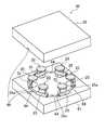
衝撃緩衝部材10は、例えば図3に示した金型装置50を用いて射出成形により製造される。金型装置50は、例えば略矩形状に形成されていて、いずれもキャビティ型の下側金型51および上側金型52からなる。金型装置50は、例えば上側金型52が下側金型51に対して上下可動するように構成されている。(Molding equipment)
The
下側金型51の上面側には、平面視で略円形状のキャビティ53が凹陥形成されている。また、上側金型52の下面側にも、下側金型51のキャビティ53と同じ大きさおよび形状となるキャビティ53が形成されている(図3参照)。下側金型51および上側金型52は、キャビティ53,53同士が互いに上下に対向するように重ね合わされている。そして、後述する第1収容部61,61,…、第2収容部62、および成形部64,64,…は、下側金型51および上側金型52が重ね合わされたときのキャビティ53,53
の一部として構成されている。On the upper surface side of the
Is configured as part of
金型装置50は、衝撃緩衝部材10の各管部25を収容可能な複数(図示例では3つ)の第1収容部61,61,…を備えている。各第1収容部61は、下側金型51および上側金型52が重ね合わされた状態で略円柱の空洞状に形成されていて、各管部25の外形に適合するように湾曲形成されている。第1収容部61,61,…は、キャビティ53の周方向において等間隔に配置されている。 The
金型装置50は、衝撃緩衝部材10の支持部材20を収容するための第2収容部62を備えている。第2収容部62は、支持部材20を収容可能な形状となるように形成されている。 The
金型装置50は、衝撃緩衝部材10の連結部材40を成形するための複数の成形部64,64,…を備えている。成形部64,64,…は、キャビティ53の周方向において等間隔に配置されている。具体的に、各成形部64は、第1収容部61,61同士の間に配置されている。 The
各成形部64は、下側金型51および上側金型52が重ね合わされた状態で略円柱の空洞状に形成されていて、連結部材40の外形に適合するように湾曲状に形成されている。また、各成形部64は、各第1収容部61に各管部25を収容した状態で各管部25の孔部25aと連通するように延びている。そして、キャビティ53内には、各成形部64と各管部25の孔部25aとが互いに連通した状態で閉塞状の経路が形成されている。 Each
金型装置50は、成形部64と連通するゲート部65を備えている。ゲート部65は、下側金型51および上側金型52が重ね合わされた状態で金型装置50の側面からキャビティ53,53内に向かって先細るように延びる略円錐形状に形成されている。 The
(衝撃緩衝部材の製造方法)
次に、図3〜図7を参照しながら衝撃緩衝部材10の製造方法を説明する。この製造方法は、主に(1)インサート工程および(2)成形工程を有している。なお、図4〜図6については、支持部材20および連結部材40を金型装置50の各要素と区別して示すために、支持部材20および連結部材40に対してドットによるハッチングを付している。(Method of manufacturing shock absorbing member)
Next, a manufacturing method of the
(1)インサート工程
インサート工程では、各管部25を各第1収容部61に収容しかつ支持部材20を第2収容部62に収容することにより、各成形部64と各管部25の孔部25aとを連通させる。具体的に、下側金型51を例えば図示しない設置台などに固定した状態で上側金型52を持ち上げて、金型装置50を上下に分離した状態とする(図3参照)。次に、各管部25および支持部材20の各々を、下側金型51の各第1収容部61および第2収容部62のそれぞれに収容する(図4参照)。この収容作業を終えた後、上側金型52を下側金型51に重ね合わせる(図5参照)。これにより、各成形部64および各管部25の孔部25aが互いに連通した状態となる。(1) Insert process In the insert process, each
(2)成形工程
次に、成形工程では、連結部材40を構成する熱可塑性樹脂材を金型装置50に射出(注入)して、管部25,25,…と連結部材40とを一体成形する。具体的に、上記熱可塑性樹脂材を、図示しない射出成形機により加熱溶融した後に金型装置50のゲート部65から各成形部64および各管部25に向けて射出する(図5参照)。このとき、上記熱可塑性樹脂材の成型温度を、連結部材40を構成する材料に適した温度(表1を参照)となるように適宜設定する。そして、上記熱可塑性樹脂材が各成形部64および各管部25の孔部25a内に充填された後に金型装置50に対して所定の冷却処理を行うことにより、管部25,25,…と連結部材40とが一体成形された状態となる。特に、この実施形態における成形工程では、連結部材40が各管部25の孔部25a内に挿通された状態で端部同士に継ぎ目がない閉塞状となるように管部25,25,…と連結部材40とを一体成形している。そして、上記冷却処理が終了した後、上側金型52を持ち上げて衝撃緩衝部材10を取り出す(図6および図7)。(2) Molding process Next, in the molding process, the thermoplastic resin material constituting the connecting
上記(1)および(2)の工程を経ることにより衝撃緩衝部材10が得られる。 The
[第1実施形態の作用効果]
以上のように、衝撃緩衝部材10の製造方法は、各管部25を各第1収容部61に収容することにより、各成形部64と各管部25とを連通させるインサート工程と、連結部材40を構成する熱可塑性樹脂材を、加熱溶融してゲート部65から各成形部64および各管部25に向けて注入することにより、複数の管部25,25,…と連結部材40とを一体成形する成形工程と、を備えている。この製造方法によれば、インサート工程を経ることにより金型装置50内で各成形部64と各管部25とを連通させることが容易となる。その結果、成形工程において、管部25,25,…および連結部材40の位置関係を金型装置50内で安定的に保ちながら精度よく一体成形することが可能となる。また、成形工程で管部25,25,…と連結部材40とを一体成形することにより、管部25,25,…と連結部材40とを別途組み立てる作業が不要になるとともに、連結部材40が管部25,25,…に対し接着剤で固着されていなくても連結部材40が管部25,25,…内から外れにくい構造を容易に得ることが可能となる。したがって、本発明の第1実施形態に係る衝撃緩衝部材10の製造方法では、堅牢な衝撃緩衝部材10を安定して容易に得ることができる。[Effects of First Embodiment]
As described above, the manufacturing method of the
また、インサート工程では、各管部25を各第1収容部61に収容しかつ支持部材20を第2収容部62に収容することにより、各成形部64と各管部25とを連通させている。これにより、支持部材20を備えた衝撃緩衝部材10を安定して容易に得ることができる。 Further, in the insert step, each
また、成形工程では、連結部材40が各管部25内に挿通された状態で端部同士に継ぎ目がない閉塞状となるように管部25,25,…と連結部材40とを一体成形している。すなわち、この実施形態における成形工程で得られた連結部材40は、各管部25と連通した状態で閉塞状の経路が形成されるように構成されている。このため、上下方向の外力Fにより連結部材40が弾性変形したとしても、連結部材40を管部25,25,…内から外れにくい堅牢な衝撃緩衝部材10を安定して容易に得ることができる。 In the molding step, the
また、支持部材20および管部25,25,…は、連結部材40を構成する熱可塑性樹脂材の成形温度よりも高い融点を有する材料からなる。これにより、成形工程において、支持部材20および管部25,25,…が溶融してしまうおそれがないため、衝撃緩衝部材10を安定して容易に得ることができる。 Further, the
また、支持部材20および管部25,25,…は、連結部材40を構成する熱可塑性樹脂材よりも高い剛性を有する材料からなる。これにより、衝撃緩衝性および反発性を有する衝撃緩衝部材10を安定して容易に得ることができる。 Further, the
[第2実施形態]
図8〜図13は、本発明の第2実施形態に係る衝撃緩衝部材10およびそれを製造するための金型装置50を示す。この実施形態では、第1実施形態と比較して、衝撃緩衝部材10および金型装置50の構成が一部異なっている。なお、この実施形態に係る衝撃緩衝部材10および金型装置50の他の構成は、第1実施形態に係る衝撃緩衝部材10および金型装置50の構成と同様である。このため、以下の説明では、図1〜図7と同じ部分について同じ符号を付し、その詳細な説明を省略する。[Second Embodiment]
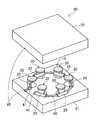
8 to 13 show an
図8に示すように、衝撃緩衝部材10は、その外周部が平面視で多角形の環状となるように形成されている。衝撃緩衝部材10は、複数(図示例では6つ)の支持部材20,20,…を備えている。支持部材20,20,…は、外周部11の周方向に沿って互いに間隔をあけて配置されている。 As shown in FIG. 8, the
各支持部材20において、底板部21と天板部22との上下間には、1つの壁部23が設けられている。壁部23は、底板部21および天板部22と一体に形成されている。壁部23は、側面視で各々の上下方向略中央部が外側方向に向かって突出するように湾曲形成されている。 In each
支持部材20は、1つの管部25を有している。管部25は、壁部23の上下方向略中央の位置に配置されている。管部25は、外周部11の周方向に沿って直線状に延びていて、壁部23の上下方向略中央の位置で壁部23と一体に形成されている。 The
連結部材40は、支持部材20,20同士の間に架け渡されていて、支持部材20,20同士を互いに連結している。具体的に、連結部材40は、隣り合う支持部材20,20同士の間で外周部11の周方向に沿うように多角形状に形成されている。また、連結部材40は、各支持部材20における管部25の孔部25a内に挿通された状態で端部同士に継ぎ目がないように閉塞状に一体形成されている。 The connecting
次に、図9に示すように、金型装置50の各第1収容部61は、下側金型51および上側金型52が重ね合わされた状態で略円柱の空洞状に形成されていて、各管部25の外形に適合するように直線状に形成されている。第1収容部61,61,…は、キャビティ53の周方向において等間隔に配置されている。また、図13にも示すように、各第1収容部61には、各管部25の両端部を保持可能な保持部66,66が設けられている。 Next, as shown in FIG. 9, each first accommodating
金型装置50は、衝撃緩衝部材10の支持部材20を収容するための複数(図示例では6つ)の第3収容部63,63,…を備えている。第3収容部63,63,…は、各成形部64を介して周方向に互いに間隔をあけて金型装置50のキャビティ53,53内に配置されている。各第3収容部63は、各支持部材20を収容可能な形状となるように形成されている。なお、この実施形態で示す金型装置50には、上記第1実施形態で示した第2収容部62が設けられていない。 The
各成形部64は、下側金型51および上側金型52が重ね合わされた状態で略円柱の空洞状に形成されていて、連結部材40の外形に適合するように直線状に形成されている。また、各成形部64は、各第1収容部61に各管部25を収容した状態で各管部25の孔部25aと連通するように延びている。そして、各成形部64および各管部25は、互いに連通した状態で閉塞状の経路が形成されるようになっている。 Each
次に、図9〜図13を参照しながら衝撃緩衝部材10の製造方法を説明する。この製造方法は、上記第1実施形態と同様に、(1)インサート工程および(2)成形工程を有している。なお、図10〜図12については、第1実施形態と同様に、支持部材20および連結部材40に対してドットによるハッチングを付している。 Next, a method for manufacturing the
(1)インサート工程
インサート工程では、各管部25を各第1収容部61に収容しかつ各支持部材20を各第3収容部63に収容することにより、各成形部64と各管部25とを連通させる。具体的には、下側金型51を固定した状態で上側金型52を持ち上げて、金型装置50を上下に分離した状態とする(図9参照)。次に、各管部25および各支持部材20の各々を、下側金型51の各第1収容部61および各第3収容部63のそれぞれに収容する(図11参照)。特に、各管部25を、その両端部が保持部66,66により適切に保持されるように位置合わせを行いながら各第1収容部61に収容する(図10参照)。この収容作業を終えた後、上側金型52を下側金型51に重ね合わせる(上記第1実施形態で示した図5を参照)。これにより、各成形部64および各管部25が互いに連通した状態となる。(1) Insert Step In the insert step, each
(2)成形工程
次に、成形工程では、上記第1実施形態と同様に、連結部材40を構成する熱可塑性樹脂材を、図示しない射出成形機により加熱溶融した後に金型装置50のゲート部65から各成形部64および各管部25に向けて射出する(図5参照)。そして、上記熱可塑性樹脂材が各成形部64および各管部25に充填された後に金型装置50に対して所定の冷却処理を行うことにより、管部25,25,…と連結部材40とが一体成形された状態となる。この実施形態でも、成形工程において、連結部材40が各管部25の孔部25a内に挿通された状態で端部同士に継ぎ目がない閉塞状となるように管部25,25,…と連結部材40とを一体成形している。そして、上記冷却処理が終了した後、上側金型52を持ち上げて衝撃緩衝部材10を取り出す(図12および図13参照)。このようにして、衝撃緩衝部材10が得られる。(2) Molding process Next, in the molding process, the thermoplastic resin material constituting the connecting
以上のように、この実施形態に係る衝撃緩衝部材10の製造方法では、インサート工程において、各管部25を各第1収容部61に収容しかつ各支持部材20を各第3収容部63に収容することにより、各成形部64と各管部25とを連通させている。これにより、複数の支持部材20,20,…を備えた衝撃緩衝部材10を安定して容易に得ることができる。 As described above, in the manufacturing method of the
また、インサート工程において、各管部25の両端部を保持部66,66に保持した状態で各管部25を各第1収容部61に収容することにより、各成形部64と各管部25とを連通させている。これにより、各管部25の両端部が保持部66,66により金型装置50内で安定することから、各成形部64と各管部25とを精度よく連通させることができる。 Further, in the insert step, each
[第3実施形態]
図14および図15は、本発明の第3実施形態に係る衝撃緩衝部材10およびそれを製造するための金型装置50を示す。この実施形態では、第2実施形態と比較して、衝撃緩衝部材10および金型装置50の構成が一部異なっている。なお、この実施形態に係る衝撃緩衝部材10および金型装置50の他の構成は、第2実施形態に係る衝撃緩衝部材10および金型装置50の構成と同様である。このため、以下の説明では、図8〜図13と同じ部分について同じ符号を付し、その詳細な説明を省略する。[Third Embodiment]
14 and 15 show an
この実施形態に係る衝撃緩衝部材10において、連結部材40は、その形状が上記第2実施形態で示した閉塞状の連結部材40と異なるように構成されている。具体的に、連結部材40は、上記第2実施形態で示した連結部材40の一部が途切れた非閉塞状となるように形成されている。図14および図15に示すように、連結部材40は、両端側に位置する管部25,25同士の間に亘って非閉塞状に延びている。 In the
連結部材40の各端部には、抜け止め部41が形成されている。抜け止め部41,41は、連結部材40の両端側に位置する管部25,25の外側に配置されている。具体的に、抜け止め部41,41は、各々が連結部材40の周方向において互いに間隔をあけて対向するように配置されている。各抜け止め部41は、各管部25における孔部25aの内径よりも大きい外径を有している。 A
図14および図15に示すように、各図中の左側に位置している抜け止め部41は略球状に形成されている一方、各図中の右側に位置している抜け止め部41は略円盤状に形成されている。なお、抜け止め部41,41は、上記形状に限られず、種々の形状にすることが可能である。 As shown in FIGS. 14 and 15, the retaining
図15に示すように、金型装置50は、抜け止め部用成形部67,67を備えている。抜け止め部用成形部67,67は、衝撃緩衝部材10の両端側に位置する管部25,25を収容する第1収容部61,61の外側に配設されている。図15の左側に位置している抜け止め部用成形部67は略球状に形成されている一方、右側に位置している抜け止め部用成形部67は略円盤状に形成されている。なお、この実施形態では、ゲート部65が右側の抜け止め部用成形部67と連通した状態となっている。 As shown in FIG. 15, the
そして、図14に示すように、衝撃緩衝部材10の製造方法における成形工程において、連結部材40を構成する熱可塑性樹脂材を抜け止め部用成形部67,67に向かって射出することにより、連結部材40の両端部に抜け止め部41,41を成形する。これにより、非閉塞状の連結部材40が衝撃緩衝部材10の両端側に位置する管部25,25から抜けにくい堅牢な衝撃緩衝部材10を容易に得ることができる。 Then, as shown in FIG. 14, in the molding step in the manufacturing method of the
[その他の実施形態]
上記各実施形態の金型装置50として、上側金型52が下側金型51に対して上下可動する形態のみを示したが、この形態に限られない。例えば、金型装置50は、下側金型51が上側金型52に対して上下可動するように構成されていてもよい。あるいは、上側金型52が下側金型51に対して前後方向または左右方向に可動するように構成されていてもよい。[Other Embodiments]
As the
また、上記各実施形態の金型装置50では、下側金型51および上側金型52において、キャビティ53,53が互いに同じ大きさおよび同じ形状となる形態を示したが、この形態に限られない。すなわち、下側金型51および上側金型52のいずれか一方のみにキャビティ53が形成されていてもよい。 In the
また、上記各実施形態として、金型装置50が1つのゲート部65を備える形態のみを示したが、この形態に限られず、ゲート部65を複数設けた形態としてもよい。 Moreover, although only the form with which the
また、上記各実施形態の製造方法として、射出成形により衝撃緩衝部材10を得る方法を示したが、この方法に限られない。例えば、金型と同形状の成形品が得られるポリウレタンの注型成形などにより衝撃緩衝部材10を製造してもよい。なお、注型成形により衝撃緩衝部材10を製造する場合において、発泡等により脱型後に明らかに膨張するような成形方法および材料は適していない。 Moreover, although the method of obtaining the
また、上記第1実施形態の金型装置50として、上記第2実施形態で示した保持部66,66が各第1収容部61に設けられていない形態を説明したが、この形態に限られない。すなわち、上記第1実施形態の金型装置50は、上記第2実施形態で示した保持部66,66が各第1収容部61に設けられた形態であってもよい。 Moreover, although the holding |
また、上記第2実施形態の衝撃緩衝部材10として、各支持部材20が1つの管部25を有する形態を示したが、この形態に限られない。例えば、衝撃緩衝部材10が複数の連結部材40,40,…を備える場合において、連結部材40,40,…の個数に対応するように複数の管部25,25,…を各支持部材20に設けてもよい。要は、上記第2実施形態の衝撃緩衝部材10として、各支持部材20が少なくとも1つの管部25を有する形態であってもよい。そして、各支持部材20が複数の管部25,25,…を有する衝撃緩衝部材10を製造する場合には、該管部25,25,…を収容可能な第1収容部61,61,…を金型装置50に適宜設ければよい。 Moreover, although each
また、上記第3実施形態の衝撃緩衝部材10として、上記第2実施形態で示した連結部材40を非閉塞状に形成した形態を示したが、この形態に限られない。例えば、上記第3実施形態における衝撃緩衝部材10の変形例として、上記第1実施形態で示した連結部材40を非閉塞状に形成した形態としてもよい。このような変形例の衝撃緩衝部材10を製造する場合には、上記第3実施形態と同様に、上記第1実施形態で示した金型装置50に抜け止め部用成形部67,67を設けるとともに、上記成形工程において、連結部材40を構成する熱可塑性樹脂材を抜け止め部用成形部67,67に向かって射出することにより、連結部材40の両端部に抜け止め部41,41を成形する。これにより、非閉塞状の連結部材40が衝撃緩衝部材10の両端側に位置する管部25,25から抜けにくい堅牢な衝撃緩衝部材10を容易に得ることができる。 Moreover, although the form which formed the
以上、本発明についての実施形態を説明したが、本発明は上述の実施形態のみに限定されず、発明の範囲内で種々の変更が可能である。 As mentioned above, although embodiment about this invention was described, this invention is not limited only to the above-mentioned embodiment, A various change is possible within the scope of the invention.
本発明は、例えばランニング、球技等の各種競技におけるスポーツ用シューズ、日常使用のスニーカー、リハビリ用シューズに適用される衝撃緩衝部材の製造方法として産業上の利用が可能である。 INDUSTRIAL APPLICABILITY The present invention can be industrially used as a manufacturing method of an impact buffer member applied to sports shoes for various sports such as running and ball games, daily sneakers, and rehabilitation shoes.
S:シューズ
1:ソール
10:衝撃緩衝部材
20:支持部材
25:管部
40:連結部材
41:抜け止め部
50:金型装置
61:第1収容部
62:第2収容部
63:第3収容部
64:成形部
65:ゲート部
66:保持部
67:抜け止め部用成形部
S: Shoes 1: Sole 10: Shock absorbing member 20: Support member 25: Pipe portion 40: Connecting member 41: Retaining portion 50: Mold device 61: First housing portion 62: Second housing portion 63: Third housing Part 64: Molding part 65: Gate part 66: Holding part 67: Molding part for retaining part
Claims (10)
Translated fromJapanese前記金型装置は、
前記複数の管部を互いに間隔をあけて配置した状態で収容可能な複数の第1収容部と、
前記第1収容部同士の間に形成され、前記各第1収容部に前記各管部を収容した状態で該各管部と連通するように延びる複数の成形部と、
前記複数の成形部と連通するゲート部と、を備え、
前記衝撃緩衝部材の製造方法は、
前記各管部を前記各第1収容部に収容することにより、前記各成形部と前記各管部とを連通させるインサート工程と、
前記連結部材を構成する熱可塑性樹脂材を、加熱溶融して前記ゲート部から前記各成形部および前記各管部に向けて注入することにより、前記複数の管部と前記連結部材とを一体成形する成形工程と、を備える、衝撃緩衝部材の製造方法。At least one supporting member, a plurality of pipe parts arranged at intervals, and spanned between the pipe parts in a state of being inserted into the pipe parts and connected to each other. A shock absorbing member manufacturing method for manufacturing a shock absorbing member of a shoe sole provided with a connecting member using a mold device,
The mold apparatus is
A plurality of first accommodating portions that can be accommodated in a state in which the plurality of pipe portions are arranged at intervals from each other;
A plurality of molded portions formed between the first housing portions and extending so as to communicate with the tube portions in a state where the tube portions are housed in the first housing portions;
A gate portion communicating with the plurality of molding portions,
The manufacturing method of the shock absorbing member is:
An insert step of communicating each molded part and each pipe part by accommodating each pipe part in each first accommodating part;
The plurality of tube portions and the connection member are integrally formed by heating and melting the thermoplastic resin material constituting the connection member from the gate portion toward the forming portions and the tube portions. A method for manufacturing the impact buffering member.
前記支持部材は、1つ設けられており、
前記支持部材は、前記複数の管部を周方向に互いに間隔をあけて配置した状態で該複数の管部と一体形成されており、
前記金型装置は、前記支持部材を収容するための第2収容部をさらに備え、
前記インサート工程において、前記各管部を前記各第1収容部に収容しかつ前記支持部材を前記第2収容部に収容することにより、前記各成形部と前記各管部とを連通させる、衝撃緩衝部材の製造方法。In the manufacturing method of the shock absorbing member according to claim 1,
One supporting member is provided ,
The support member is integrally formed with the plurality of tube portions in a state where the plurality of tube portions are arranged at intervals in the circumferential direction,
The mold apparatus further includes a second accommodating portion for accommodating the support member,
In the insert step, an impact that causes the molded portions and the pipe portions to communicate with each other by housing the tube portions in the first housing portions and housing the support member in the second housing portion. The manufacturing method of a buffer member.
前記支持部材は、複数設けられており、
前記各支持部材は、少なくとも1つの前記管部と一体形成されており、
前記金型装置は、前記複数の支持部材を収容するための複数の第3収容部をさらに備え、
前記複数の第3収容部は、前記各成形部を介して周方向に互いに間隔をあけて前記金型装置内に配置されており、
前記インサート工程において、前記各管部を前記各第1収容部に収容しかつ前記各支持部材を前記各第3収容部に収容することにより、前記各成形部と前記各管部とを連通させる、衝撃緩衝部材の製造方法。In the manufacturing method of the shock absorbing member according to claim 1,
A plurality of the support members are provided ,
Each of the support members is integrally formed with at least one of the pipe portions,
The mold apparatus further includes a plurality of third accommodating portions for accommodating the plurality of support members,
The plurality of third accommodating portions are arranged in the mold apparatus at intervals in the circumferential direction via the molding portions,
In the insert step, the molded parts and the pipe parts are communicated with each other by accommodating the pipe parts in the first accommodating parts and accommodating the support members in the third accommodating parts. The manufacturing method of an impact buffer member.
前記各第1収容部には、前記各管部の両端部を保持可能な保持部が設けられており、
前記インサート工程において、前記各管部の両端部を前記保持部に保持した状態で前記各管部を前記各第1収容部に収容することにより、前記各成形部と前記各管部とを連通させる、衝撃緩衝部材の製造方法。In the manufacturing method of the shock absorbing member according to any one of claims 1 to 3,
Each of the first accommodating portions is provided with a holding portion capable of holding both end portions of each of the tube portions,
In the insert step, the tube portions are accommodated in the first accommodating portions in a state where both end portions of the tube portions are retained by the retaining portions, whereby the molding portions and the tube portions are communicated with each other. A method for manufacturing an impact buffering member.
前記複数の成形部は、前記各管部と連通した状態で閉塞状の経路が形成されるように構成されており、
前記成形工程において、前記連結部材が前記各管部内に挿通された状態で端部同士に継ぎ目がない閉塞状となるように前記複数の管部と前記連結部材とを一体成形する、衝撃緩衝部材の製造方法。In the manufacturing method of the shock absorbing member according to any one of claims 1 to 4,
The plurality of molded portions are configured such that a closed path is formed in communication with the pipe portions,
In the molding step, the shock absorbing member integrally molds the plurality of pipe portions and the connecting member so that the connecting members are inserted into the pipe portions so that the end portions are seamlessly closed. Manufacturing method.
前記連結部材は、前記衝撃緩衝部材の両端側に位置する前記管部同士の間に亘って非閉塞状に延びており、
前記連結部材の両端には、前記衝撃緩衝部材の両端側に位置する前記管部の外側に配置され、前記各管部の内径よりも大きい外径を有する抜け止め部が形成されており、
前記金型装置は、前記衝撃緩衝部材の両端側に位置する前記管部を収容する前記第1収容部の外側に設けられた抜け止め部用成形部をさらに備え、
前記成形工程において、前記熱可塑性樹脂材を前記抜け止め部用成形部に向かって注入することにより前記抜け止め部を成形する、衝撃緩衝部材の製造方法。In the manufacturing method of the shock absorbing member according to any one of claims 1 to 4,
The connecting member extends in a non-blocking manner between the pipe portions located on both end sides of the shock absorbing member,
At both ends of the connecting member, arranged on the outer side of the tube portion located on both ends of the shock absorbing member, a retaining portion having an outer diameter larger than the inner diameter of each tube portion is formed,
The mold apparatus further includes a retaining portion molding portion provided outside the first housing portion that houses the pipe portion positioned on both ends of the shock absorbing member,
The method for producing an impact buffering member, wherein, in the molding step, the retaining portion is molded by injecting the thermoplastic resin material toward the retaining portion molding portion.
前記複数の管部は、前記熱可塑性樹脂材よりも高い剛性を有する材料からなる、衝撃緩衝部材の製造方法。In the manufacturing method of the shock absorbing member according to any one of claims 1 to 6,
The manufacturing method of an impact buffering member, wherein the plurality of pipe portions are made of a material having higher rigidity than the thermoplastic resin material.
前記複数の管部は、前記熱可塑性樹脂材の成形温度よりも高い融点を有する材料からなる、衝撃緩衝部材の製造方法。In the manufacturing method of the shock absorbing member according to any one of claims 1 to 6,
The method for manufacturing an impact buffering member, wherein the plurality of pipe portions are made of a material having a melting point higher than a molding temperature of the thermoplastic resin material.
前記支持部材は、前記熱可塑性樹脂材の成形温度よりも高い融点を有する材料からなる、衝撃緩衝部材の製造方法。In the manufacturing method of the shock absorbing member according to claim 2 or 3,
The method for manufacturing an impact buffering member, wherein the support member is made of a material having a melting point higher than a molding temperature of the thermoplastic resin material.
前記支持部材は、前記熱可塑性樹脂材よりも高い剛性を有する材料からなる、衝撃緩衝部材の製造方法。In the manufacturing method of the shock absorbing member according to claim 2 or 3,
The method for manufacturing an impact buffering member, wherein the support member is made of a material having higher rigidity than the thermoplastic resin material.
Priority Applications (3)
| Application Number | Priority Date | Filing Date | Title |
|---|---|---|---|
| JP2017243130AJP6611372B2 (en) | 2017-12-19 | 2017-12-19 | Method for manufacturing shock absorbing member |
| DE102018132041.8ADE102018132041B4 (en) | 2017-12-19 | 2018-12-13 | Method of manufacturing a shock absorber element |
| US16/224,085US10618208B2 (en) | 2017-12-19 | 2018-12-18 | Method for producing shock absorbing member |
Applications Claiming Priority (1)
| Application Number | Priority Date | Filing Date | Title |
|---|---|---|---|
| JP2017243130AJP6611372B2 (en) | 2017-12-19 | 2017-12-19 | Method for manufacturing shock absorbing member |
Publications (2)
| Publication Number | Publication Date |
|---|---|
| JP2019107833A JP2019107833A (en) | 2019-07-04 |
| JP6611372B2true JP6611372B2 (en) | 2019-11-27 |
Family
ID=66674583
Family Applications (1)
| Application Number | Title | Priority Date | Filing Date |
|---|---|---|---|
| JP2017243130AActiveJP6611372B2 (en) | 2017-12-19 | 2017-12-19 | Method for manufacturing shock absorbing member |
Country Status (3)
| Country | Link |
|---|---|
| US (1) | US10618208B2 (en) |
| JP (1) | JP6611372B2 (en) |
| DE (1) | DE102018132041B4 (en) |
Families Citing this family (4)
| Publication number | Priority date | Publication date | Assignee | Title |
|---|---|---|---|---|
| US10687583B2 (en)* | 2017-09-27 | 2020-06-23 | Mizuno Corporation | Shock absorbing member for sole of shoe and shoe including shock absorbing member |
| KR102345003B1 (en)* | 2020-05-27 | 2021-12-29 | 데상트코리아 주식회사 | Midsole assembly for footwear and footwear including the same |
| US11965573B2 (en)* | 2020-08-10 | 2024-04-23 | Accelerated Research LLC | Device for attenuating energy |
| CN114801034B (en)* | 2022-04-13 | 2023-01-24 | 沭阳东鸿鞋业有限公司 | Injection molding method for producing high-elasticity plastic slippers |
Family Cites Families (11)
| Publication number | Priority date | Publication date | Assignee | Title |
|---|---|---|---|---|
| US4492374A (en)* | 1981-04-21 | 1985-01-08 | David Lekhtman | Sporting and exercising spring shoe |
| JPH0779724B2 (en)* | 1989-12-26 | 1995-08-30 | 義郎 中松 | Sho shoes |
| TW351926U (en)* | 1998-02-27 | 1999-02-01 | Yan-Yu Li | Bounce spots shoes |
| US6607684B1 (en)* | 2000-09-19 | 2003-08-19 | C. J. Associates, Ltd. | Method of making a jointed linkage support system |
| DE10234913B4 (en)* | 2002-07-31 | 2005-11-10 | Adidas International Marketing B.V. | sole |
| US7708923B1 (en)* | 2004-02-19 | 2010-05-04 | Saint-Gobain Performance Plastics Corporation | Process of molding a coupling for interconnecting tubes |
| US7314125B2 (en)* | 2004-09-27 | 2008-01-01 | Nike, Inc. | Impact attenuating and spring elements and products containing such elements |
| US7730635B2 (en)* | 2004-09-27 | 2010-06-08 | Nike, Inc. | Impact-attenuation members and products containing such members |
| CA2633067C (en)* | 2007-09-06 | 2018-05-29 | Powerdisk Development Ltd. | Energy storage and return spring |
| US20090126224A1 (en)* | 2007-11-19 | 2009-05-21 | Greene Pamela S | Differential-stiffness impact-attenuation members and products including them |
| DE202012101767U1 (en)* | 2012-05-14 | 2013-08-19 | Diemer & Dr. Jaspert GbR (vertretungsberechtigter Gesellschafter: Herrn Dr. Bodo F. Jaspert, 85630 Grasbrunn) | spring element |
- 2017
- 2017-12-19JPJP2017243130Apatent/JP6611372B2/enactiveActive
- 2018
- 2018-12-13DEDE102018132041.8Apatent/DE102018132041B4/enactiveActive
- 2018-12-18USUS16/224,085patent/US10618208B2/enactiveActive
Also Published As
| Publication number | Publication date |
|---|---|
| DE102018132041A1 (en) | 2019-06-19 |
| US10618208B2 (en) | 2020-04-14 |
| US20190184613A1 (en) | 2019-06-20 |
| DE102018132041B4 (en) | 2020-03-26 |
| JP2019107833A (en) | 2019-07-04 |
Similar Documents
| Publication | Publication Date | Title |
|---|---|---|
| JP6611372B2 (en) | Method for manufacturing shock absorbing member | |
| JP6934561B2 (en) | How to make shoes | |
| JP7114743B2 (en) | Method for manufacturing soles for shoes, especially athletic shoes | |
| JP2019115823A (en) | Sole for shoe and shoe | |
| US10016919B2 (en) | Method of making an article of footwear with a segmented plate | |
| US9743711B2 (en) | Sole assembly with plural portions that cooperatively define chamber | |
| JP7413457B2 (en) | Shock-absorbing member for shoe soles and shoes equipped with the same | |
| US9955752B2 (en) | Sole structure for a baseball spiked shoe | |
| JP2019122544A (en) | Sole structure and shoe using the same | |
| US12127625B2 (en) | Article of footwear | |
| KR101046741B1 (en) | Shoe airbag and manufacturing method | |
| CN111741692A (en) | Sole for shoes | |
| US10736375B2 (en) | Shoe sole with zones filled with multiple foaming material and an interchangeable compact MagLev module | |
| CN113841968B (en) | Sole component, molded assembly, and method of manufacturing for an article of footwear | |
| JP7115860B2 (en) | Shoe sole shock absorbing member and shoe provided with the same | |
| KR101743857B1 (en) | Article of footwear formed from two preforms and method and mold for manufacturing same | |
| KR101648214B1 (en) | Method of producing functional insole | |
| KR100972609B1 (en) | Assistance shoes heel and manufacturing methods | |
| KR101391357B1 (en) | Functionality insole and producting method thereof | |
| KR101610261B1 (en) | Sole with shock absorbing method for manufacturing | |
| CN114340435B (en) | Shoe sole with support member | |
| JP2008528074A (en) | Shoes, especially sports shoes | |
| KR101074908B1 (en) | shoes | |
| KR101445267B1 (en) | Article of footwear | |
| KR101638396B1 (en) | Length universal shoe sole and manufacturing method thereof |
Legal Events
| Date | Code | Title | Description |
|---|---|---|---|
| A621 | Written request for application examination | Free format text:JAPANESE INTERMEDIATE CODE: A621 Effective date:20180910 | |
| A977 | Report on retrieval | Free format text:JAPANESE INTERMEDIATE CODE: A971007 Effective date:20190802 | |
| A131 | Notification of reasons for refusal | Free format text:JAPANESE INTERMEDIATE CODE: A131 Effective date:20190806 | |
| A521 | Request for written amendment filed | Free format text:JAPANESE INTERMEDIATE CODE: A523 Effective date:20191002 | |
| TRDD | Decision of grant or rejection written | ||
| A01 | Written decision to grant a patent or to grant a registration (utility model) | Free format text:JAPANESE INTERMEDIATE CODE: A01 Effective date:20191023 | |
| A61 | First payment of annual fees (during grant procedure) | Free format text:JAPANESE INTERMEDIATE CODE: A61 Effective date:20191028 | |
| R150 | Certificate of patent or registration of utility model | Ref document number:6611372 Country of ref document:JP Free format text:JAPANESE INTERMEDIATE CODE: R150 | |
| R250 | Receipt of annual fees | Free format text:JAPANESE INTERMEDIATE CODE: R250 | |
| R250 | Receipt of annual fees | Free format text:JAPANESE INTERMEDIATE CODE: R250 |