JP6607213B2 - Shift range control device - Google Patents
Shift range control deviceDownload PDFInfo
- Publication number
- JP6607213B2 JP6607213B2JP2017030961AJP2017030961AJP6607213B2JP 6607213 B2JP6607213 B2JP 6607213B2JP 2017030961 AJP2017030961 AJP 2017030961AJP 2017030961 AJP2017030961 AJP 2017030961AJP 6607213 B2JP6607213 B2JP 6607213B2
- Authority
- JP
- Japan
- Prior art keywords
- motor
- angle
- value
- output shaft
- rotation
- Prior art date
- Legal status (The legal status is an assumption and is not a legal conclusion. Google has not performed a legal analysis and makes no representation as to the accuracy of the status listed.)
- Active
Links
Images


Classifications
- H—ELECTRICITY
- H02—GENERATION; CONVERSION OR DISTRIBUTION OF ELECTRIC POWER
- H02P—CONTROL OR REGULATION OF ELECTRIC MOTORS, ELECTRIC GENERATORS OR DYNAMO-ELECTRIC CONVERTERS; CONTROLLING TRANSFORMERS, REACTORS OR CHOKE COILS
- H02P6/00—Arrangements for controlling synchronous motors or other dynamo-electric motors using electronic commutation dependent on the rotor position; Electronic commutators therefor
- H02P6/14—Electronic commutators
- H02P6/15—Controlling commutation time
- F—MECHANICAL ENGINEERING; LIGHTING; HEATING; WEAPONS; BLASTING
- F16—ENGINEERING ELEMENTS AND UNITS; GENERAL MEASURES FOR PRODUCING AND MAINTAINING EFFECTIVE FUNCTIONING OF MACHINES OR INSTALLATIONS; THERMAL INSULATION IN GENERAL
- F16H—GEARING
- F16H61/00—Control functions within control units of change-speed- or reversing-gearings for conveying rotary motion ; Control of exclusively fluid gearing, friction gearing, gearings with endless flexible members or other particular types of gearing
- F16H61/26—Generation or transmission of movements for final actuating mechanisms
- F16H61/28—Generation or transmission of movements for final actuating mechanisms with at least one movement of the final actuating mechanism being caused by a non-mechanical force, e.g. power-assisted
- F16H61/32—Electric motors , actuators or related electrical control means therefor
- F16H2061/326—Actuators for range selection, i.e. actuators for controlling the range selector or the manual range valve in the transmission
- F—MECHANICAL ENGINEERING; LIGHTING; HEATING; WEAPONS; BLASTING
- F16—ENGINEERING ELEMENTS AND UNITS; GENERAL MEASURES FOR PRODUCING AND MAINTAINING EFFECTIVE FUNCTIONING OF MACHINES OR INSTALLATIONS; THERMAL INSULATION IN GENERAL
- F16H—GEARING
- F16H59/00—Control inputs to control units of change-speed- or reversing-gearings for conveying rotary motion
- F16H59/02—Selector apparatus
- F16H59/08—Range selector apparatus
- F—MECHANICAL ENGINEERING; LIGHTING; HEATING; WEAPONS; BLASTING
- F16—ENGINEERING ELEMENTS AND UNITS; GENERAL MEASURES FOR PRODUCING AND MAINTAINING EFFECTIVE FUNCTIONING OF MACHINES OR INSTALLATIONS; THERMAL INSULATION IN GENERAL
- F16H—GEARING
- F16H63/00—Control outputs from the control unit to change-speed- or reversing-gearings for conveying rotary motion or to other devices than the final output mechanism
- F16H63/02—Final output mechanisms therefor; Actuating means for the final output mechanisms
- F16H63/30—Constructional features of the final output mechanisms
- F16H63/34—Locking or disabling mechanisms
- F16H63/3416—Parking lock mechanisms or brakes in the transmission
- F16H63/3425—Parking lock mechanisms or brakes in the transmission characterised by pawls or wheels
Landscapes
- Engineering & Computer Science (AREA)
- General Engineering & Computer Science (AREA)
- Mechanical Engineering (AREA)
- Power Engineering (AREA)
- Gear-Shifting Mechanisms (AREA)
- Control Of Motors That Do Not Use Commutators (AREA)
- Control Of Ac Motors In General (AREA)
Description
Translated fromJapanese本発明は、シフトレンジ制御装置に関する。 The present invention relates to a shift range control device.
従来、レンジ切換機構の駆動源となるモータを制御するモータ制御装置が知られている。例えば特許文献1では、2系統のF/B制御系を有し、第1のF/B制御系において、出力軸センサの検出出力軸回転角と目標出力軸回転角との偏差を用い、目標モータ回転角を回転伝達系の遊び量に応じて補正している。 Conventionally, a motor control device that controls a motor that is a drive source of a range switching mechanism is known. For example,
特許文献1のように回転伝達系の遊び量に応じた目標モータ回転角の補正を行う場合、出力軸センサには、高い検出精度が要求される。また、出力軸センサの検出値に外乱等の影響によりノイズが生じた場合、誤った補正が行われる虞がある。
本発明は、上述の課題に鑑みてなされたものであり、その目的は、精度よくシフトレンジを切り替え可能であるシフトレンジ制御装置を提供することにある。When the target motor rotation angle is corrected according to the play amount of the rotation transmission system as in
The present invention has been made in view of the above-described problems, and an object thereof is to provide a shift range control device capable of switching the shift range with high accuracy.
本発明のシフトレンジ制御装置は、モータ(10)の回転軸であるモータ軸(105)とモータの回転が伝達される出力軸(15)との間に遊びが存在するシフトレンジ切替システム(1)において、モータの駆動を制御することでシフトレンジを切り替えるものである。シフトレンジ制御装置は、空走判定部(521)と、目標値設定部(525)と、を備える。 The shift range control device of the present invention includes a shift range switching system (1) in which there is play between a motor shaft (105) that is a rotation shaft of a motor (10) and an output shaft (15) to which the rotation of the motor is transmitted. ), The shift range is switched by controlling the driving of the motor. The shift range control device includes an idling determination unit (521) and a target value setting unit (525).
空走判定部は、モータの回転を検出するモータ回転角センサ(13)の検出値に基づく値であるモータ角度、および、出力軸の回転を検出する出力軸センサ(16)の検出値に基づく値である出力軸角度に基づき、遊びの範囲内にてモータが回転している空走状態の終了を判定する。
目標値設定部は、空走終了時におけるモータ角度に応じた値である角度補正値を用い、モータの駆動制御に係るモータ角度目標値を設定する。
第1の態様では、空走判定部は、モータ角度の単位時間あたりの変化量であるモータ角度変化量と、出力軸角度の単位時間あたりの変化量である出力軸角度変化量とが一致し、かつ、モータ角度変化量および出力軸角度変化量が共に回転判定閾値以上である場合、空走状態が終了したと判定する。
第2の態様では、空走判定部は、モータ角度と出力軸角度との差分値である角度差分値が差分判定閾値より大きく、かつ、角度差分値の単位時間あたりの変化量が0となったとき、空走状態が終了したと判定する。
第3の態様では、目標値設定部は、モータ角度の単位時間あたりの変化量であるモータ角度変化量と、出力軸角度の単位時間あたりの変化量である出力軸角度変化量との差分値がピーク値となったときのモータ角度を、空走終了時におけるモータ角度とみなし、当該モータ角度を角度補正値として、モータ角度目標値を設定する。
第4の態様では、空走判定部は、モータ角度および出力軸角度に基づき、空走状態である空走区間、および、モータ軸と出力軸とが一体となって回転している一体回転区間を設定し、空走区間におけるモータ角度の単位時間あたりの変化量であるモータ角度変化量の経時変化を表す近似線である第1近似線、および、一体回転区間におけるモータ角度変化量の経時変化を表す近似線である第2近似線を導出し、第1近似線と第2近似線との交点となるタイミングにて、空走状態が終了したとみなす。
第5の態様では、空走判定部は、モータ角度および出力軸角度に基づき、空走状態である空走区間、および、モータ軸と出力軸とが一体となって回転している一体回転区間を設定し、空走区間におけるモータ角度と出力軸角度との差分値である角度差分値の経時変化を表す近似線である第1近似線、および、一体回転区間における角度差分値の経時変化を表す近似線である第2近似線を導出し、第1近似線と第2近似線との交点となるタイミングにて、空走状態が終了したとみなす。
第6の態様では、空走判定部は、モータ角度および出力軸角度に基づき、空走状態である空走区間、および、モータ軸と出力軸とが一体となって回転している一体回転区間を設定し、空走区間における出力軸角度の経時変化を表す近似線である第1近似線、および、一体回転区間における出力軸角度の経時変化を表す近似線である第2近似線を導出し、第1近似線と第2近似線との交点となるタイミングにて、空走状態が終了したとみなす。The idle running determination unit is based on the motor angle that is a value based on the detection value of the motor rotation angle sensor (13) that detects the rotation of the motor and the detection value of the output shaft sensor (16) that detects the rotation of the output shaft. Based on the output shaft angle as a value, the end of the idle running state in which the motor is rotating within the range of play is determined.
The target value setting unit sets a motor angle target value related to motor drive control using an angle correction value that is a value corresponding to the motor angle at the end of idling.
In the first aspect, the idling determination unit matches the motor angle change amount that is the change amount per unit time of the motor angle with the output shaft angle change amount that is the change amount per unit time of the output shaft angle. When the motor angle change amount and the output shaft angle change amount are both equal to or greater than the rotation determination threshold value, it is determined that the idle running state has ended.
In the second aspect, the idling determination unit has an angle difference value, which is a difference value between the motor angle and the output shaft angle, larger than the difference determination threshold value, and the amount of change per unit time of the angle difference value is zero. It is determined that the free running state has ended.
In the third aspect, the target value setting unit is a difference value between a motor angle change amount that is a change amount per unit time of the motor angle and an output shaft angle change amount that is a change amount per unit time of the output shaft angle. Is regarded as the motor angle at the end of idling, and the motor angle target value is set with the motor angle as an angle correction value.
In the fourth aspect, the idling determination unit is based on the motor angle and the output shaft angle. The idling section is in the idling state, and the integral rotation section in which the motor shaft and the output shaft are rotated together. , And a first approximate line that is an approximate line representing a change over time of the motor angle change amount that is a change amount per unit time of the motor angle in the idle running section, and a change over time in the motor angle change amount in the integral rotation section A second approximate line, which is an approximate line representing the above, is derived, and it is considered that the idling state has ended at the timing of the intersection of the first approximate line and the second approximate line.
In the fifth aspect, the idling determination unit is based on the motor angle and the output shaft angle. The idling section is in an idling state, and the integral rotation section in which the motor shaft and the output shaft are rotated together. The first approximate line, which is an approximate line representing the change over time of the angle difference value that is the difference value between the motor angle and the output shaft angle in the idle running section, and the change over time in the angle difference value in the integral rotation section A second approximate line, which is an approximate line to be expressed, is derived, and it is considered that the idling state has ended at the timing of the intersection of the first approximate line and the second approximate line.
In the sixth aspect, the idling determination unit is based on the motor angle and the output shaft angle. The idling section is in an idling state, and the integral rotation section in which the motor shaft and the output shaft rotate together. And a first approximate line that is an approximate line that represents a change with time in the output shaft angle in the idling section and a second approximate line that is an approximate line that represents a change with time in the output shaft angle in the integral rotation section. The idle running state is considered to be completed at the timing of the intersection of the first approximate line and the second approximate line.
本発明では、モータ角度および出力軸角度を用いて空走状態の終了を判定し、空走終了時のモータ角度に基づいて、モータ角度目標値を設定している。これにより、遊び量の学習処理を行うことなく、モータ角度目標値を適切に設定することができる。また、モータ角度および出力軸角度の2つの異なる種類の検出値を空走終了判定に用いているので、例えば検出値として出力軸角度のみを用いて判定する場合と比較し、検出精度要求を緩和可能であるとともに、外乱ノイズ等の影響によりモータ角度目標値が誤った値に設定されるのを防ぐことができる。 In the present invention, the end of the idling state is determined using the motor angle and the output shaft angle, and the motor angle target value is set based on the motor angle at the end of idling. Thus, the motor angle target value can be appropriately set without performing the play amount learning process. In addition, since two different types of detection values of motor angle and output shaft angle are used for the idle running end determination, the detection accuracy requirement is relaxed compared with the case where determination is made using only the output shaft angle as the detection value, for example. It is possible to prevent the motor angle target value from being set to an incorrect value due to the influence of disturbance noise or the like.
シフトレンジ制御装置を図面に基づいて説明する。以下、複数の実施形態において、実質的に同一の構成には同一の符号を付して説明を省略する。
(第1実施形態)
第1実施形態によるシフトレンジ制御装置を図1〜図7に示す。
図1および図2に示すように、シフトレンジ切替システムとしてのシフトバイワイヤシステム1は、モータ10、シフトレンジ切替機構20、パーキングロック機構30、および、シフトレンジ制御装置40等を備える。
モータ10は、図示しない車両に搭載されるバッテリ45(図3参照。)から電力が供給されることで回転し、シフトレンジ切替機構20の駆動源として機能する。モータ10は、フィードバック制御により電流の大きさを変更可能であって、かつ、相ごとに指令を変更可能なものが用いられる。本実施形態のモータ10は、永久磁石式のDCブラシレスモータである。図3に示すように、モータ10は、2組の巻線組11、12を有する。第1巻線組11は、U1コイル111、V1コイル112、および、W1コイル113を有する。第2巻線組12は、U2コイル121、V2コイル122、および、W2コイル123を有する。The shift range control device will be described with reference to the drawings. Hereinafter, in a plurality of embodiments, the same numerals are given to the substantially same composition, and explanation is omitted.
(First embodiment)
A shift range control apparatus according to a first embodiment is shown in FIGS.
As shown in FIGS. 1 and 2, the shift-by-
The
図2に示すように、モータ回転角センサとしてのエンコーダ13は、モータ10の図示しないロータの回転位置を検出する。エンコーダ13は、例えば磁気式のロータリーエンコーダであって、ロータと一体に回転する磁石と、磁気検出用のホールIC等により構成される。エンコーダ13は、ロータの回転に同期して、所定角度ごとにA相およびB相のパルス信号を出力する。
減速機14は、モータ10のモータ軸105(図5参照。)と出力軸15との間に設けられ、モータ10の回転を減速して出力軸15に出力する。これにより、モータ10の回転がシフトレンジ切替機構20に伝達される。出力軸15には、出力軸15の角度である出力軸角度θsを検出する出力軸センサ16が設けられる。出力軸センサ16は、出力軸15の回転量に応じて、出力が連続的に変化するものである。本実施形態の出力軸センサ16は、出力軸15の回転量に応じて、出力がリニアに変化するポテンショメータである。As shown in FIG. 2, the
The
図1に示すように、シフトレンジ切替機構20は、ディテントプレート21、および、ディテントスプリング25等を有し、減速機14から出力された回転駆動力を、マニュアルバルブ28、および、パーキングロック機構30へ伝達する。
ディテントプレート21は、出力軸15に固定され、モータ10により駆動される。本実施形態では、ディテントプレート21がディテントスプリング25の基部から離れる方向を正回転方向、基部に近づく方向を逆回転方向とする。As shown in FIG. 1, the shift
The
ディテントプレート21には、出力軸15と平行に突出するピン24が設けられる。ピン24は、マニュアルバルブ28と接続される。ディテントプレート21がモータ10によって駆動されることで、マニュアルバルブ28は軸方向に往復移動する。すなわち、シフトレンジ切替機構20は、モータ10の回転運動を直線運動に変換してマニュアルバルブ28に伝達する。マニュアルバルブ28は、バルブボディ29に設けられる。マニュアルバルブ28が軸方向に往復移動することで、図示しない油圧クラッチへの油圧供給路が切り替えられ、油圧クラッチの係合状態が切り替わることでシフトレンジが変更される。
ディテントプレート21のディテントスプリング25側には、マニュアルバルブ28を各レンジに対応する位置に保持するための4つの凹部22が設けられる。凹部22は、ディテントスプリング25の基部側から、D、N、R、Pの各レンジに対応している。The
On the
ディテントスプリング25は、弾性変形可能な板状部材であり、先端にディテントローラ26が設けられる。ディテントローラ26は、凹部22のいずれかに嵌まり込む。
ディテントスプリング25は、ディテントローラ26をディテントプレート21の回動中心側に付勢する。ディテントプレート21に所定以上の回転力が加わると、ディテントスプリング25が弾性変形し、ディテントローラ26が凹部22を移動する。ディテントローラ26が凹部22のいずれかに嵌まり込むことで、ディテントプレート21の揺動が規制され、マニュアルバルブ28の軸方向位置、および、パーキングロック機構30の状態が決定され、自動変速機5のシフトレンジが固定される。The
The
パーキングロック機構30は、パーキングロッド31、円錐体32、パーキングロックポール33、軸部34、および、パーキングギア35を有する。
パーキングロッド31は、略L字形状に形成され、一端311側がディテントプレート21に固定される。パーキングロッド31の他端312側には、円錐体32が設けられる。円錐体32は、他端312側にいくほど縮径するように形成される。ディテントプレート21が逆回転方向に揺動すると、円錐体32が矢印Pの方向に移動する。The
The
パーキングロックポール33は、円錐体32の円錐面と当接し、軸部34を中心に揺動可能に設けられる、パーキングロックポール33のパーキングギア35側には、パーキングギア35と噛み合い可能な凸部331が設けられる。ディテントプレート21が逆回転方向に回転し、円錐体32が矢印P方向に移動すると、パーキングロックポール33が押し上げられ、凸部331とパーキングギア35とが噛み合う。一方、ディテントプレート21が正回転方向に回転し、円錐体32が矢印notP方向に移動すると、凸部331とパーキングギア35との噛み合いが解除される。 The
パーキングギア35は、図示しない車軸に設けられ、パーキングロックポール33の凸部331と噛み合い可能に設けられる。パーキングギア35と凸部331とが噛み合うと、車軸の回転が規制される。シフトレンジがP以外のレンジであるnotPレンジのとき、パーキングギア35はパーキングロックポール33によりロックされず、車軸の回転は、パーキングロック機構30により妨げられない。また、シフトレンジがPレンジのとき、パーキングギア35はパーキングロックポール33によってロックされ、車軸の回転が規制される。 The
図2および図3に示すように、シフトレンジ制御装置40は、モータドライバ41、42、および、ECU50等を有する。
モータドライバ41は、第1巻線組11の通電を切り替える3相インバータであって、スイッチング素子411〜416がブリッジ接続される。対になるU相のスイッチング素子411、414の接続点には、U1コイル111の一端が接続される。対になるV相のスイッチング素子412、415の接続点には、V1コイル112の一端が接続される。対になるW相のスイッチング素子413、416の接続点には、W1コイル113の一端が接続される。コイル111〜113の他端は、結線部115で結線される。As shown in FIGS. 2 and 3, the shift
The
モータドライバ42は、第2巻線組12の通電を切り替える3相インバータであって、スイッチング素子421〜426がブリッジ接続される。対になるU相のスイッチング素子421、424の接続点には、U2コイル121の一端が接続される。対になるV相のスイッチング素子422、425の接続点には、V2コイル122の一端が接続される。対になるW相のスイッチング素子423、426の接続点には、W2コイル123の一端が接続される。コイル121〜123の他端は、結線部125で結線される。
本実施形態のスイッチング素子411〜416、421〜426は、MOSFETであるが、IGBT等の他の素子を用いてもよい。The
Although the switching
モータドライバ41とバッテリ45との間には、モータリレー46が設けられる。モータドライバ42とバッテリ45との間には、モータリレー47が設けられる。モータリレー46、47は、イグニッションスイッチ等である始動スイッチがオンされているときにオンされ、モータ10側へ電力が供給される。また、モータリレー46、47は、始動スイッチがオフされているときにオフされ、モータ10側への電力の供給が遮断される。 A
ECU50は、スイッチング素子411〜416、421〜426のオンオフ作動を制御し、図示しないシフトレバー等の操作により入力されるドライバ要求シフトレンジと、シフトレンジ切替機構20におけるシフトレンジとが一致するように、モータ10の駆動を制御する。また、ECU50は、車速、アクセル開度、および、ドライバ要求シフトレンジ等に基づき、変速用油圧制御ソレノイド6の駆動を制御する。変速用油圧制御ソレノイド6を制御することで、変速段が制御される。変速用油圧制御ソレノイド6は、変速段数等に応じた本数が設けられる。本実施形態では、1つのECU50がモータ10およびソレノイド6の駆動を制御するが、モータ10を制御するモータ制御用のモータECUと、ソレノイド制御用のAT−ECUとを分けてもよい。以下、モータ10の駆動制御を中心に説明する。 The
図4に示すように、ECU50は、角度演算部51、指令演算部52、フィードバック制御部53、固定相通電制御部61、切替制御部65、および、信号生成部66等を備え、マイコン等を主体として構成される。ECU50における各処理は、ROM等の実体的なメモリ装置に予め記憶されたプログラムをCPUで実行することによるソフトウェア処理であってもよいし、専用の電子回路によるハードウェア処理であってもよい。 As shown in FIG. 4, the
角度演算部51は、エンコーダ13から出力されるA相およびB相のパルスに基づき、エンコーダ13のカウント値である実カウント値Cenを演算する。実カウント値Cenは、モータ10の実際の機械角および電気角に応じた値である。本実施形態では、実カウント値Cenを「実角度」とする。また、実カウント値に基づくモータ10の機械角を減速機14のギア比で換算した値をモータ角度θmとする。モータ10と出力軸15とが一体となって回転しているとき、モータ角度θmと出力軸角度θsとは、同様に変化するものとする。 The
指令演算部52は、空走判定部521、および、目標値設定部525を有する。
空走判定部521は、モータ角度θm、および、出力軸角度θsに基づき、モータ軸105と出力軸15との遊びの範囲内にてモータ10が回転している空走状態か否かを判定する。なお、図4では、指令演算部52には、実カウント値Cenおよび出力軸角度θsが入力されるものとして記載しているが、実カウント値Cenに替えて、ギア比換算されたモータ角度θmが入力されるようにしてもよいし、指令演算部52の内部にて実カウント値Cenからモータ角度θmが演算されるようにしてもよい。出力軸角度θsについても同様に、出力軸センサ16の検出値が入力され、指令演算部52にて出力軸角度θsが演算されるようにしてもよい。The
The idling
目標値設定部525は、目標カウント値Cen*を設定する。目標カウント値Cen*は、モータ角度θmの目標値であるモータ角度目標値θcmdをエンコーダカウント値に換算した値である。本実施形態では、ドライバ要求シフトレンジが変更されてから、空走終了後、所定の継続期間が経過するまでの間、モータ角度目標値θcmdは、切替前のシフトレンジとドライバ要求シフトレンジとに応じた所定の仮値θcmd_aとする。また、空走終了後、所定の継続期間が経過した場合、モータ角度目標値θcmdは、空走終了時のモータ角度θmに応じた値である角度補正値θpを用いて演算された値に変更される。
空走終了判定、および、角度補正値θpの詳細については、後述する。The target
Details of the idling end determination and the angle correction value θp will be described later.
フィードバック制御部53は、位相進みフィルタ54、減算器55、および、制御器56を有し、位置フィードバック制御を行う。
位相進みフィルタ54は、実カウント値Cenの位相を進ませる位相進み補償を行い、位相進み値Cen_plを演算する。位相進みフィルタ処理を行った位相進み値Cen_plについても、「実角度」の概念に含まれるものとする。
減算器55は、目標カウント値Cen*と位相進み値Cen_plとの偏差ΔCenを演算する。The
The
The
制御器56は、目標カウント値Cen*と実カウント値位相進み値Cen_plとを一致させるべく、偏差ΔCenが0となるように、PI制御等により、指令デューティDuを演算する。位置フィードバック制御では、PWM制御等によりデューティを変更することで、コイル111〜113、121〜123に流れる電流およびトルクの大きさを変更可能である。The
本実施形態では、120°通電による矩形波制御により、モータ10の駆動を制御する。120°通電による矩形波制御では、第1相の高電位側のスイッチング素子と、第2相の低電位側のスイッチング素子をオンする。また、第1相および第2相の組み合わせを電気角60°ごとに入れ替えていくことで、通電相が切り替わる。これにより、巻線組11、12に回転磁界が発生し、モータ10が回転する。 In the present embodiment, the driving of the
固定相通電制御部61は、固定相通電制御を行う。固定相通電制御は、モータ10の回転を停止させるための制御であって、電気角に応じた固定相を選択し、選択された固定相の所定方向に電流が流れるように、スイッチング素子411〜416、421〜426を制御する。これにより、励磁相が固定される。励磁相が固定されると、モータ10は、励磁相に応じた所定の電気角にて停止する。固定相通電制御部61は、現在のロータ位置から最も近い電気角でモータ10を停止させるように、実カウント値Cenに基づいて固定相および通電方向を選択する。 The stationary phase
固定相通電制御は、実カウント値Cenと目標カウント値Cen*との差は角度判定閾値ENth以下となったときに行われる制御である。したがって、固定相通電制御が行われているとき、実カウント値Cenと目標カウント値Cen*とが概ね一致しているとみなせる。そのため、現在のロータ位置から最も近い停止可能な電気角で停止させることで、目標カウント値Cen*と略一致する箇所でモータ10を停止させることができる。厳密にいえば、目標カウント値Cen*に対応する電気角と、固定相通電制御にてモータ10を停止させる電気角とでは、最大でモータ分解能分のずれが生じるが、減速機14の減速比が大きければ、出力軸15の停止位置のずれは小さいため、差し支えない。The stationary phase energization control is performed when the difference between the actual count value Cen and the target count value Cen* is equal to or smaller than the angle determination threshold value ENth. Therefore, when the stationary phase energization control is performed, it can be considered that the actual count value Cen and the target count value Cen* are approximately the same. For this reason, the
切替制御部65は、モータ10の制御状態を切り替える。特に、本実施形態では、切替制御部65は、目標カウント値Cen*と実カウント値Cenとに基づき、位置フィードバック制御とするか、固定相通電制御とするかを切り替える。The switching
切替制御部65は、ドライバ要求シフトレンジが変化した場合、モータ10の制御状態を位置フィードバック制御とする。切替制御部65は、目標カウント値Cen*と実カウント値Cenとの差の絶対値が角度判定閾値ENth以下となった場合、固定相通電制御に切り替える。切替制御部65は、固定相通電制御に切り替わってから、通電継続時間Taが経過するまでの期間は、固定相通電制御を継続し、通電継続時間Ta経過後、通電オフ制御とする。通電オフ制御では、スイッチング素子411〜416、421〜426を全てオフにする。本実施形態では、目標カウント値Cen*と実カウント値Cenとの差の絶対値が、「目標角度と実角度との差分値」に対応する。
信号生成部66は、切替制御部65にて選択された制御状態に応じ、スイッチング素子411〜416、421〜426のオンオフを切り替える駆動信号を生成し、モータドライバ41、42に出力する。これにより、モータ10の駆動が制御される。When the driver request shift range changes, the switching
The
ここで、モータ10の回転軸であるモータ軸105、出力軸15、および、ディテントプレート21の関係を図5に示す。図5においては、実線で示す状態から二点鎖線で示す状態へとモータ10が回転することで、ディテントローラ26がディテントプレート21の凹部22間の山を乗り越え、ドライバ要求シフトレンジに応じた凹部22に嵌まり込む状態を模式的に示している。図5においては、モータ10および出力軸15の回転方向を、紙面左右方向として説明する。また、図5は、「遊び」を概念的に示す模式図であって、出力軸15と減速機14とが一体となっており、モータ軸105が減速機14の遊びの範囲で移動可能であるものとして記載しているが、モータ軸105と減速機14とが一体となっており、減速機14と出力軸15との間に「遊び」が存在しているように構成しても差し支えない。 Here, the relationship between the
図5に示すように、モータ軸105と出力軸15との間には、減速機14が設けられており、モータ軸105と出力軸15との間のギアバックラッシュを含む「遊び」が存在している。本実施形態では、モータ10はDCブラシレスモータであって、モータ10への通電が停止されているとき、コギングトルク等の影響により、遊びの範囲内にてモータ軸105が回転し、モータ軸105と減速機14とが離間することがある。 As shown in FIG. 5, a
また、矢印Ygに示すように、モータ軸105と減速機14とが回転方向において離間している状態にてモータ10が回転する場合、モータ軸105と減速機14とが当接するまでの間、モータ10は空走状態となり、モータ10の回転は、出力軸15側へ伝達されない。以下、遊びの範囲内にてモータ10の回転が出力軸15に伝達されない状態を「ガタ空走」とし、ガタ空走状態となる区間を「ガタ空走区間」とする。 Further, as shown by an arrow Yg, when the
ガタ空走が終了すると、モータ10と出力軸15およびディテントプレート21とが一体となって回転する。これにより、ディテントローラ26は、凹部22間の山部を乗り越え、ドライバ要求シフトレンジに応じた凹部22へ移動する。モータ10と出力軸15とが一体となって回転している区間を、「谷谷間回転区間」とする。図5は、ディテントローラ26が隣接する凹部22へ移動する例を示しているが、複数の山部を乗り越える場合も同様である。 When the idle running ends, the
ところで、モータ10への通電をオフしている状態からシフトレンジを切り替えるべく通電を開始したとき、モータ軸105が「遊び」の範囲内のどの位置にあるかを特定することができない。また、モータ軸105と減速機14とが当接している状態からモータ10を回転させる場合と比較し、ガタ空走区間の分、モータ10を余分に回転させる必要がある。 By the way, when the energization is started to switch the shift range from the state where the energization of the
そこで本実施形態では、モータ角度θmおよび出力軸角度θsに基づいてガタ空走終了を検出し、目標カウント値Cen*を補正することで、位置制御精度を確保している。
本実施形態の目標補正処理を図6に示すフローチャートに基づいて説明する。この処理は、指令演算部52にて所定の周期で実行される処理である。後述の図8および図9についても同様である。フローチャートにおいて、ステップS101の「ステップ」を省略し、単に記号「S」と記す。他のステップも同様である。Therefore, in the present embodiment, the position control accuracy is ensured by detecting the end of loose running based on the motor angle θm and the output shaft angle θs and correcting the target count value Cen* .
The target correction process of the present embodiment will be described based on the flowchart shown in FIG. This process is a process executed by the
最初のS101では、指令演算部52は、モータ角度θmおよび出力軸角度θsの信号処理を行う。信号処理は、所定周期で行われている。本実施形態では、4[ms]周期で信号処理が行われるものとして説明する。信号処理では、まず、モータ角度θmおよび出力軸角度θsのノイズを除去するためのフィルタリング処理が行われる。フィルタリング処理は、例えばLPF処理であって、以下の式(1)の演算が行われる。
Yi=dt/(dt+T)×Xi+T/(dt+T)×Yi-1
=K×Xi+(1−K)×Yi-1 ・・・(1)
式中のXは処理前のθmまたはθs、Yは処理後のθmまたはθs、添え字のiは今回値、i-1は前回値を意味する。また、Tはシステム時定数である。例えば、dt=1[ms]、T=10[ms]とすると、K=1/11となる。
また、フィルタリング処理として、LPF処理に替えて、所定期間(例えば8[ms])の移動平均値を演算してもよい。
以下の処理では、モータ角度θmおよび出力軸角度θsとして、フィルタリング処理がなされた値を用いる。In first S101, the
Yi = dt / (dt + T) × Xi + T / (dt + T) × Yi−1
= K × Xi + (1−K) × Yi−1 (1)
In the equation, X represents θm or θs before processing, Y represents θm or θs after processing,i in the subscript represents the current value, andi-1 represents the previous value. T is a system time constant. For example, when dt = 1 [ms] and T = 10 [ms], K = 11/11.
As the filtering process, a moving average value for a predetermined period (for example, 8 [ms]) may be calculated instead of the LPF process.
In the following processing, values subjected to filtering processing are used as the motor angle θm and the output shaft angle θs.
指令演算部52は、モータ角度θmの単位時間あたりの変化量であるモータ角度変化量Δθm、および、出力軸角度θsの単位時間あたりの変化量である出力軸角度変化量Δθsを演算する。Δθm、Δθsは、現在のレンジおよびドライバ要求シフトレンジに応じ、モータ10および出力軸15を回転させるべき方向側への変化量とし、誤差等を除けば、正の値となるものとする。
また、指令演算部52は、モータ角度変化量Δθmと出力軸角度変化量Δθsとの差分値である変化量差分値Dmsを演算する(式(2)参照)。
Dms=Δθm−Δθs ・・・(2)The
In addition, the
Dms = Δθm−Δθs (2)
S102では、指令演算部52は、通電フラグがオンされているか否かを判断する。通電フラグは、ドライバ要求シフトレンジが変化したときにオンされ、固定相通電制御が終了したときにオフされる。通電フラグがオンされていると判断された場合(S102:YES)、S106へ移行する。通電フラグがオフであると判断された場合(S102:NO)、S103へ移行する。 In S102, the
S103では、指令演算部52は、現在のモータ角度θmを、駆動初期値θinitとしてRAM等に記憶させ、S104へ移行する。
S104では、指令演算部52は、後述の継続カウンタのカウンタ値Ckをリセットする。既に継続カウンタがリセットされている場合は、リセット状態を継続する。
S105では、指令演算部52は、補正値未設定フラグXinitをオンにする。既に補正値未設定フラグXinitがオンされている場合は、オン状態を継続する。In S103,
In S104, the
In S105, the
通電フラグがオンされていると判断された場合(S102:YES)に移行するS106では、指令演算部52は、モータ角度θmと駆動初期値θinitとの差の絶対値が駆動初期判定値θaより小さいか否かを判断する。ここでは、ディテントローラ26がシフトレンジ切替前と同一の凹部22内であることを判定しており、駆動初期判定値θaは、切替前のレンジ、および、ディテントプレート21の形状に応じた任意の値に設定される。モータ角度θmと駆動初期値θinitとの差の絶対値が駆動初期判定値θa未満であると判断された場合(S106:YES)、S107へ移行する。モータ角度θmと駆動初期値θinitとの差の絶対値が駆動初期判定値θa以上であると判断された場合(S106:NO)、S111へ移行する。 When it is determined that the energization flag is turned on (S102: YES), the
モータ角度θmと駆動初期値θinitとの差の絶対値が駆動初期判定値θa未満であると判断された場合(S106:YES)、すなわちディテントローラ26がレンジ切替前と同一の凹部22内である場合に移行するS107では、空走判定部521は、変化量差分値Dmsの絶対値が一致判定閾値Db未満か否かを判断する。一致判定閾値Dbは、誤差等を考慮し、ΔθmとΔθsとが一致しているとみなせる程度の差に応じた値(例えば0.5°/4ms)に設定される。変化量差分値Dmsの絶対値が一致判定閾値Db以上であると判断された場合(S107:NO)、すなわちモータ角度変化量Δθmと出力軸角度変化量Δθsとが一致しない場合、S111へ移行する。変化量差分値Dmsの絶対値が一致判定閾値Db未満であると判断された場合(S107:YES)、すなわち、モータ角度変化量Δθmと出力軸角度変化量Δθsとが一致する場合、S108へ移行する。 When it is determined that the absolute value of the difference between the motor angle θm and the drive initial value θinit is less than the drive initial determination value θa (S106: YES), that is, the
S108では、空走判定部521は、モータ角度変化量Δθmが回転判定閾値Dr以上か否かを判断する。回転判定閾値Drは、モータ10が回転しているとみなせる程度の値(例えば1°/4ms)に設定される。モータ角度変化量Δθmが回転判定閾値Dr未満であると判断された場合(S108:NO)、すなわちモータ10が回転していない場合、S111へ移行する。モータ角度変化量Δθmが回転判定閾値Dr以上であると判断された場合(S108:YES)、すなわちモータ10が回転している場合、S109へ移行する。 In S108, the idling
S109では、空走判定部521は、出力軸角度変化量Δθsが回転判定閾値Dr以上か否かを判断する。出力軸角度変化量Δθsの判定に係る回転判定閾値Drは、モータ角度変化量Δθmに係る値と異なる値としてもよい。出力軸角度変化量Δθsが回転判定閾値Dr未満であると判断された場合(S109:NO)、すなわち出力軸15が回転していない場合、S111へ移行する。出力軸角度変化量Δθsが回転判定閾値Dr以上であると判断された場合(S109:YES)、S110へ移行する。 In S109, the idling
S110では、指令演算部52は、補正値未設定フラグXinitがオンされているか否かを判断する。補正値未設定フラグXinitがオフであると判断された場合(S110:NO)、S111へ移行する。補正値未設定フラグXinitがオンであると判断された場合(S110:YES)、S112へ移行する。 In S110, the
モータ角度θmと駆動初期値θinitとの差の絶対値が駆動初期判定値θa以上である場合(S106:NO)、モータ角度変化量Δθmと出力軸角度変化量Δθsとが一致していない場合(S107:NO)、モータ10および出力軸15の少なくとも一方が回転していない場合(S108:NO、または、S109:NO)、および、補正値未設定フラグXinitがオフの場合(S110:NO)に移行するS111では、継続カウンタのカウンタ値Ckをリセットする。 When the absolute value of the difference between the motor angle θm and the drive initial value θinit is equal to or greater than the drive initial determination value θa (S106: NO), the motor angle change amount Δθm and the output shaft angle change amount Δθs do not match ( (S107: NO), when at least one of the
S112では、指令演算部52は、角度補正値θpを、モータ角度θmの今回値とし、角度補正値θpを、RAM等に記憶させる。
S113では、指令演算部52は、補正値未設定フラグXinitをオフにする。
すなわち本実施形態では、モータ角度変化量Δθmと出力軸角度変化量Δθsとが一致し、かつ、モータ10および出力軸15がともに回転している状態となった最初のタイミングにて、ガタ空走が終了したとみなし、このときのモータ角度θmを角度補正値θpとして記憶しておく。In S112, the
In S113, the
In other words, in the present embodiment, at the first timing when the motor angle change amount Δθm and the output shaft angle change amount Δθs coincide with each other, and the
S114では、指令演算部52は、継続カウンタのカウンタ値Ckをインクリメントする。
S115では、指令演算部52は、継続カウンタのカウンタ値Ckが継続判定値Cthか否かを判断する。カウンタ値Ckが継続判定値Cth未満であると判断された場合(S115:NO)、S116の処理を行わない。カウンタ値Ckが継続判定値Cth以上であると判断された場合(S115:YES)、S116へ移行する。In S114, the
In S115, the
S116では、目標値設定部525は、角度補正値θpを用いてモータ角度目標値θcmdを演算する(式(3)参照)。式中のθdetは、切替前のシフトレンジとドライバ要求シフトレンジとに応じた谷谷間回転区間の角度に応じて設定される設計値である。
θcmd=θp+θdet ・・・(3)In S116, the target
θcmd = θp + θdet (3)
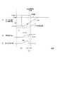
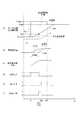
本実施形態の目標値補正処理を図7のタイムチャートに基づいて説明する。図7では、共通時間軸を横軸とし、(a)がモータ角度θmおよび出力軸角度θs、(b)が角度変化量Δθm、Δθs、(c)が変化量差分値Dmsである。なお、説明のため、タイムスケール等は適宜変更しており、実際の時間とは必ずしも一致しない。後述の図10、図13および図14についても同様である。 The target value correction process of this embodiment will be described based on the time chart of FIG. In FIG. 7, the horizontal axis is the common time axis, (a) is the motor angle θm and output shaft angle θs, (b) is the angle variation Δθm, Δθs, and (c) is the variation difference value Dms. For the sake of explanation, the time scale or the like is changed as appropriate and does not necessarily match the actual time. The same applies to FIGS. 10, 13 and 14 described later.
時刻x11にて、ドライバ要求シフトレンジが変更され、通電フラグがオフからオンに切り替わり、モータ角度目標値が設定される。ここで設定される目標値は、仮値θcmd_aである。仮値θcmd_aが設定され、位置フィードバック制御によりモータ10が駆動されると、図7(a)、(b)に示すように、モータ角度θmが変化し、モータ角度変化量Δθm≠0となる。一方、出力軸角度θsは、ガタ空走中は、モータ10の回転が出力軸15に伝達されないので、変化せず、出力軸角度変化量Δθs=0が継続される。また、図7(c)に示すように、ガタ空走区間の間は、変化量差分値Dmsが増加する。 At time x11, the driver request shift range is changed, the energization flag is switched from OFF to ON, and the motor angle target value is set. The target value set here is the provisional value θcmd_a. When the provisional value θcmd_a is set and the
時刻x12にて、ガタ空走が終了すると、モータ10の回転が出力軸15に伝達されるので、出力軸15が回転され、出力軸角度θsが変化し、出力軸角度変化量Δθs≠0となる。また、時刻x13にて、モータ角度変化量Δθmと出力軸角度変化量Δθsとが一致し、変化量差分値Dmsが0となる。本実施形態では、モータ角度変化量Δθmと出力軸角度変化量Δθsとが略一致し、かつ、モータ角度変化量Δθmおよび出力軸角度変化量Δθsが共に回転判定閾値Dr以上となった時刻x13にて、ガタ空走が終了したと判定し、このときのモータ角度θmを角度補正値θpとする。 When the idle running ends at time x12, the rotation of the
また、時刻x13から継続判定値Cthに対応する継続期間が経過した時刻x14にて、角度補正値θpを用いて目標値を補正し、モータ角度目標値θcmdを式(3)の値に変更する。その後、モータ角度θmがモータ角度目標値θcmdとなるように、モータ10を制御する。なお、図7では、モータ角度目標値θcmdが仮値θcmd_aより小さくなるように補正されているが、仮値θcmd_aの設定等に応じ、仮値θcmd_aより大きくなるように補正されてもよい。 Further, at time x14 when the duration corresponding to the continuation determination value Cth has elapsed from time x13, the target value is corrected using the angle correction value θp, and the motor angle target value θcmd is changed to the value of equation (3). . Thereafter, the
本実施形態では、モータ角度θmおよび出力軸角度θsの変化量に基づいてガタ空走終了を判定し、ガタ空走終了判定時のモータ角度θmに基づいて、目標値を補正している。これにより、例えばモータを両方向に回転させて遊びの両端に当接させることによる遊び量の学習処理を行うことなく、モータ角度目標値θcmdを適切に設定することができる。 In the present embodiment, the end of backlash is determined based on the amount of change in the motor angle θm and the output shaft angle θs, and the target value is corrected based on the motor angle θm at the end of backlash determination. Thus, for example, the motor angle target value θcmd can be appropriately set without performing a play amount learning process by rotating the motor in both directions and contacting both ends of the play.
また、比較例として、出力軸角度θsの値そのものを用いてモータ角度目標値θcmdを設定する場合、出力軸センサ16には、絶対角度としての高い検出精度が要求される。これに対し本実施形態では、モータ角度θmおよび出力軸角度θsの変化量に基づいてガタ空走終了を判定し、ガタ空走終了時のモータ角度θmを角度補正値θpとしているので、変化量が適切に検出されていればよく、出力軸角度θsの値そのものを用いる場合と比較し、精度要求を緩和することができる。 As a comparative example, when the motor angle target value θcmd is set using the output shaft angle θs itself, the
さらにまた、比較例として、出力軸角度θsの変化量に基づいてガタ空走終了を検出し、目標値を補正する場合、外乱等の影響にて検出値にノイズが生じると、ガタ空走終了を誤判定する虞がある。本実施形態では、エンコーダ13の検出値に基づくモータ角度θm、および、出力軸センサ16の検出値に基づく出力軸角度θsを用いる異種多重系とし、モータ角度θmおよび出力軸角度θsの変化量に基づいてガタ空走終了を判定しているので、外乱ノイズによるガタ空走終了の誤判定およびモータ角度目標値θcmdの誤補正を回避することができる。 Furthermore, as a comparative example, when the end of backlash detection is detected based on the amount of change in the output shaft angle θs and the target value is corrected, if noise occurs in the detected value due to the influence of disturbance or the like, the backlash end May be erroneously determined. In this embodiment, a heterogeneous multiplex system using the motor angle θm based on the detection value of the
以上説明したように、シフトレンジ制御装置40は、モータ10の回転軸であるモータ軸105とモータ10の回転が伝達される出力軸15との間に遊びが存在するシフトバイワイヤシステム1において、モータ10の回転角度であるモータ角度θmがモータ角度目標値θcmdと一致するようにモータ10の駆動を制御することでシフトレンジを切り替えるものである。シフトレンジ制御装置40は空走判定部521、および、目標値設定部525を備える。 As described above, the shift
空走判定部521は、モータ10の回転を検出するエンコーダ13の検出値に基づく値であるモータ角度θm、および、出力軸15の回転を検出する出力軸センサ16の検出値に基づく値である出力軸角度θsに基づき、遊びの範囲内にてモータ10が回転している空走の終了を判定する。
目標値設定部525は、空走終了時におけるモータ角度θmに応じた値である角度補正値θpを用い、モータ10の駆動制御に係るモータ角度目標値θcmdを設定する。The idle
The target
本実施形態では、モータ角度θmおよび出力軸角度θsを用いて空走状態の終了を判定し、空走終了時のモータ角度θmに基づいて、モータ角度目標値θcmdを設定している。これにより、遊び量の学習処理を行うことなく、モータ角度目標値θcmdを適切に設定することができる。また、モータ角度θmおよび出力軸角度θsの2つの異なる種類の検出値を空走終了判定に用いているので、出力軸角度θsのみに基づいて判定する場合と比較し、出力軸角度θsの検出精度要求を緩和可能であるとともに、外乱ノイズ等の影響によりモータ角度目標値θcmdが誤った値に設定されるのを防ぐことができる。 In this embodiment, the end of the idling state is determined using the motor angle θm and the output shaft angle θs, and the motor angle target value θcmd is set based on the motor angle θm at the end of idling. Thereby, the motor angle target value θcmd can be appropriately set without performing a play amount learning process. In addition, since two different types of detection values of the motor angle θm and the output shaft angle θs are used for the idling determination, the detection of the output shaft angle θs is compared with the case where the determination is based only on the output shaft angle θs. The accuracy requirement can be relaxed, and the motor angle target value θcmd can be prevented from being set to an incorrect value due to the influence of disturbance noise or the like.
空走判定部521は、モータ角度θmの単位時間あたりの変化量であるモータ角度変化量Δθmと、出力軸角度θsの単位時間あたりの変化量である出力軸角度θsとが一致し(図6中のS107:YES)、かつ、モータ角度変化量Δθmおよび出力軸角度変化量Δθsがともに回転判定閾値Dr以上である場合(S108:YES、かつ、S109:YES)、空走状態が終了したと判定する。
これにより、空走状態の終了を適切に判定することができる。The idling
Thereby, the end of the idling state can be appropriately determined.
(第2実施形態)
第2実施形態を図8に基づいて説明する。本実施形態は、目標補正処理が異なっているので、この点を中心に説明する。
本実施形態の目標補正処理を図8に示すフローチャートに基づいて説明する。
S201〜S204の処理は、図6中のS101〜S104の処理と同様である。
S205では、指令演算部52は、変化量差分最大値Dms_maxを0とする。
S206の処理は、図6中のS106の処理と同様である。(Second Embodiment)
A second embodiment will be described with reference to FIG. In the present embodiment, since the target correction process is different, this point will be mainly described.
The target correction process of this embodiment will be described based on the flowchart shown in FIG.
The processing of S201 to S204 is the same as the processing of S101 to S104 in FIG.
In S205, the
The process of S206 is the same as the process of S106 in FIG.
モータ角度θmと駆動初期値θinitとの差の絶対値が駆動初期判定値θa未満であると判断された場合(S206:YES)に移行するS207では、指令演算部52は、変化量差分値Dmsの今回値が、RAM等に記憶されている変化量差分最大値Dms_maxより大きいか否かを判断する。変化量差分値Dmsの今回値が変化量差分最大値Dms_max以下であると判断された場合(S207:NO)、S210へ移行する。変化量差分値Dmsの今回値が変化量差分最大値Dms_maxより大きいと判断された場合(S207:YES)、S208へ移行する。 In S207, where the absolute value of the difference between the motor angle θm and the drive initial value θinit is determined to be less than the drive initial determination value θa (S206: YES), the
S208では、指令演算部52は、変化量差分値Dmsの今回値を、変化量差分最大値Dms_maxとしてRAM等に記憶させる。
S209では、指令演算部52は、角度補正値θpを、モータ角度θmの今回値とし、角度補正値θpをRAM等に記憶させる。In S208, the
In S209, the
S210〜S212の処理は、図6中のS107〜S109の処理と同様である。モータ角度変化量Δθmと出力軸角度変化量Δθsとが一致していない場合(S210:NO)、または、モータ角度変化量Δθmおよび出力軸角度変化量Δθsの少なくとも一方が回転判定閾値Drより小さい場合(S211:NO、または、S212:NO)、S213へ移行する。モータ角度変化量Δθmと出力軸角度変化量Δθsとが一致しており(S210:YES)、かつ、モータ角度変化量Δθmおよび出力軸角度変化量Δθsが共に回転判定閾値Dr以上である場合(S210:YES、かつ、S211:YES)、S214へ移行する。
S213の処理は、図6中のS111の処理と同様である。
S214〜S216の処理は、図6中のS114〜S116の処理と同様である。The processing of S210 to S212 is the same as the processing of S107 to S109 in FIG. When the motor angle change amount Δθm does not match the output shaft angle change amount Δθs (S210: NO), or when at least one of the motor angle change amount Δθm and the output shaft angle change amount Δθs is smaller than the rotation determination threshold Dr. (S211: NO or S212: NO), the process proceeds to S213. When the motor angle change amount Δθm and the output shaft angle change amount Δθs match (S210: YES), and both the motor angle change amount Δθm and the output shaft angle change amount Δθs are greater than or equal to the rotation determination threshold Dr (S210). : YES and S211: YES), the process proceeds to S214.
The process of S213 is the same as the process of S111 in FIG.
The processing of S214 to S216 is the same as the processing of S114 to S116 in FIG.
本実施形態では、変化量差分値Dmsの今回値がこれまでの最大値より大きい場合、変化量差分最大値Dms_maxおよび角度補正値θpを更新する。一方、変化量差分値Dmsの今回値が、これまでの最大値以下の場合、S208およびS209の処理が行われないので、これまでの変化量差分最大値Dms_maxおよび角度補正値θpが保持される。これにより、変化量差分値Dmsのピーク時のモータ角度θmが角度補正値θpとして保持される。換言すると、本実施形態では、変化量差分値Dmsのピークを検出し、変化量差分値Dmsのピーク時のモータ角度θmを角度補正値θpとしている、ということである。すなわち、本実施形態では、図7の時刻x12のときのモータ角度θmを角度補正値θpとしている。
また、変化量差分値Dmsのピークを検出することは、モータ角度変化量Δθmの変化速度が変わる変曲点を検出することと同義である、といえる。さらにまた、変化量差分値Dmsを検出することは、出力軸角度変化量Δθsの変化速度が変わる変曲点を検出することと同義である、といえる。In the present embodiment, when the current value of the change amount difference value Dms is larger than the maximum value so far, the change amount difference maximum value Dms_max and the angle correction value θp are updated. On the other hand, if the current value of the change amount difference value Dms is equal to or less than the maximum value so far, the processing of S208 and S209 is not performed, and thus the change amount difference maximum value Dms_max and the angle correction value θp so far are held. . Accordingly, the motor angle θm at the peak of the change amount difference value Dms is held as the angle correction value θp. In other words, in this embodiment, the peak of the change amount difference value Dms is detected, and the motor angle θm at the peak of the change amount difference value Dms is used as the angle correction value θp. That is, in this embodiment, the motor angle θm at time x12 in FIG. 7 is set as the angle correction value θp.
Moreover, it can be said that detecting the peak of the change amount difference value Dms is synonymous with detecting an inflection point where the change speed of the motor angle change amount Δθm changes. Furthermore, it can be said that detecting the change amount difference value Dms is synonymous with detecting an inflection point at which the change speed of the output shaft angle change amount Δθs changes.
本実施形態では、目標値設定部525は、モータ角度変化量Δθmと出力軸角度変化量Δθsとの差分値である変化量差分値Dmsがピーク値となったときのモータ角度θmを、空走終了時におけるモータ角度θmとみなし、当該モータ角度θmを角度補正値θpとして、モータ角度目標値θcmdを設定する。
これにより、角度補正値θpを適切に設定することができる。
また、上記実施形態と同様の効果を奏する。In the present embodiment, the target
Thereby, the angle correction value θp can be set appropriately.
In addition, the same effects as those of the above embodiment can be obtained.
(第3実施形態)
第3実施形態を図9および図10に基づいて説明する。本実施形態は、目標補正処理における空走判定が異なっているので、この点を中心に説明する。
本実施形態の目標補正処理を図9に示すフローチャートに基づいて説明する。図9は、図6のS107〜S109に替えて、S121およびS122となっている点が第1実施形態と異なる。また、図8中のS210〜S212に替えて、S121およびS122としてもよい。
S101では、指令演算部52は、上述のフィルタ処理等に加え、モータ角度θmと出力軸角度θsとの差である角度差分値θms(式(4)参照)、および、角度差分値θmsの単位時間あたりの変化量である角度差分値変化量Δθmsを演算する。
θms=θm−θs ・・・(4)(Third embodiment)
A third embodiment will be described with reference to FIGS. 9 and 10. In the present embodiment, since the idling determination in the target correction process is different, this point will be mainly described.
The target correction process of this embodiment will be described based on the flowchart shown in FIG. 9 differs from the first embodiment in that S121 and S122 are used instead of S107 to S109 in FIG. Moreover, it is good also as S121 and S122 instead of S210-S212 in FIG.
In S101, in addition to the above-described filter processing and the like, the
θms = θm−θs (4)
S121は、モータ角度θmと駆動初期値θinitとの差の絶対値が駆動初期判定値θa未満であると判断された場合(S106:YES)、すなわちディテントローラ26がレンジ切替前と同一の凹部22内である場合に移行するステップである。S121では、空走判定部521は、角度差分値θmsが差分判定閾値θbより大きいか否かを判断する。角度差分値θmsが差分判定閾値θb以下であると判断された場合(S121:NO)、S111へ移行する。角度差分値θmsが差分判定閾値θbより大きいと判断された場合(S121:YES)、S122へ移行する。 In S121, when it is determined that the absolute value of the difference between the motor angle θm and the drive initial value θinit is less than the drive initial determination value θa (S106: YES), that is, the
S122では、空走判定部521は、角度差分値変化量Δθmsが0か否かを判断する。ここでは、角度差分値変化量Δθmsが、検出誤差等に応じて設定される判定値より小さい場合、角度差分値変化量Δθmsが0であるとみなす。角度差分値変化量Δθmsが0ではないと判断された場合(S122:NO)、S111へ移行する。角度差分値変化量Δθmsが0であると判断された場合(S122:YES)、S110へ移行し、以降の処理を行う。 In S122, the idle
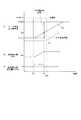
本実施形態の目標値補正処理を図10のタイムチャートに基づいて説明する。図10では、共通時間軸を横軸とし、(a)がモータ角度θmおよび出力軸角度θs、(b)が角度差分値θms、(c)が角度差分値変化量Δθmsである。図10(a)は、角度補正値θpを除き、図7(a)と略同様である。 The target value correction process of this embodiment will be described based on the time chart of FIG. In FIG. 10, the common time axis is the horizontal axis, (a) is the motor angle θm and output shaft angle θs, (b) is the angle difference value θms, and (c) is the angle difference value change amount Δθms. FIG. 10A is substantially the same as FIG. 7A except for the angle correction value θp.
時刻x21にて、ドライバ要求シフトレンジが変更され、モータ10が駆動されると、ガタ空走中は、モータ角度θmは変化するが、出力軸角度θsは変化しない。そのため、図10(b)に示すように、ガタ空走中は、角度差分値θmsは増加する。また、時刻x22にて、ガタ空走区間が終了すると、モータ10と出力軸15とは一体に回転するので、図10(b)に示すように、角度差分値θmsが一定となり、図10(c)に示すように、角度差分値変化量Δθmsが0となる。 When the driver request shift range is changed at time x21 and the
本実施形態では、角度差分値θmsが差分判定閾値θbより大きく、かつ、角度差分値変化量Δθmsが0となった時刻x22にて、ガタ空走が終了したと判定し、このときのモータ角度θmを角度補正値θpとする。
また、時刻x22から、継続判定値Cthに対応する継続期間が経過した時刻x23にて、角度補正値θpを用いて目標値を補正する。その後、モータ角度θmが補正後のモータ角度目標値θcmdとなるように、モータ10を制御する。In the present embodiment, at time x22 when the angle difference value θms is larger than the difference determination threshold θb and the angle difference value change amount Δθms becomes 0, it is determined that the backlash has ended, and the motor angle at this time Let θm be the angle correction value θp.
Further, the target value is corrected using the angle correction value θp at time x23 when the duration corresponding to the continuation determination value Cth has elapsed from time x22. Thereafter, the
本実施形態では、空走判定部521は、モータ角度θmと出力軸角度θsとの差分値である角度差分値θmsが差分判定閾値θbより大きく(図9中のS121:YES)、かつ、角度差分値θmsの単位時間あたりの変化量である角度差分値変化量Δθmsが0となったとき、空走状態が終了したと判定する。
このようにしても、空走状態の終了を適切に判定することができる。
また、上記実施形態と同様の効果を奏する。In the present embodiment, the idling
Even in this case, it is possible to appropriately determine the end of the idling state.
In addition, the same effects as those of the above embodiment can be obtained.
(第4実施形態)
第4実施形態を図11〜図13に示す。本実施形態は、目標補正処理が上記実施形態と異なるので、この点を中心に説明する。
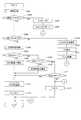
S301〜S303の処理は、図6中のS101〜S103の処理と同様である。
S303に続いて移行するS304では、後述するフラグXgata_A、Xgata_B、Xgata_ABをリセットし、S312へ移行する。(Fourth embodiment)
A fourth embodiment is shown in FIGS. This embodiment is different from the above embodiment in target correction processing, and this point will be mainly described.
The processing of S301 to S303 is the same as the processing of S101 to S103 in FIG.
In S304, which proceeds from S303, flags Xdata_A, Xgata_B, and Xdata_AB, which will be described later, are reset, and the process proceeds to S312.
通電フラグがオンされている場合(S302:YES)に移行するS305の処理は、S106の処理と同様である。モータ角度θmと駆動初期値θinitとの差の絶対値が駆動初期判定値θa以上であると判断された場合(S305:NO)、S315へ移行する。モータ角度θmと駆動初期値θinitとの差の絶対値が駆動初期判定値θa未満であると判断された場合(S305:YES)、S306へ移行する。 The process of S305 that is performed when the energization flag is turned on (S302: YES) is the same as the process of S106. When it is determined that the absolute value of the difference between the motor angle θm and the drive initial value θinit is greater than or equal to the drive initial determination value θa (S305: NO), the process proceeds to S315. When it is determined that the absolute value of the difference between the motor angle θm and the drive initial value θinit is less than the drive initial determination value θa (S305: YES), the process proceeds to S306.
S306では、区間判定処理を行う。
区間判定処理のサブフローを図12に示す。
S361では、空走判定部521は、出力軸角度変化量Δθsが0か否かを判断する。検出誤差等を考慮し、例えば0に近い所定値以下の場合、出力軸角度変化量Δ0が0であると判断する。出力軸角度変化量Δθsが0ではないと判断された場合(S361:NO)、S364へ移行する。出力軸角度変化量Δθsが0であると判断された場合(S361:YES)、S362へ移行する。In S306, section determination processing is performed.
A sub-flow of the section determination process is shown in FIG.
In S361, the idling
S362の処理は、図6中のSS108の処理と同様であって、空走判定部521は、モータ角度変化量Δθmが回転判定閾値Dr以上か否かを判断する。モータ角度変化量Δθmが回転判定閾値Dr以上であると判断された場合(S362:YES)、S363へ移行する。モータ角度変化量Δθmが回転判定閾値Dr未満であると判断された場合(S362:NO)、S364へ移行する。 The process of S362 is the same as the process of SS108 in FIG. 6, and the idling
S363では、空走判定部521は、ガタ空走区間であることを示すフラグAをオンにする。
S364では、空走判定部521は、フラグAをオフにする。
図11〜図13では、フラグAを「Xgata_A」とし、フラグオンの状態を「1」、オフの状態を「0」とする。後述のフラグBおよびフラグABも同様とする。In S363, the free
In S364, the free
11 to 13, the flag A is “Xgata_A”, the flag on state is “1”, and the off state is “0”. The same applies to a flag B and a flag AB described later.
S365では、S362と同様であって、モータ角度変化量Δθmが回転判定閾値Dr未満であると判断された場合(S365:NO)、S370へ移行する。モータ角度変化量Δθmが回転判定閾値Dr以上であると判断された場合(S365:YES)、S366へ移行する。 In S365, it is the same as S362, and when it is determined that the motor angle change amount Δθm is less than the rotation determination threshold Dr (S365: NO), the process proceeds to S370. When it is determined that the motor angle change amount Δθm is greater than or equal to the rotation determination threshold Dr (S365: YES), the process proceeds to S366.
S366では、図6中のS109と同様、空走判定部521は、出力軸角度変化量Δθsが回転判定閾値Dr以上か否かを判断する。出力軸角度変化量Δθsが回転判定閾値Dr未満であると判断された場合(S366:NO)、S370へ移行する。出力軸角度変化量Δθsが回転判定閾値Dr以上であると判断された場合(S366:YES)、S367へ移行する。 In S366, as in S109 in FIG. 6, the free
S367では、図6中のS107と同様であって、変化量差分値Dmsの絶対値が一致判定閾値Db以上であると判断された場合(S367:NO)、すなわちモータ角度変化量Δθmと出力軸角度変化量Δθsとが一致しない場合、S369へ移行する。変化量差分値Dmの絶対値が一致判定閾値Db未満であると判断された場合(S367:YES)、すなわちモータ角度変化量Δθmと出力軸角度変化量Δθsとが一致する場合、S368へ移行する。 S367 is the same as S107 in FIG. 6, and when it is determined that the absolute value of the change amount difference value Dms is greater than or equal to the coincidence determination threshold value Db (S367: NO), that is, the motor angle change amount Δθm and the output shaft If the angle change amount Δθs does not match, the process proceeds to S369. When it is determined that the absolute value of the change amount difference value Dm is less than the coincidence determination threshold value Db (S367: YES), that is, when the motor angle change amount Δθm matches the output shaft angle change amount Δθs, the process proceeds to S368. .
S368では、空走判定部521は、モータ10と出力軸15とが一致して回転している区間であることを示すフラグBをセットする。
S369では、空走判定部521は、ガタ空走状態からモータ10と出力軸15とが一体となって回転する状態への移行区間であることを示すフラグABをセットする。
S370では、フラグBおよびフラグABをオフにする。In S368, the idling
In S369, the idle
In S370, the flag B and the flag AB are turned off.
図11に戻り、区間判定処理に続いて移行するS307では、空走判定部521は、フラグAがオンか否かを判断する。フラグAがオフであると判断された場合(S307:NO)、S309へ移行する。フラグAがオンであると判断された場合(S307:YES)、S308へ移行する。
フラグAがオンである場合、すなわち空走状態である場合に移行するS308では、空走判定部521は、計時カウンタのカウント値Ctをx座標、モータ角度変化量Δθmをy座標とし、区間Aにおけるモータ角度変化量Δθmの近似直線を導出する。区間Aにおけるモータ角度変化量Δθmの近似直線を式(5)とする。
y=ax+b ・・・(5)Returning to FIG. 11, in S <b> 307 following the section determination process, the idling
When the flag A is ON, that is, in S308 that is shifted to the idling state, the idling
y = ax +b (5)
フラグAがオフであると判断された場合(S307:NO)に移行するS309では、空走判定部521は、フラグBがオンか否かを判断する。フラグBがオフであると判断された場合(S309:NO)、S311へ移行する。フラグBがオンであると判断された場合(S309:YES)、S310へ移行する。 In S309, when the flag A is determined to be off (S307: NO), the idling
フラグBがオンである場合、すなわちモータ10と出力軸15とが一体回転している場合に移行するS310では、空走判定部521は、計時カウンタのカウント値Ctをx座標、モータ角度変化量Δθmをy座標とし、区間Bにおけるモータ角度変化量Δθmの近似直線を導出する。区間Bにおけるモータ角度変化量Δθmの近似直線を式(6)とする。
y=cx+d ・・・(6)
以下、区間Aにおけるモータ角度変化量Δθmの近似直線を「近似直線LA」、区間Bにおけるモータ角度変化量Δθmの近似直線を「近似直線LB」と呼ぶ。When the flag B is ON, that is, when the
y = cx + d (6)
Hereinafter, the approximate straight line of the motor angle change amount Δθm in the section A is referred to as “approximate straight line LA”, and the approximate straight line of the motor angle change amount Δθm in the section B is referred to as “approximate straight line LB”.
フラグA、Bが共にオフである場合(S307:NO、かつ、S309:NO)に移行するS311では、空走判定部521は、フラグABがオンか否かを判断する。フラグABがオンであると判断された場合(S311:YES)、S313へ移行する。フラグABがオフであると判断された場合(S311:NO)、S312へ移行する。 In S311, the process proceeds to the case where both the flags A and B are off (S307: NO and S309: NO), the idle
S311で否定判断された場合、または、S304に続いて移行するS312では、空走判定部521は、計時カウンタのカウント値Ctをリセットする。
フラグA、B、ABのいずれかがオンである場合に移行するS313では、空走判定部521は、現在の計時カウンタのカウント値Ctと、モータ角度θmと、モータ角度変化量Δθmと、フラグ状態とを関連づけて、図示しないメモリに記憶させる。
S314では、空走判定部521は、計時カウンタのカウント値Ctをインクリメントする。When a negative determination is made in S311, or in S312 that moves on following S304, the idle
In S313, which proceeds when any of the flags A, B, and AB is on, the idling
In S314, the idling
モータ角度θmと駆動初期値θinitとの差の絶対値が駆動初期判定値θa以上であると判断された場合(S305:NO)に移行するS315では、空走判定部521は、近似直線LA、LBの交点を演算する。本実施形態では、モータ角度変化量Δθmが変曲点となるタイミングにて、空走状態が終了したと判定する。モータ角度変化量Δθmの変曲点は、近似直線LA、LBの交点とする。近似直線LA、LBの交点のx座標を「ガタ詰めポイントXX」とすると、ガタ詰めポイントXXは、式(7)で表される。XXが負の値となった場合は、XX=0とする。
XX=(d−b)/(a−c) ・・・(7)In S315, when the absolute value of the difference between the motor angle θm and the drive initial value θinit is determined to be equal to or greater than the drive initial determination value θa (S305: NO), the idle
XX = (db) / (ac) (7)
S316では、指令演算部52は、ガタ詰めポイントXXと最も近いカウント値Ctと関連づけて記憶されているモータ角度θmを、角度補正値θpとする。本実施形態では、カウント値Ctおよびモータ角度θmは離散値であるので、ガタ詰めポイントXXと最も近いカウント値Ctを「空走終了時」とみなし、当該カウント値Ctのときのモータ角度θmに基づいて角度補正値θpを設定する。
S317では、図6中のS116と同様、目標値設定部525は、角度補正値θpを用いてモータ角度目標値θcmdを演算する。In S316, the
In S317, similar to S116 in FIG. 6, the target
ここで、近似直線LA、LBの導出について説明する。本実施形態では、S313にて、計時カウンタのカウント値Ctとモータ角度変化量Δθmとが関連づけてメモリに記憶されている。本実施形態では、フラグAと関連付けられている複数の(Ct,Δθm)を用いて、例えば最小二乗法等により線形近似を行い、近似直線LAを導出する。同様に、フラグBと関連付けられている複数の(Ct,Δθm)を用いて、例えば最小二乗法等により、線形近似を行い、近似直線LBを導出する。
なお、近似直線LA、LBを、最小二乗法以外の方法にて導出してもよい。また、線形近似に限らず、二次以上の関数等の近似線を導出し、当該近似線を用いて空走終了を判定してもよい。Here, the derivation of the approximate straight lines LA and LB will be described. In the present embodiment, in S313, the count value Ct of the time counter and the motor angle change amount Δθm are associated with each other and stored in the memory. In the present embodiment, using a plurality of (Ct, Δθm) associated with the flag A, for example, linear approximation is performed by the least square method or the like to derive an approximate line LA. Similarly, using a plurality of (Ct, Δθm) associated with the flag B, linear approximation is performed by, for example, the least square method or the like to derive an approximate line LB.
The approximate straight lines LA and LB may be derived by a method other than the method of least squares. Moreover, not only linear approximation but approximate lines such as quadratic or higher functions may be derived, and the end of idle running may be determined using the approximate lines.
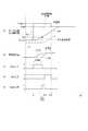
本実施形態の目標値補正処理を図13のタイムチャートに基づいて説明する。図13は、共通時間軸を横軸とし、(a)がモータ角度θmおよび出力軸角度θs、(b)が角度変化量Δθm、Δθs、(c)がフラグA、(d)がフラグB、(e)がフラグABである。図13では、横軸を計時カウンタのカウント値Ctに読み替えているが、(a)、(b)の詳細については、図7と同様である。図14についても同様である。 The target value correction process of this embodiment will be described based on the time chart of FIG. In FIG. 13, the horizontal axis is the common time axis, (a) is the motor angle θm and output shaft angle θs, (b) is the angle variation Δθm, Δθs, (c) is the flag A, (d) is the flag B, (E) is the flag AB. In FIG. 13, the horizontal axis is read as the count value Ct of the time counter, but details of (a) and (b) are the same as in FIG. The same applies to FIG.
図13に示すように、ガタ空走区間と谷谷間回転区間とでは、モータ角度変化量Δθmの傾きが異なっている。本実施形態では、ガタ空走状態が終了する「ガタ詰まり」となると、モータ角度変化量Δθmの傾きが変化し、変曲点となることを利用して、ガタ詰めポイントXXを決定している。 As shown in FIG. 13, the inclination of the motor angle change amount Δθm is different between the idle running section and the valley rotation section. In the present embodiment, when the loose running state ends, “clogging”, the inclination of the motor angle change amount Δθm changes, and the inflection point is used to determine the backlash point XX. .
カウント値0からCt1までの区間Aは、ガタ空走区間である。区間Aにおいては、モータ角度変化量Δθm≠0であり、出力軸角度変化量Δθs=0であって、フラグAがオンされている。この間、(Ct,Δθm)に基づき、近似直線LAを更新していく。カウント値Ct1にて、出力軸角度変化量Δθs≠0となると、フラグAをオフにする。このとき、近似直線LAが確定される。 The section A from the
カウント値Ct1から、モータ角度変化量Δθmと出力軸角度変化量Δθsとが一致するカウント値Ct2までの間は、フラグABがセットされる。フラグABがオンのときは、ガタ空走完了から、モータ10と出力軸15とが一体となって回転するまでの移行区間であるので、近似直線LA、LBの演算を行わない。この間において、カウント値Ct、モータ角度θm、モータ角度変化量Δθmおよびフラグ状態の記憶は継続する。 The flag AB is set between the count value Ct1 and the count value Ct2 where the motor angle change amount Δθm and the output shaft angle change amount Δθs match. When the flag AB is on, since it is a transitional section from the completion of the idle running until the
カウント値Ct2にて、モータ角度変化量Δmと出力軸角度変化量Δθsとが一致すると、フラグABをオフにし、フラグBをオンにする。モータ角度θmと駆動初期値θinitとの差の絶対値が駆動初期判定値θa以上となるカウント値Ct3までの間、フラグBがオンされている。この間、(Ct,Δθm)に基づき、近似直線LBを更新していく。カウント値Ct3にて、モータ角度θmと駆動初期値θinitとの差の絶対値が駆動初期判定値θa以上になると、近似直線LBが確定される。 When the motor angle change amount Δm matches the output shaft angle change amount Δθs at the count value Ct2, the flag AB is turned off and the flag B is turned on. The flag B is turned on until the absolute value of the difference between the motor angle θm and the drive initial value θinit is equal to or greater than the count value Ct3 that is equal to or greater than the drive initial determination value θa. During this time, the approximate straight line LB is updated based on (Ct, Δθm). When the absolute value of the difference between the motor angle θm and the drive initial value θinit becomes equal to or greater than the drive initial determination value θa at the count value Ct3, the approximate straight line LB is determined.
そして、得られた近似直線LA、LBを用いて、ガタ詰めポイントXXを演算し、ガタ詰めポイントXXにおけるモータ角度θmを角度補正値θpとする。そして、角度補正値θpに基づいてモータ角度目標値θcmdを演算し、仮値θcmd_aを、演算されたモータ角度目標値θcmdに変更する。実際には、カウント値Ct3にて近似直線LBが確定されてから、モータ角度目標値θcmdが変更されるまでには、演算遅れがあるが、ここでは簡略化のため、カウント値Ct3にてモータ角度目標値θcmdが変更されるものとして記載した。また、モータ角度目標値θcmdの変更は、カウント値Ct3以降であって、ディテントローラ26がディテントプレート21の山を越える前のいずれのタイミングとしてもよい。Then, using the obtained approximate straight lines LA and LB, the backlash point XX is calculated, and the motor angle θm at the backlash point XX is set as the angle correction value θp. Then, the motor angle target value θcmd is calculated based on the angle correction value θp, and the temporary value θcmd_a is changed to the calculated motor angle target value θcmd. Actually, there is a calculation delay until the motor angle target value θcmd is changed after the approximate straight line LB is determined at the count value Ct3 , but here the count value Ct3 is used for simplification. The motor angle target value θcmd is described as being changed. Further, the change of the motor angle target value θcmd may be any timing after the count value Ct3 and before the
図13中では、区間Aの終了タイミングとガタ詰めポイントXXとが一致するものとして記載しているが、演算結果によっては、演算されたガタ詰めポイントXXが、区間Aの終了タイミングとずれていても、差し支えない。また、図13の例では、区間Aが区間Bより長いが、区間A、Bの長さは、モータ始動時のモータ軸105のガタ内での位置や、駆動初期判定値θaの設定等により、区間Bよりも区間Aが長いとは限らない。図14および図15においても同様である。 In FIG. 13, it is described that the end timing of the section A coincides with the backlash point XX. However, depending on the calculation result, the calculated backlash point XX is shifted from the end timing of the section A. However, there is no problem. In the example of FIG. 13, the section A is longer than the section B, but the length of the sections A and B depends on the position of the
本実施形態では、空走判定部512は、モータ角度θmおよび出力軸角度θsに基づき、区間Aおよび区間Bを設定する。詳細には、空走判定部512は、モータ角度変化量Δθmおよび出力軸角度変化量Δθsに基づき、空走状態である区間A、および、モータ軸105と出力軸15とが一体回転している区間Bを設定する。
空走判定部512は、区間Aにおけるモータ角度変化量Δθmの経時変化を表す近似直線LA、および、区間Bにおけるモータ角度変化量Δθmの経時変化を表す近似直線LBを導出する。空走判定部512は、近似直線LA、LBの交点となるタイミングにて、空走状態が終了したとみなす。In the present embodiment, the idling determination unit 512 sets the section A and the section B based on the motor angle θm and the output shaft angle θs. Specifically, the idle running determination unit 512 is based on the motor angle change amount Δθm and the output shaft angle change amount Δθs, and the idle running section A, and the
The idling determination unit 512 derives an approximate straight line LA that represents a change over time of the motor angle change amount Δθm in the section A and an approximate straight line LB that represents a change over time of the motor angle change amount Δθm in the section B. The free running determination unit 512 considers that the free running state has ended at the timing of the intersection of the approximate straight lines LA and LB.
本実施形態では、複数の時点でのモータ角度変化量Δθmを用いて近似直線LA、LBを求め、その交点に基づいて空走終了判定を行い、角度補正値θpを演算している。これにより、エンコーダ13や出力軸センサ16におけるノイズの影響により空走終了を誤判定しにくくなり、空走終了判定および角度補正値θpの精度が向上する。
また、上記実施形態と同様の効果を奏する。In the present embodiment, the approximate straight lines LA and LB are obtained using the motor angle change amounts Δθm at a plurality of time points, the idle running end determination is performed based on the intersections, and the angle correction value θp is calculated. Thereby, it becomes difficult to erroneously determine the end of idling due to the influence of noise in the
In addition, the same effects as those of the above embodiment can be obtained.
本実施形態では、区間Aが「空走区間」、区間Bが「一体回転区間」、近似直線LAが「第1近似線」、近似直線LBが「第2近似線」に対応する。「空走区間」は、空走状態である期間の全体である必要はなく、空走状態である期間の一部であってもよい。「一体回転区間」は、モータ10と出力軸15とが一体となって回転している期間の一部であって、ディテントローラ26がシフトレンジ切替前と同一の凹部22内である範囲内の任意の期間とする。
また、本実施形態では、区間A、Bの設定にモータ角度θmおよび出力軸角度θsを用いており、本実施形態のように近似直線LA、LBに基づいて空走状態の終了を判定することは、「モータ角度および出力軸角度に基づき、空走状態の終了を判定する」という概念に含まれるものとする。
第5実施形態および第6実施形態についても同様である。In the present embodiment, the section A corresponds to the “free running section”, the section B corresponds to the “integral rotation section”, the approximate straight line LA corresponds to the “first approximate line”, and the approximate straight line LB corresponds to the “second approximate line”. The “idle running section” does not have to be the entire period during which the vehicle is idle, and may be a part of the period during which the vehicle is idle. The “integral rotation section” is a part of a period in which the
In the present embodiment, the motor angle θm and the output shaft angle θs are used to set the sections A and B, and the end of the idling state is determined based on the approximate straight lines LA and LB as in the present embodiment. Is included in the concept of “determining the end of the idling state based on the motor angle and the output shaft angle”.
The same applies to the fifth and sixth embodiments.
(第5実施形態)
第5実施形態を図14に示す。第5実施形態および第6実施形態では、近似直線LA、LBが第4実施形態と異なっているので、この点を中心に説明し、その他の点については省略する。
図14は、共通時間軸を横軸とし、(a)がモータ角度θmおよび出力軸角度θs、(b)が角度変化量Δθm、Δθs、(c)が角度差分値θms、(d)がフラグA、(e)がフラグB、(f)がフラグABである。(Fifth embodiment)
A fifth embodiment is shown in FIG. In the fifth embodiment and the sixth embodiment, the approximate lines LA and LB are different from those in the fourth embodiment. Therefore, this point will be mainly described, and other points will be omitted.
In FIG. 14, the horizontal axis is the common time axis, (a) is the motor angle θm and output shaft angle θs, (b) is the angle variation Δθm, Δθs, (c) is the angle difference value θms, and (d) is the flag. A, (e) is a flag B, and (f) is a flag AB.
第4実施形態では、区間A、Bのモータ角度変化量Δθmの近似直線を求め、その交点に基づいて空走終了判定を行う。
本実施形態では、モータ角度変化量Δθmに替えて、モータ角度θmと出力軸角度θsとの差である角度差分値θms(式(4)参照)を用い、区間Aにおける角度差分値θmsの近似直線を近似直線LA、区間Bにおける角度差分値θmsの近似直線を近似直線LBとし、近似直線LA、LBの交点に基づいて空走終了を判定する。In the fourth embodiment, an approximate straight line of the motor angle change amount Δθm in the sections A and B is obtained, and the idle running end determination is performed based on the intersection.
In this embodiment, instead of the motor angle change amount Δθm, an angle difference value θms (see formula (4)) that is a difference between the motor angle θm and the output shaft angle θs is used to approximate the angle difference value θms in the section A. The straight line is the approximate straight line LA, the approximate straight line of the angle difference value θms in the section B is the approximate straight line LB, and the end of idle running is determined based on the intersection of the approximate straight lines LA and LB.
図14に示すように、ガタ空走区間と谷谷間回転区間とでは、角度差分値θmsの傾きが異なっている。本実施形態では、「ガタ詰まり」となると、角度差分値θmsの傾きが変化し、変曲点となることを利用して、ガタ詰めポイントXXおよび角度補正値θpを決定している。
近似直線LA、LBの導出方法、ならびに、ガタ詰めポイントXXおよび角度補正値θpの決定方法等の詳細は、モータ角度変化量Δθmに替えて、角度差分値θmsを用いれば、第4実施形態と同様である。As shown in FIG. 14, the inclination of the angle difference value θms differs between the loose running section and the valley-rotating section. In the present embodiment, when the “backlash clogging” occurs, the backlash point XX and the angle correction value θp are determined by utilizing the fact that the inclination of the angle difference value θms changes and becomes an inflection point.
The details of the method for deriving the approximate straight lines LA and LB, and the method for determining the backlash point XX and the angle correction value θp are the same as those in the fourth embodiment if the angle difference value θms is used instead of the motor angle change amount Δθm. It is the same.
ここでは、角度差分値θmsは、式(4)のように、モータ角度θmから出力軸角度θsを減算するものとして説明したが、出力軸角度θsからモータ角度θmを減算した値を「角度差分値」としてもよい。角度差分値θmsは、ガタ空走区間が終了すると、0になる値であることを鑑みれば、「ガタ空走量」と捉えることもできる。第3実施形態についても同様である。 Here, the angle difference value θms has been described as subtracting the output shaft angle θs from the motor angle θm as shown in Equation (4), but the value obtained by subtracting the motor angle θm from the output shaft angle θs is expressed as “angle difference”. Value "may be used. In view of the fact that the angle difference value θms is a value that becomes 0 when the backlash running section ends, it can also be regarded as “backlash running amount”. The same applies to the third embodiment.
本実施形態では、空走判定部512は、区間Aにおける角度差分値θmsの経時変化を表す近似直線LA、および、区間Bにおける角度差分値θmsの経時変化を表す近似直線LBを導出する。空走判定部512は、近似直線LA、LBの交点となるタイミングにて、空走状態が終了したとみなす。
本実施形態では、複数時点での角度差分値θmsを用いて近似直線LA、LBを求め、その交点に基づいて空走終了判定を行い、角度補正値θpを演算している。これにより、エンコーダ13や出力軸センサ16におけるノイズの影響により空走終了を誤判定しにくくなる。また、近似直線LA、LBの導出にも、2つのセンサ値を用いているので、空走終了判定および角度補正値θpの精度がより向上する。
また、上記実施形態と同様の効果を奏する。In the present embodiment, the idling determination unit 512 derives an approximate straight line LA that represents a change over time in the angle difference value θms in the section A and an approximate straight line LB that represents a change over time in the angle difference value θms in the section B. The free running determination unit 512 considers that the free running state has ended at the timing of the intersection of the approximate straight lines LA and LB.
In the present embodiment, the approximate straight lines LA and LB are obtained using the angle difference values θms at a plurality of time points, the idle running end determination is performed based on the intersections, and the angle correction value θp is calculated. This makes it difficult to erroneously determine the end of idling due to the influence of noise in the
In addition, the same effects as those of the above embodiment can be obtained.
(第6実施形態)
第6実施形態では、出力軸角度θsを用い、区間Aにおける出力軸角度θsの近似直線を近似直線LA、区間Bにおける出力軸角度θsの近似直線を近似直線LBとし、近似直線LA、LBの交点に基づいて空走終了を判定する。
図13および図14に示すように、ガタ空走区間と谷谷間回転区間とでは、出力軸角度θsの傾きが異なっている。本実施形態では、「ガタ詰まり」となると、角度差分値θmsの傾きが変化し、変曲点となることを利用して、ガタ詰めポイントXXおよび角度補正値θpを決定している。
近似直線LA、LBの導出方法、ならびに、ガタ詰めポイントXXおよび角度補正値θpの決定方法等の詳細は、モータ角度変化量Δθmに替えて、出力軸角度θsを用いれば、第4実施形態と同様である。(Sixth embodiment)
In the sixth embodiment, the output shaft angle θs is used, the approximate straight line of the output shaft angle θs in the section A is the approximate straight line LA, the approximate straight line of the output shaft angle θs in the section B is the approximate straight line LB, and the approximate straight lines LA and LB The end of idle running is determined based on the intersection.
As shown in FIGS. 13 and 14, the inclination of the output shaft angle θs is different between the loose running section and the valley rotation section. In the present embodiment, when the “backlash clogging” occurs, the backlash point XX and the angle correction value θp are determined by utilizing the fact that the inclination of the angle difference value θms changes and becomes an inflection point.
The details of the method for deriving the approximate straight lines LA and LB, and the method for determining the backlash point XX and the angle correction value θp are the same as in the fourth embodiment if the output shaft angle θs is used instead of the motor angle change amount Δθm. It is the same.
本実施形態では、空走判定部512は、区間Aにおける出力軸角度θsの経時変化を表す近似直線LA、および、区間Bにおける出力軸角度θsの経時変化を表す近似直線LBを導出する。空走判定部512は、近似直線LA、LBの交点となるタイミングにて、空走状態が終了したとみなす。
本実施形態では、複数時点での出力軸角度θsを用いて近似直線LA、LBを求め、その交点に基づいて空走終了判定を行うとともに角度補正値θpを演算しているので、ノイズの影響により空走終了を誤判定しにくくなる。
また、上記実施形態と同様の効果を奏する。In the present embodiment, the idling determination unit 512 derives an approximate straight line LA that represents a change with time in the output shaft angle θs in the section A and an approximate straight line LB that represents a change with time in the output shaft angle θs in the section B. The free running determination unit 512 considers that the free running state has ended at the timing of the intersection of the approximate straight lines LA and LB.
In the present embodiment, the approximate straight lines LA and LB are obtained using the output shaft angles θs at a plurality of points in time, the idle running end determination is performed based on the intersections, and the angle correction value θp is calculated. This makes it difficult to mistakenly determine the end of idling.
In addition, the same effects as those of the above embodiment can be obtained.
(他の実施形態)
上記実施形態では、モータは、永久磁石式の3相ブラシレスモータである。他の実施形態では、モータは、スイッチトリラクタンスモータ等、どのようなモータを用いてもよい。また、上記実施形態では、モータに2組の巻線組が設けられる。他の実施形態では、モータの巻線組は、1組でもよいし3組以上であってもよい。(Other embodiments)
In the embodiment, the motor is a permanent magnet type three-phase brushless motor. In other embodiments, the motor may be any motor such as a switched reluctance motor. In the above embodiment, the motor is provided with two winding sets. In another embodiment, the number of winding sets of the motor may be one or more than three.
上記実施形態では、位置フィードバック制御において、120°通電による矩形波制御を行う。他の実施形態では、位置フィードバック制御において、180°通電による矩形波制御としてもよい。また矩形波制御に限らず、三角波比較方式や瞬時ベクトル選択方式によるPWM制御としてもよい。 In the above embodiment, rectangular wave control by 120 ° energization is performed in the position feedback control. In another embodiment, the position feedback control may be rectangular wave control by 180 ° energization. Further, not limited to rectangular wave control, PWM control using a triangular wave comparison method or an instantaneous vector selection method may be used.
上記実施形態では、モータ制御状態として、位置フィードバック制御と固定相通電制御とを切り替える。他の実施形態では、モータ駆動制御部は、位置フィードバック制御および固定相通電制御の少なくとも一方を異なる制御状態としてもよい。また、上記実施形態では、位置フィードバック制御と固定相通電制御とを切り替える。他の実施形態では、モータの制御状態を切り替えず、例えば位置フィードバック制御等、1つの制御状態にてモータの駆動を制御するようにしてもよい。また、速度フィードバック制御としてもよい。
モータの制御方法は、用いるモータの種類に応じ、適宜変更可能である。In the above embodiment, the position feedback control and the stationary phase energization control are switched as the motor control state. In another embodiment, the motor drive control unit may set at least one of position feedback control and stationary phase energization control to different control states. Moreover, in the said embodiment, position feedback control and stationary phase electricity supply control are switched. In another embodiment, the motor drive state may be controlled in one control state such as position feedback control without switching the motor control state. Moreover, it is good also as speed feedback control.
The motor control method can be appropriately changed according to the type of motor used.
上記実施形態では、モータの回転角を検出する回転角センサとして、エンコーダを用いる。他の実施形態では、回転角センサは、エンコーダに限らず、レゾルバ等、どのようなものを用いてもよい。上記実施形態では、エンコーダのカウント値を位相進みフィルタ処理を行い、位置フィードバック制御に用いる。他の実施形態では、モータの回転角そのもの、または、モータの回転角に換算可能なエンコーダカウント値以外の値を用いて位置フィードバック制御を行ってもよい。固定相通電制御における固定相の選択についても同様である。また他の実施形態では、位相進みフィルタ処理を省略してもよい。
また、出力軸センサは、出力軸の回転に応じて出力が連続的に変化するものであれば、ポテンショメータ以外のものを用いてもよい。In the above embodiment, an encoder is used as a rotation angle sensor that detects the rotation angle of the motor. In another embodiment, the rotation angle sensor is not limited to an encoder, and any other device such as a resolver may be used. In the above embodiment, the count value of the encoder is subjected to phase advance filter processing and used for position feedback control. In another embodiment, the position feedback control may be performed using the rotation angle of the motor itself or a value other than the encoder count value that can be converted into the rotation angle of the motor. The same applies to the selection of the stationary phase in the stationary phase energization control. In other embodiments, the phase advance filter process may be omitted.
As the output shaft sensor, a sensor other than the potentiometer may be used as long as the output continuously changes according to the rotation of the output shaft.
上記実施形態では、ディテントプレートには4つの凹部が設けられる。他の実施形態では、凹部の数は4つに限らず、いくつであってもよい。例えば、ディテントプレートの凹部を2つとし、PレンジとnotPレンジとを切り替えるものとしてもよい。また、シフトレンジ切替機構やパーキングロック機構等は、上記実施形態と異なっていてもよい。 In the above embodiment, the detent plate is provided with four recesses. In other embodiments, the number of recesses is not limited to four and may be any number. For example, it is good also as what changes the P range and the notP range by making the recessed part of a detent plate into two. Further, the shift range switching mechanism, the parking lock mechanism, and the like may be different from those in the above embodiment.
上記実施形態では、モータ軸と出力軸との間に減速機が設けられる。他の実施形態では、モータ軸と出力軸との間の減速機を省略してもよいし、減速機以外の機構を設けてもよい。すなわち、上記実施形態では、モータ軸と出力軸との間の「遊び」が減速機のギアとモータ軸との間に存在するものを中心に説明したが、「遊び」とはモータ軸と出力軸との間に存在する遊びやガタ等の合計と捉えることができる。 In the above embodiment, the speed reducer is provided between the motor shaft and the output shaft. In other embodiments, the speed reducer between the motor shaft and the output shaft may be omitted, or a mechanism other than the speed reducer may be provided. That is, in the above-described embodiment, the description has been made mainly on the case where “play” between the motor shaft and the output shaft exists between the gear of the reduction gear and the motor shaft. It can be considered as the total of play and play existing between the shafts.
他の実施形態では、空走判定については、上記実施形態の判定方法に限らず、出力軸角度およびモータ角度に基づき、どのように判定してもよい。
上記実施形態では、モータ軸角度をギア比換算し、出力軸角度と一致するようにしている。他の実施形態では、出力軸角度をギア比換算してモータ軸角度と一致するようにしてもよい。また、モータ軸と出力軸との間に変速機が設けられていない場合等、適宜、ギア比換算を省略してもよい。
以上、本発明は、上記実施形態になんら限定されるものではなく、発明の趣旨を逸脱しない範囲において種々の形態で実施可能である。In another embodiment, the idling determination is not limited to the determination method of the above embodiment, and may be determined in any manner based on the output shaft angle and the motor angle.
In the above embodiment, the motor shaft angle is converted into a gear ratio so as to coincide with the output shaft angle. In another embodiment, the output shaft angle may be converted to a gear ratio so as to coincide with the motor shaft angle. Further, the gear ratio conversion may be omitted as appropriate, for example, when a transmission is not provided between the motor shaft and the output shaft.
As mentioned above, this invention is not limited to the said embodiment at all, In the range which does not deviate from the meaning of invention, it can implement with a various form.
1・・・シフトバイワイヤシステム
10・・・モータ
105・・・モータ軸
13・・・エンコーダ(モータ回転角センサ)
15・・・出力軸
16・・・出力軸センサ
40・・・シフトレンジ制御装置
50・・・ECU
521・・・空走判定部
525・・・目標値設定部DESCRIPTION OF
DESCRIPTION OF
521 ... Empty running
Claims (7)
Translated fromJapanese前記モータの回転を検出するモータ回転角センサ(13)の検出値に基づく値であるモータ角度、および、前記出力軸の回転を検出する出力軸センサ(16)の検出値に基づく値である出力軸角度に基づき、前記遊びの範囲内にて前記モータが回転している空走状態の終了を判定する空走判定部(521)と、
空走終了時における前記モータ角度に応じた値である角度補正値を用い、前記モータの駆動制御に係るモータ角度目標値を設定する目標値設定部(525)と、
を備え、
前記空走判定部は、前記モータ角度の単位時間あたりの変化量であるモータ角度変化量と、前記出力軸角度の単位時間あたりの変化量である出力軸角度変化量とが一致し、かつ、前記モータ角度変化量および前記出力軸角度変化量が共に回転判定閾値以上である場合、前記空走状態が終了したと判定するシフトレンジ制御装置。In the shift range switching system (1) in which there is play between the motor shaft (105), which is the rotation shaft of the motor (10), and the output shaft (15) to which the rotation of the motor is transmitted, the motor is driven. A shift range control device that switches a shift range by controlling,
An output which is a value based on a motor angle which is a value based on a detection value of a motor rotation angle sensor (13) which detects the rotation of the motor and a detection value of an output shaft sensor (16) which detects the rotation of the output shaft. An idle running determination unit (521) for determining the end of an idle running state in which the motor is rotating within the range of play based on an axial angle;
A target value setting unit (525) for setting a motor angle target value related to the drive control of the motor using an angle correction value which is a value corresponding to the motor angle at the end of idling;
Equipped witha,
The idling determination unit has a motor angle change amount that is a change amount per unit time of the motor angle and an output shaft angle change amount that is a change amount per unit time of the output shaft angle, and A shift range control devicethat determines that the idling state has ended when both the motor angle change amount and the output shaft angle change amount are greater than or equal to a rotation determination threshold value .
前記モータの回転を検出するモータ回転角センサ(13)の検出値に基づく値であるモータ角度、および、前記出力軸の回転を検出する出力軸センサ(16)の検出値に基づく値である出力軸角度に基づき、前記遊びの範囲内にて前記モータが回転している空走状態の終了を判定する空走判定部(521)と、
空走終了時における前記モータ角度に応じた値である角度補正値を用い、前記モータの駆動制御に係るモータ角度目標値を設定する目標値設定部(525)と、
を備え、
前記空走判定部は、前記モータ角度と前記出力軸角度との差分値である角度差分値が差分判定閾値より大きく、かつ、前記角度差分値の単位時間あたりの変化量が0となったとき、前記空走状態が終了したと判定するシフトレンジ制御装置。In the shift range switching system (1) in which there is play between the motor shaft (105), which is the rotation shaft of the motor (10), and the output shaft (15) to which the rotation of the motor is transmitted, the motor is driven. A shift range control device that switches a shift range by controlling,
An output which is a value based on a motor angle which is a value based on a detection value of a motor rotation angle sensor (13) which detects the rotation of the motor and a detection value of an output shaft sensor (16) which detects the rotation of the output shaft. An idle running determination unit (521) for determining the end of an idle running state in which the motor is rotating within the range of play based on an axial angle;
A target value setting unit (525) for setting a motor angle target value related to the drive control of the motor using an angle correction value which is a value corresponding to the motor angle at the end of idling;
Equipped witha,
The idling determination unit is configured such that an angle difference value, which is a difference value between the motor angle and the output shaft angle, is larger than a difference determination threshold value, and a change amount per unit time of the angle difference value becomes zero. A shift range control devicefor determining that the idling state has ended .
前記モータの回転を検出するモータ回転角センサ(13)の検出値に基づく値であるモータ角度、および、前記出力軸の回転を検出する出力軸センサ(16)の検出値に基づく値である出力軸角度に基づき、前記遊びの範囲内にて前記モータが回転している空走状態の終了を判定する空走判定部(521)と、
空走終了時における前記モータ角度に応じた値である角度補正値を用い、前記モータの駆動制御に係るモータ角度目標値を設定する目標値設定部(525)と、
を備え、
前記目標値設定部は、前記モータ角度の単位時間あたりの変化量であるモータ角度変化量と、前記出力軸角度の単位時間あたりの変化量である出力軸角度変化量との差分値がピーク値となったときの前記モータ角度を、空走終了時における前記モータ角度とみなし、当該モータ角度を前記角度補正値として、前記モータ角度目標値を設定するシフトレンジ制御装置。In the shift range switching system (1) in which there is play between the motor shaft (105), which is the rotation shaft of the motor (10), and the output shaft (15) to which the rotation of the motor is transmitted, the motor is driven. A shift range control device that switches a shift range by controlling,
An output which is a value based on a motor angle which is a value based on a detection value of a motor rotation angle sensor (13) which detects the rotation of the motor and a detection value of an output shaft sensor (16) which detects the rotation of the output shaft. An idle running determination unit (521) for determining the end of an idle running state in which the motor is rotating within the range of play based on an axial angle;
A target value setting unit (525) for setting a motor angle target value related to the drive control of the motor using an angle correction value which is a value corresponding to the motor angle at the end of idling;
Equipped witha,
The target value setting unit has a peak value of a difference value between a motor angle change amount that is a change amount per unit time of the motor angle and an output shaft angle change amount that is a change amount per unit time of the output shaft angle. A shift range control devicethat regards the motor angle at the end of idling as the motor angle at the end of idling and sets the motor angle target value using the motor angle as the angle correction value .
前記モータの回転を検出するモータ回転角センサ(13)の検出値に基づく値であるモータ角度、および、前記出力軸の回転を検出する出力軸センサ(16)の検出値に基づく値である出力軸角度に基づき、前記遊びの範囲内にて前記モータが回転している空走状態の終了を判定する空走判定部(521)と、
空走終了時における前記モータ角度に応じた値である角度補正値を用い、前記モータの駆動制御に係るモータ角度目標値を設定する目標値設定部(525)と、
を備え、
前記空走判定部は、
前記モータ角度および前記出力軸角度に基づき、前記空走状態である空走区間、および、前記モータ軸と前記出力軸とが一体となって回転している一体回転区間を設定し、
前記空走区間における前記モータ角度の単位時間あたりの変化量であるモータ角度変化量の経時変化を表す近似線である第1近似線、および、前記一体回転区間における前記モータ角度変化量の経時変化を表す近似線である第2近似線を導出し、
前記第1近似線と前記第2近似線との交点となるタイミングにて、前記空走状態が終了したとみなすシフトレンジ制御装置。In the shift range switching system (1) in which there is play between the motor shaft (105), which is the rotation shaft of the motor (10), and the output shaft (15) to which the rotation of the motor is transmitted, the motor is driven. A shift range control device that switches a shift range by controlling,
An output which is a value based on a motor angle which is a value based on a detection value of a motor rotation angle sensor (13) which detects the rotation of the motor and a detection value of an output shaft sensor (16) which detects the rotation of the output shaft. An idle running determination unit (521) for determining the end of an idle running state in which the motor is rotating within the range of play based on an axial angle;
A target value setting unit (525) for setting a motor angle target value related to the drive control of the motor using an angle correction value which is a value corresponding to the motor angle at the end of idling;
Equipped witha,
The idling determination unit
Based on the motor angle and the output shaft angle, an idle running section that is in the idle running state, and an integrated rotation section in which the motor shaft and the output shaft rotate together,
A first approximate line, which is an approximate line representing a change over time of the motor angle change amount that is a change amount per unit time of the motor angle in the idle running section, and a change over time of the motor angle change amount in the integral rotation section. A second approximation line that is an approximation line representing
A shift range control devicethat considers that the idling state has ended at a timing that is an intersection of the first approximate line and the second approximate line .
前記モータの回転を検出するモータ回転角センサ(13)の検出値に基づく値であるモータ角度、および、前記出力軸の回転を検出する出力軸センサ(16)の検出値に基づく値である出力軸角度に基づき、前記遊びの範囲内にて前記モータが回転している空走状態の終了を判定する空走判定部(521)と、
空走終了時における前記モータ角度に応じた値である角度補正値を用い、前記モータの駆動制御に係るモータ角度目標値を設定する目標値設定部(525)と、
を備え、
前記空走判定部は、
前記モータ角度および前記出力軸角度に基づき、前記空走状態である空走区間、および、前記モータ軸と前記出力軸とが一体となって回転している一体回転区間を設定し、
前記空走区間における前記モータ角度と前記出力軸角度との差分値である角度差分値の経時変化を表す近似線である第1近似線、および、前記一体回転区間における前記角度差分値の経時変化を表す近似線である第2近似線を導出し、
前記第1近似線と前記第2近似線との交点となるタイミングにて、前記空走状態が終了したとみなすシフトレンジ制御装置。In the shift range switching system (1) in which there is play between the motor shaft (105), which is the rotation shaft of the motor (10), and the output shaft (15) to which the rotation of the motor is transmitted, the motor is driven. A shift range control device that switches a shift range by controlling,
An output which is a value based on a motor angle which is a value based on a detection value of a motor rotation angle sensor (13) which detects the rotation of the motor and a detection value of an output shaft sensor (16) which detects the rotation of the output shaft. An idle running determination unit (521) for determining the end of an idle running state in which the motor is rotating within the range of play based on an axial angle;
A target value setting unit (525) for setting a motor angle target value related to the drive control of the motor using an angle correction value which is a value corresponding to the motor angle at the end of idling;
Equipped witha,
The idling determination unit
Based on the motor angle and the output shaft angle, an idle running section that is in the idle running state, and an integrated rotation section in which the motor shaft and the output shaft rotate together,
A first approximate line that is an approximate line representing a change over time of an angle difference value that is a difference value between the motor angle and the output shaft angle in the idle running section, and a change over time in the angle difference value in the integral rotation section. A second approximation line that is an approximation line representing
A shift range control devicethat considers that the idling state has ended at a timing that is an intersection of the first approximate line and the second approximate line .
前記モータの回転を検出するモータ回転角センサ(13)の検出値に基づく値であるモータ角度、および、前記出力軸の回転を検出する出力軸センサ(16)の検出値に基づく値である出力軸角度に基づき、前記遊びの範囲内にて前記モータが回転している空走状態の終了を判定する空走判定部(521)と、
空走終了時における前記モータ角度に応じた値である角度補正値を用い、前記モータの駆動制御に係るモータ角度目標値を設定する目標値設定部(525)と、
を備え、
前記空走判定部は、
前記モータ角度および前記出力軸角度に基づき、前記空走状態である空走区間、および、前記モータ軸と前記出力軸とが一体となって回転している一体回転区間を設定し、
前記空走区間における前記出力軸角度の経時変化を表す近似線である第1近似線、および、前記一体回転区間における前記出力軸角度の経時変化を表す近似線である第2近似線を導出し、
前記第1近似線と前記第2近似線との交点となるタイミングにて、前記空走状態が終了したとみなすシフトレンジ制御装置。In the shift range switching system (1) in which there is play between the motor shaft (105), which is the rotation shaft of the motor (10), and the output shaft (15) to which the rotation of the motor is transmitted, the motor is driven. A shift range control device that switches a shift range by controlling,
An output which is a value based on a motor angle which is a value based on a detection value of a motor rotation angle sensor (13) which detects the rotation of the motor and a detection value of an output shaft sensor (16) which detects the rotation of the output shaft. An idle running determination unit (521) for determining the end of an idle running state in which the motor is rotating within the range of play based on an axial angle;
A target value setting unit (525) for setting a motor angle target value related to the drive control of the motor using an angle correction value which is a value corresponding to the motor angle at the end of idling;
Equipped witha,
The idling determination unit
Based on the motor angle and the output shaft angle, an idle running section that is in the idle running state, and an integrated rotation section in which the motor shaft and the output shaft rotate together,
Deriving a first approximate line that is an approximate line that represents a change over time of the output shaft angle in the idle running section and a second approximate line that is an approximate line that represents a change over time of the output shaft angle in the integral rotation section. ,
A shift range control devicethat considers that the idling state has ended at a timing that is an intersection of the first approximate line and the second approximate line .
Priority Applications (4)
| Application Number | Priority Date | Filing Date | Title |
|---|---|---|---|
| CN201780033031.9ACN109196253B (en) | 2016-05-31 | 2017-04-25 | Shift gear control device |
| PCT/JP2017/016324WO2017208682A1 (en) | 2016-05-31 | 2017-04-25 | Shift range-controlling device |
| DE112017002740.3TDE112017002740B4 (en) | 2016-05-31 | 2017-04-25 | Switching range control device |
| US16/202,428US10680541B2 (en) | 2016-05-31 | 2018-11-28 | Shift range control apparatus |
Applications Claiming Priority (4)
| Application Number | Priority Date | Filing Date | Title |
|---|---|---|---|
| JP2016108314 | 2016-05-31 | ||
| JP2016108314 | 2016-05-31 | ||
| JP2016176274 | 2016-09-09 | ||
| JP2016176274 | 2016-09-09 |
Publications (2)
| Publication Number | Publication Date |
|---|---|
| JP2018044667A JP2018044667A (en) | 2018-03-22 |
| JP6607213B2true JP6607213B2 (en) | 2019-11-20 |
Family
ID=61692956
Family Applications (1)
| Application Number | Title | Priority Date | Filing Date |
|---|---|---|---|
| JP2017030961AActiveJP6607213B2 (en) | 2016-05-31 | 2017-02-22 | Shift range control device |
Country Status (4)
| Country | Link |
|---|---|
| US (1) | US10680541B2 (en) |
| JP (1) | JP6607213B2 (en) |
| CN (1) | CN109196253B (en) |
| DE (1) | DE112017002740B4 (en) |
Families Citing this family (7)
| Publication number | Priority date | Publication date | Assignee | Title |
|---|---|---|---|---|
| JP6705431B2 (en) | 2017-07-21 | 2020-06-03 | 株式会社デンソー | Shift range control device |
| JP2019168030A (en)* | 2018-03-23 | 2019-10-03 | 株式会社デンソー | Shift range control device |
| JP2021023038A (en)* | 2019-07-29 | 2021-02-18 | アズビル株式会社 | Electric actuator and monitoring device for the same |
| JP7234911B2 (en)* | 2019-12-02 | 2023-03-08 | 株式会社デンソー | motor controller |
| JP7480649B2 (en)* | 2020-09-14 | 2024-05-10 | ニデックパワートレインシステムズ株式会社 | Control device and electric actuator |
| CN112161055B (en)* | 2020-10-16 | 2022-04-01 | 南京奥联汽车电子电器股份有限公司 | Gear detection system and detection method for automobile electronic gear shifter |
| JP7453122B2 (en)* | 2020-11-06 | 2024-03-19 | トヨタ自動車株式会社 | shift-by-wire system |
Family Cites Families (12)
| Publication number | Priority date | Publication date | Assignee | Title |
|---|---|---|---|---|
| JPH1182709A (en)* | 1997-09-13 | 1999-03-26 | Honda Motor Co Ltd | Shift control method for electric transmission |
| US7084597B2 (en)* | 2002-06-03 | 2006-08-01 | Denso Corporation | Motor control apparatus |
| JP4385768B2 (en)* | 2004-01-09 | 2009-12-16 | 株式会社デンソー | Motor control device |
| JP4302039B2 (en)* | 2004-11-02 | 2009-07-22 | 株式会社デンソー | Motor control device |
| JP2009177965A (en)* | 2008-01-25 | 2009-08-06 | Denso Corp | Motor control device |
| JP2010223355A (en)* | 2009-03-24 | 2010-10-07 | Aisin Aw Co Ltd | Shift-by-wire device |
| CN102913613B (en)* | 2012-09-28 | 2015-02-25 | 湖南南车时代电动汽车股份有限公司 | AMT (automatic mechanical transmission) gear position calibration method for hybrid automobiles |
| CN105143004B (en)* | 2013-04-26 | 2017-09-01 | 丰田自动车株式会社 | start control |
| JP2015010640A (en) | 2013-06-27 | 2015-01-19 | 株式会社デンソー | Range switching device |
| JP2016108314A (en) | 2014-12-05 | 2016-06-20 | 国立大学法人佐賀大学 | Bee larva extract, and method for manufacturing sphingoglycolipid using bee larva, and no production inhibitor containing sphingoglycolipid |
| JP6489306B2 (en) | 2015-03-20 | 2019-03-27 | クロイ電機株式会社 | Storage device |
| JP2017030961A (en) | 2015-08-05 | 2017-02-09 | キヤノンファインテック株式会社 | Conveyance apparatus, conveyance system, and image formation apparatus |
- 2017
- 2017-02-22JPJP2017030961Apatent/JP6607213B2/enactiveActive
- 2017-04-25CNCN201780033031.9Apatent/CN109196253B/enactiveActive
- 2017-04-25DEDE112017002740.3Tpatent/DE112017002740B4/enactiveActive
- 2018
- 2018-11-28USUS16/202,428patent/US10680541B2/enactiveActive
Also Published As
| Publication number | Publication date |
|---|---|
| US20190097554A1 (en) | 2019-03-28 |
| DE112017002740B4 (en) | 2024-01-11 |
| CN109196253A (en) | 2019-01-11 |
| CN109196253B (en) | 2020-06-16 |
| US10680541B2 (en) | 2020-06-09 |
| DE112017002740T5 (en) | 2019-03-21 |
| JP2018044667A (en) | 2018-03-22 |
Similar Documents
| Publication | Publication Date | Title |
|---|---|---|
| JP6607213B2 (en) | Shift range control device | |
| JP6601322B2 (en) | Shift range switching device | |
| JP6531707B2 (en) | Shift range control device | |
| JP6569584B2 (en) | Shift range control device | |
| CN110325769B (en) | gear shift control device | |
| JP6658416B2 (en) | Shift range control device | |
| WO2017179337A1 (en) | Shift range control device | |
| WO2019098308A1 (en) | Shift range control device | |
| WO2019013107A1 (en) | Shift range control device | |
| JP2018165528A (en) | Shift range control device | |
| JP2018071593A (en) | Shift range control device | |
| WO2019098317A1 (en) | Shift range switching system | |
| WO2017208682A1 (en) | Shift range-controlling device | |
| US11084493B2 (en) | Shift range control device | |
| CN110382927B (en) | Shift gear control device | |
| WO2019176849A1 (en) | Shift range control device | |
| WO2019131331A1 (en) | Shift range control device | |
| JP2019110674A (en) | Motor control device | |
| CN111630304B (en) | Shift gear control device | |
| CN113748596B (en) | motor control device |
Legal Events
| Date | Code | Title | Description |
|---|---|---|---|
| A621 | Written request for application examination | Free format text:JAPANESE INTERMEDIATE CODE: A621 Effective date:20180719 | |
| A131 | Notification of reasons for refusal | Free format text:JAPANESE INTERMEDIATE CODE: A131 Effective date:20190528 | |
| A521 | Request for written amendment filed | Free format text:JAPANESE INTERMEDIATE CODE: A523 Effective date:20190703 | |
| TRDD | Decision of grant or rejection written | ||
| A01 | Written decision to grant a patent or to grant a registration (utility model) | Free format text:JAPANESE INTERMEDIATE CODE: A01 Effective date:20190924 | |
| A61 | First payment of annual fees (during grant procedure) | Free format text:JAPANESE INTERMEDIATE CODE: A61 Effective date:20191007 | |
| R151 | Written notification of patent or utility model registration | Ref document number:6607213 Country of ref document:JP Free format text:JAPANESE INTERMEDIATE CODE: R151 | |
| R250 | Receipt of annual fees | Free format text:JAPANESE INTERMEDIATE CODE: R250 | |
| R250 | Receipt of annual fees | Free format text:JAPANESE INTERMEDIATE CODE: R250 | |
| R250 | Receipt of annual fees | Free format text:JAPANESE INTERMEDIATE CODE: R250 |