JP6600213B2 - Flight control device, flight control method, flying object - Google Patents
Flight control device, flight control method, flying objectDownload PDFInfo
- Publication number
- JP6600213B2 JP6600213B2JP2015189740AJP2015189740AJP6600213B2JP 6600213 B2JP6600213 B2JP 6600213B2JP 2015189740 AJP2015189740 AJP 2015189740AJP 2015189740 AJP2015189740 AJP 2015189740AJP 6600213 B2JP6600213 B2JP 6600213B2
- Authority
- JP
- Japan
- Prior art keywords
- flight
- control
- signal
- state
- control unit
- Prior art date
- Legal status (The legal status is an assumption and is not a legal conclusion. Google has not performed a legal analysis and makes no representation as to the accuracy of the status listed.)
- Active
Links
Images


Landscapes
- Control Of Position, Course, Altitude, Or Attitude Of Moving Bodies (AREA)
Description
Translated fromJapanese本発明は無人ヘリコプタ等の飛行体と、飛行体の飛行制御装置及び飛行制御方法に関する。 The present invention relates to a flying object such as an unmanned helicopter, a flight control device for a flying object, and a flight control method.
小型無人ヘリコプタ等の飛行体は空撮や農薬散布などに積極的に利用され、今後も用途は拡大していく傾向にある。しかし飛行特性が本質的に不安定であり、操縦が難しく、物損事故や人身事故がたびたび起きている。このため、運用者の操縦訓練やアシストが重要な課題となっている。この課題に対処する従来技術・製品には次のようなものがある。 Aircraft such as small unmanned helicopters are actively used for aerial photography and pesticide spraying, and their use tends to expand in the future. However, flight characteristics are inherently unstable, difficult to maneuver, and property damage and personal injury are frequently occurring. For this reason, operator training and assistance are important issues. The conventional technologies and products that deal with this problem are as follows.
[従来技術1]
特許文献1や非特許文献1に開示された技術は、機体にマイコンやセンサから構成される飛行制御装置を搭載し、この装置に組み込まれた飛行制御用ソフトウェアにより機体の飛行特性を常時安定化しつつ、操縦者の指令を受け付けてその指令通りに機体を動かすという動作を行うものである。
これにより、操縦者は操縦に熟練していなくても、ヘリコプタを思い通りに空中で移動させることが可能となる。ただし、これはあくまで熟練した操縦技能を不要にするという方向性であり、手動操縦の訓練・習熟を目的とはしていない。[Prior art 1]
The techniques disclosed in Patent Document 1 and Non-Patent Document 1 are equipped with a flight control device composed of a microcomputer and a sensor in the aircraft, and the flight characteristics of the aircraft are constantly stabilized by the flight control software incorporated in this device. On the other hand, it accepts the operator's command and moves the aircraft according to the command.
Thus, even if the operator is not skilled in maneuvering, the helicopter can be moved in the air as expected. However, this is a direction that eliminates the need for skilled maneuvering skills, and is not intended for manual maneuvering training.
[従来技術2]
非特許文献2に開示された技術は、人間の手動操縦の訓練を目的としている。訓練に実際の機体を用いるのではなく、計算機上で機体の動きを模擬してその様子をモニタ上に再現し、これを操縦者が見ながら、計算機に接続された操縦桿を操作して、あたかも実際の機体を操作しているかのような感覚が得られる、いわゆるフライトシミュレータを用いる方法である。
この方法を用いると、操縦訓練中の機体喪失や事故の危険を防ぐことが可能で、かつ訓練時間帯や場所を問わないことから、安全かつ効率的な訓練が可能である。[Prior Art 2]
The technique disclosed in Non-Patent
If this method is used, it is possible to prevent the loss of the aircraft and the risk of an accident during the operation training, and it is possible to perform safe and efficient training because the training time zone and the place are not limited.
[従来技術3]
手動操縦の訓練のために実際の機体を用いる場合、1機の操縦に2台の操縦装置を用い、一方を熟練操縦者が、もう一方を被訓練者が持ち、被訓練者が操縦を失敗した際に操縦を熟練操縦者側へ切り替えて安全を確保するという訓練手法もある。
この方法は、実際の機体を用い、実環境で訓練できるため、最も訓練効果が高い。
この他、機体が操縦者から遠くに離れた際にスイッチ操作で元の位置へ自動帰還する製品や、操縦者が機体の姿勢を把握できなくなった際にスイッチ操作で姿勢を水平に戻す製品が実用化されている。[Prior Art 3]
When using an actual aircraft for training in manual maneuvering, two maneuvers are used for maneuvering one aircraft, one is a skilled pilot, the other is a trainee, and the trainee fails to maneuver There is also a training method to ensure the safety by switching the operation to the skilled operator side.
This method has the highest training effect because it can be trained in an actual environment using an actual aircraft.
In addition, there are products that automatically return to the original position by switch operation when the aircraft is far away from the pilot, and products that return the posture to horizontal by switch operation when the pilot is unable to grasp the attitude of the aircraft It has been put into practical use.
しかしながら上記の従来技術1〜3には小型無人ヘリコプタ等の飛行体の操縦訓練という観点からみると問題点がある。
上記の従来技術1に関して次の問題が指摘される。
ヘリコプタは突風にあおられたり、機体や制御装置に運用中トラブルが発生したりするなどがしばしば起こり、このような非常時に安全を確保するため相変わらず人間による手動操縦が必要とされる場面が存在する。
特にヘリコプタの場合、高速回転するロータが人に当たって死亡災害を起こすこともしばしばある。しかし、従来技術1は未熟者による運用を前提としており、手動操縦の訓練・習熟を目的としていないため、手動操縦の技能向上には適していないという問題がある。However, the above-mentioned conventional techniques 1 to 3 have a problem from the viewpoint of training for flying an aircraft such as a small unmanned helicopter.
The following problems are pointed out with respect to the above-described prior art 1.
Helicopters are often hit by gusts of wind and troubles occur during operation of the fuselage and control equipment, and there are scenes where manual operation by humans is still necessary to ensure safety in such an emergency. .
Especially in the case of helicopters, a rotor that rotates at high speed often hits people and causes death. However, since the prior art 1 is premised on operation by an unskilled person and is not intended for training / skilling in manual operation, there is a problem that it is not suitable for improving the manual operation skill.
上記の従来技術2に関して次の問題が指摘される。
フライトシミュレータには、本質的に、実際の機体との運動特性の違いや視界の違いがある。そのため、フライトシミュレータだけでは訓練として不十分であるという問題があり、実際の機体を実環境で飛行させる訓練が欠かせない。
上記の従来技術3に関しては、常に熟練操縦者が帯同していなければならず、実際こうした恵まれた環境で訓練できるケースは極めて限られるという問題がある。
また、姿勢を水平に戻す装置は訓練補助として有用と考えられるものの、出過ぎてしまった速度を抑制するなど完全に安全な状態へ復帰させること、危険な状態であることを自動認識して人間の指示を待たずに安全確保を行うこと、訓練中に所定の飛行範囲から逸脱しそうになった場合に逸脱を防止すること、は不可能であり、操縦訓練中の安全確保には不十分であるという問題がある。The following problems are pointed out with respect to the above-described
In flight simulators, there are essentially differences in motion characteristics and visibility from the actual aircraft. Therefore, there is a problem that the flight simulator alone is insufficient as training, and training for flying an actual aircraft in a real environment is indispensable.
With regard to the above-described
Although a device that returns the posture to a horizontal position is thought to be useful as a training aid, it can be used to return to a completely safe state, such as suppressing excessive speed, and automatically recognize that it is in a dangerous state. It is impossible to ensure safety without waiting for instructions, and to prevent deviation when it is likely to deviate from the predetermined flight range during training, and it is insufficient for ensuring safety during pilot training There is a problem.
そこで本発明では、飛行体の操縦訓練としてこれらの問題点を解決できる手法を提供することを目的とする。 In view of the above, an object of the present invention is to provide a technique capable of solving these problems as flying training for a flying object.
本発明の飛行制御装置は、飛行のためのロータを有する飛行体の飛行制御装置であって、人の操縦操作に応じた操縦信号によって飛行動作が制御される手動制御モードの際において、飛行体に搭載されているセンサ部の検出信号から得られる飛行体の姿勢及び速度を設定閾値と比較して要危険回避状態となっていると判定した場合に、自動操縦による操縦信号によって飛行動作が制御される自動制御モードに切り替える制御を行うモード切替制御部と、前記モード切替制御部により自動制御モードに切り替えられた状態で、危険回避のための飛行を実行させる操縦信号を生成する危険回避制御部と、前記危険回避制御部による操縦信号に応じた飛行で危険回避が行われたと判定された後に、飛行体を空中停止による待機状態とするための操縦信号を生成する待機飛行制御部と、を備える。
飛行体の操縦訓練等のために、手動制御モードではマニュアル操縦として人が飛行体の飛行を制御(操縦)できるようにする。この際に飛行制御装置は、例えば飛行状態や飛行位置から、飛行体が危険回避が必要な状態にあるか否かを判定する。そして要危険回避状態であると判定した場合は、自動制御モードとして自動操縦に切り替えて、危険回避のための飛行動作制御を行う。さらにその後、飛行体が空中待機するように制御する。
Flight control system of the present invention isa flight control system for aircraft having a rotor for the flight,at the time of the manual control mode flight operation is controlled by a steering signal corresponding to the steering manipulation of ahuman, aircraft When the attitude and speed of the flying object obtained from the detection signal of the sensor unit mounted on the vehicle is compared with the set threshold value, it is determined that the vehicle is in a danger-avoidance state. A mode switching control unit that performs control to switch to the automatic control mode, and a risk avoidance control unit that generates a control signal for executing a flight for risk avoidance in a state switched to the automatic control mode by the mode switching control unit If, after said risk avoidance flight in accordance with the steering signal by danger avoidance control unit is judged to be made, steering for the standby state the aircraftby hovering And a standby flight control unit for generating a degree.
In the manual control mode, a person can control (maneuver) the flight of the flying object as a manual operation for the purpose of training the flying object. At this time, the flight control device determines whether or not the flying object is in a state where danger avoidance is necessary, for example, from the flight state or the flight position. And when it determines with it being in a danger avoidance required state, it switches to automatic control as an automatic control mode, and flight operation control for danger avoidance is performed. After that, control is performed so that the flying object waits in the air.
上記の飛行制御装置においては、前記モード切替制御部は、前記待機飛行制御部による操縦信号によって飛行が行われている際において、外部の操縦装置からの要求信号を認識することに応じて、手動制御モードに切り替える制御を行うことが考えられる。
危険回避後の例えば空中待機制御中に、例えば操縦者が用いる操縦装置からの要求信号に応じて、手動制御モードに復帰する。In the above flight control device, the mode switching control unit is manually operated in response to recognizing a request signal from an external control device when the flight is performed by the control signal from the standby flight control unit. It is conceivable to perform control to switch to the control mode.
During the air standby control after avoiding danger, for example, the manual control mode is restored in response to a request signal from the control device used by the operator.
上記の飛行制御装置においては、前記モード切替制御部は、前記待機飛行制御部による操縦信号によって飛行体が設定した特定位置に到達した後においてのみ前記要求信号を受け付けることが考えられる。
危険回避後において待機飛行制御部による制御が行われているときに、無条件で要求信号を受け付けて手動制御モードに復帰させるのではなく、特定の飛行位置に戻ることを条件として手動制御モードに復帰できるようにする。In the above flight control device, it is conceivable that the mode switching control unit accepts the request signal only after the aircraft has reached a specific position set by a control signal from the standby flight control unit.
When the control by the standby flight control unit is performed after the danger avoidance, the request signal is not unconditionally received and the manual control mode is not returned, but the manual control mode is set on condition that the flight returns to a specific flight position. Make it possible to return.
上記の飛行制御装置においては、飛行体に搭載されているセンサ部の検出信号から得られる飛行体の姿勢又は速度を、設定閾値と比較して、要危険回避状態か否かを判定することで、飛行体の姿勢や速度により、飛行体の墜落その他の危険状態に至ることを予測する。
In the flight control system, the attitude or speed of the aircraft derived from the detection signal of the sensor portion mounted on aircraft, and compared with the set threshold,by determining whether the main danger avoidance state, by the posture and speed of theflight body, predicts that lead to other dangerous state crash of the aircraft.
上記の飛行制御装置においては、飛行体が設定した飛行範囲から逸脱する可能性を予測した予測計算結果から要危険回避状態か否かを判定する予測計算部と、予測計算結果から要危険回避の判定を取得した場合に飛行範囲からの逸脱を防止するための飛行を実行させる操縦信号を生成する機能を備えることが考えられる。
飛行体の飛行位置が、あらかじめ設定した飛行範囲を超えてしまうことで危険状態に至ることを予測する計算を行う。この計算結果により要危険回避状態であるか否かを判定できる。また、要危険回避状態であると判定された場合、飛行範囲からの逸脱を防止するための飛行を実行させる。この実行結果により、飛行範囲からの逸脱を防止することができる。
In the above flight control device, a prediction calculation unit that determines whether or not the vehicle is in a danger avoidance state from a prediction calculation result that predicts the possibility that the flying object deviates from the set flight range, It is conceivable to have a function of generating a control signal for executing a flight for preventing a deviation from the flight range when the determination is acquired.
Flight position of theflight Make body, performs calculations to predict to lead to hazardous conditions that exceed the flight range set in advance. From this calculation result, it can be determined whether or not a danger avoidance state is present.Further, when it is determined that the danger avoidance state is required, a flight for preventing deviation from the flight range is executed. This execution result can prevent deviation from the flight range.
本発明の飛行制御方法は、飛行のためのロータを有する飛行体の飛行制御方法であって、人の操縦操作に応じた操縦信号によって飛行動作が制御される手動制御モードの際において、飛行体に搭載されているセンサ部の検出信号から得られる飛行体の姿勢及び速度を設定閾値と比較して要危険回避状態となっていると判定した場合に、自動操縦による操縦信号によって飛行動作が制御される自動制御モードに切り替える制御を行い、自動制御モードに切り替えられた状態で、危険回避のための飛行を実行させる操縦信号を生成し、前記危険回避のための飛行を実行させる操縦信号に応じた飛行で危険回避が行われたと判定された後に、飛行体を空中停止による待機状態とするための操縦信号を生成する。
これにより、手動制御モードでの飛行の際に要危険回避状態であると判定した場合に、自動制御モードに切り替えて危険回避のための飛行動作制御を行い、さらにその後、飛行体が空中待機するようにする。
Flight control method of the present invention isa flight control method for aircraft having a rotor for the flight,at the time of the manual control mode flight operation is controlled by a steering signal corresponding to the steering manipulation of ahuman, aircraft When the attitude and speed of the flying object obtained from the detection signal of the sensor unit mounted on the vehicle is compared with the set threshold value, it is determined that the vehicle is in a danger-avoidance state. The control signal is switched to the automatic control mode, and in the state of being switched to the automatic control mode, a control signal for executing the flight for danger avoidance is generated, and the control signal for executing the flight for risk avoidance is generated. and after the danger avoidanceis determined to havebeen performed in flight, and generates a steering signal for the standby modewith the hovering flight body.
As a result, when it is determined that the danger avoidance state is required when flying in the manual control mode, the operation control is performed to avoid the danger by switching to the automatic control mode, and then the flying object waits in the air. Like that.
本発明の飛行体は、飛行のためのロータを有する飛行体であって、飛行体の飛行状態又は飛行位置を検出するセンサ部と、飛行動作を実現するための1又は複数のアクチュエータと、前記アクチュエータに対して、人の操縦操作に応じた操縦信号と、自動操縦による操縦信号を選択的に供給する切替器と、飛行制御装置と、を備える。前記飛行制御装置は、人の操縦操作に応じた操縦信号によって飛行動作が制御される手動制御モードの際において、飛行体に搭載されているセンサ部の検出信号から得られる飛行体の姿勢及び速度を設定閾値と比較して要危険回避状態となっていると判定した場合に、自動操縦による操縦信号によって飛行動作が制御される自動制御モードに切り替える制御を行うモード切替制御部と、前記モード切替制御部により自動制御モードに切り替えられた状態で、危険回避のための飛行を実行させる操縦信号を生成する危険回避制御部と、前記危険回避制御部による操縦信号に応じた飛行で危険回避が行われたと判定された後に、飛行体を空中停止による待機状態とするための操縦信号を生成する待機飛行制御部と、を備えている
このような飛行体は、操縦訓練に適した飛行体として用いることができる。A flying object of the present invention is a flying objecthaving a rotor for flying, a sensor unit for detecting a flight state or a flight position ofthe flying object, one or a plurality of actuators for realizing a flight operation, provided to the actuator, a steering signal corresponding to the steering manipulation of a human, and a maneuver signal by autopilot selectively supply switch,a flight controldevice.The flight control system, manuallyOite during the controlmode, the attitude of the aircraft derived from the detection signal of the sensor portion mounted on the aircraft flight operation is controlled by a steering signal corresponding to the steering operation of the humanAnda mode switching control unit that performs control to switch to anautomatic control mode in which a flight operation is controlled by a steering signal by automatic pilotingwhen it is determined that it is in a danger avoidance state by comparing the speed with a set threshold value, Arisk avoidance control unit that generates a control signal for executing a flight for avoiding danger while being switched to the automatic control mode by themode switching control unit ,and risk avoidance by flying according to the control signal by therisk avoidance control unit after it is determined to have been made, such aircraftare equipped with a standby flight control unit for generating a steering signal to the aircraft in astandby stateby hovering It can be used as a flying object suitable for flight training.
本発明によれば、実機を使って、しかも非習熟者でも危険がない訓練ができるという効果があり、飛行体の操縦訓練として好適な飛行制御システム、或いは飛行体を提供できる。 According to the present invention, there is an effect that even a non-experienced person can perform training without danger using an actual aircraft, and a flight control system suitable for flying maneuvering training or a flying object can be provided.
以下、飛行体として、無線操縦型の小型無人ヘリコプタを例に挙げて実施の形態を説明する。無線操縦について、以下「RC」と表記し、実施の形態の無線操縦型の小型無人ヘリコプタを、以下「RCヘリコプタ」と表記する。RCヘリコプタは地上で操縦者がRC送信機を使用して操縦する。 Hereinafter, an embodiment will be described by taking a radio-controlled small unmanned helicopter as an example of a flying object. The radio control is hereinafter referred to as “RC”, and the radio control type small unmanned helicopter of the embodiment is hereinafter referred to as “RC helicopter”. The RC helicopter is operated on the ground by an operator using an RC transmitter.
<1.ハードウェア構成>
以下では、図1によりRCヘリコプタのハードウェア構成を説明し、また要部のソフトウェアについて図2〜図6により説明する。
本実施の形態のRCヘリコプタシステムでは、人間による操縦訓練中、機体に搭載したセンサ、制御計算用CPUおよび予測計算用CPUを用いて、機体の未来の運動を予測して機体が予め設定した安全な飛行範囲内で訓練を継続できるかどうかを判定する。また、機体の現在の姿勢や速度が過大でないかどうかを判定する。そして、これらの判定において機体が危険な飛行状態に陥ると判断された場合(要危険回避状態)に、自動的に安全を確保する自動制御状態に切り替えて飛行を制御し、危険を回避する。また、姿勢を大きく崩した状態から安全な状態へ復帰させるため、これに特化した制御手法を適用する。このような工夫により、未熟者一人による安全かつ効率的な操縦訓練を可能とし、従来の問題を解決するものである。以下、図面を参照しながら説明する。<1. Hardware configuration>
In the following, the hardware configuration of the RC helicopter will be described with reference to FIG. 1, and the main software will be described with reference to FIGS.
In the RC helicopter system of the present embodiment, during maneuvering training by humans, the aircraft's pre-set safety is predicted by predicting the future movement of the aircraft using the sensors, CPU for control calculation, and CPU for prediction calculation. Determine whether training can continue within the correct flight range. Also, it is determined whether the current attitude and speed of the aircraft are not excessive. When it is determined in these determinations that the aircraft is in a dangerous flight state (dangerous avoidance state), the flight is controlled by automatically switching to an automatic control state that ensures safety to avoid danger. In addition, a control method specialized for this is applied in order to return from a state in which the posture is largely collapsed to a safe state. Such a device enables safe and efficient operation training by one unskilled person and solves the conventional problems. Hereinafter, description will be given with reference to the drawings.
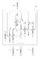
図1に示すように、RCヘリコプタ1は、その機体内に、センサ部2、各種のアクチュエータ3(3a〜3e)、RC信号切替器4、制御計算用CPU5、予測計算用CPU6、RC受信器7を有する。 As shown in FIG. 1, an RC helicopter 1 includes a
アクチュエータ3(3a〜3e)は飛行体の飛行動作を実行するためのロータやブレードのピッチ等の駆動系のアクチュエータである。
RC受信器7はRC送信器8からの操縦信号を受信する。
操縦者がRC送信機8で機体1を操縦する操作を行うと、操縦信号は無線によりRC受信機7へ送られ、電気信号に変換されてアクチュエータ3へ送られ、アクチュエータ3が機体の舵を操作することで飛行する。
以上は一般的なRCヘリコプタと同じ構成要素である。The actuator 3 (3a to 3e) is an actuator of a drive system such as a rotor or blade pitch for executing the flying operation of the flying object.
The RC receiver 7 receives the steering signal from the
When the operator performs an operation of maneuvering the airframe 1 with the
The above are the same components as a general RC helicopter.
本実施の形態のRCヘリコプタ1は、センサ部2、RC信号切替器4、制御計算用CPU5、予測計算用CPU6を搭載している点が、一般的なRCヘリコプタと異なる。
センサ部2はRCヘリコプタ1としての機体の飛行状態を計測する各種センサを示している。具体的には慣性センサ、GPS(Global Positioning System)センサ、回転速度センサ等を搭載している。
RC信号切替器4は、RC受信器7およびアクチュエータ3の信号を分岐する。本例の場合、RC受信器7からの操縦信号と、制御計算用CPU5からの操縦信号が、制御計算用CPU5内で選択されてRC信号切替器4に供給される。RC信号切替器4は、その供給された操縦信号をアクチュエータ3に供給する。The RC helicopter 1 of the present embodiment is different from a general RC helicopter in that a
The
The
制御計算用CPU5は、センサ部2およびRC信号切換器4から送られる情報をもとに各種計算を行う。具体的には制御計算用CPU5は、飛行制御装置としての制御・演算処理を行う。即ち制御計算用CPU5は、人の操縦操作に応じた操縦信号によって飛行動作が制御される手動制御モードの際に、要危険回避状態との判定結果に応じて、自動操縦による操縦信号によって飛行動作が制御される自動制御モードとするモード切替制御を行う。また制御計算用CPU5は、モード切替制御により自動制御モードに切り替えられた状態で危険回避のための飛行を実行させる操縦信号を生成する危険回避制御処理を行う。さらに制御計算用CPU5は、危険回避制御処理による操縦信号に応じた飛行で危険回避が行われたと判定した後に、飛行体を空中待機状態とするための操縦信号を生成する待機飛行制御処理を行う。 The
予測計算用CPU6は各種予測計算を行う。例えばRCヘリコプタ1の飛行が、設定した飛行範囲から逸脱する可能性を予測する計算を行う。
なお、制御計算用CPU5と予測計算用CPU6はひとまとめにしてもよい。また、予測計算用CPU6の搭載場所は必ずしも機体上でなくてもよく、例えばRC送信器8内に搭載して、計算結果の情報を制御計算用CPU5に提供できる構成としてもよい。The
The
<2.制御計算用CPU5のソフトウェア構成>
図2は制御計算用CPU5に搭載するソフトウェア51の構成である。
図2ではソフトウェアとして実現される各機能を仮想的にブロック化して示している。即ち状態計算部52、危険回避制御部53、待機飛行制御部54、モード切替制御部55、信号選択器56である。なお後述する図3、図4もソフトウェアによって実行される機能をブロック化して示している点は同様である。
また、これらのソフトウェア機能がそれぞれハードウェアにより実現されてもよい。<2. Software configuration of
FIG. 2 shows the configuration of the
In FIG. 2, each function realized as software is virtually shown as a block. That is, the
In addition, each of these software functions may be realized by hardware.
図2において、状態計算部52は、センサ部2から送られてくる情報をもとに、機体の現在の姿勢・角速度・位置・速度およびメインロータ回転速度を計算する。
危険回避制御部53は、機体を危険な飛行状態から安全な飛行状態へ復帰させるための制御則の計算部であり、詳細は後述する。
待機飛行制御部54は、機体のホバリング(空中停止)状態を自動的に保つための制御則の計算部である。待機飛行制御部54は、例えば先に挙げた非特許文献3に示された手法を用いて構成することが可能である。In FIG. 2, the
The danger
The standby
モード切替制御部55は、人の操縦操作に応じた操縦信号によって飛行動作が制御される手動制御モードと、制御計算用CPU5が生成する操縦信号によって飛行動作が制御される自動制御モードとを切替制御する。
本例では特に自動制御モードにおいて危険な飛行状態から復帰させる危険回避制御モードと、ホバリングにより空中待機する待機飛行制御モードがある。従ってモード切替制御部55は、手動制御モードと、自動制御モードにおける危険回避制御モードと、同じく自動制御モードにおける待機飛行制御モードとの3つのモードを自動的に選択するモード切替則とされている。詳細は後述する。The mode
In this example, there is a danger avoidance control mode for returning from a dangerous flight state in the automatic control mode, and a standby flight control mode for waiting in the air by hovering. Therefore, the mode
信号選択器56は、モード切替制御部55でのモード選択に基づき、3つの入力信号から1つを選択して出力する信号選択器である。端子56A,56B,56Cは仮想的な端子として示している。端子56Aは、危険回避制御部53によって生成された操縦信号を選択する状態を表している。端子56Bは、待機飛行制御部54によって生成された操縦信号を選択する状態を表している。端子56Cは、RC受信器7で受信した操縦信号を選択する状態を表している。
端子56Cが選択された場合、機体は人間が手動操縦する状態となり、通常はこの状態で操縦訓練が行われる。端子56Aまたは端子56Bが選択された場合、機体は人間の手動操縦を介さず、危険回避制御部53または待機飛行制御部54に内蔵された制御則により自動制御された状態になる。The
When the terminal 56C is selected, the aircraft is in a state where a human is manually maneuvering, and the maneuvering training is normally performed in this state. When the terminal 56A or the terminal 56B is selected, the aircraft is automatically controlled by a control law built in the danger
図3は、危険回避制御部53の詳細である。
状態推定器531において、RCヘリコプタ1の運動を決定する変数のうち直接計測できないものを推定し、制御器532内の各制御器へ渡す。
制御器532には、角速度制御器533、回転速度制御器534、姿勢制御器535、推力制御器536、速度制御器537がある。これらの各制御器(533〜537)は、状態推定器531などからの情報に基づきRCヘリコプタ1の操舵量を決定し、コマンド分配則538にてアクチュエータ指令値に変換して出力する。
目標値計算器539は、RCヘリコプタ1の飛行速度に対する目標値を計算する。FIG. 3 shows details of the danger
In the
The
The
状態推定器531は、RC信号切換器4から送られてくる操舵量の情報{uSWM1,uSWM2,uSWM3,uDIR,uTHR}、および状態計算部52から送られてくる機体の現在の3軸角速度{ωNB}B=[pB qB rB]T、姿勢qNB、速度{VNB}N、メインロータ回転速度Ωの各情報をもとに、下記(数1)のヘリコプタ飛行状態を記述する変数(以下、状態変数と呼ぶ)を算出する。算出のための数式は、例えば非特許文献3に示された手法を用いて構成することが可能である。The

ここで、A0FMR,A1FMR,B1FMRは、それぞれメインブレードフラッピング角の定常成分、縦1次ハーモニック成分、横1次ハーモニック成分である。
A0LMR,A1LMR,B1LMRは、それぞれメインブレードリード・ラグ角の定常成分、縦1次ハーモニック成分、横1次ハーモニック成分である。
A1FMRs,B1FMRsは、それぞれスタブライザブレードフラッピング角の縦・横1次ハーモニック成分である。
dSWM1,dSWM2,dSWM3,dDIRは、それぞれSWM1,SWM2,SWM3,DIRアクチュエータの舵角である。Here, A0FMR , A1FMR , and B1FMR are a steady component, a vertical primary harmonic component, and a horizontal primary harmonic component of the main blade flapping angle, respectively.
A0LMR , A1LMR , and B1LMR are a stationary component, a longitudinal primary harmonic component, and a transverse primary harmonic component of the main blade lead / lag angle, respectively.
A1FMRs and B1FMRs are vertical and horizontal primary harmonic components of the stub riser blade flapping angle, respectively.
dSWM1 , dSWM2 , dSWM3 , and dDIR are the steering angles of SWM1, SWM2, SWM3, and DIR actuators, respectively.
角速度制御器533は次の(数2)により制御入力ua=[ulatulonuDIR]Tを計算する。ulatは左右方向、ulonは前後方向、uDIRはヨー方向の制御入力である。
なお、以下記号Δをつけた変数は、各変数が釣り合い飛行状態でとる値からの差分値であることを示すものである。The
In the following, the variable with the symbol Δ indicates that each variable is a difference value from the value taken in the balanced flight state.
ここで、Δxa0はΔxaの制御開始時の値、{ΔωNBcmd}Bは{ΔωNB}Bに対する目標値である。H0a,F0a,F1a,Gaは制御ゲイン行列であり、一般によく知られた最適制御理論などを用いて定めることが可能である。Here, Δxa0 is a value at the start of control of Δxa, and {ΔωNBcmd }B is a target value for {ΔωNB }B. H0a , F0a , F1a , and Ga are control gain matrices, and can be determined using generally well-known optimal control theory.
回転速度制御器534は(数3)により回転速度の制御入力uTHRを計算する。The
ここで、KpΩ,KiΩは、それぞれ制御ゲインである。Here, KpΩ and KiΩ are control gains, respectively.
推力制御器536は(数4)により推力の制御入力ucoll計算する。The
ここで、TZBcmdは推力目標値のZ軸(機体鉛直方向)成分、TZBtrmは釣り合い飛行状態における推力のZ軸(機体鉛力方向)成分、KpTzは制御ゲインである。Here, TZBcmd is a Z-axis (airframe vertical direction) component of a thrust target value, TZBtrm is a Z-axis (airframe lead force direction) component of thrust in a balanced flight state, and KpTz is a control gain.
姿勢制御器535は、(数5)により{ΔωNBcmd}Bを計算する。The
ここで、qeは後述の速度制御器537で計算される誤差クォータニオン、Kpqは制御ゲイン、qNCは目標の機体姿勢を表すクォータニオン(四元数)、“q”の上に“・”を付したqNCはqNCの時間微分、qNBは現在の機体姿勢を表すクォータニオン(四元数)である。 Here, qe is an error quaternion calculated by a
速度制御器537は、(数6)によりqeを計算する。The
ここで、TBtrmは釣り合い飛行状態における機体の推力を機体座標系で表現したベクトル、gNは重力加速度を地面座標系で表現したベクトル、mは機体の質量、{VNB}Nは機体の現在速度を地面座標系で表現したベクトル、{VNBcmd}Nは{VNB}Nに対する目標値、KpVは制御ゲインである。Here, TBtrm is a vector expressing the thrust of the aircraft in a balanced flight state in the aircraft coordinate system, gN is a vector expressing the gravitational acceleration in the ground coordinate system, m is the mass of the aircraft, and {VNB }N is the aircraft {VNBcmd }N is a target value for {VNB }N , and KpV is a control gain.
<3.予測計算用CPU6のソフトウェア構成>
図4は、予測計算用CPU6に搭載するソフトウェア61の構成である。
状態推定器62、制御器63、コマンド分配則64、目標値計算器66には、それぞれ制御計算用CPU5の状態推定器531、制御器532、コマンド分配則538、目標値計算器539と同じソフトウェアが入っている。<3. Software Configuration of
FIG. 4 shows the configuration of the
The
機体運動モデル65は、ヘリコプタの運動を数式で記述したものが含まれており、ヘリコプタの運動を計算上で再現することが出来る。
機体運動モデル65は、一定時間おきに制御計算用CPU5の状態推定器531から出力される情報により初期化する。その後、この初期化した状態においてRCヘリコプタ1の機体が予め設定した飛行範囲を出そうになったと仮定して、機体運動モデル65が予め設定した飛行範囲を出ないように制御する計算機シミュレーションを数秒先まで行う。このシミュレーションは状態推定器62、制御器63、コマンド分配則64、目標値計算器66を用いて行う。
このシミュレーションの間に、機体運動モデル65が予め設定した飛行範囲の境界線に触れた場合、実際のRCヘリコプタ1の機体もこの飛行範囲の境界線に触れる、つまり、飛行範囲を出るおそれがあると判断し、ON/OFF判定器67はON信号を出力する。それ以外の場合はON/OFF判定器67はOFF信号を出力する。The
The
During this simulation, if the
<4.モード切替処理>
図5により、モード切替制御部55による制御モードの切り替え処理を含む制御計算用CPU5の処理を説明する。
手動操縦による操縦訓練を開始した時点では、モード切替制御部55はステップS101で信号選択器56の端子56Cを選択する。即ち手動制御モードとして、RC受信器7で受信した操縦信号を選択する。従って、信号選択器56からRC信号切替器4には、RC送信器8での人の操作に応じた操縦信号が供給され、これがアクチュエータ3に供給される。<4. Mode switching process>
With reference to FIG. 5, processing of the
At the time when the steering training by manual steering is started, the mode
手動制御モードとしている間、モード切替制御部55は、ステップS102で予測計算用CPU6からのON信号を監視している。ON信号は、上述の通り、機体運動モデル65によりRCヘリコプタ1が飛行範囲を出るおそれがあると判断されたときに、ON/OFF判定器67が出力する信号である。従ってステップS102の判断は、飛行範囲の逸脱という危険が予測されることで、要危険回避状態となったか否かを判断する処理となる。 While in the manual control mode, the mode
また手動制御モードとしている間、モード切替制御部55はステップS103で、状態計算部52からの情報として得られる現在の機体の姿勢・速度が設定した閾値より大きいか否かを監視している。このステップS103の判断は、現在の機体の姿勢や速度が、墜落又は制御不能に至ることが予測される状態となっているか否かという点で、要危険回避状態であるか否かを判断する処理となる。 While in the manual control mode, the mode
ステップS102,S103のいずれかで要危険回避状態であると判断された場合、モード切替制御部55はステップS104で、信号選択器56の端子56Aを選択する。即ち自動制御モードとして、危険回避制御部53が図3のソフトウェアにより生成した操縦信号を選択する。従って、信号選択器56からRC信号切替器4には、危険回避制御部53が生成した操縦信号が供給され、これがアクチュエータ3に供給される。
これによりRCヘリコプタ1は自動的に手動操作が無効とされ、自動操縦により危険回避が行われる。例えば姿勢の安定化、速度の適正化を行い、機体の飛行安全を確保する。If it is determined in any of steps S102 and S103 that the danger avoidance state is required, the mode
As a result, manual operation of the RC helicopter 1 is automatically invalidated, and danger avoidance is performed by automatic steering. For example, it stabilizes the attitude and optimizes the speed to ensure the flight safety of the aircraft.
そして、ステップS105で機体の現在の姿勢・速度の両方がある閾値以下に収束したと確認された時点で、モード切替制御部55はステップS106において信号選択器56の端子56Bを選択する。即ち引き続き自動制御モードとして、待機飛行制御部54が生成した操縦信号を選択する。従って、信号選択器56からRC信号切替器4には、待機飛行制御部54が生成した操縦信号が供給され、これがアクチュエータ3に供給される。待機飛行制御部54が生成する操縦信号は、例えばホバリング状態を維持する操縦信号である。なお、飛行範囲の逸脱の場合も想定するため、待機飛行制御部54による操縦信号は、所定の飛行位置まで戻る飛行を行い、当該所定の位置においてホバリングを行うような操縦信号であってもよい。これらのような操縦信号によりRCヘリコプタ1は空中でホバリング状態で待機することになる。 When it is confirmed in step S105 that both the current attitude and speed of the aircraft have converged below a certain threshold, the mode
待機状態においては、モード切替制御部55はステップS107で操縦者の操作に基づく手動制御モードへの復帰の要求信号を待つ。
操縦者は、RC送信器8を操作して、訓練再開の要求信号をRCヘリコプタ1に送信できる。モード切替制御部55は要求信号を受けることに応じて、ステップS101に戻り、信号選択器56を端子56C、即ち手動制御モードに戻す。これにより手動操縦による操縦訓練が再開できることになる。In the standby state, the mode
The operator can operate the
図6は図5の変形例である。図6において図5と異なるのはステップS106,S107の間にステップS110を設けている点であるため、この処理についてのみ説明する。
モード切替制御部55はステップS106において、待機飛行制御部54が生成した操縦信号を選択する。この場合の操縦信号は、所定の飛行位置まで戻る飛行を行い、当該所定の位置においてホバリングを行うような一連の操縦を行う操縦信号であるとする。
ステップS110では、この操縦信号に応じた飛行の過程で、状態計算部52から提供される現在位置情報を監視し、所定の飛行位置(目標位置)にまで戻ったか否かを判断している。そして目標位置まで戻るまでは、ステップS107に進まない。
従って、目標位置に戻った後において、ステップS107の要求信号を受け付け、訓練を再開可能とするものである。FIG. 6 is a modification of FIG. FIG. 6 differs from FIG. 5 in that step S110 is provided between steps S106 and S107, and only this process will be described.
In step S106, the mode
In step S110, the current position information provided from the
Therefore, after returning to the target position, the request signal in step S107 is accepted and the training can be resumed.
<5.まとめ>
以上の実施の形態のRCヘリコプタ1は、制御計算用CPU5として飛行制御装置を備えている。制御計算用CPU5(飛行制御装置)は、人の操縦操作に応じた操縦信号によって飛行動作が制御される手動制御モードの際に、要危険回避状態との判定結果に応じて、自動操縦による操縦信号によって飛行動作が制御される自動制御モードに切り替える制御を行うモード切替制御部55を有する。
また制御計算用CPU5はモード切替制御部55により自動制御モードに切り替えられた状態で、危険回避のための飛行を実行させる操縦信号を生成する危険回避制御部53と、危険回避制御部53による操縦信号に応じた飛行で危険回避が行われたと判定された後に、飛行体を空中待機状態とするための操縦信号を生成する待機飛行制御部54を備えている。
即ち飛行体の操縦訓練等のために、手動制御モードではマニュアル操縦として人が飛行体の飛行を制御(操縦)できるようにする。そしてその際に要危険回避状態であると判定された場合は、自動制御モードとして自動操縦に切り替えて、危険回避のための飛行動作制御を行う。さらにその後、飛行体が空中待機するように制御する。
このように人の操縦による飛行時に、危険が予測され危険回避が必要と判定された場合、自動操縦によって危険回避が行われるため、操縦訓練などにおいて事故の発生を防止でき、非習熟者による操縦においても安全性を担保できる。
また危険回避後において空中待機させることで、安全を確保した状態で引き続き訓練飛行を継続でき、効率的な訓練が可能となる。<5. Summary>
The RC helicopter 1 of the above embodiment includes a flight control device as the
Further, the
That is, for the purpose of training the flying object, etc., in the manual control mode, a person can control (maneuver) the flight of the flying object as a manual operation. At this time, if it is determined that the danger avoidance state is required, the automatic control mode is switched to automatic piloting, and flight operation control for danger avoidance is performed. After that, control is performed so that the flying object waits in the air.
In this way, when it is determined that danger is predicted and it is necessary to avoid danger during flight by maneuvering, risk avoidance is performed by automatic maneuvering, so accidents can be prevented during maneuvering training, etc. Can also ensure safety.
Also, by waiting in the air after avoiding danger, training flight can be continued with safety ensured, and efficient training becomes possible.
また実施の形態では、モード切替制御部55は、待機飛行制御部54による操縦信号によって飛行が行われている際において、外部の操縦装置(RC送信器8)からの要求信号を認識することに応じて、手動制御モードに切り替える制御を行うようにしている(図5のS107→S101)。
これにより安全な状態になった後に、操縦訓練等のための手動操縦に切り替えることができる。In the embodiment, the mode
Thus, after a safe state is reached, it is possible to switch to manual operation for operation training or the like.
また図6で説明したように、モード切替制御部55は、待機飛行制御部54による操縦信号によって飛行体が予め設定した特定位置に到達した後においてのみ要求信号を受け付けるようにしてもよい。即ち危険回避後において待機飛行制御部54による制御が行われているときに、無条件で要求信号を受け付けて手動制御モードに復帰させるのではなく、特定の飛行位置に戻ることを条件として手動制御モードに復帰できるようにする。このように特定の飛行位置に戻るまでは手動制御モードに復帰させないようにすることで、より飛行範囲の逸脱に対する安全性を高めることができる。 In addition, as described with reference to FIG. 6, the mode
また制御計算用CPU5は、RCヘリコプタ1に搭載されているセンサ部2の検出信号から得られる飛行体の姿勢又は速度を、設定閾値と比較して、要危険回避状態か否かを判定する(S102)。
これにより、例えば未熟な操縦による飛行体の墜落事故等の危険状態に至ることを予測でき、自動制御モードによる危険回避制御が可能となる。Further, the
As a result, for example, it is possible to predict a dangerous state such as an aircraft crash due to immature maneuvering, and risk avoidance control in the automatic control mode becomes possible.
また実施の形態の構成では、RCヘリコプタ1が設定した飛行範囲から逸脱する可能性を予測した予測計算結果から要危険回避状態か否かを判定する予測計算部(予測計算用CPU6)を備えている。
RCヘリコプタ1の飛行位置が、あらかじめ設定した飛行範囲を超えてしまうことで危険状態に至ることを予測する計算結果により要危険回避状態であるか否かを判定できる。これにより、例えば未熟な操縦による飛行範囲逸脱を回避することが可能となる。Further, the configuration of the embodiment includes a prediction calculation unit (a
Whether or not the flight position of the RC helicopter 1 is in a dangerous avoidance state can be determined based on a calculation result that predicts that a dangerous state is reached when the flight position exceeds a preset flight range. Thereby, for example, it is possible to avoid a flight range deviation due to immature maneuvering.
実施の形態のRCヘリコプタ1は、以上のような飛行制御装置(制御計算用CPU5、予測計算用CPU6)とともに、RCヘリコプタ1の飛行状態又は飛行位置を検出するセンサ部2と、飛行動作を実現するためのアクチュエータ5と、アクチュエータに対して、人の操縦操作に応じた操縦信号と、自動操縦による操縦信号を選択的に供給する切替器(4,56)とを備える。
このような飛行体は、操縦訓練に適した飛行体として好適である。即ち、実機を使って、しかも非習熟者でも危険がない訓練が可能となる。The RC helicopter 1 according to the embodiment realizes the flight operation with the
Such an aircraft is suitable as an aircraft suitable for pilot training. That is, it is possible to perform training using a real machine without danger even for non-skilled persons.
実施の形態のRCヘリコプタ1のシステムによれば、無人ヘリコプタの操縦訓練において、フライトシミュレータではなく実際の機体を用いながら、熟練操縦者の支援を必要としない操縦訓練が可能になる。搭載したセンサ部2や飛行制御装置(制御計算用CPU5)が熟練操縦者の代わりとなる。そのため、熟練操縦者が身近にいない環境でも実際の機体を用いた訓練が可能になる。
また、被訓練者が自分のペースで訓練を行うことができ、自身の都合や上達度合いに応じた柔軟かつ効率的な訓練スケジュールの設定が可能になる。
また、実施の形態のRCヘリコプタ1のシステムによれば、操縦訓練時の安全性が飛躍的に高まる。従来技術では、操縦訓練中に姿勢が崩れた際、操縦者の操作により自動的に元に戻す機能を持つものはあったが、速度の抑制はできず、所定の飛行範囲の外へ出る可能性があり、また、危険な状態であるか否かはあくまで人間が判断していたため、復帰操作が遅れると事故に至る危険性があった。実施の形態のRCヘリコプタ1のシステムによれば、姿勢の復帰のみでなく速度の抑制を行って完全なホバリング状態へ戻すことができ、機体運動の予測に基づいて機体を所定の飛行範囲から出ることを防止し、危険な状態であるか否かの判断を自動で行って安全を確保することができるので、操縦訓練中の事故を大幅に減らせるものと期待できる。
これにより、操縦訓練の期間短縮やコスト低減に寄与し、また、今後需要が増えると見込まれる無人ヘリコプタ操縦者の効率的な育成に寄与する。
それに加えて、機体喪失や人身事故の危険を最小限にできることで、修理・賠償コストの低減はもちろん、飛行安全向上にも寄与し、無人ヘリコプタ操縦者育成・運用企業が果たすべき社会的責務の遂行にも貢献し、無人ヘリコプタ市場の拡大にも貢献するものと見込まれる。According to the RC helicopter 1 system of the embodiment, in the unmanned helicopter maneuvering training, the maneuvering training which does not require the assistance of the skilled maneuverer is possible while using the actual aircraft instead of the flight simulator. The mounted
Moreover, the trainee can train at his / her own pace, and a flexible and efficient training schedule can be set according to his / her convenience and progress.
Moreover, according to the system of RC helicopter 1 of embodiment, the safety | security at the time of steering training increases greatly. In the prior art, there was a function that automatically returned to the original position by the operator's operation when the posture collapsed during pilot training, but the speed could not be suppressed and it was possible to go out of the predetermined flight range In addition, since human beings have determined whether or not it is in a dangerous state, there is a risk of an accident if the return operation is delayed. According to the system of the RC helicopter 1 of the embodiment, not only the attitude return but also the speed can be controlled to return to the complete hovering state, and the aircraft exits the predetermined flight range based on the prediction of the aircraft motion It is possible to prevent accidents and automatically determine whether or not the vehicle is in a dangerous state, so that safety can be ensured. Therefore, it is expected that accidents during operation training can be greatly reduced.
As a result, it contributes to shortening the duration of pilot training and cost reduction, and also contributes to the efficient training of unmanned helicopter pilots whose demand is expected to increase in the future.
In addition, by minimizing the risk of airframe loss and personal injury, it will not only reduce repair and compensation costs, but will also improve flight safety, and fulfill the social responsibilities that unmanned helicopter pilot training and operation companies should fulfill Is expected to contribute to the expansion of the unmanned helicopter market.
本発明は、上述の実施の形態の構成に限らず、多様な変形例が考えられる。
例えば図1、図2の構成例では、RC送信器8で受信した操縦信号をRC信号切替器4を介して制御計算用CPU5に入力し、制御計算用CPU5内(信号選択器56)で操縦信号を選択する構成としたが、RC信号切替器4における選択動作により、手動制御モードと自動制御モードでの操縦信号の選択が行われてもよい。
また図5,図6の処理例ではステップS102の飛行範囲の逸脱予測の監視と、ステップS103の姿勢・速度の監視の両方を行って、いずれかに該当の場合に要危険回避状態としてステップS104の危険回避制御を行うものとしたが、ステップS102,S103のいずれか一方のみの監視処理を行うものであってもよい。
また、実施の形態はRCヘリコプタ1の例で説明したが、本発明は、RCヘリコプタ以外の飛行体にも適用できることは当然である。The present invention is not limited to the configuration of the above-described embodiment, and various modifications can be considered.
For example, in the configuration example of FIGS. 1 and 2, the steering signal received by the
5 and 6, both the flight range deviation prediction monitoring in step S102 and the attitude / speed monitoring in step S103 are performed, and in either case, the danger avoidance state is set as step S104. However, the monitoring process of only one of steps S102 and S103 may be performed.
Moreover, although embodiment demonstrated the example of RC helicopter 1, it is natural that this invention is applicable also to air vehicles other than RC helicopter.
1 RCヘリコプタ1、2 センサ部、3 アクチュエータ、4 RC信号切替器、5 制御計算用CPU、6 予測計算用CPU、7 RC受信器、8 RC送信器、52 状態計算部、53 危険回避制御部、54 待機飛行制御部、55 モード切替制御部、56 信号選択器 DESCRIPTION OF SYMBOLS 1
Claims (6)
Translated fromJapanese人の操縦操作に応じた操縦信号によって飛行動作が制御される手動制御モードの際において、飛行体に搭載されているセンサ部の検出信号から得られる飛行体の姿勢及び速度を設定閾値と比較して要危険回避状態となっていると判定した場合に、自動操縦による操縦信号によって飛行動作が制御される自動制御モードに切り替える制御を行うモード切替制御部と、
前記モード切替制御部により自動制御モードに切り替えられた状態で、危険回避のための飛行を実行させる操縦信号を生成する危険回避制御部と、
前記危険回避制御部による操縦信号に応じた飛行で危険回避が行われたと判定された後に、飛行体を空中停止による待機状態とするための操縦信号を生成する待機飛行制御部と、を備えた
飛行制御装置。A flight control device for a flying object having a rotor for flight,
In manual control mode, where flight operations are controlled by maneuvering signals according to maneuvering operations,the attitude and speed of the flying object obtained from the detection signal of the sensor unit mounted on the flying object are compared with the set threshold. A mode switching control unit that performs control to switch to an automatic control mode in which the flight operation is controlled by a control signal by automatic controlwhen it is determined that it is in a danger avoidance state ,
A danger avoidance control unit that generates a control signal for executing a flight for danger avoidance in a state where the mode switching control unit is switched to the automatic control mode;
A standby flight control unit that generates a steering signal for setting the flying object ina standby stateby stopping in the air after it is determined that the danger avoidance has been performed in the flight according to the steering signal by the danger avoidance control unit; Flight control device.
請求項1に記載の飛行制御装置。The mode switching control unit performs control to switch to a manual control mode in response to recognizing a request signal from an external control device when a flight is performed by a control signal from the standby flight control unit. Item 4. The flight control device according to item 1.
請求項2に記載の飛行制御装置。The flight control device according to claim 2, wherein the mode switching control unit accepts the request signal only after reaching the specific position set by the flying object based on the steering signal from the standby flight control unit.
前記危険回避制御部は前記予測計算部から要危険回避の判定を取得した場合に飛行範囲からの逸脱を防止するための飛行を実行させる操縦信号を生成する機能を備え、
飛行範囲からの逸脱を防止するための飛行を実行させる操縦信号に応じた飛行で飛行範囲からの逸脱の防止が行われたと判定された後に、前記待機飛行制御部により飛行体を空中停止による待機状態とするための操縦信号を生成する
請求項1乃至請求項3のいずれかに記載の飛行制御装置。A prediction calculation unit that determines whether or not the vehicle is in a danger avoidance state from a prediction calculation result that predicts the possibility that the flying object deviates from the set flight range;
The danger avoidance control unit has a function of generating a control signal for executing a flight for preventing a departure from a flight range when a risk avoidance determination is obtained from the prediction calculation unit,
After it is determined that the departure from the flight range has been prevented in the flight according to the control signal for executing the flight to prevent the departure from the flight range, the standby flight control unit waits for the flying object to stop in the air Generate a steering signal to enter the state
The flight control apparatus according toany one of claims 1 to 3 .
人の操縦操作に応じた操縦信号によって飛行動作が制御される手動制御モードの際において、飛行体に搭載されているセンサ部の検出信号から得られる飛行体の姿勢及び速度を設定閾値と比較して要危険回避状態となっていると判定した場合に、自動操縦による操縦信号によって飛行動作が制御される自動制御モードに切り替える制御を行い、
自動制御モードに切り替えられた状態で、危険回避のための飛行を実行させる操縦信号を生成し、
前記危険回避のための飛行を実行させる操縦信号に応じた飛行で危険回避が行われたと判定された後に、飛行体を空中停止による待機状態とするための操縦信号を生成する
飛行制御方法。A flight control method for an aircraft having a rotor for flight,
In manual control mode, where flight operations are controlled by maneuvering signals according to maneuvering operations,the attitude and speed of the flying object obtained from the detection signal of the sensor unit mounted on the flying object are compared with the set threshold. Te when determined that the main risk aversion state, performs control to switch to automatic control mode in which the flight operation by flight signal by autopilot is controlled,
In the state that is switched to the automatic control mode, generate a steering signal that causes the flight to avoid danger,
Flight control method for generating a steering signal to the standby state after said risk avoidance flight in accordance with the maneuver signal for executing the flight for avoiding dangeris judged to be made,according to hover the aircraft.
飛行体の飛行状態又は飛行位置を検出するセンサ部と、
飛行動作を実現するための1又は複数のアクチュエータと、
前記アクチュエータに対して、人の操縦操作に応じた操縦信号と、自動操縦による操縦信号を選択的に供給する切替器と、
飛行制御装置と、を備え、
前記飛行制御装置は、
人の操縦操作に応じた操縦信号によって飛行動作が制御される手動制御モードの際において、飛行体に搭載されているセンサ部の検出信号から得られる飛行体の姿勢及び速度を設定閾値と比較して要危険回避状態となっていると判定した場合に、自動操縦による操縦信号によって飛行動作が制御される自動制御モードに切り替える制御を行うモード切替制御部と、
前記モード切替制御部により自動制御モードに切り替えられた状態で、危険回避のための飛行を実行させる操縦信号を生成する危険回避制御部と、
前記危険回避制御部による操縦信号に応じた飛行で危険回避が行われたと判定された後に、飛行体を空中停止による待機状態とするための操縦信号を生成する待機飛行制御部と、を備えている
飛行体。A flying object having a rotor for flight,
A sensor unit for detecting a flight state or a flight position of the flying object;
One or more actuators for realizing the flight motion;
A switch for selectively supplying a steering signal according to a maneuvering operation of a person and a steering signal by automatic piloting to the actuator,
A flight control device,
The flight control device includes:
Oite during a manual control mode flight operation is controlled by a steering signal corresponding to the steering manipulation of ahuman, the attitude and set a speed threshold flight body obtained from the detection signal of the sensor portion mounted on aircraft Amode switching control unit that performs control to switch to anautomatic control mode in which a flight operation is controlled by a steering signal by automatic pilotingwhen it is determined that it is in a danger avoidance state in comparison;
Adanger avoidance control unit that generates a control signal for executing a flight for danger avoidance in a state wherethemode switching control unit is switched to the automatic control mode;
After risk aversion flight in accordance with the steering signal fromthe danger avoidance control unit it is determined to have been made,provided with a standby flight control unit for generating a steering signal to the aircraft in astandby stateby hovering aircraftit is.
Priority Applications (1)
| Application Number | Priority Date | Filing Date | Title |
|---|---|---|---|
| JP2015189740AJP6600213B2 (en) | 2015-09-28 | 2015-09-28 | Flight control device, flight control method, flying object |
Applications Claiming Priority (1)
| Application Number | Priority Date | Filing Date | Title |
|---|---|---|---|
| JP2015189740AJP6600213B2 (en) | 2015-09-28 | 2015-09-28 | Flight control device, flight control method, flying object |
Publications (2)
| Publication Number | Publication Date |
|---|---|
| JP2017065297A JP2017065297A (en) | 2017-04-06 |
| JP6600213B2true JP6600213B2 (en) | 2019-10-30 |
Family
ID=58491452
Family Applications (1)
| Application Number | Title | Priority Date | Filing Date |
|---|---|---|---|
| JP2015189740AActiveJP6600213B2 (en) | 2015-09-28 | 2015-09-28 | Flight control device, flight control method, flying object |
Country Status (1)
| Country | Link |
|---|---|
| JP (1) | JP6600213B2 (en) |
Families Citing this family (7)
| Publication number | Priority date | Publication date | Assignee | Title |
|---|---|---|---|---|
| ES2943122T3 (en)* | 2017-06-29 | 2023-06-09 | Boeing Co | Method and system for autonomously operating an aircraft |
| JP6547109B2 (en)* | 2017-07-04 | 2019-07-24 | 株式会社プロドローン | Flight control device and unmanned aerial vehicle equipped with the same |
| WO2019054029A1 (en) | 2017-09-15 | 2019-03-21 | 株式会社Nttドコモ | Flight control device and flight control system |
| WO2019159232A1 (en)* | 2018-02-13 | 2019-08-22 | 楽天株式会社 | Unmanned air vehicle control system, unmanned air vehicle control method, and program |
| JP6663449B2 (en) | 2018-03-13 | 2020-03-11 | 株式会社Subaru | Flight training support system |
| WO2019225762A1 (en)* | 2018-05-25 | 2019-11-28 | 株式会社ナイルワークス | Drone system, drone, controller, method for controlling drone system, and control program of drone system |
| CN113879057B (en)* | 2021-11-17 | 2023-11-03 | 广东汇天航空航天科技有限公司 | Control processing method and control system of aerocar and aerocar |
Family Cites Families (10)
| Publication number | Priority date | Publication date | Assignee | Title |
|---|---|---|---|---|
| JP3297830B2 (en)* | 1994-06-29 | 2002-07-02 | ヤンマー農機株式会社 | Helicopter remote control |
| US7219861B1 (en)* | 2000-07-06 | 2007-05-22 | Spirit International, Inc. | Guidance system for radio-controlled aircraft |
| US6493609B2 (en)* | 2001-04-27 | 2002-12-10 | Lockheed Martin Corporation | Automatic flight envelope protection for uninhabited air vehicles |
| JP2003127994A (en)* | 2001-10-24 | 2003-05-08 | Kansai Electric Power Co Inc:The | Unmanned flying object control system |
| US6711477B1 (en)* | 2002-08-29 | 2004-03-23 | Lockheed Corp | Automatic flight envelope protection for uninhabited air vehicles: method for determining point in flight envelope |
| JP4141860B2 (en)* | 2003-02-26 | 2008-08-27 | 健蔵 野波 | Autonomous control device and program for small unmanned helicopter |
| JP4304009B2 (en)* | 2003-06-04 | 2009-07-29 | 富士重工業株式会社 | Unmanned aircraft control system |
| FR2927262B1 (en)* | 2008-02-13 | 2014-11-28 | Parrot | METHOD FOR CONTROLLING A ROTARY WING DRONE |
| CN102053619B (en)* | 2009-11-06 | 2012-11-21 | 北京理工大学 | Method for switching automatic flight mode and manual remotely-controlled flight mode of miniature unmanned helicopter |
| US9056667B2 (en)* | 2013-05-22 | 2015-06-16 | Horizon Hobby, LLC | Flight modes and protection envelopes based on inertial attitude estimates for radio-controlled airplanes |
- 2015
- 2015-09-28JPJP2015189740Apatent/JP6600213B2/enactiveActive
Also Published As
| Publication number | Publication date |
|---|---|
| JP2017065297A (en) | 2017-04-06 |
Similar Documents
| Publication | Publication Date | Title |
|---|---|---|
| JP6600213B2 (en) | Flight control device, flight control method, flying object | |
| US12296952B2 (en) | Long line loiter apparatus, system, and method | |
| Naldi et al. | Design and experimental validation of a nonlinear control law for a ducted-fan miniature aerial vehicle | |
| Cabecinhas et al. | Robust landing and sliding maneuver hybrid controller for a quadrotor vehicle | |
| JP4141860B2 (en) | Autonomous control device and program for small unmanned helicopter | |
| JP4133435B2 (en) | Autonomous control method for small unmanned helicopter | |
| US7630798B2 (en) | Heading reference command and control algorithm systems and methods for aircraft turn-to-target maneuvers | |
| JP2019513610A (en) | Airline crew automation system and method | |
| Soneson et al. | Simulation testing of advanced response types for ship-based rotorcraft | |
| Bourquardez et al. | Visual servoing of an airplane for auto-landing | |
| US11992444B1 (en) | Apparatus, system, and method to control torque or lateral thrust applied to a load suspended on a suspension cable | |
| Jeong et al. | A quad-rotor system for driving and flying missions by tilting mechanism of rotors: From design to control | |
| Acuna et al. | Vision-based UAV landing on a moving platform in GPS denied environments using motion prediction | |
| JP5493103B2 (en) | Simple manual flight control system for unmanned flying vehicles | |
| KR20240011797A (en) | Long line loiter apparatus, system and method | |
| Vitzilaios et al. | An experimental test bed for small unmanned helicopters | |
| Xie et al. | Cooperative transport of a suspended payload via two aerial robots with inertial sensing | |
| JP2017191225A (en) | Steering training system | |
| Foster | Autonomous guidance algorithms for NASA learn-to-fly technology development | |
| US12371306B2 (en) | Apparatus, system, and method to control torque or lateral thrust applied to a load suspended on a suspension cable | |
| KR20200041142A (en) | Remote controller device having feedback control of unmanned aerial vehicle | |
| Bulka | Control and obstacle avoidance for agile fixed-wing aircraft | |
| Rifaï et al. | Haptic-based bilateral teleoperation of underactuated unmanned aerial vehicles | |
| Munoz et al. | Observer-control scheme for autonomous navigation: Flight tests validation in a quadrotor vehicle | |
| Dobrokhodov et al. | Flight validation of metrics driven L1 adaptive control |
Legal Events
| Date | Code | Title | Description |
|---|---|---|---|
| A621 | Written request for application examination | Free format text:JAPANESE INTERMEDIATE CODE: A621 Effective date:20180214 | |
| A521 | Request for written amendment filed | Free format text:JAPANESE INTERMEDIATE CODE: A821 Effective date:20180214 | |
| A977 | Report on retrieval | Free format text:JAPANESE INTERMEDIATE CODE: A971007 Effective date:20181214 | |
| A131 | Notification of reasons for refusal | Free format text:JAPANESE INTERMEDIATE CODE: A131 Effective date:20181225 | |
| A601 | Written request for extension of time | Free format text:JAPANESE INTERMEDIATE CODE: A601 Effective date:20190220 | |
| A521 | Request for written amendment filed | Free format text:JAPANESE INTERMEDIATE CODE: A523 Effective date:20190405 | |
| TRDD | Decision of grant or rejection written | ||
| A01 | Written decision to grant a patent or to grant a registration (utility model) | Free format text:JAPANESE INTERMEDIATE CODE: A01 Effective date:20190924 | |
| A61 | First payment of annual fees (during grant procedure) | Free format text:JAPANESE INTERMEDIATE CODE: A61 Effective date:20191004 | |
| R150 | Certificate of patent or registration of utility model | Ref document number:6600213 Country of ref document:JP Free format text:JAPANESE INTERMEDIATE CODE: R150 | |
| R250 | Receipt of annual fees | Free format text:JAPANESE INTERMEDIATE CODE: R250 | |
| R250 | Receipt of annual fees | Free format text:JAPANESE INTERMEDIATE CODE: R250 | |
| R250 | Receipt of annual fees | Free format text:JAPANESE INTERMEDIATE CODE: R250 | |
| R250 | Receipt of annual fees | Free format text:JAPANESE INTERMEDIATE CODE: R250 |