JP6596470B2 - Medical treatment device wire and guide wire - Google Patents
Medical treatment device wire and guide wireDownload PDFInfo
- Publication number
- JP6596470B2 JP6596470B2JP2017140985AJP2017140985AJP6596470B2JP 6596470 B2JP6596470 B2JP 6596470B2JP 2017140985 AJP2017140985 AJP 2017140985AJP 2017140985 AJP2017140985 AJP 2017140985AJP 6596470 B2JP6596470 B2JP 6596470B2
- Authority
- JP
- Japan
- Prior art keywords
- wire
- core
- cross
- measurement point
- medical treatment
- Prior art date
- Legal status (The legal status is an assumption and is not a legal conclusion. Google has not performed a legal analysis and makes no representation as to the accuracy of the status listed.)
- Active
Links
Images


Classifications
- B—PERFORMING OPERATIONS; TRANSPORTING
- B21—MECHANICAL METAL-WORKING WITHOUT ESSENTIALLY REMOVING MATERIAL; PUNCHING METAL
- B21C—MANUFACTURE OF METAL SHEETS, WIRE, RODS, TUBES, PROFILES OR LIKE SEMI-MANUFACTURED PRODUCTS OTHERWISE THAN BY ROLLING; AUXILIARY OPERATIONS USED IN CONNECTION WITH METAL-WORKING WITHOUT ESSENTIALLY REMOVING MATERIAL
- B21C19/00—Devices for straightening wire or like work combined with or specially adapted for use in connection with drawing or winding machines or apparatus
- A—HUMAN NECESSITIES
- A61—MEDICAL OR VETERINARY SCIENCE; HYGIENE
- A61M—DEVICES FOR INTRODUCING MEDIA INTO, OR ONTO, THE BODY; DEVICES FOR TRANSDUCING BODY MEDIA OR FOR TAKING MEDIA FROM THE BODY; DEVICES FOR PRODUCING OR ENDING SLEEP OR STUPOR
- A61M25/00—Catheters; Hollow probes
- A61M25/01—Introducing, guiding, advancing, emplacing or holding catheters
- A61M25/09—Guide wires
- A—HUMAN NECESSITIES
- A61—MEDICAL OR VETERINARY SCIENCE; HYGIENE
- A61L—METHODS OR APPARATUS FOR STERILISING MATERIALS OR OBJECTS IN GENERAL; DISINFECTION, STERILISATION OR DEODORISATION OF AIR; CHEMICAL ASPECTS OF BANDAGES, DRESSINGS, ABSORBENT PADS OR SURGICAL ARTICLES; MATERIALS FOR BANDAGES, DRESSINGS, ABSORBENT PADS OR SURGICAL ARTICLES
- A61L31/00—Materials for other surgical articles, e.g. stents, stent-grafts, shunts, surgical drapes, guide wires, materials for adhesion prevention, occluding devices, surgical gloves, tissue fixation devices
- A61L31/02—Inorganic materials
- A61L31/022—Metals or alloys
- A—HUMAN NECESSITIES
- A61—MEDICAL OR VETERINARY SCIENCE; HYGIENE
- A61L—METHODS OR APPARATUS FOR STERILISING MATERIALS OR OBJECTS IN GENERAL; DISINFECTION, STERILISATION OR DEODORISATION OF AIR; CHEMICAL ASPECTS OF BANDAGES, DRESSINGS, ABSORBENT PADS OR SURGICAL ARTICLES; MATERIALS FOR BANDAGES, DRESSINGS, ABSORBENT PADS OR SURGICAL ARTICLES
- A61L31/00—Materials for other surgical articles, e.g. stents, stent-grafts, shunts, surgical drapes, guide wires, materials for adhesion prevention, occluding devices, surgical gloves, tissue fixation devices
- A61L31/14—Materials characterised by their function or physical properties, e.g. injectable or lubricating compositions, shape-memory materials, surface modified materials
- B—PERFORMING OPERATIONS; TRANSPORTING
- B21—MECHANICAL METAL-WORKING WITHOUT ESSENTIALLY REMOVING MATERIAL; PUNCHING METAL
- B21C—MANUFACTURE OF METAL SHEETS, WIRE, RODS, TUBES, PROFILES OR LIKE SEMI-MANUFACTURED PRODUCTS OTHERWISE THAN BY ROLLING; AUXILIARY OPERATIONS USED IN CONNECTION WITH METAL-WORKING WITHOUT ESSENTIALLY REMOVING MATERIAL
- B21C1/00—Manufacture of metal sheets, wire, rods, tubes or like semi-manufactured products by drawing
- B21C1/02—Drawing metal wire or like flexible metallic material by drawing machines or apparatus in which the drawing action is effected by drums
- B21C1/04—Drawing metal wire or like flexible metallic material by drawing machines or apparatus in which the drawing action is effected by drums with two or more dies operating in series
- C—CHEMISTRY; METALLURGY
- C22—METALLURGY; FERROUS OR NON-FERROUS ALLOYS; TREATMENT OF ALLOYS OR NON-FERROUS METALS
- C22C—ALLOYS
- C22C38/00—Ferrous alloys, e.g. steel alloys
- A—HUMAN NECESSITIES
- A61—MEDICAL OR VETERINARY SCIENCE; HYGIENE
- A61M—DEVICES FOR INTRODUCING MEDIA INTO, OR ONTO, THE BODY; DEVICES FOR TRANSDUCING BODY MEDIA OR FOR TAKING MEDIA FROM THE BODY; DEVICES FOR PRODUCING OR ENDING SLEEP OR STUPOR
- A61M25/00—Catheters; Hollow probes
- A61M25/01—Introducing, guiding, advancing, emplacing or holding catheters
- A61M25/09—Guide wires
- A61M2025/09058—Basic structures of guide wires
- A61M2025/09075—Basic structures of guide wires having a core without a coil possibly combined with a sheath
- A—HUMAN NECESSITIES
- A61—MEDICAL OR VETERINARY SCIENCE; HYGIENE
- A61M—DEVICES FOR INTRODUCING MEDIA INTO, OR ONTO, THE BODY; DEVICES FOR TRANSDUCING BODY MEDIA OR FOR TAKING MEDIA FROM THE BODY; DEVICES FOR PRODUCING OR ENDING SLEEP OR STUPOR
- A61M25/00—Catheters; Hollow probes
- A61M25/01—Introducing, guiding, advancing, emplacing or holding catheters
- A61M25/09—Guide wires
- A61M2025/09108—Methods for making a guide wire
- A—HUMAN NECESSITIES
- A61—MEDICAL OR VETERINARY SCIENCE; HYGIENE
- A61M—DEVICES FOR INTRODUCING MEDIA INTO, OR ONTO, THE BODY; DEVICES FOR TRANSDUCING BODY MEDIA OR FOR TAKING MEDIA FROM THE BODY; DEVICES FOR PRODUCING OR ENDING SLEEP OR STUPOR
- A61M25/00—Catheters; Hollow probes
- A61M25/01—Introducing, guiding, advancing, emplacing or holding catheters
- A61M25/09—Guide wires
- A61M2025/09133—Guide wires having specific material compositions or coatings; Materials with specific mechanical behaviours, e.g. stiffness, strength to transmit torque
- C—CHEMISTRY; METALLURGY
- C22—METALLURGY; FERROUS OR NON-FERROUS ALLOYS; TREATMENT OF ALLOYS OR NON-FERROUS METALS
- C22C—ALLOYS
- C22C38/00—Ferrous alloys, e.g. steel alloys
- C22C38/18—Ferrous alloys, e.g. steel alloys containing chromium
- C22C38/40—Ferrous alloys, e.g. steel alloys containing chromium with nickel
Landscapes
- Health & Medical Sciences (AREA)
- Life Sciences & Earth Sciences (AREA)
- Animal Behavior & Ethology (AREA)
- Heart & Thoracic Surgery (AREA)
- Veterinary Medicine (AREA)
- Public Health (AREA)
- General Health & Medical Sciences (AREA)
- Engineering & Computer Science (AREA)
- Epidemiology (AREA)
- Vascular Medicine (AREA)
- Surgery (AREA)
- Mechanical Engineering (AREA)
- Chemical & Material Sciences (AREA)
- Biomedical Technology (AREA)
- Biophysics (AREA)
- Pulmonology (AREA)
- Anesthesiology (AREA)
- Inorganic Chemistry (AREA)
- Hematology (AREA)
- Materials Engineering (AREA)
- Metallurgy (AREA)
- Organic Chemistry (AREA)
- Media Introduction/Drainage Providing Device (AREA)
- Materials For Medical Uses (AREA)
- Metal Extraction Processes (AREA)
Description
Translated fromJapanese本発明は、医療処置具に適したワイヤと、このワイヤから得られた芯を有するガイドワイヤとに関する。 The present invention relates to a wire suitable for a medical treatment instrument and a guide wire having a core obtained from the wire.
カテーテルが用いられた検査及び治療では、血管にガイドワイヤが挿入される。このガイドワイヤに沿ってカテーテルが血管に挿入される。カテーテルはガイドワイヤに案内されつつ、血管内を進む。カテーテルの先端が所定位置に達した後、ガイドワイヤが血管から抜かれる。このカテーテルを通じて、造影剤等が投与される。 In examination and treatment using a catheter, a guide wire is inserted into a blood vessel. A catheter is inserted into the blood vessel along this guide wire. The catheter advances through the blood vessel while being guided by the guide wire. After the tip of the catheter reaches a predetermined position, the guide wire is withdrawn from the blood vessel. A contrast medium or the like is administered through this catheter.
ガイドワイヤは、芯とこの芯を被覆するカバーとを有している。ガイドワイヤは人体に用いられるものなので、芯には耐食性が必要である。芯には、オーステナイト系ステンレス鋼が好んで用いられている。 The guide wire has a core and a cover that covers the core. Since the guide wire is used for the human body, the core must have corrosion resistance. For the core, austenitic stainless steel is preferably used.
血管は曲がっているので、この血管に挿入されたガイドワイヤは、湾曲しつつ進行する。狭窄部を通過させる目的で、医師がガイドワイヤの前後移動を繰り返すこともある。芯には、このような使用状態でも折損しないことが要求される。換言すれば、芯には、耐疲労性が必要である。 Since the blood vessel is bent, the guide wire inserted into the blood vessel advances while being curved. For the purpose of passing through the stenosis, the doctor may repeatedly move the guide wire back and forth. The core is required not to break even in such a use state. In other words, the core must have fatigue resistance.
ガイドワイヤが血管に挿入された状態で、医師は、このガイドワイヤの、体外に位置する部位を操作する。この操作において、医師がガイドワイヤを回転させる。この回転のトルクは、ガイドワイヤの先端に伝達される。芯には、トルク伝達性が要求される。 With the guide wire inserted into the blood vessel, the doctor operates a portion of the guide wire located outside the body. In this operation, the doctor rotates the guide wire. This rotational torque is transmitted to the tip of the guide wire. The core is required to have torque transmission.
耐疲労性及びトルク伝達性に優れたガイドワイヤの一例が、特開2009−172229公報に開示されている。 An example of a guide wire excellent in fatigue resistance and torque transmission is disclosed in Japanese Unexamined Patent Application Publication No. 2009-172229.
人体には、血管が急角度で曲がってる箇所がある。この箇所を通過するガイドワイヤの芯には、強い曲げ応力がかかる。従って、この箇所を通過するガイドワイヤの芯には、さらなる耐疲労性が必要である。よって、この芯の材料であるワイヤにも、高い耐疲労性が必要である。 There are places in the human body where blood vessels are bent at a steep angle. A strong bending stress is applied to the core of the guide wire passing through this portion. Therefore, further fatigue resistance is required for the core of the guide wire passing through this portion. Therefore, the wire which is the material of the core also needs high fatigue resistance.
ガイドワイヤ以外の様々な医療処置具においても、この医療処置具に用いられるワイヤに、高い耐疲労性が要求される場合がある。 Also in various medical treatment tools other than the guide wire, high fatigue resistance may be required for the wire used in the medical treatment tool.
本発明の目的は、耐疲労性に極めて優れた医療処置具用ワイヤの提供にある。 An object of the present invention is to provide a wire for a medical treatment instrument that is extremely excellent in fatigue resistance.
本発明に係る医療処置具用ワイヤでは、長手方向に対して垂直な断面の輪郭形状は、その直径がDである円である。この断面において、この円と同心でありその直径が(3/4)Dである仮想円上に等間隔に位置する8個の測定点の、ビッカース硬度の標準偏差σは、10以下である。 In the medical treatment tool wire according to the present invention, the contour shape of the cross section perpendicular to the longitudinal direction is a circle having a diameter D. In this cross section, the standard deviation σ of Vickers hardness is 8 or less at eight measurement points located at equal intervals on a virtual circle that is concentric with this circle and whose diameter is (3/4) D.
好ましくは、これら8個の測定点におけるビッカース硬度の平均は、670以上770以下である。 Preferably, the average of the Vickers hardness at these eight measurement points is 670 or more and 770 or less.
好ましくは、この医療処置具用ワイヤの材質は、ステンレス鋼である。 Preferably, the material for the medical treatment instrument wire is stainless steel.
好ましくは、この医療処置具用ワイヤの引張強さは、2600MPa以上である。 Preferably, the tensile strength of the medical treatment instrument wire is 2600 MPa or more.
好ましくは、この医療処置具用ワイヤの、長さが2.00mであるときの真直度は、0.10mm以下である。 Preferably, the straightness of the medical treatment instrument wire when the length is 2.00 m is 0.10 mm or less.
他の観点によれば、本発明に係るガイドワイヤは、芯を有している。この芯の、長手方向に対して垂直な断面の輪郭形状は、その直径がDである円である。この断面において、この円と同心でありその直径が(3/4)Dである仮想円上に等間隔に位置する8個の測定点の、ビッカース硬度の標準偏差σは、10以下である。 According to another aspect, the guide wire according to the present invention has a core. The contour shape of the cross section of the core perpendicular to the longitudinal direction is a circle having a diameter D. In this cross section, the standard deviation σ of Vickers hardness is 8 or less at eight measurement points located at equal intervals on a virtual circle that is concentric with this circle and whose diameter is (3/4) D.
好ましくは、これら8個の測定点におけるビッカース硬度の平均は、670以上770以下である。 Preferably, the average of the Vickers hardness at these eight measurement points is 670 or more and 770 or less.
好ましくは、芯の材質は、ステンレス鋼である。 Preferably, the core material is stainless steel.
好ましくは、この芯の引張強さは、2600MPa以上である。 Preferably, the tensile strength of the core is 2600 MPa or more.
本発明者は、医療処置具用ワイヤの折損が、応力集中によって生じることを突き止めた。本発明者は、このワイヤの周方向における硬度のバラツキが、応力集中の原因であることを突き止めた。本発明に係る医療処置具用ワイヤでは、ビッカース硬度の標準偏差σが小さい。このワイヤは、耐疲労性に優れる。 The present inventor has found that the breakage of the medical treatment instrument wire is caused by stress concentration. The present inventor has found that the variation in hardness in the circumferential direction of the wire is a cause of stress concentration. The medical treatment instrument wire according to the present invention has a small standard deviation σ of Vickers hardness. This wire is excellent in fatigue resistance.
以下、適宜図面が参照されつつ、好ましい実施形態に基づいて本発明が詳細に説明される。 Hereinafter, the present invention will be described in detail based on preferred embodiments with appropriate reference to the drawings.
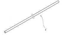
図1には、医療処置具用ワイヤ2が示されている。このワイヤ2は、長尺である。このワイヤ2の太さは、典型的には2.0mm以下であり、特には1.0mm以下である。このワイヤ2の材質は、金属である。 FIG. 1 shows a medical
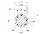
図2には、このワイヤ2の断面が示されている。この断面は、ワイヤ2の長手方向に対して垂直である。図2から明らかなように、この断面の輪郭形状は、円である。輪郭形状が、真円である必要はない。製造上の誤差等の理由により、輪郭形状が真円とは若干異なった形状であっても、本発明では、この輪郭形状は、「円」と称される。 FIG. 2 shows a cross section of the
図2において矢印Dで示されているのは、輪郭形状の円の直径である。換言すれば、このワイヤ2の直径は、Dである。図2において符号4で示された二点鎖線は、仮想円である。この仮想円は、ワイヤ2の輪郭形状である円と同心である。この仮想円4の直径の、直径Dに対する比は、3/4である。従って、ワイヤ2の表面からこの仮想円4までの距離は、図2に示されるように、D/8である。 In FIG. 2, what is indicated by an arrow D is the diameter of the contour circle. In other words, the diameter of the
この仮想円4の上に、第一測定点M1が想定される。この第一測定点M1の位置は、無作為に決定される。次に、この仮想円4の上であって、かつこの仮想円4の中心角において第一測定点M1と45°離間した位置に、第二測定点M2が想定される。以下同様に、45°刻みで、第三測定点M3、第四測定点M4、第五測定点M5、第六測定点M6、第七測定点M7及び第八測定点M8が、想定される。これら8個の測定点は、仮想円4の上において、等ピッチ角で配置されている。 On this virtual circle 4, a first measurement point M1 is assumed. The position of the first measurement point M1 is determined randomly. Next, a second measurement point M2 is assumed on the virtual circle 4 and at a position 45 ° apart from the first measurement point M1 at the central angle of the virtual circle 4. Similarly, the third measurement point M3, the fourth measurement point M4, the fifth measurement point M5, the sixth measurement point M6, the seventh measurement point M7, and the eighth measurement point M8 are assumed in increments of 45 °. These eight measurement points are arranged on the virtual circle 4 at an equal pitch angle.
8個の測定点のそれぞれについて、ビッカース硬度(Hv)が測定される。ビッカース硬度は、「JIS Z 2244:2009」の規格に準じて、マイクロビッカース硬度計により測定される。測定条件は、以下の通りである。
温度:23℃
荷重:100gfVickers hardness (Hv) is measured for each of the eight measurement points. The Vickers hardness is measured by a micro Vickers hardness meter according to the standard of “JIS Z 2244: 2009”. The measurement conditions are as follows.
Temperature: 23 ° C
Load: 100gf
測定点が8個なので、8個の測定値(ビッカース硬度)が得られる。これらの測定値の標準偏差σが、計算される。標準偏差σは、10以下が好ましい。標準偏差σが10以下である医療処置具用ワイヤ2では、周方向における応力集中が生じにくい。このワイヤ2は、耐疲労性に優れる。このワイヤ2が人体に用いられたとき、折損が生じにくい。この観点から、標準偏差σは8以下がより好ましく、5以下が特に好ましい。理想的には、標準偏差σは、ゼロである。 Since there are eight measurement points, eight measurement values (Vickers hardness) are obtained. A standard deviation σ of these measurements is calculated. The standard deviation σ is preferably 10 or less. In the medical
これら8個の測定値(ビッカース硬度)の平均Avは、670以上770以下が好ましい。平均Avが670以上である医療処置具用ワイヤ2は、トルク伝達性に優れる。この観点から、ビッカース硬度の平均Avは690以上がより好ましく、700以上が特に好ましい。この平均Avが770以下であるワイヤ2は、脆くない。従ってこのワイヤ2は、折損しにくい。この観点から、この平均Avは750以下がより好ましく、740以下が特に好ましい。 The average Av of these eight measured values (Vickers hardness) is preferably 670 or more and 770 or less. The medical
ビッカース硬度の、平均Avに対する標準偏差σの比率は、2.0%以下が好ましい。この比率が2.0%以下である医療処置具用ワイヤ2では、周方向における応力集中が生じにくい。このワイヤ2は、耐疲労性に優れる。このワイヤ2が人体に用いられたとき、折損が生じにくい。この観点から、この比率は1.5%以下がより好ましく、0.7%以下が特に好ましい。理想的には、この比率はゼロである。 The ratio of the standard deviation σ to the average Av of the Vickers hardness is preferably 2.0% or less. In the medical
図3は、図1の医療処置具用ワイヤ2が示された正面図である。図3において矢印Lで示されているのは、ワイヤ2の全長である。この全長Lは、前端P1から後端P2までの距離である。図3において、符号P3で示されているのは前端P1からの距離がL*0.1である点であり、符号P4で示されているのは前端P1からの距離がL*0.5である点であり、符号P5で示されているのは前端P1からの距離がL*0.9である点である。 FIG. 3 is a front view showing the medical
点P3においてワイヤ2が切断され、第一断面が得られる。この第一断面は、ワイヤ2の長さ方向に対して垂直である。この第一断面において、前述の第一測定点M1、第二測定点M2、第三測定点M3、第四測定点M4、第五測定点M5、第六測定点M6、第七測定点M7及び第八測定点M8が、想定される。これらの測定点で、ビッカース硬度が測定される。この第一断面において、前述の、標準偏差σの範囲、平均Avの範囲、及び比率(σ/Av)の範囲が達成される。 The
点P4においてワイヤ2が切断され、第二断面が得られる。この第二断面は、ワイヤ2の長さ方向に対して垂直である。この第二断面において、前述の第一測定点M1、第二測定点M2、第三測定点M3、第四測定点M4、第五測定点M5、第六測定点M6、第七測定点M7及び第八測定点M8が、想定される。これらの測定点で、ビッカース硬度が測定される。この第二断面においても、第一断面と同様、前述の、標準偏差σの範囲、平均Avの範囲、及び比率(σ/Av)の範囲が達成される。 The
点P5においてワイヤ2が切断され、第三断面が得られる。この第三断面は、ワイヤ2の長さ方向に対して垂直である。この第三断面において、前述の第一測定点M1、第二測定点M2、第三測定点M3、第四測定点M4、第五測定点M5、第六測定点M6、第七測定点M7及び第八測定点M8が、想定される。これらの測定点で、ビッカース硬度が測定される。この第三断面においても、第一断面と同様、前述の、標準偏差σの範囲、平均Avの範囲、及び比率(σ/Av)の範囲が達成される。 The
図4は、図1のワイヤの製造装置6が示された概念図である。この装置6は、伸線機8、伸線引取機10及び第二矯正器12を有している。伸線機8は、第一コーン14、第二コーン16、複数のダイス18、第一矯正器20及び最終ダイス22を有している。第一コーン14は、直径の異なる複数のローラ24を有している。第二コーン16も、直径の異なる複数のローラ26を有している。ベースワイヤ27は、第一コーン14と第二コーン16との間に張り渡されている。第一コーン14から第二コーン16へ向かう途中で、ベースワイヤ27はダイス18を通過する。ベースワイヤ27は、直径の小さなローラ24、26から直径の大きなローラ24、26へと進行する。この進行により、ベースワイヤ27は長尺化し、かつ細径化する。ベースワイヤ27は、第一矯正器22、最終ダイス22、伸線引取機10及び第二矯正器12を通過する。 FIG. 4 is a conceptual diagram showing the
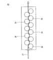
図5は、図4の装置6の第一矯正器20が示された概念図である。図示されていないが、第二矯正器12の構造は、この第一矯正器20の構造と同じである。第一矯正器20は、ジグザグに配置された複数の矯正ローラ28を有する。図5の実施形態では、矯正ローラ28の数は11である。 FIG. 5 is a conceptual diagram showing the
図6は、図5の第一矯正器20の矯正ローラ28が示された拡大正面図である。この矯正ローラは、矯正溝29を有している。この矯正溝29の幅は、ベースワイヤ27の直径とほぼ同じである。図5の実施形態では、矯正ローラ28の数は11である。これらの矯正ローラ28に沿って、ベースワイヤ27がジグザグに進行する。ベースワイヤ27では、矯正溝29によってその表層部全体に繰り返し曲げ加工がなされる。これにより、表層部の硬度の均一性が高められる。 FIG. 6 is an enlarged front view showing the
図4及び5に示された装置6による加工の後、ベースワイヤ27が所定長さに切断され、さらに熱処理が施されて、医療処置具用ワイヤ2が得られる。伸線の条件に工夫が施されることで、標準偏差σが小さなワイヤ2が得られうる。本発明者は、最終伸線の条件を下記の通りとすることで、標準偏差σが小さなワイヤ2が得られることを見いだした。
矯正器の数:2
矯正器の取り付け位置:最終ダイスの前後
矯正ローラーの数:9−13
矯正機出口でのベースワイヤの張力:破断荷重の40%−70%After processing by the
Number of correctors: 2
Corrector mounting position: Before and after the final die Number of correction rollers: 9-13
Base wire tension at outlet of straightener: 40% -70% of breaking load
好ましくは、熱処理は、水素雰囲気でなされる。この雰囲気での熱処理では、熱が短時間でベースワイヤに伝導する。熱処理の温度は、500℃から650℃である。 Preferably, the heat treatment is performed in a hydrogen atmosphere. In the heat treatment in this atmosphere, heat is conducted to the base wire in a short time. The temperature of the heat treatment is 500 ° C. to 650 ° C.
このワイヤ2の好ましい材質は、ステンレス鋼である。ステンレス鋼は、耐食性及び強度に優れる。ステンレス鋼の具体例として、オーステナイト系ステンレス鋼、フェライト系ステンレス鋼、マルテンサイト系ステンレス鋼、析出硬化型ステンレス鋼及び二相ステンレス鋼が挙げられる。オーステナイト系ステンレス鋼が好ましい。このワイヤ2の他の好ましい材質は、Ni−Ti合金及びTi合金である。 A preferred material for the
このワイヤ2の引張強さは、2600MPa以上が好ましい。引張強さが2600MPa以上であるワイヤ2は、このワイヤ2が人体内を進行するときのプッシャビリティに優れる。この観点から、引張強さは2700MPa以上がより好ましく、2800MPa以上が特に好ましい。引張強さは、3000MPa以下が好ましい。 The tensile strength of the
引張強さは、「JIS Z 2241(2011)」の規定に準拠して測定される。測定条件は、以下の通りである。
温度:23℃
引張り速度:10mm/min
評点距離:100mmThe tensile strength is measured in accordance with the provisions of “JIS Z 2241 (2011)”. The measurement conditions are as follows.
Temperature: 23 ° C
Tensile speed: 10 mm / min
Rating distance: 100mm
図7は、図1のワイヤ2の真直度の測定の様子が示された説明図である。この測定では、ワイヤ2の上端近傍が治具30でチャックされる。ワイヤ2のうちチャックされていない部分は、フリー部32と称される。フリー部32に働く力は、重力のみである。図7において、点P6で示されているのはフリー部32の上端であり、点P7で示されているのはフリー部32の下端である。上端P6から下端P7までの距離は、2.00mである。図7における二点鎖線は、鉛直方向に延びている。図7において符号Sで示されているのは、下端P7と二点鎖線との距離(mm)である。この距離Sは、ワイヤ8の下端P7の、鉛直線からのずれである。この距離Sは、真直度である。距離Sが小さいワイヤ8は、真直性に優れている。真直性に劣るワイヤは、このワイヤの湾曲に起因して、距離Sが大きな値となる。 FIG. 7 is an explanatory diagram showing how the straightness of the
このワイヤ2の真直度Sは、0.10mm以下が好ましい。真直度Sが0.10mm以下であるワイヤ2は、トルク伝達性に優れる。この観点から、真直度Sは0.05mm以下がより好ましく、0.02mm以下が特に好ましい。理想的には、真直度Sは、ゼロである。 The straightness S of the
図8は、本発明の一実施形態に係るガイドワイヤ34の一部が示された断面図である。図8において、左端が先端36であり、右端が後端38である。このガイドワイヤ34は、カバー40、芯42、コイル44及び固着材46を備えている。このガイドワイヤ34の全長は、典型的には1500mmから2300mmである。このガイドワイヤ34の線径(太さ)は、典型的には0.30mmから0.60mmである。 FIG. 8 is a cross-sectional view showing a part of the
カバー40は、芯42を覆っている。カバー40は、合成樹脂からなる。典型的な合成樹脂は、テフロン(登録商標)樹脂である。カバー40により、血管へガイドワイヤ34が挿入されるときの円滑性が達成される。 The
芯42は、主部48とテーパー部50とを備えてる。主部48における線径は、実質的に一定である。主部48における線径は、典型的には0.25mmから0.50mmである。テーパー部50は、先端36に向かって縮径している。 The
コイル44は、テーパー部50に巻かれている。コイル44は、テーパー部50の柔軟性を損なうことなく、テーパー部50を補強する。固着材46は、芯42に固定されている。 The
芯42は、図1−3に示された医療処置具用ワイヤ2から形成されている。芯42は、このワイヤ2の先端36の近傍が研削されることで得られる。典型的には、センターレス研削機によって研削がなされる。研削により、テーパー部50が形成される。 The
前述の通り、この芯42は図1−3に示された医療処置具用ワイヤ2から形成されているので、この芯42のビッカース硬度の標準偏差σ、平均Av及び比率(σ/Av)は、医療処置具用ワイヤ2のそれらと同じである。さらに、この芯42の材質、引張り強度及び真直度Sは、医療処置具用ワイヤ2のそれらと同じである。従ってこの芯42は、耐疲労性及びトルク伝達性に優れる。ガイドワイヤ34が、血管が曲がっている部分に挿入された状態で、医師がガイドワイヤ34の前後移動を繰り返しても、芯42の損折が生じにくい。医師がガイドワイヤ34の後端38の近傍を回せば、そのトルクが先端36へと伝達される。従って医師は、ガイドワイヤ34を円滑に操作することができる。 As described above, since the
芯42はテーパー部50を有しているので、図3に示された方法では、ビッカース硬度は測定され得ない。この方法に代わる測定方法が、図9に示されている。この図9において、符号P8で示されているのは主部48とテーパー部50との境界であり、矢印Lで示されているのは主部48の全長である。この全長Lは、境界P8から後端P9までの距離である。図9において、符号P10で示されているのは境界P8からの距離がL*0.1である点であり、符号P11で示されているのは境界P8からの距離がL*0.5である点であり、符号P12で示されているのは境界P8からの距離がL*0.9である点である。 Since the
点P10において芯42が切断され、第一断面が得られる。この第一断面は、芯42の長さ方向に対して垂直である。この第一断面において、前述の第一測定点M1、第二測定点M2、第三測定点M3、第四測定点M4、第五測定点M5、第六測定点M6、第七測定点M7及び第八測定点M8が、想定される。これらの測定点で、ビッカース硬度が測定される。この第一断面において、前述の、標準偏差σの範囲、平均Avの範囲、及び平均Avに対する標準偏差σの比率の範囲が達成される。 The
点P11において芯42が切断され、第二断面が得られる。この第二断面は、芯42の長さ方向に対して垂直である。この第二断面において、前述の第一測定点M1、第二測定点M2、第三測定点M3、第四測定点M4、第五測定点M5、第六測定点M6、第七測定点M7及び第八測定点M8が、想定される。これらの測定点で、ビッカース硬度が測定される。この第二断面においても、第一断面と同様、前述の、標準偏差σの範囲、平均Avの範囲、及び平均Avに対する標準偏差σの比率の範囲が達成される。 The
点P12において芯42が切断され、第三断面が得られる。この第三断面は、芯42の長さ方向に対して垂直である。この第三断面において、前述の第一測定点M1、第二測定点M2、第三測定点M3、第四測定点M4、第五測定点M5、第六測定点M6、第七測定点M7及び第八測定点M8が、想定される。これらの測定点で、ビッカース硬度が測定される。この第三断面においても、第一断面と同様、前述の、標準偏差σの範囲、平均Avの範囲、及び平均Avに対する標準偏差σの比率の範囲が達成される。 The
以下、実施例によって本発明の効果が明らかにされるが、この実施例の記載に基づいて本発明が限定的に解釈されるべきではない。 Hereinafter, the effects of the present invention will be clarified by examples. However, the present invention should not be construed in a limited manner based on the description of the examples.
[実施例1]
材質がSUS304であるベースワイヤに、伸線と熱処理とを繰返し施した。伸線により、ベースワイヤが縮径しつつ長尺化した。最終伸線工程において、仕上がりダイスの前後に設けられた矯正器により、矯正加工を施した。最終伸線工程での線径は、φ0.35mmであった。矯正の条件は、以下の通りである。
矯正ローラーの直径:10mm
矯正ローラーの数:11
矯正器におけるベースワイヤの張力:190N(仕上がりダイス入り口)
170N(仕上がりダイス出口)
最終伸線後のベースワイヤに低温焼鈍を施し、ガイドワイヤ用の芯を得た。低温焼鈍の条件は以下のとおりである。
雰囲気温度:575℃
保持時間:60min
雰囲気ガス:水素[Example 1]
A base wire made of SUS304 was repeatedly subjected to wire drawing and heat treatment. The base wire was elongated while being reduced in diameter by drawing. In the final wire drawing step, straightening was performed with a straightener provided before and after the finished die. The wire diameter in the final wire drawing step was φ0.35 mm. The conditions for correction are as follows.
Straightening roller diameter: 10mm
Number of straightening rollers: 11
Base wire tension in straightener: 190N (finished die entrance)
170N (finished die exit)
The base wire after final drawing was subjected to low-temperature annealing to obtain a guide wire core. The conditions for low temperature annealing are as follows.
Atmospheric temperature: 575 ° C
Holding time: 60 min
Atmospheric gas: Hydrogen
[実施例2]
矯正器における矯正ローラーの数を以下のとおりとした他は実施例1と同様にして、実施例2の芯を得た。
矯正ローラーの数:9[Example 2]
A core of Example 2 was obtained in the same manner as Example 1 except that the number of correction rollers in the corrector was as follows.
Number of straightening rollers: 9
[実施例3]
矯正器におけるベースワイヤの張力を以下のとおりとした他は実施例1と同様にして、実施例3の芯を得た。
矯正器におけるベースワイヤの張力:175N(仕上がりダイス入り口)
155N(仕上がりダイス出口)[Example 3]
A core of Example 3 was obtained in the same manner as Example 1 except that the tension of the base wire in the straightener was as follows.
Base wire tension in straightener: 175N (finished die entrance)
155N (finished die exit)
[実施例4]
矯正器における矯正ローラーの数を以下のとおりとした他は実施例3と同様にして、実施例4の芯を得た。
矯正ローラーの数:9[Example 4]
A core of Example 4 was obtained in the same manner as Example 3 except that the number of correction rollers in the corrector was as follows.
Number of straightening rollers: 9
[比較例1]
最終伸線工程で矯正器を使用しなかった他は実施例1と同様にして、比較例1の芯を得た。[Comparative Example 1]
A core of Comparative Example 1 was obtained in the same manner as in Example 1 except that the straightener was not used in the final wire drawing step.
[比較例2]
矯正器における矯正ローラーの数及びベースワイヤの張力を以下のとおりとした他は実施例1と同様にして、比較例2の芯を得た。
矯正ローラーの数:18
矯正器におけるベースワイヤの張力:190N(仕上がりダイス入り口)
190N(仕上がりダイス出口)[Comparative Example 2]
A core of Comparative Example 2 was obtained in the same manner as in Example 1 except that the number of correcting rollers and the tension of the base wire in the corrector were as follows.
Number of straightening rollers: 18
Base wire tension in straightener: 190N (finished die entrance)
190N (finished die exit)
[評価]
前述の方法にて、断面硬度の平均値及び標準偏差を測定した。前述の方法にて芯の引張強さ及び真直度を測定した。さらに、芯の疲労値を測定した。この疲労値の測定は、BEKAERT社製のハンター疲労試験機を使用した。湿度が40%である大気中で試験応力を1000−1500MPaとし、5本の試験サンプルが全て107の疲労限に達した応力を疲労値とした。この結果が、下記の表1に示されている。[Evaluation]
The average value and standard deviation of the cross-sectional hardness were measured by the method described above. The tensile strength and straightness of the core were measured by the method described above. Furthermore, the fatigue value of the core was measured. The fatigue value was measured using a Hunter fatigue tester manufactured by BEKAERT. The test stress was set to 1000 to 1500 MPa in the atmosphere where the humidity was 40%, and the stress at which all five test samples reached the fatigue limit of 107 was set as the fatigue value. The results are shown in Table 1 below.

表1の評価結果から、本発明の優位性は明かである。 From the evaluation results in Table 1, the superiority of the present invention is clear.
本発明に係るワイヤは、様々な医療処置具に適用されうる。 The wire according to the present invention can be applied to various medical treatment instruments.
2・・・医療処置具用ワイヤ
4・・・仮想円
6・・・製造装置
8・・・伸線機
10・・・伸線引取機
12・・・第二矯正器
14・・・第一コーン
16・・・第二コーン
18・・・ダイス
20・・・第一矯正器
22・・・最終ダイス
24、26・・・ローラ
27・・・ベースワイヤ
28・・・矯正ローラ
29・・・矯正溝
30・・・治具
32・・・フリー部
34・・・ガイドワイヤ
40・・・カバー
42・・・芯
44・・・コイル
48・・・主部
50・・・テーパー部DESCRIPTION OF
Claims (7)
Translated fromJapanese上記断面において、上記円と同心でありその直径が(3/4)Dである仮想円上に等間隔に位置する8個の測定点の、ビッカース硬度の標準偏差σが、10以下であり、
上記8個の測定点におけるビッカース硬度の平均が、670以上770以下である医療処置具用ワイヤ。The contour shape of the cross section perpendicular to the longitudinal direction is a circle whose diameter is D,
In the cross section, of a said circle concentric its diameter (3/4) D 8 measuring points located at equal intervals on an imaginary circle is, the standard deviation σ of the Vickers hardnessstate, and are 10 or less,
The average Vickers hardness at eight measuring points above, 670 or more 770 der Ru medical treatment instrument wirebelow.
上記芯の、長手方向に対して垂直な断面の輪郭形状が、その直径がDである円であり、
上記断面において、上記円と同心でありその直径が(3/4)Dである仮想円上に等間隔に位置する8個の測定点の、ビッカース硬度の標準偏差σが、10以下であり、
上記8個の測定点におけるビッカース硬度の平均が、670以上770以下であるガイドワイヤ。Has a wick,
The outline shape of the cross section of the core perpendicular to the longitudinal direction is a circle whose diameter is D,
In the cross section, of a said circle concentric its diameter (3/4) D 8 measuring points located at equal intervals on an imaginary circle is, the standard deviation σ of the Vickers hardnessstate, and are 10 or less,
The average Vickers hardness at eight measuring points above, 670 or more 770 der Ru guidewirebelow.
The guide wire according toclaim 5 or 6 , wherein the core has a tensile strength of 2600 MPa or more.
Priority Applications (4)
| Application Number | Priority Date | Filing Date | Title |
|---|---|---|---|
| JP2017140985AJP6596470B2 (en) | 2017-07-20 | 2017-07-20 | Medical treatment device wire and guide wire |
| US16/630,882US20200147353A1 (en) | 2017-07-20 | 2018-06-26 | Wire for medical treatment instrument and guide wire |
| PCT/JP2018/024237WO2019017164A1 (en) | 2017-07-20 | 2018-06-26 | Medical treatment wire and guide wire |
| CN201880046632.8ACN110891642B (en) | 2017-07-20 | 2018-06-26 | Wire for medical treatment instrument and guide wire |
Applications Claiming Priority (1)
| Application Number | Priority Date | Filing Date | Title |
|---|---|---|---|
| JP2017140985AJP6596470B2 (en) | 2017-07-20 | 2017-07-20 | Medical treatment device wire and guide wire |
Publications (2)
| Publication Number | Publication Date |
|---|---|
| JP2019017856A JP2019017856A (en) | 2019-02-07 |
| JP6596470B2true JP6596470B2 (en) | 2019-10-23 |
Family
ID=65016271
Family Applications (1)
| Application Number | Title | Priority Date | Filing Date |
|---|---|---|---|
| JP2017140985AActiveJP6596470B2 (en) | 2017-07-20 | 2017-07-20 | Medical treatment device wire and guide wire |
Country Status (4)
| Country | Link |
|---|---|
| US (1) | US20200147353A1 (en) |
| JP (1) | JP6596470B2 (en) |
| CN (1) | CN110891642B (en) |
| WO (1) | WO2019017164A1 (en) |
Cited By (1)
| Publication number | Priority date | Publication date | Assignee | Title |
|---|---|---|---|---|
| WO2024075413A1 (en) | 2022-10-05 | 2024-04-11 | 朝日インテック株式会社 | Medical wire material and guide wire |
Families Citing this family (3)
| Publication number | Priority date | Publication date | Assignee | Title |
|---|---|---|---|---|
| EP4341453A1 (en)* | 2021-05-21 | 2024-03-27 | NV Bekaert SA | A straight stainless steel wire for flexible card clothing |
| JP7458469B1 (en)* | 2022-12-22 | 2024-03-29 | トクセン工業株式会社 | Straight wire for medical treatment instruments |
| IT202300001206A1 (en)* | 2023-01-27 | 2024-07-27 | Eurolls S P A | PRODUCTION LINE AND PROCEDURE FOR AUTOMATICALLY PRODUCING THREADED METAL PRODUCTS |
Family Cites Families (14)
| Publication number | Priority date | Publication date | Assignee | Title |
|---|---|---|---|---|
| JP4339941B2 (en)* | 1998-07-03 | 2009-10-07 | 清仁 石田 | Guide wire core material, guide wire, and manufacturing method thereof |
| JP2004181184A (en)* | 2002-12-03 | 2004-07-02 | Teruo Hashimoto | Medical guide wire |
| JP4607440B2 (en)* | 2003-09-26 | 2011-01-05 | 株式会社東芝 | Titanium alloy wire or rod, titanium alloy member, and method for manufacturing titanium alloy wire or rod |
| JP2008184643A (en)* | 2007-01-29 | 2008-08-14 | Nippon Seisen Co Ltd | Method for manufacturing high-strength ultra-fine flat wire, and high-strength metal ultra-fine flat wire obtained using the manufacturing method |
| JP5149537B2 (en)* | 2007-05-15 | 2013-02-20 | 日立電線株式会社 | Wire straightening device and solar cell assembly device |
| JP5386088B2 (en)* | 2008-01-25 | 2014-01-15 | 金井 宏彰 | Guide wire core, method for manufacturing the core, and medical guide wire using the core |
| JP5089803B2 (en)* | 2009-03-04 | 2012-12-05 | 株式会社パイオラックスメディカルデバイス | Core wire for guide wire and manufacturing method thereof |
| JP5436304B2 (en)* | 2010-03-30 | 2014-03-05 | 朝日インテック株式会社 | Medical guide wire, and assembly of medical guide wire and microcatheter, or balloon catheter and guiding catheter |
| US9629873B2 (en)* | 2010-07-02 | 2017-04-25 | University Of Florida Research Foundation, Inc. | Bioresorbable metal alloy and implants made of same |
| JP6073016B2 (en)* | 2011-11-04 | 2017-02-01 | ニプロ株式会社 | Manufacturing method of injection needle |
| US9339398B2 (en)* | 2012-04-26 | 2016-05-17 | Medtronic Vascular, Inc. | Radiopaque enhanced nickel alloy for stents |
| JP5882827B2 (en)* | 2012-04-27 | 2016-03-09 | 株式会社ブリヂストン | Steel wire, method for manufacturing steel wire, and method for evaluating steel wire |
| US9636485B2 (en)* | 2013-01-17 | 2017-05-02 | Abbott Cardiovascular Systems, Inc. | Methods for counteracting rebounding effects during solid state resistance welding of dissimilar materials |
| CN105980589B (en)* | 2014-03-06 | 2018-01-16 | 新日铁住金株式会社 | The carbon steel wire rod with high and its manufacture method of excellent in wire-drawing workability |
- 2017
- 2017-07-20JPJP2017140985Apatent/JP6596470B2/enactiveActive
- 2018
- 2018-06-26CNCN201880046632.8Apatent/CN110891642B/enactiveActive
- 2018-06-26USUS16/630,882patent/US20200147353A1/ennot_activeAbandoned
- 2018-06-26WOPCT/JP2018/024237patent/WO2019017164A1/ennot_activeCeased
Cited By (1)
| Publication number | Priority date | Publication date | Assignee | Title |
|---|---|---|---|---|
| WO2024075413A1 (en) | 2022-10-05 | 2024-04-11 | 朝日インテック株式会社 | Medical wire material and guide wire |
Also Published As
| Publication number | Publication date |
|---|---|
| CN110891642B (en) | 2022-11-18 |
| JP2019017856A (en) | 2019-02-07 |
| WO2019017164A1 (en) | 2019-01-24 |
| CN110891642A (en) | 2020-03-17 |
| US20200147353A1 (en) | 2020-05-14 |
Similar Documents
| Publication | Publication Date | Title |
|---|---|---|
| JP6596470B2 (en) | Medical treatment device wire and guide wire | |
| US7909779B2 (en) | Catheter and method of producing the same | |
| JP4719320B2 (en) | High strength extra fine steel wire and method for producing the same | |
| EP3293306A1 (en) | Hollow twisted wire for operation | |
| US7699792B2 (en) | Catheter guide wire especially for percutaneous transluminal coronary angioplasty | |
| CN101238968A (en) | Wire-stranded hollow coil body, a medical equipment made from the same and making method | |
| JP2011167387A (en) | Guidewire | |
| US11684759B2 (en) | Guidewire having varying diameters and method of making | |
| US20120245488A1 (en) | Guidewire | |
| JP5219545B2 (en) | Guide wire core and method for evaluating the core | |
| TW201325642A (en) | Medical guide wire | |
| JP5386088B2 (en) | Guide wire core, method for manufacturing the core, and medical guide wire using the core | |
| JP4851878B2 (en) | Tubular knitted body for catheter reinforcement and catheter using the same | |
| CN113811958B (en) | Copper-clad steel wire, twisted wire, insulated wire and cable | |
| EP2865407A1 (en) | Coil body and guide wire | |
| EP4427789A1 (en) | Guide wire | |
| JP2019044305A (en) | Medical equipment operating rope | |
| JP5896480B2 (en) | Guide wire | |
| WO2014103476A1 (en) | Medical guide wire | |
| EP4223351A1 (en) | Guide wire and method of manufacturing guide wire | |
| CN106922137B (en) | Shaped wire with controlled curvature at the bend | |
| JP7458469B1 (en) | Straight wire for medical treatment instruments | |
| JP5622201B2 (en) | Guide wire and catheter | |
| JP2023007516A (en) | guide wire | |
| US20250229009A1 (en) | Medical wire material and guide wire |
Legal Events
| Date | Code | Title | Description |
|---|---|---|---|
| A621 | Written request for application examination | Free format text:JAPANESE INTERMEDIATE CODE: A621 Effective date:20180514 | |
| RD02 | Notification of acceptance of power of attorney | Free format text:JAPANESE INTERMEDIATE CODE: A7422 Effective date:20180514 | |
| A131 | Notification of reasons for refusal | Free format text:JAPANESE INTERMEDIATE CODE: A131 Effective date:20190319 | |
| A521 | Request for written amendment filed | Free format text:JAPANESE INTERMEDIATE CODE: A523 Effective date:20190412 | |
| TRDD | Decision of grant or rejection written | ||
| A01 | Written decision to grant a patent or to grant a registration (utility model) | Free format text:JAPANESE INTERMEDIATE CODE: A01 Effective date:20190924 | |
| A61 | First payment of annual fees (during grant procedure) | Free format text:JAPANESE INTERMEDIATE CODE: A61 Effective date:20190930 | |
| R150 | Certificate of patent or registration of utility model | Ref document number:6596470 Country of ref document:JP Free format text:JAPANESE INTERMEDIATE CODE: R150 | |
| R250 | Receipt of annual fees | Free format text:JAPANESE INTERMEDIATE CODE: R250 | |
| R250 | Receipt of annual fees | Free format text:JAPANESE INTERMEDIATE CODE: R250 | |
| R250 | Receipt of annual fees | Free format text:JAPANESE INTERMEDIATE CODE: R250 | |
| R250 | Receipt of annual fees | Free format text:JAPANESE INTERMEDIATE CODE: R250 |