JP6595824B2 - Utilizing resin runner burr in fuel cell separator manufacturing - Google Patents
Utilizing resin runner burr in fuel cell separator manufacturingDownload PDFInfo
- Publication number
- JP6595824B2 JP6595824B2JP2015138711AJP2015138711AJP6595824B2JP 6595824 B2JP6595824 B2JP 6595824B2JP 2015138711 AJP2015138711 AJP 2015138711AJP 2015138711 AJP2015138711 AJP 2015138711AJP 6595824 B2JP6595824 B2JP 6595824B2
- Authority
- JP
- Japan
- Prior art keywords
- resin
- burr
- molded product
- runner burr
- frame
- Prior art date
- Legal status (The legal status is an assumption and is not a legal conclusion. Google has not performed a legal analysis and makes no representation as to the accuracy of the status listed.)
- Active
Links
- 239000011347resinSubstances0.000titleclaimsdescription113
- 229920005989resinPolymers0.000titleclaimsdescription113
- 238000004519manufacturing processMethods0.000titleclaimsdescription20
- 239000000446fuelSubstances0.000titleclaimsdescription15
- 238000000034methodMethods0.000claimsdescription17
- 230000002093peripheral effectEffects0.000claimsdescription16
- 238000000465mouldingMethods0.000claimsdescription7
- 125000006850spacer groupChemical group0.000description3
- 238000013404process transferMethods0.000description2
- 238000007689inspectionMethods0.000description1
- 238000012546transferMethods0.000description1
Images


Classifications
- Y—GENERAL TAGGING OF NEW TECHNOLOGICAL DEVELOPMENTS; GENERAL TAGGING OF CROSS-SECTIONAL TECHNOLOGIES SPANNING OVER SEVERAL SECTIONS OF THE IPC; TECHNICAL SUBJECTS COVERED BY FORMER USPC CROSS-REFERENCE ART COLLECTIONS [XRACs] AND DIGESTS
- Y02—TECHNOLOGIES OR APPLICATIONS FOR MITIGATION OR ADAPTATION AGAINST CLIMATE CHANGE
- Y02E—REDUCTION OF GREENHOUSE GAS [GHG] EMISSIONS, RELATED TO ENERGY GENERATION, TRANSMISSION OR DISTRIBUTION
- Y02E60/00—Enabling technologies; Technologies with a potential or indirect contribution to GHG emissions mitigation
- Y02E60/30—Hydrogen technology
- Y02E60/50—Fuel cells
- Y—GENERAL TAGGING OF NEW TECHNOLOGICAL DEVELOPMENTS; GENERAL TAGGING OF CROSS-SECTIONAL TECHNOLOGIES SPANNING OVER SEVERAL SECTIONS OF THE IPC; TECHNICAL SUBJECTS COVERED BY FORMER USPC CROSS-REFERENCE ART COLLECTIONS [XRACs] AND DIGESTS
- Y02—TECHNOLOGIES OR APPLICATIONS FOR MITIGATION OR ADAPTATION AGAINST CLIMATE CHANGE
- Y02P—CLIMATE CHANGE MITIGATION TECHNOLOGIES IN THE PRODUCTION OR PROCESSING OF GOODS
- Y02P70/00—Climate change mitigation technologies in the production process for final industrial or consumer products
- Y02P70/50—Manufacturing or production processes characterised by the final manufactured product
Landscapes
- Fuel Cell (AREA)
Description
Translated fromJapanese本発明は、燃料電池用セパレータに係り、更に詳しくは、燃料電池用セパレータを製造する際にその外周側に一体に成形する樹脂ランナーバリの活用方法に関する。 The present invention relates to a fuel cell separator, and more particularly to a method for utilizing a resin runner burr that is integrally formed on the outer peripheral side of a fuel cell separator.
従来から図5に示すように、セパレータプレート52の外周部に樹脂フレーム53を一体成形するとともに樹脂フレーム53の平面上または内周側(図では内周側)にゴムガスケット54を一体成形してなる燃料電池用セパレータ51が知られている。 Conventionally, as shown in FIG. 5, a
しかしながら、セパレータプレート52はその板厚が薄く、樹脂フレーム53はその線径が細い(断面積が小さい)ため、当該セパレータ51を製造する過程でセパレータプレート52が変形したり樹脂フレーム53が破損したりしないよう取り扱い方に注意を必要とする。したがって製造過程の進行に長時間を必要とし、製造過程を速やかに行うことが困難であると云う不都合がある。 However, since the
本発明は以上の点に鑑みて、セパレータプレートの外周部に樹脂フレームを一体成形してなる燃料電池用セパレータを製造する際に、その製造過程を速やかに行うことができる方法を提供することを目的とする。 In view of the above, the present invention provides a method capable of quickly performing the manufacturing process when manufacturing a separator for a fuel cell formed by integrally molding a resin frame on the outer periphery of a separator plate. Objective.
上記目的を達成するため、本発明の燃料電池セパレータ製造における樹脂ランナーバリの活用方法は、金型を用いてセパレータプレートの外周部に樹脂フレームを一体成形する際に前記樹脂フレームのさらに外周側に樹脂ランナーバリを一体に成形し、前記樹脂フレームから前記樹脂ランナーバリを切り離すことなく前記セパレータプレート、樹脂フレームおよび樹脂ランナーバリを含む成形品を一体のままで離型し、離型後、前記樹脂ランナーバリを成形品搬送用の枠体として利用しながら前記成形品の搬送を行うことを特徴とする。 In order to achieve the above object, the method of utilizing the resin runner burr in the manufacture of the fuel cell separator of the present invention is to further increase the outer peripheral side of the resin frame when the resin frame is integrally formed on the outer peripheral portion of the separator plate using a mold. A resin runner burr is integrally molded, and the molded product including the separator plate, the resin frame, and the resin runner burr is released as a single piece without separating the resin runner burr from the resin frame. The molded product is conveyed while using a runner burr as a frame for conveying the molded product.
本発明では、金型を用いてセパレータプレートの外周部に樹脂フレームを一体成形する際に樹脂フレームのさらに外周側に樹脂ランナーバリを一体に成形し、この樹脂ランナーバリを切り離すことなく一体のまま離型して、成形品搬送用の枠体として利用する。したがって樹脂ランナーバリによって成形品の製品部が補強された状態で搬送が行なわれるため、セパレータプレートが変形したり樹脂フレームが破損したりしにくくなり、よって製造過程をスピードアップすることが可能とされる。 In the present invention, when the resin frame is integrally formed on the outer peripheral portion of the separator plate using the mold, the resin runner burr is integrally formed on the outer peripheral side of the resin frame, and the resin runner burr remains integrated without being separated. The mold is released and used as a frame for conveying a molded product. Therefore, since the transfer is performed in a state where the product portion of the molded product is reinforced by the resin runner burr, it is difficult for the separator plate to be deformed or the resin frame to be damaged, and thus the manufacturing process can be speeded up. The
また、樹脂ランナーバリは、金型による樹脂フレームの成形に際し必須で成形される(必ず必要とされる)ものであって、成形品を搬送するために特別に成形されるものではない。したがってこのような樹脂ランナーバリを有効に活用することにより製造過程のスピードアップを図ることは、きわめて合理的であると云うことができる。 The resin runner burr is formed indispensable (necessarily required) when the resin frame is molded by the mold, and is not specially formed for conveying the molded product. Therefore, it can be said that it is extremely reasonable to speed up the manufacturing process by effectively utilizing such a resin runner burr.
樹脂ランナーバリの平面形状としては、当該バリの強度を確保するため、樹脂フレームのさらに外周側を全周に亙って巡る形状とするのが好ましい。 As a planar shape of the resin runner burr, it is preferable that the resin frame further has a shape that surrounds the entire outer periphery of the resin frame in order to ensure the strength of the burr.
樹脂ランナーバリは例えば、成形品の自動搬送における被チャック体(成形品チャック装置によってチャックされる対象物)として利用されるが、そのほか、複数の成形品を積み重ねた状態とするときに成形品の製品部同士が直接接触しないようにする一種のスペーサーとして利用することも考えられる。そしてこの場合には、樹脂ランナーバリの厚み寸法を樹脂フレームの厚み寸法よりも大きく設定するとともに樹脂ランナーバリの厚み寸法の領域内に樹脂フレームを配置することにし、これにより複数の成形品を積み重ねたときに樹脂ランナーバリ同士を積み重ね、セパレータプレートおよび樹脂フレームよりなる成形品の製品部同士間には積み重ね方向に間隙を設定する。したがって成形品の製品部同士が直接接触するのを防止することが可能とされる。 For example, the resin runner burr is used as a chucked body (object to be chucked by the molded product chuck device) in the automatic conveyance of the molded product, but in addition, when a plurality of molded products are stacked, It may be used as a kind of spacer that prevents product parts from directly contacting each other. In this case, the thickness dimension of the resin runner burr is set larger than the thickness dimension of the resin frame, and the resin frame is arranged in the area of the thickness dimension of the resin runner burr, thereby stacking a plurality of molded products. When the resin runner burrs are stacked, a gap is set in the stacking direction between the product parts of the molded product made of the separator plate and the resin frame. Therefore, it is possible to prevent the product parts of the molded product from directly contacting each other.
また、成形品の製品部が、セパレータプレートの外周部に樹脂フレームを一体成形するとともに樹脂フレームの平面上または内周側にゴムガスケットを一体成形したものであるときには加えて、ゴムガスケットの厚み寸法を樹脂ランナーバリの厚み寸法よりも小さく設定するとともに樹脂ランナーバリの厚み寸法の領域内にゴムガスケットを配置することにし、これにより複数の成形品を積み重ねたときに樹脂ランナーバリ同士を積み重ね、セパレータプレート、樹脂フレームおよびゴムガスケットよりなる成形品の製品部同士間には積み重ね方向に間隙を設定する。したがってやはり、成形品の製品部同士が直接接触するのを防止することが可能とされる。 In addition, when the product part of the molded product is formed by integrally molding the resin frame on the outer peripheral part of the separator plate and integrally molding the rubber gasket on the flat surface or the inner peripheral side of the resin frame, the thickness dimension of the rubber gasket is added. Is set to be smaller than the thickness dimension of the resin runner burr, and a rubber gasket is arranged in the area of the thickness dimension of the resin runner burr, thereby stacking the resin runner burr together when a plurality of molded products are stacked. A gap is set in the stacking direction between the product parts of the molded product including the plate, the resin frame, and the rubber gasket. Therefore, it is possible to prevent the product parts of the molded product from directly contacting each other.
本発明によれば、セパレータプレートの外周部に樹脂フレームを一体成形してなる燃料電池用セパレータを製造するに際し樹脂ランナーバリを有効に活用するため、燃料電池用セパレータの製造過程を速やかに行うことができる。 According to the present invention, in order to effectively utilize the resin runner burr when manufacturing a fuel cell separator formed by integrally molding a resin frame on the outer peripheral portion of the separator plate, the manufacturing process of the fuel cell separator is performed quickly. Can do.
本発明には、以下の実施形態が含まれる。
(1)本発明は、燃料電池用セパレータ樹脂ランナー活用に関する。
(2)本発明は、樹脂成形時のランナーをハンドリング(成形品取り扱い)に活用するものである。
(3)セパレータの外周部へ樹脂フレームを成形する際にランナーが樹脂フレームの外周に形成され、各工程での製品搬送用の枠体としてランナーを活用する。ランナーは強度が充分あるため、製品搬送を自動化するときも有効に活用できる。
(4)樹脂フレームの外周に形成されるランナーを活用して工程内搬送を行う。ランナーが工程間搬送治具を兼ねることができ、別途、工程間搬送治具の準備が必要なくなる。また、各工程において製品ハンドリングはランナーをもって取り扱うことができるので、取り扱いが容易になる。自動化の際の製品チャックはランナーをつかむ。
(5)本発明によれば、作業効率を向上させることができ、作業効率の向上による生産コストの低減を図ることができる。The present invention includes the following embodiments.
(1) The present invention relates to utilization of a separator resin runner for a fuel cell.
(2) The present invention utilizes a runner at the time of resin molding for handling (molded product handling).
(3) When the resin frame is formed on the outer peripheral portion of the separator, a runner is formed on the outer periphery of the resin frame, and the runner is used as a frame for product conveyance in each process. Runners are strong enough to be used effectively when automating product transport.
(4) In-process conveyance is performed using a runner formed on the outer periphery of the resin frame. The runner can also serve as an inter-process transfer jig, and it is not necessary to prepare an inter-process transfer jig. Moreover, since product handling can be handled with a runner in each process, handling becomes easy. The product chuck during automation grabs the runner.
(5) According to the present invention, the work efficiency can be improved, and the production cost can be reduced by improving the work efficiency.
つぎに本発明の実施例を図面にしたがって説明する。 Next, embodiments of the present invention will be described with reference to the drawings.
図1は、当該実施例にて取り扱うバリ付き成形品11の全体平面を示している。 FIG. 1 shows the entire plane of a molded
このバリ付き成形品11は図2(A)に示すように、平面長方形状を呈するセパレータプレート12の四辺外周部に樹脂フレーム13を一体成形した燃料電池用セパレータを製造するに際しての中間成形品であって、この中間成形品に対し図2(B)に示すようにセパレータプレート12の厚み方向両面側であって樹脂フレーム13の平面上および内周側にゴムガスケット14を一体成形し、さらに図2(C)に示すようにバリ21を切り離すことにより、燃料電池用セパレータ製品としての完成に至る。樹脂フレーム13はセパレータプレート12の四辺外周部に全周に亙って設けられ、ゴムガスケット14も全周に亙って設けられている。 As shown in FIG. 2A, the burr-formed molded
バリ21は、セパレータプレート12の外周部に樹脂フレーム13を一体成形するときに生じるものであって、樹脂フレーム13のさらに外周側に全周に亙って成形される樹脂ランナーバリ22と、樹脂フレーム13および樹脂ランナーバリ22間に両者13,22を連続するように成形される周上複数(図1では10箇所)の樹脂ゲートバリ23との組み合わせよりなる。以下では、樹脂ランナーバリ22に対し樹脂ゲートバリ23を一体のものとして説明する。 The
また、当該実施例では特に、以下の手順にて燃料電池用セパレータを製造する。 In this embodiment, in particular, a fuel cell separator is manufactured by the following procedure.
図1および図2(A)に示すように、先ずセパレータプレート12を用意し、次いで金型(図示せず)を用いてこのセパレータプレート12の外周部に全周に亙って樹脂フレーム13を一体成形し、このとき樹脂フレーム13のさらに外周側に全周に亙って樹脂ランナーバリ22を一体に成形する。 As shown in FIG. 1 and FIG. 2A, first, a
次いで、樹脂フレーム13から樹脂ランナーバリ22を切り離すことなくセパレータプレート12、樹脂フレーム13および樹脂ランナーバリ22を含むバリ付き成形品11を一体のままで離型する。 Next, the
次いで、樹脂ランナーバリ22を成形品搬送用の枠体として利用しながらバリ付き成形品11の搬送を行い、具体的には例えば、樹脂ランナーバリ22を成形品自動搬送における被チャック体(成形品チャック装置によってチャックされる対象物)として利用しながらバリ付き成形品11の搬送を行う。 Next, the
次いで、図2(B)に示すように、別途の金型(図示せず)を用いてバリ付き成形品11に対しゴムガスケット14を一体成形する。 Next, as shown in FIG. 2B, a
次いで、樹脂フレーム13から樹脂ランナーバリ22を切り離すことなくセパレータプレート12、樹脂フレーム13、樹脂ランナーバリ22およびゴムガスケット14を含むバリ付き成形品11を一体のままで離型する。 Next, the molded
次いで、樹脂ランナーバリ22を成形品搬送用の枠体として利用しながらバリ付き成形品11の搬送を行い、具体的には例えば、樹脂ランナーバリ22を成形品自動搬送における被チャック体(成形品チャック装置によってチャックされる対象物)として利用しながらバリ付き成形品11の搬送を行う。 Next, the molded
次いで、図2(C)に示すように、樹脂フレーム13から樹脂ランナーバリ22を切り離し、所要の検査工程などを経て、完成に至る。 Next, as shown in FIG. 2C, the resin runner burrs 22 are separated from the
したがって上記の方法によれば、樹脂ランナーバリ22を成形品搬送用の枠体として有効に活用しながら成形品の搬送を行うため、製造過程における作業効率を向上させることができ、製造過程を速やかに行うことができる。また樹脂ランナーバリ22は、金型による樹脂フレーム13の成形に際し必須で成形されるにものであって、成形品の搬送するために特別に成形されるものではない。したがってこのような樹脂ランナーバリ22を有効に活用して製造過程における作業効率を向上させ製造過程を速やかに行うことは、きわめて合理的である。 Therefore, according to the above method, since the molded product is conveyed while effectively using the
また、上記の構成において図2(A)に示したように、樹脂ランナーバリ22はその厚み寸法w1が樹脂フレーム13の厚み寸法w2よりも大きく設定され(w1>w2)、樹脂ランナーバリ22の厚み寸法w1の領域内に樹脂フレーム13が配置されるように構成されている。Further, as illustrated in FIG. 2 (A) In the above configuration, the
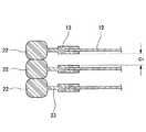
したがって、樹脂ランナーバリ22はこれを、複数の成形品を積み重ねた状態で保管するときに成形品の製品部同士が直接接触しないようにする一種のスペーサーとして利用することが可能とされており、すなわち図3に示すように、複数の成形品を積み重ねたときに樹脂ランナーバリ22同士が積み重ね体として積み重ねられ、セパレータプレート12および樹脂フレーム13よりなる成形品の製品部同士間には積み重ね方向に間隙c1が設定される。したがって成形品の製品部同士が直接接触するのを防止することが可能とされている。Therefore, the
また、図2(B)に示したように、ゴムガスケット14はその厚み寸法w3が樹脂ランナーバリ22の厚み寸法w1よりも小さく設定され(w3<w1)、樹脂ランナーバリ22の厚み寸法w1の領域内にゴムガスケット14が配置されている。Also, as shown in FIG. 2B, the
したがって同様に、樹脂ランナーバリ22はこれを、複数の成形品を積み重ねた状態で保管するときに成形品の製品部同士が直接接触しないようにする一種のスペーサーとして利用することが可能とされており、すなわち図4に示すように、複数の成形品を積み重ねたときに樹脂ランナーバリ22同士が積み重ね体として積み重ねられ、セパレータプレート12、樹脂フレーム13およびゴムガスケット14よりなる成形品の製品部同士間には積み重ね方向に間隙c2が設定される。したがって、このようにゴムガスケット14を一体成形したのちにおいても成形品の製品部同士が直接接触するのを防止し、製品部同士が粘着してしまうこと等を防止することが可能とされている。Therefore, similarly, the
また、樹脂ランナーバリ22が全周に亙ってエンドレスに成形されているため、この樹脂ランナーバリ22は強度が大きいものである。したがってこのような樹脂ランナーバリ22を枠体として成形品を取り扱うことになるため、行程中セパレータプレート12が変形したり樹脂フレーム13が破損したりするのを有効に防止することができる。 Further, since the
11 バリ付き成形品
12 セパレータプレート
13 樹脂フレーム
14 ゴムガスケット
21 バリ
22 樹脂ランナーバリ
23 樹脂ゲートバリ11 Molded product with
Claims (3)
Translated fromJapanese前記樹脂フレームから前記樹脂ランナーバリを切り離すことなく前記セパレータプレート、樹脂フレームおよび樹脂ランナーバリを含む成形品を一体のままで離型し、
離型後、前記樹脂ランナーバリを成形品搬送用の枠体として利用しながら前記成形品の搬送を行うことを特徴とする燃料電池セパレータ製造における樹脂ランナーバリ活用方法。When integrally molding the resin frame on the outer periphery of the separator plate using a mold, the resin runner burr is integrally molded over theentire outer periphery of the resin frame,
Without separating the resin runner burr from the resin frame, the molded product including the separator plate, the resin frame and the resin runner burr is released as a single unit,
A method for utilizing a resin runner burr in manufacturing a fuel cell separator, wherein the molded product is conveyed while being used as a frame for conveying a molded product after release.
前記樹脂ランナーバリの厚み寸法を前記樹脂フレームの厚み寸法よりも大きく設定するとともに前記樹脂ランナーバリの厚み寸法の領域内に前記樹脂フレームを配置することにより、前記樹脂ランナーバリを成形品積み重ね時の積み重ね体として利用しながら前記成形品の積み重ねを行うことを特徴とする燃料電池セパレータ製造における樹脂ランナーバリ活用方法。The method ofclaim 1 , wherein
By setting the thickness dimension of the resin runner burr larger than the thickness dimension of the resin frame and disposing the resin frame in the area of the thickness dimension of the resin runner burr, A method for utilizing a resin runner burr in manufacturing a fuel cell separator, wherein the molded product is stacked while being used as a stack.
前記離型後に前記成形品における前記樹脂フレームの平面上または内周側にゴムガスケットを一体成形する工程をさらに実施し、このとき前記ゴムガスケットの厚み寸法を前記樹脂ランナーバリの厚み寸法よりも小さく設定するとともに前記樹脂ランナーバリの厚み寸法の領域内に前記ゴムガスケットを配置することにより、前記樹脂ランナーバリを成形品積み重ね時の積み重ね体として利用しながら前記ゴムガスケットを含む前記成形品の積み重ねを行うことを特徴とする燃料電池セパレータ製造における樹脂ランナーバリ活用方法。
The method ofclaim 2 , wherein
After the mold release, a step of integrally molding a rubber gasket on a flat surface or an inner peripheral side of the resin frame in the molded product is performed, and at this time, the thickness dimension of the rubber gasket is smaller than the thickness dimension of the resin runner burr Setting and placing the rubber gasket in the region of the thickness dimension of the resin runner burr enables stacking of the molded product including the rubber gasket while using the resin runner burr as a stacked body when stacking molded products. A method for utilizing a resin runner burr in the manufacture of a fuel cell separator.
Priority Applications (1)
| Application Number | Priority Date | Filing Date | Title |
|---|---|---|---|
| JP2015138711AJP6595824B2 (en) | 2015-07-10 | 2015-07-10 | Utilizing resin runner burr in fuel cell separator manufacturing |
Applications Claiming Priority (1)
| Application Number | Priority Date | Filing Date | Title |
|---|---|---|---|
| JP2015138711AJP6595824B2 (en) | 2015-07-10 | 2015-07-10 | Utilizing resin runner burr in fuel cell separator manufacturing |
Publications (2)
| Publication Number | Publication Date |
|---|---|
| JP2017021990A JP2017021990A (en) | 2017-01-26 |
| JP6595824B2true JP6595824B2 (en) | 2019-10-23 |
Family
ID=57888311
Family Applications (1)
| Application Number | Title | Priority Date | Filing Date |
|---|---|---|---|
| JP2015138711AActiveJP6595824B2 (en) | 2015-07-10 | 2015-07-10 | Utilizing resin runner burr in fuel cell separator manufacturing |
Country Status (1)
| Country | Link |
|---|---|
| JP (1) | JP6595824B2 (en) |
Family Cites Families (11)
| Publication number | Priority date | Publication date | Assignee | Title |
|---|---|---|---|---|
| JP2761124B2 (en)* | 1991-06-25 | 1998-06-04 | 日産自動車株式会社 | Crankshaft forging equipment |
| KR20100085170A (en)* | 2002-12-25 | 2010-07-28 | 혼다 기켄 고교 가부시키가이샤 | Method and device for injection molding |
| JP4739685B2 (en)* | 2003-03-14 | 2011-08-03 | パナソニック株式会社 | Polymer electrolyte fuel cell |
| JP2004306213A (en)* | 2003-04-09 | 2004-11-04 | Shinsei Koki Kk | Device for casting and removing workpiece |
| JP4529439B2 (en)* | 2003-12-26 | 2010-08-25 | トヨタ自動車株式会社 | Fuel cell manufacturing method and manufacturing apparatus |
| JP4482413B2 (en)* | 2004-09-21 | 2010-06-16 | 本田技研工業株式会社 | Manufacturing method of fuel cell separator |
| JP4482414B2 (en)* | 2004-09-24 | 2010-06-16 | 本田技研工業株式会社 | Unit fuel cell |
| JP5067526B2 (en)* | 2006-12-08 | 2012-11-07 | Nok株式会社 | Manufacturing method of fuel cell seal |
| JP5310991B2 (en)* | 2008-03-19 | 2013-10-09 | Nok株式会社 | Manufacturing method of seal structure for fuel cell |
| JP5275070B2 (en)* | 2009-02-06 | 2013-08-28 | 本田技研工業株式会社 | Fuel cell and manufacturing method thereof |
| JP5679119B2 (en)* | 2010-09-03 | 2015-03-04 | Nok株式会社 | Method for manufacturing gasket molded product |
- 2015
- 2015-07-10JPJP2015138711Apatent/JP6595824B2/enactiveActive
Also Published As
| Publication number | Publication date |
|---|---|
| JP2017021990A (en) | 2017-01-26 |
Similar Documents
| Publication | Publication Date | Title |
|---|---|---|
| JP6368428B2 (en) | Gasket molded product and manufacturing method thereof | |
| JP6629066B2 (en) | Gasket and manufacturing method thereof | |
| WO2016194573A1 (en) | Gasket and method for producing same | |
| JP6114248B2 (en) | Pallet and transport system | |
| JP6595824B2 (en) | Utilizing resin runner burr in fuel cell separator manufacturing | |
| CN108368937B (en) | Gasket and method of making and operating same | |
| WO2016163158A1 (en) | Gasket and manufacturing method for same | |
| KR102634954B1 (en) | Gasket and its manufacturing method | |
| JP6254871B2 (en) | Method for manufacturing gasket molded product | |
| CN202343755U (en) | Retainer ring progressive die | |
| JP2005142048A (en) | Fuel cell manufacturing apparatus and manufacturing method | |
| JP5060571B2 (en) | Manufacturing method of wafer holder frame | |
| CN216466143U (en) | Exhaust structure suitable for blister products | |
| JP2017016830A (en) | Seal member for fuel cell, seal member unit, and arrangement method for seal member for fuel cell | |
| CN104837611A (en) | Method and device for producing a lens wafer | |
| TWI558068B (en) | Dislocation rotator core and manufacturing method thereof | |
| CN104511988B (en) | A kind of stamp-mounting-paper diode plastic packaging removes slitter edge mould special tooling | |
| JP2016001568A5 (en) | ||
| CN207630498U (en) | A kind of carat of pipe production fast-type mold | |
| CN203733858U (en) | Battery with high shock resistance | |
| JP2017139897A (en) | Thickness adjusting jig for annular core forming stator or rotor and method for adjusting the thickness | |
| JP2016207406A (en) | Sealing member for fuel cell and arrangement method thereof | |
| CN205835810U (en) | Injection molding structure in a glass mold | |
| WO2017082154A1 (en) | Method for handling carrier-film-equipped gasket | |
| CN202451557U (en) | a fixture |
Legal Events
| Date | Code | Title | Description |
|---|---|---|---|
| A621 | Written request for application examination | Free format text:JAPANESE INTERMEDIATE CODE: A621 Effective date:20180612 | |
| A977 | Report on retrieval | Free format text:JAPANESE INTERMEDIATE CODE: A971007 Effective date:20190522 | |
| A131 | Notification of reasons for refusal | Free format text:JAPANESE INTERMEDIATE CODE: A131 Effective date:20190529 | |
| A521 | Request for written amendment filed | Free format text:JAPANESE INTERMEDIATE CODE: A523 Effective date:20190626 | |
| TRDD | Decision of grant or rejection written | ||
| A01 | Written decision to grant a patent or to grant a registration (utility model) | Free format text:JAPANESE INTERMEDIATE CODE: A01 Effective date:20190828 | |
| A61 | First payment of annual fees (during grant procedure) | Free format text:JAPANESE INTERMEDIATE CODE: A61 Effective date:20190927 | |
| R150 | Certificate of patent or registration of utility model | Ref document number:6595824 Country of ref document:JP Free format text:JAPANESE INTERMEDIATE CODE: R150 | |
| R250 | Receipt of annual fees | Free format text:JAPANESE INTERMEDIATE CODE: R250 |