JP6593180B2 - Medical support device - Google Patents
Medical support deviceDownload PDFInfo
- Publication number
- JP6593180B2 JP6593180B2JP2016002505AJP2016002505AJP6593180B2JP 6593180 B2JP6593180 B2JP 6593180B2JP 2016002505 AJP2016002505 AJP 2016002505AJP 2016002505 AJP2016002505 AJP 2016002505AJP 6593180 B2JP6593180 B2JP 6593180B2
- Authority
- JP
- Japan
- Prior art keywords
- embedding
- unit
- arm
- start position
- drill
- Prior art date
- Legal status (The legal status is an assumption and is not a legal conclusion. Google has not performed a legal analysis and makes no representation as to the accuracy of the status listed.)
- Expired - Fee Related
Links
- 238000006243chemical reactionMethods0.000claimsdescription35
- 238000002513implantationMethods0.000claimsdescription33
- 238000001514detection methodMethods0.000claimsdescription26
- 239000004053dental implantSubstances0.000claimsdescription22
- 238000006073displacement reactionMethods0.000claimsdescription11
- 239000007943implantSubstances0.000claimsdescription11
- 210000000214mouthAnatomy0.000claimsdescription5
- 230000008859changeEffects0.000claimsdescription2
- 238000000034methodMethods0.000description38
- 230000008569processEffects0.000description31
- 238000005553drillingMethods0.000description11
- 210000000245forearmAnatomy0.000description9
- 210000001847jawAnatomy0.000description3
- 230000007246mechanismEffects0.000description3
- 230000009471actionEffects0.000description2
- 230000000694effectsEffects0.000description2
- 230000003213activating effectEffects0.000description1
- 230000004913activationEffects0.000description1
- 238000010586diagramMethods0.000description1
- 230000005484gravityEffects0.000description1
- 210000004373mandibleAnatomy0.000description1
- 210000002050maxillaAnatomy0.000description1
- 230000004048modificationEffects0.000description1
- 238000012986modificationMethods0.000description1
- 230000035515penetrationEffects0.000description1
- 239000004065semiconductorSubstances0.000description1
Images


Classifications
- A—HUMAN NECESSITIES
- A61—MEDICAL OR VETERINARY SCIENCE; HYGIENE
- A61B—DIAGNOSIS; SURGERY; IDENTIFICATION
- A61B90/00—Instruments, implements or accessories specially adapted for surgery or diagnosis and not covered by any of the groups A61B1/00 - A61B50/00, e.g. for luxation treatment or for protecting wound edges
- A61B90/50—Supports for surgical instruments, e.g. articulated arms
- A—HUMAN NECESSITIES
- A61—MEDICAL OR VETERINARY SCIENCE; HYGIENE
- A61B—DIAGNOSIS; SURGERY; IDENTIFICATION
- A61B17/00—Surgical instruments, devices or methods
- A61B17/16—Instruments for performing osteoclasis; Drills or chisels for bones; Trepans
- A61B17/1662—Instruments for performing osteoclasis; Drills or chisels for bones; Trepans for particular parts of the body
- A61B17/1673—Instruments for performing osteoclasis; Drills or chisels for bones; Trepans for particular parts of the body for the jaw
- A—HUMAN NECESSITIES
- A61—MEDICAL OR VETERINARY SCIENCE; HYGIENE
- A61B—DIAGNOSIS; SURGERY; IDENTIFICATION
- A61B34/00—Computer-aided surgery; Manipulators or robots specially adapted for use in surgery
- A61B34/70—Manipulators specially adapted for use in surgery
- A61B34/77—Manipulators with motion or force scaling
- A—HUMAN NECESSITIES
- A61—MEDICAL OR VETERINARY SCIENCE; HYGIENE
- A61G—TRANSPORT, PERSONAL CONVEYANCES, OR ACCOMMODATION SPECIALLY ADAPTED FOR PATIENTS OR DISABLED PERSONS; OPERATING TABLES OR CHAIRS; CHAIRS FOR DENTISTRY; FUNERAL DEVICES
- A61G15/00—Operating chairs; Dental chairs; Accessories specially adapted therefor, e.g. work stands
- A61G15/14—Dental work stands; Accessories therefor
- A61G15/16—Storage, holding or carrying means for dental handpieces or the like
- A—HUMAN NECESSITIES
- A61—MEDICAL OR VETERINARY SCIENCE; HYGIENE
- A61B—DIAGNOSIS; SURGERY; IDENTIFICATION
- A61B17/00—Surgical instruments, devices or methods
- A61B2017/00017—Electrical control of surgical instruments
- A61B2017/00115—Electrical control of surgical instruments with audible or visual output
- A61B2017/00119—Electrical control of surgical instruments with audible or visual output alarm; indicating an abnormal situation
- A61B2017/00123—Electrical control of surgical instruments with audible or visual output alarm; indicating an abnormal situation and automatic shutdown
- A—HUMAN NECESSITIES
- A61—MEDICAL OR VETERINARY SCIENCE; HYGIENE
- A61B—DIAGNOSIS; SURGERY; IDENTIFICATION
- A61B34/00—Computer-aided surgery; Manipulators or robots specially adapted for use in surgery
- A61B34/20—Surgical navigation systems; Devices for tracking or guiding surgical instruments, e.g. for frameless stereotaxis
- A61B2034/2046—Tracking techniques
- A61B2034/2059—Mechanical position encoders
- A—HUMAN NECESSITIES
- A61—MEDICAL OR VETERINARY SCIENCE; HYGIENE
- A61B—DIAGNOSIS; SURGERY; IDENTIFICATION
- A61B90/00—Instruments, implements or accessories specially adapted for surgery or diagnosis and not covered by any of the groups A61B1/00 - A61B50/00, e.g. for luxation treatment or for protecting wound edges
- A61B90/06—Measuring instruments not otherwise provided for
- A61B2090/064—Measuring instruments not otherwise provided for for measuring force, pressure or mechanical tension
- A—HUMAN NECESSITIES
- A61—MEDICAL OR VETERINARY SCIENCE; HYGIENE
- A61C—DENTISTRY; APPARATUS OR METHODS FOR ORAL OR DENTAL HYGIENE
- A61C1/00—Dental machines for boring or cutting ; General features of dental machines or apparatus, e.g. hand-piece design
- A61C1/0007—Control devices or systems
- A61C1/0015—Electrical systems
- A—HUMAN NECESSITIES
- A61—MEDICAL OR VETERINARY SCIENCE; HYGIENE
- A61C—DENTISTRY; APPARATUS OR METHODS FOR ORAL OR DENTAL HYGIENE
- A61C8/00—Means to be fixed to the jaw-bone for consolidating natural teeth or for fixing dental prostheses thereon; Dental implants; Implanting tools
- A61C8/0089—Implanting tools or instruments
Landscapes
- Health & Medical Sciences (AREA)
- Life Sciences & Earth Sciences (AREA)
- Surgery (AREA)
- Animal Behavior & Ethology (AREA)
- General Health & Medical Sciences (AREA)
- Veterinary Medicine (AREA)
- Public Health (AREA)
- Engineering & Computer Science (AREA)
- Heart & Thoracic Surgery (AREA)
- Nuclear Medicine, Radiotherapy & Molecular Imaging (AREA)
- Medical Informatics (AREA)
- Molecular Biology (AREA)
- Biomedical Technology (AREA)
- Oral & Maxillofacial Surgery (AREA)
- Dentistry (AREA)
- Orthopedic Medicine & Surgery (AREA)
- Pathology (AREA)
- Robotics (AREA)
- Dental Prosthetics (AREA)
- Surgical Instruments (AREA)
- Epidemiology (AREA)
- Dental Tools And Instruments Or Auxiliary Dental Instruments (AREA)
- Water Supply & Treatment (AREA)
- Manipulator (AREA)
Description
Translated fromJapanese本発明は、術者による医療行為を支援する医療支援装置に関する。 The present invention relates to a medical support device that supports medical actions by an operator.
特許文献1に記載されているように、医療行為としての歯科インプラント治療を支援する医療支援装置が知られている。この特許文献1に記載された医療支援装置は、多関節アームと、ドリルユニットと、力センサと、制御部とを備えている。 As described in Patent Document 1, a medical support device that supports dental implant treatment as a medical practice is known. The medical support device described in Patent Literature 1 includes a multi-joint arm, a drill unit, a force sensor, and a control unit.
この多関節アームは、複数のリンクが回転可能な関節アクチュエータを介して直列に連結されている。ドリルユニットは、多関節アームの先端部分に取り付けられる。力センサは、ドリルユニットに加わる力を検出する。制御部は、力センサで検出した力に従ってドリルユニットの先端を施術位置へと移動させるように多関節アームを動作させる。 This multi-joint arm is connected in series via a joint actuator in which a plurality of links can rotate. The drill unit is attached to the tip portion of the articulated arm. The force sensor detects a force applied to the drill unit. The control unit operates the articulated arm so as to move the tip of the drill unit to the treatment position according to the force detected by the force sensor.
このような医療支援装置においては、術者による医療行為の実施の安全性を高めることが求められている。特に、従来の医療支援装置では、患者に対するドリリングの安全性を高めることが求められている。 In such a medical support device, it is required to increase the safety of the medical practice performed by the operator. In particular, conventional medical support devices are required to increase the safety of drilling for patients.
そこで、本発明は、医療支援装置において、術者による医療行為の実施の安全性を高める技術を提供することを目的とする。 Therefore, an object of the present invention is to provide a technique for improving the safety of performing a medical practice by an operator in a medical support device.
上記目的を達成するためになされた本発明は、アーム(6)と、第1取得部(40,S110,S140)と、第2取得部(40,S110,S140)と、制御部(40,S130,S160,S180,S190,S220)とを備える、医療支援装置(1)である。 The present invention made to achieve the above object includes an arm (6), a first acquisition unit (40, S110, S140), a second acquisition unit (40, S110, S140), and a control unit (40, S130, S160, S180, S190, S220) is a medical support apparatus (1).
アームは、歯科インプラント治療に用いられるドリルユニット(32)が先端部に取り付けられるアームである。
第1取得部は、アームに取り付けられたドリルユニットの代表位置を取得する。第2取得部は、埋入開始位置を取得する。埋入開始位置とは、顎骨における埋入領域の口腔内側の端部である。また、埋入領域とは、歯科インプラント治療に用いるインプラント体が埋入される患者の顎骨内の領域である。The arm is an arm to which a drill unit (32) used for dental implant treatment is attached to the tip.
The first acquisition unit acquires a representative position of the drill unit attached to the arm. The second acquisition unit acquires an embedding start position. The embedding start position is an end portion on the inner side of the oral cavity of the embedding region in the jawbone. The implantation region is a region in the patient's jawbone where the implant body used for dental implant treatment is to be implanted.
制御部は、第1取得部で取得したドリルユニットの代表位置が、第2取得部で取得した埋入開始位置よりも埋入領域内側であれば、埋入反力がドリルユニットに加わるようにアームを制御する。埋入反力とは、埋入開始位置から埋入領域内へと向かう方向とは反対方向の力である。 If the representative position of the drill unit acquired by the first acquisition unit is on the inner side of the embedding area than the embedding start position acquired by the second acquisition unit, the control unit is configured to apply an embedding reaction force to the drill unit. Control the arm. The embedding reaction force is a force in a direction opposite to the direction from the embedding start position toward the embedding region.
このような医療支援装置によれば、ドリルユニットの代表位置が、埋入開始位置よりも埋入領域の内側であれば、ドリルユニットに埋入反力を加えることができる。
これにより、顎骨において、ドリルユニットを、インプラント体が埋入される方向へと移動させる力が小さくなると、そのドリルユニットは、埋入反力によって顎骨から抜け出易くなる。According to such a medical support device, an embedding reaction force can be applied to the drill unit if the representative position of the drill unit is inside the embedding region with respect to the embedding start position.
Thereby, in the jawbone, when the force for moving the drill unit in the direction in which the implant body is embedded becomes small, the drill unit is easily pulled out of the jawbone by the implantation reaction force.
したがって、医療支援装置を用いる術者は、ドリルユニットを顎骨内から容易に抜き出すことができ、患者に対する安全性を確保しやすくなる。
つまり、医療支援装置によれば、患者に対する歯科インプラント治療の安全性、ひいては、術者による医療行為の実施の安全性を高めることができる。Therefore, the operator who uses the medical support apparatus can easily extract the drill unit from the jawbone, and can easily ensure the safety for the patient.
That is, according to the medical support device, it is possible to improve the safety of the dental implant treatment for the patient, and thus the safety of the medical practice by the operator.
以下、本発明の実施形態を図面と共に説明する。
<1.1 医療支援装置>
図1に示す医療支援装置1は、基台4と、アーム6と、力検出部30と、ドリルユニット32と、モーションセンサ34と、ロボット制御部40とを備えている。Hereinafter, embodiments of the present invention will be described with reference to the drawings.
<1.1 Medical support device>
The medical support device 1 illustrated in FIG. 1 includes a base 4, an
すなわち、医療支援装置1は、いわゆる垂直多関節ロボットを中心に構成され、術者による歯科インプラント治療の実施を支援する。なお、歯科インプラント治療の説明で登場する患者60,顎骨62については、詳しくは後述する図4,図5に示す。 In other words, the medical support device 1 is configured around a so-called vertical articulated robot, and supports the implementation of dental implant treatment by an operator. The
歯科インプラント治療とは、患者60の顎骨62にインプラント体を埋め込み、その埋め込まれたインプラント体に補綴物を装着する医療行為である。
以下では、患者60の顎骨62においてインプラント体が埋入される領域を、埋入領域と称す。さらに、患者60の顎骨62における埋入領域の口腔内側の端部を、埋入開始位置と称す。なお、インプラント体とは、歯根を形成するフィクスチャー(即ち、人工歯根)である。さらに、インプラント体には、フィクスチャーに加えて、補綴物(即ち、人工の歯)とフィクスチャーとを接続する部材であるアバットメントを含んでもよい。The dental implant treatment is a medical practice in which an implant body is embedded in the
Hereinafter, a region where the implant body is embedded in the
また、術者とは、歯科インプラント治療を実施する人物である。術者とは、例えば、歯科医師や医師などの医療従事者である。
基台4は、アーム6が設置される台である。An operator is a person who performs dental implant treatment. The surgeon is, for example, a medical worker such as a dentist or a doctor.
The base 4 is a base on which the
アーム6は、ベース部8と、上腕部10と、前腕部12と、ハンド取付部14とを備えた、垂直多関節アームである。
ベース部8は、基台4に回転可能に固定される。上腕部10は、ベース部8から延出する。前腕部12は、上腕部10の先端から延出する。ハンド取付部14は、前腕部12の先端に位置し、ドリルユニット32を保持する。すなわち、ハンド取付部14は、アーム6の先端部に相当する。The
The
さらに、アーム6は、関節部16,18,20,22,24,26を備えている。関節部16,18,20,22,24,26は、それぞれ、対象物としてのリンク同士を回転可能に接続する周知の機構である。 Further, the
関節部16は、基台4に設定された垂直軸、即ち、Z軸周りにベース部8を旋回させる。関節部18は、ベース部8に対して、上腕部10をアーム6の前後方向に回転させる。さらに、関節部20は、上腕部10に対して、前腕部12をアーム6の上下方向に回転させる。関節部22は、前腕部12に対して、ハンド取付部14をアーム6の上下方向に回転させる。さらに、関節部24は、前腕部12に対してハンド取付部14を旋回させる。関節部26は、前腕部12を捻るように回転させる。 The
図2に示すように、関節部16,18,20,22,24,26のそれぞれは、関節アクチュエータ28と、位置検出部29とを備えている。関節アクチュエータ28は、回転駆動する装置である。関節アクチュエータ28の一例として、電動機が考えられる。 As shown in FIG. 2, each of the
また、位置検出部29は、各関節アクチュエータ28の軸角度を検出する周知のセンサである。位置検出部29の一例として、ロータリーエンコーダが考えられる。なお、軸角度とは、関節アクチュエータ28の軸が回転した角度であり、予め規定された基準となる基準角度との相対角度であってもよいし、絶対角度であってもよい。 The
すなわち、アーム6は、ドリルユニット32を移動させる機構であり、複数のリンクが回転可能な関節部を介して連結された垂直多関節アームである。
なお、ここで言うリンクとは、アーム6を構成する部材であり、剛体とみなせる部材である。本実施形態におけるリンクは、ベース部8,上腕部10,前腕部12,ハンド取付部14である。That is, the
In addition, the link said here is a member which comprises the
力検出部30は、アーム6の先端部、即ち、ハンド取付部14に設置されるセンサである。この力検出部30は、アーム6の先端部に加わる力の大きさ及び向きを検出する。力検出部30として、例えば、静電容量式の力センサを用いてもよいし、歪みゲージ式の力センサを用いてもよい。また、ここで言う力には、術者がドリルユニット32を移動させることで力検出部30に加わる力を含む。 The
ドリルユニット32は、歯科インプラント治療を実施するための道具である。このドリルユニット32は、歯科医療に用いる各種のドリルビットと、そのドリルビットを駆動するドリル駆動機構とを有している。なお、ここで言うドリルユニット32には、いわゆる歯科用ハンドピースを含む。この歯科用ハンドピースには、ストレート・ギアードアングルハンドピースやコントラハンドピースと称されるものを含む。 The
このドリルユニット32は、力検出部30を介してハンド取付部14に固定される。すなわち、ドリルユニット32は、アーム6の先端部に取り付けられる。
モーションセンサ34は、医療支援装置1において予め規定された基準点と、患者60の患部との相対的な位置関係を特定する周知の装置である。このモーションセンサ34にて特定した患者60の患部は、埋入開始位置と対応付けられる。そして、術者が歯科インプラント治療を実施している間、モーションセンサ34は、埋入開始位置を追跡する。The
The
ロボット制御部40は、制御部42と記憶部50とを備え、アーム6の関節アクチュエータ28を駆動する。
制御部42は、少なくともROM44,RAM46,CPU48を備えた周知のマイクロコンピュータを有した制御装置である。記憶部50は、情報やデータを記憶する周知の装置である。The
The
制御部42は、各位置検出部29の検出結果に従ってアーム6の先端部、ひいては、ドリルユニット32の代表位置を特定する。なお、代表位置とは、代表的な位置という意味である。代表位置の例として、先端の位置、重心の位置、規定された特定の部位の位置などが考えられる。本実施形態においては、ドリルユニット32の代表位置として、ドリルユニット32が備えるドリルビットの先端位置を想定する。 The
記憶部50には、医療支援処理をロボット制御部40が実行するための処理プログラムが格納されている。この医療支援処理とは、術者がドリルユニット32を把持して、患者60の顎骨62をドリリングする行為を、アーム6を駆動することで支援する処理である。なお、ここで言うドリリングとは、ドリルユニット32を用いて、顎骨62に対してインプラント体を埋入する孔を設けることである。
<1.2 医療支援処理>
次に、ロボット制御部40が実行する医療支援処理について説明する。The
<1.2 Medical support processing>
Next, a medical support process executed by the
この医療支援処理は、当該医療支援処理を起動させる起動指令が入力されると、起動される。
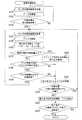
そして、医療支援処理が起動されると、図3に示すように、ロボット制御部40は、その時点での、力検出部30、位置検出部29、及びモーションセンサ34の検知結果を取得する(S110)。すなわち、S110では、ロボット制御部40は、力検出部30で検出したドリルユニット32を移動させる方向、及び移動させる力の大きさと、モーションセンサ34で検知した埋入開始位置と、位置検出部29のそれぞれの検出結果を取得する。そして、ロボット制御部40の制御部42は、各位置検出部29の検出結果に従って、ドリルユニット32の代表位置を特定する。このドリルユニット32の代表位置を特定する方法として、周知の方法で特定したアーム6の先端部の位置に、予め特定されているドリルユニット32の基準位置から代表位置までの長さを加算することが考えられる。The medical support process is activated when an activation command for activating the medical support process is input.
When the medical support process is started, as shown in FIG. 3, the
医療支援処理では、ロボット制御部40は、S110で取得したドリルユニット32を移動させる方向、及び移動させる力の大きさに従ってアーム6を駆動する(S120)。そして、ロボット制御部40は、S110で特定したドリルユニット32の代表位置が、S110で取得した埋入開始位置に一致しているか否かを判定する(S130)。ここで言う一致には、ドリルユニット32の代表位置と埋入開始位置との差分が「0」であることの他に、ドリルユニット32の代表位置と埋入開始位置との差分が「0」とみなせる範囲内となることを含む。 In the medical support process, the
このS130での判定の結果、ドリルユニット32の代表位置が埋入開始位置に一致していなければ(S130:NO)、ロボット制御部40は、医療支援処理をS110へと戻し、ドリルユニット32の代表位置が埋入開始位置に一致するまで、アーム6を駆動する。 As a result of the determination in S130, if the representative position of the
一方、S130での判定の結果、ドリルユニット32の代表位置が埋入開始位置に一致していれば(S130:YES)、ロボット制御部40は、力検出部30、位置検出部29及びモーションセンサ34の検知結果を取得する(S140)。すなわち、S140では、ロボット制御部40は、その時点での、力検出部30で検出したドリルユニット32を術者が移動させる方向、及び移動させる力の大きさと、モーションセンサ34で検知した埋入開始位置と、ドリルユニット32の代表位置とを取得する。 On the other hand, as a result of the determination in S130, if the representative position of the
医療支援処理では、更に、ロボット制御部40は、ドリルユニット32のドリルビットを回転させる(S150)。
続いて、ロボット制御部40は、埋入反力Fを算出してアーム6に付加する(S160)。このS160では、ロボット制御部40は、下記(1)式に示す質量・ばね・ダンパ系の振動モデルに基づいて、埋入反力Fを算出すればよい。In the medical support process, the
Subsequently, the

ただし、(1)式におけるxは、埋入開始位置から埋入領域の内側へのドリルユニット32の代表位置の変位量を表す。xドットは、埋入開始位置から埋入領域の内側へのドリルユニット32の代表位置の変位量の時間微分を表す。xツードットは、埋入開始位置から埋入領域の内側へのドリルユニット32の代表位置の変位量を時間で二階微分したものである。また、符号kは、予め定められたばね係数を表す。符号cは、予め定められた減衰係数を表す。さらに、符号mは、ドリルユニット32の質量を表す。 However, x in the equation (1) represents the amount of displacement of the representative position of the
これにより、S160では、ロボット制御部40は、埋入開始位置から埋入領域の内側への変位量が大きいほど、大きな埋入反力Fをアーム6に付加する。
医療支援処理では、ロボット制御部40は、埋入開始位置の変化量、即ち、患者60の動きが、予め規定された規定量以上であるか否かを判定する(S170)。このS170での判定の結果、患者60の動きが規定量以上であれば(S170:YES)、ロボット制御部40は、詳しくは後述するS200へと医療支援処理を移行させる。Thereby, in S160, the
In the medical support process, the
一方、S170での判定の結果、患者60の動きが規定量未満であれば(S170:NO)、ロボット制御部40は、医療支援処理をS180へと移行させる。そのS180では、ロボット制御部40は、術者によるドリルユニット32の移動方向が、ドリリングの対象となる方向であるか否かを判定する(S180)。ここでいうドリリングの対象となる方向とは、ドリルユニット32を、埋入開始位置から埋入領域の内側へと移動させる方向である。 On the other hand, as a result of the determination in S170, if the movement of the
このS180での判定の結果、ドリルユニット32の移動方向がドリリングの対象となる方向でなければ(S180:NO)、ロボット制御部40は、詳しくは後述するS210へと医療支援処理を移行させる。一方、S180での判定の結果、ドリルユニット32の移動方向がドリリングの対象となる方向であれば(S180:YES)、ロボット制御部40は、医療支援処理をS190へと移行させる。 As a result of the determination in S180, if the movement direction of the
そのS190では、ロボット制御部40は、術者によるドリルユニット32を移動させる力が、予め定められた規定値以上であるか否かを判定する。このS190での判定の結果、ドリルユニット32を移動させる力が規定値以上であれば(S190:YES)、ロボット制御部40は、医療支援処理をS140へと戻す。 In S190, the
一方、S190での判定の結果、ドリルユニット32を移動させる力が規定値未満であれば(S190:NO)、ロボット制御部40は、医療支援処理をS210へと移行させる。 On the other hand, as a result of the determination in S190, if the force for moving the
ところで、S170での判定の結果、患者60の動きが規定量以上である場合に移行されるS200では、ロボット制御部40は、安全制御を実行する。安全制御とは、歯科インプラント治療の安全性を高める制御である。 Meanwhile, as a result of the determination in S170, in S200 that is shifted when the movement of the
具体的に、S200では、ロボット制御部40は、埋入開始位置から埋入領域内へと向かう方向へのアーム6の駆動を停止することを安全制御として実行する。さらに、S200において、ロボット制御部40は、アーム6に付加する埋入反力Fを増加させることを安全制御として実行する。すなわち、S200では、ドリリングの対象となる方向へとアーム6が移動する力を停止し、アーム6に付加する埋入反力Fを増加させる。 Specifically, in S200, the
続くS210では、ロボット制御部40は、埋入反力Fにより、アーム6を、埋入開始位置から埋入領域内へと向かう方向とは反対方向へと移動させる。反対方向とは、埋入開始位置から顎骨62に埋入された場合のインプラント体の軸に沿って、患者60の口腔内へと向かう方向である。 In subsequent S <b> 210, the
さらに、医療支援処理では、ロボット制御部40は、ドリルユニット32の代表位置が埋入開始位置よりも埋入領域の内側であるか否かを判定する(S220)。このS220での判定の結果、ドリルユニット32の代表位置が埋入開始位置よりも埋入領域の内側であれば(S220:YES)、ロボット制御部40は、医療支援処理をS140へと戻す。 Further, in the medical support process, the
一方、S220での判定の結果、ドリルユニット32の代表位置が埋入開始位置よりも埋入領域の外側、即ち、歯科インプラント治療における安全側であれば(S220:NO)、ロボット制御部40は、医療支援処理をS230へと移行させる。 On the other hand, if the result of determination in S220 is that the representative position of the
そのS230では、ロボット制御部40は、アーム6への埋入反力Fの付加を解除する。さらに、S230では、ロボット制御部40は、ドリルユニット32のドリルビットの回転を停止する。 In S230, the
さらに、ロボット制御部40は、予定した埋入深さまでドリリングを終了したか否かを判定する(S240)。このS240では、ロボット制御部40は、ドリリングの終了指令を受け付けた場合に、埋入深さまでドリリングを終了したものと判定すればよい。なお、ドリリングの終了指令は、予め用意されたスイッチが操作されることで受け付ければよい。そのスイッチは、ドリリングが終了した場合に操作される専用のスイッチであってもよいし、その他のスイッチと兼用であってもよい。その他のスイッチの一例としては、歯科医療に用いるドリルユニット32のドリルビットを駆動する駆動スイッチが挙げられる。 Furthermore, the
そして、S240での判定の結果、埋入深さまでドリリングを終了していなければ(S240:NO)、ロボット制御部40は、医療支援処理をS230へと戻す。
一方、S240での判定の結果、埋入深さまでドリリングを終了していれば(S240:YES)、ロボット制御部40は、医療支援処理を終了する。なお、医療支援処理を終了する場合、ロボット制御部40は、ドリルユニット32の先端が器具経路に沿って、患者60の口腔の外へと移動するように制御してもよい。If the result of determination in S240 is that drilling has not been completed to the embedding depth (S240: NO), the
On the other hand, as a result of the determination in S240, if drilling has been completed to the embedding depth (S240: YES), the
つまり、医療支援処理では、図4に示すように、ドリルユニット32を把持した術者が、ドリルユニット32を埋入開始位置から埋入領域の内側に向けて移動させる場合に、その術者による歯科インプラント治療をアーム6の駆動により支援する。 That is, in the medical support process, as shown in FIG. 4, when an operator who holds the
その支援として、図5に示すように、ドリルユニット32のドリルビットが回転され、埋入領域に対応する顎骨62がドリリングされる場合、アーム6に埋入反力Fを加えることを実施する。この埋入反力Fは、埋入開始位置から埋入領域内へと向かう方向とは反対方向の力である。 As the support, as shown in FIG. 5, when the drill bit of the
よって、顎骨62をドリリングするために術者がドリルユニット32を移動させる力が埋入反力Fよりも小さくなると、ドリルユニット32は、埋入反力Fによって顎骨から抜け出易くなる。
[2. 実施形態の効果]
(2.1) 以上説明したように、医療支援装置1を用いる術者は、ドリルユニット32を顎骨62内から容易に抜き出すことができ、患者60に対する安全性を確保しやすくなる。Therefore, when the force for the operator to move the
[2. Effects of the embodiment]
(2.1) As described above, the operator who uses the medical support apparatus 1 can easily extract the
つまり、医療支援装置1によれば、患者60に対する歯科インプラント治療の安全性、ひいては、術者による医療行為の実施の安全性を高めることができる。
(2.2) また、医療支援処理では、ドリルユニット32に埋入反力Fを付加する期間を、ドリルユニット32が、埋入開始位置よりも埋入領域の内側へと移動している期間としている。That is, according to the medical support device 1, the safety of the dental implant treatment for the patient 60, and thus the safety of the medical practice by the operator can be improved.
(2.2) Further, in the medical support process, a period during which the drill reaction force F is applied to the
すなわち、医療支援装置1によれば、歯科インプラント治療において術者がドリリングを実施している際に、ドリルユニット32に埋入反力を加えることができ、患者60に対する歯科インプラント治療の安全性をより高めることができる。 That is, according to the medical support device 1, when an operator is performing drilling in dental implant treatment, an implantation reaction force can be applied to the
(2.3) さらに、医療支援処理では、術者による歯科インプラント治療の実施中に患者60が動いた場合、安全制御を実行している。この安全制御として実行される制御の一つが、開始位置から埋入領域内へと向かう方向へのアーム6の駆動の停止である。 (2.3) Further, in the medical support process, when the patient 60 moves during the dental implant treatment by the operator, safety control is executed. One of the controls executed as the safety control is stopping the driving of the
これにより、医療支援装置1によれば、ドリルユニット32が顎骨62から抜け出ることをよりスムーズに実現できる。
(2.4) また、上記医療支援処理では、安全制御の一つとして、埋入反力Fを増加させることを実行している。Thereby, according to the medical assistance apparatus 1, it can implement | achieve more smoothly that the
(2.4) Moreover, in the said medical assistance process, increasing the implantation reaction force F is performed as one of safety control.
これにより、医療支援装置1によれば、ドリルユニット32が顎骨62から抜け出ることをより早期に実現できる。
これらの結果、医療支援装置1によれば、患者60に対する歯科インプラント治療の安全性をより高めることができる。Thereby, according to the medical assistance apparatus 1, it can implement | achieve earlier that the
As a result, according to the medical support device 1, the safety of dental implant treatment for the patient 60 can be further improved.
(2.5) さらに、医療支援処理では、埋入領域内へのドリルユニット32の埋入の深さが深いほど、即ち、変位量が大きいほど、埋入反力Fの大きさを大きなものとして算出し、アーム6に加えている。これにより、医療支援装置1によれば、顎骨62へのドリルユニット32の進入深さに応じた適切な大きさの埋入反力Fをアーム6に付加できる。 (2.5) Further, in medical support processing, the depth of the embedding reaction force F increases as the depth of embedding of the
(2.6) しかも、医療支援処理においては、質量・ばね・ダンパ系の振動モデルに基づいて、埋入反力Fを算出している。
特に、埋入反力Fの算出式にダンパモデルが組み込まれているため、医療支援装置1によれば、ドリルユニット32を顎骨62から抜く際に、ドリルユニット32の振動を早期に抑制できる。
[3. その他の実施形態]
以上、本発明の実施形態について説明したが、本発明は上記実施形態に限定されるものではなく、本発明の要旨を逸脱しない範囲において、様々な態様にて実施することが可能である。(2.6) Moreover, in the medical support process, the implantation reaction force F is calculated based on a vibration model of mass, spring, and damper system.
In particular, since the damper model is incorporated in the calculation formula for the embedding reaction force F, the medical support device 1 can suppress vibration of the
[3. Other Embodiments]
As mentioned above, although embodiment of this invention was described, this invention is not limited to the said embodiment, In the range which does not deviate from the summary of this invention, it is possible to implement in various aspects.
(3.1) 例えば、上記実施形態の説明に用いた図4,図5では、埋入領域が、下顎骨に位置するものとして説明していたが、埋入領域は、上顎骨に位置していてもよい。
(3.2) 上記実施形態のS160では、質量・ばね・ダンパ系の振動モデルに基づいて埋入反力Fを算出していたが、埋入反力Fの算出方法は、これに限るものではない。例えば、ばね・ダンパ系のモデルに基づいて埋入反力Fを算出してもよいし、ばね系モデルに基づいて埋入反力Fを算出してもよい。さらに言えば、その他の方法で埋入反力Fを算出してもよい。(3.1) For example, in FIGS. 4 and 5 used in the description of the above embodiment, the embedding area is described as being located in the mandible, but the embedding area is located in the maxilla. It may be.
(3.2) In S160 of the above embodiment, the embedded reaction force F is calculated based on the mass / spring / damper vibration model, but the method of calculating the embedded reaction force F is not limited to this. is not. For example, the embedding reaction force F may be calculated based on a spring / damper system model, or the embedding reaction force F may be calculated based on a spring system model. Furthermore, the embedding reaction force F may be calculated by other methods.
(3.3) 上記実施形態において、医療支援装置1は、垂直多関節アームをアーム6として備えていたが、医療支援装置1が備えるアーム6は、これに限るものではない。例えば、医療支援装置1は、水平多関節アームをアーム6として備えていてもよいし、その他のアームをアーム6として備えていてもよい。 (3.3) In the said embodiment, although the medical assistance apparatus 1 was provided with the vertical articulated arm as the
(3.4) 上記実施形態におけるロボット制御部40が実行する機能の一部または全部は、一つあるいは複数のIC等によりハードウェア的に構成されていてもよい。
(3.5) 上記実施形態においては、記憶部50にプログラムが格納されていたが、プログラムを格納する記憶媒体は、これに限るものではなく、半導体メモリなどの非遷移的実体的記憶媒体に格納されていてもよい。(3.4) A part or all of the functions executed by the
(3.5) In the above embodiment, the program is stored in the
(3.6) また、制御部42は非遷移的実体的記録媒体に格納されたプログラムを実行してもよい。このプログラムが実行されることで、プログラムに対応する方法が実現される。 (3.6) Further, the
(3.7) 上記実施形態の構成の一部を省略した態様も本発明の実施形態である。また、上記実施形態と変形例とを適宜組み合わせて構成される態様も本発明の実施形態である。また、特許請求の範囲に記載した文言によって特定される発明の本質を逸脱しない限度において考え得るあらゆる態様も本発明の実施形態である。 (3.7) The aspect which abbreviate | omitted a part of structure of the said embodiment is also embodiment of this invention. Further, an aspect configured by appropriately combining the above embodiment and the modification is also an embodiment of the present invention. Moreover, all the aspects which can be considered in the limit which does not deviate from the essence of the invention specified by the wording described in the claims are the embodiments of the present invention.
(3.8) なお、「特許請求の範囲」及び「課題を解決するための手段」の欄に記載した括弧内の符号は、一つの態様として後述する実施形態に記載の具体的手段との対応関係を示すものであって、本発明の技術的範囲を限定するものではない。 (3.8) It should be noted that the reference numerals in parentheses described in the columns of “Claims” and “Means for Solving the Problems” are the specific means described in the embodiments described later as one aspect. The correspondence relationship is shown and does not limit the technical scope of the present invention.
(3.9) また、本発明は、前述した医療支援装置の他、歯科インプラント治療を支援するためにコンピュータが実行するプログラム、アームの制御方法等、種々の形態で実現することができる。
[4. 対応関係の一例]
医療支援処理のS110,S140を実行することで得られる機能が第1取得部及び第2取得部に相当する。S130,S160,S180,S190,S220を実行することで得られる機能が制御部に相当する。S170,S200を実行することで得られる機能が安全制御部に相当する。(3.9) In addition to the medical support device described above, the present invention can be realized in various forms such as a program executed by a computer to support dental implant treatment, and an arm control method.
[4. Example of correspondence]
The functions obtained by executing S110 and S140 of the medical support process correspond to the first acquisition unit and the second acquisition unit. The function obtained by executing S130, S160, S180, S190, and S220 corresponds to the control unit. The function obtained by executing S170 and S200 corresponds to the safety control unit.
1…医療支援装置 4…基台 6…アーム 8…ベース部 10…上腕部 12…前腕部 14…ハンド取付部 16,18,20,22,24,26…関節部 28…関節アクチュエータ 29…位置検出部 30…力検出部 32…ドリルユニット 34…モーションセンサ 40…ロボット制御部 42…制御部 44…ROM 46…RAM 48…CPU 50…記憶部 60…患者 62…顎骨 DESCRIPTION OF SYMBOLS 1 ... Medical assistance apparatus 4 ...
Claims (9)
Translated fromJapanese前記アームに取り付けられた前記ドリルユニットの代表位置を取得する第1取得部(40,S110,S140)と、
前記歯科インプラント治療に用いるインプラント体が埋入される患者の顎骨内の領域を埋入領域とし、前記顎骨において前記埋入領域の口腔内側の端部を埋入開始位置とし、前記埋入開始位置を取得する第2取得部(40,S110,S140)と、
前記第1取得部で取得したドリルユニットの代表位置が、前記第2取得部で取得した埋入開始位置よりも前記埋入領域内側であれば、前記埋入開始位置から前記埋入領域内へと向かう方向とは反対方向の力である埋入反力が前記ドリルユニットに加わるように前記アームを制御する制御部(40,S130,S160,S180,S190,S220)と
を備える、医療支援装置(1)。An arm (6) to which a drill unit (32) used for dental implant treatment is attached to the tip;
A first acquisition unit (40, S110, S140) for acquiring a representative position of the drill unit attached to the arm;
A region in the jaw bone of a patient in which the implant body used for the dental implant treatment is to be implanted is an implantation region, and an end portion on the inside of the oral cavity of the implantation region in the jaw bone is an implantation start position, A second acquisition unit (40, S110, S140) for acquiring
If the representative position of the drill unit acquired by the first acquisition unit is on the inner side of the embedding area than the embedding start position acquired by the second acquisition unit, the embedding area starts to enter the embedding area. And a control unit (40, S130, S160, S180, S190, S220) for controlling the arm so that an embedding reaction force, which is a force in a direction opposite to the direction of the drill unit, is applied to the drill unit. (1).
前記制御部は、
前記力検出部で前記埋入開始位置から前記埋入領域の内側への力を検出すると、前記埋入反力が前記ドリルユニットに加わるように前記アームを制御する、請求項1に記載の医療支援装置。A force detection unit (30) that is installed at the tip of the arm and detects the force applied to the drill unit;
The controller is
The medical device according to claim 1, wherein when the force detection unit detects a force from the implantation start position to the inside of the implantation region, the arm is controlled so that the implantation reaction force is applied to the drill unit. Support device.
前記力検出部で検出された前記埋入開始位置から前記埋入領域の内側への力が大きいほど、大きな前記埋入反力が前記ドリルユニットに加わるように前記アームを制御する、請求項2に記載の医療支援装置。The controller is
The arm is controlled such that the greater the reaction force applied to the drill unit, the greater the force from the embedding start position detected by the force detection unit to the inside of the embedding area. The medical support apparatus described in 1.
前記制御部は、
前記第2取得部で前記埋入開始位置を繰り返し特定した結果、前記埋入開始位置の変化量が、予め規定された規定量以上であれば、前記歯科インプラント治療の安全性を高める安全制御を実行する安全制御部(40,S170,S200)を、更に備える、請求項1から請求項3までのいずれか一項に記載の医療支援装置。The second acquisition unit repeatedly acquires the embedding start position,
The controller is
As a result of repeatedly specifying the placement start position in the second acquisition unit, if the amount of change in the placement start position is equal to or greater than a predetermined amount, safety control is performed to increase the safety of the dental implant treatment. The medical support device according to any one of claims 1 to 3, further comprising a safety control unit (40, S170, S200) to be executed.
前記埋入開始位置から前記埋入領域内へと向かう方向への前記アームの駆動を停止することを前記安全制御として実行する、請求項4に記載の医療支援装置。The safety controller is
The medical support device according to claim 4, wherein the safety control is executed to stop driving the arm in a direction from the implantation start position toward the implantation region.
前記埋入反力を増加させることを前記安全制御として実行する、請求項4または請求項5に記載の医療支援装置。The safety controller is
The medical support device according to claim 4, wherein increasing the implantation reaction force is executed as the safety control.
前記埋入開始位置から前記埋入領域の内側への前記ドリルユニットの代表位置の変位量に、予め定められたばね係数を乗算した結果に基づいて、前記埋入反力の大きさを特定する、請求項1から請求項6までのいずれか一項に記載の医療支援装置。The controller is
Based on the result of multiplying a displacement amount of the representative position of the drill unit from the embedding start position to the inside of the embedding area by a predetermined spring coefficient, the magnitude of the embedding reaction force is specified. The medical assistance apparatus as described in any one of Claim 1- Claim 6.
前記埋入開始位置から前記埋入領域の内側への前記ドリルユニットの代表位置の変位量に予め定められたばね係数を乗算した結果と、前記変位量の時間微分に予め定められた減衰係数を乗算した結果との和に基づいて、前記埋入反力の大きさを特定する、請求項1から請求項6までのいずれか一項に記載の医療支援装置。The controller is
The result of multiplying the displacement amount of the representative position of the drill unit from the embedding start position to the inside of the embedding region by a predetermined spring coefficient, and the time derivative of the displacement amount are multiplied by a predetermined attenuation coefficient. The medical support device according to any one of claims 1 to 6, wherein a magnitude of the implantation reaction force is specified based on a sum of the obtained results.
前記埋入開始位置から前記埋入領域の内側への前記ドリルユニットの代表位置の変位量に予め定められたばね係数を乗算した結果と、前記変位量の時間微分に予め定められた減衰係数を乗算した結果と、前記変位量の二階微分に前記ドリルユニットの質量を乗算した結果との和に基づいて、前記埋入反力の大きさを特定する、請求項1から請求項6までのいずれか一項に記載の医療支援装置。The controller is
The result of multiplying the displacement amount of the representative position of the drill unit from the embedding start position to the inside of the embedding region by a predetermined spring coefficient, and the time derivative of the displacement amount are multiplied by a predetermined attenuation coefficient. The magnitude of the embedding reaction force is specified based on the sum of the result obtained and the result obtained by multiplying the second-order derivative of the displacement by the mass of the drill unit. The medical support apparatus according to one item.
Priority Applications (2)
| Application Number | Priority Date | Filing Date | Title |
|---|---|---|---|
| JP2016002505AJP6593180B2 (en) | 2016-01-08 | 2016-01-08 | Medical support device |
| US15/393,293US9962232B2 (en) | 2016-01-08 | 2016-12-29 | Medical support device |
Applications Claiming Priority (1)
| Application Number | Priority Date | Filing Date | Title |
|---|---|---|---|
| JP2016002505AJP6593180B2 (en) | 2016-01-08 | 2016-01-08 | Medical support device |
Publications (2)
| Publication Number | Publication Date |
|---|---|
| JP2017121409A JP2017121409A (en) | 2017-07-13 |
| JP6593180B2true JP6593180B2 (en) | 2019-10-23 |
Family
ID=59274854
Family Applications (1)
| Application Number | Title | Priority Date | Filing Date |
|---|---|---|---|
| JP2016002505AExpired - Fee RelatedJP6593180B2 (en) | 2016-01-08 | 2016-01-08 | Medical support device |
Country Status (2)
| Country | Link |
|---|---|
| US (1) | US9962232B2 (en) |
| JP (1) | JP6593180B2 (en) |
Families Citing this family (4)
| Publication number | Priority date | Publication date | Assignee | Title |
|---|---|---|---|---|
| AU2015361139B2 (en) | 2014-12-09 | 2020-09-03 | Biomet 3I, Llc | Robotic device for dental surgery |
| US10905504B2 (en)* | 2015-06-02 | 2021-02-02 | Biomet 3I, Llc | Robotic device for dental surgery |
| CN105395295B (en)* | 2015-11-24 | 2017-05-10 | 张海钟 | Robot system for treating oral cavity and teeth |
| EP3566670A1 (en)* | 2018-05-07 | 2019-11-13 | Koninklijke Philips N.V. | Safety system for surgical robot |
Family Cites Families (21)
| Publication number | Priority date | Publication date | Assignee | Title |
|---|---|---|---|---|
| US3805388A (en)* | 1972-09-05 | 1974-04-23 | Yoshida Seisakusho Kk | Apparatus for holding dental or medical instruments |
| US5343391A (en)* | 1990-04-10 | 1994-08-30 | Mushabac David R | Device for obtaining three dimensional contour data and for operating on a patient and related method |
| US5607303A (en)* | 1994-08-03 | 1997-03-04 | Nakamura; Shoukou | Accessory apparatus of dentistry drills for putting oral cavity organs out of way |
| US6296483B1 (en)* | 1997-03-07 | 2001-10-02 | Universite Joseph Fourier | System for preparing the placing of a dental implant |
| US6322567B1 (en)* | 1998-12-14 | 2001-11-27 | Integrated Surgical Systems, Inc. | Bone motion tracking system |
| US6419484B1 (en)* | 2000-09-12 | 2002-07-16 | The Regents Of The University Of California | Optical coherence tomography guided dental drill |
| EP1219260B1 (en)* | 2000-12-19 | 2003-06-25 | BrainLAB AG | Method and device for dental treatment assisted by a navigation system |
| US6488638B2 (en)* | 2001-03-19 | 2002-12-03 | David R. Mushabac | Dental instrument assembly |
| JP4439812B2 (en)* | 2001-03-26 | 2010-03-24 | エルビー メディカル ゲーエムベーハー | Material excision or material processing method and device system |
| US20020160337A1 (en)* | 2001-04-30 | 2002-10-31 | Michael Klein | Method of using computer data to modify or alter an existing cast or model |
| JP3820390B2 (en)* | 2002-08-26 | 2006-09-13 | 株式会社アイキャット | Artificial root placement position calculation method, artificial root placement position calculation device, computer program, and recording medium |
| US7014461B2 (en)* | 2003-01-23 | 2006-03-21 | Tactile Technologies Llc | Hard tissue surface geometry determination |
| US20060281991A1 (en)* | 2003-05-09 | 2006-12-14 | Fitzpatrick J M | Fiducial marker holder system for surgery |
| US20050186533A1 (en)* | 2004-02-02 | 2005-08-25 | Yechiel Cohen | Computer-controlled dental treatment system and method |
| EP2259746B1 (en) | 2008-04-02 | 2020-02-12 | Neocis, Llc | Guided dental implantation system |
| DE102010031018A1 (en)* | 2010-07-06 | 2012-01-12 | Sirona Dental Systems Gmbh | Method and clamping device for producing a dental surgical template |
| JP6423585B2 (en)* | 2012-10-01 | 2018-11-14 | 株式会社インプラントデント | Dental implant embedding hole forming assist device |
| US9675419B2 (en)* | 2013-08-21 | 2017-06-13 | Brachium, Inc. | System and method for automating medical procedures |
| WO2015137040A1 (en)* | 2014-03-14 | 2015-09-17 | ソニー株式会社 | Robot arm device, robot arm control method and program |
| US9283055B2 (en)* | 2014-04-01 | 2016-03-15 | FPJ Enterprises, LLC | Method for establishing drill trajectory for dental implants |
| US10136968B2 (en)* | 2014-12-24 | 2018-11-27 | Isethco Llc | Disposable surgical intervention guides, methods, and kits |
- 2016
- 2016-01-08JPJP2016002505Apatent/JP6593180B2/ennot_activeExpired - Fee Related
- 2016-12-29USUS15/393,293patent/US9962232B2/ennot_activeExpired - Fee Related
Also Published As
| Publication number | Publication date |
|---|---|
| US20170196654A1 (en) | 2017-07-13 |
| JP2017121409A (en) | 2017-07-13 |
| US9962232B2 (en) | 2018-05-08 |
Similar Documents
| Publication | Publication Date | Title |
|---|---|---|
| JP6593180B2 (en) | Medical support device | |
| JP2017023339A (en) | Medical activity support device | |
| EP3673861B1 (en) | Guided dental implantation system | |
| EP3229723B1 (en) | Robotic device for dental surgery | |
| JP5736596B2 (en) | Method for forming a dental tool | |
| JP6350413B2 (en) | Medical practice support device | |
| KR20130123192A (en) | Robot system for dental implantology and dental implantology procedure using the same | |
| EP1759658A1 (en) | Set of surgical instruments for dental implants | |
| CN113143504A (en) | End effector of oral implantation robot and compliance control method | |
| TW201032780A (en) | System and method for manufacturing a dental implant surgical guide | |
| JP7018399B2 (en) | Treatment support system, treatment support method and treatment support program | |
| JP5119473B2 (en) | Massage robot and its control program | |
| WO2016194325A1 (en) | Medical treatment assistance system | |
| KR20190115342A (en) | A bone-preparation apparatus for implant placement | |
| CN109199614B (en) | Jaw bone positioning and fixing device for navigation positioning and mandible fixing in robot dental implant operation process | |
| JP2017104231A (en) | Medical support device and control method for articulated arm | |
| CN115054390B (en) | Personalized preparation method for guiding planting holes by torque model based on machine learning | |
| JP5097907B2 (en) | Massage robot, its control program, and body part identification robot | |
| JP2022007422A (en) | Dental handpiece system | |
| JP6500708B2 (en) | Medical support device | |
| Yu et al. | Frequency-based analysis of the relationship between cutting force and CT number for an implant-surgery-teaching robot | |
| JP6497299B2 (en) | Medical support device | |
| KR100852572B1 (en) | Dental medical equipment | |
| IT202200027012A1 (en) | TEMPLATE STRUCTURE FOR GUIDED SURGERY ON ZYGOMATIC IMPLANTS FOR DENTAL PROSTHESIS | |
| Cheng et al. | DentiBot: System Design and 6-DoF Hybrid Position/Force Control for Robot-Assisted Endodontic Treatment |
Legal Events
| Date | Code | Title | Description |
|---|---|---|---|
| A621 | Written request for application examination | Free format text:JAPANESE INTERMEDIATE CODE: A621 Effective date:20180409 | |
| A977 | Report on retrieval | Free format text:JAPANESE INTERMEDIATE CODE: A971007 Effective date:20190228 | |
| A131 | Notification of reasons for refusal | Free format text:JAPANESE INTERMEDIATE CODE: A131 Effective date:20190319 | |
| TRDD | Decision of grant or rejection written | ||
| A01 | Written decision to grant a patent or to grant a registration (utility model) | Free format text:JAPANESE INTERMEDIATE CODE: A01 Effective date:20190827 | |
| A61 | First payment of annual fees (during grant procedure) | Free format text:JAPANESE INTERMEDIATE CODE: A61 Effective date:20190909 | |
| R151 | Written notification of patent or utility model registration | Ref document number:6593180 Country of ref document:JP Free format text:JAPANESE INTERMEDIATE CODE: R151 | |
| LAPS | Cancellation because of no payment of annual fees |