JP6591664B2 - Embolization removal device - Google Patents
Embolization removal deviceDownload PDFInfo
- Publication number
- JP6591664B2 JP6591664B2JP2018513626AJP2018513626AJP6591664B2JP 6591664 B2JP6591664 B2JP 6591664B2JP 2018513626 AJP2018513626 AJP 2018513626AJP 2018513626 AJP2018513626 AJP 2018513626AJP 6591664 B2JP6591664 B2JP 6591664B2
- Authority
- JP
- Japan
- Prior art keywords
- removal device
- thrombus
- embolus removal
- connectors
- embolus
- Prior art date
- Legal status (The legal status is an assumption and is not a legal conclusion. Google has not performed a legal analysis and makes no representation as to the accuracy of the status listed.)
- Active
Links
Images


Classifications
- A—HUMAN NECESSITIES
- A61—MEDICAL OR VETERINARY SCIENCE; HYGIENE
- A61B—DIAGNOSIS; SURGERY; IDENTIFICATION
- A61B17/00—Surgical instruments, devices or methods
- A61B17/22—Implements for squeezing-off ulcers or the like on inner organs of the body; Implements for scraping-out cavities of body organs, e.g. bones; for invasive removal or destruction of calculus using mechanical vibrations; for removing obstructions in blood vessels, not otherwise provided for
- A61B17/221—Gripping devices in the form of loops or baskets for gripping calculi or similar types of obstructions
- A—HUMAN NECESSITIES
- A61—MEDICAL OR VETERINARY SCIENCE; HYGIENE
- A61B—DIAGNOSIS; SURGERY; IDENTIFICATION
- A61B17/00—Surgical instruments, devices or methods
- A61B17/22—Implements for squeezing-off ulcers or the like on inner organs of the body; Implements for scraping-out cavities of body organs, e.g. bones; for invasive removal or destruction of calculus using mechanical vibrations; for removing obstructions in blood vessels, not otherwise provided for
- A61B17/22031—Gripping instruments, e.g. forceps, for removing or smashing calculi
- A61B2017/22034—Gripping instruments, e.g. forceps, for removing or smashing calculi for gripping the obstruction or the tissue part from inside
- A—HUMAN NECESSITIES
- A61—MEDICAL OR VETERINARY SCIENCE; HYGIENE
- A61B—DIAGNOSIS; SURGERY; IDENTIFICATION
- A61B17/00—Surgical instruments, devices or methods
- A61B17/22—Implements for squeezing-off ulcers or the like on inner organs of the body; Implements for scraping-out cavities of body organs, e.g. bones; for invasive removal or destruction of calculus using mechanical vibrations; for removing obstructions in blood vessels, not otherwise provided for
- A61B17/221—Gripping devices in the form of loops or baskets for gripping calculi or similar types of obstructions
- A61B2017/2215—Gripping devices in the form of loops or baskets for gripping calculi or similar types of obstructions having an open distal end
- A—HUMAN NECESSITIES
- A61—MEDICAL OR VETERINARY SCIENCE; HYGIENE
- A61F—FILTERS IMPLANTABLE INTO BLOOD VESSELS; PROSTHESES; DEVICES PROVIDING PATENCY TO, OR PREVENTING COLLAPSING OF, TUBULAR STRUCTURES OF THE BODY, e.g. STENTS; ORTHOPAEDIC, NURSING OR CONTRACEPTIVE DEVICES; FOMENTATION; TREATMENT OR PROTECTION OF EYES OR EARS; BANDAGES, DRESSINGS OR ABSORBENT PADS; FIRST-AID KITS
- A61F2/00—Filters implantable into blood vessels; Prostheses, i.e. artificial substitutes or replacements for parts of the body; Appliances for connecting them with the body; Devices providing patency to, or preventing collapsing of, tubular structures of the body, e.g. stents
- A61F2/01—Filters implantable into blood vessels
- A61F2/011—Instruments for their placement or removal
- A—HUMAN NECESSITIES
- A61—MEDICAL OR VETERINARY SCIENCE; HYGIENE
- A61F—FILTERS IMPLANTABLE INTO BLOOD VESSELS; PROSTHESES; DEVICES PROVIDING PATENCY TO, OR PREVENTING COLLAPSING OF, TUBULAR STRUCTURES OF THE BODY, e.g. STENTS; ORTHOPAEDIC, NURSING OR CONTRACEPTIVE DEVICES; FOMENTATION; TREATMENT OR PROTECTION OF EYES OR EARS; BANDAGES, DRESSINGS OR ABSORBENT PADS; FIRST-AID KITS
- A61F2/00—Filters implantable into blood vessels; Prostheses, i.e. artificial substitutes or replacements for parts of the body; Appliances for connecting them with the body; Devices providing patency to, or preventing collapsing of, tubular structures of the body, e.g. stents
- A61F2/01—Filters implantable into blood vessels
- A61F2002/016—Filters implantable into blood vessels made from wire-like elements
Landscapes
- Health & Medical Sciences (AREA)
- Life Sciences & Earth Sciences (AREA)
- Surgery (AREA)
- Heart & Thoracic Surgery (AREA)
- Public Health (AREA)
- Vascular Medicine (AREA)
- Engineering & Computer Science (AREA)
- Biomedical Technology (AREA)
- Veterinary Medicine (AREA)
- General Health & Medical Sciences (AREA)
- Animal Behavior & Ethology (AREA)
- Molecular Biology (AREA)
- Medical Informatics (AREA)
- Nuclear Medicine, Radiotherapy & Molecular Imaging (AREA)
- Orthopedic Medicine & Surgery (AREA)
- Surgical Instruments (AREA)
- Cardiology (AREA)
- Oral & Maxillofacial Surgery (AREA)
- Transplantation (AREA)
Description
Translated fromJapanese本明細書に開示される発明は、一般に、脈管構造から塞栓性閉塞を除去するように構成された医療装置に関する。 The invention disclosed herein generally relates to medical devices configured to remove embolic obstructions from the vasculature.
血栓、塞栓または血塊が人の血管系に発生することがある。ときには、そのような血栓が害を及ぼすことなく血流に溶解することもある。しかしながら、またあるときは、そのような血栓が血管内に留まり、そこで血液の流れを部分的または完全に塞ぐことがあり、それは虚血性事象と呼ばれる。部分的または完全に閉塞した血管が、脳、肺または心臓などの傷付きやすい組織に血液を供給すると、深刻な組織損傷が生じる可能性がある。また、そのような虚血性事象は、アテローム性動脈硬化症、すなわち、血管を狭くし、かつ/または蛇行させる血管疾患によって、悪化することもある。血管の狭窄および/または蛇行の増加は、状況によっては、アテローム性動脈硬化性プラークを形成して、さらなる合併症を引き起こす可能性もある。 Thrombus, emboli or blood clots can develop in a person's vasculature. Sometimes such thrombi dissolve into the bloodstream without harm. However, at other times, such a thrombus may remain in the blood vessel where it partially or completely occludes blood flow, which is called an ischemic event. Serious tissue damage can occur when partially or completely occluded blood vessels supply blood to vulnerable tissues such as the brain, lungs, or heart. Such ischemic events may also be exacerbated by atherosclerosis, a vascular disease that causes the blood vessels to narrow and / or meander. In some circumstances, stenosis of the blood vessels and / or increased meandering can form atherosclerotic plaques and cause further complications.
公知の塞栓除去装置は、血管から血栓またはその他の異物を除去するために様々な用途で使用される。そのような装置には、引用により全体が本明細書に援用されるGrandfieldの米国特許第8,529,596号に記載および説明されるような円筒形骨格の塞栓除去装置が含まれる。 Known emboli removal devices are used in a variety of applications to remove blood clots or other foreign objects from blood vessels. Such devices include cylindrical skeleton embolus removal devices such as those described and illustrated in Grandfield, US Pat. No. 8,529,596, which is hereby incorporated by reference in its entirety.
図1Aおよび図1Bは、Stryker社のNeurovascular Intervention部門(http://www.stryker.com/en−us/products/NewurovascularIntervention/index.htm)により製造販売されている例示的な従来の塞栓除去装置12を示している。図1Aは塞栓除去装置12を二次元の平面図で示し、図1Bは当該装置12の三次元の拡張した管状形態を示している。塞栓除去装置12は、自己拡張可能で生体適合性の形状記憶材料、例えばニチノールで構成されている。塞栓除去装置12は、好ましくは、形状記憶材料のチューブまたはシートをレーザ切断することによって製造される。塞栓除去装置12は、当該装置12から近位方向に延びる細長い可撓性ワイヤ40に連結され、このワイヤ40が、血管内の標的部位にシースおよび/またはカテーテルを介して塞栓除去装置12を押し込み、かつ引っ張るように構成されている。 1A and 1B are exemplary removal plugs manufactured and sold by Stryker's Neurovascular Intervention Department (http://www.stryker.com/en-us/products/Neurovascular Intervention / index.htm). 12 is shown. FIG. 1A shows the
図1Aに示すように、塞栓除去装置12は、近位端部分14と、本体部分16と、遠位端部分18とを含み、本体部分が、複数の長手方向波状要素24(例えば、ワイヤ、ストラット)を含み、隣接する波状要素が、互いに位相がずれており、当該装置のそれぞれの近位端部分と遠位端部分の間に延在する複数の斜めに配置されたセル構造26を形成するように連結されている。塞栓除去装置12の本体部分16および遠位端部分18のセル構造26は、装置12の長手方向軸30の周囲に連続的にかつ周方向に延在している(図1Aおよび図1B)。 As shown in FIG. 1A, the
特に、近位端部分14のセル構造26は、装置12の長手方向軸30の周りを周方向に延びているとはいえない。本体部分16のセル構造26の寸法および材料特性は、十分な半径方向の力(例えば、単位長さ当たりの半径方向の力が0.005N/mm−0.050N/mm、好ましくは0.030N/mm−0.050N/mm)および接触相互作用をもたらし、それにより、患者から塞栓性閉塞を部分的または完全に除去すべく、セル構造26および/または要素24を血管系内に存在する塞栓性閉塞と係合させるように選択されている。図1Bに最もよく示されているように、塞栓除去装置12は、約32ミリメートルの全体長さL1を有し、本体部分16の長さL2が約20ミリメートルである。通常、本体部分16の長さは、近位端部分14の長さの約2.5倍〜約3.5倍である。 In particular, the
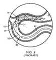
図2は、塞栓性閉塞または血栓75を捕捉するために患者の蛇行する血管構造の標的部位に配置された図1Aおよび図1Bの塞栓除去装置12を示している。塞栓除去装置12が送達カテーテル80内に配置されるときなど、未拡張の形態または半径方向に圧縮された形態(図示省略)では、塞栓除去装置12は0.4−0.7ミリメートルの未拡張外径(UOD)を有する。半径方向に拡張された形態(図1Bおよび図2)では、塞栓除去装置12は、2.5−5.0ミリメートルの拡張外径(EOD)を有する。塞栓除去装置12は、十分な半径方向の力および接触相互作用をもたらし、それにより、ストラット要素24および/またはセル構造26が、血管70内に位置する塞栓性閉塞75と係合し、閉塞を捕らえ、封入し、捕捉し、挟み込み、かつ/または閉じ込め、患者からの塞栓性閉塞75の除去を可能にする。完全に拡張した形態における本体部分16の直径は、約4.0ミリメートルであり、セルパターン、要素24の寸法および材料は、本体部分の直径が1.0ミリメートル−1.5ミリメートルに減少したときに0.040N/mm−0.050N/mmの半径方向の力を生じるように選択される。セルパターン26、ストラット24の寸法および材料は、本体部分16の直径が3.0ミリメートルに減少したときに、0.010N/mm−0.020N/mmの半径方向の力を生成するように選択される。ストラットの厚さ対幅の比が1より大きい場合、塞栓性閉塞75へのストラット要素24の一体化が促進される。 FIG. 2 shows the
塞栓除去装置12の製造に使用される技術に拘わらず、ストラット要素24を相互に接続する方法が、装置の長手方向および半径方向の剛性および柔軟性を決定する。血栓または塞栓性閉塞75と係合するのに必要な半径方向の力を提供するには、半径方向の剛性が必要であるが、標的部位への送達のために装置12の半径方向の圧縮を容易にするには、半径方向の柔軟性が必要である。血管70から係合した血栓または塞栓性閉塞75を引き出すには、長手方向の剛性が必要であるが、(例えば、蛇行する血管系を介した)装置12の送達を容易にするには、長手方向の柔軟性が必要である。塞栓除去装置12のパターンは、典型的には、装置12の長手方向および半径方向の剛性と柔軟性との間の最適なバランスを維持するように設計される。しかしながら、特定の用途では、塞栓除去装置12を血管70内に展開した後に、装置12が引き出しまたは取り出しのために張力/力を受けると、装置12、特に本体部分16が、伸びて、上述した非拡張外形(UOD)(例えば、0.4−0.7ミリメートル)と同様に、より小さい外形または外径(OD)を形成しやすい。 Regardless of the technique used to manufacture the
図3Aは、カテーテル80よりも遠位側に位置する血管70内に配置された、より小さい外形/ODを有する図1A、図1Bおよび図2の塞栓除去装置12を示している。装置12の伸びおよびより小さい外形/ODによって、図3Aおよび図3Dに示すように、塞栓性閉塞75と係合することなく、または塞栓性閉塞を捕捉することなく、閉塞75を通り過ぎて装置12の引き抜きが生じる可能性がある。図3B−図3Dは、塞栓性閉塞75が内部にある管腔72を有する血管70の断面図である。血管腔72から塞栓性閉塞75を除去するための塞栓摘出術では、送達カテーテル80の遠位部分が閉塞75に隣接する標的部位に配置されるまで、図3Cに示すように、半径方向に圧縮された塞栓除去装置12がカテーテル80内に配置された状態で、カテーテル80が管腔72を通って進められる。その後、カテーテル80から血管腔72内に装置12を展開するために、塞栓除去装置12がカテーテル80に対して遠位方向に押し込まれるか、あるいはカテーテル80が塞栓除去装置12(またはそれぞれの一部)に対して近位方向に引き込まれ、それにより、半径方向の拘束から解放された塞栓除去装置12が血管腔72内で半径方向に拡張して、閉塞75と係合し、閉塞を捕獲および捕捉することが可能となる。 FIG. 3A shows the
しかしながら、特定の場合(例えば、硬質/高密度の塞栓性閉塞75)には、塞栓除去装置12の半径方向の拡張力33が、塞栓性閉塞75の硬さおよび抵抗力36に打ち勝って装置12のストラットを血栓75内に進入させて血栓と一体化させるのに十分ではなく、その代わりに、図3Dに示すように、装置12が閉塞75の周囲に延びて最も抵抗の少ない経路を通るようになる。閉塞75の周囲に延びるときの装置12の望ましくない細長い外形/ODは、装置12を引き抜くときに閉塞75と係合することなく、あるいは閉塞を捕獲または捕捉することなく、塞栓性閉塞75を通り過ぎることになりやすい。 However, in certain cases (eg, hard / high density embolic occlusion 75), the
このため、装置の再配置および/または引き込みのために再び収めるときに外形/ODの望ましい縮小を可能としながらも、血管内に展開して張力を受けるときに塞栓除去装置の外形/ODの望ましくない伸び、伸長および/または縮小を防止する必要性が存在する。 For this reason, it is desirable to reduce the profile / OD of the embolus removal device when deployed into a blood vessel and under tension while allowing the desired reduction of the profile / OD when retracted for device repositioning and / or retraction. There is a need to prevent not stretching, stretching and / or shrinking.
開示の発明の例示的な実施形態では、塞栓除去装置が、内側ルーメンを有するオープンセル構造を形成する複数の相互接続されたストラットを含む血栓係合構造体であって、送達カテーテルから血管内に放出されたときに、半径方向に拘束された形態から半径方向に拡張した形態に拡張するようにバイアスされているか又は拡張可能である血栓係合構造体と、前記血栓係合構造体の内側ルーメン内に位置する支持構造体であって、前記血栓係合構造体のそれぞれのストラットに連結された複数のコネクタを有する支持構造体とを含み、前記支持構造体のコネクタが、前記血栓係合構造体が送達カテーテルから血管内に放出されたときに、半径方向に拘束された形態から半径方向に拡張した形態に移動するようにバイアスされているか又は移動可能であり、それにより、前記血栓係合構造体の拡張を引き起こすか、または補助し、かつ/または促すようになっている。 In an exemplary embodiment of the disclosed invention, an embolus removal device is a thrombus engagement structure that includes a plurality of interconnected struts forming an open cell structure having an inner lumen, from a delivery catheter into a blood vessel. A thrombus-engaging structure that is biased or expandable to expand from a radially constrained configuration to a radially expanded configuration when released, and an inner lumen of said thrombus-engaging structure And a support structure having a plurality of connectors coupled to respective struts of the thrombus engaging structure, wherein the connector of the support structure includes the thrombus engaging structure. Biased or moved to move from a radially constrained configuration to a radially expanded configuration when the body is released into the blood vessel from the delivery catheter An ability, thereby, so that either cause extension of the thrombus engagement structure, or auxiliary, and / or urge.
幾つかの実施形態では、前記支持構造体が、前記血栓係合構造体のルーメンを少なくとも部分的に通って延び、かつルーメンに対して移動可能な細長い中央支持部材をさらに備え、前記複数のコネクタのうちの各コネクタが、前記中央支持部材に連結された第1端部と、前記血栓係合構造体のそれぞれのストラットに連結された第2端部とを有する。そのような実施形態では、前記複数のコネクタの第1端部を、前記中央支持部材に沿って、軸方向および/または周方向にオフセットしたそれぞれの位置で前記中央支持部材に接続することができる。血栓を係合させた後に前記支持構造体がカテーテル内への前記血栓係合構造体の回収を妨げることのないように、前記コネクタは、好ましくは、当該コネクタよりも近位側に延在する中央支持部材のセグメントと鈍角をなしており、すなわち、前記支持構造体が半径方向に拡張された形態にあるときよりも、前記支持構造体が半径方向に拘束された形態にあるときの方が、それぞれのコネクタと前記中央支持部材との間に形成される鈍角が大きくなる。 In some embodiments, the support structure further comprises an elongated central support member that extends at least partially through the lumen of the thrombus-engaging structure and is movable relative to the lumen, the plurality of connectors Each connector has a first end connected to the central support member and a second end connected to a respective strut of the thrombus engaging structure. In such an embodiment, the first ends of the plurality of connectors can be connected to the central support member at respective positions offset in the axial direction and / or circumferential direction along the central support member. . The connector preferably extends proximally relative to the connector so that the support structure does not interfere with retrieval of the thrombus engaging structure into the catheter after the thrombus is engaged. It forms an obtuse angle with the segment of the central support member, i.e. when the support structure is in a radially constrained configuration rather than when the support structure is in a radially expanded configuration. The obtuse angle formed between each connector and the central support member is increased.
代替的な実施形態では、中央支持部材は設けられておらず、その代わりに、前記複数のコネクタのうちの各コネクタが、前記血栓係合構造体のそれぞれの第1のストラットに接続された第1端部と、前記血栓係合構造体のそれぞれの第2のストラットに接続された第2端部とを有する。そのような実施形態では、前記コネクタのうちの1またはそれ以上が、それぞれの中間点で、一定の角度を形成する。特に、前記コネクタの1またはそれ以上のそれぞれの中間部分は、前記血栓係合構造体に対するそれぞれのコネクタのヒンジのような動作を可能にする、柔軟部分、屈曲点、リビングヒンジまたはその他の適切なジョイントを含むことができる。 In an alternative embodiment, no central support member is provided, instead each connector of the plurality of connectors is connected to a respective first strut of the thrombus engagement structure. One end and a second end connected to each second strut of the thrombus-engaging structure. In such an embodiment, one or more of the connectors form a certain angle at each midpoint. In particular, one or more respective intermediate portions of the connector may be flexible portions, bend points, living hinges or other suitable portions that allow the respective connector hinge-like operation relative to the thrombus-engaging structure. Joints can be included.
なお、支持構造体の開示の実施形態を血栓回収装置に組み込むことは、血栓回収構造体のストラットの半径方向の拡張を引き起こし、補助し、かつ/または促すのみならず、特に、ストラット間に形成されるセルの開放を促し、特に血栓が硬化して支持構造体がなければセルの崩れを引き起こすような場合においても、血栓物質をより良好に係合/捕捉するようにセルを開放した状態で維持することを理解されたい。 It should be noted that incorporating the disclosed embodiment of the support structure into the thrombectomy device not only causes, assists and / or facilitates radial expansion of the struts in the thrombectomy structure, but especially forms between the struts. In the open state to better engage / capture the thrombotic material, especially in cases where the thrombus hardens and causes the cell to collapse without the support structure. Please understand to maintain.
開示の発明の実施形態のその他のおよび更なる態様および特徴は、添付図面を考慮して、次の詳細な説明から明らかになるであろう。 Other and further aspects and features of embodiments of the disclosed invention will become apparent from the following detailed description, taken in conjunction with the accompanying drawings.
以下の定義された用語については、本明細書のその他の箇所または特許請求の範囲に異なる定義が与えられない限りは、それら定義が適用される。 For the following defined terms, these definitions shall be applied, unless a different definition is given elsewhere in this specification or in the claims.
本明細書において、全ての数値は、明示されているか否かに関わらず、用語「約」によって修飾されるものとする。用語「約」は、一般に、記載の値に同等と当業者が考える数の範囲(すなわち、同じ作用または結果を有する範囲)を指している。多くの場合、用語「約」は、最も近い有効数字に四捨五入された数を含むことができる。終点による数的範囲の記述は、その範囲内のすべての数を含む(例えば、1−5は、1,1.5,2,2.75,3,3.80,4および5を含む)。本明細書および添付の特許請求の範囲において、単数形「a」、「an」および「the」は、それ以外の明示が無い限りは、複数の指示対象を含む。本明細書および添付の特許請求の範囲において、用語「or」(または)は、それ以外の明示が無い限りは、「and/or」(および/または)を含む意味で一般に用いられる。 In this specification, all numerical values shall be modified by the term “about”, whether or not explicitly stated. The term “about” generally refers to a range of numbers that one skilled in the art would equate to a stated value (ie, a range having the same effect or result). In many cases, the term “about” can include numbers rounded to the nearest significant figure. The description of a numerical range by endpoint includes all numbers within that range (eg 1-5 includes 1,1.5, 2, 2.75, 3, 3.80, 4 and 5). . In this specification and the appended claims, the singular forms “a”, “an”, and “the” include plural referents unless explicitly stated otherwise. In this specification and the appended claims, the term “or” (or) is generally used in its sense including “and / or” (and / or) unless stated otherwise.
以下に、図面を参照しながら、開示の発明の様々な実施形態を説明する。なお、図面は必ずしも同じ縮尺では描かれておらず、選択要素の相対的な縮尺は明確化のために誇張されており、また、同様の構造または機能の構成要素は、図面全体を通じて同様の符号により表されていることに留意されたい。また、図面は、実施形態の説明を容易にすることのみを目的としており、本発明の包括的な記述または発明の範囲の限定を意図したものではなく、本発明の範囲は、添付の特許請求の範囲のみによって規定されることにも留意されたい。さらに、開示の発明の例示的な実施形態は、開示の態様または利点すべてを含む必要はない。開示の発明の特定の実施形態とともに記載される態様または利点は、その実施形態に必ずしも限定されるものではなく、その他の実施形態において、そのように記載されていなくとも、実施し得るものである。 Hereinafter, various embodiments of the disclosed invention will be described with reference to the drawings. Note that the drawings are not necessarily drawn to the same scale, the relative scales of selected elements are exaggerated for clarity, and components of similar structure or function are denoted by the same reference numerals throughout the drawings. Note that is represented by. Also, the drawings are only for the purpose of facilitating the description of the embodiments and are not intended to be a comprehensive description of the invention or to limit the scope of the invention, the scope of the invention being defined by the appended claims. Note also that it is defined only by the scope of Moreover, example embodiments of the disclosed invention need not include all disclosed aspects or advantages. An aspect or advantage described with a particular embodiment of the disclosed invention is not necessarily limited to that embodiment, and may be practiced in other embodiments even if not so described. .
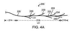
図4A−図4Eは、開示の発明の一実施形態に従って構成された塞栓除去装置の支持構造体200を示している。この支持構造体200は、そこから延びる複数の要素230を有する細長い中央部材220を含む。中央部材220は、近位端部分214と、本体部分216と、遠位端部分218とを含む。延出要素230は、中央部材220に連結されたそれぞれ第1端部232(図4A−図4Cおよび図5)と、塞栓除去装置112のストラット要素124に連結されたそれぞれの第2端部234(図5)と、第1端部と第2端部との間に延在するそれぞれの中間部分233(図4A−図4Cおよび図5)とを有する。延出要素230の第1端部232は、中央部材220に対する延出要素230のヒンジのような動作を可能にする、柔軟部分、屈曲点、リビングヒンジまたはその他の適切なジョイントを含むことができる。 4A-4E illustrate an embolus removal
図4A−図4Cの延出要素230は、細長い中央部材220の長さL3に沿って交互に配置され、葉脈のように、それぞれの第1端部232が、第2端部234よりも近位側に配置されている。延出要素230は、図4A−図4Cに示すように、それぞれの第1端部232からそれぞれの第2端部234に延びる凹状の湾曲(例えば、正の単極性の凹状の滑らかな湾曲)をさらに含むことができる。延出要素230は、円形(図4D)、楕円形(図4E)またはその他の適切な断面形状を含むことができる。延出要素230の断面形状は、第1端部232から第2端部234まで連続的な形状であってもよく、あるいはその長さに沿って変化してもよいことを理解されたい。例えば、延出要素230の断面形状は、第1端部232および第2端部234において円形とし、中間部分233において楕円形とすることができる。 The
支持構造体200は、単一構成要素(例えば、円筒構造またはシートのレーザ切断、3D印刷、押出成形など)で形成されるようにしても、あるいは互いに溶接、接着またはその他の方法で結合された別個の構成要素を含むようにしてもよい。例えば、延出要素230は、ヒンジのような形で中央部材220に結合されるものであってもよい。支持構造体200は、複数の延出要素230が半径方向に拘束された送達形態(図4A)と、複数の要素230が半径方向に拡張された展開形態(図4B)とを有する。延出要素230は、中央部材220に対して角度「A」で配置されている。例えば、延出要素230の角度は、10°(A1−図4A)〜75°(A2−図4A)の範囲とすることができるが、その他の適切な角度も考えられる。延出要素230は、図4Bに示すように、外側に向かって拡張するようにバイアスすることができる。 The
支持構造体200は、数多くの生体適合性材料、圧縮可能な材料、弾性材料またはそれらの組み合わせから構成することができ、それには、ポリマー材料、金属および金属合金、例えば、ステンレス鋼、タンタル、またはニチノールとして知られている超弾性ニッケルチタン合金のようなニッケルチタン合金が含まれる。支持構造体200は、放射線不透過性マーカを含むことができ、あるいは放射線不透過性材料の層でコーティングすることができる。中央部材220および延出要素230を含む支持構造体200は、代替的な形状およびその他の適切な構成を有することができることを理解されたい。図6および図8に示す例示的な構成のように、延出要素230の構成(例えば、位置、形状、材料)など、支持構造体200のその他の変形例も考えられる。本明細書において、「支持構造体」という用語は、1またはそれ以上の構成要素が直接的または間接的に結合、固着または固定される任意のデバイスまたは構成要素を指している。さらに、本明細書において、「結合された」という用語は、1またはそれ以上の構成要素が、直接的または間接的に取り付けられ、固定され、またはその他の方法で連結されることを指している。 The
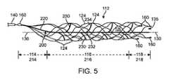
図5は、開示の発明に係る図4A−図4Cの支持構造体を有する塞栓除去装置の斜視図である。塞栓除去装置112は、複数の細長いストラット要素124によって形成された円筒形骨格を含む。ストラット要素124は、複数の長手方向波状要素とすることができ、隣接する波状要素のセットは、互いに位相がずれており、複数の斜めに配置されたセル構造126を形成するように相互に連結されている。塞栓除去装置112は、近位端部分114と、本体部分116と、遠位端部分118と、近位端部分114から遠位端部分118まで延在するルーメン135とを含む。塞栓除去装置112は、当該装置112から近位側に延びる細長い可撓性ワイヤ140に連結されており、このワイヤ140が、シースおよび/またはカテーテルを介して血管内の標的部位に塞栓除去装置112を押し込み、かつ引き込むように構成されている。塞栓除去装置112は、1またはそれ以上の放射線不透過性マーカ160を含む。 FIG. 5 is a perspective view of an embolus removal device having the support structure of FIGS. 4A-4C according to the disclosed invention. The
セル構造126は、装置112の長手方向軸130の周りに連続的にかつ周方向に延在する。本体部分116のストラット要素124および/またはセル構造126の寸法および材料特性は、十分な半径方向の力(例えば、単位長さ当たりの半径方向の力が0.005N/mm−0.050N/mm、好ましくは0.030N/mm−0.050N/mm)および接触相互作用をもたらし、それにより、セル構造126および/または要素124を血管系内に存在する塞栓性閉塞と係合させて、患者から塞栓性閉塞を部分的または完全に除去できるように選択されている。 The cell structure 126 extends continuously and circumferentially about the
塞栓除去装置112は、様々な技術を使用して、ワイヤから織り込み、チューブから切り出し、またはシートから切り出すことができ、そのような技術には、レーザ切断や、チューブまたはシートにパターンをエッチングして残りの材料からストラットを形成するもの、あるいはその他の適切な技術が含まれる。塞栓除去装置112は、数多くの生体適合性材料、圧縮可能な材料、弾性材料またはそれらの組み合わせから構成することができ、それには、ポリマー材料、金属および金属合金、例えば、ステンレス鋼、タンタル、またはニチノールとして知られている超弾性ニッケルチタン合金のようなニッケルチタン合金が含まれる。 The
図5に示すように、塞栓除去装置112は、図4A−図4Cの支持構造体200を含む。支持構造体200は、塞栓除去装置112のルーメン135内に配置される。一実施形態では、支持構造体200の中央部材220が、塞栓除去装置112の長手方向軸130に沿って配置される。支持構造体200、特に中央部材220の近位端部分214は、ワイヤ140に連結される一方、それぞれの延出要素230の第2端部234は、それぞれのストラット要素124に連結されている。支持構造体200は、塞栓除去装置112に対して適切な支持を提供し、装置の望ましくない小さな外形/OD(図3)を形成する引っ張り力、引き抜き力または引き戻し力を受ける間に、装置112の伸びを防止する。引っ張り力、軸方向の引き抜き力または引き戻し力がワイヤ140を介して塞栓除去装置112に加えられると、そのような力は、塞栓除去装置112の支持構造体200とストラット要素124との間に分散される。 As shown in FIG. 5, the
一実施形態では、引っ張り力、引き抜き力または引き戻し力の大部分が、ストラット要素124ではなく、支持構造体200に伝達されて、塞栓除去装置112が展開形態を保持するのを補助し、装置112の伸びおよび望ましくない小さい外形/OD(例えば、閉塞と係合することなく、あるいは閉塞を捕獲または捕捉することなく、塞栓性閉塞を通過すること)を防止する。さらに、遠位方向に延びる凹状の湾曲を有する延出要素230が設けられた支持構造体200を含む塞栓除去装置112(図4A−図4Bおよび図5)は、当該装置112が再配置および/または引き出しのために再び収められるときなどに、外形/ODの望ましい減少を可能にする。 In one embodiment, most of the pulling, pulling or pulling force is transmitted to the
図6Aおよび図7は、開示の発明の別の実施形態に従って構成された塞栓除去装置の支持構造体を示している。説明を容易にするために、図4A−図4Eの支持構造体200と同じ支持構造体200’の特徴、機能および構成には、同様の符号を与えている。支持構造体200’は、細長い中央部材220を含み、この中央部材が、そこから延出する複数の要素230を有する。延出部材230は、中央部材220に沿って交互に配置されている。一実施形態では、細長い部材230が、中心部材220に沿って交互にかつ放射状に配置され、図6Aおよび図7の斜視図では、細長い部材230’の一部をより短く見せている。細長い部材230’は、図6Bに示す支持構造体200’の断面図に最も良く示されるように、細長い部材230とほぼ同じ長さである。別の実施形態では、細長い中央部材220は、中央部材220に沿って交互に配置された、複数の長い延出要素230および複数の短い延出要素230’’を含む(図示省略)。 6A and 7 show a support structure for an embolus removal device constructed in accordance with another embodiment of the disclosed invention. For ease of explanation, features, functions and configurations of the same support structure 200 'as the
支持構造体200’は、近位部分244および遠位部分248を備える。延出要素230/230’は、中央部材220に沿って交互にかつ順次配置され、近位部分244では延出要素230がより少なく、遠位部分248では延出要素がより多くなっており、その結果、塞栓除去装置112は、遠位部分においてより大きな支持を有し、それにより、装置112の伸びおよび望ましくない小さい外形/OD(例えば、閉塞と係合することなく、あるいは閉塞を捕獲または捕捉することなく、塞栓性閉塞を通過すること)を防止する。
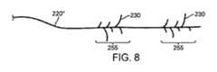
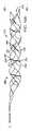
図8および図9は、開示の発明のさらに別の実施形態に従って構成された塞栓除去装置の支持構造体を示している。説明を容易にするために、図4A−図4Eの支持構造体200および/または図6A、図6Bおよび図7の支持構造体200’と同じ支持構造体200’’の特徴、機能および構成には、同様の符号を与えている。支持構造体200’’は、細長い中央部材220を含み、この中央部材が、そこから延出する複数の要素230を有する。延出部材230は、中央部材220に沿って交互に配置されている。 8 and 9 show a support structure for an embolus removal device constructed in accordance with yet another embodiment of the disclosed invention. For ease of explanation, the features, functions and configurations of the
一実施形態では、細長い部材230が、中心部材220に沿って交互にかつ放射状に配置され、図6Aおよび図7の斜視図と同様に、細長い部材230’の一部をより短く見せている。別の実施形態では、細長い中央部材220が、中央部材220に沿って交互に配置された、複数の長い延出要素230および複数の短い延出要素230’’を含む(図示省略)。支持構造体200’’は、図8および図9に示すように、延出要素230/230’を有する交互に支持されたセグメント255と、延出要素を有していない未支持のセグメント250とを備える。複数の支持されたセグメント255および未支持のセグメント250を有することにより、可変の半径方向の力を有する図9の塞栓除去装置112が提供され、可変の半径方向の力により、装置112と塞栓性閉塞の一体化を補助し、促すことができる。 In one embodiment, the
図10A−図10Dは、開示の発明の別の実施形態に従って構成された代替的な支持構造体300を有する塞栓除去装置112’を示している。説明を容易にするために、図5、図7および図9の塞栓除去装置112と同じ塞栓除去装置112’の特徴、機能および構成には、同一符号を付している。支持構造体300は、塞栓除去装置112’のルーメン135内に配置されており、図10Cにおいて最も良く分かるように、塞栓除去装置112’が展開された形態にあるときに、ルーメン135内に横断して配置された複数の延出要素330を含む。延出要素330は、それぞれのストラット要素124に連結されたそれぞれの第1端部332と、塞栓除去装置112’のストラット要素124に連結されたそれぞれの第2端部334と、第1端部と第2端部との間に延びるそれぞれの中間部分333とを有する(図10A−図10C)。 10A-10D illustrate an
一実施形態では、延出要素330の第1端部332は、装置112’が展開形態にあるときに、それぞれの第2端部334に対して約180°に配置される。なお、延出要素330は、装置112’が展開されたとき、それぞれの第1端部332と第2端部334との間にその他の角度、例えば、170°〜190°、または装置112’の半径方向の拡張および/または支持を補助するような任意の適切な角度をなすことができることを理解されたい。延出要素330の中間部分333は、塞栓除去装置112’に対する延出要素330のヒンジのような動作を可能にする、柔軟部分、屈曲点、リビングヒンジまたはその他の適切なジョイントを含むことができる。延出要素330の中間部分333は、図10Aに示すように、塞栓除去装置112’の近位端部分114に向けて曲げることができる。代替的には、延出要素330の中間部分333は、図10Bに示すように、塞栓除去装置112’の遠位端部分118に向けて曲げることができる。 In one embodiment, the
支持構造体300は、複数の延出要素330が半径方向に拘束される送達形態(図10D)と、複数の要素330が半径方向に拡張される展開形態(図10A−図10C)とを有する。図10Aおよび図10Bに示すように、延出要素330は、塞栓除去装置112’の本体部分116または長さL3に沿って交互に配置されている。延出要素330は、それぞれの第1端部332からそれぞれの第2端部334まで延びる凹状の湾曲(例えば、正の単極性の凹状の滑らかな湾曲)をさらに含むことができる。延出要素330は、延出要素230についての図4D−図4Eに示すように、円形、楕円形またはその他の適切な断面形状を含むことができる。延出要素330の断面形状は、第1端部332から第2端部334まで連続的な形状であっても、あるいはその長さに沿って変化するものであってもよいことを理解されたい。例えば、延出要素330の断面形状は、第1端部332および第2端部334で円形とし、中間部分333で楕円形またはテーパ状とすることができる。 The
支持構造体300の延出要素330は、塞栓除去装置112’が製造されるときに一体の構成要素で形成するようにしても(例えば、円筒構造またはシートのレーザ切断、3D印刷、押出成形など)、あるいは別個の構成要素を含み、それらが溶接、接着またはその他の方法で互いに結合されるようにしてもよい。支持構造体300は、数多くの生体適合性材料、圧縮可能な材料、弾性材料またはそれらの組み合わせから構成することができ、それには、ポリマー材料、金属および金属合金、例えば、ステンレス鋼、タンタル、またはニチノールとして知られている超弾性ニッケルチタン合金のようなニッケルチタン合金が含まれる。支持構造体300は、放射線不透過性マーカを含むようにしても、あるいは放射線不透過性材料の層でコーティングするようにしてもよい。なお、支持構造体300は、代替的な形状、位置、材料およびその他の適切な構成を有することができることを理解されたい。例えば、支持構造体300は、支持構造体200’についての図6および図7に示すように、塞栓除去装置112’の近位部分よりも遠位部分に、より多くの延出要素330を含むことができる。別の例では、支持構造体300が、支持構造体200’’についての図8および図9に示すように、延出要素330を有する交互に支持されたセグメントと、延出要素のない無支持のセグメントとを含むことができる。 The
支持構造体300は、展開されたときに、塞栓除去装置112’の半径方向の拡張を補助および/または支持するように構成されている。支持構造体300は、展開された装置112’の半径方向の拡張を支持および/または補助することにより、装置の望ましくないより小さい外形OD(図3)を生じる引っ張り力、引き抜き力または引き戻し力を装置112’が受ける間に、塞栓除去装置112’の伸びをさらに防止することができる。 The
図11は、開示の発明に係る支持構造体を有する塞栓除去装置の使用例を示している。図11に示すように、塞栓除去装置は、上述した支持構造体200/200’/200’’/300(例えば、200s−300)の何れかを有する装置112/112’の何れとしてもよい。説明を容易にするために、塞栓除去装置112/112’および支持構造体200s−300の特徴、機能および構成は、図4A−図10Cに示す実施形態で説明したものと同じであり、同じ符号が付されている。 FIG. 11 shows an example of use of an embolus removal device having a support structure according to the disclosed invention. As shown in FIG. 11, the embolus removal device may be any of the
塞栓除去装置112/112’がカテーテル80に対して遠位方向に押し込まれるか、またはカテーテル80が塞栓除去装置112/112’(またはそれぞれの一部)(図示省略)に対して近位方向に引き込まれると、カテーテル80から血管70の管腔72内に装置112/112’が展開されて、半径方向にもはや拘束されていない塞栓除去装置112/112’が血管70内で半径方向に拡張して、閉塞75と係合し、閉塞を捕獲および捕捉することが可能になる。支持構造体200s−300は、塞栓除去装置112/112’の半径方向の拡張力33を補助および/または支持し、塞栓性閉塞75の抵抗力36に打ち勝つように装置112/112’をさらに補助することができ、それにより、図11に示すように、装置が閉塞75に進入することを可能にする。塞栓除去装置112/112’の支持構造体200s−300は、血管70内で展開後に張力を受けたときに、塞栓除去装置の望ましくない伸びや伸張および/または外形/OD(図3A、図3D)の望ましくない減少を防止するとともに、展開して閉塞75と係合し、閉塞を捕獲および/または捕捉するときに、装置112/112’が半径方向に拡張することを可能にする。上述したように、支持構造体200s−300は、装置112/112’が再配置および/または引き出しのために再び収められるときに、外形/ODの望ましい減少をさらに可能にするように構成されている。 The
なお、図4A−図11に示す支持構造体は、血管および非血管の両方の用途のために、例えば、管状の人工器官、インプラント、ステント、流体ダイバータなどの中に配置されるその他の適切な医療装置において使用することができることを理解されたい。 It should be noted that the support structure shown in FIGS. 4A-11 is suitable for both vascular and non-vascular applications such as, for example, tubular prostheses, implants, stents, fluid diverters, etc. It should be understood that it can be used in medical devices.
実施形態を図示および説明してきたが、本明細書に開示された発明概念の範囲から逸脱することなく、様々な変更を行うことができる。このため、本発明は、以下の特許請求の範囲に規定される場合を除いて、限定されるべきではない。
While embodiments have been shown and described, various changes can be made without departing from the scope of the inventive concept disclosed herein. Thus, the invention should not be limited except as defined in the following claims.
Claims (9)
Translated fromJapanese内側ルーメン(135)を有するオープンセル構造を形成する複数の相互接続されたストラット(124)を含む血栓係合構造体であって、送達カテーテル(80)から血管(70)内に放出されたときに、半径方向に拘束された形態から半径方向に拡張した形態へと拡張するようにバイアスされているか又は拡張可能である血栓係合構造体と、
前記血栓係合構造体の内側ルーメン(135)内に位置する支持構造体(200,200’,200’’,300)であって、前記血栓係合構造体のそれぞれのストラット(124)に連結された複数のコネクタ(230,330)を有する支持構造体(200,200’,200’’,300)とを備え、
前記血栓係合構造体が送達カテーテル(80)から血管(70)内に放出されたときに、前記コネクタ(230,330)が、半径方向に拘束された形態から半径方向に拡張した形態へと移動するようにバイアスされているか又は移動可能であり、それにより、前記血栓係合構造体の拡張を引き起こすか、または補助し、かつ/または促し、かつ/または複数の斜めに配置されたセル構造(126)を含むオープンセル構造を形成および維持し、
前記支持構造体(200,200’,200’’)が、前記血栓係合構造体のルーメン(135)を少なくとも部分的に通って延びる細長い中央支持部材(220,220’,220’’)をさらに備え、前記複数のコネクタ(230)のうちの各コネクタ(230)が、前記中央支持部材(220,220’,220’’)に連結された第1端部(232)と、前記血栓係合構造体のそれぞれのストラット(124)に連結された第2端部(234)とを有し、
各コネクタ(230)が、コネクタ(230)よりも近位側に延在する前記中央支持部材(220,220’,220’’)のセグメントと鈍角を形成することを特徴とする塞栓除去装置。In the embolus removal device (112, 112 ′),
A thrombus-engaging structure comprising a plurality of interconnected struts (124) forming an open cell structure having an inner lumen (135) when released from a delivery catheter (80) into a blood vessel (70) A thrombus engagement structure that is biased or expandable to expand from a radially constrained configuration to a radially expanded configuration;
A support structure (200, 200 ′, 200 ″, 300) located within the inner lumen (135) of the thrombus-engaging structure, connected to a respective strut (124) of the thrombus-engaging structure A support structure (200, 200 ′, 200 ″, 300) having a plurality of connectors (230, 330) formed,
When the thrombus-engaging structure is released from the delivery catheter (80) into the blood vessel (70), the connectors (230, 330) move from a radially constrained configuration to a radially expanded configuration. Biased or movable to move, thereby causing or assisting and / or facilitating expansion of the thrombus engaging structure and / or a plurality of diagonally arranged cell structures Forming andmaintaining an open cell structure comprising (126);
The support structure (200, 200 ′, 200 ″) has an elongated central support member (220, 220 ′, 220 ″) extending at least partially through the lumen (135) of the thrombus engagement structure. Further, each connector (230) of the plurality of connectors (230) includes a first end (232) connected to the central support member (220, 220 ′, 220 ″), and the thrombus connector. A second end (234) connected to each strut (124) of the composite structure;
An embolus removal device, wherein each connector (230) forms an obtuse angle with a segment of the central support member (220, 220 ', 220'') extending proximally than the connector (230).
前記中央支持部材(220,220’,220’’)が前記血栓係合構造体に対して移動可能であることを特徴とする塞栓除去装置。The embolus removal device (112, 112 ') according to claim1 ,
The embolus removal device, wherein the central support member (220, 220 ', 220 ") is movable with respect to the thrombus engaging structure.
前記支持構造体(200,200’,200’’)が半径方向に拡張された形態にあるときよりも、前記支持構造体(200,200’,200’’)が半径方向に拘束された形態にあるときの方が、それぞれのコネクタ(230)と前記中央支持部材(220,220’,220’’)との間に形成される鈍角が大きいことを特徴とする塞栓除去装置。The embolus removal device (112, 112 ') according to claim1 ,
A configuration in which the support structure (200, 200 ′, 200 ″) is constrained in the radial direction, compared to a case in which the support structure (200, 200 ′, 200 ″) is in a radially expanded configuration. The embolus removing device is characterized in that the obtuse angle formed between each connector (230) and the central support member (220, 220 ′, 220 ″) is larger when the connector is in the position.
前記複数のコネクタ(230)の第1端部(232)が、前記中央支持部材(220,220’,220’’)に沿って、軸方向にオフセットされたそれぞれの位置で前記中央支持部材(220,220’,220’’)に接続されていることを特徴とする塞栓除去装置。The embolus removal device (112, 112 ') according to claim1 ,
The first end portions (232) of the plurality of connectors (230) are axially offset along the central support members (220, 220 ′, 220 ″) at the central support members (220, 220 ′, 220 ″). 220, 220 ′, 220 ″).
前記複数のコネクタ(230)の第1端部(232)が、前記中央支持部材(220,220’,220’’)に沿って、周方向にオフセットしたそれぞれの位置で前記中央支持部材(220,220’,220’’)に接続されていることを特徴とする塞栓除去装置。The embolus removal device (112, 112 ') according to claim1 ,
The central support member (220) at a position where the first end (232) of the plurality of connectors (230) is offset in the circumferential direction along the central support member (220, 220 ′, 220 ″). , 220 ′, 220 ″).
前記塞栓除去装置の長手軸の周りに延在して内側ルーメン(135)を有するオープンセル構造、を形成する複数の相互接続されたストラット(124)を含む血栓係合構造体であって、送達カテーテル(80)から血管(70)内に放出されたときに、半径方向に拘束された形態から半径方向に拡張した形態へと拡張するようにバイアスされているか又は拡張可能である血栓係合構造体と、
前記血栓係合構造体の内側ルーメン(135)内に位置する支持構造体(200,200’,200’’,300)であって、当該支持構造体が前記血栓係合構造体のそれぞれのストラット(124)に連結された複数のコネクタ(230,330)を有して、当該複数のコネクタが前記塞栓除去装置の長手軸に沿って長手方向に離間している支持構造体(200,200’,200’’,300)とを備え、
前記血栓係合構造体が送達カテーテル(80)から血管(70)内に放出されたときに、前記コネクタ(230,330)が、半径方向に拘束された形態から半径方向に拡張した形態へと自己拡張するようにバイアスされており、それにより、前記血栓係合構造体の拡張を引き起こすか、または補助し、かつ/または促し、かつ/または複数の斜めに配置されたセル構造(126)を含むオープンセル構造を形成および維持し、
前記複数のコネクタ(330)のうちの各コネクタ(330)が、前記血栓係合構造体のそれぞれの第1のストラット(124)に接続された第1端部(332)と、前記血栓係合構造体のそれぞれの第2のストラット(124)に接続された第2端部(334)とを有し、前記第1端部と第2端部の間のコネクタが他の構成要素に接続されていないことを特徴とする塞栓除去装置。In the embolus removal device (112, 112 ′),
A thrombus engagement structure comprising a plurality of interconnected struts (124) forming an open cell structure extending about a longitudinal axis of the embolus removal device and having an inner lumen (135), wherein A thrombus engagement structure that is biased or expandable to expand from a radially constrained configuration to a radially expanded configuration when released from the catheter (80) into the blood vessel (70). Body,
A support structure (200, 200 ′, 200 ″, 300) located within an inner lumen (135) of the thrombus-engaging structure, wherein the support structure is a respective strut of the thrombus-engaging structure. A support structure (200, 200 ′) having a plurality of connectors (230, 330) coupled to (124), wherein the plurality of connectors are spaced apart longitudinally along the longitudinal axis of the embolus removal device. , 200 '', 300),
When the thrombus-engaging structure is released from the delivery catheter (80) into the blood vessel (70), the connectors (230, 330) move from a radially constrained configuration to a radially expanded configuration. Biased to self-expand, thereby causing or assisting and / or facilitating expansion of the thrombus engaging structure and / or a plurality of diagonally arranged cell structures (126) Forming and maintaining an open cell structure including,
Each connector (330) of the plurality of connectors (330) has a first end (332) connected to a respective first strut (124) of the thrombus engaging structure; A second end (334) connected to each second strut (124) ofthe structure, and a connector between the first end and the second end is connected to another component. An embolus removal device characterized bynot havingany .
前記血栓係合構造体が拡張したときに、前記コネクタ(330)のうちの1またはそれ以上が拡張して、それぞれの中間点で、一定の角度を形成することを特徴とする塞栓除去装置。When the thrombus engaging structure expands, one or more of the connectors (330) expand to form a fixed angle at their respective midpoints.
それぞれの第1および第2のストラット(124)が、前記血栓係合構造体の対向する側に位置することを特徴とする塞栓除去装置。The embolus removal device (112 ') according to claim6 ,
An embolus removal device, wherein each first and second strut (124) is locatedon opposite sides of the thrombus engaging structure.
前記コネクタ(330)の各々が中間部分(333)を含み、前記コネクタ(330)の1またはそれ以上のそれぞれの中間部分(333)が、前記血栓係合構造体に対するそれぞれのコネクタ(330)のヒンジのような動作を可能にする、柔軟部分、屈曲点、リビングヒンジまたはその他の適切なジョイントを含むことを特徴とする塞栓除去装置。The embolus removal device (112 ') according to claim6 ,
Each of the connectors (330) includes an intermediate portion (333), and one or more respective intermediate portions (333) of the connector (330) are provided on the respective connector (330) to the thrombus-engaging structure. An embolus removal device comprising a flexible portion, inflection point, living hinge or other suitable joint that enables hinge-like operation.
Applications Claiming Priority (3)
| Application Number | Priority Date | Filing Date | Title |
|---|---|---|---|
| US201562221529P | 2015-09-21 | 2015-09-21 | |
| US62/221,529 | 2015-09-21 | ||
| PCT/US2016/052618WO2017053271A1 (en) | 2015-09-21 | 2016-09-20 | Embolectomy devices |
Publications (2)
| Publication Number | Publication Date |
|---|---|
| JP2018527106A JP2018527106A (en) | 2018-09-20 |
| JP6591664B2true JP6591664B2 (en) | 2019-10-16 |
Family
ID=57083370
Family Applications (1)
| Application Number | Title | Priority Date | Filing Date |
|---|---|---|---|
| JP2018513626AActiveJP6591664B2 (en) | 2015-09-21 | 2016-09-20 | Embolization removal device |
Country Status (6)
| Country | Link |
|---|---|
| US (1) | US10292804B2 (en) |
| EP (1) | EP3352688B1 (en) |
| JP (1) | JP6591664B2 (en) |
| CN (1) | CN108135626B (en) |
| ES (1) | ES2788738T3 (en) |
| WO (1) | WO2017053271A1 (en) |
Families Citing this family (198)
| Publication number | Priority date | Publication date | Assignee | Title |
|---|---|---|---|---|
| DE10233085B4 (en) | 2002-07-19 | 2014-02-20 | Dendron Gmbh | Stent with guide wire |
| EP1951129B1 (en) | 2005-10-19 | 2012-11-21 | Pulsar Vascular, Inc. | Methods and systems for endovascularly clipping and repairing lumen and tissue defects |
| EP1986568B1 (en) | 2006-02-03 | 2017-04-05 | Covidien LP | Methods and devices for restoring blood flow within blocked vasculature |
| US10076346B2 (en) | 2007-04-17 | 2018-09-18 | Covidien Lp | Complex wire formed devices |
| US11202646B2 (en) | 2007-04-17 | 2021-12-21 | Covidien Lp | Articulating retrieval devices |
| US11337714B2 (en) | 2007-10-17 | 2022-05-24 | Covidien Lp | Restoring blood flow and clot removal during acute ischemic stroke |
| US10123803B2 (en) | 2007-10-17 | 2018-11-13 | Covidien Lp | Methods of managing neurovascular obstructions |
| US8545526B2 (en) | 2007-12-26 | 2013-10-01 | Lazarus Effect, Inc. | Retrieval systems and methods for use thereof |
| JP5457373B2 (en) | 2008-02-22 | 2014-04-02 | コヴィディエン リミテッド パートナーシップ | Device for blood flow recovery |
| US9402707B2 (en) | 2008-07-22 | 2016-08-02 | Neuravi Limited | Clot capture systems and associated methods |
| WO2010028314A1 (en) | 2008-09-05 | 2010-03-11 | Pulsar Vascular, Inc. | Systems and methods for supporting or occluding a physiological opening or cavity |
| WO2012009675A2 (en) | 2010-07-15 | 2012-01-19 | Lazarus Effect, Inc. | Retrieval systems and methods for use thereof |
| ES2683943T3 (en) | 2010-10-22 | 2018-09-28 | Neuravi Limited | Clot capture and removal system |
| US12076037B2 (en) | 2011-03-09 | 2024-09-03 | Neuravi Limited | Systems and methods to restore perfusion to a vessel |
| EP4566553A3 (en) | 2011-03-09 | 2025-08-06 | Neuravi Limited | A clot retrieval device for removing occlusive clot from a blood vessel |
| US11259824B2 (en) | 2011-03-09 | 2022-03-01 | Neuravi Limited | Clot retrieval device for removing occlusive clot from a blood vessel |
| ES2683178T3 (en) | 2011-05-23 | 2018-09-25 | Covidien Lp | Extraction systems |
| CN103582460B (en) | 2011-06-03 | 2019-03-19 | 帕尔萨维斯库勒公司 | Aneurysm devices and related systems and methods with additional anchoring mechanism |
| US9119625B2 (en) | 2011-10-05 | 2015-09-01 | Pulsar Vascular, Inc. | Devices, systems and methods for enclosing an anatomical opening |
| US9072624B2 (en) | 2012-02-23 | 2015-07-07 | Covidien Lp | Luminal stenting |
| US9314248B2 (en) | 2012-11-06 | 2016-04-19 | Covidien Lp | Multi-pivot thrombectomy device |
| US10603157B2 (en) | 2013-03-13 | 2020-03-31 | DePuy Synthes Products, Inc. | Braid implant delivery and retraction device with distal engagement |
| US10561509B2 (en) | 2013-03-13 | 2020-02-18 | DePuy Synthes Products, Inc. | Braided stent with expansion ring and method of delivery |
| US9433429B2 (en) | 2013-03-14 | 2016-09-06 | Neuravi Limited | Clot retrieval devices |
| WO2014140092A2 (en) | 2013-03-14 | 2014-09-18 | Neuravi Limited | Devices and methods for removal of acute blockages from blood vessels |
| ES2708786T3 (en) | 2013-03-14 | 2019-04-11 | Neuravi Ltd | Clot recovery device to remove occlusive clots from a blood vessel |
| US10076399B2 (en) | 2013-09-13 | 2018-09-18 | Covidien Lp | Endovascular device engagement |
| US9592139B2 (en) | 2013-10-04 | 2017-03-14 | Covidien Lp | Stents twisted prior to deployment and untwisted during deployment |
| WO2015073704A1 (en) | 2013-11-13 | 2015-05-21 | Covidien Lp | Galvanically assisted attachment of medical devices to thrombus |
| US10285720B2 (en) | 2014-03-11 | 2019-05-14 | Neuravi Limited | Clot retrieval system for removing occlusive clot from a blood vessel |
| US11154302B2 (en) | 2014-03-31 | 2021-10-26 | DePuy Synthes Products, Inc. | Aneurysm occlusion device |
| US11076860B2 (en) | 2014-03-31 | 2021-08-03 | DePuy Synthes Products, Inc. | Aneurysm occlusion device |
| JP6595513B2 (en) | 2014-06-13 | 2019-10-23 | ニューラヴィ・リミテッド | Device for removal of acute occlusions from blood vessels |
| US10265086B2 (en) | 2014-06-30 | 2019-04-23 | Neuravi Limited | System for removing a clot from a blood vessel |
| US9918718B2 (en) | 2014-08-08 | 2018-03-20 | DePuy Synthes Products, Inc. | Embolic coil delivery system with retractable mechanical release mechanism |
| US10206796B2 (en) | 2014-08-27 | 2019-02-19 | DePuy Synthes Products, Inc. | Multi-strand implant with enhanced radiopacity |
| US9782178B2 (en) | 2014-09-19 | 2017-10-10 | DePuy Synthes Products, Inc. | Vasculature occlusion device detachment system with tapered corewire and heater activated fiber detachment |
| EP3682821B1 (en) | 2014-11-26 | 2022-05-11 | Neuravi Limited | A clot retrieval device for removing an occlusive clot from a blood vessel |
| US10617435B2 (en) | 2014-11-26 | 2020-04-14 | Neuravi Limited | Clot retrieval device for removing clot from a blood vessel |
| US11253278B2 (en) | 2014-11-26 | 2022-02-22 | Neuravi Limited | Clot retrieval system for removing occlusive clot from a blood vessel |
| ES2577288B8 (en) | 2015-01-13 | 2019-01-10 | Anaconda Biomed S L | Device for thrombectomy |
| US11771446B2 (en) | 2020-10-19 | 2023-10-03 | Anaconda Biomed, S.L. | Thrombectomy system and method of use |
| EP3256200A1 (en) | 2015-02-11 | 2017-12-20 | Covidien LP | Expandable tip medical devices and methods |
| EP3302311B1 (en) | 2015-06-03 | 2019-11-20 | Covidien LP | Flexible intravascular treatment devices |
| CN108135619B (en) | 2015-09-25 | 2021-08-13 | 柯惠有限合伙公司 | Medical Device Delivery System |
| US10537344B2 (en) | 2015-10-23 | 2020-01-21 | Covidien Lp | Rotatable connection between an intervention member and a manipulation member of an endovascular device |
| US10874410B2 (en) | 2015-11-04 | 2020-12-29 | Covidien Lp | Clot removal by adhesion |
| US10052185B2 (en) | 2016-02-12 | 2018-08-21 | Covidien Lp | Vascular device marker attachment |
| US10265089B2 (en) | 2016-02-12 | 2019-04-23 | Covidien Lp | Vascular device visibility |
| US10285710B2 (en) | 2016-06-01 | 2019-05-14 | DePuy Synthes Products, Inc. | Endovascular detachment system with flexible distal end and heater activated detachment |
| EP3500191B1 (en) | 2016-08-17 | 2020-09-23 | Neuravi Limited | A clot retrieval system for removing occlusive clot from a blood vessel |
| US10076428B2 (en) | 2016-08-25 | 2018-09-18 | DePuy Synthes Products, Inc. | Expansion ring for a braided stent |
| EP3509509B1 (en) | 2016-09-06 | 2021-03-31 | Neuravi Limited | A clot retrieval device for removing occlusive clot from a blood vessel |
| US10292851B2 (en) | 2016-09-30 | 2019-05-21 | DePuy Synthes Products, Inc. | Self-expanding device delivery apparatus with dual function bump |
| US10517708B2 (en) | 2016-10-26 | 2019-12-31 | DePuy Synthes Products, Inc. | Multi-basket clot capturing device |
| US10905853B2 (en) | 2017-01-17 | 2021-02-02 | DePuy Synthes Products, Inc. | System and method for delivering a catheter |
| US10881497B2 (en) | 2017-01-26 | 2021-01-05 | DePuy Synthes Products, Inc. | Composite vascular flow diverter |
| CN110545739A (en) | 2017-02-23 | 2019-12-06 | 德普伊新特斯产品公司 | aneurysm devices and delivery systems |
| WO2018161959A1 (en)* | 2017-03-10 | 2018-09-13 | 上海心玮医疗科技有限公司 | Thrombectomy device system |
| US11298145B2 (en) | 2017-05-12 | 2022-04-12 | Covidien Lp | Retrieval of material from vessel lumens |
| US11129630B2 (en) | 2017-05-12 | 2021-09-28 | Covidien Lp | Retrieval of material from vessel lumens |
| US11191555B2 (en) | 2017-05-12 | 2021-12-07 | Covidien Lp | Retrieval of material from vessel lumens |
| US10709464B2 (en) | 2017-05-12 | 2020-07-14 | Covidien Lp | Retrieval of material from vessel lumens |
| US10722257B2 (en) | 2017-05-12 | 2020-07-28 | Covidien Lp | Retrieval of material from vessel lumens |
| WO2018226809A1 (en) | 2017-06-07 | 2018-12-13 | Covidien Lp | Systems and methods for detecting strokes |
| WO2018232044A1 (en) | 2017-06-12 | 2018-12-20 | Covidien Lp | Tools for sheathing treatment devices and associated systems and methods |
| US10478322B2 (en) | 2017-06-19 | 2019-11-19 | Covidien Lp | Retractor device for transforming a retrieval device from a deployed position to a delivery position |
| US10575864B2 (en) | 2017-06-22 | 2020-03-03 | Covidien Lp | Securing element for resheathing an intravascular device and associated systems and methods |
| US10342686B2 (en) | 2017-08-10 | 2019-07-09 | Covidien Lp | Thin film mesh hybrid for treating vascular defects |
| US10835398B2 (en) | 2017-11-03 | 2020-11-17 | Covidien Lp | Meshes and devices for treating vascular defects |
| US10709463B2 (en) | 2017-12-11 | 2020-07-14 | Covidien Lp | Electrically enhanced retrieval of material from vessel lumens |
| US12318126B2 (en) | 2021-06-25 | 2025-06-03 | Covidien Lp | Current generator for a medical treatment system |
| US12004803B2 (en) | 2021-03-15 | 2024-06-11 | Covidien Lp | Thrombectomy treatment system |
| US10874411B2 (en) | 2018-06-22 | 2020-12-29 | Covidien Lp | Electrically enhanced retrieval of material from vessel lumens |
| US11974752B2 (en) | 2019-12-12 | 2024-05-07 | Covidien Lp | Electrically enhanced retrieval of material from vessel lumens |
| US11058444B2 (en) | 2017-12-11 | 2021-07-13 | Covidien Lp | Electrically enhanced retrieval of material from vessel lumens |
| US10806462B2 (en) | 2017-12-21 | 2020-10-20 | DePuy Synthes Products, Inc. | Implantable medical device detachment system with split tube and cylindrical coupling |
| US10751065B2 (en) | 2017-12-22 | 2020-08-25 | DePuy Synthes Products, Inc. | Aneurysm device and delivery system |
| US10905430B2 (en) | 2018-01-24 | 2021-02-02 | DePuy Synthes Products, Inc. | Aneurysm device and delivery system |
| US10786259B2 (en) | 2018-03-30 | 2020-09-29 | DePuy Synthes Products, Inc. | Split balloon assist device and method for using the same |
| US10918390B2 (en) | 2018-03-30 | 2021-02-16 | DePuy Synthes Products, Inc. | Helical balloon assist device and method for using the same |
| US10806461B2 (en) | 2018-04-27 | 2020-10-20 | DePuy Synthes Products, Inc. | Implantable medical device detachment system with split tube |
| US11058430B2 (en) | 2018-05-25 | 2021-07-13 | DePuy Synthes Products, Inc. | Aneurysm device and delivery system |
| US11596412B2 (en) | 2018-05-25 | 2023-03-07 | DePuy Synthes Products, Inc. | Aneurysm device and delivery system |
| US10939915B2 (en) | 2018-05-31 | 2021-03-09 | DePuy Synthes Products, Inc. | Aneurysm device and delivery system |
| US10667833B2 (en) | 2018-06-08 | 2020-06-02 | Neuravi Limited | Guidewire with an atraumatic clot-circumventing configured distal end for use in an endovascular medical system |
| US10898216B2 (en) | 2018-06-13 | 2021-01-26 | DePuy Synthes Products, Inc. | Vasculature obstruction capture device |
| AU2019204522A1 (en) | 2018-07-30 | 2020-02-13 | DePuy Synthes Products, Inc. | Systems and methods of manufacturing and using an expansion ring |
| US10905431B2 (en) | 2018-08-03 | 2021-02-02 | DePuy Synthes Products, Inc. | Spiral delivery system for embolic braid |
| US10278848B1 (en) | 2018-08-06 | 2019-05-07 | DePuy Synthes Products, Inc. | Stent delivery with expansion assisting delivery wire |
| US10456280B1 (en) | 2018-08-06 | 2019-10-29 | DePuy Synthes Products, Inc. | Systems and methods of using a braided implant |
| US11051825B2 (en) | 2018-08-08 | 2021-07-06 | DePuy Synthes Products, Inc. | Delivery system for embolic braid |
| US10813780B2 (en) | 2018-08-08 | 2020-10-27 | DePuy Synthes Products, Inc. | Intraluminal implant delivery system and method |
| US10842498B2 (en) | 2018-09-13 | 2020-11-24 | Neuravi Limited | Systems and methods of restoring perfusion to a vessel |
| EP3626212A3 (en) | 2018-09-20 | 2020-07-22 | DePuy Synthes Products, Inc. | Stent with shaped wires |
| US11123077B2 (en) | 2018-09-25 | 2021-09-21 | DePuy Synthes Products, Inc. | Intrasaccular device positioning and deployment system |
| US11406416B2 (en) | 2018-10-02 | 2022-08-09 | Neuravi Limited | Joint assembly for vasculature obstruction capture device |
| US11253287B2 (en) | 2018-10-04 | 2022-02-22 | Neuravi Limited | Retrograde blood flow occlusion flushing device |
| US11076861B2 (en) | 2018-10-12 | 2021-08-03 | DePuy Synthes Products, Inc. | Folded aneurysm treatment device and delivery method |
| US11406392B2 (en) | 2018-12-12 | 2022-08-09 | DePuy Synthes Products, Inc. | Aneurysm occluding device for use with coagulating agents |
| US11147562B2 (en) | 2018-12-12 | 2021-10-19 | DePuy Synthes Products, Inc. | Systems and methods for embolic implant detachment |
| US11272939B2 (en) | 2018-12-18 | 2022-03-15 | DePuy Synthes Products, Inc. | Intrasaccular flow diverter for treating cerebral aneurysms |
| US11039944B2 (en) | 2018-12-27 | 2021-06-22 | DePuy Synthes Products, Inc. | Braided stent system with one or more expansion rings |
| US11134953B2 (en) | 2019-02-06 | 2021-10-05 | DePuy Synthes Products, Inc. | Adhesive cover occluding device for aneurysm treatment |
| US11273285B2 (en) | 2019-02-07 | 2022-03-15 | DePuy Synthes Products, Inc. | Ancillary device for detaching implants |
| ES2910600T3 (en) | 2019-03-04 | 2022-05-12 | Neuravi Ltd | Powered Clot Recovery Catheter |
| US11382633B2 (en) | 2019-03-06 | 2022-07-12 | DePuy Synthes Products, Inc. | Strut flow diverter for cerebral aneurysms and methods for preventing strut entanglement |
| US11612430B2 (en) | 2019-03-19 | 2023-03-28 | Covidien Lp | Electrically enhanced retrieval of material from vessel lumens |
| US11337706B2 (en) | 2019-03-27 | 2022-05-24 | DePuy Synthes Products, Inc. | Aneurysm treatment device |
| US11185334B2 (en) | 2019-03-28 | 2021-11-30 | DePuy Synthes Products, Inc. | Single lumen reduced profile occlusion balloon catheter |
| US11051928B2 (en) | 2019-04-11 | 2021-07-06 | Neuravi Limited | Floating carotid filter |
| US11571553B2 (en) | 2019-05-09 | 2023-02-07 | Neuravi Limited | Balloon guide catheter with thermally expandable material |
| US11607531B2 (en) | 2019-05-09 | 2023-03-21 | Neuravi Limited | Balloon catheter with venting of residual air in a proximal direction |
| US11957855B2 (en) | 2019-05-09 | 2024-04-16 | Neuravi Limited | Balloon guide catheter with positive venting of residual air |
| US11931522B2 (en) | 2019-05-09 | 2024-03-19 | Neuravi Limited | Inflation lumen kink protection and balloon profile |
| USD959659S1 (en) | 2019-05-10 | 2022-08-02 | DePuy Synthes Products, Inc. | Implant release handle |
| US11413046B2 (en) | 2019-05-21 | 2022-08-16 | DePuy Synthes Products, Inc. | Layered braided aneurysm treatment device |
| US10653425B1 (en) | 2019-05-21 | 2020-05-19 | DePuy Synthes Products, Inc. | Layered braided aneurysm treatment device |
| US11672542B2 (en) | 2019-05-21 | 2023-06-13 | DePuy Synthes Products, Inc. | Aneurysm treatment with pushable ball segment |
| US11278292B2 (en) | 2019-05-21 | 2022-03-22 | DePuy Synthes Products, Inc. | Inverting braided aneurysm treatment system and method |
| US11497504B2 (en) | 2019-05-21 | 2022-11-15 | DePuy Synthes Products, Inc. | Aneurysm treatment with pushable implanted braid |
| US11602350B2 (en) | 2019-12-05 | 2023-03-14 | DePuy Synthes Products, Inc. | Intrasaccular inverting braid with highly flexible fill material |
| US11607226B2 (en) | 2019-05-21 | 2023-03-21 | DePuy Synthes Products, Inc. | Layered braided aneurysm treatment device with corrugations |
| US11523838B2 (en) | 2019-06-12 | 2022-12-13 | Covidien Lp | Retrieval of material from corporeal lumens |
| US11191558B2 (en) | 2019-06-12 | 2021-12-07 | Covidien Lp | Retrieval of material from corporeal lumens |
| US11109939B2 (en) | 2019-06-14 | 2021-09-07 | DePuy Synthes Products, Inc. | Intravascular devices with radiopaque body markers |
| US11406403B2 (en) | 2019-06-14 | 2022-08-09 | Neuravi Limited | Visibility of mechanical thrombectomy device during diagnostic imaging |
| US11253265B2 (en) | 2019-06-18 | 2022-02-22 | DePuy Synthes Products, Inc. | Pull wire detachment for intravascular devices |
| US11207494B2 (en) | 2019-07-03 | 2021-12-28 | DePuy Synthes Products, Inc. | Medical device delivery member with flexible stretch resistant distal portion |
| US11426174B2 (en) | 2019-10-03 | 2022-08-30 | DePuy Synthes Products, Inc. | Medical device delivery member with flexible stretch resistant mechanical release |
| US11266426B2 (en) | 2019-07-10 | 2022-03-08 | DePuy Synthes Products, Inc. | Streamlined treatment of clot removal, angioplasty and prevention of restenosis using a single integrated intravascular device |
| US11266427B2 (en) | 2019-07-10 | 2022-03-08 | Neuravi Limited | Self-expanding intravascular medical device |
| US11395675B2 (en) | 2019-07-11 | 2022-07-26 | DePuy Synthes Products, Inc. | Clot retriever cleaning for reinsertion |
| EP3791815B1 (en) | 2019-09-11 | 2024-06-26 | Neuravi Limited | Expandable mouth catheter |
| US11439403B2 (en) | 2019-09-17 | 2022-09-13 | DePuy Synthes Products, Inc. | Embolic coil proximal connecting element and stretch resistant fiber |
| US12376859B2 (en) | 2019-09-17 | 2025-08-05 | DePuy Synthes Products, Inc. | Embolic coil proximal connecting element and stretch resistant fiber |
| US11712231B2 (en) | 2019-10-29 | 2023-08-01 | Neuravi Limited | Proximal locking assembly design for dual stent mechanical thrombectomy device |
| US20210128183A1 (en) | 2019-10-31 | 2021-05-06 | Neuravi Limited | Thrombectomy and stenting system |
| US11376013B2 (en) | 2019-11-18 | 2022-07-05 | DePuy Synthes Products, Inc. | Implant delivery system with braid cup formation |
| US11628282B2 (en) | 2019-11-25 | 2023-04-18 | Neuravi Limited | No preparation balloon guide catheter |
| US11779364B2 (en) | 2019-11-27 | 2023-10-10 | Neuravi Limited | Actuated expandable mouth thrombectomy catheter |
| US11839725B2 (en) | 2019-11-27 | 2023-12-12 | Neuravi Limited | Clot retrieval device with outer sheath and inner catheter |
| US11517340B2 (en) | 2019-12-03 | 2022-12-06 | Neuravi Limited | Stentriever devices for removing an occlusive clot from a vessel and methods thereof |
| US11395668B2 (en) | 2019-12-12 | 2022-07-26 | Covidien Lp | Electrically enhanced retrieval of material from vessel lumens |
| CN110974351B (en)* | 2019-12-17 | 2023-03-17 | 禾木(中国)生物工程有限公司 | Curve opening thrombus taking device |
| US11457926B2 (en) | 2019-12-18 | 2022-10-04 | DePuy Synthes Products, Inc. | Implant having an intrasaccular section and intravascular section |
| US11457922B2 (en) | 2020-01-22 | 2022-10-04 | DePuy Synthes Products, Inc. | Medical device delivery member with flexible stretch resistant distal portion |
| CN115916075A (en) | 2020-01-30 | 2023-04-04 | 尤利耶尔医疗股份公司 | Device and method for neurovascular endoluminal intervention |
| US11992241B2 (en) | 2020-01-31 | 2024-05-28 | DePuy Synthes Products, Inc. | System to assist delivery of a mechanical intravascular treatment device |
| US11957354B2 (en) | 2020-02-10 | 2024-04-16 | DePuy Synthes Products, Inc. | Aneurysm implant support device |
| US11432822B2 (en) | 2020-02-14 | 2022-09-06 | DePuy Synthes Products, Inc. | Intravascular implant deployment system |
| US12263020B2 (en) | 2020-02-17 | 2025-04-01 | Covidien Lp | Systems and methods for detecting strokes |
| US12364397B2 (en) | 2020-02-17 | 2025-07-22 | Covidien Lp | Systems and methods for detecting strokes |
| US11944327B2 (en) | 2020-03-05 | 2024-04-02 | Neuravi Limited | Expandable mouth aspirating clot retrieval catheter |
| US11633198B2 (en) | 2020-03-05 | 2023-04-25 | Neuravi Limited | Catheter proximal joint |
| US11883043B2 (en) | 2020-03-31 | 2024-01-30 | DePuy Synthes Products, Inc. | Catheter funnel extension |
| US11759217B2 (en) | 2020-04-07 | 2023-09-19 | Neuravi Limited | Catheter tubular support |
| US11871946B2 (en) | 2020-04-17 | 2024-01-16 | Neuravi Limited | Clot retrieval device for removing clot from a blood vessel |
| US11730501B2 (en) | 2020-04-17 | 2023-08-22 | Neuravi Limited | Floating clot retrieval device for removing clots from a blood vessel |
| US11717308B2 (en) | 2020-04-17 | 2023-08-08 | Neuravi Limited | Clot retrieval device for removing heterogeneous clots from a blood vessel |
| US11523831B2 (en) | 2020-04-30 | 2022-12-13 | DePuy Synthes Products, Inc. | Intrasaccular flow diverter |
| US11737771B2 (en) | 2020-06-18 | 2023-08-29 | Neuravi Limited | Dual channel thrombectomy device |
| US11937836B2 (en) | 2020-06-22 | 2024-03-26 | Neuravi Limited | Clot retrieval system with expandable clot engaging framework |
| US11439418B2 (en) | 2020-06-23 | 2022-09-13 | Neuravi Limited | Clot retrieval device for removing clot from a blood vessel |
| US11395669B2 (en) | 2020-06-23 | 2022-07-26 | Neuravi Limited | Clot retrieval device with flexible collapsible frame |
| US11951026B2 (en) | 2020-06-30 | 2024-04-09 | DePuy Synthes Products, Inc. | Implantable medical device detachment system with flexible braid section |
| US20220031341A1 (en) | 2020-07-29 | 2022-02-03 | Neuravi Limited | Adhesive-Free Bonded Balloon for a Balloon Guide Catheter With Minimal Outer Profile |
| EP4203770A1 (en) | 2020-08-28 | 2023-07-05 | Covidien LP | Detection of patient conditions using signals sensed on or near the head |
| US11864781B2 (en) | 2020-09-23 | 2024-01-09 | Neuravi Limited | Rotating frame thrombectomy device |
| CN112168285B (en)* | 2020-11-16 | 2024-06-28 | 杭州德诺脑神经医疗科技有限公司 | Bolt taking device and bolt taking system |
| US11786698B2 (en) | 2020-12-08 | 2023-10-17 | DePuy Synthes Products, Inc. | Catheter with textured surface |
| US11826520B2 (en) | 2020-12-08 | 2023-11-28 | DePuy Synthes Products, Inc. | Catheter designs for enhanced column strength |
| US11707290B2 (en)* | 2020-12-23 | 2023-07-25 | Accumedical Beijing Ltd. | Stent retriever with radiopaque members |
| US11937837B2 (en) | 2020-12-29 | 2024-03-26 | Neuravi Limited | Fibrin rich / soft clot mechanical thrombectomy device |
| US12029442B2 (en) | 2021-01-14 | 2024-07-09 | Neuravi Limited | Systems and methods for a dual elongated member clot retrieval apparatus |
| US11872354B2 (en) | 2021-02-24 | 2024-01-16 | Neuravi Limited | Flexible catheter shaft frame with seam |
| JP2024510395A (en) | 2021-02-26 | 2024-03-07 | アナコンダ ビオメッド, エス.エル. | Self-expanding medical device for advancement through the vasculature to an expansion site within a blood vessel |
| US12064130B2 (en) | 2021-03-18 | 2024-08-20 | Neuravi Limited | Vascular obstruction retrieval device having sliding cages pinch mechanism |
| US11963713B2 (en) | 2021-06-02 | 2024-04-23 | Covidien Lp | Medical treatment system |
| US11974764B2 (en) | 2021-06-04 | 2024-05-07 | Neuravi Limited | Self-orienting rotating stentriever pinching cells |
| US11998213B2 (en) | 2021-07-14 | 2024-06-04 | DePuy Synthes Products, Inc. | Implant delivery with modified detachment feature and pull wire engagement |
| US11944374B2 (en) | 2021-08-30 | 2024-04-02 | Covidien Lp | Electrical signals for retrieval of material from vessel lumens |
| US12369920B2 (en) | 2021-09-22 | 2025-07-29 | DePuy Synthes Products, Inc. | Introducer sheath having an intentional friction zone to hold in position a delivery system suitable for implantable intravascular devices |
| US11937839B2 (en) | 2021-09-28 | 2024-03-26 | Neuravi Limited | Catheter with electrically actuated expandable mouth |
| US12011186B2 (en) | 2021-10-28 | 2024-06-18 | Neuravi Limited | Bevel tip expandable mouth catheter with reinforcing ring |
| US12076020B2 (en) | 2021-11-18 | 2024-09-03 | Covidien Lp | Retrieval of material from corporeal lumens |
| US11751881B2 (en) | 2021-11-26 | 2023-09-12 | DePuy Synthes Products, Inc. | Securement wire withstanding forces during deployment of implantable intravascular treatment device using a delivery and detachment system |
| US11937824B2 (en) | 2021-12-30 | 2024-03-26 | DePuy Synthes Products, Inc. | Implant detachment systems with a modified pull wire |
| US11844490B2 (en) | 2021-12-30 | 2023-12-19 | DePuy Synthes Products, Inc. | Suture linkage for inhibiting premature embolic implant deployment |
| US12220131B2 (en) | 2022-01-06 | 2025-02-11 | DePuy Synthes Products, Inc. | Delivery and detachment system imposing a friction force on a securement wire to minimize movement of an implantable intravascular device |
| US12011171B2 (en) | 2022-01-06 | 2024-06-18 | DePuy Synthes Products, Inc. | Systems and methods for inhibiting premature embolic implant deployment |
| CN114027928B (en)* | 2022-01-10 | 2022-03-29 | 杭州德诺脑神经医疗科技有限公司 | Thrombectomy support, thrombectomy device and thrombectomy system |
| US11737767B2 (en) | 2022-01-21 | 2023-08-29 | Julier Medical AG | Neurovascular catheter and method of use |
| US11937825B2 (en) | 2022-03-02 | 2024-03-26 | DePuy Synthes Products, Inc. | Hook wire for preventing premature embolic implant detachment |
| US12137915B2 (en) | 2022-03-03 | 2024-11-12 | DePuy Synthes Products, Inc. | Elongating wires for inhibiting premature implant detachment |
| US11937826B2 (en) | 2022-03-14 | 2024-03-26 | DePuy Synthes Products, Inc. | Proximal link wire for preventing premature implant detachment |
| US12402886B2 (en) | 2022-06-23 | 2025-09-02 | DePuy Synthes Products, Inc. | Detachment indicator for implant deployment |
| US12396730B2 (en) | 2022-09-28 | 2025-08-26 | DePuy Synthes Products, Inc. | Braided implant with detachment mechanism |
Family Cites Families (38)
| Publication number | Priority date | Publication date | Assignee | Title |
|---|---|---|---|---|
| US5800525A (en)* | 1997-06-04 | 1998-09-01 | Vascular Science, Inc. | Blood filter |
| EP1028670B1 (en) | 1997-11-07 | 2008-01-02 | Salviac Limited | An embolic protection device |
| AU756080B2 (en) | 1998-06-04 | 2003-01-02 | New York University | Endovascular thin film devices and methods for treating and preventing stroke |
| US20070219642A1 (en) | 1998-12-03 | 2007-09-20 | Jacob Richter | Hybrid stent having a fiber or wire backbone |
| US20020138094A1 (en) | 1999-02-12 | 2002-09-26 | Thomas Borillo | Vascular filter system |
| US6179859B1 (en) | 1999-07-16 | 2001-01-30 | Baff Llc | Emboli filtration system and methods of use |
| US6544279B1 (en) | 2000-08-09 | 2003-04-08 | Incept, Llc | Vascular device for emboli, thrombus and foreign body removal and methods of use |
| US6142987A (en) | 1999-08-03 | 2000-11-07 | Scimed Life Systems, Inc. | Guided filter with support wire and methods of use |
| US20010031981A1 (en) | 2000-03-31 | 2001-10-18 | Evans Michael A. | Method and device for locating guidewire and treating chronic total occlusions |
| GB2369575A (en) | 2000-04-20 | 2002-06-05 | Salviac Ltd | An embolic protection system |
| US6610077B1 (en) | 2001-01-23 | 2003-08-26 | Endovascular Technologies, Inc. | Expandable emboli filter and thrombectomy device |
| EP1455686A2 (en) | 2001-12-21 | 2004-09-15 | Salviac Limited | A support frame for an embolic protection device |
| US7063707B2 (en) | 2002-03-06 | 2006-06-20 | Scimed Life Systems, Inc. | Medical retrieval device |
| US7192434B2 (en) | 2002-03-08 | 2007-03-20 | Ev3 Inc. | Vascular protection devices and methods of use |
| US20030187495A1 (en) | 2002-04-01 | 2003-10-02 | Cully Edward H. | Endoluminal devices, embolic filters, methods of manufacture and use |
| US20040117004A1 (en) | 2002-05-16 | 2004-06-17 | Osborne Thomas A. | Stent and method of forming a stent with integral barbs |
| US20040199201A1 (en) | 2003-04-02 | 2004-10-07 | Scimed Life Systems, Inc. | Embolectomy devices |
| DE102004040868A1 (en)* | 2004-08-23 | 2006-03-09 | Miloslavski, Elina | Device for removing thrombi |
| EP1988851A2 (en)* | 2006-02-14 | 2008-11-12 | Sadra Medical, Inc. | Systems and methods for delivering a medical implant |
| US7927348B2 (en) | 2006-10-10 | 2011-04-19 | Codman & Shurtleff, Inc. | Stretch resistant coil device |
| EP3689274A1 (en) | 2007-02-05 | 2020-08-05 | Boston Scientific Limited | Thrombectomy system |
| US7988646B2 (en)* | 2007-06-26 | 2011-08-02 | Mark Taber | Catheter apparatus and methods for treating vasculatures |
| WO2009032834A1 (en) | 2007-09-07 | 2009-03-12 | Crusader Medical Llc | Percutaneous permanent retrievable vascular filter |
| WO2009076482A1 (en) | 2007-12-10 | 2009-06-18 | Incept, Llc | Retrieval apparatus and methods for use |
| JP5457373B2 (en)* | 2008-02-22 | 2014-04-02 | コヴィディエン リミテッド パートナーシップ | Device for blood flow recovery |
| EP2341845B1 (en) | 2008-07-22 | 2016-01-06 | Neuravi Limited | Clot capture systems |
| US8529596B2 (en) | 2009-07-08 | 2013-09-10 | Concentric Medical, Inc. | Vascular and bodily duct treatment devices and methods |
| US8771289B2 (en) | 2009-12-21 | 2014-07-08 | Acist Medical Systems, Inc. | Thrombus removal device and system |
| JP5809237B2 (en) | 2010-04-10 | 2015-11-10 | レヴァ メディカル、 インコーポレイテッドReva Medical, Inc. | Expandable slide lock stent |
| JP5735221B2 (en) | 2010-05-25 | 2015-06-17 | アクセスポイント テクノロジーズ有限会社 | Catheter device |
| US9039749B2 (en)* | 2010-10-01 | 2015-05-26 | Covidien Lp | Methods and apparatuses for flow restoration and implanting members in the human body |
| EP4566553A3 (en) | 2011-03-09 | 2025-08-06 | Neuravi Limited | A clot retrieval device for removing occlusive clot from a blood vessel |
| US11026708B2 (en)* | 2011-07-26 | 2021-06-08 | Thrombx Medical, Inc. | Intravascular thromboembolectomy device and method using the same |
| US20130030460A1 (en)* | 2011-07-26 | 2013-01-31 | Marks Michael P | Intravascular thromboembolectomy device and method using the same |
| CN104168845B (en)* | 2012-01-17 | 2017-10-20 | 珀弗娄医疗有限公司 | Method and apparatus for removing blockages |
| US9427300B2 (en) | 2012-04-30 | 2016-08-30 | BiO2 Medical, Inc. | Multi-lumen central access vena cava filter apparatus for clot management and method of using same |
| US9204887B2 (en) | 2012-08-14 | 2015-12-08 | W. L. Gore & Associates, Inc. | Devices and systems for thrombus treatment |
| US9314248B2 (en) | 2012-11-06 | 2016-04-19 | Covidien Lp | Multi-pivot thrombectomy device |
- 2016
- 2016-09-20JPJP2018513626Apatent/JP6591664B2/enactiveActive
- 2016-09-20EPEP16777844.8Apatent/EP3352688B1/enactiveActive
- 2016-09-20USUS15/270,322patent/US10292804B2/enactiveActive
- 2016-09-20ESES16777844Tpatent/ES2788738T3/enactiveActive
- 2016-09-20CNCN201680055040.3Apatent/CN108135626B/enactiveActive
- 2016-09-20WOPCT/US2016/052618patent/WO2017053271A1/ennot_activeCeased
Also Published As
| Publication number | Publication date |
|---|---|
| ES2788738T3 (en) | 2020-10-22 |
| EP3352688A1 (en) | 2018-08-01 |
| EP3352688B1 (en) | 2020-02-19 |
| US10292804B2 (en) | 2019-05-21 |
| US20170079766A1 (en) | 2017-03-23 |
| CN108135626A (en) | 2018-06-08 |
| JP2018527106A (en) | 2018-09-20 |
| WO2017053271A1 (en) | 2017-03-30 |
| CN108135626B (en) | 2021-02-12 |
Similar Documents
| Publication | Publication Date | Title |
|---|---|---|
| JP6591664B2 (en) | Embolization removal device | |
| JP7374933B2 (en) | Embolus removal device with multiple embolus removal structures | |
| US11871948B2 (en) | Embolectomy device having multiple semi-tubular clot engaging structures | |
| JP6592592B2 (en) | Embolization device | |
| JP7547102B2 (en) | Self-expanding intravascular medical device | |
| CN104768479B (en) | Multi-Pivot Thrombectomy Device | |
| JP4152071B2 (en) | Mechanical clot treatment device using distal filter | |
| JP6042372B2 (en) | Device for fluid recovery and component embedding in the human body | |
| US20170100143A1 (en) | Multiple barrel clot removal devices | |
| JP2018531751A (en) | Transluminal angioplasty device and method of use | |
| JP2012501725A (en) | Apparatus and method for improved stent deployment | |
| KR20140112424A (en) | Distal capture device for a self-expanding stent | |
| JP7706448B2 (en) | STENT HAVING PROTRUSIVE FEATURES FOR ANCHORAGE - Patent application | |
| CN115175642B (en) | Hybrid stents and stent retrievers | |
| US20250120731A1 (en) | Obstruction retrieval devices |
Legal Events
| Date | Code | Title | Description |
|---|---|---|---|
| A521 | Request for written amendment filed | Free format text:JAPANESE INTERMEDIATE CODE: A523 Effective date:20180516 | |
| A621 | Written request for application examination | Free format text:JAPANESE INTERMEDIATE CODE: A621 Effective date:20180521 | |
| A131 | Notification of reasons for refusal | Free format text:JAPANESE INTERMEDIATE CODE: A131 Effective date:20190514 | |
| A521 | Request for written amendment filed | Free format text:JAPANESE INTERMEDIATE CODE: A523 Effective date:20190814 | |
| TRDD | Decision of grant or rejection written | ||
| A01 | Written decision to grant a patent or to grant a registration (utility model) | Free format text:JAPANESE INTERMEDIATE CODE: A01 Effective date:20190827 | |
| A61 | First payment of annual fees (during grant procedure) | Free format text:JAPANESE INTERMEDIATE CODE: A61 Effective date:20190918 | |
| R150 | Certificate of patent or registration of utility model | Ref document number:6591664 Country of ref document:JP Free format text:JAPANESE INTERMEDIATE CODE: R150 | |
| S111 | Request for change of ownership or part of ownership | Free format text:JAPANESE INTERMEDIATE CODE: R313117 | |
| R350 | Written notification of registration of transfer | Free format text:JAPANESE INTERMEDIATE CODE: R350 | |
| S531 | Written request for registration of change of domicile | Free format text:JAPANESE INTERMEDIATE CODE: R313531 | |
| S533 | Written request for registration of change of name | Free format text:JAPANESE INTERMEDIATE CODE: R313533 | |
| R350 | Written notification of registration of transfer | Free format text:JAPANESE INTERMEDIATE CODE: R350 | |
| R250 | Receipt of annual fees | Free format text:JAPANESE INTERMEDIATE CODE: R250 | |
| R250 | Receipt of annual fees | Free format text:JAPANESE INTERMEDIATE CODE: R250 | |
| R250 | Receipt of annual fees | Free format text:JAPANESE INTERMEDIATE CODE: R250 | |
| R250 | Receipt of annual fees | Free format text:JAPANESE INTERMEDIATE CODE: R250 |