JP6590526B2 - Metal detector - Google Patents
Metal detectorDownload PDFInfo
- Publication number
- JP6590526B2 JP6590526B2JP2015104800AJP2015104800AJP6590526B2JP 6590526 B2JP6590526 B2JP 6590526B2JP 2015104800 AJP2015104800 AJP 2015104800AJP 2015104800 AJP2015104800 AJP 2015104800AJP 6590526 B2JP6590526 B2JP 6590526B2
- Authority
- JP
- Japan
- Prior art keywords
- metal
- coil
- coils
- detection
- metal detector
- Prior art date
- Legal status (The legal status is an assumption and is not a legal conclusion. Google has not performed a legal analysis and makes no representation as to the accuracy of the status listed.)
- Active
Links
Images


Landscapes
- Geophysics And Detection Of Objects (AREA)
Description
Translated fromJapanese本発明は、例えば食品や衣類等の被検査物中の金属の有無を検出する金属検出機に関する。 The present invention relates to a metal detector that detects the presence or absence of metal in an object to be inspected, such as food or clothing.
従来、この種の金属検出機としては、特許文献1記載の金属検出機が知られている。特許文献1記載の従来のものは、被検査物を搬送するベルトと、ベルトと平行な平面内に配置された送信コイルと、送信コイルと同一平面内で搬送方向に対して前後の位置に配置された同一形状の2つの受信コイルと、を備えている。 Conventionally, a metal detector disclosed in Patent Document 1 is known as this type of metal detector. The conventional one described in Patent Document 1 is arranged at the front and rear positions with respect to the conveyance direction in the same plane as the transmission coil, the belt for conveying the inspection object, the transmission coil arranged in a plane parallel to the belt. And two receiving coils having the same shape.
具体的には、送信コイルは、長方形の形状を有し、発振器に接続され、磁界を発生するようになっている。2つの受信コイルは、長方形の形状を有し、送信コイルに囲まれた面積を二分するように配置され、磁束を検出するようになっている。送信コイルと2つの受信コイルは、ベルトの下側近傍に搬送面と平行に配置されている。2つの受信コイルは、差動増幅器に接続されている。差動増幅器は、2つの受信コイルの差動電圧がゼロボルトになるよう調整されている。 Specifically, the transmission coil has a rectangular shape, is connected to an oscillator, and generates a magnetic field. The two receiving coils have a rectangular shape, and are arranged so as to bisect the area surrounded by the transmitting coil, and detect the magnetic flux. The transmission coil and the two reception coils are disposed in the vicinity of the lower side of the belt in parallel with the transport surface. The two receiving coils are connected to a differential amplifier. The differential amplifier is adjusted so that the differential voltage between the two receiving coils is zero volts.
この構成により、従来のものは、金属を含む被検査物が受信コイルの近傍に現れると、その金属の大きさ及び位置に応じた信号が差動増幅器より出力されるので、被検査物に金属が含まれていることを検出することができる。 With this configuration, when an object to be inspected containing metal appears in the vicinity of the receiving coil, a signal corresponding to the size and position of the metal is output from the differential amplifier. Can be detected.
しかしながら、従来のものでは、金属の検出感度をより向上させるために受信コイルの巻数を増加させようとするとベルトの搬送面に対して垂直方向の寸法が増大してしまうので、省スペース化を図るのが困難となり、その改善が求められていた。 However, in the conventional apparatus, if the number of turns of the receiving coil is increased in order to further improve the metal detection sensitivity, the dimension in the direction perpendicular to the belt conveyance surface increases, and thus space saving is achieved. It became difficult to improve the situation.
本発明は、前述のような事情に鑑みてなされたものであり、被検査物中の金属の検出感度の向上及び省スペース化を図ることができる金属検出機を提供することを目的とする。 The present invention has been made in view of the circumstances as described above, and an object thereof is to provide a metal detector capable of improving the detection sensitivity of a metal in an object to be inspected and saving space.
本発明の請求項1に係る金属検出機は、被検査物(5)を磁界中に通過させ、前記被検査物中の金属(6)の有無を検出する金属検出機であって、前記被検査物を所定の搬送方向に搬送する搬送面(41a)を有する搬送手段(41)と、前記搬送面に対して平行な平面及び垂直な平面のいずれか一方の平面内に環状に巻かれ前記磁界を発生する励磁コイル(21)と、前記励磁コイルの内側に設けられ前記金属を検出する検出コイル(22、25、26)と、を備え、前記検出コイルは、長手方向が前記搬送方向に沿うよう配置され、前記励磁コイルの面と平行な方向、かつ、前記搬送方向に直交する方向に板厚方向を有する矩形平板状の1つの磁気コア(22a)と、前記磁気コアに互いに逆方向に巻かれ直列に接続された少なくとも一対のコイル(22b及び22c、62a及び62b、63a及び63b)と、を備えた構成を有している。The metal detector according to claim 1 of the present invention is a metal detector for detecting the presence or absence of the metal (6) in the inspection object by passing the inspection object (5) through the magnetic field. A transport means (41) having a transport surface (41a) for transporting an inspection object in a predetermined transport direction, and an annular winding in one of a plane parallel to the transport surface and a plane perpendicular to the transport surface. An excitation coil (21) for generating a magnetic field, and detection coils (22, 25, 26 ) provided inside the excitation coil for detecting the metal, wherein the detection coil has a longitudinal direction in the transport direction. are arranged along the surface parallel to the direction of the exciting coil, and a rectangular plate-likesingle magnetic core (22a) having a thickness in the direction orthogonal to the transport direction, opposite to each other in said magnetic core At least wound in direction and connected in series And a pair of coils (22b and 22c, 62a and 62b, 63a and 63b).
この構成により、本発明の請求項1に係る金属検出機は、長手方向が搬送方向に沿うよう配置され、励磁コイルの面と平行な方向、かつ、搬送方向に直交する方向に板厚方向を有する矩形平板状の磁気コアと、磁気コアに互いに逆方向に巻かれ直列に接続された少なくとも一対のコイルと、を有する検出コイルを備えるので、一対のコイルの差動出力電圧に基づいて金属の検出感度をより向上させることができる。 With this configuration, the metal detector according to claim 1 of the present invention is arranged so that the longitudinal direction thereof is along the transport direction, and the plate thickness direction is set in a direction parallel to the surface of the excitation coil and perpendicular to the transport direction. And a detection coil having a rectangular flat magnetic core and at least a pair of coils wound in opposite directions around the magnetic core and connected in series. The detection sensitivity can be further improved.
したがって、本発明の請求項1に係る金属検出機は、従来のように、金属の検出感度をより向上させるために受信コイルの巻数を増加させる必要がなく、搬送手段の搬送面に対して垂直方向の寸法は増大しないので、金属の検出感度の向上及び省スペース化を図ることができる。 Therefore, the metal detector according to claim 1 of the present invention does not need to increase the number of turns of the receiving coil in order to further improve the metal detection sensitivity, and is perpendicular to the transport surface of the transport means. Since the dimension in the direction does not increase, the metal detection sensitivity can be improved and the space can be saved.
本発明の請求項2に係る金属検出機は、前記各一対のコイル(62a及び62b、63a及び63b)のコイル間隔が互いに異なる構成を有している。 The metal detector according to
この構成により、本発明の請求項2に係る金属検出機は、互いに異なるコイル間隔の各コイルを有する検出コイルにより、より広範な感度領域に感度を有することできる。 With this configuration, the metal detector according to
本発明の請求項3に係る金属検出機は、前記磁気コアは、前記板厚方向に複数個並べて配置された構成を有している。 The metal detector according to claim 3 of the present invention has a configuration in which a plurality of the magnetic cores are arranged side by side in the plate thickness direction.
この構成により、本発明の請求項3に係る金属検出機は、磁性体の体積を増やすことができるので、金属の検出感度をより向上させることができる。 With this configuration, the metal detector according to the third aspect of the present invention can increase the volume of the magnetic material, thereby further improving the metal detection sensitivity.
本発明の請求項4に係る金属検出機は、前記検出コイルは、前記励磁コイルの内側の前記板厚方向に複数配置された構成を有している。The metal detector according to claim4 of the present invention has a configuration in which a plurality of the detection coils are arranged in the plate thickness direction inside the excitation coil.
この構成により、本発明の請求項4に係る金属検出機は、搬送手段の搬送面上に被検査物を並列に配置して検査をすることができるので、効率よく金属の検出を行うことができる。With this configuration, the metal detector according to claim4 of the present invention can perform inspection by arranging inspected objects in parallel on the transport surface of the transport means, so that metal can be detected efficiently. it can.
本発明の請求項5に係る金属検出機は、前記各一対のコイルにそれぞれ接続され、前記各一対のコイルの両端の電圧を増幅する増幅手段(32a〜32d)と、前記増幅手段が増幅した電圧に基づいて前記被検査物中の金属の有無を判定する判定手段(35a〜35d)と、をさらに備えた構成を有している。The metal detector according to
この構成により、本発明の請求項5に係る金属検出機は、検出コイルごとに被検査物中の金属の有無を判定することができる。With this configuration, the metal detector according to thefifth aspect of the present invention can determine the presence or absence of metal in the inspection object for each detection coil.
本発明は、金属の検出感度の向上及び省スペース化を図ることができるという効果を有する金属検出機を提供することができるものである。 The present invention can provide a metal detector having the effect of improving the metal detection sensitivity and saving space.
以下、本発明の実施形態について図面を用いて説明する。 Hereinafter, embodiments of the present invention will be described with reference to the drawings.
(第1実施形態)
まず、本発明に係る金属検出機の第1実施形態における構成について図1〜図3を用いて説明する。(First embodiment)
First, the structure in 1st Embodiment of the metal detector which concerns on this invention is demonstrated using FIGS. 1-3.
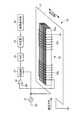
図1に示すように、本実施形態における金属検出機1は、異物である金属の検出処理を行う金属検出処理装置10と、搬送手段としてのコンベア40と、を備え、被検査物5中の金属6の有無を検出するものである。 As shown in FIG. 1, the metal detector 1 in the present embodiment includes a metal
金属検出処理装置10は、金属検出部20と、金属検出回路30と、を備えている。コンベア40は、図示した搬送方向に被検査物5を搬送する搬送手段としての無端環状のコンベアベルト41と、搬送ローラ42及び43と、を備えている。コンベアベルト41は、被検査物5を載置し搬送方向に搬送する搬送面41aを有する。 The metal
図1(a)、(b)に示すように、コンベアベルト41の近傍の、搬送面41aに対してほぼ平行な位置に、金属検出部20が配置されている。金属検出部20は、金属検出回路30に接続されている。 As shown in FIGS. 1A and 1B, the
金属検出回路30は、図2に示すように、発振器31、増幅手段としての差動増幅器32(32a〜32d)、検波部33(33a〜33d)、ADC(アナログデジタル変換器)34(34a〜34d)、判定手段としての判定部35(35a〜35d)、結果表示部36を備えている。 As shown in FIG. 2, the
金属検出部20は、磁界を発生する励磁コイル21と、この励磁コイル21の面とほぼ平行な方向、かつ、搬送方向にほぼ直交する方向(「搬送面41aの幅方向」という場合がある)に4列に並んだ検出コイル22と、を備えている。なお、本実施形態では、検出コイル22を4列とした例を挙げるが、本発明はこれに限定されず、例えば1列であってもよい。また、図面では、搬送面41aの幅方向を単に「幅方向」と記載して示している。 The
励磁コイル21は、矩形状の形状を有し、搬送面41a(図1参照)の近傍の、搬送面41aとほぼ平行な平面内に環状に巻かれている。励磁コイル21の巻き数は、例えば1〜5ターン程度である。この励磁コイル21は、発振器31に接続され、被検査物5が通過する領域に磁界を発生するようになっている。なお、励磁コイル21の形状は矩形状に限定されず、円形状、楕円形状等であってもよい。 The
図3に示すように、検出コイル22は、細長い矩形平板状の複数の磁気コア22aと、この磁気コア22aに巻かれた一対のコイル22b及び22cと、を備えている。 As shown in FIG. 3, the
磁気コア22aは、扁平形状の磁性体、例えばアモルファス磁性体で形成され、長手方向が搬送方向に沿うよう配置されている。また、磁気コア22aは、搬送面41aの幅方向に板厚方向を有し、その板厚方向に複数積層されている。なお、磁気コア22aは、1枚の構成であってもよい。 The
コイル22b及び22cは、それぞれ、積層された磁気コア22aに、互いに逆方向に巻かれて直列に接続されており、一対の逆直列接続コイルの構成を有する。コイル22bの一端は差動増幅器32(図2参照)の一方の入力端子に接続されている。コイル22bの他端は、コイル22cの一端に接続されている。コイル22cの他端はグランドに接続されている。 Each of the
図2に戻り、発振器31は、例えば、周波数が数kHz〜10MHzの発振信号を生成し、金属検出部20の励磁コイル21及び検波部33に出力するようになっている。 Returning to FIG. 2, the
差動増幅器32は、差動増幅器32a〜32dで構成され、それぞれが2つの入力端子及び1つの出力端子を有する。 The
差動増幅器32a〜32dは、それぞれ、一方の入力端子がコイル22bの一端に接続され、他方の入力端子がグランドを介してコイル22cの他端に接続され、対をなす2つのコイル22b及び22cからの信号電圧の差をとって増幅するようになっている。 In each of the
検波部33は、検波部33a〜33dで構成されている。検波部33a〜33dは、それぞれ、発振器31と、差動増幅器32a〜32dの出力端子とに接続され、発振器31の出力に同期させて差動増幅器32a〜32dの各出力信号を同期検波するようになっている。 The
ADC34は、ADC34a〜34dで構成されている。ADC34a〜34dは、それぞれ、検波部33a〜33dの出力信号を、アナログ信号からデジタル信号に変換するようになっている。 The
判定部35は、判定部35a〜35dで構成されている。判定部35a〜35dは、それぞれ、ADC34a〜34dの出力端子に接続され、これらの出力信号に基づいて、予め設定された判定用閾値を参照して被検査物5中の金属6の有無を判定するようになっている。 The
結果表示部36は、判定部35a〜35dによる金属6の有無の判定結果を例えば液晶画面に表示するようになっている。 The
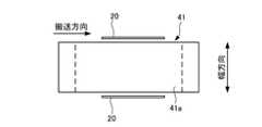
次に、金属検出部20の金属検出の原理について、図4を用いて説明する。図4(a)は、金属検出部20の平面図である。図4(b)は、図4(a)における搬送方向の断面図である。図4(c)は、被検査物5が金属6を含む場合の搬送方向の断面図である。なお、説明を簡単にするため、励磁コイル21の内側に1つの磁気コア22aを有する1つの検出コイル22があるものとする。 Next, the principle of metal detection of the
図4(a)、(b)に示すように、検出コイル22は、励磁コイル21の内側に、搬送面41aの幅方向に板厚方向を有する磁気コア22aの長手方向が搬送方向に沿って配置されている。また、コイル22b及び22cは、互いに逆方向に巻かれて直列に接続されている。 As shown in FIGS. 4A and 4B, the longitudinal direction of the
すなわち、励磁コイル21が発生する磁界の方向と、検出コイル22の感度軸とが直交している。検出コイル22は、励磁コイル21に交流電流を流しても誘起電圧を生じないよう配置位置が調整されている。通常、検出コイル22は、励磁コイル21の左側のコイル21aと右側のコイル21bとの間の中央に配置すれば誘起電圧が生じない。ここで、誘起電圧が生じないとは、誘起電圧がゼロボルトであることのみを意味するものではなく、金属6を検出できる程度に誘起電圧が低い状態にあることをいう。 That is, the direction of the magnetic field generated by the
また、金属検出機1は、上記の配置に加え、検出コイル22を差動構成に接続しているため、高い平衡性が実現でき、高感度の検出を可能としている。 Further, in addition to the above arrangement, the metal detector 1 has a
さらに、金属検出機1は、磁気コア22aの板厚方向を搬送面41aの幅方向としているので、励磁コイル21が発生する磁束の通過可能な断面積が極めて狭くなって、磁気コア22aに渦電流が発生し難い構造である。その結果、磁気コア22aの板厚方向が搬送面41aと直交するものと比べ、金属検出機1は、(1)励磁コイル21のパワーが渦電流により消費され難くなるので、低消費電力を図ることができ、(2)磁気コア22aに渦電流が発生し難くなるので、検出コイル22の出力信号のバランスがとり易くなり、出力信号の安定化を図ることができる。 Furthermore, since the metal detector 1 uses the thickness direction of the
さらに、金属検出機1は、磁気コア22aをその板厚方向に積層することにより、磁性体の体積を増やすことができるので、金属の検出感度をより向上させることができる。 Furthermore, since the metal detector 1 can increase the volume of the magnetic material by laminating the
なお、コイル22bとコイル22cとの間や、検出コイル22から外部への接続部で用いるコイル線は、磁界の影響を避けるため、ツイストペア線にするのが好ましい。 The coil wire used between the
図4(c)に示すように、金属検出部20の上部を金属6が通過すると、励磁コイル21が発生した磁界によって金属6中に新たな磁界が発生する。この場合、金属6が導体か磁性体かによりメカニズムが異なる。磁性体の場合は、金属6が磁化し新たな磁界を発生し、導体の場合は金属6に渦電流が発生し新たな磁界を発生する。コイル22bとコイル22cの中央付近を金属6が通過するとき、図4(c)に示す状態では、新たに発生した磁界は、コイル22bには搬送方向の逆方向に、コイル22cには搬送方向に流れる。その結果、新たな磁界によって発生した誘起電圧が検出コイル22に発生し、検出コイル22の誘起電圧が差動増幅器32によって加算され、検波部33において同期検波されることによってスパイク状の電圧信号(図2参照)が生じることとなる。 As shown in FIG. 4C, when the metal 6 passes through the upper part of the
次に、検出コイル22の変形例について図5を用いて説明する。前述の説明では、検出コイル22が、1つの磁気コア22aにコイル22b及び22cが巻かれた構成を有していた。本発明は、これに限定されず、複数の磁気コアを搬送方向に並べて配置した構成とすることもできる。以下、2つの磁気コアを搬送方向に並べた例を挙げて説明する。 Next, a modification of the
図5(a)は、検出コイル23及び24がほぼ搬送方向に沿って1列に配置された例を示している。検出コイル23及び24は、それぞれ、磁気コア23a及び24aを有している。磁気コア23a及び24aは、個別に巻かれたコイル23b及び24bを有している。コイル23b及び24bは、互いに逆方向に巻かれて直列に接続されている。図5(b)は、検出コイル23及び24がほぼ搬送方向に沿って配置され、検出コイル24が搬送方向に対して所定角度で傾いて配置された構成を示している。図5(c)は、検出コイル23及び24がともに搬送方向に対してほぼ同じ角度で傾いて1列になるよう配置された構成を示している。図5(d)は、検出コイル23及び24が、搬送方向に対して互いに異なる角度で傾いて配置された構成を示している。 FIG. 5A shows an example in which the detection coils 23 and 24 are arranged in a line substantially along the transport direction. The detection coils 23 and 24 have
次に、本実施形態における金属検出機1の動作について図1及び図2を用いて説明する。 Next, operation | movement of the metal detector 1 in this embodiment is demonstrated using FIG.1 and FIG.2.
発振器31は、例えば100kHzの周波数の発振信号を生成し、金属検出部20の励磁コイル21及び検波部33に出力する。その結果、励磁コイル21は、被検査物5が通過する領域に磁界を発生する。 The
励磁コイル21が磁界を発生している状態で、金属6を含む被検査物5が検出コイル22の上部近傍を通過すると、金属6により新たな磁界が発生する。この新たな磁界によって発生した誘起電圧が検出コイル22に発生する。 When the
差動増幅器32は、対をなす2つのコイル22b及び22cが発生した各誘起電圧を加算して増幅し、検波部33に出力する。 The
検波部33は、発振器31からの発信信号に基づいて、差動増幅器32が増幅した信号を同期検波することによってスパイク状の電圧信号をADC34に出力する。 The
ADC34は、検波部33からの電圧信号をアナログ値からデジタル値の信号に変換して判定部35に出力する。 The
判定部35は、ADC34の出力信号と、予め設定された判定用閾値とに基づいて被検査物5中の金属6の有無を判定し、その判定結果のデータを結果表示部36に出力する。 The
結果表示部36は、判定部35による判定結果を例えば液晶画面に表示する。ここで、結果表示部36は、検出コイル22ごとに判定結果を表示する構成を有し、被検査物5中の金属6が検出された位置を識別表示するのが好ましい。 The
以上のように、本実施形態における金属検出機1は、長手方向が搬送方向に沿うよう配置され、励磁コイル21の面とほぼ平行な方向、かつ、搬送方向にほぼ直交する方向に板厚方向を有する矩形平板状の磁気コア22aと、磁気コア22aに互いに逆方向に巻かれ直列に接続された一対のコイル22b及び22cと、を有する検出コイル22を備えるので、一対のコイル22b及び22cの差動出力電圧に基づいて金属6の検出感度をより向上させることができる。 As described above, the metal detector 1 according to the present embodiment is arranged such that the longitudinal direction thereof is along the transport direction, the plate thickness direction in a direction substantially parallel to the surface of the
すなわち、本実施形態における金属検出機1は、従来のように、金属6の検出感度をより向上させるために受信コイルの巻数を増加させる必要がなく、コンベアベルト41の搬送面41aに対して垂直方向の寸法は増大しない。 That is, the metal detector 1 according to the present embodiment does not need to increase the number of turns of the receiving coil in order to further improve the detection sensitivity of the metal 6, and is perpendicular to the
したがって、本実施形態における金属検出機1は、被検査物5中の金属6の検出感度の向上及び省スペース化を図ることができる。 Therefore, the metal detector 1 in the present embodiment can improve the detection sensitivity of the metal 6 in the
次に、本実施形態における金属検出機1の他の態様について3つの例を挙げて説明する。なお、前述の金属検出機1と同様な構成には同一の符号を付し、その説明を省略する。 Next, another aspect of the metal detector 1 in the present embodiment will be described with three examples. In addition, the same code | symbol is attached | subjected to the structure similar to the above-mentioned metal detector 1, and the description is abbreviate | omitted.
[第1の他の態様]
図6は、第1の他の態様における金属検出処理装置を示している。この金属検出処理装置の金属検出部20は、1つの検出コイル25を備えている。検出コイル25は、搬送面41a(図1参照)の幅方向の長さと同等程度にコア22aが複数積層されたものである。積層された磁気コア22aには、コイル22b及び22cが互いに逆方向に巻かれて直列に接続されている。コイル22b及び22cには1つの差動増幅器32が接続されている。この構成により、第1の他の態様における金属検出処理装置は、差動増幅器32から判定部35までをそれぞれ1つずつで構成することができるので、回路構成の簡易化を図ることができる。[First other aspect]
FIG. 6 shows a metal detection processing apparatus according to the first other aspect. The
[第2の他の態様]
図7は、第2の他の態様における金属検出処理装置を示している。この金属検出処理装置は、コンベアベルト41を挟んで互いに対向した上側及び下側の2つの金属検出部20を有している。上側の金属検出部20は、例えば、被検査物5が通過可能なトンネル部の上部に設けられている。この構成により、第2の他の態様における金属検出処理装置は、被検査物5に含まれる金属6を被検査物5の上側及び下側の両方向から検出することができる。[Second other embodiment]
FIG. 7 shows a metal detection processing apparatus according to a second other embodiment. This metal detection processing apparatus has two
[第3の他の態様]
図8は、第3の他の態様における金属検出処理装置を示している。この金属検出処理装置は、搬送方向と直交する方向に互いに対向し、コンベアベルト41の近傍に設けられた2つの金属検出部20を有している。すなわち、2つの金属検出部20は、それぞれ、搬送面41aとほぼ垂直な平面に配置されている。この構成により、第3の他の態様における金属検出処理装置は、被検査物5に含まれる金属6を搬送方向と直交する、搬送面41aの幅方向の両方向から検出することができる。なお、搬送面41aとほぼ垂直な平面に、1つの金属検出部20を配置する構成であってもよい。[Third Other Mode]
FIG. 8 shows a metal detection processing apparatus according to a third other aspect. This metal detection processing apparatus has two
(第2実施形態)
本実施形態における金属検出機の構成について図9を用いて説明する。(Second Embodiment)
The structure of the metal detector in this embodiment is demonstrated using FIG.
図9に示すように、本実施形態における金属検出機は、第1実施形態における金属検出処理装置10(図2参照)に代えて金属検出処理装置50を備えた点が異なっている。したがって、第1実施形態と重複する構成の説明は省略する。 As shown in FIG. 9, the metal detector in the present embodiment is different in that a metal
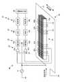
金属検出処理装置50は、金属検出部60、金属検出回路70を備えている。金属検出部60は、励磁コイル21、検出コイル61を備えている。金属検出回路70は、発振器31、増幅手段としての差動増幅器32(32a〜32b)、検波部33(33a〜33b)、ADC34(34a〜34b)、判定手段としての判定部35(35a〜35b)、結果表示部36を備えている。 The metal
検出コイル61は、搬送方向とほぼ一致する方向に配置されている。なお、本実施形態では、搬送方向とほぼ直交する方向に1つの検出コイル61を配置した例を挙げているが、本発明はこれに限定されず、複数の検出部を配置する構成としてもよい。 The
検出コイル61は、第1実施形態における第1の他の態様(図6参照)と同様に積層されたコア22aと、積層された磁気コア22aに巻かれた二対のコイル62a及び62b、コイル63a及び63bと、を有する。 The
一方の一対のコイルであるコイル62a及び62bにおいて、コイル62aの一端は差動増幅器32bの一方の入力端子に接続され、コイル62aの他端はコイル62bの一端に接続され、コイル62bの他端はグランドを介して差動増幅器32bの他方の入力端子に接続されている。 In the
他方の一対のコイルであるコイル63a及び63bにおいて、コイル63aの一端は差動増幅器32aの一方の入力端子に接続され、コイル63aの他端はコイル63bの一端に接続され、コイル63bの他端はグランドを介して差動増幅器32aの他方の入力端子に接続されている。 In the
本実施形態では、検出コイル61が二対のコイル62a及び62b、コイル63a及び63bを有し、一方の一対のコイル62aと62bとのコイル間隔と、他方の一対のコイル63aと63bとのコイル間隔とが互いに異なっている。すなわち、一方の一対のコイル62a及び62bのコイル間隔は、他方の一対のコイル63a及び63bのコイル間隔よりも広い。 In the present embodiment, the
この構成により、本実施形態における金属検出処理装置50は、互いに異なるコイル間隔の二対のコイル62a及び62bとコイル63a及び63bとにより、より広範な感度領域に感度を有することとなる。具体的には、金属検出処理装置50は、一方の一対のコイル62a及び62bにより比較的遠方での金属検出感度を有し、他方の一対のコイル63a及び63bにより比較的近辺での金属検出感度を有する。 With this configuration, the metal
したがって、本実施形態における金属検出機は、被検査物5中の金属6の検出感度の向上及び省スペース化を図ることができるとともに、低コスト化を図ることもでき、さらに、より広範な感度領域に感度を有する。 Therefore, the metal detector in the present embodiment can improve the detection sensitivity of the metal 6 in the
なお、第2実施形態では、二対のコイルを例に挙げて説明したが、本発明はこれに限定されるものではなく、三対以上のコイルを磁気コア22aに設けた構成であってもよい。この構成を備えた金属検出機は、二対のコイルを用いたものよりも、より広範な感度領域に感度を有することとなる。 In the second embodiment, two pairs of coils have been described as examples. However, the present invention is not limited to this, and a configuration in which three or more pairs of coils are provided in the
以上のように、本発明に係る金属検出機は、金属の検出感度の向上及び省スペース化を図ることができるという効果を有し、食品や衣類等の被検査物中の金属の有無を検出する金属検出機として有用である。 As described above, the metal detector according to the present invention has the effect of improving the metal detection sensitivity and saving space, and detects the presence or absence of metal in the inspected object such as food or clothing. It is useful as a metal detector.
1 金属検出機
5 被検査物
6 金属
10、50 金属検出処理装置
20、60 金属検出部
21 励磁コイル
22、23、24、25、61 検出コイル
22a、23a、24a 磁気コア
22b、22c、23b、24b、62a、62b、63a、63b コイル
30、70 金属検出回路
31 発振器
32(32a〜32d) 差動増幅器(増幅手段)
35(35a〜35d) 判定部(判定手段)
41 コンベアベルト(搬送手段)
41a 搬送面DESCRIPTION OF SYMBOLS 1
35 (35a-35d) determination part (determination means)
41 Conveyor belt (conveying means)
41a Conveying surface
Claims (5)
Translated fromJapanese前記被検査物を所定の搬送方向に搬送する搬送面(41a)を有する搬送手段(41)と、
前記搬送面に対して平行な平面及び垂直な平面のいずれか一方の平面内に環状に巻かれ前記磁界を発生する励磁コイル(21)と、
前記励磁コイルの内側に設けられ前記金属を検出する検出コイル(22、25、26)と、
を備え、
前記検出コイルは、
長手方向が前記搬送方向に沿うよう配置され、前記励磁コイルの面と平行な方向、かつ、前記搬送方向に直交する方向に板厚方向を有する矩形平板状の1つの磁気コア(22a)と、
前記磁気コアに互いに逆方向に巻かれ直列に接続された少なくとも一対のコイル(22b及び22c、62a及び62b、63a及び63b)と、
を備えたことを特徴とする金属検出機。A metal detector for passing the object to be inspected (5) through a magnetic field and detecting the presence or absence of the metal (6) in the object to be inspected,
A transport means (41) having a transport surface (41a) for transporting the inspection object in a predetermined transport direction;
An exciting coil (21) that is annularly wound in one of a plane parallel to the transport surface and a plane perpendicular to the transport surface to generate the magnetic field;
A detection coil (22, 25, 26 ) provided inside the excitation coil for detecting the metal;
With
The detection coil is
Longitudinal direction is arranged along the conveying direction, the plane parallel to the direction of the exciting coil, and a rectangular plate-likesingle magnetic core having a thickness in the direction perpendicular to the conveying direction (22a) ,
At least a pair of coils (22b and 22c, 62a and 62b, 63a and 63b) wound in opposite directions around the magnetic core and connected in series;
A metal detector characterized by comprising:
前記増幅手段が増幅した電圧に基づいて前記被検査物中の金属の有無を判定する判定手段(35a〜35d)と、
をさらに備えたことを特徴とする請求項1から請求項4までのいずれか1項に記載の金属検出機。Amplifying means (32a to 32d) connected to each of the pair of coils, respectively, for amplifying the voltage at both ends of the pair of coils;
Determination means (35a to 35d) for determining the presence or absence of metal in the inspection object based on the voltage amplified by the amplification means;
The metal detector according to any one of claims 1 to4 , further comprising:
Priority Applications (1)
| Application Number | Priority Date | Filing Date | Title |
|---|---|---|---|
| JP2015104800AJP6590526B2 (en) | 2015-05-22 | 2015-05-22 | Metal detector |
Applications Claiming Priority (1)
| Application Number | Priority Date | Filing Date | Title |
|---|---|---|---|
| JP2015104800AJP6590526B2 (en) | 2015-05-22 | 2015-05-22 | Metal detector |
Publications (2)
| Publication Number | Publication Date |
|---|---|
| JP2016217947A JP2016217947A (en) | 2016-12-22 |
| JP6590526B2true JP6590526B2 (en) | 2019-10-16 |
Family
ID=57580903
Family Applications (1)
| Application Number | Title | Priority Date | Filing Date |
|---|---|---|---|
| JP2015104800AActiveJP6590526B2 (en) | 2015-05-22 | 2015-05-22 | Metal detector |
Country Status (1)
| Country | Link |
|---|---|
| JP (1) | JP6590526B2 (en) |
Families Citing this family (6)
| Publication number | Priority date | Publication date | Assignee | Title |
|---|---|---|---|---|
| JP6808900B2 (en)* | 2017-02-27 | 2021-01-06 | アンリツインフィビス株式会社 | Metal detector |
| JP6790323B2 (en)* | 2017-02-27 | 2020-11-25 | アンリツインフィビス株式会社 | Metal detector |
| JP6924793B2 (en)* | 2019-03-20 | 2021-08-25 | アンリツ株式会社 | Metal detector |
| JP7256529B2 (en)* | 2019-05-30 | 2023-04-12 | 笹田磁気計測研究所株式会社 | Gradient magnetic field sensor |
| JP6940910B1 (en)* | 2021-07-01 | 2021-09-29 | 株式会社沖縄計測 | Magnetic Tomography System and Magnetic Tomography Method |
| JP6940911B1 (en)* | 2021-07-01 | 2021-09-29 | 株式会社沖縄計測 | Magnetic Tomography System and Magnetic Tomography Method |
Family Cites Families (10)
| Publication number | Priority date | Publication date | Assignee | Title |
|---|---|---|---|---|
| JPS6267484A (en)* | 1985-09-20 | 1987-03-27 | Asano Yukihiko | Method and apparatus for selectively detecting metal |
| JPH0619469B2 (en)* | 1988-04-13 | 1994-03-16 | 大和製衡株式会社 | Foreign matter contamination detector such as metal |
| JP2893287B2 (en)* | 1990-05-25 | 1999-05-17 | アンリツ株式会社 | Article inspection equipment |
| JP3041026B2 (en)* | 1990-09-07 | 2000-05-15 | アンリツ株式会社 | Metal detector |
| JP2912063B2 (en)* | 1991-10-02 | 1999-06-28 | 偕成エンジニア株式会社 | Detection coil |
| JP4138179B2 (en)* | 1999-09-24 | 2008-08-20 | アンリツ産機システム株式会社 | Metal detector |
| JP4227038B2 (en)* | 2004-02-27 | 2009-02-18 | 株式会社東芝 | Magnetic detection device |
| JP2006086385A (en)* | 2004-09-17 | 2006-03-30 | Hitachi Ferrite Electronics Ltd | Coil component |
| EP3196903B1 (en)* | 2011-01-19 | 2019-05-08 | Technova Inc. | Contactless power transfer apparatus |
| WO2015049766A1 (en)* | 2013-10-03 | 2015-04-09 | 株式会社システムスクエア | Metal-detection device |
- 2015
- 2015-05-22JPJP2015104800Apatent/JP6590526B2/enactiveActive
Also Published As
| Publication number | Publication date |
|---|---|
| JP2016217947A (en) | 2016-12-22 |
Similar Documents
| Publication | Publication Date | Title |
|---|---|---|
| JP6590526B2 (en) | Metal detector | |
| JP4835960B2 (en) | Mobile system | |
| JP6294112B2 (en) | Metal detector | |
| JP6121689B2 (en) | Metal detector | |
| JP6590525B2 (en) | Metal detector | |
| JP6159112B2 (en) | Metal detector | |
| JP2011196773A (en) | Metal detector | |
| CN111670388B (en) | Inspection apparatus | |
| JP2014228522A (en) | Metal detection machine | |
| KR101786794B1 (en) | Metal detection sensor and metal detector including the same | |
| JP6808900B2 (en) | Metal detector | |
| JP6790323B2 (en) | Metal detector | |
| JP5069162B2 (en) | Metal detector | |
| JP6103848B2 (en) | Foreign object detection device | |
| JP6924793B2 (en) | Metal detector | |
| JP2008232745A (en) | Iron piece detector | |
| JP2006058113A (en) | Metal detector | |
| CN216561039U (en) | Metal detecting device | |
| KR20170029350A (en) | Metal detection sensor and metal detector including the same | |
| JP2005214789A (en) | Metal detection device | |
| JP2016133483A (en) | Metal detector | |
| JPH08101279A (en) | Metal detector | |
| JP2023124388A (en) | magnetic sensor | |
| JPH0821880A (en) | Magnetic substance detector | |
| JP5695429B2 (en) | Metal detector |
Legal Events
| Date | Code | Title | Description |
|---|---|---|---|
| A621 | Written request for application examination | Free format text:JAPANESE INTERMEDIATE CODE: A621 Effective date:20180328 | |
| A977 | Report on retrieval | Free format text:JAPANESE INTERMEDIATE CODE: A971007 Effective date:20190125 | |
| A131 | Notification of reasons for refusal | Free format text:JAPANESE INTERMEDIATE CODE: A131 Effective date:20190219 | |
| A521 | Request for written amendment filed | Free format text:JAPANESE INTERMEDIATE CODE: A523 Effective date:20190326 | |
| TRDD | Decision of grant or rejection written | ||
| A01 | Written decision to grant a patent or to grant a registration (utility model) | Free format text:JAPANESE INTERMEDIATE CODE: A01 Effective date:20190903 | |
| A61 | First payment of annual fees (during grant procedure) | Free format text:JAPANESE INTERMEDIATE CODE: A61 Effective date:20190917 | |
| R150 | Certificate of patent or registration of utility model | Ref document number:6590526 Country of ref document:JP Free format text:JAPANESE INTERMEDIATE CODE: R150 | |
| S111 | Request for change of ownership or part of ownership | Free format text:JAPANESE INTERMEDIATE CODE: R313115 | |
| R350 | Written notification of registration of transfer | Free format text:JAPANESE INTERMEDIATE CODE: R350 | |
| R250 | Receipt of annual fees | Free format text:JAPANESE INTERMEDIATE CODE: R250 | |
| R250 | Receipt of annual fees | Free format text:JAPANESE INTERMEDIATE CODE: R250 | |
| R250 | Receipt of annual fees | Free format text:JAPANESE INTERMEDIATE CODE: R250 | |
| R250 | Receipt of annual fees | Free format text:JAPANESE INTERMEDIATE CODE: R250 |