JP6588908B2 - Sample analysis substrate, sample analysis apparatus, sample analysis system, and program for sample analysis system - Google Patents
Sample analysis substrate, sample analysis apparatus, sample analysis system, and program for sample analysis systemDownload PDFInfo
- Publication number
- JP6588908B2 JP6588908B2JP2016531362AJP2016531362AJP6588908B2JP 6588908 B2JP6588908 B2JP 6588908B2JP 2016531362 AJP2016531362 AJP 2016531362AJP 2016531362 AJP2016531362 AJP 2016531362AJP 6588908 B2JP6588908 B2JP 6588908B2
- Authority
- JP
- Japan
- Prior art keywords
- chamber
- liquid
- substrate
- sample analysis
- flow path
- Prior art date
- Legal status (The legal status is an assumption and is not a legal conclusion. Google has not performed a legal analysis and makes no representation as to the accuracy of the status listed.)
- Active
Links
Images


Classifications
- G—PHYSICS
- G01—MEASURING; TESTING
- G01N—INVESTIGATING OR ANALYSING MATERIALS BY DETERMINING THEIR CHEMICAL OR PHYSICAL PROPERTIES
- G01N35/00—Automatic analysis not limited to methods or materials provided for in any single one of groups G01N1/00 - G01N33/00; Handling materials therefor
- G01N35/00029—Automatic analysis not limited to methods or materials provided for in any single one of groups G01N1/00 - G01N33/00; Handling materials therefor provided with flat sample substrates, e.g. slides
- G01N35/00069—Automatic analysis not limited to methods or materials provided for in any single one of groups G01N1/00 - G01N33/00; Handling materials therefor provided with flat sample substrates, e.g. slides whereby the sample substrate is of the bio-disk type, i.e. having the format of an optical disk
- G—PHYSICS
- G01—MEASURING; TESTING
- G01N—INVESTIGATING OR ANALYSING MATERIALS BY DETERMINING THEIR CHEMICAL OR PHYSICAL PROPERTIES
- G01N33/00—Investigating or analysing materials by specific methods not covered by groups G01N1/00 - G01N31/00
- G01N33/48—Biological material, e.g. blood, urine; Haemocytometers
- G01N33/483—Physical analysis of biological material
- G01N33/487—Physical analysis of biological material of liquid biological material
- G—PHYSICS
- G01—MEASURING; TESTING
- G01N—INVESTIGATING OR ANALYSING MATERIALS BY DETERMINING THEIR CHEMICAL OR PHYSICAL PROPERTIES
- G01N33/00—Investigating or analysing materials by specific methods not covered by groups G01N1/00 - G01N31/00
- G01N33/48—Biological material, e.g. blood, urine; Haemocytometers
- G01N33/50—Chemical analysis of biological material, e.g. blood, urine; Testing involving biospecific ligand binding methods; Immunological testing
- G01N33/53—Immunoassay; Biospecific binding assay; Materials therefor
- G01N33/5302—Apparatus specially adapted for immunological test procedures
- G—PHYSICS
- G01—MEASURING; TESTING
- G01N—INVESTIGATING OR ANALYSING MATERIALS BY DETERMINING THEIR CHEMICAL OR PHYSICAL PROPERTIES
- G01N35/00—Automatic analysis not limited to methods or materials provided for in any single one of groups G01N1/00 - G01N33/00; Handling materials therefor
- G01N35/00584—Control arrangements for automatic analysers
- G—PHYSICS
- G01—MEASURING; TESTING
- G01N—INVESTIGATING OR ANALYSING MATERIALS BY DETERMINING THEIR CHEMICAL OR PHYSICAL PROPERTIES
- G01N35/00—Automatic analysis not limited to methods or materials provided for in any single one of groups G01N1/00 - G01N33/00; Handling materials therefor
- G01N2035/00465—Separating and mixing arrangements
- G01N2035/00495—Centrifuges
Landscapes
- Health & Medical Sciences (AREA)
- Life Sciences & Earth Sciences (AREA)
- Engineering & Computer Science (AREA)
- Immunology (AREA)
- Chemical & Material Sciences (AREA)
- Biomedical Technology (AREA)
- Physics & Mathematics (AREA)
- Pathology (AREA)
- General Physics & Mathematics (AREA)
- General Health & Medical Sciences (AREA)
- Biochemistry (AREA)
- Analytical Chemistry (AREA)
- Urology & Nephrology (AREA)
- Molecular Biology (AREA)
- Hematology (AREA)
- Medicinal Chemistry (AREA)
- Food Science & Technology (AREA)
- Microbiology (AREA)
- Cell Biology (AREA)
- Biotechnology (AREA)
- Biophysics (AREA)
- Automatic Analysis And Handling Materials Therefor (AREA)
Description
Translated fromJapanese本願は、試料分析用基板、試料分析装置、試料分析システムおよび試料分析システム用プログラムに関する。 The present application relates to a sample analysis substrate, a sample analysis apparatus, a sample analysis system, and a sample analysis system program.
従来、尿や血液等の検体中の特定成分を分析するために試料分析用基板を用いる技術が知られている。例えば、特許文献1は、流路・チャンバー等が形成された円盤状の試料分析用基板を用い、試料分析用基板を回転等させることで、溶液の移送、分配、混合、検体溶液中の成分の分析等を行う技術を開示している。 Conventionally, a technique using a sample analysis substrate for analyzing a specific component in a specimen such as urine or blood is known. For example, Patent Document 1 uses a disk-shaped sample analysis substrate on which a channel, a chamber, and the like are formed, and rotates the sample analysis substrate to transfer, distribute, and mix the components in the sample solution. The technology which performs analysis etc. of this is disclosed.
検体中の特定成分の分析には、酵素反応、免疫反応等を用い、複雑な反応ステップを介する分析法がある。このような複雑な反応ステップを介する分析法を試料分析用基板中で行うことができる技術が求められていた。 Analysis of a specific component in a specimen includes an analysis method using complicated reaction steps using an enzyme reaction, an immune reaction, or the like. There has been a demand for a technique capable of performing an analysis method through such a complicated reaction step in a sample analysis substrate.
本願の限定的ではない例示的な実施形態は、より複雑な反応ステップを介して検体中の成分の分析が行われる分析法に対応できる試料分析用基板、試料分析装置、試料分析システムおよび試料分析システム用プログラムを提供する。 Non-limiting exemplary embodiments of the present application provide a sample analysis substrate, a sample analysis apparatus, a sample analysis system, and a sample analysis that can be applied to an analysis method in which components in a specimen are analyzed through more complicated reaction steps. Provide system programs.
本願の一態様に係る試料分析用基板は、回転運動によって液体の移送を行う試料分析用基板であって、回転軸を有する基板と、前記基板内に位置し、液体を保持するための第1空間を有する第1チャンバーと、前記基板内において、前記第1チャンバーから排出される前記液体を保持するための第2空間を有する第2チャンバーと、前記基板内に位置しており、前記第1チャンバーおよび前記第2チャンバーを接続する経路を有し、毛細管現象により前記第1空間内に保持された液体で満たすことが可能な第1流路とを備え、前記第1チャンバーの第1空間は、第1部分および第2部分と、前記第1部分および前記第2部分の間に位置しており前記第1部分および前記第2部分を連結する連結部分とを有し、前記基板は、第1空間の前記第1部分および前記第2部分を区切る壁部分を有し、前記第2チャンバーは前記第1チャンバーの第1部分よりも回転軸から遠くに位置し、前記第1空間の前記連結部分は、前記基板の前記壁部分よりも前記回転軸側に位置し、前記第1空間の前記第2部分は少なくとも前記第1部分よりも前記回転軸から遠くに位置する部分を含む。 A sample analysis substrate according to an aspect of the present application is a sample analysis substrate that transfers a liquid by a rotational motion, and includes a substrate having a rotation axis, and a first for holding a liquid that is located in the substrate. A first chamber having a space; a second chamber having a second space for holding the liquid discharged from the first chamber in the substrate; and the first chamber. A first channel having a path connecting the chamber and the second chamber and capable of being filled with a liquid held in the first space by capillary action, wherein the first space of the first chamber is A first portion and a second portion; and a connecting portion that is located between the first portion and the second portion and connects the first portion and the second portion; The first of one space And a wall portion separating the second portion, the second chamber being located farther from the rotation axis than the first portion of the first chamber, and the connecting portion of the first space being The second portion of the first space includes at least a portion located farther from the rotation axis than the first portion.
本願の一態様に係る試料分析用基板、試料分析装置、試料分析システムおよび試料分析システム用プログラムによれば、複雑な反応ステップを介して検体中の成分の分析が行われる分析法に対応できる。 According to the sample analysis substrate, the sample analysis apparatus, the sample analysis system, and the sample analysis system program according to one aspect of the present application, it is possible to cope with an analysis method in which components in a specimen are analyzed through complicated reaction steps.
尿や血液等の検体の成分の分析法には、分析対象物であるアナライトと、アナライトと特異的に結合するリガンドとの結合反応が用いられる場合がある。このような分析法には、例えば、免疫測定法や遺伝子診断法が挙げられる。 As a method for analyzing a component of a specimen such as urine or blood, a binding reaction between an analyte as an analysis target and a ligand that specifically binds to the analyte may be used. Examples of such analysis methods include immunoassay methods and genetic diagnosis methods.
免疫測定法の一例として、競合法および非競合法(サンドイッチイムノアッセイ法)が挙げられる。また、遺伝子診断法の一例として、ハイブリダイゼーションによる遺伝子検出法が挙げられる。これら免疫測定法や遺伝子検出法は、例えば、磁性粒子(「磁性ビーズ」、「磁気粒子」または「磁気ビーズ」等と称することもある。)が用いられる。これら分析法の一例として、磁性粒子を用いたサンドイッチイムノアッセイ法で具体的に説明する。 Examples of immunoassay methods include competitive methods and non-competitive methods (sandwich immunoassay methods). An example of a gene diagnosis method is a gene detection method by hybridization. In these immunoassay methods and gene detection methods, for example, magnetic particles (sometimes referred to as “magnetic beads”, “magnetic particles” or “magnetic beads”) are used. As an example of these analysis methods, a sandwich immunoassay method using magnetic particles will be specifically described.
図1に示すように、まず、磁性粒子302の表面に固定化された一次抗体304(以下、「磁性粒子固定化抗体305」と称する。)と測定対象物である抗原306とを抗原抗体反応とにより結合させる。次に標識物質307が結合された2次抗体(以下、「標識抗体308」と称する。)と抗原306とを抗原抗体反応により結合させる。これにより、抗原306に対して磁性粒子固定化抗体305及び標識抗体308が結合した複合体310が得られる。 As shown in FIG. 1, first, an antigen-antibody reaction between a
この複合体310に結合した標識抗体308の標識物質307に基づくシグナルを検出し、検出したシグナルの量に応じて抗原濃度を測定する。標識物質307には、例えば、酵素(例えば、ペルオキシダーゼ、アルカリフォスファターゼ、ルシフェラーゼ等がある。)、化学発光物質、電気化学発光物質、蛍光物質等が挙げられ、それぞれの標識物質307に応じた色素、発光、蛍光等のシグナルを検出する。 A signal based on the labeling
この一連の反応において、反応物である複合体310を得る上で、検体中の未反応物、磁性粒子等に非特異的に吸着した物質、複合体310の形成に関与しなかった標識抗体308等である未反応物とを分離する必要がある。この分離をB/F分離(Bound/Free Separation)と呼ぶ。競合法による免疫測定法やハイブリダイゼーションによる遺伝子検出法においても、同様に、B/F分離の工程が必要である。磁性粒子を用いない場合は、例えば、ポリスチレンやポリカーボネートといった素材で構成された固相に対し、物理吸着により固定化されたリガンド)、化学結合により固相に固定化されたリガンド、金等で構成された金属基板表面へ固定化(たとえば、自己組織化単分子膜(SAM:self−Assembled Monolayer)を用いた固定化)されたリガンドを用いる場合等が挙げられる。 In this series of reactions, in order to obtain the
B/F分離を十分に行うには、洗浄液で複合体310を含む磁性粒子を複数回洗浄することが好ましい。具体的には、まず、複合体310と、未反応の抗原306、標識抗体308等とを含む反応溶液において、磁石によって磁性粒子を含む複合体310を捕捉した状態で、反応溶液のみを除去する。その後、洗浄液を加えて複合体310を洗浄し、洗浄液を除去する。この洗浄を複数回繰り返し行うことによって、未反応物や非特異吸着物質が十分に除去されたB/F分離が達成され得る。 In order to sufficiently perform the B / F separation, it is preferable to wash the magnetic particles containing the
従来、このような複数回洗浄を行う操作は、分析器具を用いて操作者が手動で行ったり、複雑な機構を有する大型の分析機器によって実現されていた。このため、より簡単に複数回洗浄を行う技術が求められていた。 Conventionally, such an operation of performing multiple times of washing has been realized manually by an operator using an analytical instrument or a large analytical instrument having a complicated mechanism. For this reason, there has been a demand for a technique for performing cleaning more than once more easily.
本願発明者らは、特許文献1に開示されるような試料分析用基板を用いて、複数回の洗浄工程を可能にする技術を詳細に検討し、新規な試料分析用基板、試料分析装置、試料分析システムおよび試料分析システム用プログラムを想到した。本願の一態様に係る試料分析用基板、試料分析装置、試料分析システムおよび試料分析システム用プログラムは、以下の通りである。 The inventors of the present application have studied in detail a technique that enables a plurality of cleaning steps using a sample analysis substrate as disclosed in Patent Document 1, and have developed a novel sample analysis substrate, a sample analysis device, A sample analysis system and a program for the sample analysis system were conceived. A sample analysis substrate, a sample analysis device, a sample analysis system, and a sample analysis system program according to an aspect of the present application are as follows.
[項目1]
回転運動によって液体の移送を行う試料分析用基板であって、
回転軸を有する基板と、
前記基板内に位置し、液体を保持するための第1空間を有する第1チャンバーと、
前記基板内に位置し、前記第1チャンバーから排出される前記液体を保持するための第2空間を有する第2チャンバーと、
前記基板内に位置しており、前記第1チャンバーおよび前記第2チャンバーを接続する経路を有し、毛細管現象により前記第1空間内に保持された液体で満たすことが可能な第1流路と、
を備え、
前記第1チャンバーの第1空間は、第1部分および第2部分と、前記第1部分および前記第2部分の間に位置しており前記第1部分および前記第2部分を連結する連結部分とを有し、
前記基板は、第1空間の前記第1部分および前記第2部分を区切る壁部分を有し、
前記第2チャンバーは前記第1チャンバーの第1部分よりも回転軸から遠くに位置し、
前記第1空間の前記連結部分は、前記基板の前記壁部分よりも前記回転軸側に位置し、
前記第1流路は、前記第1空間の前記第1部分と接続されている、試料分析用基板。
[項目2]
前記回転軸から前記第1部分における前記第1流路の接続位置までの距離は、前記回転軸から前記壁部分の前記回転軸に最も近い点までの距離よりも長い項目1に記載の試料分析用基板。
[項目3]
前記第1空間の前記第1部分は、前記回転軸を中心とし、前記回転軸と前記壁部分の前記回転軸に最も近い点とを結ぶ線分を半径とする円弧よりも外側に位置する部分を含む、項目1または2に記載の試料分析用基板。
[項目4]
前記第1空間の前記第2部分は、前記回転軸を中心とし、前記回転軸と前記壁部分の前記回転軸に最も近い点とを結ぶ線分を半径とする円弧よりも外側に位置する部分を含む、項目1から3のいずれかに記載の試料分析用基板。
[項目5]
前記第1空間の前記第2部分は、前記第1部分よりも前記回転軸から遠くに位置する部分を含む、項目3に記載の試料分析用基板。
[項目6]
前記第1空間の第1部分の、前記回転軸に平行な方向から見て、前記回転軸を中心とし、前記回転軸と前記壁部分の前記回転軸に最も近い点とを結ぶ線分を半径とする円の外側位置する部分の容積は、前記第1空間の1/2以下である項目1から5のいずれかに記載の試料分析用基板。
[項目7]
前記第2空間は、前記第1空間の第1部分の、前記回転軸に平行な方向から見て、前記回転軸を中心とし、前記回転軸と前記壁部分の前記回転軸に最も近い点を結ぶ線分を半径とする円の外側位置する部分の容積よりも大きい項目1から6のいずれかに記載の試料分析用基板。
[項目8]
前記基板内において、前記第2チャンバーよりも前記回転軸から遠くに位置し、前記第2チャンバーから排出される前記液体を保持するための第3空間を有する第3チャンバーと、
前記基板内に位置しており、前記第2チャンバーおよび前記第3チャンバーを接続する経路を有し、毛細管現象により前記第2空間内に保持された液体で満たすことが可能な第2流路と、
をさらに備える項目1から7のいずれかに記載の試料分析用基板。
[項目9]
前記第2流路は、前記回転軸と反対側に凸状の第1屈曲部および前記回転軸側に凸状の第2屈曲部とを含み、前記第1屈曲部は前記第2屈曲部と第2チャンバーとの間に位置し、
前記回転軸から前記第3チャンバーまでの距離は、前記回転軸から前記第1屈曲部の頂点までの距離より長く、
前記回転軸から前記第3チャンバーに保持された液体の、前記基板の回転による遠心力で形成される液面までの距離は、前記回転軸から前記第2屈曲部の頂点までの距離より長い項目8に記載の試料分析用基板。
[項目10]
前記第1流路は、前記回転軸と反対側に凸状の第1屈曲部および前記回転軸側に凸状の第2屈曲部とを含み、前記第1屈曲部は前記第2屈曲部と第1チャンバーとの間に位置し、
前記回転軸から前記第2チャンバーまでの距離は、前記回転軸から前記第1屈曲部の頂点までの距離より長く、
前記回転軸から前記第1チャンバーに保持された液体の、前記基板の回転による遠心力で形成される液面までの距離は、前記回転軸から前記第2屈曲部の頂点までの距離より長い
項目9に記載の試料分析用基板。
[項目11]
前記第2チャンバーに近接して位置する磁石をさらに備える項目1から10のいずれかに記載の試料分析用基板。
[項目12]
項目11に記載の試料分析用基板と、
重力方向に対して0°より大きく90°以下の角度で前記回転軸を傾斜させた状態で、前記試料分析用基板を前記回転軸周りに回転させるモータ、
前記モータの回転軸の角度を検出する回転角度検出回路、
前記回転角度検出回路の検出結果に基づき、前記モータの回転および停止時の角度を制御する駆動回路、および
演算器、メモリおよびメモリに記憶され、前記演算器に実行可能なように構成されたプログラムを含み、前記プログラムに基づき、前記モータ、前記回転角度検出回路、前記原点検出器および前記駆動回路の動作を制御する制御回路
を有する試料分析装置と、
を備えた試料分析システムであって、
前記プログラムは、
前記第1チャンバーに液体が充填された試料分析用基板が前記試料分析装置のターンテーブルに載置された場合において、
(a) 前記試料分析用基板を所定の第1の角度で停止させることにより前記液体の一部を前記第1チャンバー内において重力によって移動させ、前記第1チャンバーの前記第1部分の少なくとも一部を前記液体の一部で満たし、かつ、毛細管現象によって、前記液体の他の一部を前記第1流路に移送させ、
(b) 前記試料分析基板を基板の回転による遠心力で、前記第1流路に満たされた液体にかかる毛細管力よりも強い遠心力が働く速度で回転させることによって、前記第1部分で前記液体の一部を秤量するとともに、過剰な液体を前記第2部分へ移動させることによって残りの液体を前記第2部分に保持し、かつ、秤量した前記第1部分にある前記液体の一部を、前記第1流路を通って前記第2チャンバーへ移動させ、
(c) 前記試料分析用基板を所定の第2の角度で停止させることにより前記残りの液体の一部を前記第1チャンバー内において重力によって移動させ、前記第1チャンバーの前記第1部分の少なくとも一部を前記残りの液体の一部で満たし、かつ、毛細管現象によって、前記残りの液体の他の一部を前記第1流路に移送させ、
(d) 前記試料分析基板を基板の回転による遠心力で、前記第1流路に満たされた液体にかかる毛細管力よりも強い遠心力が働く速度で回転させることによって、前記第1部分で前記残りの液体の一部を秤量するとともに、過剰な液体を前記第2部分へ移動させることによって余剰の液体を前記第2部分に保持し、かつ、秤量した前記第1部分にある前記残りの液体の一部を、前記第1流路を通って前記第2チャンバーへ移動させる、
工程を含む、試料分析システム。
[項目13]
前記工程(b)と工程(c)との間に、
(e) 前記試料分析用基板を、所定の第3の角度で停止させることによって、前記第2チャンバーの液体の一部を毛細管現象によって前記第2流路に移送させ、
(f) 前記試料分析基板を基板の回転による遠心力で、前記第2流路に満たされた液体にかかる毛細管力よりも強い遠心力が働く速度で回転させ、前記第2チャンバーの前記液体を、前記第2流路を通って前記第3チャンバーへ移動させる、
工程をさらに含む、項目12に記載の試料分析システム。
[項目14]
前記工程(d)の後に、
(g) 前記試料分析用基板を、所定の第4の角度で停止させることによって、前記第2チャンバーの液体の一部を毛細管現象によって前記第2流路に移送させ、
(h) 前記試料分析基板を基板の回転による遠心力で、前記第2流路に満たされた液体にかかる毛細管力よりも強い遠心力が働く速度で回転させ、前記第2チャンバーの前記液体を、前記第2流路を通って前記第3チャンバーへ移動させる、
工程をさらに含む、項目13に記載の試料分析システム。
[項目15]
前記工程(a)および(b)の少なくとも一方において、前記試料分析用基板の回転を停止後、前記基板を、時計回りおよび反時計回りに所定の角度で交互に回転させる項目12に記載の試料分析システム。
[項目16]
重力方向に対して0°より大きく90°以下の角度で前記回転軸を傾斜させた状態で、項目8に記載の試料分析用基板を前記回転軸周りに回転させるモータ、
前記モータの回転軸の角度を検出する回転角度検出回路、
前記回転角度検出回路の検出結果に基づき、前記モータの回転および停止時の角度を制御する駆動回路、および
演算器、メモリおよびメモリに記憶され、前記演算器に実行可能なように構成されたプログラムを含み、前記プログラムに基づき、前記モータ、前記回転角度検出回路および前記駆動回路の動作を制御する制御回路
を備え、
前記プログラムは、
前記第1チャンバーに液体が充填された試料分析用基板が前記試料分析装置のターンテーブルに載置された場合において、
(a) 前記試料分析用基板を所定の第1の角度で停止させることにより前記液体の一部を前記第1チャンバー内において重力によって移動させ、前記第1チャンバーの前記第1部分の少なくとも一部を前記液体の一部で満たし、かつ、毛細管現象によって、前記液体の他の一部を前記第1流路に移送させ、
(b) 前記試料分析基板を基板の回転による遠心力で、前記第1流路に満たされた液体にかかる毛細管力よりも強い遠心力が働く速度で回転させることによって、前記第1部分で前記液体の一部を秤量するとともに、過剰な液体を前記第2部分へ移動させることによって残りの液体を前記第2部分に保持し、かつ、秤量した前記第1部分にある前記液体の一部を、前記第1流路を通って前記第2チャンバーへ移動させ、
(c) 前記試料分析用基板を所定の第2の角度で停止させることにより前記残りの液体の一部を前記第1チャンバー内において重力によって移動させ、前記第1チャンバーの前記第1部分の少なくとも一部を前記残りの液体の一部で満たし、かつ、毛細管現象によって、前記残りの液体の他の一部を前記第1流路に移送させ、
(d) 前記試料分析基板を基板の回転による遠心力で、前記第1流路に満たされた液体にかかる毛細管力よりも強い遠心力が働く速度で回転させることによって、前記第1部分で前記残りの液体の一部を秤量するとともに、過剰な液体を前記第2部分へ移動させることによって余剰の液体を前記第2部分に保持し、かつ、秤量した前記第1部分にある前記残りの液体の一部を、前記第1流路を通って前記第2チャンバーへ移動させる、
試料分析装置。
[項目17]
項目8に記載の試料分析用基板と、
重力方向に対して0°より大きく90°以下の角度で前記回転軸を傾斜させた状態で、前記試料分析用基板を前記回転軸周りに回転させるモータ、
前記モータの回転軸の角度を検出する回転角度検出回路、
前記回転角度検出回路の検出結果に基づき、前記モータの回転および停止時の角度を制御する駆動回路、および
演算器、メモリおよびメモリに記憶され、前記演算器に実行可能なように構成されたプログラムを含み、前記プログラムに基づき、前記モータ、前記回転角度検出回路、前記原点検出器および前記駆動回路の動作を制御する制御回路
を有する試料分析装置と、
を備えた試料分析システム用プログラムであって、
前記プログラムは、
前記第1チャンバーに液体が充填された試料分析用基板が前記試料分析装置のターンテーブルに載置された場合において、
(a) 前記試料分析用基板を所定の第1の角度で停止させることにより前記液体の一部を前記第1チャンバー内において重力によって移動させ、前記第1チャンバーの前記第1部分の少なくとも一部を前記液体の一部で満たし、かつ、毛細管現象によって、前記液体の他の一部を前記第1流路に移送させ、
(b) 前記試料分析基板を基板の回転による遠心力で、前記第1流路に満たされた液体にかかる毛細管力よりも強い遠心力が働く速度で回転させることによって、前記第1部分で前記液体の一部を秤量するとともに、過剰な液体を前記第2部分へ移動させることによって残りの液体を前記第2部分に保持し、かつ、秤量した前記第1部分にある前記液体の一部を、前記第1流路を通って前記第2チャンバーへ移動させ、
(c) 前記試料分析用基板を所定の第2の角度で停止させることにより前記残りの液体の一部を前記第1チャンバー内において重力によって移動させ、前記第1チャンバーの前記第1部分の少なくとも一部を前記残りの液体の一部で満たし、かつ、毛細管現象によって、前記残りの液体の他の一部を前記第1流路に移送させ、
(d) 前記試料分析基板を基板の回転による遠心力で、前記第1流路に満たされた液体にかかる毛細管力よりも強い遠心力が働く速度で回転させることによって、前記第1部分で前記残りの液体の一部を秤量するとともに、過剰な液体を前記第2部分へ移動させることによって余剰の液体を前記第2部分に保持し、かつ、秤量した前記第1部分にある前記残りの液体の一部を、前記第1流路を通って前記第2チャンバーへ移動させる、試料分析システム用プログラム。[Item 1]
A sample analysis substrate that transfers liquid by rotational movement,
A substrate having a rotation axis;
A first chamber located within the substrate and having a first space for holding a liquid;
A second chamber located within the substrate and having a second space for holding the liquid discharged from the first chamber;
A first flow path located in the substrate, having a path connecting the first chamber and the second chamber, and capable of being filled with a liquid held in the first space by capillary action; ,
With
The first space of the first chamber includes a first part and a second part, a connecting part that is located between the first part and the second part, and connects the first part and the second part. Have
The substrate has a wall portion that separates the first portion and the second portion of the first space;
The second chamber is located farther from the axis of rotation than the first portion of the first chamber;
The connecting portion of the first space is located closer to the rotating shaft than the wall portion of the substrate,
The sample analysis substrate, wherein the first flow path is connected to the first portion of the first space.
[Item 2]
The sample analysis according to item 1, wherein a distance from the rotation axis to the connection position of the first flow path in the first portion is longer than a distance from the rotation axis to a point closest to the rotation axis of the wall portion. Substrate.
[Item 3]
The first portion of the first space is located on the outer side of an arc whose center is the rotation axis and whose radius is a line segment connecting the rotation axis and the point of the wall portion closest to the rotation axis. 3. The sample analysis substrate according to item 1 or 2, comprising:
[Item 4]
The second portion of the first space is located outside an arc centered on the rotation axis and having a radius that is a line segment connecting the rotation axis and a point of the wall portion closest to the rotation axis. 4. The sample analysis substrate according to any one of items 1 to 3, comprising:
[Item 5]
4. The sample analysis substrate according to item 3, wherein the second portion of the first space includes a portion located farther from the rotation axis than the first portion.
[Item 6]
A radius of a line segment of the first portion of the first space connecting the rotation axis and a point closest to the rotation axis of the wall portion with the rotation axis as a center when viewed from a direction parallel to the rotation axis. 6. The sample analysis substrate according to any one of items 1 to 5, wherein a volume of a portion positioned outside the circle is equal to or less than ½ of the first space.
[Item 7]
The second space is a point of the first portion of the first space that is closest to the rotation axis and the rotation axis of the wall portion with the rotation axis as a center when viewed from a direction parallel to the rotation axis. 7. The sample analysis substrate according to any one of items 1 to 6, wherein the volume is larger than a volume of a portion located outside a circle having a radius of a connecting line segment.
[Item 8]
A third chamber in the substrate, which is located farther from the rotation axis than the second chamber and has a third space for holding the liquid discharged from the second chamber;
A second flow path located in the substrate, having a path connecting the second chamber and the third chamber, and capable of being filled with a liquid held in the second space by capillary action; ,
8. The sample analysis substrate according to any one of items 1 to 7, further comprising:
[Item 9]
The second flow path includes a first bent portion that is convex on the opposite side of the rotation axis and a second bent portion that is convex on the rotation axis side, and the first bent portion is the second bent portion. Located between the second chamber,
The distance from the rotation axis to the third chamber is longer than the distance from the rotation axis to the apex of the first bent portion,
The distance from the rotating shaft to the liquid surface formed by the centrifugal force of the substrate rotated by the liquid held in the third chamber is longer than the distance from the rotating shaft to the apex of the second bent portion. 8. The sample analysis substrate according to 8.
[Item 10]
The first flow path includes a first bent portion that is convex on the opposite side to the rotation axis and a second bent portion that is convex on the rotation axis side, and the first bent portion is the second bent portion. Located between the first chamber and
The distance from the rotation axis to the second chamber is longer than the distance from the rotation axis to the apex of the first bent portion,
The distance from the rotating shaft to the liquid surface formed by the centrifugal force of the substrate rotated by the liquid held in the first chamber is longer than the distance from the rotating shaft to the apex of the second bent portion. 9. The sample analysis substrate according to 9.
[Item 11]
11. The sample analysis substrate according to any one of items 1 to 10, further comprising a magnet positioned in proximity to the second chamber.
[Item 12]
The sample analysis substrate according to Item 11, and
A motor that rotates the sample analysis substrate around the rotation axis in a state where the rotation axis is inclined at an angle of greater than 0 ° and not more than 90 ° with respect to the direction of gravity;
A rotation angle detection circuit for detecting an angle of a rotation shaft of the motor;
Based on the detection result of the rotation angle detection circuit, a drive circuit that controls the rotation and stop angles of the motor, and an arithmetic unit, a memory, and a program configured to be executable on the arithmetic unit A sample analyzer having a control circuit for controlling the operation of the motor, the rotation angle detection circuit, the origin detector, and the drive circuit based on the program,
A sample analysis system comprising:
The program is
When the sample analysis substrate in which the liquid in the first chamber is filled is placed on the turntable of the sample analyzer,
(A) stopping the sample analysis substrate at a predetermined first angle to move a part of the liquid by gravity in the first chamber, and at least a part of the first part of the first chamber; Is filled with a part of the liquid, and another part of the liquid is transferred to the first flow path by capillary action,
(B) By rotating the sample analysis substrate at a speed at which a centrifugal force stronger than a capillary force applied to the liquid filled in the first flow path is exerted by a centrifugal force caused by the rotation of the substrate, Weighing a portion of the liquid, moving excess liquid to the second portion to retain the remaining liquid in the second portion, and weighing the portion of the liquid in the weighed first portion Moving through the first flow path to the second chamber;
(C) stopping the sample analysis substrate at a predetermined second angle to move a part of the remaining liquid by gravity in the first chamber, and at least the first portion of the first chamber A portion is filled with a portion of the remaining liquid, and another portion of the remaining liquid is transferred to the first flow path by capillary action;
(D) by rotating the sample analysis substrate at a speed at which a centrifugal force stronger than a capillary force applied to the liquid filled in the first flow path is exerted by a centrifugal force generated by the rotation of the substrate. A portion of the remaining liquid is weighed and excess liquid is retained in the second portion by moving excess liquid to the second portion, and the remaining liquid in the weighed first portion A part of the first through the first flow path to the second chamber,
A sample analysis system including a process.
[Item 13]
Between the step (b) and the step (c),
(E) By stopping the sample analysis substrate at a predetermined third angle, a part of the liquid in the second chamber is transferred to the second flow path by capillary action,
(F) The sample analysis substrate is rotated at a speed at which a centrifugal force stronger than a capillary force applied to the liquid filled in the second flow path is caused by the centrifugal force generated by the rotation of the substrate, and the liquid in the second chamber is Moving through the second flow path to the third chamber;
13. The sample analysis system according to item 12, further comprising a step.
[Item 14]
After step (d)
(G) By stopping the sample analysis substrate at a predetermined fourth angle, a part of the liquid in the second chamber is transferred to the second flow path by capillary action;
(H) The sample analysis substrate is rotated by a centrifugal force generated by the rotation of the substrate at a speed at which a centrifugal force stronger than a capillary force applied to the liquid filled in the second flow path is applied, and the liquid in the second chamber is Moving through the second flow path to the third chamber;
14. The sample analysis system according to item 13, further comprising a step.
[Item 15]
Item 13. The sample according to Item 12, wherein in at least one of the steps (a) and (b), after stopping the rotation of the sample analysis substrate, the substrate is alternately rotated clockwise and counterclockwise at a predetermined angle. Analysis system.
[Item 16]
A motor that rotates the sample analysis substrate according to
A rotation angle detection circuit for detecting an angle of a rotation shaft of the motor;
Based on the detection result of the rotation angle detection circuit, a drive circuit that controls the rotation and stop angles of the motor, and an arithmetic unit, a memory, and a program configured to be executable on the arithmetic unit A control circuit that controls operations of the motor, the rotation angle detection circuit, and the drive circuit based on the program,
The program is
When the sample analysis substrate in which the liquid in the first chamber is filled is placed on the turntable of the sample analyzer,
(A) stopping the sample analysis substrate at a predetermined first angle to move a part of the liquid by gravity in the first chamber, and at least a part of the first part of the first chamber; Is filled with a part of the liquid, and another part of the liquid is transferred to the first flow path by capillary action,
(B) By rotating the sample analysis substrate at a speed at which a centrifugal force stronger than a capillary force applied to the liquid filled in the first flow path is exerted by a centrifugal force caused by the rotation of the substrate, Weighing a portion of the liquid, moving excess liquid to the second portion to retain the remaining liquid in the second portion, and weighing the portion of the liquid in the weighed first portion Moving through the first flow path to the second chamber;
(C) stopping the sample analysis substrate at a predetermined second angle to move a part of the remaining liquid by gravity in the first chamber, and at least the first portion of the first chamber A portion is filled with a portion of the remaining liquid, and another portion of the remaining liquid is transferred to the first flow path by capillary action;
(D) by rotating the sample analysis substrate at a speed at which a centrifugal force stronger than a capillary force applied to the liquid filled in the first flow path is exerted by a centrifugal force generated by the rotation of the substrate. A portion of the remaining liquid is weighed and excess liquid is retained in the second portion by moving excess liquid to the second portion, and the remaining liquid in the weighed first portion A part of the first through the first flow path to the second chamber,
Sample analyzer.
[Item 17]
The sample analysis substrate according to
A motor that rotates the sample analysis substrate around the rotation axis in a state where the rotation axis is inclined at an angle of greater than 0 ° and not more than 90 ° with respect to the direction of gravity;
A rotation angle detection circuit for detecting an angle of a rotation shaft of the motor;
Based on the detection result of the rotation angle detection circuit, a drive circuit that controls the rotation and stop angles of the motor, and an arithmetic unit, a memory, and a program configured to be executable on the arithmetic unit A sample analyzer having a control circuit for controlling the operation of the motor, the rotation angle detection circuit, the origin detector, and the drive circuit based on the program,
A sample analysis system program comprising:
The program is
When the sample analysis substrate in which the liquid in the first chamber is filled is placed on the turntable of the sample analyzer,
(A) stopping the sample analysis substrate at a predetermined first angle to move a part of the liquid by gravity in the first chamber, and at least a part of the first part of the first chamber; Is filled with a part of the liquid, and another part of the liquid is transferred to the first flow path by capillary action,
(B) By rotating the sample analysis substrate at a speed at which a centrifugal force stronger than a capillary force applied to the liquid filled in the first flow path is exerted by a centrifugal force caused by the rotation of the substrate, Weighing a portion of the liquid, moving excess liquid to the second portion to retain the remaining liquid in the second portion, and weighing the portion of the liquid in the weighed first portion Moving through the first flow path to the second chamber;
(C) stopping the sample analysis substrate at a predetermined second angle to move a part of the remaining liquid by gravity in the first chamber, and at least the first portion of the first chamber A portion is filled with a portion of the remaining liquid, and another portion of the remaining liquid is transferred to the first flow path by capillary action;
(D) by rotating the sample analysis substrate at a speed at which a centrifugal force stronger than a capillary force applied to the liquid filled in the first flow path is exerted by a centrifugal force generated by the rotation of the substrate. A portion of the remaining liquid is weighed and excess liquid is retained in the second portion by moving excess liquid to the second portion, and the remaining liquid in the weighed first portion A program for a sample analysis system that moves a part of the sample to the second chamber through the first flow path.
以下、図面を参照しながら本実施形態の試料分析用基板、試料分析装置、試料分析システムおよび試料分析システム用プログラムを詳細に説明する。本実施形態の試料分析用基板、試料分析装置および試料分析システムは、1つのチャンバーに保持されている液体を、一定量秤量し、複数回に分けて、別のチャンバーへ移送することができる。実施形態では、液体が洗浄液であると説明するが、液体は洗浄液に限られず、試料分析に用いられる種々の液体であってもよい。 Hereinafter, a sample analysis substrate, a sample analysis device, a sample analysis system, and a sample analysis system program according to the present embodiment will be described in detail with reference to the drawings. The sample analysis substrate, sample analysis apparatus, and sample analysis system of the present embodiment can weigh a predetermined amount of liquid held in one chamber and transfer it to another chamber in a plurality of times. In the embodiment, it is described that the liquid is a cleaning liquid, but the liquid is not limited to the cleaning liquid, and may be various liquids used for sample analysis.
図2Aは、試料分析システム501の全体の構成を示す模式図である。試料分析システム501は、試料分析用基板100と試料分析装置200とを含む。 FIG. 2A is a schematic diagram showing the overall configuration of the
(試料分析装置200の構成)
試料分析装置200は、モータ201と、原点検出器203と、回転角度検出回路204と、制御回路205と、駆動回路206と、光学測定ユニット207とを備える。(Configuration of sample analyzer 200)
The
モータ201は、ターンテーブル201aおよび重力方向に対して0°より大きく90°以下の角度θで重力方向から傾いた回転軸Aを有し、ターンテーブル201aに載置された試料分析用基板100を回転軸A周りに回転させる。回転軸Aが傾いていることにより、試料分析用基板100における液体の移送に、回転による遠心力に加え、重力による移送を利用することができる。回転軸Aの重力方向に対する傾斜角度は、5°以上であることが好ましく、10°以上45°以下であることがより好ましく、20°以上30°以下であることがさらに好ましい。モータ201は例えば、直流モータ、ブラシレスモータ、超音波モータ等であってよい。 The
原点検出器203は、モータ201に取り付けられた試料分析用基板100の原点を検出する。例えば、図2Bに示すように、原点検出器203は、光源203a、受光素子203bおよび原点検出回路203cを含み、光源203aと受光素子203bとの間に試料分析用基板100が位置するように配置される。例えば、光源203aは発光ダイオードであり、受光素子203bはフォトダイオードである。試料分析用基板100は特定の位置に設けられたマーカ210を有する。マーカ210は例えば、光源203aから出射する光の少なくとも一部を遮光する遮光性を有する。試料分析用基板100において、マーカ210の領域は透過率が小さく(例えば10%以下)、マーカ210以外の領域では透過率が大きい(例えば60%以上)。 The
試料分析用基板100がモータ201によって回転すると、受光素子203bは、入射する光の光量に応じた検出信号を原点検出回路203cへ出力する。回転方向に応じて、マーカ210のエッジ210aおよびエッジ210bにおいて検出信号は増大または低下する。原点検出回路203cは、例えば、試料分析用基板100が矢印で示すように、時計回りに回転している場合において、検出光量の低下を検出し、原点信号として出力する。本明細書では、マーカ210のエッジ210aの位置を、試料分析用基板100の原点位置(試料分析用基板100の基準となる角度位置)として取り扱う。ただし、マーカ210のエッジ210aの位置から任意に定められる特定の角度の位置を原点として定めてもよい。また、マーカ210が扇形であり、その中心角が、試料分析に必要な角度の検出精度よりも小さい場合には、マーカ210自体を原点位置として定めてもよい。 When the
原点位置は、試料分析装置200が試料分析用基板100の回転角度の情報を取得するために利用される。 The origin position is used for the
原点検出器203は、他の構成を備えていてもよい。例えば、試料分析用基板100に原点検出用の磁石を備え、原点検出器203は、受光素子203bの代わりに、この磁石の磁気を検出する磁気検出素子を備えていてもよい。また、後述する磁性粒子を捕捉するための磁石を原点検出に用いてもよい。また、試料分析用基板100がターンテーブル201aに特定の角度でのみ取り付け可能である場合には、原点検出器203はなくてもよい。 The
回転角度検出回路204は、モータ201の回転軸Aの角度を検出する。例えば、回転角度検出回路204は回転軸Aに取り付けられたロータリーエンコーダであってもよい。モータ201がブラシレスモータである場合には、回転角度検出回路204は、ブラシレスモータに備えられているホール素子およびホール素子の出力信号を受け取り、回転軸Aの角度を出力する検出回路を備えていてもよい。 The rotation
駆動回路206はモータ201を回転させる。具体的には、制御回路205からの指令に基づき、試料分析用基板100を時計方向または反時計方向に回転させる。また、回転角度検出回路204および原点検出器203の検出結果および試料分析用基板100を制御回路205からの指令に基づき、揺動および回転の停止を行う。 The
光学測定ユニット207は、試料分析用基板100に保持された複合体310(図1)に結合した標識抗体308の標識物質307に応じたシグナル(例えば、色素、発光、蛍光等)を検出する。 The
制御回路205は、たとえば試料分析装置200に設けられたCPUである。制御回路205は、RAM(Random Access Memory;図示せず)に読み込まれたコンピュータプログラムを実行することにより、当該コンピュータプログラムの手順にしたがって他の回路に命令を送る。その命令を受けた各回路は、本明細書において説明されるように動作して、各回路の機能を実現する。制御回路205からの命令は、たとえば図2Aに示されるように、駆動回路206、回転角度検出回路204、光学測定ユニット207等に送られる。コンピュータプログラムの手順は、添付の図面におけるフローチャートによって示されている。 The
なお、コンピュータプログラムが読み込まれたRAM、換言すると、コンピュータプログラムを格納するRAMは、揮発性であってもよいし、不揮発性であってもよい。揮発性RAMは、電力を供給しなければ記憶している情報を保持できないRAMである。たとえば、ダイナミック・ランダム・アクセス・メモリ(DRAM)は、典型的な揮発性RAMである。不揮発性RAMは、電力を供給しなくても情報を保持できるRAMである。たとえば、磁気抵抗RAM(MRAM)、抵抗変化型メモリ(ReRAM)、強誘電体メモリ (FeRAM)は、不揮発性RAMの例である。本実施の形態においては、不揮発性RAMが採用されることが好ましい。揮発性RAMおよび不揮発性RAMはいずれも、一時的でない(non-transitory)、コンピュータ読み取り可能な記録媒体の例である。また、ハードディスクのような磁気記録媒体や、光ディスクのような光学的記録媒体も一時的でない、コンピュータ読み取り可能な記録媒体の例である。すなわち本開示にかかるコンピュータプログラムは、コンピュータプログラムを電波信号として伝搬させる、大気などの媒体(一時的な媒体)以外の、一時的でない種々のコンピュータ読み取り可能な媒体に記録され得る。 The RAM into which the computer program is read, in other words, the RAM that stores the computer program may be volatile or non-volatile. Volatile RAM is RAM that cannot store stored information unless power is supplied. For example, dynamic random access memory (DRAM) is a typical volatile RAM. The nonvolatile RAM is a RAM that can hold information without supplying power. For example, magnetoresistive RAM (MRAM), resistance change memory (ReRAM), and ferroelectric memory (FeRAM) are examples of nonvolatile RAM. In the present embodiment, it is preferable to employ a nonvolatile RAM. Both volatile and non-volatile RAM are examples of non-transitory, computer-readable recording media. Further, a magnetic recording medium such as a hard disk or an optical recording medium such as an optical disk is an example of a computer-readable recording medium that is not temporary. That is, the computer program according to the present disclosure can be recorded on various non-transitory computer-readable media other than a medium such as the atmosphere (temporary medium) that propagates the computer program as a radio wave signal.
本明細書では、制御回路205は回転角度検出回路204および原点検出器203の原点検出回路203cと別個の構成要素として説明している。しかしながら、これらは共通のハードウェアによって実現されていてもよい。たとえば、試料分析装置200に設けられたCPU(コンピュータ)が、制御回路205として機能するコンピュータプログラム、回転角度検出回路204として機能するコンピュータプログラムおよび原点検出器203の原点検出回路203cとして機能するコンピュータプログラムを直列的、または並列的に実行してもよい。これにより、そのCPUを見かけ上、異なる構成要素として動作させることができる。 In this specification, the
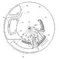
(試料分析用基板100)
図3Aおよび図3Bは、試料分析用基板100の平面図および分解斜視図である。試料分析用基板100は、回転軸101および回転軸に平行な方向に所定の厚さを有する板形状の基板100’を備える。本実施形態では、試料分析用基板100の基板100’は円形形状を有しているが、多角形形状、楕円形状、扇形形状等を有していてもよい。基板100’は、2つの主面100c、100dを有している。本実施形態では、主面100cおよび主面100dは互いに平行であり、主面100cおよび主面100dの間隔で規定される基板100’の厚さは、基板100’のどの位置でも同じである。しかし、主面100c、100dは、平行でなくてもよい。例えば、2つの主面の一部分が非平行または平行であってもよいし、全体的に非平行であってもよい。また、基板100’の主面100c、100dの少なくとも一方に凹部または凸部を有する構造を備えていてもよい。試料分析用基板100は、それぞれ基板100’内に位置する第1チャンバー102と、第2チャンバー103と、第3チャンバー104と、第1貯蔵チャンバー108と、第2貯蔵チャンバー109と、反応チャンバー107とを有する。各チャンバーの形状は、以下において特に言及しない限り、制限はなく、任意の形状を有していてもよい。第1チャンバー102を除き、各チャンバーは、概ね、基板100’の2つの主面に平行な上面及び下面と、これらの間に位置する4つの側面とによって規定された空間を有する。上面、下面および側面のうちの隣接する2つの面は、明瞭な稜線によって分けられていなくてもよい。例えば、各チャンバーの形状は扁平な球あるいは、回転楕円体であってもよい。(Sample analysis substrate 100)
3A and 3B are a plan view and an exploded perspective view of the
試料分析用基板100は、更に、それぞれ基板100’内に位置する第1流路110と、第2流路111と、第3流路112と、第4流路114と、第5流路115とを有する。第1流路110は第1チャンバー102と第2チャンバー103とを接続している。第2流路111は、第2チャンバー103と第3チャンバー104とを接続している。第3流路112は、反応チャンバー107と第2チャンバー103とを接続している。第4流路114は、第1貯蔵チャンバー108と第1チャンバー102とを接続している。第5流路115は、第1チャンバー102と第2貯蔵チャンバー109とを接続している。 The
流路を介したチャンバー間の液体の移送は、種々の方法で実現することが可能である。たとえば、重力による移送および毛細管力と回転による遠心力とによる移送を利用することができる。以下この2つの移送方法を概括的に説明する。 The liquid transfer between the chambers through the flow path can be realized by various methods. For example, transfer by gravity and transfer by capillary force and centrifugal force by rotation can be used. The two transfer methods will be generally described below.
たとえば、試料分析用基板100を回転軸Aが鉛直方向に対して0度より大きく90度以下の範囲で傾けて支持する。そして、試料分析用基板100の回転角度位置を変更することにより、液体が存在する移送元のチャンバーを、移送先のチャンバーよりも高い位置に配置させる。「高い」とは鉛直方向でより上にあることを言う。これにより、重力を利用して液体を他のチャンバーに移送し得る。この場合、チャンバー間を連結する流路は、毛管路ではない。「毛管路」は、毛細管現象により内部に液体を満たすことができる狭い空間を有する流路を指す。 For example, the
また、毛管路を利用し、液体を他のチャンバーに移送をすることもできる。毛管路の液体の移送について、毛細管空間ではないチャンバーAおよびチャンバーBと、チャンバーAとチャンバーBを接続する毛管路を有する構成を例に挙げて説明する。チャンバーAに保持された液体は、チャンバーAと毛管路と接続部分である開口に接触すると、液体は毛細管力により毛管路内に吸引され、その流路内部が液体で満たされる。しかしながら、流路内部の液体にかかる毛細管力以下の遠心力を流路内部の液体にかけることができる回転数(停止状態も含む)で試料分析用基板100を回転させると、毛管路内の液体は、チャンバーBへは移送されず、毛細管空間内に留まっている。このように毛細管現象により毛管路内部で液体を満たすには、チャンバーB側、すなわち、毛管路の出口側に空気孔(外部環境とチャンバーとの空気の通り道)を備えなければならない。また、チャンバーA、チャンバーBおよび毛管路といった閉鎖された空間内で毛細管現象による液体の移送を行うには、各チャンバーおよび流路内の気圧の関係から、チャンバーA側、すなわち毛管路の入口側にも空気孔を設けなければならない。そして、チャンバーBが、回転軸に対してチャンバーAよりも遠い位置に配置されていれば、この毛管路に液体が満たされている状態で、毛管路内部の液体にかかる毛細管力よりも大きい遠心力をかけることができる回転数で試料分析用基板100を回転させると、その遠心力によりチャンバーA中の液体をチャンバーBに移送することができる。 Also, the liquid can be transferred to another chamber using a capillary channel. The transfer of the liquid in the capillary channel will be described by taking as an example a configuration having chambers A and B that are not capillary spaces, and a capillary channel that connects the chamber A and the chamber B. When the liquid held in the chamber A comes into contact with the opening which is a connecting portion between the chamber A and the capillary channel, the liquid is sucked into the capillary channel by capillary force, and the inside of the channel is filled with the liquid. However, when the
液体を毛細管力および回転による遠心力によって移送する場合、例えば、直径60mmの試料分析用基板100を100rpmから8000rpmの範囲で回転させることができる。回転速度は各チャンバーおよび流路の形状、液体の物性、液体の移送や処理のタイミング等に応じて決定される。 When the liquid is transferred by capillary force and centrifugal force due to rotation, for example, the
本実施形態では、試料分析用基板100の基板100’は、ベース基板100aとカバー基板100bによって構成されている。第1チャンバー102、第2チャンバー103、第3チャンバー104、第1貯蔵チャンバー108、第2貯蔵チャンバー109および反応チャンバー107のそれぞれの空間はベース基板100a内に形成され、カバー基板100bでベース基板100aを覆うことにより、それぞれの空間の上部および下部が形成される。つまり、これらの空間は基板100’の内面によって規定されている。第1流路110、第2流路111、第3流路112、第4流路114および第5流路115もベース基板100aに形成されており、カバー基板100bでベース基板100aを覆うことにより、これらの流路の空間の上部および下部が形成される。本実施形態では、ベース基板100aおよびカバー基板100bがそれぞれ上面および下面と使用される。基板100’は、例えば、アクリル、ポリカーボネート、ポリスチレン等の樹脂によって生成され得る。 In the present embodiment, the
反応チャンバー107は、図1を参照して説明したように、磁性粒子固定化抗体305と、抗原306を含む検体と、標識抗体308とを反応させて、複合体310を形成させる反応場である。反応チャンバー107の形状に特に制限はない。反応チャンバー107と第3流路112との接続部分は、反応チャンバー107の回転軸101に平行な方向に位置する側面のうち、回転軸101から最も遠い側に位置する側面(最外周側面)か、または、最外周側面に隣接する側面であって、最外周側壁との接続位置を含む位置に設けられることが好ましい。反応チャンバー107中の液体を第2チャンバー103へ移送させるにあたり、反応チャンバー107中に液残りが生じることを抑制できるからである。なお、図3Aの例では、反応チャンバー107と第3流路112との接続部分は、最外周側面であって、最外周側面に隣接する一方の側面との境界位置に設ける構成を示している。 As described with reference to FIG. 1, the
本実施形態では、試料分析用基板100は、複合体310を形成させる反応場として、反応チャンバー107を備えている。磁性粒子固定化抗体305、抗原306を含む検体および標識抗体308の反応チャンバー107への移送には、種々の手段を採り得る。例えば、予め磁性粒子固定化抗体305、抗原306を含む検体および標識抗体308を混合させた混合溶液を量りとり、試料分析用基板100内の反応チャンバー107に混合溶液を注入してもよい。また、試料分析用基板100は、磁性粒子固定化抗体305、抗原306を含む検体および標識抗体308のそれぞれを保持するチャンバーと、それぞれのチャンバーと反応チャンバー107とが連結する流路(例えば、毛管路)を備えていてもよい。この場合、磁性粒子固定化抗体305、抗原306を含む検体および標識抗体308をそれぞれのチャンバーに量りとり、各チャンバーに注入された磁性粒子固定化抗体305、抗原306を含む検体および標識抗体308を反応チャンバー107に移送して反応チャンバー107中で混合し、複合体310を形成させてもよい。また、磁性粒子固定化抗体305や標識抗体308を乾燥させてもよい(以下、「ドライ化試薬」と称する。)。この場合、例えば、反応チャンバー107にドライ化試薬を保持させ、抗原306を含む検体溶液を含む液体で溶解させることで複合体310を形成させてもよい。また、測定時にあるチャンバーに保持されたドライ化試薬を所定の溶液で溶解させ、抗原306を含む検体溶液を反応チャンバー107中で混合させることで複合体310を形成させてもよい。 In the present embodiment, the
複合体310を含む溶液は、第3流路112を介して、第2チャンバー103へ移送される。 The solution containing the complex 310 is transferred to the
第2チャンバー103において、複合体310を含む溶液のB/F分離が行われる。このために、試料分析用基板100は、磁石106を含む。第2チャンバー103は、反応チャンバー107および後述する第1チャンバー102の部分102baよりも回転軸101に対して遠い側に位置している。 In the
第2チャンバー103の形状は特に限定されないが、第2チャンバー103と第2流路111との接続部分は、第2チャンバー103の回転軸101に平行な方向に位置する側面のうち、回転軸101から最も遠い側に位置する側面(最外周側面)か、または、最外周側面に隣接する側面であって、最外周側壁との接続位置を含む位置に設けられることが好ましい。第2チャンバー103中の液体を第3チャンバー104へ移送させるにあたり、第2チャンバー103中に液残りが生じることを抑制できるからである。なお、図3Aの例では、第2チャンバー103と第2流路111との接続部分は、最外周側面であって、最外周側面に隣接する一方の側面との境界位置に設ける構成を示している。 The shape of the
また、第2チャンバー103と第3流路112との接続部分は、第2チャンバー103の回転軸101に平行な方向に位置する側面のうち、回転軸101から最も近い側に位置する側面(最内周側面)か、または、最内周側面に隣接する側面であって、最内周側壁との接続位置を含む位置に設けられることが望ましい。なお、図3Aの例では、第2チャンバー103と第3流路112との接続部分は、最外周側面の一部に設ける構成を示している。 In addition, the connection portion between the
磁石106は、試料分析用基板100内において、第2チャンバー103の空間に近接して位置している。より具体的には、磁石106は、第2チャンバー103の4つの側面のうち、回転軸から最も遠くに位置する側面103bに近接して配置されている。磁石106はB/F分離に応じて取外しできるように構成されていてもよいし、試料分析用基板に着脱不能に取り付けられていてもよい。 The
試料分析用基板100における磁石106の配置は、第2チャンバー103の側面103bに近接する位置に限られない。磁石106によって、第2チャンバー103の壁面に磁性粒子を捕捉できれば、他の位置に磁石106を配置してもよい。例えば、第2チャンバー103の側面103b以外の上面や下面に近接する位置に磁石106を配置してもよい。すなわち、磁石106によって、第3チャンバー104の壁面に磁性粒子を捕捉できれば、その位置は特に限定されない。 The arrangement of the
磁石106を着脱可能に構成した場合には、例えば、基板100’は、磁石106を収納することができる収納室を備える。例えば、図3Cに示すように、基板100’は、主面100cに開口120aを有する凹状の収納室120を備えていてもよい。収納室120は磁石106を収納可能な空間を有する。開口120aaから収納室120に磁石106を挿入することにより、磁石106を基板100’に装填することができる。収納室120の開口120aは、主面100dに設けてもよいし、2つの主面100c、100dの間に位置する側面に設けてもよい。 In the case where the
また、磁石106を試料分析装置200に設けてもよい。例えば、試料分析装置200は、磁石106を有するターンテーブル201aを備えていてもよい。この場合、試料分析用基板100がターンテーブル201aの所の位置に配置すると、第3チャンバー104の側面103b近傍など、磁性粒子を捕捉できる位置に磁石106が配置される。 Further, the
磁石106を試料分析装置200に設ける他の例として、例えば、試料分析装置200は、磁石106および磁石106を移動させる駆動機構を備えていてもよい。この場合、試料分析用基板100は磁石106を保持する収納室を備え、B/F分離に応じて、駆動機構が試料分析用基板100の収納室に磁石106を挿入し、収納室内の磁石106を取り出してもよい。 As another example in which the
第1貯蔵チャンバー108は、B/F分離の際の洗浄に用いる洗浄液を貯留する。以下において詳細に説明するように、本実施形態の試料分析システム501では、B/F分離の際、複合体310を複数回洗浄することができる。このため、第1貯蔵チャンバー108は、洗浄回数に応じた容量の洗浄液を保持し得る。 The
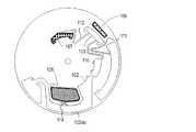
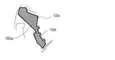
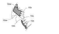
第1チャンバー102は、第1貯蔵チャンバー108に貯留されていた全洗浄液を保持し、1回の洗浄に使う所定の量の洗浄液を量り取る。このために、第1チャンバー102の空間は第2部分102aと、第1部分102bと、第2部分102aおよび第1部分102bとを接続する連結部分102cとを含む。 The
本実施形態では、第2部分102aの一部と第1部分102bとは、概ね、回転軸101を中心とする円周方向に配置されている。第2部分102aと第1部分102bとの間に、基板100’の内面によって構成される壁部分100fが位置している。壁部分100fは、第2部分102aと第1部分102bを区切る。連結部分102cは基板100’の壁部分100fと同じ半径方向上に位置し、かつ、壁部分100fよりも回転軸101側に位置している。連結部分102cは、毛細管現象によって液体で満たされることはなく、重力によって第1部分102bと第2部分102aとの間で液体を移動させる。 In the present embodiment, a part of the
第1部分102bは、回転軸101を中心とし、回転軸101と壁部分100fの回転軸に最も近い点100eとを結ぶ線分を半径とする円弧caよりも、外側に位置する(回転軸101から離れて位置する)部分102baを含む。この部分102baによって、1回の洗浄に使う所定の量の洗浄液を量り取ることができる。 The
また、回転軸から第1部分102bにおける第1流路110の接続位置までの距離は、回転軸101から壁部分100fの回転軸に最も近い点100eまでの距離よりも長い。このため、部分102baによって量り取られた洗浄液は回転による遠心力によって第1流路110から第2チャンバー103へ移送させることができる。 Further, the distance from the rotation axis to the connection position of the
本実施形態では、第1チャンバー102の空間の第2部分102aは、側部102aaと底部102abを含む。側部102aaは、回転軸101を中心とする円周方向において、第1貯蔵チャンバー108の側方に位置している。底部102abは、第1貯蔵チャンバー108よりも回転軸101から遠くに位置している。また、第2部分102aの、側部102aaの一部および底部102abの全体は、第1部分102bよりも回転軸101から遠くに位置している。 In the present embodiment, the
側部102aaは、好ましくは、円弧caよりも回転軸101側に位置する部分102aa’および外側に位置する部分102aa’’を含む。部分102aa’は、上述したように、第1部分102bと円周方向に隣接しており、連結部分102cと接続している。 The side portion 102aa preferably includes a portion 102aa 'located on the
第1チャンバー102の第2部分102aのうち、円弧caよりも外側(回転軸101から遠く)に位置する部分、つまり、部分102aa’’と底部102abとの合計の容積は、第1貯蔵チャンバー108に保持される洗浄液の全量よりも大きいことが好ましい。 Of the
第1チャンバー102の空間が底部102abを含むことで、試料分析用基板100が所定の角度で停止されている状態では、第4流路114に第1貯蔵チャンバー108に貯留されていた洗浄液の一部が毛細管現象により満たされる。そして、第4流路114に洗浄液が満たされた状態で試料分析用基板100を回転させることで、その遠心力によって第1貯蔵チャンバー108中の洗浄液は第4流路114を介して底部102abへ移送される。 When the
試料分析用基板100が所定の角度で保持されると、重力によって、第1チャンバー102の底部102abへ移送された洗浄液の一部が連結部分102cを通って第1部分102bへ流れ、第1部分102bの少なくとも一部を満たす。その後、試料分析用基板100を回転させると、第1部分102bを満たしている洗浄液に遠心力が働き、回転軸101と、壁部分100fの回転軸101に最も近い点100eとを結ぶ線分を半径とする円弧ca(図3A中、破線で示している)と、第1部分102bの洗浄液の液面とが一致するように、第1部分102bに保持されていた洗浄液のうち、余分な量が第2部分102aへ戻される。これによって、洗浄液の所定量が量り取られる。第1部分102bの、回転軸101と、壁部分100fの回転軸101に最も近い点100eとを結ぶ線分を半径とする円弧caより外側位置する部分の容積は、第1チャンバー102の容積の1/2以下である。詳細については、以下において説明する。 When the
なお、本実施形態では、第2部分102aとして、側部102aaの一部および底部102abを含む構成を示したが、第2部分102aは、回転軸101を中心とし、回転軸101と壁部分100fの回転軸101に最も近い点とを結ぶ線分を半径とする円弧よりも外側に位置する部分を含めばよい。 In the present embodiment, a configuration including a part of the side portion 102aa and the bottom portion 102ab is shown as the
第2チャンバー103は、B/F分離を行う場を提供する。試料分析用基板100が所定の角度で停止されている状態では、第3流路112に反応チャンバー107中の複合体310および未反応物を含む液体(以下反応液と呼ぶ)の一部が毛細管現象により満たされる。そして、第3流路112に反応液が満たされた状態で試料分析用基板100を第3流路112内部の液体にかかる毛細管力よりも大きい遠心力をかけることができる回転数で回転させることで、その遠心力によって反応チャンバー107中の反応液は第3流路112を介して第2チャンバー103へ移送される。 The
反応液が第2チャンバー103へ移送されると、反応液中の複合体310および未反応の磁性粒子固定化抗体305(以下、これら両方を指す場合には、単に磁性粒子311と呼ぶ)は、側面103bに近接して配置された磁石106の磁力によって、側面103b側に捕捉される。また、試料分析用基板100が所定の角度で停止されている状態では、第2流路111に第2チャンバー103中の反応液(磁石106によって側面103bに捕捉された磁性粒子311を除く)の一部が、毛細管現象により満たされ、その状態から試料分析用基板100を第2流路111内部の液体にかかる毛細管力よりも大きい遠心力をかけることができる回転数で回転させると、その遠心力によって、第2チャンバー103中の反応液(磁石106によって側面103bに捕捉された磁性粒子を除く)は、第2流路111を通って第3チャンバー104へ移送される。 When the reaction solution is transferred to the
第1チャンバー102において、一定量が量り取られた洗浄液は、毛細管現象により第1流路110を満たし、その後、試料分析用基板100を第1流路110内部の液体にかかる毛細管力よりも大きい遠心力をかけることができる回転数で回転させることで、その遠心力により第1流路110を通って第2チャンバー103へ移送される。このため、第2チャンバー103は、第1チャンバー102の第1部分102bの円弧より外側位置する部分の容積よりも大きい。 In the
第3チャンバー104は、試料分析用基板100を回転させ、その遠心力によって、第2流路111を通って第2チャンバー103から排出される液体を貯蔵する。このために、第3チャンバー104は、第2チャンバー103よりも回転軸101から遠くに位置している。 The
第2貯蔵チャンバー109は、第1チャンバー102に保持されていた洗浄液のうち、洗浄に使用されなかった分を貯める。第1チャンバー102と第2貯蔵チャンバー109とは、第5流路115によって接続されている。 The
第1チャンバー102、第2チャンバー103、第3チャンバー104、第1貯蔵チャンバー108、第2貯蔵チャンバー109および反応チャンバー107のそれぞれには少なくとも1つの空気孔118が設けられている。これにより、各チャンバー内が環境下の気圧に保たれ、毛管路およびサイフォン構造を用いることによって各流路が液体の移動・停止を制御し得る。また、第1貯蔵チャンバー108および反応チャンバー107には、検体溶液、反応溶液、洗浄液等などの液体を注入したり、排出するための開口119が設けられていてもよい。 Each of the
空気孔118および開口119は、各チャンバーにおいて、上面であって、回転軸101に近接する側面側に配置されていることが好ましい。これにより、各チャンバーに液体が満たされた状態で試料分析用基板100が回転しても、空気孔118および開口119が液体と接し、液体が、空気孔118および開口119から試料分析用基板100の外部へ移動するのを抑制することができる。空気孔118および開口119は、各チャンバーの側面部分に設けてもよい。 The
また、各チャンバーの空間は、回転軸101側に突出した凸状部分を有しており、凸状部分に空気孔118および開口119が位置していることが好ましい。この構成により、各チャンバーにおける空気孔118および開口119の位置を半径方向においてできるだけ回転軸101に近づけることができる。よって、試料分析用基板100が回転した状態において、空気孔118および開口119と接しないで、各チャンバーが保持し得る液体の量を増大させることができ、これらのチャンバーの空間のうち、液体の保持に利用できないデッドスペースを小さくすることができる。 Moreover, it is preferable that the space of each chamber has the convex part which protruded in the
次に図4を参照しながら各流路を説明する。第1流路110、第2流路111、第3流路112および第4流路114は、毛細管現象によって内部を液体で満たすことが可能である。具体的には、第1流路110、第2流路111、第3流路112および第4流路114は、それぞれ、毛細管現象により、第1チャンバー102、第2チャンバー103、反応チャンバー107および第1貯蔵チャンバー108に満たされた液体で内部を満たすことができる。つまり、第1流路110、第2流路111、第3流路112および第4流路114は、毛管路(capillary channel)あるいは毛細管(capillary tube)であることが好ましい。 Next, each flow path will be described with reference to FIG. The
例えば、第1流路110、第2流路111、第3流路112および第4流路114は、それぞれ流路が伸びる方向に垂直な断面において、0.1mm〜5mmの幅および50μm〜300μmの深さを有していてもよく、50μm以上(好ましくは50μm〜300μm)の幅および0.1mm〜5mmの深さを有していてもよい。これに対して、第5流路115および連結部100eは、重力によって液体が移動可能な程度に大きな断面積を有している。 For example, the
上述した流路が毛管路である場合、流路を規定する基板100’の内面、ならびに、流路が接続しているチャンバーの接続部分近傍の内面は、親水処理が施されていてもよい。親水処理によって毛細管力が大きく働く。親水処理は、例えば、上述した内面に、非イオン系、カチオン系、アニオン系または両イオン系の界面活性剤を塗布したり、コロナ放電処理を行ったり、物理的な微細凹凸を設けるなどによって行うことができる(例えば、特開2007−3361号公報を参照。)。 When the above-described channel is a capillary channel, the inner surface of the
また、第1流路110、第2流路111および第3流路112はサイフォンの原理によって、液体の移動を制御し得る。このために、サイフォン構造として、第1流路110、第2流路111および第3流路112はそれぞれ第1屈曲部および第2屈曲部を有している。第1屈曲部は回転軸101と反対側に凸形状を有し、第2屈曲部は回転軸101側に凸形状を有する。第1屈曲部は、流路が接続する2つチャンバーのうち、回転軸101に近い側に位置するチャンバーと、第2屈曲部との間に位置している。 Further, the
ここでいうサイフォンの原理とは、試料分析用基板100の回転により液体にかかる遠心力と流路の毛細管力とのバランスで送液制御が行われる。具体的に、反応チャンバー107から第2チャンバー103に液体が移送され、さらに第3チャンバー104に液体が移送される例で説明する。 The siphon principle here refers to liquid feeding control based on the balance between the centrifugal force applied to the liquid by the rotation of the
例えば、第2流路111がサイフォン構造を有しない毛管路である場合、試料分析用基板100の回転による遠心力で、反応チャンバー107から第3流路112を介して第2チャンバー103へ移送される過程において、第2チャンバー103へ移送された液体は、第2流路111の毛細管力により第2流路111内に液体が満たされる。この状態で、試料分析用基板100の回転が継続していると、液体は、第2チャンバー103中に保持されず、第3流路112を介して第3チャンバー104に移送されてしまう。ここでいう試料分析用基板100の回転は、第2流路111の毛細管力よりも強い遠心力をかけることができる回転数である。 For example, when the
一方、第2流路111がサイフォン構造を有していれば、反応チャンバー107から第2チャンバー103へ移送された液体は、第2流路111の毛細管力により、第2流路111中に液体が引き込まれる。しかしながら、試料分析用基板100の回転が継続して回転し、第2流路111の毛細管力よりも強い遠心力をかけることができる回転数で回転していれば、液体にかかる毛細管力よりも遠心力の方が強いため、第2流路111内全てを液体で満たされることはない。すなわち、第2流路111には、回転軸101に対して第2チャンバー103に存する液体の液面の距離と同じ高さまでしか液体が満たされない。そして、第2チャンバー103中の液体を第3チャンバー104へ移送したい場合には、試料分析用基板100の回転を、第2流路111の毛細管力以下の遠心力をかけることができる回転数(回転停止も含む)にすることで、毛細管力により第2流路111内全てに液体が満たされる。その後、第2流路111の毛細管力よりも強い遠心力をかけることができる回転数で試料分析用基板100を回転させると、第2チャンバー103内の液体を、第3チャンバー104へ移送させることができる。 On the other hand, if the
したがって、上述の回転数で反応チャンバー107から第2チャンバー103に液体を移送し、そのまま第3チャンバー104に液体を移送することなく、一旦、第2チャンバー103に液体を保持したい場合には、第2流路111をサイフォン構造で構成することが好ましい。 Therefore, when the liquid is transferred from the
第1流路110および第3流路112についても同様であるが、上述の液体制御が不要な場合であってもサイフォン構造を採用してもよい。 The same applies to the
サイフォン構造を構成するには、回転軸101と、回転軸101から遠くに位置するチャンバーの最も回転軸に近い側面との距離をR1とし、回転軸101から、第1屈曲部の最も回転軸101から遠い側に位置する点までの距離をR2とした場合、R1>R2(条件1)を満たすことが好ましい。 In order to configure the siphon structure, the distance between the
また、回転軸101に近くに位置するチャンバーに保持された液体が、遠心力によって、側面に偏って保持されている場合において、回転軸から液体の液面までの距離をR4とし、回転軸101から、第2屈曲部の最も回転軸101に近い側に位置する点までの距離をR3とした場合、R4>R3(条件2)を満たすことが好ましい。 In addition, when the liquid held in the chamber located near the
第1流路110、第2流路111および第3流路112について、距離R1〜R4をそれぞれ、距離1R1〜1R4、2R1〜2R4、3R1〜3R4とした場合、条件1、2は以下のように示される。
第1流路110
条件1:1R1>1R2
条件2:1R4>1R3
第2流路111
条件1:2R1>2R2
条件2:2R4>2R3
第3流路112
条件1:3R1>3R2
条件2:3R4>3R3When the distances R1 to R4 are the distances 1R1 to 1R4, 2R1 to 2R4, and 3R1 to 3R4 for the
Condition 1: 1R1> 1R2
Condition 2: 1R4> 1R3
Condition 1: 2R1> 2R2
Condition 2: 2R4> 2R3
Condition 1: 3R1> 3R2
Condition 2: 3R4> 3R3
第2流路111が条件1、2を満たしていることによって、反応チャンバー107から反応液を第2チャンバー103へ遠心力によって移送させる場合に、第2チャンバー103へ移送された反応液がそのまま第3チャンバー104へ移送されるのを防止し得る。また、第1チャンバー102から洗浄液を第2チャンバー103へ遠心力によって移送させる場合に、第2チャンバー103へ移送された洗浄液がそのまま第3チャンバー104へ移送されるのを防止し得る。 When the
なお、本実施形態では、前述の通り、第2流路111がサイフォン構造を有する毛管路である例を説明したが、第1流路110、第2流路111および第3流路112は、サイフォン構造を有さない毛管路または、重力を利用した流路であってもよい。 In the present embodiment, as described above, the example in which the
反応チャンバー107から第2チャンバー103を介して第3チャンバー104に液体を移送する過程において、第2流路111がサイフォン構造を有さない毛管路であって、第2チャンバー103に一旦、液体を保持するには、次のような構成であることが好ましい。まず、反応チャンバー107から第2チャンバー103へ液体を移送するにあたって、第2流路111中に液体が満たされた液体にかかる毛細管力以下の遠心力をかけることができる試料分析用基板100の回転数(停止状態も含む)で行わなければならない。この場合、第3流路112は、重力を利用した流路であることが好ましい。また、第3流路112が重力を利用した流路であることから、反応チャンバー107の側面部分107b(図3Aに示す)は、試料分析用基板100を所定の角度で保持した場合に、側面部分107bで液体を保持できるように側面部分107bを凹形状となるように形成することが好ましい。この場合、反応チャンバー107から第2チャンバー103へ液体を移送するには、側面部分107bの凹部に保持された液体が、重力により第3流路112を介して移動するように試料分析用基板100の回転角度を変更することで行われる。 In the process of transferring the liquid from the
一方、反応チャンバー107から第2チャンバー103を介して第3チャンバー104に液体を移送する過程において、第2流路111が重力を利用した流路であって、第2チャンバー103に一旦、液体を保持する場合には、次のような構成であることが好ましい。第3流路112は、毛管路(サイフォン構造を含む)であっても重力を利用した流路のいずれでもよいが、第3流路112が重力を利用した流路である場合、第2チャンバー103の側面部分103b(図3Aに示す)は、試料分析用基板100を所定の角度で保持した場合に、側面部分107bで液体を保持できるように側面部分107bを凹形状となるように形成することが好ましい。この場合、第2チャンバー103から第3チャンバー104へ液体を移送するには、側面部分103bの凹部に保持された液体が、重力により第2流路111を介して移動するように試料分析用基板100の回転角度を変更することで行われる。 On the other hand, in the process of transferring the liquid from the
以上のとおり、第1流路110、第2流路111および第3流路112はの構成は、種々の方式を採用することができる。 As described above, the
本実施形態では、第1流路110および第3流路112もサイフォン構造を備えている。しかし、第1流路110および第3流路112はサイフォン構造を備えていなくてもよい。また、本実施形態では、第4流路114は、サイフォンを構成していないが、サイフォンを構成していてもよい。以下において詳細に説明するように、第1流路110、第2流路111および第3流路112におけるサイフォンの構造には、試料分析用基板100の回転による遠心力に対してサイフォンの原理が働く。 In the present embodiment, the
(試料分析システム501の動作)
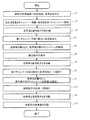
試料分析システム501の動作を説明する。図5は、試料分析システム501の動作を示すフローチャートである。以下の工程に先立ち、試料分析用基板100を試料分析装置200に装填し、試料分析用基板100の原点を検出する。(Operation of sample analysis system 501)
The operation of the
[ステップS1]
まず、図6に示すように、洗浄液を試料分析用基板100の第1貯蔵チャンバー108に導入する。また、反応チャンバー107に、磁性粒子固定化抗体305と、抗原306を含む検体と、標識抗体308を導入する。例えば、反応チャンバー107に磁性粒子固定化抗体305を含む液体が保持されており、試料分析用基板100に設けられた図示しないチャンバーが抗原306および標識抗体308を含む液体をそれぞれ別々に保持しており、試料分析用基板100の回転による遠心力でこれらが反応チャンバー107へ移送されてもよい。反応チャンバー107において、磁性粒子固定化抗体305と、抗原306を含む検体と、標識抗体308とを抗原抗体反応により、同時に反応させて複合体310を形成させる。この時点で第4流路114および第3流路112は、毛細管現象によって、それぞれ、洗浄液および複合体310を含む反応液で満たされている。[Step S1]
First, as shown in FIG. 6, the cleaning liquid is introduced into the
[ステップS2]
複合体310が生成した後、試料分析用基板100を回転させ、複合体310を含む反応液を第2チャンバー103へ移動させる。この際、第3流路112は、毛細管現象によって、反応液で満たされている。このため、反応チャンバー107の複合体310を含む反応に、回転により第3流路112内の反応液にかかる毛細管力よりも強い遠心力が働くと、反応液は第2チャンバー103へ移送される。第2チャンバー103へ移送された反応液は、試料分析用基板100が回転している状態では、続いて第3チャンバー104へ移送されることはない。前述したように第2流路111がサイフォンを構成しているため、遠心力に逆らって、液体が、第2流路111を回転軸101に向かう方向へ移動しないからである。[Step S2]
After the complex 310 is generated, the
試料分析用基板100の回転速度は、回転による遠心力が生じることにより、反応液等の液体が重力によって移動せず、各毛管路の毛細管力よりも強い遠心力をかけられるような速度が設定される。以下、遠心力を利用する回転には、この回転速度が設定される。 The rotation speed of the
反応液の移動と同時に、洗浄液が第1貯蔵チャンバー108から第4流路114を通って、第1チャンバーの第1部分の底部102abへ移送される。底部102abの容量(空間の大きさ)および洗浄液の量によっては、洗浄液は、側部102aaの一部を満たしてもよい。 Simultaneously with the movement of the reaction liquid, the cleaning liquid is transferred from the
反応液および洗浄液をそれぞれすべて第2チャンバー103および第1チャンバー102へ移送させた後、所定の角度で試料分析用基板100を停止させる。図7に示すように、例えば、所定の角度とは、試料分析用基板100において、第1チャンバー102の第1部分の底部102abが下方に位置する角度Aである。以下、分かりやすさのため、図7に示すように、回転軸101が重力方向から角度θで傾斜して保持される試料分析用基板100において、回転軸101の鉛直方向を基準として、試料分析用基板100の角度を示す。この時点で第2流路111は、毛細管現象によって、反応液で満たされている。角度Aは、第1チャンバー102の第2部分102aにある洗浄液が重力で第1部分102bへ移動しない角度範囲から選ばれる。 After the reaction solution and the cleaning solution are all transferred to the
[ステップS3]
試料分析用基板100を回転させる。回転にともない遠心力が発生し、第2チャンバー103内の反応液および磁性粒子311に働く。この遠心力は、図3Aに示すように、液体及び複合体が第2チャンバー103の側面103b側へ移動するように働く。遠心力が働く方向は、磁性粒子311が磁石106から受ける吸引力の方向と一致する。このため、複合体310は、強く側面103bに押し付けられる。[Step S3]
The
遠心力を受けた反応液は第2流路111から排出され、第3チャンバー104へ移送される。遠心力および磁石106の吸引力の和によって、磁性粒子311は側面103bに強く押し付けられ、捕捉される。このため、反応液のみが第2流路111から排出され、磁性粒子311は第2チャンバー103にとどまる。 The reaction solution that has received the centrifugal force is discharged from the
この時、第1チャンバー102の第1部分102bの底部102abに位置していた洗浄液は、遠心力によって底部102abの回転軸101から遠くに位置する側面側に押し付けられるため、洗浄液は、実質的に第1部分102b内にとどまっている。 At this time, since the cleaning liquid located at the bottom 102ab of the
図8に示すように、液体が第3チャンバー104へすべて移動した後、例えば、角度Bで試料分析用基板100の回転を停止させる。これにより、反応液と磁性粒子311とが分離される。具体的には、反応液は、第3チャンバー104へ移動し、磁性粒子311は第2チャンバー103にとどまる。図8に示すように、試料分析用基板100の回転が停止しても磁石106から受ける吸引力により、磁性粒子311は、側面103bに集まったままの状態を維持し得る。角度Bは角度Aと同じであってもよいし、次のステップの角度Cと一致してもよい。この場合には、基板の回転の停止とともに第1チャンバー102の第2部分102aにある洗浄液が重力で第1部分102bへ移動する。 As shown in FIG. 8, after all the liquid has moved to the
[ステップS4(工程(a))]
図9に示すように、試料分析用基板100を少し回転させ角度C(第1の角度)で停止させる。これにより、第1チャンバー102の第1部分102bが第2部分102aよりも重力方向において下に位置し、第2部分102aの洗浄液の一部が第1チャンバー102内において重力によって移し、第1部分102bの少なくとも一部を満たす。第1部分102bを確実に洗浄液で満たすよう、角度Cを中心として、時計回りおよび反時計回りに交互に数度程度回転させる、つまり揺動させてもよい。これにより図9に示すように、例えば、第1部分102bおよび第2部分102aの側部102aaが洗浄液で満たされる。第1部分102bが洗浄液で満たされると、第1流路110は毛細管現象により洗浄液を引き込む。すなわち、第1流路110は、毛細管現象によって、洗浄液で満たされている。角度Cは、重力によって洗浄液を第2部分102aから第1部分102bへ移動させることができる角度であればよい。[Step S4 (Process (a))]
As shown in FIG. 9, the
[ステップS5(工程(b))]
続いて、試料分析用基板100を回転させる。図10Aおよび図10Bに示すように、回転による遠心力が第1部分102bおよび第2部分102aの側部102aaにある洗浄液に働く。遠心力は、回転軸101から遠ざかるように洗浄液に働く。このため、図10Cに示すように、第1部分102bに位置する洗浄液は、連結部分102cを通って第2部分102aの側部102aaへ移動する。第2部分102aの側部102aaにある洗浄液は、より回転軸から離れて位置する底部102abへ移動する。その結果、回転軸101と、壁部分100fの回転軸101に最も近い点100eとを結ぶ線分を半径とする円弧caと、第1部分102bの洗浄液の液面とが一致するように、第1部分102bに保持されていた洗浄液のうち、余分な量が第2部分102aへ戻される。これによって、第1部分102bにおいて洗浄液の所定量が量り取られる。量り取られた洗浄液は、回転による遠心力によって、図10Dに示すように第1流路110を介して第2チャンバー103へ移送される。[Step S5 (Step (b))]
Subsequently, the
[ステップS6(工程(e))]
洗浄液が第2チャンバー103へ移動したら、例えば、図11に示すように、角度D(第3の角度)で試料分析用基板100の回転を停止させる。これにより、第2チャンバー103に捕捉されていた磁性粒子311が洗浄液で洗浄される。また、第2チャンバー103の洗浄液の一部が毛細管現象によって第2流路111に移動する。[Step S6 (Process (e))]
When the cleaning liquid moves to the
[ステップS7(工程(f))]
試料分析用基板100を回転させる。回転にともない遠心力が発生し、第2チャンバー103内の洗浄液が第2流路111を通って第3チャンバー104へ移送される。遠心力および磁石106の吸引力の和によって、磁性粒子311は側面103bに強く押し付けられ、捕捉される。このため、図12に示すように、洗浄液のみが第2流路111から排出され、磁性粒子311は第2チャンバー103にとどまる。[Step S7 (Step (f))]
The
一方、第1チャンバー102中の洗浄液は、遠心力により、概ね第2部分102aで保持された状態に保たれる。したがって、第1チャンバー102中の洗浄液から第2チャンバー103への移送は実質的に生じない。 On the other hand, the cleaning liquid in the
[ステップS8(工程(c))]
実質的に、ステップS4と同じである。図13に示すように、試料分析用基板100を角度E(第2の角度)で停止させる。これにより、第1チャンバー102の第1部分102bが第2部分102aよりも重力方向において下に位置し、第2部分102aの洗浄液の一部が第1チャンバー102内において重力によって移し、第1部分102bの少なくとも一部を満たす。第1部分102bを確実に洗浄液で満たすよう、角度Eを中心として、時計回りおよび反時計回りに数度程度回転させる、つまり揺動させてもよい。これにより例えば、第1部分102bおよび第2部分102aの側部102aa一部が洗浄液で満たされる。第1部分102bが洗浄液で満たされると、第1流路110は、毛細管現象により、洗浄液を引き込む。すなわち、第1流路110は、毛細管現象によって、洗浄液で満たされている。角度Eは、重力によって洗浄液を第2部分102aから第1部分102bへ移動させることができる角度であればよい。角度Eは、角度Cとおなじであってもよい。第1チャンバー102において保持している洗浄液がステップS4のときより少なくなっているため、角度Aを基準として角度Cより大きな角度で停止させてもよい。[Step S8 (Process (c))]
Substantially the same as step S4. As shown in FIG. 13, the
[ステップS9(工程(d))]
続いて、試料分析用基板100を回転させる。ステップS5で説明したように、回転による遠心力が第1部分102bおよび第2部分102aの側部102aaにある洗浄液に働く。このため、第1部分102bに位置する洗浄液は、連結部分102cを通って第2部分102aの側部102aaへ移動する。第2部分102aの側部102aaにある洗浄液は、より回転軸から離れて位置する底部102abへ移動する。その結果、第1部分102bに保持されていた洗浄液のうち、余分な量が第2部分102aへ戻される。これによって、第1部分102bにおいて洗浄液の所定量が量り取られる。また、第1部分102bに保持された洗浄液のうち、余分な量は第2部分102aへ戻される。量り取られた洗浄液は、回転による遠心力によって、図10Dに示すように、第1流路110を介して第2チャンバー103へ移送される。とともに、概ね所定量が量り取られた洗浄液は、第1流路110を介して第2チャンバー103へ移送される。[Step S9 (Process (d))]
Subsequently, the
[ステップS10(工程(g))]
洗浄液が第2チャンバー103へ移動したら、例えば、図14に示すように、角度F(第4の角度)で試料分析用基板100の回転を停止させる。これにより、第2チャンバー103に捕捉されていた磁性粒子311が再度洗浄液で洗浄される。また、第2チャンバー103の洗浄液の一部が毛細管現象によって第2流路111に移動する。[Step S10 (Step (g))]
When the cleaning liquid moves to the
[ステップS11(工程(h))]
試料分析用基板100を回転させる。回転にともない遠心力が発生し、第2チャンバー103内の洗浄液が第2流路111を通って第3チャンバー104へ移送される。遠心力および磁石106の吸引力の和によって、磁性粒子311は側面103bに強く押し付けられ、捕捉される。このため、図15に示すように、洗浄液のみが第2流路111から排出され、磁性粒子311は第2チャンバー103にとどまる。[Step S11 (Process (h))]
The
この時、第1チャンバー102の第1部分102bの底部102abに位置していた洗浄液は、遠心力によって底部102abの回転軸101から遠くに位置する側面側に押し付けられるため、洗浄液は、実質的に第1部分102b内にとどまっている。 At this time, since the cleaning liquid located at the bottom 102ab of the
[ステップS12]
図16に示すように、洗浄液が第3チャンバー104へすべて移動した後、例えば、角度Gで試料分析用基板100の回転を停止させる。角度Gは、第1チャンバー102に残っている洗浄液が重力によって、第5流路115を通って第2貯蔵チャンバー109へ移動し得る角度が選択される。[Step S12]
As shown in FIG. 16, after all the cleaning liquid has moved to the
以上の工程によって、B/F分離、具体的には、磁性粒子311と種々の未反応物とが分離される。 Through the above steps, B / F separation, specifically, the
その後、光学測定ユニット207を用いて、磁性粒子311に含まれる複合体310に結合した標識抗体308の標識物質307に応じた色素、発光、蛍光等のシグナルを検出する。これにより、抗原306の検出、抗原306の濃度の定量等を行うことができる。 Thereafter, using the
このように本実施形態の試料分析用基板、試料分析装置及び試料分析システムによれば、同じチャンバーに、液体を複数回に分けて、導入することができる。このため、試料分析用基板を用いてB/F分離をする場合、十分な洗浄を行うことができる。また、この動作は、試料分析用基板の回転および停止の制御と、停止時の角度の制御によって、実現し得る。このため、大型の分析機器を用いたり、操作者が手動で操作することなく、B/F分離を含む複雑な反応ステップを介して検体中の成分の分析が行われる分析法に好適に適用可能である。 As described above, according to the sample analysis substrate, sample analysis apparatus, and sample analysis system of the present embodiment, the liquid can be introduced into the same chamber in a plurality of times. For this reason, when performing B / F separation using the sample analysis substrate, sufficient cleaning can be performed. This operation can be realized by controlling the rotation and stop of the sample analysis substrate and controlling the angle at the time of stop. For this reason, it can be suitably applied to analysis methods in which components in a sample are analyzed through complex reaction steps including B / F separation without using a large analytical instrument or manually operated by an operator. It is.
なお、上記実施形態では、B/F分離の洗浄の例を説明したが、本実施形態の試料分析用基板、試料分析装置及び試料分析システムは、洗浄液以外の溶液を、上述したように複数回に分けて同じチャンバーへ導入する種々の試料分析方法へ適用可能である。また、上記実施形態では、液体のチャンバーへの導入を続けて行っているが、試料分析用基板の回転および停止の制御と、停止時の角度の制御を適切に行うことにより、間に他の工程を含めることも可能である。 In the above-described embodiment, an example of cleaning for B / F separation has been described. However, the sample analysis substrate, the sample analysis apparatus, and the sample analysis system according to the present embodiment apply a solution other than the cleaning solution a plurality of times as described above. It can be applied to various sample analysis methods that are introduced into the same chamber separately. In the above embodiment, the liquid is continuously introduced into the chamber. However, by appropriately controlling the rotation and stop of the sample analysis substrate and the angle at the time of stop, the other can be performed in between. It is also possible to include a process.
また、上記実施形態では2回洗浄を行っているが、必要に応じて3回以上行ってもよい。 In the above embodiment, the cleaning is performed twice, but may be performed three or more times as necessary.
また、上記実施形態では、磁性粒子を用いて試料の分析を行う例を説明したが、本開示の試料分析用基板、試料分析装置、試料分析システムおよび試料分析システム用プログラムは、磁性粒子を用いた試料の分析に限られない。例えば、1次抗体が固定化される対象は、磁性粒子ではなく、チャンバー内の壁面であってもよい。 In the above embodiment, an example in which a sample is analyzed using magnetic particles has been described. However, the sample analysis substrate, the sample analysis device, the sample analysis system, and the sample analysis system program of the present disclosure use magnetic particles. It is not limited to the analysis of the sample. For example, the target to which the primary antibody is immobilized may be a wall surface in the chamber instead of the magnetic particles.
具体的には、チャンバーがポリスチレンやポリカーボネートといった素材で構成されている場合、チャンバー内の壁面に物理吸着により1次抗体を固定させることができる。このため、チャンバー内で抗原や標識抗体とのサンドイッチ型の結合反応を行わせることができる。また、チャンバー内の壁面に1次抗体と結合可能な官能基(例えば、アミノ基やカルボキシル基)を有し、化学結合により1次抗体を固定化させることができる。これにより、チャンバー内で抗原や標識抗体とのサンドイッチ型の結合反応を行わせることができる。また、チャンバー内の壁面に金属基板を設け、SAMを用いて1次抗体を金属基板に結合させることにより、1次抗体を固定させることができる。これにより、チャンバー内で抗原や標識抗体とのサンドイッチ型の結合反応を行わせることができる。 Specifically, when the chamber is made of a material such as polystyrene or polycarbonate, the primary antibody can be immobilized on the wall surface in the chamber by physical adsorption. For this reason, a sandwich-type binding reaction with an antigen or a labeled antibody can be performed in the chamber. Moreover, it has a functional group (for example, amino group or carboxyl group) capable of binding to the primary antibody on the wall surface in the chamber, and the primary antibody can be immobilized by chemical bonding. Thereby, a sandwich-type binding reaction with an antigen or a labeled antibody can be performed in the chamber. Moreover, a primary substrate can be fixed by providing a metal substrate on the wall surface in the chamber and binding the primary antibody to the metal substrate using SAM. Thereby, a sandwich-type binding reaction with an antigen or a labeled antibody can be performed in the chamber.
一次抗体をチャンバーの壁面に物理吸着や化学結合で固定させる形態は、例えば、色素、化学発光または蛍光のシグナルを検出する測定系に使用することができる。一方、一次抗体を金属基板に固定させる形態は、シグナルとして、主に電気化学的シグナル(例えば、電流)、電気化学発光のシグナルを検出する測定系に使用することができる。 The form in which the primary antibody is immobilized on the wall surface of the chamber by physical adsorption or chemical bonding can be used, for example, in a measurement system that detects a dye, chemiluminescence, or fluorescence signal. On the other hand, the form in which the primary antibody is immobilized on a metal substrate can be used in a measurement system that mainly detects an electrochemical signal (for example, current) or an electrochemiluminescence signal as a signal.
これらの場合、図3に示した磁石106は不要である。また、複合体310形成の反応場は反応チャンバー107ではなく、第3チャンバー104である。したがって、一次抗体は、第3チャンバー104の壁面に固定される。また、本開示の試料分析用基板、試料分析装置、試料分析システムおよび試料分析システム用プログラムは、非競合法(サンドイッチイムノアッセイ法)だけでなく、競合法、ハイブリダイゼーションによる遺伝子検出法にも適用可能である。 In these cases, the
本願に開示された試料分析用基板、試料分析装置、試料分析システムおよび試料分析システム用プログラムは、種々の反応を利用した検体中の特定成分の分析に適用可能である。 The sample analysis substrate, sample analysis apparatus, sample analysis system, and sample analysis system program disclosed in the present application can be applied to analysis of a specific component in a specimen using various reactions.
100 試料分析用基板
100’ 基板
100a ベース基板
100b カバー基板
100d 壁部分
101 回転軸
102 第1チャンバー
102a 第2部分
102aa側部
102ab底部
102b 第1部分
102c 連結部分
103 第2チャンバー
103b 側面
104 第3チャンバー
106 磁石
107 反応チャンバー
108 第1貯蔵チャンバー
109 第2貯蔵チャンバー
110 第1流路
111 第2流路
112 第3流路
114 第4流路
115 第5流路
118 空気孔
119 開口
200 試料分析装置
201 モータ
201a ターンテーブル
203 原点検出器
204 回転角度検出回路
205 制御回路
206 駆動回路
207 光学測定ユニット
302 磁性粒子
304 一次抗体
305 磁性粒子固定化抗体
306 抗原
307 標識物質
308 標識抗体
310 複合体
501 試料分析システム100
Claims (17)
Translated fromJapanese回転軸を有する基板と、
前記基板内に位置し、液体を保持するための液体を貯留する第1貯蔵チャンバーと、
前記基板内に位置し、前記液体を保持するための第1空間を有する第1チャンバーと、
前記基板内に位置し、前記第1チャンバーから排出される前記液体を保持するための第2空間を有する第2チャンバーと、
前記基板内に位置しており、前記第1チャンバーおよび前記第2チャンバーを接続する経路を有し、毛細管現象により前記第1空間内に保持された液体で満たすことが可能な第1流路と、
前記基板内に位置しており、前記第1貯蔵チャンバーおよび前記第1チャンバーを接続する経路を有し、毛細管現象により前記第1貯蔵チャンバーに貯留された液体で満たすことが可能な第4流路と、
を備え、
前記第1チャンバーの第1空間は、第1部分および第2部分と、前記第1部分および前記第2部分の間に位置しており前記第1部分および前記第2部分を連結する連結部分とを有し、
前記基板は、第1空間の前記第1部分および前記第2部分を区切る壁部分を有し、
前記第2チャンバーは前記第1チャンバーの第1部分よりも回転軸から遠くに位置し、
前記第1空間の前記連結部分は、前記基板の前記壁部分よりも前記回転軸側に位置し、
前記第1空間の第1部分の、前記回転軸に平行な方向から見て、前記回転軸を中心とし、前記回転軸と前記壁部分の前記回転軸に最も近い点とを結ぶ線分を半径とする円の外側位置する部分の容積は、前記第1空間の1/2以下であり、
前記第1空間の第2部分は、前記回転軸を中心とする円周方向において、前記第1貯蔵チャンバーの側方に位置している側部と、前記第1貯蔵チャンバーよりも前記回転軸から遠くに位置する底部とを含み、
前記側部の一部および前記底部の全体は、前記第1部分よりも回転軸から遠くに位置しており、
前記第4流路は、前記第2空間の前記底部と接続され、
前記第1流路は、前記第1空間の前記第1部分と接続されている、試料分析用基板。A sample analysis substrate that transfers liquid by rotational movement,
A substrate having a rotation axis;
A first storage chamber located in the substrate and storing a liquid for holding the liquid;
A first chamber having a first space for located in said substrate, for holdingthe liquid;
A second chamber located within the substrate and having a second space for holding the liquid discharged from the first chamber;
A first flow path located in the substrate, having a path connecting the first chamber and the second chamber, and capable of being filled with a liquid held in the first space by capillary action; ,
A fourth flow path located in the substrate, having a path connecting the first storage chamber and the first chamber, and capable of being filled with a liquid stored in the first storage chamber by capillary action When,
With
The first space of the first chamber includes a first part and a second part, a connecting part that is located between the first part and the second part, and connects the first part and the second part. Have
The substrate has a wall portion that separates the first portion and the second portion of the first space;
The second chamber is located farther from the axis of rotation than the first portion of the first chamber;
The connecting portion of the first space is located closer to the rotating shaft than the wall portion of the substrate,
A radius of a line segment of the first portion of the first space connecting the rotation axis and a point closest to the rotation axis of the wall portion with the rotation axis as a center when viewed from a direction parallel to the rotation axis. The volume of the portion located outside the circle is ½ or less of the first space,
The second portion of the first space has a side portion positioned on the side of the first storage chamber in a circumferential direction around the rotation axis, and the rotation axis more than the first storage chamber. Including a bottom located far away,
A part of the side part and the whole of the bottom part are located farther from the rotation axis than the first part,
The fourth flow path is connected to the bottom of the second space;
The sample analysis substrate, wherein the first flow path is connected to the first portion of the first space.
記回転軸に最も近い点とを結ぶ線分を半径とする円弧よりも外側に位置する部分を含む、請求項1から3のいずれかに記載の試料分析用基板。The second portion of the first space is located outside an arc centered on the rotation axis and having a radius that is a line segment connecting the rotation axis and a point of the wall portion closest to the rotation axis. The substrate for sample analysis according to claim 1, comprising:
前記基板内に位置しており、前記第2チャンバーおよび前記第3チャンバーを接続する経路を有し、毛細管現象により前記第2空間内に保持された液体で満たすことが可能な第2流路と、
をさらに備える請求項1から6のいずれかに記載の試料分析用基板。A third chamber in the substrate, which is located farther from the rotation axis than the second chamber and has a third space for holding the liquid discharged from the second chamber;
A second channel located in the substrate, having a path connecting the second chamber and the third chamber, and capable of being filled with a liquid held in the second space by capillary action; ,
The substrate for sample analysis according to any one of claims 1 to 6, further comprising:
前記回転軸から前記第3チャンバーまでの距離は、前記回転軸から前記第1屈曲部の頂点までの距離より長く、
前記回転軸から前記第3チャンバーに保持された液体の、前記基板の回転による遠心力で形成される液面までの距離は、前記回転軸から前記第2屈曲部の頂点までの距離より長い請求項7に記載の試料分析用基板。The second flow path includes a first bent portion that is convex on the opposite side of the rotation axis and a second bent portion that is convex on the rotation axis side, and the first bent portion is the second bent portion. Located between the second chamber,
The distance from the rotation axis to the third chamber is longer than the distance from the rotation axis to the apex of the first bent portion,
The distance from the rotating shaft to the liquid surface formed by the centrifugal force of the substrate rotated by the liquid held in the third chamber is longer than the distance from the rotating shaft to the apex of the second bent portion. Item 8. The sample analysis substrate according to Item 7.
前記回転軸から前記第2チャンバーまでの距離は、前記回転軸から前記第1屈曲部の頂点までの距離より長く、
前記回転軸から前記第1チャンバーに保持された液体の、前記基板の回転による遠心力で形成される液面までの距離は、前記回転軸から前記第2屈曲部の頂点までの距離より長い
請求項8に記載の試料分析用基板。The first flow path includes a first bent portion that is convex on the opposite side to the rotation axis and a second bent portion that is convex on the rotation axis side, and the first bent portion is the second bent portion. Located between the first chamber and
The distance from the rotation axis to the second chamber is longer than the distance from the rotation axis to the apex of the first bent portion,
The distance from the rotating shaft to the liquid surface formed by the centrifugal force of the rotation of the substrate of the liquid held in the first chamber is longer than the distance from the rotating shaft to the apex of the second bent portion. Item 9. The sample analysis substrate according to Item 8.
回転軸を有する基板と、
前記基板内に位置し、液体を保持するための第1空間を有する第1チャンバーと、
前記基板内に位置し、前記第1チャンバーから排出される前記液体を保持するための第2空間を有する第2チャンバーと、
前記基板内に位置しており、前記第1チャンバーおよび前記第2チャンバーを接続する経路を有し、毛細管現象により前記第1空間内に保持された液体で満たすことが可能な第1流路と、
前記第2チャンバーに近接して位置する磁石と、
を備え、
前記第1チャンバーの第1空間は、第1部分および第2部分と、前記第1部分および前記第2部分の間に位置しており前記第1部分および前記第2部分を連結する連結部分とを有し、
前記基板は、第1空間の前記第1部分および前記第2部分を区切る壁部分を有し、
前記第2チャンバーは前記第1チャンバーの第1部分よりも回転軸から遠くに位置し、
前記第1空間の前記連結部分は、前記基板の前記壁部分よりも前記回転軸側に位置し、
前記第1空間の第1部分の、前記回転軸に平行な方向から見て、前記回転軸を中心とし、前記回転軸と前記壁部分の前記回転軸に最も近い点とを結ぶ線分を半径とする円の外側位置する部分の容積は、前記第1空間の1/2以下であり、
前記第1流路は、前記第1空間の前記第1部分と接続されている、試料分析用基板と、
重力方向に対して0°より大きく90°以下の角度で前記回転軸を傾斜させた状態で、前記試料分析用基板を前記回転軸周りに回転させるモータ、
前記モータの回転軸の角度を検出する回転角度検出回路、
前記回転角度検出回路の検出結果に基づき、前記モータの回転および停止時の角度を制御する駆動回路、および
演算器、メモリおよびメモリに記憶され、前記演算器に実行可能なように構成されたプログラムを含み、前記プログラムに基づき、前記モータ、前記回転角度検出回路、および前記駆動回路の動作を制御する制御回路
を有する試料分析装置と、
を備えた試料分析システムであって、
前記プログラムは、
前記第1チャンバーに液体が充填された試料分析用基板が前記試料分析装置のターンテーブルに載置された場合において、
(a) 前記試料分析用基板を所定の第1の角度で停止させることにより前記液体の一部を前記第1チャンバー内において重力によって移動させ、前記第1チャンバーの前記第1部分の少なくとも一部を前記液体の一部で満たし、かつ、毛細管現象によって、前記液体の他の一部を前記第1流路に移送させ、
(b) 前記試料分析基板を基板の回転による遠心力で、前記第1流路に満たされた液体にかかる毛細管力よりも強い遠心力が働く速度で回転させることによって、前記第1部分で前記液体の一部を秤量するとともに、過剰な液体を前記第2部分へ移動させることによって残りの液体を前記第2部分に保持し、かつ、秤量した前記第1部分にある前記液体の一部を、前記第1流路を通って前記第2チャンバーへ移動させ、
(c) 前記試料分析用基板を所定の第2の角度で停止させることにより前記残りの液体の一部を前記第1チャンバー内において重力によって移動させ、前記第1チャンバーの前記第1部分の少なくとも一部を前記残りの液体の一部で満たし、かつ、毛細管現象によって、前記残りの液体の他の一部を前記第1流路に移送させ、
(d) 前記試料分析基板を基板の回転による遠心力で、前記第1流路に満たされた液体にかかる毛細管力よりも強い遠心力が働く速度で回転させることによって、前記第1部分で前記残りの液体の一部を秤量するとともに、過剰な液体を前記第2部分へ移動させることによって余剰の液体を前記第2部分に保持し、かつ、秤量した前記第1部分にある前記残りの液体の一部を、前記第1流路を通って前記第2チャンバーへ移動させる、
工程を含む、試料分析システム。A sample analysis substrate that transfers liquid by rotational movement,
A substrate having a rotation axis;
A first chamber located within the substrate and having a first space for holding a liquid;
A second chamber located within the substrate and having a second space for holding the liquid discharged from the first chamber;
A first flow path located in the substrate, having a path connecting the first chamber and the second chamber, and capable of being filled with a liquid held in the first space by capillary action; ,
A magnet positioned proximate to the second chamber;
With
The first space of the first chamber includes a first part and a second part, a connecting part that is located between the first part and the second part, and connects the first part and the second part. Have
The substrate has a wall portion that separates the first portion and the second portion of the first space;
The second chamber is located farther from the axis of rotation than the first portion of the first chamber;
The connecting portion of the first space is located closer to the rotating shaft than the wall portion of the substrate,
A radius of a line segment of the first portion of the first space connecting the rotation axis and a point closest to the rotation axis of the wall portion with the rotation axis as a center when viewed from a direction parallel to the rotation axis. The volume of the portion located outside the circle is ½ or less of the first space,
The first flow path is connected to the first portion of the first space, the sample analysis substrate,
A motor that rotates the sample analysis substrate around the rotation axis in a state where the rotation axis is inclined at an angle of greater than 0 ° and not more than 90 ° with respect to the direction of gravity;
A rotation angle detection circuit for detecting an angle of a rotation shaft of the motor;
Based on the detection result of the rotation angle detection circuit, a drive circuit that controls the rotation and stop angles of the motor, and an arithmetic unit, a memory, and a program configured to be executable on the arithmetic unit A sample analyzer having a control circuit for controlling the operation of the motor, the rotation angle detection circuit, and the drive circuit based on the program,
A sample analysis system comprising:
The program is
When the sample analysis substrate in which the liquid in the first chamber is filled is placed on the turntable of the sample analyzer,
(A) stopping the sample analysis substrate at a predetermined first angle to move a part of the liquid by gravity in the first chamber, and at least a part of the first part of the first chamber; Is filled with a part of the liquid, and another part of the liquid is transferred to the first flow path by capillary action,
(B) By rotating the sample analysis substrate at a speed at which a centrifugal force stronger than a capillary force applied to the liquid filled in the first flow path is exerted by a centrifugal force caused by the rotation of the substrate, Weighing a portion of the liquid, moving excess liquid to the second portion to retain the remaining liquid in the second portion, and weighing the portion of the liquid in the weighed first portion Moving through the first flow path to the second chamber;
(C) stopping the sample analysis substrate at a predetermined second angle to move a part of the remaining liquid by gravity in the first chamber, and at least the first portion of the first chamber A portion is filled with a portion of the remaining liquid, and another portion of the remaining liquid is transferred to the first flow path by capillary action;
(D) by rotating the sample analysis substrate at a speed at which a centrifugal force stronger than a capillary force applied to the liquid filled in the first flow path is exerted by a centrifugal force generated by the rotation of the substrate. A portion of the remaining liquid is weighed and excess liquid is retained in the second portion by moving excess liquid to the second portion, and the remaining liquid in the weighed first portion A part of the first through the first flow path to the second chamber,
A sample analysis system including a process.
(e) 前記試料分析用基板を、所定の第3の角度で停止させることによって、前記第2チャンバーの液体の一部を毛細管現象によって前記第2流路に移送させ、
(f) 前記試料分析基板を基板の回転による遠心力で、前記第2流路に満たされた液体にかかる毛細管力よりも強い遠心力が働く速度で回転させ、前記第2チャンバーの前記液体を、前記第2流路を通って前記第3チャンバーへ移動させる、
工程をさらに含む、請求項11に記載の試料分析システム。Between the step (b) and the step (c),
(E) By stopping the sample analysis substrate at a predetermined third angle, a part of the liquid in the second chamber is transferred to the second flow path by capillary action,
(F) The sample analysis substrate is rotated at a speed at which a centrifugal force stronger than the capillary force applied to the liquid filled in the second flow path is caused by the centrifugal force generated by the rotation of the substrate, and the liquid in the second chamber is Moving through the second flow path to the third chamber;
The sample analysis system according to claim 11, further comprising a step.
(g) 前記試料分析用基板を、所定の第4の角度で停止させることによって、前記第2チャンバーの液体の一部を毛細管現象によって前記第2流路に移送させ、
(h) 前記試料分析基板を基板の回転による遠心力で、前記第2流路に満たされた液体にかかる毛細管力よりも強い遠心力が働く速度で回転させ、前記第2チャンバーの前記液体を、前記第2流路を通って前記第3チャンバーへ移動させる、
工程をさらに含む、請求項12に記載の試料分析システム。After step (d)
(G) By stopping the sample analysis substrate at a predetermined fourth angle, a part of the liquid in the second chamber is transferred to the second flow path by capillary action;
(H) The sample analysis substrate is rotated by a centrifugal force generated by the rotation of the substrate at a speed at which a centrifugal force stronger than a capillary force applied to the liquid filled in the second flow path is applied, and the liquid in the second chamber is Moving through the second flow path to the third chamber;
The sample analysis system according to claim 12, further comprising a step.
前記モータの回転軸の角度を検出する回転角度検出回路、
前記回転角度検出回路の検出結果に基づき、前記モータの回転および停止時の角度を制御する駆動回路、および
演算器、メモリおよびメモリに記憶され、前記演算器に実行可能なように構成されたプログラムを含み、前記プログラムに基づき、前記モータ、前記回転角度検出回路および前記駆動回路の動作を制御する制御回路
を備え、
回転運動によって液体の移送を行う試料分析用基板であって、
回転軸を有する基板と、
前記基板内に位置し、液体を保持するための第1空間を有する第1チャンバーと、
前記基板内に位置し、前記第1チャンバーから排出される前記液体を保持するための第2空間を有する第2チャンバーと、
前記基板内に位置しており、前記第1チャンバーおよび前記第2チャンバーを接続する経路を有し、毛細管現象により前記第1空間内に保持された液体で満たすことが可能な第1流路と、
前記第2チャンバーに近接して位置する磁石と、
を備え、
前記第1チャンバーの第1空間は、第1部分および第2部分と、前記第1部分および前記第2部分の間に位置しており前記第1部分および前記第2部分を連結する連結部分とを有し、
前記基板は、第1空間の前記第1部分および前記第2部分を区切る壁部分を有し、
前記第2チャンバーは前記第1チャンバーの第1部分よりも回転軸から遠くに位置し、
前記第1空間の前記連結部分は、前記基板の前記壁部分よりも前記回転軸側に位置し、
前記第1空間の第1部分の、前記回転軸に平行な方向から見て、前記回転軸を中心とし、前記回転軸と前記壁部分の前記回転軸に最も近い点とを結ぶ線分を半径とする円の外側位置する部分の容積は、前記第1空間の1/2以下であり、
前記第1流路は、前記第1空間の前記第1部分と接続されている、試料分析用基板に適合した試料分析装置であって、
前記プログラムは、
前記第1チャンバーに液体が充填された前記試料分析用基板が前記試料分析装置のターンテーブルに載置された場合において、
(a) 前記試料分析用基板を所定の第1の角度で停止させることにより前記液体の一部を前記第1チャンバー内において重力によって移動させ、前記第1チャンバーの前記第1部分の少なくとも一部を前記液体の一部で満たし、かつ、毛細管現象によって、前記液体の他の一部を前記第1流路に移送させ、
(b) 前記試料分析基板を基板の回転による遠心力で、前記第1流路に満たされた液体にかかる毛細管力よりも強い遠心力が働く速度で回転させることによって、前記第1部分で前記液体の一部を秤量するとともに、過剰な液体を前記第2部分へ移動させることによって残りの液体を前記第2部分に保持し、かつ、秤量した前記第1部分にある前記液体の一部を、前記第1流路を通って前記第2チャンバーへ移動させ、
(c) 前記試料分析用基板を所定の第2の角度で停止させることにより前記残りの液体の一部を前記第1チャンバー内において重力によって移動させ、前記第1チャンバーの前記第1部分の少なくとも一部を前記残りの液体の一部で満たし、かつ、毛細管現象によって、前記残りの液体の他の一部を前記第1流路に移送させ、
(d) 前記試料分析基板を基板の回転による遠心力で、前記第1流路に満たされた液体にかかる毛細管力よりも強い遠心力が働く速度で回転させることによって、前記第1部分で前記残りの液体の一部を秤量するとともに、過剰な液体を前記第2部分へ移動させることによって余剰の液体を前記第2部分に保持し、かつ、秤量した前記第1部分にある前記残りの液体の一部を、前記第1流路を通って前記第2チャンバーへ移動させる、
試料分析装置。A motor that rotates the sample analysis substrate according to claim 8 around the rotation axis in a state where the rotation axis is inclined at an angle of greater than 0 ° and not more than 90 ° with respect to the direction of gravity.
A rotation angle detection circuit for detecting an angle of a rotation shaft of the motor;
Based on the detection result of the rotation angle detection circuit, a drive circuit that controls the rotation and stop angles of the motor, and an arithmetic unit, a memory, and a program configured to be executable on the arithmetic unit A control circuit that controls operations of the motor, the rotation angle detection circuit, and the drive circuit based on the program,
A sample analysis substrate that transfers liquid by rotational movement,
A substrate having a rotation axis;
A first chamber located within the substrate and having a first space for holding a liquid;
A second chamber located within the substrate and having a second space for holding the liquid discharged from the first chamber;
A first flow path located in the substrate, having a path connecting the first chamber and the second chamber, and capable of being filled with a liquid held in the first space by capillary action; ,
A magnet positioned proximate to the second chamber;
With
The first space of the first chamber includes a first part and a second part, a connecting part that is located between the first part and the second part, and connects the first part and the second part. Have
The substrate has a wall portion that separates the first portion and the second portion of the first space;
The second chamber is located farther from the axis of rotation than the first portion of the first chamber;
The connecting portion of the first space is located closer to the rotating shaft than the wall portion of the substrate,
A radius of a line segment of the first portion of the first space connecting the rotation axis and a point closest to the rotation axis of the wall portion with the rotation axis as a center when viewed from a direction parallel to the rotation axis. The volume of the portion located outside the circle is ½ or less of the first space,
The first flow path is a sample analyzer that is connected to the first portion of the first space and is suitable for a sample analysis substrate,
The program is
In the case where thesample analysis substrate for liquid filled in the first chamber is placed on the turntable of the sample analyzer,
(A) stopping the sample analysis substrate at a predetermined first angle to move a part of the liquid by gravity in the first chamber, and at least a part of the first part of the first chamber; Is filled with a part of the liquid, and another part of the liquid is transferred to the first flow path by capillary action,
(B) By rotating the sample analysis substrate at a speed at which a centrifugal force stronger than a capillary force applied to the liquid filled in the first flow path is exerted by a centrifugal force caused by the rotation of the substrate, Weighing a portion of the liquid, moving excess liquid to the second portion to retain the remaining liquid in the second portion, and weighing the portion of the liquid in the weighed first portion Moving through the first flow path to the second chamber;
(C) stopping the sample analysis substrate at a predetermined second angle to move a part of the remaining liquid by gravity in the first chamber, and at least the first portion of the first chamber A portion is filled with a portion of the remaining liquid, and another portion of the remaining liquid is transferred to the first flow path by capillary action;
(D) by rotating the sample analysis substrate at a speed at which a centrifugal force stronger than a capillary force applied to the liquid filled in the first flow path is exerted by a centrifugal force generated by the rotation of the substrate. A portion of the remaining liquid is weighed and excess liquid is retained in the second portion by moving excess liquid to the second portion, and the remaining liquid in the weighed first portion A part of the first through the first flow path to the second chamber,
Sample analyzer.
回転軸を有する基板と、
前記基板内に位置し、液体を保持するための第1空間を有する第1チャンバーと、
前記基板内に位置し、前記第1チャンバーから排出される前記液体を保持するための第2空間を有する第2チャンバーと、
前記基板内に位置しており、前記第1チャンバーおよび前記第2チャンバーを接続する経路を有し、毛細管現象により前記第1空間内に保持された液体で満たすことが可能な第1流路と、
前記第2チャンバーに近接して位置する磁石と、
を備え、
前記第1チャンバーの第1空間は、第1部分および第2部分と、前記第1部分および前記第2部分の間に位置しており前記第1部分および前記第2部分を連結する連結部分とを有し、
前記基板は、第1空間の前記第1部分および前記第2部分を区切る壁部分を有し、
前記第2チャンバーは前記第1チャンバーの第1部分よりも回転軸から遠くに位置し、
前記第1空間の前記連結部分は、前記基板の前記壁部分よりも前記回転軸側に位置し、
前記第1空間の第1部分の、前記回転軸に平行な方向から見て、前記回転軸を中心とし、前記回転軸と前記壁部分の前記回転軸に最も近い点とを結ぶ線分を半径とする円の外側位置する部分の容積は、前記第1空間の1/2以下であり、
前記第1流路は、前記第1空間の前記第1部分と接続されている、試料分析用基板と、
重力方向に対して0°より大きく90°以下の角度で前記回転軸を傾斜させた状態で、前記試料分析用基板を前記回転軸周りに回転させるモータ、
前記モータの回転軸の角度を検出する回転角度検出回路、
前記回転角度検出回路の検出結果に基づき、前記モータの回転および停止時の角度を制御する駆動回路、および
演算器、メモリおよびメモリに記憶され、前記演算器に実行可能なように構成されたプログラムを含み、前記プログラムに基づき、前記モータ、前記回転角度検出回路、および前記駆動回路の動作を制御する制御回路
を有する試料分析装置と、
を備えた試料分析システム用プログラムであって、
前記プログラムは、
前記第1チャンバーに液体が充填された試料分析用基板が前記試料分析装置のターンテーブルに載置された場合において、
(a) 前記試料分析用基板を所定の第1の角度で停止させることにより前記液体の一部を前記第1チャンバー内において重力によって移動させ、前記第1チャンバーの前記第1部分の少なくとも一部を前記液体の一部で満たし、かつ、毛細管現象によって、前記液体の他の一部を前記第1流路に移送させ、
(b) 前記試料分析基板を基板の回転による遠心力で、前記第1流路に満たされた液体にかかる毛細管力よりも強い遠心力が働く速度で回転させることによって、前記第1部分で前記液体の一部を秤量するとともに、過剰な液体を前記第2部分へ移動させることによって残りの液体を前記第2部分に保持し、かつ、秤量した前記第1部分にある前記液体の一部を、前記第1流路を通って前記第2チャンバーへ移動させ、
(c) 前記試料分析用基板を所定の第2の角度で停止させることにより前記残りの液体の一部を前記第1チャンバー内において重力によって移動させ、前記第1チャンバーの前記第1部分の少なくとも一部を前記残りの液体の一部で満たし、かつ、毛細管現象によって、前記残りの液体の他の一部を前記第1流路に移送させ、
(d) 前記試料分析基板を基板の回転による遠心力で、前記第1流路に満たされた液体にかかる毛細管力よりも強い遠心力が働く速度で回転させることによって、前記第1部分で前記残りの液体の一部を秤量するとともに、過剰な液体を前記第2部分へ移動させることによって余剰の液体を前記第2部分に保持し、かつ、秤量した前記第1部分にある前記残りの液体の一部を、前記第1流路を通って前記第2チャンバーへ移動させる、試料分析システム用プログラム。A sample analysis substrate that transfers liquid by rotational movement,
A substrate having a rotation axis;
A first chamber located within the substrate and having a first space for holding a liquid;
A second chamber located within the substrate and having a second space for holding the liquid discharged from the first chamber;
A first flow path located in the substrate, having a path connecting the first chamber and the second chamber, and capable of being filled with a liquid held in the first space by capillary action; ,
A magnet positioned proximate to the second chamber;
With
The first space of the first chamber includes a first part and a second part, a connecting part that is located between the first part and the second part, and connects the first part and the second part. Have
The substrate has a wall portion that separates the first portion and the second portion of the first space;
The second chamber is located farther from the axis of rotation than the first portion of the first chamber;
The connecting portion of the first space is located closer to the rotating shaft than the wall portion of the substrate,
A radius of a line segment of the first portion of the first space connecting the rotation axis and a point closest to the rotation axis of the wall portion with the rotation axis as a center when viewed from a direction parallel to the rotation axis. The volume of the portion located outside the circle is ½ or less of the first space,
The first flow path is connected to the first portion of the first space, the sample analysis substrate,
A motor that rotates the sample analysis substrate around the rotation axis in a state where the rotation axis is inclined at an angle of greater than 0 ° and not more than 90 ° with respect to the direction of gravity;
A rotation angle detection circuit for detecting an angle of a rotation shaft of the motor;
Based on the detection result of the rotation angle detection circuit, a drive circuit that controls the rotation and stop angles of the motor, and an arithmetic unit, a memory, and a program configured to be executable on the arithmetic unit A sample analyzer having a control circuit for controlling the operation of the motor, the rotation angle detection circuit, and the drive circuit based on the program,
A sample analysis system program comprising:
The program is
When the sample analysis substrate in which the liquid in the first chamber is filled is placed on the turntable of the sample analyzer,
(A) stopping the sample analysis substrate at a predetermined first angle to move a part of the liquid by gravity in the first chamber, and at least a part of the first part of the first chamber; Is filled with a part of the liquid, and another part of the liquid is transferred to the first flow path by capillary action,
(B) By rotating the sample analysis substrate at a speed at which a centrifugal force stronger than a capillary force applied to the liquid filled in the first flow path is exerted by a centrifugal force caused by the rotation of the substrate, Weighing a portion of the liquid, moving excess liquid to the second portion to retain the remaining liquid in the second portion, and weighing the portion of the liquid in the weighed first portion Moving through the first flow path to the second chamber;
(C) stopping the sample analysis substrate at a predetermined second angle to move a part of the remaining liquid by gravity in the first chamber, and at least the first portion of the first chamber A portion is filled with a portion of the remaining liquid, and another portion of the remaining liquid is transferred to the first flow path by capillary action;
(D) by rotating the sample analysis substrate at a speed at which a centrifugal force stronger than a capillary force applied to the liquid filled in the first flow path is exerted by a centrifugal force generated by the rotation of the substrate. A portion of the remaining liquid is weighed and excess liquid is retained in the second portion by moving excess liquid to the second portion, and the remaining liquid in the weighed first portion A program for a sample analysis system that moves a part of the sample to the second chamber through the first flow path.
Applications Claiming Priority (3)
| Application Number | Priority Date | Filing Date | Title |
|---|---|---|---|
| JP2014134777 | 2014-06-30 | ||
| JP2014134777 | 2014-06-30 | ||
| PCT/JP2015/068722WO2016002727A1 (en) | 2014-06-30 | 2015-06-29 | Substrate for sample analysis, sample analysis device, sample analysis system, and program for sample analysis system |
Publications (2)
| Publication Number | Publication Date |
|---|---|
| JPWO2016002727A1 JPWO2016002727A1 (en) | 2017-04-27 |
| JP6588908B2true JP6588908B2 (en) | 2019-10-09 |
Family
ID=55019259
Family Applications (1)
| Application Number | Title | Priority Date | Filing Date |
|---|---|---|---|
| JP2016531362AActiveJP6588908B2 (en) | 2014-06-30 | 2015-06-29 | Sample analysis substrate, sample analysis apparatus, sample analysis system, and program for sample analysis system |
Country Status (3)
| Country | Link |
|---|---|
| US (1) | US10309976B2 (en) |
| JP (1) | JP6588908B2 (en) |
| WO (1) | WO2016002727A1 (en) |
Families Citing this family (10)
| Publication number | Priority date | Publication date | Assignee | Title |
|---|---|---|---|---|
| WO2016002728A1 (en) | 2014-06-30 | 2016-01-07 | パナソニックヘルスケアホールディングス株式会社 | Substrate for sample analysis, sample analysis device, sample analysis system, and method for removing liquid from liquid that contains magnetic particles |
| US10539560B2 (en) | 2014-06-30 | 2020-01-21 | Phc Holdings Corporation | Substrate for sample analysis, and sample analysis apparatus |
| US10520521B2 (en) | 2014-06-30 | 2019-12-31 | Phc Holdings Corporation | Substrate for sample analysis, sample analysis device, sample analysis system, and program for sample analysis system |
| US10539583B2 (en)* | 2014-12-12 | 2020-01-21 | Phc Holdings Corporation | Substrate for sample analysis, sample analysis device, sample analysis system, and program for sample analysis system |
| JP6977067B2 (en)* | 2018-02-09 | 2021-12-08 | Phcホールディングス株式会社 | Control method for sample analysis substrate, sample analyzer, sample analysis system and sample analyzer |
| EP3629008B1 (en)* | 2018-09-26 | 2024-08-07 | PHC Holdings Corporation | Sample analysis system, and method of measuring luminescence of a sample |
| CN110308096A (en)* | 2019-04-09 | 2019-10-08 | 宁波普芯生物科技有限公司 | Combined centrifugal disc, analysis device and method |
| CN110646623A (en)* | 2019-10-21 | 2020-01-03 | 莫纳(武汉)生物科技有限公司 | Siphon type liquid drainage washing container, immunoblotting instrument and liquid drainage method |
| JP1679678S (en)* | 2020-07-02 | 2021-02-22 | ||
| CN113009136B (en)* | 2020-08-21 | 2024-04-05 | 东莞东阳光医疗智能器件研发有限公司 | Small multi-index detection sample analysis device |
Family Cites Families (188)
| Publication number | Priority date | Publication date | Assignee | Title |
|---|---|---|---|---|
| US4495295A (en) | 1979-05-21 | 1985-01-22 | New York Blood Center, Inc. | Immunoassays using support-containing separate antigens and antibodies derived from an immune complex |
| GB8401368D0 (en) | 1984-01-19 | 1984-02-22 | Amersham Int Plc | Assay method |
| FR2579756B1 (en) | 1985-03-26 | 1987-05-07 | Guigan Jean | METHOD FOR PERFORMING BIOLOGICAL ANALYSIS USING IMMUNOLOGICAL REACTIONS AND DEVICE FOR CARRYING OUT SAID METHOD |
| JPH0737989B2 (en) | 1986-07-04 | 1995-04-26 | 東ソー株式会社 | Method and apparatus for measuring immune reaction |
| US4918025A (en) | 1987-03-03 | 1990-04-17 | Pb Diagnostic Systems, Inc. | Self contained immunoassay element |
| US5173262A (en) | 1987-07-17 | 1992-12-22 | Martin Marietta Energy Systems, Inc. | Rotor assembly and method for automatically processing liquids |
| AU609241B2 (en) | 1988-01-29 | 1991-04-26 | Abbott Laboratories | Ion-capture assays and devices |
| US4990075A (en) | 1988-04-11 | 1991-02-05 | Miles Inc. | Reaction vessel for performing sequential analytical assays |
| US5160702A (en)* | 1989-01-17 | 1992-11-03 | Molecular Devices Corporation | Analyzer with improved rotor structure |
| SE465742B (en) | 1989-04-26 | 1991-10-21 | Migrata Uk Ltd | KYVETT BEFORE RECORDING FOR AT LEAST ONE FLUID |
| US5242606A (en) | 1990-06-04 | 1993-09-07 | Abaxis, Incorporated | Sample metering port for analytical rotor having overflow chamber |
| US5186827A (en) | 1991-03-25 | 1993-02-16 | Immunicon Corporation | Apparatus for magnetic separation featuring external magnetic means |
| US5466574A (en) | 1991-03-25 | 1995-11-14 | Immunivest Corporation | Apparatus and methods for magnetic separation featuring external magnetic means |
| JPH05297001A (en) | 1992-04-15 | 1993-11-12 | Fujirebio Inc | Automatic immunoassay method and apparatus using magnetic particles |
| US5637469A (en) | 1992-05-01 | 1997-06-10 | Trustees Of The University Of Pennsylvania | Methods and apparatus for the detection of an analyte utilizing mesoscale flow systems |
| JPH05322894A (en) | 1992-05-18 | 1993-12-07 | Tdk Corp | Method and instrument for measuring biomass |
| US5627041A (en) | 1994-09-02 | 1997-05-06 | Biometric Imaging, Inc. | Disposable cartridge for an assay of a biological sample |
| JPH08262024A (en) | 1995-01-26 | 1996-10-11 | Nippon Paint Co Ltd | Kit for immunoassay of in vivo substance and immunoassay method |
| AU4213396A (en) | 1995-01-26 | 1996-08-01 | Nippon Paint Co., Ltd. | Kit for immunologically assaying biological substance and assay process |
| DE69600924T2 (en) | 1995-02-21 | 1999-06-10 | Iqbal W. Dr. Brea Calif. Siddiqi | APPARATUS AND METHOD FOR MIXING AND SEPARATING THROUGH MAGNETIC PARTICLES |
| EP0871539B1 (en) | 1995-06-16 | 2002-02-20 | University of Washington | Tangential flow planar microfabricated fluid filter |
| US5741714A (en) | 1995-07-18 | 1998-04-21 | Immunivest Corporation | Detection of bound analyte by magnetic partitioning and masking |
| JPH09218201A (en) | 1995-12-07 | 1997-08-19 | Seiko Instr Inc | Method for separating magnetic particle |
| JP3670383B2 (en) | 1996-03-19 | 2005-07-13 | オリンパス株式会社 | Analysis apparatus and analysis method |
| US5885470A (en) | 1997-04-14 | 1999-03-23 | Caliper Technologies Corporation | Controlled fluid transport in microfabricated polymeric substrates |
| JP3213798B2 (en) | 1996-06-04 | 2001-10-02 | 株式会社日立製作所 | Chemical analyzer |
| US6074827A (en) | 1996-07-30 | 2000-06-13 | Aclara Biosciences, Inc. | Microfluidic method for nucleic acid purification and processing |
| GB9620278D0 (en)* | 1996-09-28 | 1996-11-13 | Central Research Lab Ltd | Apparatus for chemical analysis |
| US5958704A (en) | 1997-03-12 | 1999-09-28 | Ddx, Inc. | Sensing system for specific substance and molecule detection |
| JP4035199B2 (en) | 1997-04-22 | 2008-01-16 | ロッシュ ディアグノスティクス ゲゼルシャフト ミット ベシュレンクテル ハフツング | Sample analyzer |
| JP3469585B2 (en) | 1997-05-23 | 2003-11-25 | ガメラ バイオサイエンス コーポレイション | Apparatus and method for using centripetal acceleration to drive flow motion in microfluidics systems |
| US6632399B1 (en) | 1998-05-22 | 2003-10-14 | Tecan Trading Ag | Devices and methods for using centripetal acceleration to drive fluid movement in a microfluidics system for performing biological fluid assays |
| US6103537A (en) | 1997-10-02 | 2000-08-15 | Aclara Biosciences, Inc. | Capillary assays involving separation of free and bound species |
| CA2332919A1 (en) | 1998-06-08 | 1999-12-16 | Caliper Technologies Corporation | Microfluidic devices, systems and methods for performing integrated reactions and separations |
| FR2782729B1 (en) | 1998-09-01 | 2002-10-25 | Bio Merieux | ENUMERATION AND CHARACTERIZATION MAP OF MICROORGANISMS |
| US20020019059A1 (en) | 1999-01-28 | 2002-02-14 | Calvin Y.H. Chow | Devices, systems and methods for time domain multiplexing of reagents |
| WO2001055702A1 (en) | 2000-01-31 | 2001-08-02 | Board Of Regents, The University Of Texas System | Portable sensor array system |
| WO2001087485A2 (en) | 2000-05-15 | 2001-11-22 | Tecan Trading Ag | Microfluidics devices and methods for high throughput screening |
| US20020151078A1 (en) | 2000-05-15 | 2002-10-17 | Kellogg Gregory J. | Microfluidics devices and methods for high throughput screening |
| WO2002023163A1 (en) | 2000-09-15 | 2002-03-21 | California Institute Of Technology | Microfabricated crossflow devices and methods |
| US8900811B2 (en) | 2000-11-16 | 2014-12-02 | Caliper Life Sciences, Inc. | Method and apparatus for generating thermal melting curves in a microfluidic device |
| JP2002236131A (en) | 2000-12-08 | 2002-08-23 | Minolta Co Ltd | Microchip |
| JP2002365211A (en) | 2001-04-02 | 2002-12-18 | Fuji Photo Film Co Ltd | Measuring apparatus |
| JP2003043052A (en) | 2001-08-02 | 2003-02-13 | Mitsubishi Chemicals Corp | Micro channel chip, micro channel system, and flow control method in micro channel chip |
| US7060227B2 (en) | 2001-08-06 | 2006-06-13 | Sau Lan Tang Staats | Microfluidic devices with raised walls |
| ATE271919T1 (en) | 2001-10-18 | 2004-08-15 | Aida Eng Ltd | MICRO DOSING AND SAMPLING DEVICE AND MICROCHIP WITH THIS DEVICE |
| JP3749991B2 (en) | 2001-10-18 | 2006-03-01 | アイダエンジニアリング株式会社 | Micro liquid weighing structure and microchip having the structure |
| US20030138819A1 (en) | 2001-10-26 | 2003-07-24 | Haiqing Gong | Method for detecting disease |
| AU2002366474A1 (en) | 2001-12-14 | 2003-06-30 | Arkray, Inc. | Sample measuring device |
| DE10218988C1 (en) | 2002-04-24 | 2003-11-20 | Horst Dieter Becker | Device and method for wetting objects |
| US7384602B2 (en) | 2002-05-08 | 2008-06-10 | Hitachi High-Technologies Corporation | Chemical analysis apparatus and genetic diagnostic apparatus |
| WO2004039489A2 (en) | 2002-11-01 | 2004-05-13 | Cellectricon Ab | Computer programs,workstations, systems and methods for microfluidic substrates in cell |
| US20050221281A1 (en) | 2003-01-08 | 2005-10-06 | Ho Winston Z | Self-contained microfluidic biochip and apparatus |
| US20040137607A1 (en) | 2003-01-09 | 2004-07-15 | Yokogawa Electric Corporation | Biochip cartridge |
| JP2005010031A (en) | 2003-06-19 | 2005-01-13 | Asahi Kasei Corp | Mixing mechanism |
| EP1644184A2 (en) | 2003-06-27 | 2006-04-12 | Nagaoka & Co., Ltd. | Fluidic circuits, methods and apparatus for use of whole blood samples in colorimetric assays |
| DE10354351B3 (en) | 2003-11-20 | 2005-06-16 | november Aktiengesellschaft Gesellschaft für Molekulare Medizin | Method and apparatus for improved purification of a substance bound to paramagnetic microparticles |
| WO2005069015A1 (en) | 2004-01-15 | 2005-07-28 | Japan Science And Technology Agency | Chemical analysis apparatus and method of chemical analysis |
| US20050178218A1 (en) | 2004-01-28 | 2005-08-18 | Jean Montagu | Micro-volume blood sampling device |
| WO2005075997A1 (en) | 2004-02-03 | 2005-08-18 | Asahi Kasei Kabushiki Kaisha | Method of detecting analyte with use of magnetic bead |
| SE0400403D0 (en) | 2004-02-20 | 2004-02-20 | Karl Andersson | Method and device for the characterization of interactions between different species |
| JP2005345160A (en) | 2004-05-31 | 2005-12-15 | Advance Co Ltd | Biological information analyzing unit |
| JP2006010535A (en) | 2004-06-25 | 2006-01-12 | Canon Inc | Target substance capturing method and apparatus |
| JP2006068384A (en)* | 2004-09-03 | 2006-03-16 | Advance Co Ltd | Body fluid transfer implement, and body fluid inspecting system using the same |
| JP4375183B2 (en) | 2004-09-22 | 2009-12-02 | ウシオ電機株式会社 | Microchip |
| JP2006112824A (en) | 2004-10-12 | 2006-04-27 | Terametsukusu Kk | B / F separation method in automatic immunoanalyzer |
| US20070141576A1 (en) | 2004-12-13 | 2007-06-21 | Bbk Bio Corporpation | Biological chip and use thereof |
| JP4444094B2 (en) | 2004-12-24 | 2010-03-31 | パナソニック株式会社 | Channel, liquid metering device using the channel, liquid analyzer using the liquid metering device, and liquid metering method therefor |
| JP2006258696A (en) | 2005-03-18 | 2006-09-28 | Matsushita Electric Ind Co Ltd | Analytical disc and analyzer using the same |
| WO2006108559A2 (en) | 2005-04-09 | 2006-10-19 | Boehringer Ingelheim Microparts Gmbh | Device and method for analyzing a sample liquid |
| JP4524262B2 (en) | 2005-04-11 | 2010-08-11 | 東洋機械金属株式会社 | Vertical injection molding machine |
| US20090111190A1 (en) | 2005-04-14 | 2009-04-30 | Gyros Patent Ab | Meander |
| JP2008537149A (en) | 2005-04-21 | 2008-09-11 | セレラス ダイアグノスティクス, インコーポレイテッド | Enhanced fluid method and apparatus for automated rapid immunohistochemistry |
| EP1717585B1 (en) | 2005-04-28 | 2013-01-16 | FUJIFILM Corporation | Microchip and analysis method using the same |
| JP4630785B2 (en) | 2005-09-30 | 2011-02-09 | 富士フイルム株式会社 | Weighing chip and inspection method using the same |
| JP2007003414A (en) | 2005-06-24 | 2007-01-11 | Arkray Inc | Cartridge for analyzer |
| JP4660662B2 (en) | 2005-09-06 | 2011-03-30 | アークレイ株式会社 | cartridge |
| JP4501793B2 (en) | 2005-06-24 | 2010-07-14 | パナソニック株式会社 | Biosensor |
| WO2006137431A1 (en) | 2005-06-24 | 2006-12-28 | Arkray, Inc. | Cartridge |
| JP2007010341A (en) | 2005-06-28 | 2007-01-18 | Sumitomo Bakelite Co Ltd | Immunoassay method |
| US20070009382A1 (en) | 2005-07-05 | 2007-01-11 | William Bedingham | Heating element for a rotating multiplex fluorescence detection device |
| JP2007024851A (en) | 2005-07-16 | 2007-02-01 | Adobic:Kk | Analyte assay chip and its usage |
| JP2007047031A (en) | 2005-08-10 | 2007-02-22 | Arkray Inc | Analytical method and analysis implement |
| JP4802925B2 (en) | 2005-08-19 | 2011-10-26 | パナソニック株式会社 | Analytical device and analytical apparatus using the same |
| JP2007064742A (en) | 2005-08-30 | 2007-03-15 | Nec Corp | Chemical chip and connection device |
| JP2007071557A (en) | 2005-09-05 | 2007-03-22 | Rohm Co Ltd | Chip |
| KR101159880B1 (en) | 2006-03-09 | 2012-06-26 | 세키스이가가쿠 고교가부시키가이샤 | Micro fluid device and trace liquid diluting method |
| JP2007279069A (en) | 2006-03-09 | 2007-10-25 | Sekisui Chem Co Ltd | Microfluid device and trace liquid dilution method |
| EP2004541A1 (en) | 2006-03-13 | 2008-12-24 | Gyros Patent Ab | Enhanced magnetic particle steering |
| WO2007116909A1 (en) | 2006-04-04 | 2007-10-18 | Panasonic Corporation | Panel for analyzing sample liquid |
| JP4754394B2 (en) | 2006-04-14 | 2011-08-24 | ローム株式会社 | Microchip |
| EP2023139B1 (en) | 2006-04-25 | 2011-01-19 | Panasonic Corporation | Immunoassay method and chip |
| WO2008016271A1 (en) | 2006-08-02 | 2008-02-07 | Jae Chern Yoo | Thin film chemical analysis apparatus and analysis method using the same |
| JP5065803B2 (en) | 2006-08-08 | 2012-11-07 | 積水化学工業株式会社 | Micro liquid weighing apparatus, microchip having the same, and liquid measuring method |
| EP1939629A3 (en) | 2006-08-11 | 2011-03-09 | Samsung Electronics Co., Ltd. | Centrifugal Force Based Magnet Position Control Device and Disk-Shaped Micro Fluidic System |
| JP2008064701A (en) | 2006-09-11 | 2008-03-21 | Matsushita Electric Ind Co Ltd | Rotation analysis device, weighing method and inspection method |
| US7384798B2 (en) | 2006-10-31 | 2008-06-10 | Hewlett-Packard Development Company, L.P. | Method of detecting analytes in a microfluidic sample and a system for performing the same |
| WO2008053743A1 (en) | 2006-10-31 | 2008-05-08 | Panasonic Corporation | Microchip and analyzer using the same |
| JP2008128906A (en) | 2006-11-22 | 2008-06-05 | Fujifilm Corp | Microfluidic chip drive control method |
| JP4811247B2 (en) | 2006-11-28 | 2011-11-09 | パナソニック株式会社 | Microchip and analytical device using the same |
| JP4811267B2 (en) | 2006-12-22 | 2011-11-09 | パナソニック株式会社 | Microchip and analytical device using the same |
| JP5004577B2 (en) | 2006-12-27 | 2012-08-22 | ローム株式会社 | Method for determining whether the amount and / or quality of a liquid reagent in a liquid reagent built-in microchip is normal, and the liquid reagent built-in microchip |
| JP2008164434A (en) | 2006-12-28 | 2008-07-17 | Matsushita Electric Ind Co Ltd | Biological sample discrimination device |
| US8409877B2 (en) | 2006-12-29 | 2013-04-02 | Intel Corporation | Enzymatic signal generation and detection of binding complexes in stationary fluidic chip |
| JP5005511B2 (en) | 2007-02-09 | 2012-08-22 | アボットジャパン株式会社 | Immunodiagnostics with reduced non-specific reactions |
| CN101765462B (en) | 2007-03-28 | 2013-06-05 | 博纳基因技术有限公司 | Macromolecular Analysis Methods Using Nanochannel Arrays |
| ES2687620T3 (en) | 2007-05-04 | 2018-10-26 | Opko Diagnostics, Llc | Device and method for analysis in microfluidic systems |
| US8414848B2 (en) | 2007-05-10 | 2013-04-09 | Panasonic Corporation | Substrate including channel part having chamber, and multistage liquid feed device comprising the same |
| JP2009014529A (en) | 2007-07-05 | 2009-01-22 | Panasonic Corp | Analytical device, analytical apparatus using analytical device, and liquid sample component measuring method |
| JPWO2009008128A1 (en)* | 2007-07-06 | 2010-09-02 | パナソニック株式会社 | Liquid feeding device and liquid feeding method |
| JP4614992B2 (en) | 2007-07-27 | 2011-01-19 | パナソニック株式会社 | Analytical device, analytical apparatus and analytical method using the same |
| JP2009042104A (en) | 2007-08-09 | 2009-02-26 | Canon Inc | Substance fixing device, substance detecting device and substance fixing method |
| KR101335727B1 (en) | 2007-08-22 | 2013-12-04 | 삼성전자주식회사 | Centrifugal force-based disk type microfluidic device for blood chemistry analysis |
| JP5348901B2 (en) | 2008-02-01 | 2013-11-20 | パナソニック株式会社 | Analytical method using analytical device |
| WO2009044552A1 (en) | 2007-10-04 | 2009-04-09 | Panasonic Corporation | Analysis device, and analysis apparatus and method using the same |
| JP5137528B2 (en) | 2007-10-29 | 2013-02-06 | パナソニック株式会社 | Analytical device, analytical apparatus and analytical method using the same |
| US8667833B2 (en) | 2007-10-29 | 2014-03-11 | Panasonic Corporation | Analysis device, and analysis apparatus and method using the same |
| JP5376429B2 (en) | 2007-10-30 | 2013-12-25 | パナソニック株式会社 | Analytical device, analytical apparatus and analytical method using the same |
| JP5376428B2 (en) | 2008-09-16 | 2013-12-25 | パナソニック株式会社 | Analytical device |
| EP3521833B1 (en) | 2007-10-30 | 2021-05-26 | PHC Holdings Corporation | Analyzing device |
| JP5178224B2 (en) | 2008-02-06 | 2013-04-10 | パナソニック株式会社 | Analytical device and analyzer using the same |
| JP2009121860A (en) | 2007-11-13 | 2009-06-04 | Panasonic Corp | Biological sample discrimination plate and biological sample transfer method using the same |
| JP2009287971A (en) | 2008-05-27 | 2009-12-10 | Rohm Co Ltd | Microchip |
| US20090155125A1 (en) | 2007-11-14 | 2009-06-18 | Rohm Co., Ltd. | Microchip |
| JP2011504591A (en) | 2007-11-26 | 2011-02-10 | アトノミックス アクティーゼルスカブ | Integrated separation and detection cartridge with means and methods for increasing the signal to noise ratio |
| JP5137010B2 (en) | 2007-11-28 | 2013-02-06 | ローム株式会社 | Microchip manufacturing method |
| KR20090057691A (en) | 2007-12-03 | 2009-06-08 | 삼성전자주식회사 | Centrifugal force-based platform, microfluidic system having the same, and home positioning method of the platform |
| CN101809448B (en) | 2007-12-10 | 2013-05-15 | 松下电器产业株式会社 | Analyzer |
| JP4808701B2 (en) | 2007-12-27 | 2011-11-02 | パナソニック株式会社 | Analysis equipment |
| JP4808699B2 (en) | 2007-12-10 | 2011-11-02 | パナソニック株式会社 | Analysis equipment |
| JP2009156778A (en) | 2007-12-27 | 2009-07-16 | Rohm Co Ltd | Microchip and manufacturing method therefor |
| JP2009162701A (en) | 2008-01-10 | 2009-07-23 | Panasonic Corp | Biological sample analysis plate |
| JP2009180697A (en) | 2008-02-01 | 2009-08-13 | Panasonic Corp | Analysis plate |
| JP5376436B2 (en) | 2008-02-05 | 2013-12-25 | パナソニック株式会社 | ANALYSIS APPARATUS AND ANALYSIS METHOD USING ANALYSIS DEVICE |
| US7854893B2 (en) | 2008-03-28 | 2010-12-21 | Panasonic Corporation | Analysis device and an analysis apparatus using the analysis device |
| EP2133149A1 (en) | 2008-06-13 | 2009-12-16 | F.Hoffmann-La Roche Ag | Lab-on-disc device |
| JP5408992B2 (en) | 2008-12-24 | 2014-02-05 | パナソニック株式会社 | Analytical device and analytical method using this analytical device |
| JP5376430B2 (en) | 2008-11-19 | 2013-12-25 | パナソニック株式会社 | Analytical device and analytical method using this analytical device |
| CN102981004B (en) | 2008-07-17 | 2014-01-01 | 松下电器产业株式会社 | Analytical device and analytical method using the analytical device |
| KR100997144B1 (en) | 2008-09-23 | 2010-11-30 | 삼성전자주식회사 | Microfluidic Device |
| KR101099495B1 (en) | 2008-10-14 | 2011-12-28 | 삼성전자주식회사 | Centrifugal force-based microfluidic device, its manufacturing method and sample analysis method using the same |
| RU2519655C2 (en) | 2008-11-19 | 2014-06-20 | Конинклейке Филипс Электроникс Н.В. | Biosensor system for actuating magnetic particles |
| TWI369494B (en) | 2008-12-12 | 2012-08-01 | Univ Nat Taiwan | Compact disk based platform for separating and detecting immunomagnetic bead labeled cells |
| KR101189129B1 (en) | 2008-12-23 | 2012-10-10 | 한국전자통신연구원 | Method of controlling fluid flow in microfluidic device and microfluidic analysis apparatus |
| GB2466644B (en) | 2008-12-30 | 2011-05-11 | Biosurfit Sa | Liquid handling |
| JP5174723B2 (en) | 2009-03-12 | 2013-04-03 | パナソニック株式会社 | Analytical device |
| JP2010243373A (en) | 2009-04-08 | 2010-10-28 | Panasonic Corp | Analysis method and analysis device for analysis device |
| EP2253958B1 (en) | 2009-05-18 | 2013-04-17 | F. Hoffmann-La Roche AG | Centrifugal force based microfluidic system and method for the automated analysis of samples |
| JP2010286297A (en) | 2009-06-10 | 2010-12-24 | Beckman Coulter Inc | Immunoassay method and immunoassay device |
| JP5361633B2 (en) | 2009-09-24 | 2013-12-04 | パナソニック株式会社 | Analytical device |
| EP2311565A1 (en) | 2009-10-14 | 2011-04-20 | F. Hoffmann-La Roche AG | Method, structure, device, kit and system for the automated analysis of liquid samples |
| US9700889B2 (en) | 2009-11-23 | 2017-07-11 | Cyvek, Inc. | Methods and systems for manufacture of microarray assay systems, conducting microfluidic assays, and monitoring and scanning to obtain microfluidic assay results |
| JP2011183589A (en) | 2010-03-05 | 2011-09-22 | Toppan Printing Co Ltd | Sealing apparatus |
| JP2011196849A (en) | 2010-03-19 | 2011-10-06 | Rohm Co Ltd | Rotating analysis chip and measurement system using the same |
| GB2479139A (en) | 2010-03-29 | 2011-10-05 | Biosurfit Sa | A liquid distribution and metering device |
| TW201207392A (en) | 2010-08-02 | 2012-02-16 | Univ Nat Taiwan | Disk-based fluid sample separation device |
| JP2012127696A (en) | 2010-12-13 | 2012-07-05 | Sharp Corp | Analyzer and analyzing method |
| JP5716406B2 (en) | 2011-01-13 | 2015-05-13 | ソニー株式会社 | Cell nucleus observation substrate and cell nucleus observation apparatus |
| JP2012159325A (en) | 2011-01-31 | 2012-08-23 | Fujifilm Corp | Detection method and dielectric particles containing magnetic material used for detection method |
| US20140004505A1 (en) | 2011-03-10 | 2014-01-02 | Biodetection Instruments, Llc | Cartridge based system and method for detecting an analyte in a sample |
| CN102688787B (en) | 2011-03-23 | 2016-01-27 | 罗姆股份有限公司 | Disc-like assay chip |
| JP5728273B2 (en) | 2011-04-01 | 2015-06-03 | ローム株式会社 | Disc type analysis chip |
| US20120261256A1 (en) | 2011-04-13 | 2012-10-18 | Chang Chia-Pin | Sample holders and analytical instrument for point-of-care qualification of clinical samples |
| JP5736230B2 (en) | 2011-04-26 | 2015-06-17 | ローム株式会社 | Microchip |
| JP6200419B2 (en) | 2011-06-03 | 2017-09-20 | ラディセンス ダイアグノスティクス リミテッド | Microfluidic disc for use in bead-based immunoassays |
| JP5889639B2 (en) | 2011-07-29 | 2016-03-22 | ローム株式会社 | Disc type analysis chip |
| WO2013089887A2 (en) | 2011-09-30 | 2013-06-20 | The Regents Of The University Of California | Microfluidic devices and methods for assaying a fluid sample using the same |
| JP5565398B2 (en) | 2011-09-30 | 2014-08-06 | ブラザー工業株式会社 | Inspection target |
| KR101257700B1 (en) | 2011-12-05 | 2013-04-24 | 삼성전자주식회사 | Microfluidic device and microfluidic system including thereof |
| US20130261010A1 (en) | 2012-03-12 | 2013-10-03 | The Board Of Trustees Of The University Of Illinois | Optical analyte detection systems with magnetic enhancement and methods of use |
| JP2013205305A (en) | 2012-03-29 | 2013-10-07 | Enplas Corp | Fluid handling device, fluid handling method, and fluid handling system |
| CA2870540A1 (en) | 2012-04-18 | 2013-10-24 | Board Of Regents, The University Of Texas System | Method for the detection and quantification of analytes using three-dimensional paper-based devices |
| CN102671726B (en) | 2012-04-23 | 2014-04-02 | 北京博晖创新光电技术股份有限公司 | Microfluidic chip with diversion body and application thereof |
| TWI456196B (en)* | 2012-04-24 | 2014-10-11 | Ind Tech Res Inst | Immunoassay test apparatus |
| JP6001418B2 (en)* | 2012-11-02 | 2016-10-05 | パナソニックヘルスケアホールディングス株式会社 | Processing chip for biochemical analysis |
| JP5705329B2 (en) | 2012-07-24 | 2015-04-22 | パナソニックヘルスケアホールディングス株式会社 | Analytical device |
| JP2014032018A (en) | 2012-08-01 | 2014-02-20 | Panasonic Corp | Organism chemical analysis system and temperature control using the same |
| JP6011156B2 (en) | 2012-08-24 | 2016-10-19 | ブラザー工業株式会社 | Inspection chip |
| JP5998760B2 (en) | 2012-08-31 | 2016-09-28 | ブラザー工業株式会社 | Reagent container and test chip |
| US20140270459A1 (en) | 2012-10-29 | 2014-09-18 | Mbio Diagnostics, Inc. | Particle Identification System, Cartridge And Associated Methods |
| JP2014106207A (en) | 2012-11-29 | 2014-06-09 | Brother Ind Ltd | Inspection chip |
| US9757726B2 (en) | 2013-03-14 | 2017-09-12 | Inguran, Llc | System for high throughput sperm sorting |
| JP6221296B2 (en) | 2013-03-28 | 2017-11-01 | ブラザー工業株式会社 | Inspection chip and inspection system |
| JP2014232023A (en) | 2013-05-28 | 2014-12-11 | シャープ株式会社 | Analysis chip |
| US20150111778A1 (en) | 2013-10-21 | 2015-04-23 | William Marsh Rice University | Bio-nano-chip for anticonvulsant drug salivary assay |
| JP6349721B2 (en) | 2013-12-24 | 2018-07-04 | 凸版印刷株式会社 | Sample analysis chip |
| JP5910658B2 (en) | 2014-03-31 | 2016-04-27 | ブラザー工業株式会社 | Inspection chip |
| JP2015223562A (en) | 2014-05-28 | 2015-12-14 | 国立大学法人お茶の水女子大学 | Trace liquid transfer device |
- 2015
- 2015-06-29JPJP2016531362Apatent/JP6588908B2/enactiveActive
- 2015-06-29WOPCT/JP2015/068722patent/WO2016002727A1/enactiveApplication Filing
- 2015-06-29USUS15/322,910patent/US10309976B2/enactiveActive
Also Published As
| Publication number | Publication date |
|---|---|
| JPWO2016002727A1 (en) | 2017-04-27 |
| US10309976B2 (en) | 2019-06-04 |
| WO2016002727A1 (en) | 2016-01-07 |
| US20170131304A1 (en) | 2017-05-11 |
Similar Documents
| Publication | Publication Date | Title |
|---|---|---|
| JP6588908B2 (en) | Sample analysis substrate, sample analysis apparatus, sample analysis system, and program for sample analysis system | |
| JP6588910B2 (en) | Sample analysis substrate, sample analysis apparatus, sample analysis system, and program for sample analysis system | |
| JP6588909B2 (en) | Sample analysis substrate, sample analysis system, and method for removing liquid from liquid containing magnetic particles | |
| JP6660305B2 (en) | Sample analysis substrate, sample analyzer, sample analysis system, and program for sample analysis system | |
| JP6768002B2 (en) | Substrate for sample analysis, sample analyzer, sample analysis system and program for sample analysis system | |
| JP6792568B2 (en) | Substrate for sample analysis, sample analyzer, sample analysis system and program for sample analysis system | |
| JP2016114409A (en) | Substrate for sample analysis, sample analysis device, sample analysis system, and program for sample analysis system | |
| JP6972337B2 (en) | Substrate for sample analysis | |
| WO2021145388A1 (en) | Sample analysis device | |
| JP6994113B2 (en) | Sample analysis substrate and sample analysis method | |
| JP2021113708A (en) | Sample analyzer |
Legal Events
| Date | Code | Title | Description |
|---|---|---|---|
| A521 | Request for written amendment filed | Free format text:JAPANESE INTERMEDIATE CODE: A523 Effective date:20161226 | |
| A621 | Written request for application examination | Free format text:JAPANESE INTERMEDIATE CODE: A621 Effective date:20180613 | |
| A131 | Notification of reasons for refusal | Free format text:JAPANESE INTERMEDIATE CODE: A131 Effective date:20190611 | |
| A521 | Request for written amendment filed | Free format text:JAPANESE INTERMEDIATE CODE: A523 Effective date:20190808 | |
| TRDD | Decision of grant or rejection written | ||
| A01 | Written decision to grant a patent or to grant a registration (utility model) | Free format text:JAPANESE INTERMEDIATE CODE: A01 Effective date:20190827 | |
| A61 | First payment of annual fees (during grant procedure) | Free format text:JAPANESE INTERMEDIATE CODE: A61 Effective date:20190913 | |
| R150 | Certificate of patent or registration of utility model | Ref document number:6588908 Country of ref document:JP Free format text:JAPANESE INTERMEDIATE CODE: R150 | |
| R250 | Receipt of annual fees | Free format text:JAPANESE INTERMEDIATE CODE: R250 | |
| R250 | Receipt of annual fees | Free format text:JAPANESE INTERMEDIATE CODE: R250 | |
| R250 | Receipt of annual fees | Free format text:JAPANESE INTERMEDIATE CODE: R250 | |
| S531 | Written request for registration of change of domicile | Free format text:JAPANESE INTERMEDIATE CODE: R313531 | |
| R350 | Written notification of registration of transfer | Free format text:JAPANESE INTERMEDIATE CODE: R350 | |
| R250 | Receipt of annual fees | Free format text:JAPANESE INTERMEDIATE CODE: R250 |