JP6586906B2 - Absorbent articles - Google Patents
Absorbent articlesDownload PDFInfo
- Publication number
- JP6586906B2 JP6586906B2JP2016039337AJP2016039337AJP6586906B2JP 6586906 B2JP6586906 B2JP 6586906B2JP 2016039337 AJP2016039337 AJP 2016039337AJP 2016039337 AJP2016039337 AJP 2016039337AJP 6586906 B2JP6586906 B2JP 6586906B2
- Authority
- JP
- Japan
- Prior art keywords
- tip edge
- sheet
- elastic member
- absorbent article
- edge portion
- Prior art date
- Legal status (The legal status is an assumption and is not a legal conclusion. Google has not performed a legal analysis and makes no representation as to the accuracy of the status listed.)
- Expired - Fee Related
Links
Images


Landscapes
- Absorbent Articles And Supports Therefor (AREA)
Description
Translated fromJapanese本発明は、吸収性物品に関し、より詳細には、立体ギャザーによる肌への締め付けを低減させるため、立体ギャザーの形状に改良を施した吸収性物品に関する。 The present invention relates to an absorbent article, and more particularly, to an absorbent article in which the shape of a three-dimensional gather is improved in order to reduce tightening of the three-dimensional gather on the skin.
従来、排出された体液(以下、単に「液体」とも言う)を有効に堰き止めて、外部に漏らさないための一対の立体ギャザーが吸収体の長手方向に沿って設けられた使い捨ておむつ(以下、単に「おむつ」とも言う)等の吸収性物品が広く知られている。 Conventionally, a disposable diaper (hereinafter, referred to as a pair of three-dimensional gathers) provided along the longitudinal direction of the absorbent body for effectively damaging discharged body fluid (hereinafter also simply referred to as “liquid”) and not leaking to the outside. Absorbent articles such as “diapers” are also widely known.
シート部材で構成された立体ギャザーの先端部には糸ゴムなどの弾性部材が吸収体の長手方向に沿って配置され、着用状態において立体ギャザーの起立を促し、液体を堰き止めることを図っている。一方、立体ギャザーの先端部は、着用者の肌に直接接触する機会が多く、立体ギャザーの弾性部材による肌に対する締め付けが生じる可能性も考えられる。 An elastic member such as rubber thread is arranged along the longitudinal direction of the absorbent body at the tip of the three-dimensional gather composed of the sheet member, and promotes the standing of the three-dimensional gather in the worn state to block the liquid. . On the other hand, the tip of the three-dimensional gather has many opportunities to come into direct contact with the wearer's skin, and there is a possibility that tightening of the three-dimensional gather with the elastic member may occur.
そこで、立体ギャザーのうち、弾性部材が配置されたシート部材を立体ギャザーの起立方向に延出させた構成が、例えば、特許文献1に開示されている。この構成により、着用者の肌に接触する部分が、延出したシート部材となり、肌に対してソフトな感触を与え、肌に対する締め付けの低減を図っている。 Then, the structure which extended the sheet | seat member in which the elastic member is arrange | positioned among solid gathers in the standing direction of the solid gather is disclosed by patent document 1, for example. By this structure, the part which contacts a wearer's skin turns into the extended sheet | seat member, gives a soft touch with respect to skin, and aims at reduction of the clamp | tightening with respect to skin.
しかしながら、特許文献1に記載の吸収性物品では、例えば、着用者が横になったり運動したりした場合に、上記延出したシート部材が吸収体側またはその反対側に倒れ、着用者の肌に対して一定の位置を維持することが出来ない結果、フィット感が悪化し、立体ギャザーとして機能しない場合があった。そのため、延出したシート部材の形状については改良の余地がある。 However, in the absorbent article described in Patent Document 1, for example, when the wearer lies down or moves, the extended sheet member falls to the absorber side or the opposite side, and the wearer's skin On the other hand, as a result of not being able to maintain a certain position, the fit feeling deteriorated and there was a case where it did not function as a solid gather. Therefore, there is room for improvement in the shape of the extended sheet member.
本発明の目的は、フィット感を向上させつつ、着用者の肌に対する締め付けを低減させるための吸収性物品を提供することにある。 The objective of this invention is providing the absorbent article for reducing the clamp | tightening with respect to a wearer's skin, improving a feeling of fitting.
本発明による吸収性物品は、液不透過性のバックシートと、バックシートに接合される液透過性のトップシートと、バックシートとトップシートとの間に配される吸収体と、シート部材で構成され吸収体の長手方向に沿って設けられる一対の立体ギャザーと、を備える吸収性物品であって、立体ギャザーの自由端側が相互に分岐して形成される第1の先端縁部および第2の先端縁部と、第1の先端縁部においてシート部材で挟まれるように、長手方向に沿って配置される弾性部材と、を有し、第2の先端縁部のうち少なくとも着用者の肌に接触可能な部位には弾性部材が配置されず、第1の先端縁部および第2の先端縁部は、第1の先端縁部のうち弾性部材を挟んだ部分と肌とで、第2の先端縁部を挟むようにそれぞれ構成されていることを特徴とするものである。 An absorbent article according to the present invention includes a liquid-impermeable back sheet, a liquid-permeable top sheet bonded to the back sheet, an absorber disposed between the back sheet and the top sheet, and a sheet member. The absorbent article comprises a pair of three-dimensional gathers that are configured and provided along the longitudinal direction of the absorbent body, the first tip edge and the second edge formed by branching the free end sides of the three-dimensional gather. And an elastic member arranged along the longitudinal direction so as to be sandwiched by the sheet member at the first tip edge, and at least the skin of the wearer out of the second tip edge The elastic member is not disposed in the portion that can contact the first tip edge portion and the second tip edge portion between the portion of the first tip edge portion sandwiching the elastic member and the skin. Are configured to sandwich the tip edge of the It is an butterfly.
本発明によれば、吸収性物品のフィット感を保持しつつ、着用者の肌に対する締め付けを低減することが可能となる。 According to the present invention, it is possible to reduce tightening of the wearer's skin while maintaining the fit of the absorbent article.
以下、図面を参照しながら本発明を実施するための形態を詳細に説明する。 DESCRIPTION OF EMBODIMENTS Hereinafter, embodiments for carrying out the present invention will be described in detail with reference to the drawings.
本発明の実施形態に係る吸収性物品は、立体ギャザーのうち弾性部材を挟んだ部分が着用者の肌に直接触れないよう、当該挟んだ部分がシート部材で覆われるように構成される。この構成により、配置された弾性部材が複数のシート部材に覆われた状態で着用者の肌に当接して固定される結果、フィット感を保持しつつ、着用者の肌に対する締め付けを低減することが可能となるものである。 The absorbent article which concerns on embodiment of this invention is comprised so that the part which pinched | interposed the elastic member among solid gathers may be covered with a sheet | seat member so that a wearer's skin may not be touched directly. As a result of the arrangement, the elastic member arranged is in contact with and fixed to the skin of the wearer while being covered with a plurality of sheet members, thereby reducing the tightening on the wearer's skin while maintaining a fit. Is possible.
先ず、本発明を展開型使い捨ておむつに応用した一実施形態を以下に説明する。 First, an embodiment in which the present invention is applied to a deployable disposable diaper will be described below.
<構成>
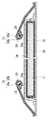
図1に本発明の一実施形態に係るおむつの一例の外観において、正面側から見た斜視図を示す。本実施形態に係るおむつ10は、展開型使い捨ておむつであり、前身頃領域10Fと、後身頃領域10Rと、これら前身頃領域10Fおよび後身頃領域10Rをつなぐ股下領域10Cとを有する。また、着用時に前身頃領域10Fと後身頃領域10Rとで着用者のウエストの部分を取り囲むウエスト周り開口部10Wが形成されている。同様に、前身頃領域10Fおよび後身頃領域10Rの下端部と股下領域10Cとで着用者の両脚の太股部分を取り囲む左右一対の脚周り開口部10Lが形成されている。<Configuration>
FIG. 1 is a perspective view of an example of a diaper according to an embodiment of the present invention, viewed from the front side. The
着用時に前身頃領域10Fは、着用者の腹側に位置し、後身頃領域10Rは着用者の背側に位置する。そして、着用時に股下領域10Cは、着用者の股下を覆い、左右一対の脚周り開口部10Lに、着用者の脚がそれぞれ通された形となる。したがって、脚周り開口部10Lは、着用者の両脚の付け根から太股あたりのいずれかに位置することとなる。 When worn, the
仮想線Pは、おむつ中央部において腹側から背側に向かって、股下部分を通って延びるものである。具体的には、仮想線Pは、例えば、おむつのウエスト側を上、股下側を下として定義すると、おむつ表面に沿って、かつ上下方向に延びると共に、股下部分を経由して、背側においても上下方向に延びるものである。 The imaginary line P extends through the crotch part from the abdomen side to the back side in the central part of the diaper. Specifically, for example, if the imaginary line P is defined with the waist side of the diaper as the upper side and the crotch side as the lower side, the phantom line P extends along the diaper surface and in the vertical direction, and passes through the crotch part on the back side. Also extends in the vertical direction.
おむつ10の外側に位置するカバーシート11の後身頃領域10Rの左右両端縁部には、着用時に前身頃領域10Fの左右両端縁部に重ね合わせてこれらをつなぎ、脚周り開口部10Lを形成し得る左右一対のファスニングテープ10Aが接着されている。このファスニングテープ10Aは、前身頃領域10Fのカバーシート11上に接着されたフロントパッチシート10Bに対して繰り返し剥離可能に接合される。 The left and right end edges of the
図2は、図1に示すおむつ10の模式的な分解斜視図であり、図3は、本発明の一実施形態に係る、伸張状態のおむつ10をトップシート14側から見た平面図である。図3のおむつ10については、説明の便宜上、部分的に破断した状態を示している。 FIG. 2 is a schematic exploded perspective view of the
図2に示すように、本実施形態におけるおむつ10は、外側から順に、良好な手触りを得るために不織布にて形成されるカバーシート11と、液不透過性を有するバックシート(裏面シート)12と、吸収体13と、液透過性を有するトップシート(表面シート)14と、疎水性(または液不透過性)のシート部材で構成された一対の立体ギャザー(サイドシート)15とを重ねた積層構造を有しているものである。図2の吸収体13については、説明の便宜上、部分的に破断した状態を示している。カバーシート11の股下領域10Cの左右両側には、それぞれ脚周り開口部10Lとなる一対の切欠き部11Nが形成されている。 As shown in FIG. 2, the
バックシート12は、カバーシート11に接着され、吸収体13は、このバックシート12とトップシート14との間に配され、この吸収体13を介してトップシート14がバックシート12に接合される。立体ギャザー15の外側部分(図3中、左右両側)は、カバーシート11の左右両側に重ね合わされ、バックシート12およびトップシート14の左右両側縁部と、カバーシート11とに対してそれぞれ一体的に接合される。また、本実施形態においては、トップシート14の左右両側に覆い重なる左右一対の立体ギャザー15の内側部分(図3中、中央側)がトップシート14に対して非接合状態となっている。 The
また、バックシート12のうち、後身頃領域10Rの上端部に対応する領域には、カバーシート11の幅方向に沿って延在し、着用者に対してウエスト周りに適度な着用感を与えるための弾性シート10Dが接合されている。カバーシート11と一対の立体ギャザー15との間には、脚周りギャザーを形成するための一対の弾性部材16がそれぞれ伸張状態で接着されている。 Moreover, in the area | region corresponding to the upper end part of back body area |
トップシート14の下に位置する本実施形態の吸収体13は、主にパルプと高吸水性樹脂(Super Absorbent Polymer、以下「SAP」とも言う)とからなる吸収性本体17を、ティシュや不織布等で構成されるコアラップなどの被覆部材18によって包んだものである。本実施形態では、吸収性本体17を被覆部材18により包むことで形成される継ぎ目は、図2に示すように、吸収体13の上面であって長手方向に延びるように形成されるが、これに限られず、本発明では、例えば、吸収体13の下面に形成されてもよい。本実施形態の吸収体13は、前身頃、股下、後身頃に亘るように、細長い形状をしている。ここで、前身頃部分から後身頃部分を前後(上下)方向とし、それに直交する方向を左右方向とすると、本実施形態の吸収体13は、前後(上下)左右の長さが異なる矩形のものである(図2では、前後(上下)の長さが左右の長さより長くなっている)。なお、本実施形態の吸収体13の形状はこれに限らず、例えば、前後(上下)左右の長さが同程度の略正方形のもの、前後(上下)端の角が丸く落とされているもの、前後(上下)に延びる楕円形のもの、円形のものなど、さまざまな形状を含む。また、吸収体13の股下部分には、一対の脚周り開口部10Lに対応するように、円弧状をなす一対の切欠き部が形成されても良い。 The
一対の立体ギャザー15は、上述したように疎水性(または液不透過性)のシート部材により構成され、本実施形態では、1枚の当該シート部材を変形(例えば、分岐や折り返し)することによってそれぞれ形成される(後述する図4を参照)。一対の立体ギャザー15は、図3に示すように、吸収体13の長手方向に沿って設けられている。本実施形態では、立体ギャザー15において、吸収体13の長手方向に延びる両側縁部のうち、一方の側縁部は略直線形状を呈し、他方の側縁部には、股下付近に切欠き部15Nが形成されている。上述のように、一対の立体ギャザー15の内側部分がトップシート14に対して非接合状態となっており、立体ギャザー15は、その略直線形状の側縁部に自由端を含む。 As described above, the pair of three-
立体ギャザー15の自由端側には、図3に示すように、引っ張り力を作用する弾性部材(例えば、糸ゴム)19が吸収体13の長手方向に沿って伸張状態で配置されている。弾性部材19は、立体ギャザー15のシート部材で挟まれている。一対の立体ギャザー15は、この弾性部材19により、着用状態において吸収体13の両側縁部に沿って起立可能となる。また、本実施形態では、立体ギャザー15は、その自由端側が相互に分岐して形成される第1の先端縁部15aおよび第2の先端縁部15bを有する。第1の先端縁部15aおよび第2の先端縁部15bの詳細については図4から図6を用いて後述する。 On the free end side of the three-dimensional gather 15, as shown in FIG. 3, an elastic member (for example, a rubber thread) 19 that acts on a tensile force is disposed in an extended state along the longitudinal direction of the
<相互に分岐して形成される2つの先端縁部>
図4および図5は本発明の一実施形態に係る、立体ギャザー15の模式的な断面図であり、図4は図3におけるIV−IV線断面図、図5は図3におけるV−V線断面図をそれぞれ示す。また、図6は、第1の接着部21aを介して接着する前の第1の先端縁部15aおよび第2の先端縁部15bを垂直に起立させたときの長さの相互関係について説明するための図であり、図4中の左側の断面形状に対応するものである。尚、説明の簡略化のため、図4ではカバーシート11および被覆部材18の継ぎ目の記載を省略しており、図5ではカバーシート11およびフロントパッチシート10Bの記載を省略している。<Two edge edges formed by branching each other>
4 and 5 are schematic cross-sectional views of the three-dimensional gather 15, according to one embodiment of the present invention. FIG. 4 is a cross-sectional view taken along line IV-IV in FIG. 3, and FIG. Cross-sectional views are shown respectively. Moreover, FIG. 6 demonstrates the mutual relationship of the length when the 1st front-end |
立体ギャザー15の自由端は、図4に示すように、第1の先端縁部15aと第2の先端縁部15bとに分岐している。第2の先端縁部15bは、吸収体13側からみて第1の先端縁部15aより外側に分岐しており、第1の先端縁部15aより長い。第1の先端縁部15aおよび第2の先端縁部15bは、吸収体13の長手方向に沿ってそれぞれ延びている。第1の先端縁部15aには、弾性部材19が当該長手方向に沿って配置される。弾性部材19は、第1の先端縁部15aのシート部材で挟まれている。一方、第2の先端縁部15bのうち少なくとも着用者の肌に接触可能な部位には、弾性部材が配置されていない。第1の先端縁部15aおよび第2の先端縁部15bは、第1の先端縁部15aのうち弾性部材19を挟んだ部分と着用者の肌とで、第2の先端縁部15bを挟むようにそれぞれ構成されている。 As shown in FIG. 4, the free end of the three-dimensional gather 15 is branched into a
本実施形態では、第2の先端縁部15bには、第2の先端縁部15bを折り返す折り返し部20が設けられる。折り返し部20は、図4に示すように、第1の先端縁部15aのうち弾性部材19を挟んだ部分を第2の先端縁部15bで挟むように構成される。 In the present embodiment, the second
また、立体ギャザー15には、第2の先端縁部15bと立体ギャザー15とが重ねる部分の少なくとも一部を接着する第1の接着部21aが設けられる。ここで「接着」は、例えば、ヒートエンボス加工、超音波、接着剤の使用やホットメルトのいずれか一つ、また、これらを組み合わせることによって行われることが可能である。また、「少なくとも一部を接着」とは、例えば、当該重ねる部分の半分または全域を接着したり、吸収体13の長手方向に亘って当該重ねる部分を間欠的に接着したりすることを表す。本実施形態では、第2の先端縁部15bは、図4に示すように、第1の先端縁部15aのうち弾性部材19を挟んだ部分を包むように、第1の先端縁部15aの先端付近に第1の接着部21aを介して接着されている。 The three-dimensional gather 15 is provided with a
従来、弾性部材が配される立体ギャザーの先端部による肌の締め付けに対し、立体ギャザーの先端を延出させて延出部分を形成することで、その締め付けの低減を図ったものが知られている。しかしながら、その延出部分は、着用者の動きに伴いそれぞれ異なる方向に移動する結果、着用者の肌に対して一定の位置を維持することが出来ない結果、フィット感が悪化し、立体ギャザーとして機能しない場合があった。 Conventionally, it is known that the tightening of the skin by tightening the tip of the three-dimensional gather where the elastic member is arranged is intended to reduce the tightening by extending the tip of the three-dimensional gather to form an extended portion. Yes. However, the extension part moves in different directions with the movement of the wearer, and as a result, it is not possible to maintain a certain position with respect to the wearer's skin. There were cases where it did not work.
本実施形態では、第1の先端縁部15aのうち弾性部材19を挟んだ部分が、第2の先端縁部15bを介して着用者の肌にフィットするように接触することになる。そのため、立体ギャザー15の先端縁部が異なる方向に移動するということが抑止され、肌に対して立体ギャザー15の先端部が一定の位置を維持しうる。よって、フィット感を向上させることが可能となり、また、弾性部材19が複数のシート部材によって覆われるため、着用者の肌に対する締め付けを低減することが可能となる。 In this embodiment, the part which pinched | interposed the
本実施形態では、第1の接着部21aにより、第1の先端縁部15aおよび第2の先端縁部15bが一体化し、弾性部材19が複数のシート部材によって覆われた状態で立体ギャザー15の先端部が一塊となる。よって、着用者の肌に一塊のシート部材が接する結果、肌に対して立体ギャザー15の先端部が一定の位置をさらに維持することができるため、フィット感を一層向上させることが可能となる。また、この一塊のシート部材が吸収体13に対して内側を向いたとき、液体に対する堰き止めとしても機能するため、本実施形態の構成により、防漏性を強化することも可能となる。なお、第1の接着部21aが当該重ねる部分の全域を接着した場合、第1の先端縁部15aと第2の先端縁部15bとがさらに一体化されるため、フィット感および防漏性をさらに向上させることが可能になる。 In the present embodiment, the
図5に移り、本実施形態では、立体ギャザー15の先端部は、トップシート14に対して接着されている。本実施形態では、第2の先端縁部15bの先端部が、トップシート14に対し第2の接着部21bを介して接着される。すなわち、おむつ10は、立体ギャザー15の吸収体13の長手方向の端部において、一対の立体ギャザー15の対向する面(第2の先端縁部15bの先端部の面)と、トップシート14と、を接着する第2の接着部21bを有している。 Turning to FIG. 5, in the present embodiment, the tip of the three-dimensional gather 15 is bonded to the
第2の接着部21bにより、着用状態で、図4に示すような立体ギャザー15の起立可能な領域において、一体となった第1の先端縁部15aおよび第2の先端縁部15bが吸収体側に向くように付勢されるため、防漏性を強化するという効果が安定して発揮されることになる。また、第2の接着部21bを設けない態様よりも、肌に対して立体ギャザー15の先端部が一定の位置を維持することができるため、フィット感を向上させることが可能となる。 The
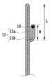
図6に示すように、吸収体13の長手方向に直交する断面において、第1の先端縁部15aと第2の先端縁部15bとが分岐する分岐点から第2の先端縁部15bの先端までの距離Lは、当該分岐点から第1の先端縁部15aの先端までの距離Mよりも長いものとなっている。本発明者は、L:M=1:nの関係式が成立するとき、数値nが約0.40以上約0.85以下であることが、本発明の効果を発揮する上で好ましいことを発見した。 As shown in FIG. 6, in the cross section orthogonal to the longitudinal direction of the
<変形例>
本発明は、上述した実施形態に限られることなく、本発明の技術的思想から逸脱しない範囲で、適宜の変更や変形が可能である。<Modification>
The present invention is not limited to the above-described embodiment, and appropriate changes and modifications can be made without departing from the technical idea of the present invention.
例えば、上記実施形態に係るおむつの構造は、上述したような展開型に限定されるわけではなく、特許請求の範囲に規定された吸収性物品の構成を含むおむつでありさえすれば、どのような構成であってもよい。例えば、パンツ型の使い捨ておむつや、尿パッドなどであっても本発明を適用可能である。 For example, the structure of the diaper according to the above-described embodiment is not limited to the unfolded type as described above, and as long as it is a diaper including the configuration of the absorbent article as defined in the claims, It may be a simple configuration. For example, the present invention can be applied to a pants-type disposable diaper or a urine pad.
加えて、上記実施形態では、弾性部材19は、立体ギャザー15が接着される領域において配置されていないがこの限りではなく、本発明では、例えば、当該領域において第1の先端縁部15aに弾性部材19を配置してもよい。また、第1の先端縁部15aに配置する弾性部材19の数を2以上としてもよい。 In addition, in the above embodiment, the
さらに、上記実施形態では、第1の先端縁部15aのみに弾性部材19が配置されているがこの限りではなく、本発明では、第2の先端縁部15bにおいても、シート部材で挟まれるように、吸収体13の長手方向に沿って配置される弾性部材をさらに有してもよい。この場合、上述したように、少なくとも着用者の肌に接触可能な部位には、弾性部材が配置されないようにする。この構成により、第1の先端縁部15aの先端部に配置された弾性部材19と、第2の先端縁部15bの先端部に配置された弾性部材と、が一体となって肌に接触したときに、肌に対する接触面積を広げることが可能となるため、肌に対する締め付けを低減することが可能となる。 Furthermore, in the above embodiment, the
また、上記実施形態では、図4に示した立体ギャザー15の形状に限られず、本発明では、以下のような変形例も含みうる。 Moreover, in the said embodiment, it is not restricted to the shape of the solid gathers 15 shown in FIG. 4, In the present invention, the following modifications may be included.
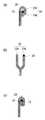
図7は、立体ギャザー15の断面形状の例を示す図であり、図4中の左側の断面形状に対応するものである。図7(a)は立体ギャザー15の自由端側を分岐させ且つ折り返したもの、図7(b)は立体ギャザー15の自由端側を分岐させたもの、図7(c)は立体ギャザー15の自由端側を折り返して巻き込んだものをそれぞれ表す。図7(a)は上記実施形態と同様の形状である。 FIG. 7 is a diagram illustrating an example of a cross-sectional shape of the three-dimensional gather 15, and corresponds to the cross-sectional shape on the left side in FIG. FIG. 7A is a diagram in which the free end side of the three-dimensional gather 15 is branched and folded, FIG. 7B is a diagram in which the free end side of the three-dimensional gather 15 is branched, and FIG. Represents the wrapping around the free end. FIG. 7A shows the same shape as in the above embodiment.
上記実施形態、つまり、図7(a)に示す立体ギャザー15では、第1の先端縁部15aより第2の先端縁部15bの方が長く、第2の先端縁部15bに折り返し部20が設けられているが、図7(b)に示すように、第1の先端縁部15aと第2の先端縁部15bとの長さが略等しく、立体ギャザー15に折り返し部20を設けないものであってもよい。要は、第1の先端縁部15aおよび第2の先端縁部15bが、第1の先端縁部15aのうち弾性部材19を挟んだ部分と着用者の肌とで、第2の先端縁部15bを挟むようにそれぞれ構成されればよい。なお、当該変形例では、第1の先端縁部15aと第2の先端縁部15bとが対向する面を接着してもよい。これにより、第1の先端縁部15aと第2の先端縁部15bとが一体化されるため、上記実施形態と同様に、フィット感を向上させることが可能になる。 In the above-described embodiment, that is, the three-dimensional gather 15 shown in FIG. 7A, the
また、上記実施形態では、立体ギャザー15の自由端側が分岐しているが、図7(c)に示すように、立体ギャザー15の自由端側を分岐させず、折り返して巻き込む態様であってもよい。この変形例では、折り返し部20は、立体ギャザー15のうち弾性部材19を挟んだ部分と着用者の肌とでシート部材を挟むように、且つ、挟んだ部分をシート部材でさらに挟むように、立体ギャザー15の自由端側を折り返す。この態様により、立体ギャザー15のうち弾性部材19を挟んだ部分がシート部材によって包まれるので、上記実施形態と同様に、吸収性物品のフィット感を保持しつつ、着用者の肌に対する締め付けを低減することが可能となる。また、この立体ギャザー15の先端部が吸収体13に対して内側を向いたとき、上記実施形態と同様に、防漏性を強化することも可能となる。なお、当該変形例では、立体ギャザー15の自由端側のうち立体ギャザー15を折り返したときに重なる部分の少なくとも一部を接着する第1の接着部21aをさらに有してもいい。 Moreover, in the said embodiment, although the free end side of the three-dimensional gather 15 has branched, as shown in FIG.7 (c), even if it is an aspect which folds back and winds, without branching the free end side of the three-dimensional gather 15 Good. In this modified example, the folded
本発明では、立体ギャザーは、勿論、上述した形状に限られるものではなく、種々の形状を採用することが可能である。例えば、立体ギャザー15の自由端側を分岐する数を3以上にしたり、上述した各形状を組み合わせたりしてもよい。また、立体ギャザー15の先端部の向きを逆にする、つまり、図7(a)を例に挙げると、第1の先端縁部15aを吸収体13から見て第2の先端縁部15bより外側に分岐させてもよい。 In the present invention, the three-dimensional gathering is of course not limited to the shape described above, and various shapes can be adopted. For example, the number of branches on the free end side of the three-dimensional gather 15 may be three or more, or the shapes described above may be combined. Further, the direction of the front end portion of the three-dimensional gather 15 is reversed, that is, taking FIG. 7A as an example, the first front
10 おむつ
10A ファスニングテープ
10B フロントパッチシート
10F 前身頃領域
10R 後身頃領域
10C 股下領域
10W ウエスト周り開口部
10L 脚周り開口部
11 カバーシート
11N、15N 切欠き部
12 バックシート
13 吸収体
14 トップシート
15 立体ギャザー
15a 第1の先端縁部
15b 第2の先端縁部
16、19 弾性部材
17 吸収性本体
18 被覆部材
20 折り返し部
21a 第1の接着部
21b 第2の接着部DESCRIPTION OF
Claims (6)
Translated fromJapanese前記立体ギャザーの自由端側が相互に分岐して形成される第1の先端縁部および第2の先端縁部と、
前記第1の先端縁部において前記シート部材で挟まれるように、前記長手方向に沿って配置される弾性部材と、を有し、
前記第2の先端縁部のうち少なくとも着用者の肌に接触可能な部位には弾性部材が配置されず、
前記第1の先端縁部および前記第2の先端縁部は、前記第1の先端縁部のうち前記弾性部材を挟んだ部分と前記肌とで、前記第2の先端縁部を挟むようにそれぞれ構成されており、
前記第2の先端縁部において前記シート部材で挟まれるように、前記長手方向に沿って配置される弾性部材をさらに有することを特徴とする吸収性物品。A liquid-impermeable back sheet, a liquid-permeable top sheet joined to the back sheet, an absorber disposed between the back sheet and the top sheet, and a sheet member, the absorber A pair of three-dimensional gathers provided along the longitudinal direction of the absorbent article,
A first tip edge and a second tip edge formed by branching the free end sides of the three-dimensional gather;
An elastic member disposed along the longitudinal direction so as to be sandwiched between the sheet members at the first tip edge portion,
An elastic member is not disposed in a portion that can contact at least the wearer's skin among the second tip edge portion,
The first tip edge portion and the second tip edge portion sandwich the second tip edge portion between the portion of the first tip edge portion sandwiching the elastic member and the skin. Each is composed,
Wherein as sandwiched by the sheet member at a second distal edge, the absorbent article whichfurther Yusuke characterized Rukotoan elastic member disposed along the longitudinal direction.
Priority Applications (1)
| Application Number | Priority Date | Filing Date | Title |
|---|---|---|---|
| JP2016039337AJP6586906B2 (en) | 2016-03-01 | 2016-03-01 | Absorbent articles |
Applications Claiming Priority (1)
| Application Number | Priority Date | Filing Date | Title |
|---|---|---|---|
| JP2016039337AJP6586906B2 (en) | 2016-03-01 | 2016-03-01 | Absorbent articles |
Publications (2)
| Publication Number | Publication Date |
|---|---|
| JP2017153697A JP2017153697A (en) | 2017-09-07 |
| JP6586906B2true JP6586906B2 (en) | 2019-10-09 |
Family
ID=59808863
Family Applications (1)
| Application Number | Title | Priority Date | Filing Date |
|---|---|---|---|
| JP2016039337AExpired - Fee RelatedJP6586906B2 (en) | 2016-03-01 | 2016-03-01 | Absorbent articles |
Country Status (1)
| Country | Link |
|---|---|
| JP (1) | JP6586906B2 (en) |
Family Cites Families (6)
| Publication number | Priority date | Publication date | Assignee | Title |
|---|---|---|---|---|
| JPH0286519U (en)* | 1988-12-22 | 1990-07-09 | ||
| PH31459A (en)* | 1992-11-30 | 1998-11-03 | Procter & Gamble | Absorbent article having elasticized side flaps and wings. |
| JPH1128224A (en)* | 1998-06-08 | 1999-02-02 | Shiseido Co Ltd | Manufacture of absorbent article |
| SE517430C2 (en)* | 2000-10-19 | 2002-06-04 | Sca Hygiene Prod Ab | Absorbent articles with double leakage barriers and simple elastic system |
| JP5091064B2 (en)* | 2008-09-05 | 2012-12-05 | 王子ネピア株式会社 | Absorbent articles |
| JP2012249942A (en)* | 2011-06-06 | 2012-12-20 | Livedo Corporation | Absorbent article |
- 2016
- 2016-03-01JPJP2016039337Apatent/JP6586906B2/ennot_activeExpired - Fee Related
Also Published As
| Publication number | Publication date |
|---|---|
| JP2017153697A (en) | 2017-09-07 |
Similar Documents
| Publication | Publication Date | Title |
|---|---|---|
| JP6232471B1 (en) | Absorbent articles | |
| JP5577085B2 (en) | Pants-type disposable diapers | |
| CN103826588A (en) | Disposable wearing article | |
| WO2013132982A1 (en) | Disposable wearing article | |
| JP5558617B1 (en) | Absorbent pad | |
| JP2013220225A (en) | Absorbent article | |
| WO2014199784A1 (en) | Disposable pull-on diaper | |
| JP5942040B1 (en) | Disposable diapers | |
| JP2016120142A (en) | Disposable wearing items | |
| JP6297437B2 (en) | Disposable wear | |
| JP2016112165A (en) | Disposable wearing article | |
| JP6112981B2 (en) | Absorbent articles | |
| JP2014128551A (en) | Absorbent pad | |
| CN112545770A (en) | Underpants-type absorbent article comfortable to wear | |
| JP6297438B2 (en) | Disposable wear | |
| JP2019068949A (en) | Absorbent article | |
| JP2015073636A5 (en) | ||
| JP6414107B2 (en) | Absorbent articles | |
| JP2018202046A (en) | Absorbent articles | |
| JP6586906B2 (en) | Absorbent articles | |
| JP6255203B2 (en) | Absorbent articles | |
| CN215273908U (en) | Underpants-type absorbent article comfortable to wear | |
| JP2019165888A (en) | Absorbent article | |
| WO2014084087A1 (en) | Absorptive pad | |
| WO2021054392A1 (en) | Absorbent article |
Legal Events
| Date | Code | Title | Description |
|---|---|---|---|
| A621 | Written request for application examination | Free format text:JAPANESE INTERMEDIATE CODE: A621 Effective date:20180514 | |
| A977 | Report on retrieval | Free format text:JAPANESE INTERMEDIATE CODE: A971007 Effective date:20190208 | |
| A131 | Notification of reasons for refusal | Free format text:JAPANESE INTERMEDIATE CODE: A131 Effective date:20190312 | |
| A521 | Request for written amendment filed | Free format text:JAPANESE INTERMEDIATE CODE: A523 Effective date:20190425 | |
| TRDD | Decision of grant or rejection written | ||
| A01 | Written decision to grant a patent or to grant a registration (utility model) | Free format text:JAPANESE INTERMEDIATE CODE: A01 Effective date:20190813 | |
| A61 | First payment of annual fees (during grant procedure) | Free format text:JAPANESE INTERMEDIATE CODE: A61 Effective date:20190826 | |
| R150 | Certificate of patent or registration of utility model | Ref document number:6586906 Country of ref document:JP Free format text:JAPANESE INTERMEDIATE CODE: R150 | |
| R250 | Receipt of annual fees | Free format text:JAPANESE INTERMEDIATE CODE: R250 | |
| R250 | Receipt of annual fees | Free format text:JAPANESE INTERMEDIATE CODE: R250 | |
| LAPS | Cancellation because of no payment of annual fees |