JP6585104B2 - Inductive power transfer system - Google Patents
Inductive power transfer systemDownload PDFInfo
- Publication number
- JP6585104B2 JP6585104B2JP2017010860AJP2017010860AJP6585104B2JP 6585104 B2JP6585104 B2JP 6585104B2JP 2017010860 AJP2017010860 AJP 2017010860AJP 2017010860 AJP2017010860 AJP 2017010860AJP 6585104 B2JP6585104 B2JP 6585104B2
- Authority
- JP
- Japan
- Prior art keywords
- coil
- power supply
- magnetic flux
- power
- pad
- Prior art date
- Legal status (The legal status is an assumption and is not a legal conclusion. Google has not performed a legal analysis and makes no representation as to the accuracy of the status listed.)
- Active
Links
Images


Classifications
- H—ELECTRICITY
- H01—ELECTRIC ELEMENTS
- H01F—MAGNETS; INDUCTANCES; TRANSFORMERS; SELECTION OF MATERIALS FOR THEIR MAGNETIC PROPERTIES
- H01F38/00—Adaptations of transformers or inductances for specific applications or functions
- H01F38/14—Inductive couplings
- B—PERFORMING OPERATIONS; TRANSPORTING
- B60—VEHICLES IN GENERAL
- B60L—PROPULSION OF ELECTRICALLY-PROPELLED VEHICLES; SUPPLYING ELECTRIC POWER FOR AUXILIARY EQUIPMENT OF ELECTRICALLY-PROPELLED VEHICLES; ELECTRODYNAMIC BRAKE SYSTEMS FOR VEHICLES IN GENERAL; MAGNETIC SUSPENSION OR LEVITATION FOR VEHICLES; MONITORING OPERATING VARIABLES OF ELECTRICALLY-PROPELLED VEHICLES; ELECTRIC SAFETY DEVICES FOR ELECTRICALLY-PROPELLED VEHICLES
- B60L5/00—Current collectors for power supply lines of electrically-propelled vehicles
- B60L5/005—Current collectors for power supply lines of electrically-propelled vehicles without mechanical contact between the collector and the power supply line
- B—PERFORMING OPERATIONS; TRANSPORTING
- B60—VEHICLES IN GENERAL
- B60L—PROPULSION OF ELECTRICALLY-PROPELLED VEHICLES; SUPPLYING ELECTRIC POWER FOR AUXILIARY EQUIPMENT OF ELECTRICALLY-PROPELLED VEHICLES; ELECTRODYNAMIC BRAKE SYSTEMS FOR VEHICLES IN GENERAL; MAGNETIC SUSPENSION OR LEVITATION FOR VEHICLES; MONITORING OPERATING VARIABLES OF ELECTRICALLY-PROPELLED VEHICLES; ELECTRIC SAFETY DEVICES FOR ELECTRICALLY-PROPELLED VEHICLES
- B60L53/00—Methods of charging batteries, specially adapted for electric vehicles; Charging stations or on-board charging equipment therefor; Exchange of energy storage elements in electric vehicles
- B60L53/10—Methods of charging batteries, specially adapted for electric vehicles; Charging stations or on-board charging equipment therefor; Exchange of energy storage elements in electric vehicles characterised by the energy transfer between the charging station and the vehicle
- B60L53/12—Inductive energy transfer
- B60L53/122—Circuits or methods for driving the primary coil, e.g. supplying electric power to the coil
- B—PERFORMING OPERATIONS; TRANSPORTING
- B60—VEHICLES IN GENERAL
- B60L—PROPULSION OF ELECTRICALLY-PROPELLED VEHICLES; SUPPLYING ELECTRIC POWER FOR AUXILIARY EQUIPMENT OF ELECTRICALLY-PROPELLED VEHICLES; ELECTRODYNAMIC BRAKE SYSTEMS FOR VEHICLES IN GENERAL; MAGNETIC SUSPENSION OR LEVITATION FOR VEHICLES; MONITORING OPERATING VARIABLES OF ELECTRICALLY-PROPELLED VEHICLES; ELECTRIC SAFETY DEVICES FOR ELECTRICALLY-PROPELLED VEHICLES
- B60L53/00—Methods of charging batteries, specially adapted for electric vehicles; Charging stations or on-board charging equipment therefor; Exchange of energy storage elements in electric vehicles
- B60L53/10—Methods of charging batteries, specially adapted for electric vehicles; Charging stations or on-board charging equipment therefor; Exchange of energy storage elements in electric vehicles characterised by the energy transfer between the charging station and the vehicle
- B60L53/12—Inductive energy transfer
- B60L53/126—Methods for pairing a vehicle and a charging station, e.g. establishing a one-to-one relation between a wireless power transmitter and a wireless power receiver
- H—ELECTRICITY
- H01—ELECTRIC ELEMENTS
- H01F—MAGNETS; INDUCTANCES; TRANSFORMERS; SELECTION OF MATERIALS FOR THEIR MAGNETIC PROPERTIES
- H01F27/00—Details of transformers or inductances, in general
- H01F27/28—Coils; Windings; Conductive connections
- H01F27/288—Shielding
- H01F27/2885—Shielding with shields or electrodes
- H—ELECTRICITY
- H01—ELECTRIC ELEMENTS
- H01F—MAGNETS; INDUCTANCES; TRANSFORMERS; SELECTION OF MATERIALS FOR THEIR MAGNETIC PROPERTIES
- H01F27/00—Details of transformers or inductances, in general
- H01F27/34—Special means for preventing or reducing unwanted electric or magnetic effects, e.g. no-load losses, reactive currents, harmonics, oscillations, leakage fields
- H01F27/346—Preventing or reducing leakage fields
- H—ELECTRICITY
- H01—ELECTRIC ELEMENTS
- H01F—MAGNETS; INDUCTANCES; TRANSFORMERS; SELECTION OF MATERIALS FOR THEIR MAGNETIC PROPERTIES
- H01F41/00—Apparatus or processes specially adapted for manufacturing or assembling magnets, inductances or transformers; Apparatus or processes specially adapted for manufacturing materials characterised by their magnetic properties
- H01F41/02—Apparatus or processes specially adapted for manufacturing or assembling magnets, inductances or transformers; Apparatus or processes specially adapted for manufacturing materials characterised by their magnetic properties for manufacturing cores, coils, or magnets
- H01F41/04—Apparatus or processes specially adapted for manufacturing or assembling magnets, inductances or transformers; Apparatus or processes specially adapted for manufacturing materials characterised by their magnetic properties for manufacturing cores, coils, or magnets for manufacturing coils
- B—PERFORMING OPERATIONS; TRANSPORTING
- B60—VEHICLES IN GENERAL
- B60L—PROPULSION OF ELECTRICALLY-PROPELLED VEHICLES; SUPPLYING ELECTRIC POWER FOR AUXILIARY EQUIPMENT OF ELECTRICALLY-PROPELLED VEHICLES; ELECTRODYNAMIC BRAKE SYSTEMS FOR VEHICLES IN GENERAL; MAGNETIC SUSPENSION OR LEVITATION FOR VEHICLES; MONITORING OPERATING VARIABLES OF ELECTRICALLY-PROPELLED VEHICLES; ELECTRIC SAFETY DEVICES FOR ELECTRICALLY-PROPELLED VEHICLES
- B60L2200/00—Type of vehicles
- B60L2200/26—Rail vehicles
- H—ELECTRICITY
- H02—GENERATION; CONVERSION OR DISTRIBUTION OF ELECTRIC POWER
- H02J—CIRCUIT ARRANGEMENTS OR SYSTEMS FOR SUPPLYING OR DISTRIBUTING ELECTRIC POWER; SYSTEMS FOR STORING ELECTRIC ENERGY
- H02J50/00—Circuit arrangements or systems for wireless supply or distribution of electric power
- H02J50/005—Mechanical details of housing or structure aiming to accommodate the power transfer means, e.g. mechanical integration of coils, antennas or transducers into emitting or receiving devices
- H—ELECTRICITY
- H02—GENERATION; CONVERSION OR DISTRIBUTION OF ELECTRIC POWER
- H02J—CIRCUIT ARRANGEMENTS OR SYSTEMS FOR SUPPLYING OR DISTRIBUTING ELECTRIC POWER; SYSTEMS FOR STORING ELECTRIC ENERGY
- H02J50/00—Circuit arrangements or systems for wireless supply or distribution of electric power
- H02J50/10—Circuit arrangements or systems for wireless supply or distribution of electric power using inductive coupling
- H02J50/12—Circuit arrangements or systems for wireless supply or distribution of electric power using inductive coupling of the resonant type
- H—ELECTRICITY
- H02—GENERATION; CONVERSION OR DISTRIBUTION OF ELECTRIC POWER
- H02J—CIRCUIT ARRANGEMENTS OR SYSTEMS FOR SUPPLYING OR DISTRIBUTING ELECTRIC POWER; SYSTEMS FOR STORING ELECTRIC ENERGY
- H02J50/00—Circuit arrangements or systems for wireless supply or distribution of electric power
- H02J50/40—Circuit arrangements or systems for wireless supply or distribution of electric power using two or more transmitting or receiving devices
- H02J50/402—Circuit arrangements or systems for wireless supply or distribution of electric power using two or more transmitting or receiving devices the two or more transmitting or the two or more receiving devices being integrated in the same unit, e.g. power mats with several coils or antennas with several sub-antennas
- H—ELECTRICITY
- H02—GENERATION; CONVERSION OR DISTRIBUTION OF ELECTRIC POWER
- H02J—CIRCUIT ARRANGEMENTS OR SYSTEMS FOR SUPPLYING OR DISTRIBUTING ELECTRIC POWER; SYSTEMS FOR STORING ELECTRIC ENERGY
- H02J50/00—Circuit arrangements or systems for wireless supply or distribution of electric power
- H02J50/70—Circuit arrangements or systems for wireless supply or distribution of electric power involving the reduction of electric, magnetic or electromagnetic leakage fields
- H—ELECTRICITY
- H02—GENERATION; CONVERSION OR DISTRIBUTION OF ELECTRIC POWER
- H02J—CIRCUIT ARRANGEMENTS OR SYSTEMS FOR SUPPLYING OR DISTRIBUTING ELECTRIC POWER; SYSTEMS FOR STORING ELECTRIC ENERGY
- H02J50/00—Circuit arrangements or systems for wireless supply or distribution of electric power
- H02J50/80—Circuit arrangements or systems for wireless supply or distribution of electric power involving the exchange of data, concerning supply or distribution of electric power, between transmitting devices and receiving devices
- H—ELECTRICITY
- H02—GENERATION; CONVERSION OR DISTRIBUTION OF ELECTRIC POWER
- H02J—CIRCUIT ARRANGEMENTS OR SYSTEMS FOR SUPPLYING OR DISTRIBUTING ELECTRIC POWER; SYSTEMS FOR STORING ELECTRIC ENERGY
- H02J50/00—Circuit arrangements or systems for wireless supply or distribution of electric power
- H02J50/90—Circuit arrangements or systems for wireless supply or distribution of electric power involving detection or optimisation of position, e.g. alignment
- Y—GENERAL TAGGING OF NEW TECHNOLOGICAL DEVELOPMENTS; GENERAL TAGGING OF CROSS-SECTIONAL TECHNOLOGIES SPANNING OVER SEVERAL SECTIONS OF THE IPC; TECHNICAL SUBJECTS COVERED BY FORMER USPC CROSS-REFERENCE ART COLLECTIONS [XRACs] AND DIGESTS
- Y02—TECHNOLOGIES OR APPLICATIONS FOR MITIGATION OR ADAPTATION AGAINST CLIMATE CHANGE
- Y02T—CLIMATE CHANGE MITIGATION TECHNOLOGIES RELATED TO TRANSPORTATION
- Y02T10/00—Road transport of goods or passengers
- Y02T10/60—Other road transportation technologies with climate change mitigation effect
- Y02T10/70—Energy storage systems for electromobility, e.g. batteries
- Y—GENERAL TAGGING OF NEW TECHNOLOGICAL DEVELOPMENTS; GENERAL TAGGING OF CROSS-SECTIONAL TECHNOLOGIES SPANNING OVER SEVERAL SECTIONS OF THE IPC; TECHNICAL SUBJECTS COVERED BY FORMER USPC CROSS-REFERENCE ART COLLECTIONS [XRACs] AND DIGESTS
- Y02—TECHNOLOGIES OR APPLICATIONS FOR MITIGATION OR ADAPTATION AGAINST CLIMATE CHANGE
- Y02T—CLIMATE CHANGE MITIGATION TECHNOLOGIES RELATED TO TRANSPORTATION
- Y02T10/00—Road transport of goods or passengers
- Y02T10/60—Other road transportation technologies with climate change mitigation effect
- Y02T10/7072—Electromobility specific charging systems or methods for batteries, ultracapacitors, supercapacitors or double-layer capacitors
- Y—GENERAL TAGGING OF NEW TECHNOLOGICAL DEVELOPMENTS; GENERAL TAGGING OF CROSS-SECTIONAL TECHNOLOGIES SPANNING OVER SEVERAL SECTIONS OF THE IPC; TECHNICAL SUBJECTS COVERED BY FORMER USPC CROSS-REFERENCE ART COLLECTIONS [XRACs] AND DIGESTS
- Y02—TECHNOLOGIES OR APPLICATIONS FOR MITIGATION OR ADAPTATION AGAINST CLIMATE CHANGE
- Y02T—CLIMATE CHANGE MITIGATION TECHNOLOGIES RELATED TO TRANSPORTATION
- Y02T90/00—Enabling technologies or technologies with a potential or indirect contribution to GHG emissions mitigation
- Y02T90/10—Technologies relating to charging of electric vehicles
- Y02T90/12—Electric charging stations
- Y—GENERAL TAGGING OF NEW TECHNOLOGICAL DEVELOPMENTS; GENERAL TAGGING OF CROSS-SECTIONAL TECHNOLOGIES SPANNING OVER SEVERAL SECTIONS OF THE IPC; TECHNICAL SUBJECTS COVERED BY FORMER USPC CROSS-REFERENCE ART COLLECTIONS [XRACs] AND DIGESTS
- Y02—TECHNOLOGIES OR APPLICATIONS FOR MITIGATION OR ADAPTATION AGAINST CLIMATE CHANGE
- Y02T—CLIMATE CHANGE MITIGATION TECHNOLOGIES RELATED TO TRANSPORTATION
- Y02T90/00—Enabling technologies or technologies with a potential or indirect contribution to GHG emissions mitigation
- Y02T90/10—Technologies relating to charging of electric vehicles
- Y02T90/14—Plug-in electric vehicles
Landscapes
- Engineering & Computer Science (AREA)
- Power Engineering (AREA)
- Transportation (AREA)
- Mechanical Engineering (AREA)
- Computer Networks & Wireless Communication (AREA)
- Manufacturing & Machinery (AREA)
- Current-Collector Devices For Electrically Propelled Vehicles (AREA)
- Electric Propulsion And Braking For Vehicles (AREA)
- Charge And Discharge Circuits For Batteries Or The Like (AREA)
- Physics & Mathematics (AREA)
- Electromagnetism (AREA)
- Near-Field Transmission Systems (AREA)
Description
Translated fromJapanese(誘導電力伝達装置)
本発明は、磁束を発生しまたは受ける装置に関するものである。本発明は、これに限らないが、特に、誘導電力伝達(IPT)を用いて電力伝達を行うパッドなどのように、外形が低く実質的に平面状であるデバイスに利用される。(Inductive power transmission device)
The present invention relates to an apparatus for generating or receiving magnetic flux. The present invention is not limited to this, but is particularly used for a device having a low profile and a substantially planar shape, such as a pad for performing power transmission using inductive power transmission (IPT).
IPTシステムと、誘導電力伝達のための1次側または2次側の巻き線からなる一つ以上の巻き線を含むパッドの使用は、国際公開公報WO2008/14033で紹介されている。その内容は、ここに参照によって組み込まれる。The use of an IPT system and a pad comprising one or more windings consisting of primary or secondary windings for inductive power transfer is introduced in WO 2008/14033. The contents of which are hereby incorporated by reference.
一つの利用形態としてのIPT電力伝達パッドは、電気自動車等電気車両への充電である。この利用形態はこのセクションにおいて本発明のひとつの利用形態の背景を提供するために論じられる。しかしながら、電気車両への充電はひとつの例であり、本発明は、誘導電力伝達全体への利用形態に及ぶものである。電気車両への充電は、たとえば、車両が静止状態であっても道路を移動中であっても行うことができる。IPT電力伝達パッドは、電力の「ピックアップ」(すなわち、IPTシステムの2次側の巻き線)として使われるとともに、電力が供給される「充電パッド」(すなわち、1次側の巻き線)として、たとえばガレージの床や道路などに固定されて使われることもある。An IPT power transmission pad as one form of use is charging an electric vehicle such as an electric vehicle. This usage is discussed in this section to provide a background for one usage of the present invention. However, charging to an electric vehicle is an example, and the present invention covers a form of use for the entire induction power transmission. Charging an electric vehicle can be performed, for example, whether the vehicle is stationary or moving on a road. The IPT power transfer pad is used as a power “pickup” (ie, secondary winding of the IPT system) and as a “charging pad” (ie, primary winding) to which power is supplied. For example, it may be fixed to a garage floor or road.
IPT道路システムの目的は、ワイヤレスで車両との物理的な接触をせずに静止または移動している車両に電力を伝達するものである。このシステムの送電部は、コイル(たとえば、前述のようなパッドなど)に電力を供給する電源やたくさんの同様のコイルを有するトラックから構成されており、このようなシステムは、通常10kHzから150kHz程度の適切な周波数で動作するように同調されている。レシーバーが車両の下面側に置かれ、車両が上方または近傍(電力を結合して送れるよう十分近く)に来た時に電力を受けられるよう1次側のトランスミッターに結合される。ピックアップレシーバーもまた、通常、コンバータに接続されたコイル(上記のパッドなど)と車載された適切な電力のレギュレータから構成される。便宜上、電力が誘導的に受けられる道路の箇所をここでは、「トラック」と呼ぶ。The purpose of the IPT road system is to transfer power wirelessly to a stationary or moving vehicle without physical contact with the vehicle. The power transmission part of this system is composed of a power supply for supplying power to coils (for example, the pads as described above) and a track having many similar coils. Such a system is usually about 10 kHz to 150 kHz. Tuned to operate at the appropriate frequency. A receiver is placed on the underside of the vehicle and is coupled to the primary transmitter so that it can receive power when the vehicle is above or near (enough enough to combine and send power). Pick-up receivers are also usually composed of a coil (such as the pad described above) connected to a converter and a suitable power regulator mounted on the vehicle. For convenience, the location on the road where power is received inductively is referred to herein as a “truck”.
トラックは道路の走行帯(レーン)中央に沿って置かれた複数のパッドにより形成される。このことにより、車両がトラックの直近を道路に沿って移動する際に、電力を車両へ実質的に連続して供給することができる。The truck is formed by a plurality of pads placed along the center of a road lane. Thus, when the vehicle moves along the road in the immediate vicinity of the truck, power can be supplied to the vehicle substantially continuously.
近年、このようなシステムは、持続的にワイヤレスで、電力を個人の輸送機関に提供することができる可能性があるため、注目を集めている。このようなシステムが有用であるためには、合理的な大きさのエアギャップ(たとえば、100−300mm)を越えて十分な電力を伝達できるだけではなく、トラックとピックアップの距離が変動しても許容し、車両をトラックに誘導する誘導装置に頼らないようにしなくてはならない。道路システムにおいては、移動中の車両に対してこのような距離変動はラテラル方向(垂直方向及び移動方向の両者に対し直角となる方向)には十分起こりうることである。充電中の静止状態の車両に対しては、適切な長手方向の変位に対し受容できるレベルの電力を伝達する能力は、駐車を簡単にできるようにするため、特別な関心事である。ピックアップパッドの電力伝達のプロフィール(分布図)は滑らかなプロフィールであることが理想である。ラテラル方向の距離に対しできる限り広い範囲で本質的に一定であって(かつ不足なく)、両端部では滑らかな低下があることが好ましい。このような電力伝達プロフィールであれば、道路システムの電子制御レギュレータ(1次側および2次側)への要求を緩和し、動作時に1次側とレシーバーパッドとの結合に無視しえない変動が生じるシステムに対して、全体的に同等の結合をするように動作性能を改善することができる。In recent years, such systems have attracted attention because they may be able to provide wireless power to personal transports continuously and wirelessly. For such a system to be useful, not only can it transfer enough power over a reasonably sized air gap (eg, 100-300 mm), but it can also tolerate variations in track-to-pickup distance. However, you must avoid relying on guidance devices that guide the vehicle to the truck. In a road system, such distance fluctuations can occur sufficiently in a lateral direction (a direction perpendicular to both the vertical direction and the moving direction) for a moving vehicle. For a stationary vehicle that is being charged, the ability to transmit an acceptable level of power for proper longitudinal displacement is of particular concern because it makes parking easier. Ideally, the power transfer profile (distribution map) of the pickup pad is a smooth profile. Preferably, it is essentially constant (and not deficient) over as wide a range as possible with respect to the lateral distance, and there is a smooth drop at both ends. Such a power transfer profile alleviates the demands on the road system's electronic control regulators (primary and secondary), and there are non-negligible variations in the coupling between the primary and receiver pads during operation. Operational performance can be improved to provide an overall equivalent coupling to the resulting system.
本発明の目的は、誘導的に電力を伝達するために磁束を発生しおよび/または受ける装置を提供することであり、また、少なくとも公衆または産業に有用な選択肢を提供することである。It is an object of the present invention to provide a device that generates and / or receives magnetic flux to inductively transmit power, and at least provides a useful option for the public or industry.
(発明のサマリー)
本発明の一態様において、磁束を発生しまたは受けるための磁束パッドであって、磁気透過性のコアとこのコアに磁気的に関連づけられた実質的に平面状でオーバーラップ(重なり合い)のある2つのコイルとを備え、これにより、前記コイルは相互の磁気的結合を実質的に有しない磁束パッド、を広く提供することである。(Summary of invention)
In one aspect of the invention, a magnetic flux pad for generating or receiving magnetic flux, wherein the magnetically permeable core and a substantially planar and overlapping 2 magnetically associated with the
これらのコイルはいずれも実質的に完全に磁気的に非結合であることが好ましい。All of these coils are preferably substantially completely magnetically uncoupled.
これらのコイルはいずれも部分的にオーバーラップがあることが好ましい。These coils are preferably partially overlapped.
これらのコイルはいずれも実質的に同一平面内にあることが好ましい。These coils are preferably substantially in the same plane.
これらのコイルはいずれも磁気透過性コアの片側の面に備えられ、さらに遮蔽手段が他方の片側の面に備えられていることが好ましい。All of these coils are preferably provided on one surface of the magnetically permeable core, and the shielding means is preferably provided on the other surface.
この遮蔽手段はアルミニウムなどの適切な材料でできた遮蔽プレートを備えることが好ましい。The shielding means preferably comprises a shielding plate made of a suitable material such as aluminum.
誘電体であるカバーが磁気透過性コアの反対側であってコイルの側に備えられていることが好ましい。 Preferably, a dielectric cover is provided on the opposite side of the magnetically permeable core and on the coil side.
互いに位相が異なる電源からの電流を受けるように構成され、時間的変化とともに空間的変化をともなう磁界を生成することが好ましい。It is preferably configured to receive currents from power supplies having different phases, and generate a magnetic field with a spatial change with time.
コイルを流れる異なる位相の電流により生成された磁界が時間的に変化する磁界を生成するとともに、空間的に交互に磁極の間を移動することが好ましい。It is preferable that the magnetic field generated by the currents of different phases flowing through the coil generates a magnetic field that changes with time and moves between the magnetic poles spatially alternately.
本発明の他の実施態様として、IPTシステムのための電源装置であって、この電源装置は、磁束を生成する磁束パッドと電源とを含み、パッドは、磁気透過性のコアとコアに磁気的に関連づけられ実質的に平面状でオーバーラップのある2つのコイルとを備え、前記電源は、一方のコイルを流れる電流と異なる位相を有する他方のコイルを流れる電流とを供給する前記電源装置、を提供する。In another embodiment of the present invention, a power supply for an IPT system, the power supply includes a magnetic flux pad for generating magnetic flux and a power supply, the pad being magnetically permeable to the core and the core. Two substantially overlapping coils that are substantially planar and overlapped with each other, and wherein the power source supplies a current flowing through one coil and a current flowing through the other coil having a different phase. provide.
時間的に変化するとともにパッド上の空間的位置によっても変化する磁界を生成するように位相を調整するように構成されていることが好ましい。It is preferable that the phase is adjusted so as to generate a magnetic field that changes with time and also changes with the spatial position on the pad.
さらに検出調整手段を含み、この検出調整手段はパッドの近傍において必要とするかまたは必要としない磁界がどこにあるか検出し、センシング手段の出力に対する応答としてコイルを流れる電流の相対的な位相および/または振幅を調整することが好ましい。Further included is a detection adjustment means that detects where there is a magnetic field that is required or not required in the vicinity of the pad, and the relative phase and / or current flowing through the coil in response to the output of the sensing means. Alternatively, it is preferable to adjust the amplitude.
電源装置は、各コイルにインバータを含むことが好ましい。The power supply device preferably includes an inverter in each coil.
電源装置は、2つのインバータを備え、これらのインバータは互いに同期をとって、一方のコイルに流れる電流と90度位相が異なる電流が他方のコイルに流れるように生成することが好ましい。It is preferable that the power supply device includes two inverters, and these inverters are generated in synchronization with each other so that a current that is 90 degrees out of phase with a current flowing through one coil flows through the other coil.
磁束パッドは、スライドして時間変化する磁界を生成することが好ましい。The magnetic flux pad preferably generates a magnetic field that slides over time.
電源装置は、別な構成として、互いに180度位相が異なるようにコイルを動作させてもよい。この実施態様では、一つのインバータを用いてもよい。As another configuration, the power supply device may operate the coils so that the phases are different from each other by 180 degrees. In this embodiment, one inverter may be used.
本発明の他の態様として、コイル同士に相互の磁気的結合がない複数のコイルを有するIPT磁気パッドを供給する方法であって、コイル同士にオーバーラップを持たせるステップと、コイル同士のオーバーラップを変化させてコイル同士の相互の磁気的結合が実質的になくなるようにオーバーラップの位置を決定するステップとを含む前記方法、を広く提供する。According to another aspect of the present invention, there is provided a method of supplying an IPT magnetic pad having a plurality of coils without mutual magnetic coupling between the coils, the step of providing the coils with overlap, and the overlap between the coils And determining the position of the overlap so that there is substantially no mutual magnetic coupling between the coils.
一方のコイルを励磁して他方のコイルに誘導される開回路電圧がいつ最小になるかを検出することにより、相互の磁気的結合が存在しないことを検出することが好ましい。
本発明の他の態様は、以降の記載から明らかになる。It is preferable to detect the absence of mutual magnetic coupling by exciting one coil and detecting when the open circuit voltage induced in the other coil is minimized.
Other aspects of the present invention will become apparent from the following description.
本発明のひとつ以上の実施態様が、添付された図を参照して以下に記述される。One or more embodiments of the invention are described below with reference to the accompanying drawings.
(ひとつまたはそれ以上の好ましい実施態様の記述)
図1を参照すると、磁束パッド構造が示されている。便宜上、ここではこの基本構成を「DDPパッド」という。関連する図において基本的に「DDP」として参照される。(Description of one or more preferred embodiments)
Referring to FIG. 1, a magnetic flux pad structure is shown. For convenience, this basic configuration is referred to herein as a “DDP pad”. It is basically referred to as “DDP” in the related figures.
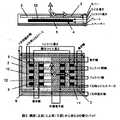
図1に示されるDDPパッドは実質的に同一平面内にあるコイル2およびコイル3を基本的に備えており、これらのコイルは磁気的に関連づけられてコア4の最上部に位置している。図からわかるように、コア4はフェライトストリップまたはフェライトバー5などの単一長の複数の磁気透過性素材からなり、各フェライトストリップまたはフェライトバーは互いに平行に間隔をあけて配置されている。パッド構造はコアが載置されているスペーサー6とスペーサーの下側にあるプレート7を含んでいる。いくつかの実施態様においては、カバー8が平面状のコイル2とコイル3のもう一方の表面に設けられる。詰め物(パディング)9をパッドの周辺部のあたりに備えてもよい。示されるように、コイル2とコイル3はそれぞれ磁極領域10、11を画している。図1に示すDDPパッド構造は、IPT電力伝達の利用形態、たとえば車両の充電など、に適しており、良好な特性を示すものである。コイル2とコイル3は位相が異なるように結線され、単一のインバータが固定位置で時間変化する磁界を生成し、この磁界は、良好な結合がされる電気車両の電力伝達に適した距離におかれたレシーバー(たとえば、実質的に同一の磁気的設計がされたもの)に結合している。The DDP pad shown in FIG. 1 basically comprises a
次に図2では、図1のDDP構造が示されているが、さらに積分コイル(クオドラチャーコイル)12が含まれている(ここでは、DDPQパッドという。)。適切なインバータによって励磁された時の図1のDDPパッドのような磁束生成器において、図2に示す構造がラテラル方向へ移動した際の電力伝達プロファイルを積分コイルによって改善するものである。積分コイルによりレシーバーパッドが捕捉した磁界の「垂直」成分から電力を抽出することができる。一方、他のコイル2とコイル3は捕捉した磁束の「水平」成分から電力を抽出することを容易にする。したがって、図2の構造は磁束のレシーバーとして適するものである。Next, FIG. 2 shows the DDP structure of FIG. 1, but further includes an integrating coil (quadrature coil) 12 (herein referred to as a DDPQ pad). In a magnetic flux generator such as the DDP pad of FIG. 1 when excited by an appropriate inverter, the power transfer profile when the structure shown in FIG. 2 moves laterally is improved by an integrating coil. The integration coil can extract power from the “vertical” component of the magnetic field captured by the receiver pad. On the other hand, the
次に図3では、バイポーラパッドまたはBPPパッドとして本明細書で参照される他の構造が示されている。BPPパッドは上記のように図1および図2で論じたDDPパッドと同様な構造をしている。BPPパッドは、電気車両の充電及び給電について適切な距離にある2次側のレシーバーに良好な磁気的結合をすることができる。Referring now to FIG. 3, another structure referred to herein as a bipolar pad or BPP pad is shown. The BPP pad has the same structure as the DDP pad discussed in FIGS. 1 and 2 as described above. The BPP pad can provide a good magnetic coupling to the secondary receiver at an appropriate distance for charging and powering the electric vehicle.
BPPパッドは、下から上に、アルミニウムプレート7、誘電体であるスペーサー6、4列に並ぶフェライトバー5(ここでは、「フェライト」という。)を備える平面状のコア4、実質的に同一平面にあるがオーバーラップがあり理想的には長方形の形状でラテラル方向に拡がっている2つの平面状のコイル2,3(実際には、これらはリッツ線を巻きやすくするために楕円形状となる。)および誘電体であるカバー8から構成される。コア4は遮蔽体として働き、理想的にはすべての磁束がコア4からパッドの最上部に向けて放たれる。プレート7は、単に、a)ある環境下でコア4の下に存在する場合がある小規模の漏洩磁界または擬似的な磁界を除去し、b)構造上の強度を加える、というものである。
BPPは図3に示されており、表A1はシミュレーションや実験的なプロトタイプから実際の寸法を定めたものである。The BPP pad includes, from bottom to top, a flat core 4 including an
The BPP is shown in FIG. 3, and Table A1 defines actual dimensions from simulations and experimental prototypes.
後述のように、BPPの磁気的な構造は、1次側のコイル2、3のいずれの間にも実質的に相互の磁気的結合がないように設計されている。このため、コイル間に結合電圧が生じるとコイルの電力出力に悪影響を与えるのであるが、互いに結合電圧を誘導することなく、いずれのコイルもどのような振幅または位相においても独立に動作させることができる。As will be described later, the magnetic structure of the BPP is designed so that there is substantially no mutual magnetic coupling between the
ある動作モードにおいては、BPP内のこれら2つのコイルは、別々ではあるが同期させた2つのインバータを用いて、既知の電流強度と位相差をもって動作させることができる。もしこれらのコイルが理想的に完全に磁気的に非結合になると、1次側のインバータの間の電力伝達がされることはなく、2次側のレシーバーへの電力伝達は制限されない。In one mode of operation, these two coils in the BPP can be operated with a known current strength and phase difference using two separate but synchronized inverters. If these coils are ideally completely magnetically decoupled, no power is transferred between the primary side inverters and power transfer to the secondary side receiver is not limited.
ひとつの実施態様において、2つのインバータが同期されているが同一RMS(平方自乗平均)の強度を有する電流を生成するように作動され、コイル2およびコイル3が90度異なる位相角で作動される。固定位置の利用形態においては、このことは所望の動作周波数で共振するように同調されたLCL構造を有する2つのHブリッジのインバータとされるだろう。各ケースの最後のLは一部がパッドのインダクタンスを用いて構成される。メイン側からの入力電子回路を単純にするために1次側のインバータは共通のDCバスを有することが好ましい。コイル2およびコイル3の電流の間に90度の位相の隔たりを有することにより、DDPのような固定位置で時間的に変化する磁界ではなく、空間的に変化するとともに時間的に変化する磁界が作られる。これは、図7に示されており、その左欄は、DDPパッドを表し、右欄は、BPPパッドを表している。BPPの磁界の空間的な変化は、コイル2およびコイル3の磁極の間で交互にスライドする動きとして現れている。In one embodiment, the two inverters are synchronized but operated to produce a current having the same RMS (root mean square) intensity, and
留意すべきことは、たとえば、ICNIRP(国際非電離放射線学会)に適合させるようにするなど、磁気的に結合されたレシーバーの動作中のオフセットによる漏洩磁界を防止するために、トランスミッターの片側から放出される磁界を減少させるというニーズがあるとするならば、コイルを流れる電流の間の相対的な位相および/または強度を変化させることにより、そのような磁界を形成することに用いることができる点である。このような場合は、より大きい磁界強度が必要とされる箇所や磁界強度を減少させるべき箇所をセンシングするセンサーの出力に応じて磁界の向きを決めることができる。また、磁界が必要とされるパッドの箇所により磁界強度が時間的に変化するが空間的に固定である場合も同様である。It should be noted that the emission from one side of the transmitter to prevent leakage magnetic fields due to offsets during operation of the magnetically coupled receiver, for example to conform to ICNIRP (International Society for Non-Ionizing Radiation) If there is a need to reduce the applied magnetic field, it can be used to create such a magnetic field by changing the relative phase and / or strength between the currents flowing through the coil. It is. In such a case, the direction of the magnetic field can be determined according to the output of the sensor that senses a location where a higher magnetic field strength is required or a location where the magnetic field strength should be reduced. The same applies to the case where the magnetic field strength changes with time depending on the location of the pad where a magnetic field is required, but is spatially fixed.
また別の実施形態では、コイル2およびコイル3は、180度異なる位相で動作させることも可能であり、両者をひとつのインバータで単純に接続するようにすることができる(DDPで作動させる場合)。この単一位相動作モードは、2番目に可能な動作モードであって、固定位置で時間変化のある磁界を生成する電子制御と電力変換を単純なものとする。In another embodiment, the
比較の手段として、スライドして時間変化する磁界を有するBPPの電力伝達プロフィールは、同一の電流と周波数(数値は表A2に定められている。)において単一位相である1次側電源から駆動されるDDP磁気構造の電力伝達プロフィールに対して評価される。
両システムは、同一の高さとオフセット(数値は表A3に定められている。)において同一のDDQPレシーバー(すなわち、磁束レシーバーとして用いられている図2のような積分コイルを含むDDPパッド)に結合しており、同一条件の下に評価されている。As a means of comparison, the power transfer profile of a BPP with a sliding time-varying magnetic field is driven from a primary power source that is single phase at the same current and frequency (numerical values are defined in Table A2). Is evaluated against the power transfer profile of the DDP magnetic structure.
Both systems are coupled to the same DDQP receiver (ie, a DDP pad containing an integrating coil as in FIG. 2 used as a flux receiver) at the same height and offset (numerical values are defined in Table A3). And are evaluated under the same conditions.
与えられたBPPは、スライドして時間変化する磁界、と呼ばれるものを創出する。コイル2およびコイル3がその上方に置かれているベース内に用いられた4つのフェライトストリップ5の好ましい長さを決定することが望ましい。既知のDDPでは、これらのフェライトストリップ5は電力伝達を改善するために用いられ、2次側の電力レシーバーに最もよく結合するように制御された主に片側からの磁界が作られる。他方、用いられるフェライトの数を最小として、重量を最小にするとともにパッドのインダクタンスを制限している。このスライドして変化する磁界では、フェライトストリップは巻かれているコイルの下側に延びているのが好ましいことが示されており、そうでないと磁界はレシーバーの方向である上方に向かうようにできない。A given BPP creates what is called a magnetic field that slides and changes over time. It is desirable to determine the preferred length of the four
この評価では、フェライトストリップ5は、それぞれ93mmの基準長さの簡単に利用できるスラブを用いて構成された。各ストリップは、便宜上、この基準長さの整数倍が選ばれた。6枚(558mm)、8枚(744mm)、および10枚(930mm)のスラブを一まとめにした構成が研究された。すべての設計において(10枚のスラブのフェライト構成を除く)、BPPパッドの外形寸法はDDPと同一にして、同一条件で比較できるようにした。しかしながら、10枚のフェライト構成ではトランスミッターパッド(もしくはジェネレータパッド)の全長(x方向)を長くせざるを得なくなり、基準長さを越えて200mm増加している(比較対象であるDDP構成を含む他のすべてのパッドと比較して。)。したがって、10枚のフェライト構成はコイル寸法を越えたフェライトに対する延長のインパクトを考慮する評価に唯一含まれている。表A1で示すように、コイル同士のオーバーラップは、1次側コイルの間で生じる相互の磁気的結合を避けるように構成されているが、3つのBPPコイルのどの構成においても、2つのコイルの端部と端部の距離は同一である。In this evaluation, the
BPPの2つの1次側コイル2,3は、互いに任意のオーバーラップをもって置かれると、コイル間に相互の磁気的結合が生じる。しかしながら、オーバーラップをコイル幅に対しある割合になるようにすると、相互の磁気的結合はほぼゼロとなる。この割合をr0と表記する。オーバーラップは、各1次側コイル間にまったく相互結合が存在しないようにすることが理想的であるが、フェライトが存在するため簡単ではない。しかし、ひとつのコイルを固定して、これを固定した周波数においてあらかじめ決めた電流を流して励磁することにより、決定することができる(たとえば、適切な3Dシミュレータによったり、適切な実験的構成を用いたりすればよい)。そうすると、2つ目のコイルに誘導された開回路電圧を測定することができる。この2つ目のコイルを動かしてオーバーラップを変化させると、結合電圧が変化する。これを最小化する(理想的にはゼロとする)と、理想的な相対位置が構成できる。図4に示すように、最適なオーバーラップは、コイルの下側のフェライトストリップの長さによって変わるものである。6枚、8枚および10枚のフェライトからなるパッドに対し、オーバーラップの割合r0は、それぞれ0.53、0.34および0.25であることがわかった。When the two
有限要素法を用いるソフトウェアであるJMAG Studio(商標)バージョン10.0を用いて、すべての磁気的構成についてのシミュレーションを行った。シミュレーションの出力の有効性は、プロトタイプであるBPPを実験室で構成しシミュレーションと比較することにより確認した。BPPは、ベース内に6枚のフェライトスラブからなるフェライトストリップを用いている。このスケールモデルは、表A1のBPPの外形寸法を用いたが、構成を単純にするため、各コイルは10回巻きとした。レシーバーは表A3に示すDDQPコイルとした。図5に示すように、実測値とシミュレーション値を比較し良好な相関があることが示された。All magnetic configurations were simulated using JMAG Studio ™ version 10.0, software that uses the finite element method. The effectiveness of the simulation output was confirmed by constructing a prototype BPP in the laboratory and comparing it with the simulation. BPP uses a ferrite strip composed of six ferrite slabs in a base. This scale model used the outer dimensions of the BPP in Table A1, but each coil was wound 10 times to simplify the configuration. The receiver was a DDQP coil shown in Table A3. As shown in FIG. 5, the measured value and the simulation value were compared and it was shown that there was a good correlation.
ここに与えられた電力プロフィールは非補償VA電力出力全体であり、これはレシーバーの開回路電圧(Voc)および短絡回路電流(Isc)を測定して決定したものである。
非補償VAは、よく知られたパッドの電力性能の評価尺度であり、Su=Voc×Iscにより与えられる。DDQPレシーバーは、コイル2、3(これらは直列接続とする)と積分コイル(Qコイル)12の2つのセットのコイルを有する。このケースでは、非補償電力は両方のセットにそれぞれ別々に見出される。ピックアップから供給されて利用できる全非補償電力は、2つのセットのコイルから供給される電力の和として単純に計算される電力全体をさし、この電力全体が、電力伝達プロフィールの基礎となるものである。The power profile given here is the total uncompensated VA power output, which is determined by measuring the open circuit voltage (Voc ) and short circuit current (Isc ) of the receiver.
Uncompensated VA is a well-known measure of pad power performance and is given by Su = Voc × Isc . The DDQP receiver has two sets of coils:
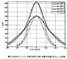
したがって、各BPPの設計の電力伝達プロフィールは、3Dシミュレーションを用いて、図6に示すように、確実に決定することができる。ここに、BPPは20kHzの23A(平方自乗平均)の電流で励磁され、他方レシーバーはDDQPである。相対的な位置を決めるパラメータは、オフセット距離といい、デカルト座標系でxos(ラテラル(幅)方向)、 yos(長手方向) およびzos(垂直方向)である。誘電体であるカバー8を介して互いの上部が触れた状態の2つのパッドの相対位置は、(0,0,0)である。垂直方向のオフセットzosは、200mmである。Thus, the power transfer profile for each BPP design can be reliably determined using 3D simulation, as shown in FIG. Here, the BPP is excited with a current of 23 kHz (root mean square) at 20 kHz, while the receiver is a DDQP. The parameter that determines the relative position is referred to as an offset distance, and is xos (lateral (width) direction), yos (longitudinal direction), and zos (vertical direction) in a Cartesian coordinate system. The relative positions of the two pads in a state where the upper portions of the two pads are touched via the cover 8 that is a dielectric are (0, 0, 0). The vertical offset zos is 200 mm.
注目すべきことは、コイルの下側にあるフェライトを延ばすと、電力の無視しえない増加があることである。フェライトは少なくともコイル2,3全体の下にあるように延ばすべきことは明らかである(8枚のフェライトスラブを有するBPP)。フェライトがベースに加えられるとBPPからの非補償電力が急激に増加する理由は、その磁界が固定位置にないという性質があるからである。BPPパッドの近傍の磁界は、その表面を横切ってスライドする波として最もよく記述することができる。DDPは単一位相であるためパルス状に上下に脈動するが、これとは異なる。このスライドする性質は、図7に明らかに示されているように、BPPとDDPの根本的な違いである。図7は、半サイクルの間、位相ごとに磁束密度を比較している。図7では、BPP8とDDPがDDQPレシーバーに結合している磁界について両者のプロットが示されており、これらのプロットは1次側の共振電流の一サイクル全体におけるいくつかの時点のものである。上から下に、0,30,60,90,120および150度のもの(バイポーラにおいては他方の位相は90度離れて動作する。)を示している。左側の欄のプロットは、8つのフェライトスラブを用いたBPPパッドのものである。右側の欄のプロットは、DDPパッドのものである。単一位相のDDPパッドからの磁界はパルス状に上下し、パッドの中心に非常に強い磁界を有している。他方、BPPは、より一定に近い磁界パターンを有するが、このパターンは位相が進むにつれてスライドする波のようにパッドの表面を移動していく。It should be noted that there is a non-negligible increase in power when extending the ferrite under the coil. Obviously, the ferrite should extend at least under the
BPPのスライドする波は、パッドのエッジ部に局所的に大きい磁界を作る。他方、DDPパッドは、パッドの中心に強い磁界を保持する。6枚のバージョンでは、コイル端部の下側にフェライトが存在せず、磁界は誘電体であるフィリング材料6(木材)によって十分詰められていない。したがって、上方には放射されないが、パッドのアルミニウム製のベースプレート7に過電流を誘導する。図8では、3種類の構成は、同一の位相で比較されている。図8は、0度であって垂直方向のオフセットを有するDDQPレシーバーが存在する場合のBPPパッドの磁界のプロットを示しており、それぞれ6枚(上)、8枚(中)、10枚(下)のスラブが、ベース内にフェライトストリップを形成している。磁束密度は定性的には異なるように現れており、特に右側のエッジ付近は磁束密度が8枚構成および10枚構成のものでは高くなっているが、6枚構成のものではそうなっていない。
10枚構成のものでは、磁束はさらに限定されており、トラックパッドの側部の「回り込み」磁界も少ない。繰り返すが「回り込み」磁界は、電力伝達を減少させるファクターである。10枚構成のものでは磁界はピックアップ(すなわち、レシーバーパッド)の方向に押し出されることはないからであり、これは好ましいことである。The sliding wave of the BPP creates a large magnetic field locally at the pad edge. On the other hand, the DDP pad holds a strong magnetic field in the center of the pad. In the six version, there is no ferrite under the coil end and the magnetic field is not fully packed by the filling material 6 (wood) which is a dielectric. Therefore, although not radiated upward, an overcurrent is induced in the
In the 10-sheet configuration, the magnetic flux is more limited and there is less “wraparound” magnetic field on the sides of the trackpad. Again, the “wraparound” magnetic field is a factor that reduces power transfer. This is preferable because the magnetic field is not pushed in the direction of the pickup (that is, the receiver pad) in the ten-sheet configuration.
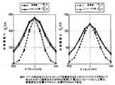
図9において、各フェライトベースストリップに8枚のフェライトスラブを備えるBPP(BPP8)がDDPと比較されている。BPP8の電力伝達プロフィールはDDPのプロフィールと比較すると、その形状とその最大値において大きな違いがあることがわかる。示されているように、BPP8は、最大電力がDDPの約70%であってDDPと同様の電力プロフィールを有している。しかしながら、示されている電力レベルと達成した結合状態は、たとえば電気車両への電力について実際の利用形態に必要となる距離において適するレベルを実現するものであり、さらにDDP電力プロフィールに見られるようなオフセットのある場合のピーク周辺の電力の変化については、その割合が大きくないことが示されている。この電力の変化の割合が限定されることは、電力ハイウェイへの利用形態において、ラテラル方向への動きに対して電力の厳しい変動がないであろうことが有利な点である。In FIG. 9, BPP (BPP8) with eight ferrite slabs in each ferrite base strip is compared with DDP. Compared with the DDP profile, the BPP8 power transfer profile shows a significant difference in its shape and its maximum value. As shown, BPP 8 has a power profile similar to DDP with a maximum power of about 70% of DDP. However, the power levels shown and the coupling conditions achieved achieve, for example, a level suitable for the distance required for the actual usage for the power to the electric vehicle, and as seen in the DDP power profile. It is shown that the ratio of power change around the peak when there is an offset is not large. This limited rate of change in power is advantageous in that there will be no severe fluctuations in power with respect to lateral movements in power highway applications.

上記の記述では、公知の均等物を有する本発明の特定の完成品または構成要素について言及してきたが、これらの均等物は個々に記載されているかのように本明細書に組み込まれて含まれる。Although the above description refers to particular finished products or components of the invention having known equivalents, these equivalents are hereby incorporated by reference as if individually set forth. .
本発明は、実施例と本発明の可能な実施態様を参照して記載されているが、本発明の範囲と趣旨から離れることのない改変や改善をなおその上に行うことができることが理解されよう。Although the invention has been described with reference to examples and possible embodiments of the invention, it will be understood that modifications and improvements can be made thereon without departing from the scope and spirit of the invention. Like.
Claims (32)
Translated fromJapanese磁気透過性のコアと、前記コアに磁気的に関連づけられた平面状の2つの部分的にオーバーラップしているコイルとを備え、それにより前記2つのコイルの間には相互の磁気的結合が実質的になくなるようにされており、
前記磁気透過性のコアは、所定長さの複数の磁気透過性素材を含み、これらの磁気透過性素材は互いに平行しているが離隔して前記コイルの全体にわたって延びる、磁束パッド。A magnetic flux pad for generating or receiving magnetic flux,
A magnetically permeable core and two planar overlapping coils that are magnetically associated with the core so that there is mutual magnetic coupling between the two coils. Is virtually eliminated,
The magnetically permeable core includes a plurality of magnetically permeable materials having a predetermined length, and the magnetically permeable materials are parallel to each other but are spaced apart and extend over the entire coil.
前記電源装置は、請求項1乃至13の何れか1項に記載の磁束を生成する磁束パッドと、電源とを含み、
前記パッドは、磁気透過性のコアと、前記コアに磁気的に関連づけられた平面状の2つのオーバーラップしているコイルとを備え、それより前記2つのコイルの間には相互の磁気的結合が実質的になくなるようにされており、
前記電源は、一方のコイルを流れる電流と、該電流とは異なる位相を有する他方のコイルを流れる電流とを供給するように構成されている、前記電源装置。A power supply for an inductive power transfer (IPT) system comprising:
The power supply device includes a magnetic flux pad for generating magnetic flux according to any one of claims 1 to13 , and a power supply.
The pad comprises a magnetically permeable core and two planar overlapping coils that are magnetically associated with the core so that there is a mutual magnetic coupling between the two coils. Is virtually eliminated,
The power supply device is configured to supply a current flowing through one coil and a current flowing through the other coil having a phase different from the current.
互いに平行しているが離隔して前記コイルの全体にわたって延びる所定長さの複数の磁気透過性素材を含んでなるコアを用意すること、
および、
一方のコイルを流れる電流と異なる位相および/または強度を有する他方のコイルを流れる電流を供給すること、
を含む、ワイヤレス電力伝送を容易にするための磁束の生成方法。Providing two planar coils that overlap each other but have minimal mutual magnetic coupling;
Providing a core comprising a plurality of magnetically permeable materials of a predetermined length that are parallel to each other but spaced apart and extending across the coil;
and,
Supplying a current through the other coil having a phase and / or strength different from that of the current through the one coil;
A magnetic flux generation method for facilitating wireless power transmission.
Applications Claiming Priority (2)
| Application Number | Priority Date | Filing Date | Title |
|---|---|---|---|
| US27370109P | 2009-08-07 | 2009-08-07 | |
| US16/273,701 | 2009-08-07 |
Related Parent Applications (1)
| Application Number | Title | Priority Date | Filing Date |
|---|---|---|---|
| JP2015208300ADivisionJP6193329B2 (en) | 2009-08-07 | 2015-10-22 | Inductive power transfer system |
Publications (2)
| Publication Number | Publication Date |
|---|---|
| JP2017120916A JP2017120916A (en) | 2017-07-06 |
| JP6585104B2true JP6585104B2 (en) | 2019-10-02 |
Family
ID=43544512
Family Applications (6)
| Application Number | Title | Priority Date | Filing Date |
|---|---|---|---|
| JP2012523582APendingJP2013501665A (en) | 2009-08-07 | 2010-08-06 | Electric vehicle system that obtains electric energy from the road |
| JP2012523583APendingJP2013502193A (en) | 2009-08-07 | 2010-08-06 | Inductive power transfer system |
| JP2014212113APendingJP2015071413A (en) | 2009-08-07 | 2014-10-16 | Electric vehicle system that obtains electric energy from the road |
| JP2015208300AActiveJP6193329B2 (en) | 2009-08-07 | 2015-10-22 | Inductive power transfer system |
| JP2017010860AActiveJP6585104B2 (en) | 2009-08-07 | 2017-01-25 | Inductive power transfer system |
| JP2018006491APendingJP2018079932A (en) | 2009-08-07 | 2018-01-18 | Roadway powered electric vehicle system |
Family Applications Before (4)
| Application Number | Title | Priority Date | Filing Date |
|---|---|---|---|
| JP2012523582APendingJP2013501665A (en) | 2009-08-07 | 2010-08-06 | Electric vehicle system that obtains electric energy from the road |
| JP2012523583APendingJP2013502193A (en) | 2009-08-07 | 2010-08-06 | Inductive power transfer system |
| JP2014212113APendingJP2015071413A (en) | 2009-08-07 | 2014-10-16 | Electric vehicle system that obtains electric energy from the road |
| JP2015208300AActiveJP6193329B2 (en) | 2009-08-07 | 2015-10-22 | Inductive power transfer system |
Family Applications After (1)
| Application Number | Title | Priority Date | Filing Date |
|---|---|---|---|
| JP2018006491APendingJP2018079932A (en) | 2009-08-07 | 2018-01-18 | Roadway powered electric vehicle system |
Country Status (7)
| Country | Link |
|---|---|
| US (3) | US10325717B2 (en) |
| EP (2) | EP2462679B1 (en) |
| JP (6) | JP2013501665A (en) |
| KR (3) | KR101780758B1 (en) |
| CN (3) | CN102577011B (en) |
| IN (2) | IN2012DN01935A (en) |
| WO (2) | WO2011016736A2 (en) |
Families Citing this family (197)
| Publication number | Priority date | Publication date | Assignee | Title |
|---|---|---|---|---|
| EP2329585B1 (en)* | 2008-09-11 | 2021-04-21 | Auckland UniServices Limited | Inductively coupled ac power transfer |
| WO2010131348A1 (en)* | 2009-05-14 | 2010-11-18 | トヨタ自動車株式会社 | Vehicle charging unit |
| IN2012DN01935A (en) | 2009-08-07 | 2015-08-21 | Auckland Uniservices Ltd | |
| WO2011046453A1 (en)* | 2009-10-12 | 2011-04-21 | Auckland Uniservices Limited | Inductively controlled series resonant ac power transfer |
| KR101970324B1 (en)* | 2010-08-06 | 2019-04-18 | 오클랜드 유니서비시즈 리미티드 | Inductive power receiver apparatus |
| NZ589865A (en)* | 2010-12-10 | 2013-06-28 | Auckland Uniservices Ltd | Inductive power transfer pick-up with separate AC and DC outputs |
| DE102010054848A1 (en)* | 2010-12-16 | 2012-06-21 | Conductix-Wampfler Ag | Device for inductive transmission of electrical energy |
| US20120169131A1 (en)* | 2010-12-29 | 2012-07-05 | Choudhary Vijay N | Phase shift power transfer |
| US20130293191A1 (en) | 2011-01-26 | 2013-11-07 | Panasonic Corporation | Non-contact charging module and non-contact charging instrument |
| DE102011004348A1 (en)* | 2011-02-17 | 2012-08-23 | Beckhoff Automation Gmbh | Method and position detection device for detecting a position of a movable element of a drive device |
| US9954361B2 (en) | 2011-04-08 | 2018-04-24 | Auckland Uniservices Limited | Local demand side power management for electric utility networks |
| US20120311363A1 (en)* | 2011-05-31 | 2012-12-06 | Nam Yun Kim | Wireless power transmission and charging system, and communication method of wireless power transmission and charging system |
| JP5342073B2 (en) | 2011-06-14 | 2013-11-13 | パナソニック株式会社 | Communication device |
| KR101944476B1 (en)* | 2011-07-08 | 2019-02-01 | 오클랜드 유니서비시즈 리미티드 | Interoperability of magnetic structures for inductive power transfer systems |
| DE102011078883A1 (en)* | 2011-07-08 | 2013-01-10 | Robert Bosch Gmbh | Inductive charging device and control method |
| WO2013019124A1 (en)* | 2011-07-19 | 2013-02-07 | Auckland Uniservices Limited | Double conductor single phase inductive power transfer tracks |
| KR101363950B1 (en)* | 2011-08-26 | 2014-02-20 | 한국과학기술원 | Pickup with Compensation Winding for Electric Vehicle |
| DE102011112610B4 (en)* | 2011-09-05 | 2020-06-04 | Grenzebach Maschinenbau Gmbh | Device and method for the wireless transmission of electrical energy to vehicles in the manner of "mobile petrol pumps", as well as a computer program and machine-readable carrier |
| EP2751900B1 (en) | 2011-09-07 | 2021-08-04 | Auckland UniServices Limited | Magnetic field shaping for inductive power transfer |
| KR101305833B1 (en) | 2011-09-09 | 2013-09-06 | 엘지이노텍 주식회사 | A wireless power realy apparatus and transmission system |
| JP6348844B2 (en) | 2011-10-28 | 2018-06-27 | オークランド ユニサービシズ リミテッドAuckland Uniservices Limited | Non-ferrite structure for inductive power transfer |
| US10204734B2 (en) | 2011-11-02 | 2019-02-12 | Panasonic Corporation | Electronic device including non-contact charging module and near field communication antenna |
| US9607757B2 (en) | 2011-11-02 | 2017-03-28 | Panasonic Corporation | Non-contact wireless communication coil, transmission coil, and portable wireless terminal |
| DE102011119259A1 (en) | 2011-11-24 | 2013-05-29 | Bombardier Transportation Gmbh | Doppler rectifier for multiphase contactless power transmission system |
| CN104272545B (en) | 2011-12-16 | 2018-06-12 | 奥克兰联合服务有限公司 | Inductive power transfer system and method |
| BR112014014707A2 (en)* | 2011-12-22 | 2017-06-13 | Koninklijke Philips Nv | system for charging one or more target devices with a receptacle charger and method for controlling the loading of at least one target device positioned in a receptacle |
| DE102012000408A1 (en)* | 2012-01-12 | 2013-07-18 | Phoenix Contact Gmbh & Co. Kg | Resonant inductive power supply device |
| DE102012000409A1 (en) | 2012-01-12 | 2013-07-18 | Phoenix Contact Gmbh & Co. Kg | Modular data system with inductive energy transfer |
| KR102091222B1 (en)* | 2012-02-02 | 2020-03-20 | 오클랜드 유니서비시즈 리미티드 | Var control for inductive power transfer systems |
| US20150236513A1 (en) | 2012-02-16 | 2015-08-20 | Auckland Uniservices Limited | Multiple coil flux pad |
| JP2013169122A (en) | 2012-02-17 | 2013-08-29 | Panasonic Corp | Non-contact charge module and portable terminal having the same |
| RU2596613C2 (en) | 2012-02-22 | 2016-09-10 | Тойота Дзидося Кабусики Кайся | Contactless power transmission, power receiving device and system for contactless power transmission |
| CN102611205B (en)* | 2012-03-08 | 2014-12-10 | 重庆大学 | Efficient dynamic-sensing power supply system for electric vehicle |
| WO2013141718A1 (en)* | 2012-03-20 | 2013-09-26 | Auckland Uniservices Limited | Winding arrangements in wireless power transfer systems |
| GB2502084A (en)* | 2012-05-14 | 2013-11-20 | Bombardier Transp Gmbh | Arrangement for providing vehicles with energy comprising magnetisable material |
| JP6024195B2 (en)* | 2012-05-15 | 2016-11-09 | スミダコーポレーション株式会社 | Contactless power supply system and power transmission coil for contactless power supply system |
| EP2854145B1 (en)* | 2012-05-21 | 2018-03-28 | Technova Inc. | Contactless electrical-power-supplying transformer for moving body |
| DE102012209898A1 (en)* | 2012-06-13 | 2013-12-19 | Siemens Aktiengesellschaft | Arrangement for inductive wireless delivery of energy |
| GB2503484A (en)* | 2012-06-27 | 2014-01-01 | Bombardier Transp Gmbh | Inductive vehicle charging station and method with lateral electromagnetic shielding |
| JP6008237B2 (en) | 2012-06-28 | 2016-10-19 | パナソニックIpマネジメント株式会社 | Mobile device |
| JP6112383B2 (en) | 2012-06-28 | 2017-04-12 | パナソニックIpマネジメント株式会社 | Mobile device |
| JP6378175B2 (en)* | 2012-07-09 | 2018-08-22 | オークランド ユニサービシズ リミテッドAuckland Uniservices Limited | Magnetic flux coupling device and magnetic structure thereof |
| KR20220150404A (en)* | 2012-08-28 | 2022-11-10 | 오클랜드 유니서비시즈 리미티드 | A polyphase inductive power transfer system with individual control of phases |
| KR102306645B1 (en) | 2012-08-31 | 2021-09-30 | 오클랜드 유니서비시즈 리미티드 | Improved efficiency non-self tuning wireless power transfer systems |
| AU2013313724B2 (en) | 2012-09-06 | 2017-11-30 | Auckland Uniservices Limited | Local demand side power management for electric utility networks |
| US9666357B2 (en) | 2012-09-11 | 2017-05-30 | Qualcomm Incorporated | Apparatus system, and method for wirelessly receiving power using conductive structures |
| KR101976063B1 (en) | 2012-10-05 | 2019-05-09 | 삼성디스플레이 주식회사 | Apparatus and method for sensing bending of a flexible display using mutual inductance |
| US10014104B2 (en)* | 2012-11-02 | 2018-07-03 | Qualcomm Incorporated | Coil arrangements in wireless power transfer systems for low electromagnetic emissions |
| CN104885333B (en)* | 2012-11-09 | 2018-05-15 | 加州理工学院 | Smart RF Lensing: Efficient, Dynamic, and Mobile Wireless Power Transfer |
| US11843260B2 (en) | 2012-11-09 | 2023-12-12 | California Institute Of Technology | Generator unit for wireless power transfer |
| US11616520B2 (en) | 2012-11-09 | 2023-03-28 | California Institute Of Technology | RF receiver |
| KR20150085827A (en)* | 2012-11-12 | 2015-07-24 | 오클랜드 유니서비시즈 리미티드 | Vehicle or moving object detection |
| DE102012023363B4 (en)* | 2012-11-29 | 2014-06-26 | Audi Ag | Subframe for a motor vehicle |
| US20140159673A1 (en)* | 2012-12-07 | 2014-06-12 | Samsung Electronics Co., Ltd. | Wireless charging apparatus and method |
| KR20140076993A (en)* | 2012-12-13 | 2014-06-23 | 엘지이노텍 주식회사 | Wireless power device |
| JP5286445B1 (en)* | 2012-12-28 | 2013-09-11 | 株式会社日立パワーソリューションズ | Wireless power feeder for electric mobile body |
| US9142990B2 (en) | 2013-01-18 | 2015-09-22 | Qualcomm Incorporated | Method of multi-coil operation and optimization |
| JP6164853B2 (en)* | 2013-01-28 | 2017-07-19 | 株式会社テクノバ | Non-contact power supply system while traveling |
| EP2984727B1 (en)* | 2013-03-27 | 2024-10-30 | Auckland UniServices Limited | Electromagnetic leakage field attenuation |
| GB2512855A (en) | 2013-04-09 | 2014-10-15 | Bombardier Transp Gmbh | Receiving device for receiving a magnetic field and for producing electric energy by magnetic induction |
| GB2512862A (en)* | 2013-04-09 | 2014-10-15 | Bombardier Transp Gmbh | Receiving device with coil of electric line for receiving a magnetic field and for producing electric energy by magnetic induction |
| US9520748B2 (en)* | 2013-04-17 | 2016-12-13 | El Wha Llc | Systems and methods for providing wireless power to a power-receiving device, and related power-receiving devices |
| ES2761337T3 (en)* | 2013-04-26 | 2020-05-19 | Use System Eng Holding B V | Power transfer system |
| US9676285B2 (en)* | 2013-05-01 | 2017-06-13 | Qualcomm Incorporated | Vehicle charging pad having reduced thickness |
| DE102013007971A1 (en)* | 2013-05-10 | 2014-11-27 | Audi Ag | Method for operating a charging device for single and multi-phase charging of an energy storage device of a motor vehicle and charging device |
| US9446674B2 (en)* | 2013-07-15 | 2016-09-20 | Qualcomm Incorporated | Systems, methods, and apparatus related to mutual detection and identification of electric vehicle and charging station |
| KR102125917B1 (en) | 2013-08-07 | 2020-07-08 | 엘지이노텍 주식회사 | Wireless power transmitting device |
| US9438064B2 (en)* | 2013-08-30 | 2016-09-06 | Qualcomm Incorporated | System and method for alignment and compatibility detection for a wireless power transfer system |
| US10186912B2 (en) | 2013-09-13 | 2019-01-22 | Qualcomm Incorporated | Pickup coil design for tight spaces and asymmetrical coupling |
| DE102013219536A1 (en)* | 2013-09-27 | 2015-04-02 | Siemens Aktiengesellschaft | Charging station for wireless energy-related coupling of an electrically driven vehicle |
| US10396596B2 (en) | 2013-11-13 | 2019-08-27 | Apple Inc. | Transmitter for inductive power transfer systems |
| EP3072214B1 (en)* | 2013-11-22 | 2018-10-10 | California Institute of Technology | Generator unit for wireless power transfer |
| JP6156115B2 (en) | 2013-12-13 | 2017-07-05 | トヨタ自動車株式会社 | Power transmission equipment |
| US9837204B2 (en) | 2013-12-17 | 2017-12-05 | Qualcomm Incorporated | Coil topologies for inductive power transfer |
| GB2521676B (en)* | 2013-12-31 | 2016-08-03 | Electric Road Ltd | System and method for powering an electric vehicle on a road |
| US9815379B2 (en)* | 2014-01-21 | 2017-11-14 | Qualcomm Incorporated | Systems and methods for electric vehicle induction coil alignment |
| JP6226500B2 (en)* | 2014-01-21 | 2017-11-08 | 株式会社テクノバ | Contactless power supply system |
| KR102363633B1 (en) | 2014-02-20 | 2022-02-17 | 삼성전자주식회사 | Method for controlling wireless power transmitter and wireless power transmitter |
| WO2015126103A1 (en)* | 2014-02-20 | 2015-08-27 | 삼성전자주식회사 | Wireless power transmitter and method for controlling wireless power transmitter |
| JP2015159693A (en)* | 2014-02-25 | 2015-09-03 | 株式会社豊田自動織機 | Non-contact power transmission system and power reception device |
| WO2015132890A1 (en)* | 2014-03-04 | 2015-09-11 | 株式会社 テクノバ | System for wirelessly supplying power during moving |
| US9772401B2 (en) | 2014-03-17 | 2017-09-26 | Qualcomm Incorporated | Systems, methods, and apparatus for radar-based detection of objects in a predetermined space |
| JP6299320B2 (en)* | 2014-03-25 | 2018-03-28 | Tdk株式会社 | Coil unit and wireless power transmission device |
| JP6303684B2 (en)* | 2014-03-25 | 2018-04-04 | Tdk株式会社 | Coil unit and wireless power transmission device |
| US10083792B2 (en)* | 2014-05-14 | 2018-09-25 | Qualcomm Incorporated | System, method and apparatus for reducing the height of bipolar transmitters and/or receivers in electric vehicle charging |
| WO2015178781A1 (en) | 2014-05-19 | 2015-11-26 | Powerbyproxi Limited | Magnetically permeable core and an inductive power transfer coil arrangement |
| EP3146542A4 (en) | 2014-05-19 | 2017-06-14 | PowerbyProxi Limited | Magnetically permeable core and inductive power transfer coil arrangement |
| US9463705B2 (en)* | 2014-06-10 | 2016-10-11 | Qualcomm Incorporated | System and method for adaptive charging compliance control |
| CN106716570B (en) | 2014-07-08 | 2020-05-15 | 奥克兰联合服务有限公司 | Inductive power transfer equipment |
| CN106663528B (en)* | 2014-07-09 | 2020-05-05 | 奥克兰联合服务有限公司 | Inductive power system suitable for electric vehicle |
| EP3180835A4 (en) | 2014-08-12 | 2017-09-13 | PowerbyProxi Limited | System and method for power transfer |
| EP3183797B1 (en) | 2014-08-19 | 2020-10-07 | California Institute of Technology | Wireless power transfer |
| US9819208B2 (en)* | 2014-08-29 | 2017-11-14 | General Electronics Applications, Inc. | Battery management circuit having cell connections for batteries and a plurality of corresponding windings and diodes |
| US10513190B2 (en)* | 2014-09-10 | 2019-12-24 | Witricity Corporation | Methods and apparatus for tuning and controlling double couple inductive power transfer systems |
| US9680312B2 (en)* | 2014-09-10 | 2017-06-13 | Qualcomm Incorporated | System and method for reactive power control in dynamic inductive power transfer systems |
| CN115831569A (en) | 2014-09-11 | 2023-03-21 | 奥克兰联合服务有限公司 | Flux coupling structure with controlled flux cancellation |
| JP6327358B2 (en) | 2014-11-06 | 2018-05-23 | 富士通株式会社 | Power receiver and power transmission system |
| CN104539008A (en)* | 2014-12-18 | 2015-04-22 | 曹艺佳 | Electric vehicle road wireless charging system |
| US9960607B2 (en)* | 2014-12-29 | 2018-05-01 | Qualcomm Incorporated | Systems, methods and apparatus for reducing intra-base array network coupling |
| WO2016126167A1 (en) | 2015-02-03 | 2016-08-11 | Powerbyproxi Limited | Inductive power transmitter |
| US10566853B2 (en) | 2015-02-03 | 2020-02-18 | Apple Inc. | Inductive power transmitter |
| JP6402818B2 (en) | 2015-02-20 | 2018-10-10 | 富士通株式会社 | Power receiver and power transmission system |
| JP6402819B2 (en) | 2015-02-20 | 2018-10-10 | 富士通株式会社 | Power receiver and power transmission system |
| CN104901400B (en)* | 2015-04-30 | 2018-01-19 | 徐州凯思特机电科技有限公司 | A kind of electric automobile road surface dynamic high-efficiency induction charging system of rail-free positioner |
| WO2017023180A1 (en) | 2015-08-06 | 2017-02-09 | Auckland Uniservices Limited | Hybrid inductive power transfer system |
| SG10201700633QA (en)* | 2016-02-03 | 2017-09-28 | Gen Electric | System and method for protecting a wireless power transfer system |
| EP3436303B1 (en)* | 2016-03-29 | 2022-12-14 | Elonroad AB | Method for activating a powering segment in an electric road system and an electric road system |
| WO2017204663A1 (en) | 2016-05-25 | 2017-11-30 | Powerbyproxi Limited | A coil arrangement |
| WO2017209630A1 (en) | 2016-06-01 | 2017-12-07 | Powerbyproxi Limited | A powered joint with wireless transfer |
| US10239415B2 (en) | 2016-06-24 | 2019-03-26 | Qualcomm Incorporated | Base side vehicle identification using vehicle controller switching frequency |
| US20180015836A1 (en)* | 2016-07-17 | 2018-01-18 | Bezan Phiroz Madon | System for Automatically Connecting a Parked Vehicle to a Power Source, Using Intersecting Lines of Contacts |
| US11376966B2 (en) | 2016-07-19 | 2022-07-05 | Auckland Uniservices Limited | Electric vehicle detection for roadway wireless power transfer |
| WO2018026288A1 (en) | 2016-08-01 | 2018-02-08 | Auckland Uniservices Limited | Power transfer and leakage flux control |
| KR20180016311A (en) | 2016-08-05 | 2018-02-14 | 주식회사 아모센스 | Current transformer module and power supply apparatus having the same |
| US10354794B2 (en)* | 2016-08-25 | 2019-07-16 | Witricity Corporation | Multi-coil base pad with angled structure |
| CN110073572A (en) | 2016-09-16 | 2019-07-30 | Tdk电子股份有限公司 | Wireless power transmitter, Wireless power transmission system and the method for driving Wireless power transmission system |
| US20190260235A1 (en)* | 2016-09-16 | 2019-08-22 | Tdk Electronics Ag | Wireless Power Transmitter, Wireless Power Transmission System and Method for Driving a Wireless Power Transmission System |
| CN107846081A (en)* | 2016-09-21 | 2018-03-27 | 天津工业大学 | A kind of dynamic radio electric power system 3 D electromagnetic coupled structure design |
| CN107839486A (en)* | 2016-09-21 | 2018-03-27 | 天津工业大学 | A kind of energy coupling structure applied to dynamic radio electric power system designs |
| US10430026B2 (en) | 2016-10-05 | 2019-10-01 | Snap-On Incorporated | System and method for providing an interactive vehicle diagnostic display |
| US10430021B2 (en) | 2016-10-05 | 2019-10-01 | Snap-On Incorporated | System and method for providing an interactive vehicle diagnostic display |
| DE102016120108A1 (en)* | 2016-10-21 | 2018-04-26 | Endress+Hauser Process Solutions Ag | Method, communication module and system for transmitting diagnostic data of a field device in a process automation system |
| CN206834025U (en) | 2016-11-18 | 2018-01-02 | 鲍尔拜普罗克西有限公司 | Induction type power transmission line coil assembly |
| US11646152B2 (en) | 2016-11-25 | 2023-05-09 | Auckland Uniservices Limited | Current distribution and thermal regulation in inductive power transfer coupling structures |
| US11322983B2 (en)* | 2016-12-05 | 2022-05-03 | Auckland Uniservices Limited | Polyphase hybrid IPT system |
| US10978911B2 (en) | 2016-12-19 | 2021-04-13 | Apple Inc. | Inductive power transfer system |
| US10293700B2 (en) | 2016-12-22 | 2019-05-21 | Hyundai America Technical Center, Inc | Wireless charging system for electric vehicle with adjustable flux angle |
| WO2018151610A1 (en) | 2017-02-14 | 2018-08-23 | Aiguo Hu | Inductive power transfer |
| JP6610583B2 (en)* | 2017-03-09 | 2019-11-27 | Tdk株式会社 | Wireless power transmission system |
| CN107097669A (en)* | 2017-05-03 | 2017-08-29 | 南京农业大学 | A kind of source-series many hairdo wireless charging system for electric automobile of list |
| WO2018218252A1 (en) | 2017-05-26 | 2018-11-29 | California Institute Of Technology | Method and apparatus for dynamic rf lens focusing and tracking of wireless power recovery unit |
| WO2019000056A1 (en)* | 2017-06-28 | 2019-01-03 | Music Salih | Wireless transmission system of electricity for electric vehicles |
| US10507737B2 (en)* | 2017-08-07 | 2019-12-17 | Cisco Technology, Inc. | Gap control for vehicle wireless power transfer (WPT) |
| US10727693B2 (en)* | 2017-09-21 | 2020-07-28 | Utah State University | Dynamic inductive wireless power transmitter system with a power transmitter module |
| CN107972533B (en)* | 2017-10-19 | 2020-07-31 | 北京全路通信信号研究设计院集团有限公司 | In-station bidirectional reflux circuit and implementation method |
| US10850634B2 (en)* | 2017-10-20 | 2020-12-01 | Toyota Motor Engineering & Manufacturing North America, Inc. | Multi-turn configurable grid charging coil |
| US11431196B2 (en) | 2017-12-01 | 2022-08-30 | Auckland Uniservices Limited | Misalignment tolerant hybrid wireless power transfer system |
| PL424628A1 (en)* | 2018-02-20 | 2019-08-26 | Izabela Boroń | Uninterruptible power supply, UPS - preferably in power engineering |
| US20210001733A1 (en)* | 2018-02-23 | 2021-01-07 | Industrieanlagen-Betriebsgesellschaft Mbh | Device for generating a magnetic field, in particular for an inductive charging system, and primary device of an inductive charging system for dynamically charging vehicles |
| US10593468B2 (en) | 2018-04-05 | 2020-03-17 | Apple Inc. | Inductive power transfer assembly |
| JP7275648B2 (en)* | 2018-06-26 | 2023-05-18 | 株式会社デンソー | In-motion wireless power supply system |
| US11214163B2 (en)* | 2018-12-04 | 2022-01-04 | Cisco Technology, Inc. | Coil association in multisite stationary wireless power transfer (WPT) and (quasi-)dynamic WPT deployments |
| CN109532526A (en)* | 2019-01-04 | 2019-03-29 | 重庆大学 | The electric motor car wireless charging system and control method of ground surface end twin coil position detection |
| CN109606145A (en)* | 2019-01-04 | 2019-04-12 | 重庆大学 | Dynamic wireless charging system based on group control |
| KR102249729B1 (en)* | 2019-11-20 | 2021-05-12 | 한국과학기술원 | Wireless charging power supply system and pick-up system during running of electric vehicles and industrial equipment |
| WO2020159323A1 (en)* | 2019-02-01 | 2020-08-06 | 주식회사 와이파워원 | Wireless charging and feeding system during driving of electric vehicle and industrial equipment |
| KR102249722B1 (en)* | 2019-02-01 | 2021-05-11 | 한국과학기술원 | Wireless charging power supply system during running of electric vehicles and industrial equipment |
| WO2020159324A1 (en)* | 2019-02-01 | 2020-08-06 | 주식회사 와이파워원 | Power feeding and current collecting system for on-road wireless charging of electric vehicle and industrial machine |
| EP3919314A4 (en)* | 2019-02-01 | 2022-12-21 | Wipowerone.Inc | POWER SUPPLY AND CURRENT COLLECTION SYSTEM FOR ON-ROAD WIRELESS CHARGING OF AN ELECTRIC VEHICLE AND INDUSTRIAL MACHINE |
| EP3921917A4 (en)* | 2019-02-07 | 2022-12-14 | Powermat Technologies Ltd. | Wireless power transmission system |
| CN113454875A (en) | 2019-02-08 | 2021-09-28 | 奥克兰大学服务有限公司 | Inductive power transfer coupler array |
| DE102019109110B4 (en)* | 2019-04-08 | 2023-02-09 | Industrieanlagen-Betriebsgesellschaft Mbh | Bobbin and device with bobbin |
| CN110365123B (en)* | 2019-07-01 | 2023-07-21 | 上海科技大学 | A compensation circuit for a two-phase wireless charging system |
| US11034252B2 (en) | 2019-07-31 | 2021-06-15 | Kristopher Barnes | Electric vehicle charging assembly |
| CN110406384A (en)* | 2019-08-09 | 2019-11-05 | 攀钢集团工程技术有限公司 | Cover plate automatic turning device and cross-vehicle trench cover turning plate power supply system |
| JP7140081B2 (en)* | 2019-09-18 | 2022-09-21 | 株式会社デンソー | Vehicle power supply system |
| US20230147692A1 (en)* | 2020-04-16 | 2023-05-11 | Crrc Zhuzhou Electric Locomotive Research Institute Co., Ltd. | Method and system device for multiple load-bearing of linear motor for magnetic levitation transportation |
| US11476722B2 (en)* | 2020-04-30 | 2022-10-18 | Nucurrent, Inc. | Precision power level control for extended range wireless power transfer |
| US11239709B2 (en) | 2020-04-30 | 2022-02-01 | Nucurrent, Inc. | Operating frequency based power level altering in extended range wireless power transmitters |
| US11310934B2 (en) | 2020-04-30 | 2022-04-19 | Nucurrent, Inc. | Multi-channel cooling for extended distance wireless power transmitter |
| US11482890B2 (en) | 2020-04-30 | 2022-10-25 | Nucurrent, Inc. | Surface mountable wireless power transmitter for transmission at extended range |
| DE102020124496A1 (en)* | 2020-09-21 | 2022-03-24 | Audi Aktiengesellschaft | Method for operating at least two inverters connected to a DC network and a motor vehicle |
| JP7380525B2 (en)* | 2020-11-05 | 2023-11-15 | トヨタ自動車株式会社 | Travel control device, travel control program, and travel control system |
| US12065178B1 (en) | 2020-11-19 | 2024-08-20 | Peter Cacioppo | Kinetic energy conversion system |
| JP7302580B2 (en)* | 2020-12-02 | 2023-07-04 | トヨタ自動車株式会社 | Contactless power supply system, power supply device, and power supply management server |
| US11476711B2 (en) | 2020-12-23 | 2022-10-18 | Nucurrent, Inc. | Wireless power transmitters and associated base stations for through-structure charging |
| US11387684B1 (en) | 2020-12-23 | 2022-07-12 | Nucurrent, Inc. | Wireless power transmitters and associated base stations for transmitting power at extended separation distances |
| US11387674B1 (en) | 2020-12-23 | 2022-07-12 | Nucurrent, Inc. | Wireless power transmitters for transmitting power at extended separation distances utilizing concave shielding |
| US11757311B2 (en) | 2020-12-23 | 2023-09-12 | Nucurrent, Inc. | Wireless power transmitters and associated base stations for transmitting power at extended separation distances |
| US11637459B2 (en) | 2020-12-23 | 2023-04-25 | Nucurrent, Inc. | Wireless power transmitters for transmitting power at extended separation distances utilizing T-Core shielding |
| US12294225B2 (en)* | 2021-02-06 | 2025-05-06 | Cornell University | Roadway embeddable capacitive wireless charging systems |
| US11942799B2 (en) | 2021-04-30 | 2024-03-26 | Nucurrent, Inc. | False notification suppression in wireless power transfer system |
| US11791667B2 (en) | 2021-04-30 | 2023-10-17 | Nucurrent, Inc. | Power capability detection for wireless power transmission based on receiver power request |
| US11532956B2 (en) | 2021-04-30 | 2022-12-20 | Nucurrent, Inc. | Power capability detection with verification load in power level control systems for wireless power transmission |
| US11539247B2 (en) | 2021-04-30 | 2022-12-27 | Nucurrent, Inc. | Power capability detection in precision power level control systems for wireless power transmission |
| US11482891B1 (en) | 2021-04-20 | 2022-10-25 | Nucurrent, Inc. | Timing verification in precision power level control systems for wireless power transmission |
| US11845347B2 (en) | 2021-05-12 | 2023-12-19 | David Alan Copeland | Precision charging control of an untethered vehicle with a modular vehicle charging roadway |
| JP2024522592A (en)* | 2021-06-08 | 2024-06-21 | ベーウントエル・インダストリアル・オートメイション・ゲゼルシャフト・ミト・ベシュレンクテル・ハフツング | Inductive Energy Transfer Method |
| JP7468468B2 (en)* | 2021-06-23 | 2024-04-16 | トヨタ自動車株式会社 | Power supply device and power supply method |
| US11597399B1 (en) | 2021-08-13 | 2023-03-07 | Oshkosh Defense, Llc | Electrified military vehicle |
| US12358361B1 (en)* | 2021-08-13 | 2025-07-15 | Oshkosh Defense, Llc | Electrified military vehicle with electric weaponry support system |
| US11498409B1 (en) | 2021-08-13 | 2022-11-15 | Oshkosh Defense, Llc | Electrified military vehicle |
| US12351028B1 (en) | 2021-08-13 | 2025-07-08 | Oshkosh Defense, Llc | Military vehicle with modular battery units |
| US12311754B1 (en) | 2021-08-13 | 2025-05-27 | Oshkosh Defense, Llc | Power export system for a military vehicle |
| US12319160B1 (en) | 2021-08-13 | 2025-06-03 | Oshkosh Defense, Llc | Convoy operations for electrified military vehicles |
| WO2023047380A1 (en)* | 2021-09-24 | 2023-03-30 | Auckland Uniservices Limited | High power magnetics in wireless charging systems |
| US11967830B2 (en) | 2021-10-12 | 2024-04-23 | Nucurrent, Inc. | Wireless power transmitters for transmitting power at extended separation distances with magnetic connectors |
| US11637448B1 (en) | 2021-10-12 | 2023-04-25 | Nucurrent, Inc. | Wireless power transmitter with removable magnetic connector panel for vehicular use |
| US12132325B2 (en) | 2021-10-12 | 2024-10-29 | Nucurrent, Inc. | Wireless power transmitter with removable magnetic connector panel |
| CN114537196B (en)* | 2022-02-11 | 2024-03-05 | 上海临港电力电子研究有限公司 | Multi-target control charging optimization method and device for vehicle electric drive system |
| EP4456377A1 (en)* | 2022-02-14 | 2024-10-30 | Murata Machinery, Ltd. | Non-contact power supply system and transport system |
| US20230369977A1 (en)* | 2022-05-11 | 2023-11-16 | Maxim Integrated Products, Inc. | Switching power converters including boosted coupled inductors and injection stages, and associated methods |
| JP2023176964A (en)* | 2022-06-01 | 2023-12-13 | 株式会社デンソー | Power transmission device |
| WO2024018285A2 (en)* | 2022-07-22 | 2024-01-25 | Magment Gmbh | Ferrite wings systems and methods for inductive wireless power transfer |
| CN115062572B (en)* | 2022-08-19 | 2022-11-22 | 北京全路通信信号研究设计院集团有限公司 | Method and system for determining outer boundary condition for calculating equivalent inductance of steel rail |
| WO2024119007A1 (en)* | 2022-11-30 | 2024-06-06 | Jacobson Stuart Alexander | Method and apparatus for providing power to a vehicle traveling on a roadway |
| US12438397B1 (en)* | 2025-06-10 | 2025-10-07 | The Florida International University Board Of Trustees | Systems and methods for dynamic wireless power transfer |
Family Cites Families (113)
| Publication number | Priority date | Publication date | Assignee | Title |
|---|---|---|---|---|
| US4331225A (en) | 1978-04-25 | 1982-05-25 | Bolger John G | Power control system for electrically driven vehicle |
| JPS5678430U (en)* | 1979-11-19 | 1981-06-25 | ||
| US4836344A (en)* | 1987-05-08 | 1989-06-06 | Inductran Corporation | Roadway power and control system for inductively coupled transportation system |
| JP2593534B2 (en) | 1988-11-11 | 1997-03-26 | 株式会社日立製作所 | Hot rolling equipment |
| JPH02133102A (en) | 1988-11-11 | 1990-05-22 | Nippon Steel Corp | Method and equipment for rolling channel and similar shapes |
| JPH02133101U (en)* | 1989-04-10 | 1990-11-05 | ||
| JP2521522Y2 (en)* | 1989-04-10 | 1996-12-25 | 東京電力株式会社 | Power supply control device for non-contact current collection electric vehicle |
| JP2556722Y2 (en)* | 1990-07-19 | 1997-12-08 | 東京電力株式会社 | Wireless power supply |
| JP2846090B2 (en)* | 1990-09-12 | 1999-01-13 | ユニチカ株式会社 | Non-contact type transformer |
| US5293308A (en) | 1991-03-26 | 1994-03-08 | Auckland Uniservices Limited | Inductive power distribution system |
| US5207304A (en)* | 1991-12-03 | 1993-05-04 | The Regents Of The University Of California | Inductive energization system and method for vehicles |
| JPH05317434A (en)* | 1992-05-21 | 1993-12-03 | Nozomi Hoshimiya | Non-contact type power supply coil for in vivo buried type functional electric stimulator and power supply method and signal transmission method using the same |
| US5311973A (en) | 1992-07-31 | 1994-05-17 | Ling-Yuan Tseng | Inductive charging of a moving electric vehicle's battery |
| US5519262A (en)* | 1992-11-17 | 1996-05-21 | Wood; Mark B. | Near field power coupling system |
| JPH0761350A (en) | 1993-08-26 | 1995-03-07 | Sumitomo Electric Ind Ltd | Information transmission device in non-contact power supply device for mobile body |
| JPH0767206A (en) | 1993-08-26 | 1995-03-10 | Sumitomo Electric Ind Ltd | Non-contact intermittent power supply device for mobile |
| JPH07170612A (en) | 1993-12-10 | 1995-07-04 | Fujitsu Ten Ltd | Battery charging system |
| US5573090A (en) | 1994-05-05 | 1996-11-12 | H. R. Ross Industries, Inc. | Raodway-powered electric vehicle system having onboard power metering and communication channel features |
| US6421600B1 (en) | 1994-05-05 | 2002-07-16 | H. R. Ross Industries, Inc. | Roadway-powered electric vehicle system having automatic guidance and demand-based dispatch features |
| JPH08194443A (en)* | 1995-01-17 | 1996-07-30 | Kensuke Hasegawa | Physical display device |
| US5821728A (en) | 1996-07-22 | 1998-10-13 | Schwind; John P. | Armature induction charging of moving electric vehicle batteries |
| WO1998050993A1 (en)* | 1997-05-06 | 1998-11-12 | Auckland Uniservices Limited | Inductive power transfer across an extended gap |
| JPH10322247A (en)* | 1997-05-21 | 1998-12-04 | Mitsubishi Electric Corp | Wireless transmission equipment |
| US6515878B1 (en) | 1997-08-08 | 2003-02-04 | Meins Juergen G. | Method and apparatus for supplying contactless power |
| DE19746919A1 (en)* | 1997-10-24 | 1999-05-06 | Daimler Chrysler Ag | Electrical transmission device |
| US6040697A (en)* | 1997-11-26 | 2000-03-21 | Medrad, Inc. | Magnetic resonance imaging receiver/transmitter coils |
| AU752072B2 (en) | 1997-12-12 | 2002-09-05 | Osi Pharmaceuticals, Inc. | N-benzyl-3-indenylacetamides derivatives for treating neoplasia |
| US7212414B2 (en)* | 1999-06-21 | 2007-05-01 | Access Business Group International, Llc | Adaptive inductive power supply |
| US6369464B1 (en)* | 1999-07-02 | 2002-04-09 | Bruker Ag | Active shielded superconducting assembly with compensation of magnetic field disturbances |
| JP2001028801A (en)* | 1999-07-13 | 2001-01-30 | Nippon Shooter Ltd | Charging method of carrier, its charger, and carriage system |
| JP3856078B2 (en)* | 1999-12-09 | 2006-12-13 | 株式会社椿本チエイン | Power supply system |
| JP2001177916A (en)* | 1999-12-10 | 2001-06-29 | Toyota Motor Corp | Energy-supplying apparatus |
| US6650213B1 (en) | 2000-06-02 | 2003-11-18 | Yamatake Corporation | Electromagnetic-induction coupling apparatus |
| JP2002272134A (en)* | 2001-03-08 | 2002-09-20 | Mitsubishi Heavy Ind Ltd | Non-contact feeding device of high frequency power, and method therefor |
| JP4172160B2 (en)* | 2001-03-15 | 2008-10-29 | 株式会社豊田自動織機 | Dolly traveling system |
| CN1281436C (en) | 2001-08-21 | 2006-10-25 | 藤冈一路 | Power supply device |
| GB2388716B (en)* | 2002-05-13 | 2004-10-20 | Splashpower Ltd | Improvements relating to contact-less power transfer |
| GB0210886D0 (en)* | 2002-05-13 | 2002-06-19 | Zap Wireless Technologies Ltd | Improvements relating to contact-less power transfer |
| EP2479866B1 (en)* | 2002-06-10 | 2018-07-18 | City University of Hong Kong | Planar inductive battery charger |
| DE10393604T5 (en) | 2002-10-28 | 2005-11-03 | Splashpower Ltd. | Improvements in non-contact power transmission |
| JP2004229406A (en)* | 2003-01-23 | 2004-08-12 | Sony Corp | Isolation transformer |
| EP1634366B1 (en)* | 2003-05-23 | 2017-05-03 | Auckland Uniservices Limited | Frequency controlled resonant converter |
| CA2526544C (en)* | 2003-05-23 | 2013-11-26 | Auckland Uniservices Limited | Methods and apparatus for control of inductively coupled power transfer systems |
| JP4222115B2 (en)* | 2003-06-13 | 2009-02-12 | セイコーエプソン株式会社 | Non-contact power transmission device |
| AU2003268290A1 (en)* | 2003-08-28 | 2005-04-14 | Rockwell Scientific Licensing, Llc | Electrical power generation by coupled magnets |
| EP1745494A2 (en)* | 2004-05-04 | 2007-01-24 | Philips Intellectual Property & Standards GmbH | A wireless powering device, an energizable load, a wireless system and a method for a wireless energy transfer |
| CN1595765A (en) | 2004-06-22 | 2005-03-16 | 陈远鸿 | Battery-free wireless motor driving device capable of continuous longtime exertion |
| JP4852829B2 (en)* | 2004-07-28 | 2012-01-11 | セイコーエプソン株式会社 | Non-contact power transmission device |
| JP2006288034A (en)* | 2005-03-31 | 2006-10-19 | Matsushita Electric Ind Co Ltd | Power transmission / reception device |
| NZ539770A (en) | 2005-04-29 | 2007-10-26 | Auckland Uniservices Ltd | Inductively coupled power transfer system |
| JP2006335289A (en)* | 2005-06-03 | 2006-12-14 | National Traffic Safety & Environment Laboratory | Power supply method and apparatus for electric drive vehicle |
| KR100819604B1 (en) | 2005-07-27 | 2008-04-03 | 엘에스전선 주식회사 | Wireless Charger Decreased in Variation of Charging Efficiency |
| CN101263636B (en)* | 2005-09-12 | 2012-06-27 | 皇家飞利浦电子股份有限公司 | Device for recharging batteries |
| US7521890B2 (en)* | 2005-12-27 | 2009-04-21 | Power Science Inc. | System and method for selective transfer of radio frequency power |
| KR100792308B1 (en)* | 2006-01-31 | 2008-01-07 | 엘에스전선 주식회사 | Solid state charging device with coil array, solid state charging system and charging method |
| US7952322B2 (en)* | 2006-01-31 | 2011-05-31 | Mojo Mobility, Inc. | Inductive power source and charging system |
| NZ545664A (en)* | 2006-02-28 | 2008-07-31 | Auckland Uniservices Ltd | Single phase power supply for inductively coupled power transfer systems |
| WO2007122788A1 (en)* | 2006-03-24 | 2007-11-01 | Kabushiki Kaisha Toshiba | Power receiving device, electronic apparatus using same and non-contact charger |
| US7336074B2 (en)* | 2006-05-05 | 2008-02-26 | Quality Electrodynamics | Active decoupling of MRI RF transmit coils |
| US7876917B2 (en) | 2006-08-28 | 2011-01-25 | Youngtack Shim | Generic electromagnetically-countered systems and methods |
| US7948208B2 (en) | 2006-06-01 | 2011-05-24 | Mojo Mobility, Inc. | Power source, charging system, and inductive receiver for mobile devices |
| JP2008011681A (en)* | 2006-06-30 | 2008-01-17 | Mazda Motor Corp | Vehicle power supply system and on-vehicle machine |
| US7471582B2 (en) | 2006-07-28 | 2008-12-30 | Freescale Semiconductor, Inc. | Memory circuit using a reference for sensing |
| JP4836899B2 (en)* | 2006-09-05 | 2011-12-14 | パナソニック株式会社 | Magnetic striped array sheet, RFID magnetic sheet, electromagnetic shielding sheet, and manufacturing method thereof |
| JP4999089B2 (en) | 2006-09-29 | 2012-08-15 | 一般財団法人電力中央研究所 | Contactless power transmission system for moving objects |
| US7880337B2 (en)* | 2006-10-25 | 2011-02-01 | Laszlo Farkas | High power wireless resonant energy transfer system |
| JP4209437B2 (en)* | 2006-11-10 | 2009-01-14 | 三菱重工業株式会社 | Non-contact power feeding device for mobile body and protection device therefor |
| JP5075455B2 (en)* | 2007-04-11 | 2012-11-21 | オリンパス株式会社 | Wireless power supply system |
| AU2008251143B2 (en) | 2007-05-10 | 2011-12-22 | Auckland Uniservices Limited | Multi power sourced electric vehicle |
| US8030888B2 (en) | 2007-08-13 | 2011-10-04 | Pandya Ravi A | Wireless charging system for vehicles |
| GB0716679D0 (en) | 2007-08-28 | 2007-10-03 | Fells J | Inductive power supply |
| US8610312B2 (en)* | 2007-09-17 | 2013-12-17 | Hideo Kikuchi | Induced power transmission circuit |
| JP5346028B2 (en) | 2007-09-28 | 2013-11-20 | アクセス ビジネス グループ インターナショナル リミテッド ライアビリティ カンパニー | Multiphase induction power supply system |
| JP4453741B2 (en)* | 2007-10-25 | 2010-04-21 | トヨタ自動車株式会社 | Electric vehicle and vehicle power supply device |
| US20090115406A1 (en)* | 2007-11-01 | 2009-05-07 | General Electric Company | System and method for minimizing mutual inductance coupling between coils in an electromagnetic tracking system |
| JP5224442B2 (en) | 2007-12-28 | 2013-07-03 | Necトーキン株式会社 | Non-contact power transmission device |
| US8855554B2 (en) | 2008-03-05 | 2014-10-07 | Qualcomm Incorporated | Packaging and details of a wireless power device |
| KR101604600B1 (en) | 2008-04-03 | 2016-03-18 | 코닌클리케 필립스 엔.브이. | Wireless power transmission system |
| GB2461577A (en)* | 2008-07-04 | 2010-01-06 | Bombardier Transp Gmbh | System and method for transferring electric energy to a vehicle |
| GB2461578A (en)* | 2008-07-04 | 2010-01-06 | Bombardier Transp Gmbh | Transferring electric energy to a vehicle |
| JP2010035300A (en)* | 2008-07-28 | 2010-02-12 | Showa Aircraft Ind Co Ltd | Non-contact power supply apparatus |
| GB2463693A (en)* | 2008-09-19 | 2010-03-24 | Bombardier Transp Gmbh | A system for transferring electric energy to a vehicle |
| GB2463692A (en)* | 2008-09-19 | 2010-03-24 | Bombardier Transp Gmbh | An arrangement for providing a vehicle with electric energy |
| US8401469B2 (en) | 2008-09-26 | 2013-03-19 | Hewlett-Packard Development Company, L.P. | Shield for use with a computing device that receives an inductive signal transmission |
| US20120119698A1 (en)* | 2008-09-27 | 2012-05-17 | Aristeidis Karalis | Wireless energy transfer for vehicles |
| WO2010090539A1 (en) | 2009-02-05 | 2010-08-12 | Auckland Uniservices Limited | Inductive power transfer apparatus |
| WO2010090538A1 (en) | 2009-02-05 | 2010-08-12 | Auckland Uniservices Limited | Inductive power transfer apparatus |
| AU2010234396A1 (en) | 2009-04-08 | 2011-10-27 | Access Business Group International Llc | Selectable coil array |
| IN2012DN01935A (en)* | 2009-08-07 | 2015-08-21 | Auckland Uniservices Ltd | |
| EP2293411B1 (en) | 2009-09-03 | 2021-12-15 | TDK Corporation | Wireless power feeder and wireless power transmission system |
| JP5691458B2 (en) | 2010-03-31 | 2015-04-01 | 日産自動車株式会社 | Non-contact power feeding apparatus and non-contact power feeding method |
| KR101970324B1 (en) | 2010-08-06 | 2019-04-18 | 오클랜드 유니서비시즈 리미티드 | Inductive power receiver apparatus |
| GB2485616A (en)* | 2010-11-22 | 2012-05-23 | Bombardier Transp Gmbh | Route for transferring electric energy to vehicles |
| GB2485617A (en)* | 2010-11-22 | 2012-05-23 | Bombardier Transp Gmbh | Conductor arrangement for inductively transferring electric energy to a vehicle |
| GB2491651A (en)* | 2011-06-10 | 2012-12-12 | Bombardier Transp Gmbh | System and Method for Transferring Electric Energy to a Vehicle Using Constant Current Operation of Segments of a Conductor Arrangement at resonance frequency |
| KR101944476B1 (en) | 2011-07-08 | 2019-02-01 | 오클랜드 유니서비시즈 리미티드 | Interoperability of magnetic structures for inductive power transfer systems |
| GB2492825A (en)* | 2011-07-13 | 2013-01-16 | Bombardier Transp Gmbh | Protection for conductor arrangement for producing an inductive electromagnetic field for power transfer in a roadway |
| WO2013019124A1 (en)* | 2011-07-19 | 2013-02-07 | Auckland Uniservices Limited | Double conductor single phase inductive power transfer tracks |
| EP2751900B1 (en) | 2011-09-07 | 2021-08-04 | Auckland UniServices Limited | Magnetic field shaping for inductive power transfer |
| GB2496187A (en)* | 2011-11-04 | 2013-05-08 | Bombardier Transp Gmbh | Providing a vehicle with electric energy using a receiving device for an alternating electromagnetic field |
| GB2496436A (en)* | 2011-11-10 | 2013-05-15 | Bombardier Transp Gmbh | Inductively transferring energy to an electric vehicle |
| GB2496433A (en)* | 2011-11-10 | 2013-05-15 | Bombardier Transp Gmbh | Inductively transferring energy to an electric vehicle |
| DE102011086849A1 (en) | 2011-11-22 | 2013-05-23 | Funkwerk Dabendorf-Gmbh | Charging circuit for an energy store of a portable electrical device |
| US20150236513A1 (en)* | 2012-02-16 | 2015-08-20 | Auckland Uniservices Limited | Multiple coil flux pad |
| US9160205B2 (en) | 2012-03-20 | 2015-10-13 | Qualcomm Incorporated | Magnetically permeable structures |
| GB2501483A (en)* | 2012-04-23 | 2013-10-30 | Bombardier Transp Gmbh | Providing a vehicle with electric energy by magnetic induction using tapered coils |
| GB2503693A (en)* | 2012-07-03 | 2014-01-08 | Bombardier Transp Gmbh | Using impedance to control energy transfer in an inductively powered vehicle |
| GB2507533A (en)* | 2012-11-02 | 2014-05-07 | Bombardier Transp Gmbh | Inductive power receiver having compensating arrangement |
| GB2508222A (en)* | 2012-11-26 | 2014-05-28 | Bombardier Transp Gmbh | Inductive power receiver having drain and source elements |
| GB2508923A (en)* | 2012-12-17 | 2014-06-18 | Bombardier Transp Gmbh | Inductive power transfer system having inductive sensing array |
| GB2520348A (en)* | 2013-11-19 | 2015-05-20 | Bombardier Transp Gmbh | A method of operating a three phase primary winding structure and a primary unit |
| CN106663528B (en)* | 2014-07-09 | 2020-05-05 | 奥克兰联合服务有限公司 | Inductive power system suitable for electric vehicle |
| GB2530730A (en)* | 2014-09-29 | 2016-04-06 | Bombardier Transp Gmbh | Method of and control system for operating a circuit arrangement |
- 2010
- 2010-08-06ININ1935DEN2012patent/IN2012DN01935A/enunknown
- 2010-08-06EPEP10806691.1Apatent/EP2462679B1/enactiveActive
- 2010-08-06JPJP2012523582Apatent/JP2013501665A/enactivePending
- 2010-08-06USUS13/389,210patent/US10325717B2/enactiveActive
- 2010-08-06JPJP2012523583Apatent/JP2013502193A/enactivePending
- 2010-08-06WOPCT/NZ2010/000159patent/WO2011016736A2/ennot_activeCeased
- 2010-08-06CNCN201080042400.9Apatent/CN102577011B/enactiveActive
- 2010-08-06KRKR1020127006121Apatent/KR101780758B1/enactiveActive
- 2010-08-06WOPCT/NZ2010/000160patent/WO2011016737A1/ennot_activeCeased
- 2010-08-06CNCN201910050946.1Apatent/CN109703393A/enactivePending
- 2010-08-06EPEP10806690.3Apatent/EP2462001B1/enactiveActive
- 2010-08-06KRKR1020127006120Apatent/KR20120061085A/ennot_activeCeased
- 2010-08-06CNCN201080042396.6Apatent/CN102625750B/enactiveActive
- 2010-08-06ININ1947DEN2012patent/IN2012DN01947A/enunknown
- 2010-08-06KRKR1020187026916Apatent/KR20180105747A/ennot_activeAbandoned
- 2010-08-06USUS13/389,090patent/US10566838B2/enactiveActive
- 2014
- 2014-10-16JPJP2014212113Apatent/JP2015071413A/enactivePending
- 2015
- 2015-10-22JPJP2015208300Apatent/JP6193329B2/enactiveActive
- 2017
- 2017-01-25JPJP2017010860Apatent/JP6585104B2/enactiveActive
- 2018
- 2018-01-18JPJP2018006491Apatent/JP2018079932A/enactivePending
- 2019
- 2019-06-13USUS16/440,296patent/US11651891B2/enactiveActive
Also Published As
Similar Documents
| Publication | Publication Date | Title |
|---|---|---|
| JP6585104B2 (en) | Inductive power transfer system | |
| US11581124B2 (en) | Multiple coil flux pad | |
| US10424967B2 (en) | Inductive power receiver apparatus | |
| KR101492296B1 (en) | Inductive power supply | |
| CN110867974B (en) | Interoperability of magnetic structures for inductive power transfer systems | |
| JP2018506257A (en) | Inductive power transmitter | |
| NZ609482B2 (en) | Multiple coil flux pad | |
| NZ609482A (en) | Multiple coil flux pad |
Legal Events
| Date | Code | Title | Description |
|---|---|---|---|
| A521 | Request for written amendment filed | Free format text:JAPANESE INTERMEDIATE CODE: A523 Effective date:20170125 | |
| A621 | Written request for application examination | Free format text:JAPANESE INTERMEDIATE CODE: A621 Effective date:20170125 | |
| A977 | Report on retrieval | Free format text:JAPANESE INTERMEDIATE CODE: A971007 Effective date:20171213 | |
| A131 | Notification of reasons for refusal | Free format text:JAPANESE INTERMEDIATE CODE: A131 Effective date:20180123 | |
| A601 | Written request for extension of time | Free format text:JAPANESE INTERMEDIATE CODE: A601 Effective date:20180420 | |
| A601 | Written request for extension of time | Free format text:JAPANESE INTERMEDIATE CODE: A601 Effective date:20180625 | |
| A521 | Request for written amendment filed | Free format text:JAPANESE INTERMEDIATE CODE: A523 Effective date:20180723 | |
| A131 | Notification of reasons for refusal | Free format text:JAPANESE INTERMEDIATE CODE: A131 Effective date:20181023 | |
| A521 | Request for written amendment filed | Free format text:JAPANESE INTERMEDIATE CODE: A523 Effective date:20190122 | |
| A02 | Decision of refusal | Free format text:JAPANESE INTERMEDIATE CODE: A02 Effective date:20190226 | |
| A521 | Request for written amendment filed | Free format text:JAPANESE INTERMEDIATE CODE: A523 Effective date:20190626 | |
| A911 | Transfer to examiner for re-examination before appeal (zenchi) | Free format text:JAPANESE INTERMEDIATE CODE: A911 Effective date:20190703 | |
| TRDD | Decision of grant or rejection written | ||
| A01 | Written decision to grant a patent or to grant a registration (utility model) | Free format text:JAPANESE INTERMEDIATE CODE: A01 Effective date:20190731 | |
| A601 | Written request for extension of time | Free format text:JAPANESE INTERMEDIATE CODE: A601 Effective date:20190830 | |
| A61 | First payment of annual fees (during grant procedure) | Free format text:JAPANESE INTERMEDIATE CODE: A61 Effective date:20190904 | |
| R150 | Certificate of patent or registration of utility model | Ref document number:6585104 Country of ref document:JP Free format text:JAPANESE INTERMEDIATE CODE: R150 | |
| R250 | Receipt of annual fees | Free format text:JAPANESE INTERMEDIATE CODE: R250 | |
| R250 | Receipt of annual fees | Free format text:JAPANESE INTERMEDIATE CODE: R250 | |
| R250 | Receipt of annual fees | Free format text:JAPANESE INTERMEDIATE CODE: R250 | |
| R250 | Receipt of annual fees | Free format text:JAPANESE INTERMEDIATE CODE: R250 |