Movatterモバイル変換


[0]ホーム

URL:


JP6582088B2 - A bait detection device capable of detecting whether the amount of the bait is detected or whether the fishing hook holds the bait - Google Patents

A bait detection device capable of detecting whether the amount of the bait is detected or whether the fishing hook holds the bait
Download PDF

Info

Publication number
JP6582088B2
JP6582088B2JP2018071551AJP2018071551AJP6582088B2JP 6582088 B2JP6582088 B2JP 6582088B2JP 2018071551 AJP2018071551 AJP 2018071551AJP 2018071551 AJP2018071551 AJP 2018071551AJP 6582088 B2JP6582088 B2JP 6582088B2
Authority
JP
Japan
Prior art keywords
bait
remaining amount
unit
light
signal
Prior art date
Legal status (The legal status is an assumption and is not a legal conclusion. Google has not performed a legal analysis and makes no representation as to the accuracy of the status listed.)
Active
Application number
JP2018071551A
Other languages
Japanese (ja)
Other versions
JP2018121647A (en
Inventor
悠 安田
悠 安田
Current Assignee (The listed assignees may be inaccurate. Google has not performed a legal analysis and makes no representation or warranty as to the accuracy of the list.)
Globeride Inc
Original Assignee
Globeride Inc
Priority date (The priority date is an assumption and is not a legal conclusion. Google has not performed a legal analysis and makes no representation as to the accuracy of the date listed.)
Filing date
Publication date
Application filed by Globeride IncfiledCriticalGloberide Inc
Priority to JP2018071551ApriorityCriticalpatent/JP6582088B2/en
Publication of JP2018121647ApublicationCriticalpatent/JP2018121647A/en
Application grantedgrantedCritical
Publication of JP6582088B2publicationCriticalpatent/JP6582088B2/en
Activelegal-statusCriticalCurrent
Anticipated expirationlegal-statusCritical

Links

Images

Description

Translated fromJapanese

本明細書の開示は、釣用の撒餌を収容する撒餌容器に関し、特に、撒餌容器に収容されている撒餌の残量を検出することができる撒餌容器に関する。また、本明細書の開示は、釣り針が餌を保持しているか検出可能な検出装置に関する。  The present disclosure relates to a bait container that contains fishing bait, and more particularly, to a bait container that can detect the remaining amount of bait contained in the bait container. The disclosure of the present specification also relates to a detection device that can detect whether a fishing hook is holding bait.

一般的な撒餌容器は、その内部に撒餌(「こませ」ともいわれる。)を収容し、当該撒餌を水中へ放出できるように構成されている。撒餌容器にはハリスを介して釣り針が取り付けられるので、撒餌容器から放出された撒餌によって釣り針の周囲に魚をおびき寄せることができる。  A general bait container is configured to accommodate bait (also referred to as “konase”) inside and to release the bait into water. Since the fishing hook is attached to the bait container via Harris, the fish can be attracted around the fishing hook by the bait released from the bait container.

撒餌容器は、水中において撒餌を放出するため、水上にいる釣り人からは、撒餌容器内に残っている撒餌の残量を視認することができない。撒餌容器が空になっていると、魚を釣り針の周囲におびき寄せることができないため釣果に悪影響がある。一方、撒餌容器が空にならないようにするために、撒餌容器に十分に撒餌が残っているタイミングで撒餌容器を水中から引き上げて撒餌を補充する場合がある。しかしながら、この場合でも、撒餌容器の引き上げ、撒餌の補充、及び撒餌容器の所定水深への再投入のための時間を浪費し、釣果に悪影響を与えてしまう。また、水上の釣り人からは、釣り針が餌を保持しているか否かも視認できないので、釣り針に餌がない状態で放置したり、釣り針に餌が付いているにもかかわらず確認のために釣り針を引き上げてしまうことがある。  Since the bait container discharges the bait in the water, the remaining amount of the bait remaining in the bait container cannot be visually recognized by anglers on the water. If the bait container is emptied, the fish cannot be drawn around the fishhook and the fishing results will be adversely affected. On the other hand, in order to prevent the bait container from being emptied, the bait container may be replenished by pulling the bait container out of the water at a timing when the bait container remains sufficiently. However, even in this case, time for lifting the bait container, replenishing the bait, and re-feeding the bait container to a predetermined water depth is wasted, and the fishing results are adversely affected. In addition, since it is not possible for a fisherman on the water to see whether or not the fishhook is holding bait, it can be left without food on the fishhook, or the fishhook can be used for confirmation despite the bait on the fishhook. May be raised.

そこで、釣り人に内部の撒餌が空になったことを知らせることができる撒餌容器が検討されている。例えば、特開2002−345382号公報(特許文献1)には、釣り人の操作(しゃくり)ごとに所定量の撒餌を放出することができる撒餌容器が開示されている。当該特許文献1に記載の撒餌容器によれば、1度のしゃくりで所定量の撒餌が放出されるため、釣り人はしゃくりの回数によって撒餌の残量を知ることができるとされている。また、特開2006−333754号公報(特許文献2)には、容器内部の撒餌を当該容器に設けられた開口部から水中に押し出すように構成された往復動部材を有する撒餌容器が開示されている。この往復動部材は、所定の時間で容器内部の撒餌を全て放出するようにその移動速度が調整される。したがって、特許文献2の撒餌容器によれば、釣り人は、当該所定の時間が経過したときに撒餌容器が空になったと判断することができる。釣り針に関しては、特開2002−360123(特許文献3)に記載されているように、餌が脱落しにくいように工夫された釣り針が提案されている。  Therefore, a bait container that can inform the angler that the internal bait is empty has been studied. For example, Japanese Patent Application Laid-Open No. 2002-345382 (Patent Document 1) discloses a bait container that can release a predetermined amount of bait for each angler's operation (shacking). According to the bait container described inPatent Document 1, since a predetermined amount of bait is released by one scouring, it is said that the angler can know the remaining amount of the bait by the number of squealing. Japanese Patent Laying-Open No. 2006-333754 (Patent Document 2) discloses a bait container having a reciprocating member configured to push bait inside the container into water from an opening provided in the container. Yes. The moving speed of the reciprocating member is adjusted so as to release all the food inside the container in a predetermined time. Therefore, according to the bait container ofPatent Document 2, the angler can determine that the bait container is empty when the predetermined time has elapsed. Regarding the fishhook, as described in JP-A-2002-360123 (Patent Document 3), a fishhook designed to prevent the bait from dropping off has been proposed.

特開2002−345382号公報JP 2002-345382 A特開2006−333754号公報JP 2006-333754 A特開2002−360123号公報JP 2002-360123 A

しかしながら、撒餌容器から放出される撒餌の量は、収容されている撒餌の量や撒餌容器の周囲の水流に応じて変化するので、上述した従来の撒餌容器では、撒餌容器が空になったタイミングを正確に検出することができない。例えば、上記の特許文献1に記載の撒餌容器では、周囲の環境によってしゃくり1回当たりに放出される撒餌の量が変化し得る
ので、推定よりも少ない回数のしゃくりで撒餌容器が空になったり、逆に、推定した回数のしゃくりでは撒餌容器が空になっていないことがある。また、上記の特許文献2に記載の撒餌容器においては、所定の時間で撒餌が全て放出されるように往復動部材の変位速度が調節されていても、往復動部材の作用で撒餌が放出される前に水流の影響により撒餌容器が空になるおそれがある。
However, since the amount of food released from the food container changes according to the amount of food contained and the water flow around the food container, in the conventional food container described above, when the food container becomes empty Cannot be detected accurately. For example, in the bait container described inPatent Document 1 above, the amount of bait that is released per scoring can change depending on the surrounding environment, so that the bait container can be emptied with a number of times less than estimated. On the contrary, the bait container may not be emptied after the estimated number of squirrels. In addition, in the food container described inPatent Document 2, food is released by the action of the reciprocating member even if the displacement speed of the reciprocating member is adjusted so that all the food is released in a predetermined time. There is a risk that the bait container will be emptied due to the influence of water flow.

このように、従来の撒餌容器では、撒餌の残存量ではなく、しゃくり回数や往復動部材の変位速度に基づいて撒餌容器に残存している撒餌の量を推定しているに過ぎないので、水流やその他の要因により、撒餌容器に収容されている撒餌が空になるタイミングを正確に把握することができない。  Thus, in the conventional food container, the amount of food remaining in the food container is only estimated based on the number of squeezing and the displacement speed of the reciprocating member, not the amount of remaining food. Because of this and other factors, it is impossible to accurately grasp the timing at which the bait stored in the bait container becomes empty.

また、釣り針から餌を脱落する工夫をしたとしても、釣り針からの餌の脱落を完全には防止できない。一方、釣り針が餌を保持しているか否かを検出するための装置や方法は知られていない。  Moreover, even if it is devised to drop the bait from the fishhook, it is not possible to completely prevent the bait from dropping from the fishhook. On the other hand, there is no known device or method for detecting whether a fishhook is holding bait.

そこで、本明細書の開示は、撒餌の残量を検出することができる撒餌容器を提供することを目的の1つとする。また、本発明の開示は、釣り針に餌が保持されているか否かを検出することができる検出装置を提供することを他の目的とする。これら以外の目的については、本明細書全体から明らかになる。  Accordingly, an object of the present disclosure is to provide a bait container that can detect the remaining amount of bait. Another object of the present disclosure is to provide a detection device that can detect whether or not bait is held on a fishing hook. Other purposes will be apparent from the entire specification.

本発明の一実施形態に係る撒餌容器は、内部に撒餌を収容可能に構成された本体と、当該本体内に収容されている撒餌の残量を検出する残量検出部と、前記残量検出部によって検出された撒餌の残量を示す残量信号を送信する送信部と、を備える。  A bait container according to an embodiment of the present invention includes a main body configured to accommodate bait therein, a remaining amount detection unit that detects the remaining amount of bait contained in the main body, and the remaining amount detection A transmission unit that transmits a remaining amount signal indicating the remaining amount of bait detected by the unit.

当該実施形態によれば、撒餌の残量を検出する残量信号に基づいて、撒餌容器内に残っている撒餌の量を把握することができる。撒餌が空になった場合には、残量がゼロであることを示す残量信号が送信されるので、当該残量信号に基づいて撒餌が空になったタイミングを正確に知ることができる。  According to this embodiment, the amount of food remaining in the food container can be grasped based on the remaining amount signal for detecting the remaining amount of food. When the bait is emptied, a remaining amount signal indicating that the remaining amount is zero is transmitted, so that it is possible to accurately know the timing at which the bait is emptied based on the remaining amount signal.

本発明の一実施形態において、前記送信部は、前記残量信号を音波に変換して発振するように構成される。また、本発明の他の実施形態において、前記送信部は、電磁波を搬送波として前記残存信号を送信することができる。この電磁波は、例えば、可視光帯域の電磁波であってもよい。  In one embodiment of the present invention, the transmission unit is configured to convert the remaining amount signal into a sound wave and oscillate. In another embodiment of the present invention, the transmission unit can transmit the residual signal using an electromagnetic wave as a carrier wave. This electromagnetic wave may be, for example, an electromagnetic wave in the visible light band.

当該実施形態によれば、残量信号が電磁波に比べて水中で減衰しにくい音波によって伝送されるので、撒餌容器が水中にある場合でも電磁波を搬送波として利用する場合よりも残量信号を効率よく伝送することができる。  According to the embodiment, since the remaining amount signal is transmitted by sound waves that are less likely to attenuate in water than electromagnetic waves, even when the bait container is in water, the remaining amount signal is more efficiently used than when electromagnetic waves are used as a carrier wave. Can be transmitted.

また、電磁波の水中での減衰率は、可視光帯域において他の帯域よりも著しく低いという特性を有する。よって、可視光帯域の電磁波を用いて残量信号を無線送信することにより、撒餌容器が水中にある場合でも、残量信号を効率よく伝送することができる。また、電磁波は音波よりも伝達速度が速いので、残量信号を短時間で伝達することができる。  In addition, the attenuation rate of electromagnetic waves in water has a characteristic that it is significantly lower in the visible light band than in other bands. Therefore, even when the bait container is in water, the remaining amount signal can be efficiently transmitted by wirelessly transmitting the remaining amount signal using electromagnetic waves in the visible light band. Further, since the electromagnetic wave has a higher transmission speed than the sound wave, the remaining amount signal can be transmitted in a short time.

本発明の残量検出部は、様々な方法で本体内に収容されている撒餌の残量を検出することができる。例えば、本発明の一実施形態に係る残量検出部は、本体内に収容されている撒餌の残量に応じた光量を検出する光電変換部を備える。また、本発明の他の実施形態に係る残量検出部は、本体内に収容されている撒餌の残量に応じて変位するプローブと、当該プローブの変位を検出する変位検出部と、を有する。また、本発明のさらに他の実施形態に係る残量検出部は、本体内に収容されている撒餌の残量に応じて変化する荷重を検出
するように構成されている。本発明のさらに他の実施形態に係る残量検出部は、本体内の撒餌の残量に応じて変化する物質の濃度、例えば、塩分濃度、pH(水素イオンの濃度に関連する値である。)、及び糖分濃度の少なくとも1つを測定するように構成される。
The remaining amount detection unit of the present invention can detect the remaining amount of bait contained in the main body by various methods. For example, the remaining amount detection unit according to an embodiment of the present invention includes a photoelectric conversion unit that detects the amount of light corresponding to the remaining amount of bait contained in the main body. Moreover, the remaining amount detection part which concerns on other embodiment of this invention has a probe which changes according to the residual amount of the bait accommodated in the main body, and a displacement detection part which detects the displacement of the said probe. . Moreover, the remaining amount detection part which concerns on other embodiment of this invention is comprised so that the load which changes according to the residual amount of the bait currently accommodated in the main body may be detected. The remaining amount detection unit according to still another embodiment of the present invention is a concentration of a substance that changes according to the remaining amount of food in the main body, for example, a salinity concentration, a pH (a value related to a hydrogen ion concentration). ), And at least one of the sugar concentrations.

本発明の一実施形態に係る撒餌残量出力装置は、上述のように構成された撒餌容器から送信された残量信号を受信する受信部と、前記残量信号に基づいて、前記撒餌容器の本体内に収容されている撒餌の残量を示す情報を出力する出力部と、を備える。  The bait remaining amount output device according to an embodiment of the present invention includes a receiving unit that receives a remaining amount signal transmitted from a bait container configured as described above, and the bait container based on the remaining amount signal. And an output unit that outputs information indicating the remaining amount of bait contained in the body.

当該実施形態によれば、釣り人は、出力部から出力された撒餌の残量を示す情報により、当該撒餌容器内の撒餌の残量を把握することができ、撒餌容器が空になったタイミングで撒餌の補充のために撒餌容器を水中から引き上げることができる。  According to the embodiment, the angler can grasp the remaining amount of bait in the bait container from the information indicating the remaining amount of bait output from the output unit, and the timing when the bait container becomes empty In order to replenish the bait, the bait container can be lifted from the water.

本発明の一実施形態に係る餌検出装置は、釣り針に餌が保持されているか否かを検出する検出部と、前記検出部の検出結果に応じて、前記釣り針に餌が保持されているか否かを示す判定信号を送信する送信部と、を備える。  The bait detection apparatus which concerns on one Embodiment of this invention is the detection part which detects whether the bait is hold | maintained at the fishing hook, and whether the bait is hold | maintained according to the detection result of the said detection part. And a transmission unit that transmits a determination signal indicating the above.

当該実施形態によれば、釣り針に餌が保持されているか否かを示す判定信号に基づいて、釣り針に餌が保持されているか否かを把握することができる。  According to the embodiment, based on the determination signal indicating whether the bait is held on the fishhook, it is possible to grasp whether the bait is held on the fishhook.

本発明の検出部は、釣り針に餌が保持されているか否かを様々な方法で検出することができる。例えば、本発明の一実施形態に係る検出部は、検出光を発する投光ユニットと、前記釣り針の方向から戻ってきた反射光を受ける受光ユニットと、を備える。また、本発明の他の実施形態に係る残量検出部は、前記釣り針に取り付けられた餌に取り囲まれた光センサを備える。本発明のさらに他の実施形態に係る残量検出部は、前記釣り針に餌が保持されている場合に第1の位置にあって前記釣り針に前記餌が保持されていない場合に第2の位置にあるプローブと、当該プローブの位置を検出する位置センサと、を有する。本発明のさらに他の実施形態に係る残量検出部は、前記釣り針に取り付けられた餌に取り囲まれた濃度センサを備える。  The detection part of this invention can detect whether the bait is hold | maintained at the fishing hook by various methods. For example, a detection unit according to an embodiment of the present invention includes a light projecting unit that emits detection light, and a light receiving unit that receives reflected light returned from the direction of the fishhook. In addition, a remaining amount detection unit according to another embodiment of the present invention includes an optical sensor surrounded by bait attached to the fishing hook. The remaining amount detection unit according to still another embodiment of the present invention is in the first position when bait is held on the fishhook and in the second position when the bait is not held on the fishhook. And a position sensor for detecting the position of the probe. A remaining amount detection unit according to still another embodiment of the present invention includes a concentration sensor surrounded by bait attached to the fishhook.

本発明の一実施形態に係る情報出力装置は、上述のように構成された餌検出装置から送信された判定信号を受信する受信部と、前記判定信号に基づいて、前記釣り針に餌が保持されているか否かを示す情報を出力する出力部と、を備える。  An information output device according to an embodiment of the present invention includes a receiving unit that receives a determination signal transmitted from a bait detection device configured as described above, and bait is held on the fishhook based on the determination signal. And an output unit for outputting information indicating whether or not.

当該実施形態によれば、釣り人は、出力部から出力された釣り針に餌が保持されているか否かを示す情報により、釣り針に餌が保持されているか否かを把握することができ、釣り針から餌が無くなったタイミングで餌を付け直すために釣り針を水中から引き上げることができる。  According to the embodiment, the angler can grasp whether or not the bait is held on the fishhook based on the information indicating whether or not the bait is held on the fishhook output from the output unit. The fishhook can be lifted out of the water to reattach the bait when the bait runs out.

以上のように、本発明の様々な実施の形態によって、撒餌の残量を検出することができる撒餌容器を提供できる。また、本発明の様々な実施形態によって、釣り針に餌が保持されているか否かを検出することができる検出装置を提供することができる。  As described above, according to various embodiments of the present invention, a bait container capable of detecting the remaining amount of bait can be provided. In addition, according to various embodiments of the present invention, it is possible to provide a detection device that can detect whether bait is held on a fishing hook.

本発明の一実施形態に係る撒餌残量検出システムを概略的に示す図The figure which shows schematically the feed residual amount detection system which concerns on one Embodiment of this invention.本発明の一実施形態に係る撒餌容器を概略的に示す図The figure which shows schematically the bait container which concerns on one Embodiment of this invention.本発明の一実施形態に係る撒餌容器に備えられた受光センサの受光量と当該撒餌容器内の撒餌の残量との関係を説明するためのグラフThe graph for demonstrating the relationship between the light reception amount of the light reception sensor with which the bait container which concerns on one Embodiment of this invention was equipped, and the residual amount of the bait in the said bait container本発明の一実施形態に係る撒餌容器を水中に投入してからの経過時間と、残量信号を周波数変調して得られた音響信号との関係を表す模式的な図The typical figure showing the relationship between the elapsed time after throwing the bait container which concerns on one Embodiment of this invention in water, and the acoustic signal obtained by frequency-modulating a residual amount signal.本発明の他の実施形態に係る撒餌容器を概略的に示す図The figure which shows schematically the bait container which concerns on other embodiment of this invention.本発明の他の実施形態に係る撒餌容器を概略的に示す図The figure which shows schematically the bait container which concerns on other embodiment of this invention.本発明の他の実施形態に係る撒餌容器を概略的に示す図The figure which shows schematically the bait container which concerns on other embodiment of this invention.本発明の他の実施形態に係る撒餌容器を概略的に示す図The figure which shows schematically the bait container which concerns on other embodiment of this invention.本発明の他の実施形態に係る撒餌容器を概略的に示す図The figure which shows schematically the bait container which concerns on other embodiment of this invention.本発明の一実施形態に係る餌検出装置を概略的に示す図The figure which shows schematically the bait detection apparatus which concerns on one Embodiment of this invention.本発明の他の実施形態に係る餌検出装置を概略的に示す図The figure which shows schematically the bait detection apparatus which concerns on other embodiment of this invention.本発明の他の実施形態に係る餌検出装置を概略的に示す図The figure which shows schematically the bait detection apparatus which concerns on other embodiment of this invention.本発明の他の実施形態に係る餌検出装置を概略的に示す図The figure which shows schematically the bait detection apparatus which concerns on other embodiment of this invention.本発明の他の実施形態に係る餌検出装置を概略的に示す図The figure which shows schematically the bait detection apparatus which concerns on other embodiment of this invention.

以下、本発明の様々な実施形態を適宜図面を参照して説明する。なお、図面における共通する構成要素には同一の参照符号が付されている。  Hereinafter, various embodiments of the present invention will be described with reference to the drawings as appropriate. In addition, the same referential mark is attached | subjected to the common component in drawing.

まず、図1を参照して、本発明の一実施形態に係る撒餌残量検出システムの概要を説明する。図示のように、本発明の一実施形態に係る撒餌残量検出システムは、撒餌の残量を示す残量信号を送信する撒餌容器100と、当該撒餌容器100からの残量信号に基づいて前記撒餌容器の本体内に収容されている撒餌の残量を示す情報を出力する情報出力装置120とを備える。情報出力装置120は、例えば、釣り人が乗船している船に設置される。本発明の一実施形態に係る情報出力装置120は、受信部121、復調部122、及び出力部123を備える。情報出力装置120の詳細については後述する。  First, with reference to FIG. 1, the outline | summary of the bait residual quantity detection system which concerns on one Embodiment of this invention is demonstrated. As shown in the figure, the feed remaining amount detection system according to an embodiment of the present invention is based on thefeed container 100 that transmits a remaining amount signal indicating the remaining amount of food and the remaining amount signal from thefeed container 100. And aninformation output device 120 that outputs information indicating the remaining amount of the bait stored in the main body of the bait container. Theinformation output device 120 is installed, for example, on a ship on which an angler is on board. Aninformation output apparatus 120 according to an embodiment of the present invention includes areception unit 121, ademodulation unit 122, and anoutput unit 123. Details of theinformation output device 120 will be described later.

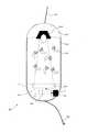
次に図2を参照して、本発明の一実施形態に係る撒餌容器100について説明する。図2に示す撒餌容器100は、本体101と、本体101の上方を覆う蓋111と、本体101の下方を覆う基底部112と、を備える。蓋111には、釣竿Rから伸びる道糸107の一端が取り付けられる。基底部112の下端にはハリスが取り付けられており、このハリスの先端には釣り針108が取り付けられる。  Next, with reference to FIG. 2, thebait container 100 which concerns on one Embodiment of this invention is demonstrated. Thebait container 100 shown in FIG. 2 includes amain body 101, alid 111 that covers the upper portion of themain body 101, and abase portion 112 that covers the lower portion of themain body 101. One end of aroad thread 107 extending from the fishing rod R is attached to thelid 111. Harris is attached to the lower end of thebase 112, and afishing hook 108 is attached to the tip of this Harris.

本体101は、例えば中空の円筒形状に形成され、その中空の内部空間に撒餌105が収容される。撒餌105は、集魚効果のある任意の餌であり、例えば、オキアミ、魚肉のミンチ、煎り糠、及びさなぎ粉(粉状にしたカイコの死骸)等が用いられる。本体101は、例えば合成樹脂から成り、水中に撒餌を放出することができるように、その内部と外部とを連通する一以上の連通孔を有する。連通孔の位置、大きさ、数は限定的なものではなく、撒餌105の種類、釣りの対象とする魚種、及びこれら以外の要因により様々な位置に、様々な大きさ・数の連通孔を設けることができる。蓋111が本体101に対して開閉可能となるように蓋111を本体101に取り付け、水中で蓋111を開くことにより撒餌105を水中に放出してもよい。  Themain body 101 is formed in a hollow cylindrical shape, for example, and thebait 105 is accommodated in the hollow internal space. Thesalmon bait 105 is an arbitrary bait with a fish collecting effect, and for example, krill, fish mince, roasted rice cake, and pupa powder (pulverized silkworm carcass) are used. Themain body 101 is made of, for example, a synthetic resin, and has one or more communication holes that allow the inside and the outside to communicate with each other so that bait can be released into water. The position, size, and number of the communication holes are not limited, and communication holes of various sizes and numbers may be provided at various positions depending on the type of thebait 105, the fish species to be fishing, and other factors. Can be provided. Thelid 111 may be attached to themain body 101 so that thelid 111 can be opened and closed with respect to themain body 101, and thebait 105 may be released into the water by opening thelid 111 in water.

図2に示した撒餌容器100は、投光ユニット1022及び受光ユニット1021を含む残量検出ユニット102、信号処理部103、送信部104、並びに電源106を備える。残量検出ユニット102は、蓋111に設けられた投光ユニット1022と、基底部112に設けられた受光ユニット1021とを備え、撒餌容器100内における撒餌105の残量を検出することができる。信号処理部103は、後述するように、残量検出ユニット102により検出された撒餌105の残量を示す残量信号を生成し、送信部104は、残量信号を情報出力装置120に対して送信する。電源106は、残量検出ユニット102、信号処理部103、送信部104、及びこれら以外の電子部品に対して必要な電力を供給する。電源106は、例えば、小型のボタン電池、環境の温度差、振動、光エネルギーを電力に変換する環境発電型の電池、及びこれら以外の任意の電池であってもよい。これらの残量検出ユニット102、信号処理部103、送信部104、及び電源106は
、漏電が起きないように適切な防水処理が施されている。
Thebait container 100 shown in FIG. 2 includes a remaining amount detection unit 102 including alight projecting unit 1022 and alight receiving unit 1021, asignal processing unit 103, atransmission unit 104, and apower source 106. The remaining amount detection unit 102 includes alight projecting unit 1022 provided on thelid 111 and alight receiving unit 1021 provided on thebase 112, and can detect the remaining amount of thefood 105 in thefood container 100. As will be described later, thesignal processing unit 103 generates a remaining amount signal indicating the remaining amount of thebait 105 detected by the remaining amount detecting unit 102, and the transmittingunit 104 sends the remaining amount signal to theinformation output device 120. Send. Thepower source 106 supplies necessary power to the remaining amount detection unit 102, thesignal processing unit 103, thetransmission unit 104, and other electronic components. Thepower source 106 may be, for example, a small button battery, an environmental temperature difference, vibration, an energy generation type battery that converts light energy into electric power, and any other battery. The remaining amount detection unit 102, thesignal processing unit 103, thetransmission unit 104, and thepower source 106 are appropriately waterproofed so as to prevent leakage.

受光ユニット1021は、基底部112に投光ユニット1022と対向するように設けられ、投光ユニット1022から発せされ本体101の内部空間を経て伝達された光を受光するように構成される。投光ユニット1022は、例えば、発光ダイオード(LED)であり、所定の帯域の光を発することができる。投光ユニット1022は、水中での透過性が高く、且つ、撒餌105によって遮断されやすい(減衰されやすい)帯域の光を発するように構成される。投光ユニット1022から発せられる光は、例えば、可視光、赤外光、又はこれら以外の可視光帯域近傍の周波数帯の光であってもよい。  Thelight receiving unit 1021 is provided on the base 112 so as to face thelight projecting unit 1022, and is configured to receive light emitted from thelight projecting unit 1022 and transmitted through the internal space of themain body 101. Thelight projecting unit 1022 is, for example, a light emitting diode (LED), and can emit light in a predetermined band. Thelight projecting unit 1022 is configured to emit light in a band that has high permeability in water and is easily blocked (damped easily) by thebait 105. The light emitted from thelight projecting unit 1022 may be, for example, visible light, infrared light, or other light in a frequency band near the visible light band.

受光ユニット1021は、フォトダイオード等の光電変換素子を備える。この光電変換素子は、例えば、公知の硫化カドミウムセルである。受光ユニット1021の光電変換素子は、受光量に応じた量の電荷を発生させ、この発生させた電荷の量に応じた電気信号(例えば電圧値)を読み出して出力信号として出力することができる。受光ユニット1021において十分な光量の光を受光できるようにするために、投光ユニット1022には集光レンズを設けてもよい。また、撒餌容器100の周囲からの環境光が受光ユニット1021に入射してノイズが発生しないようにするため、本体101に光を透過しない遮光部材を取り付けたり、または、光を透過しない合成樹脂から本体101を形成してもよい。  Thelight receiving unit 1021 includes a photoelectric conversion element such as a photodiode. This photoelectric conversion element is, for example, a known cadmium sulfide cell. The photoelectric conversion element of thelight receiving unit 1021 can generate an amount of electric charge corresponding to the amount of received light, read an electric signal (for example, a voltage value) corresponding to the amount of the generated electric charge, and output it as an output signal. In order that thelight receiving unit 1021 can receive a sufficient amount of light, thelight projecting unit 1022 may be provided with a condenser lens. Further, in order to prevent ambient light from the surroundings of thebait container 100 from entering thelight receiving unit 1021 and generating noise, a light shielding member that does not transmit light is attached to themain body 101, or a synthetic resin that does not transmit light is used. Themain body 101 may be formed.

以上のように、受光ユニット1021が投光ユニット1022と対向するように設けられ、投光ユニット1022から本体101の内部空間を経て伝達された光を受光するように構成されているため、本体101の内部空間に残っている撒餌105の量が多い場合には、撒餌105によって投光ユニット1022からの光が遮断され、受光ユニット1021から出力される電圧が小さくなる。撒餌105が水中に放出されて撒餌容器100内に残存する撒餌105の量が少なくなると、受光ユニット1021への入射光の光量が増え、受光ユニット1021から出力される電圧が大きくなる。撒餌容器100における撒餌105の残量と受光ユニット1021への入射光の光量(すなわち、残検出ユニット102の出力)との関係は、例えば、図3に示すグラフのように表される。図3のグラフは、撒餌容器100内における撒餌105の残量に対して受光ユニット1021への入射光の光量が単調に減少することを示している。このように、受光ユニット1021の出力によって、本体101内の撒餌105の残量を検出することができる。  As described above, thelight receiving unit 1021 is provided so as to face thelight projecting unit 1022, and is configured to receive light transmitted from thelight projecting unit 1022 through the internal space of themain body 101. When the amount of thebait 105 remaining in the interior space is large, the light from thelight projecting unit 1022 is blocked by thebait 105 and the voltage output from thelight receiving unit 1021 is reduced. When thebait 105 is discharged into the water and the amount of thebait 105 remaining in thebait container 100 decreases, the amount of incident light to thelight receiving unit 1021 increases and the voltage output from thelight receiving unit 1021 increases. The relationship between the remaining amount of thebait 105 in thebait container 100 and the amount of incident light to the light receiving unit 1021 (that is, the output of the remaining detection unit 102) is expressed as a graph shown in FIG. 3, for example. The graph of FIG. 3 shows that the amount of light incident on thelight receiving unit 1021 monotonously decreases with respect to the remaining amount of thebait 105 in thebait container 100. Thus, the remaining amount of thebait 105 in themain body 101 can be detected by the output of thelight receiving unit 1021.

本発明の一実施形態においては、投光ユニット1022を省略することができる。この場合、受光ユニット1021は、本体101を経て入射する環境光の光量に応じた電気信号を出力する。このように、投光ユニット1022を省略しても、受光ユニット1021の出力によって、本体101内の撒餌105の残量を検出することができる。  In one embodiment of the present invention, thelight projecting unit 1022 can be omitted. In this case, thelight receiving unit 1021 outputs an electrical signal corresponding to the amount of ambient light incident through themain body 101. Thus, even if thelight projecting unit 1022 is omitted, the remaining amount of thebait 105 in themain body 101 can be detected by the output of thelight receiving unit 1021.

信号処理部103は、残量検出ユニット102から出力された電気信号に基づいて、撒餌容器100内の撒餌の残量を示す残量信号を生成する。一実施形態において、信号処理部103は、所定時間ごとに残量検出ユニット102から出力された電気信号(例えば電圧)の値を所定の閾値と比較し、その比較結果に応じて、撒餌容器100内の撒餌105の残量を判別する。一実施形態においては、図3に示すように、信号処理部103は、残量検出ユニット102からの出力信号に応じて、撒餌105の残量を「多」、「中」、「少」の3段階に判定し、その判定結果を表す残量信号を生成することができる。図3に示した例では、信号処理部103は、残量検出ユニット102の出力信号の値(例えば電圧値)を所定の閾値T1及びT2と比較し、その出力信号の値が閾値T1よりも小さい場合には残量を「多」と判定し、閾値T1以上で閾値T2よりも小さい場合には残量を「中」と判定し、閾値T2以上の場合には残量を「小」と判定する。撒餌105の残量は、必要に応じて、何段階に判定してもよく、例えば、2段階、5段階、10段階のいずれに判定してもよい。  Thesignal processing unit 103 generates a remaining amount signal indicating the remaining amount of food in thefood container 100 based on the electrical signal output from the remaining amount detection unit 102. In one embodiment, thesignal processing unit 103 compares the value of the electrical signal (for example, voltage) output from the remaining amount detection unit 102 at predetermined time intervals with a predetermined threshold value, and according to the comparison result, thefood container 100 The remaining amount of thebait 105 is determined. In one embodiment, as illustrated in FIG. 3, thesignal processing unit 103 sets the remaining amount of thebait 105 to “high”, “medium”, and “low” in accordance with the output signal from the remaining amount detection unit 102. It is possible to make a determination in three stages and generate a remaining amount signal representing the determination result. In the example shown in FIG. 3, thesignal processing unit 103 compares the value (for example, voltage value) of the output signal of the remaining amount detection unit 102 with predetermined threshold values T1 and T2, and the value of the output signal is higher than the threshold value T1. If it is small, the remaining amount is determined as “many”. If the threshold value is equal to or greater than the threshold value T1 and smaller than the threshold value T2, the remaining amount is determined as “medium”. judge. The remaining amount of thebait 105 may be determined in any number of stages as necessary, and may be determined in any of two stages, five stages, and ten stages, for example.

また、信号処理部103は、残量信号によって搬送波を変調して変調波を生成し、この変調波を送信部104から水中に送信する。残量信号の変調は、様々なアナログ変調又はデジタル変調を用いて行われる。アナログ変調を用いる場合には、残量信号は、変調前にD/A変換される。残量信号を変調するために、公知の様々な変調方式を用いることができる。例えば、振幅変調、周波数変調、位相変調、及びこれら以外の様々な変調方式を用いることができる。  Further, thesignal processing unit 103 generates a modulated wave by modulating the carrier wave with the remaining amount signal, and transmits the modulated wave from the transmittingunit 104 to the water. The remaining amount signal is modulated using various analog modulations or digital modulations. When analog modulation is used, the remaining amount signal is D / A converted before modulation. Various known modulation schemes can be used to modulate the remaining amount signal. For example, amplitude modulation, frequency modulation, phase modulation, and various other modulation methods can be used.

残量信号を搬送するために、様々な搬送波、例えば、様々な帯域の音波や電磁波を用いることができる。一実施形態においては、超音波が搬送波として用いられる。他の実施形態においては、可視光帯域の電磁波が搬送波として用いられる。音波は電磁波と比較して水中での減衰率が小さいため、音波を搬送波として用いることにより、残量信号を効率的に情報出力装置120へ伝送することができる。また、可視光は、他の帯域の電磁波と比較して、水中での減衰率が著しく小さいことが分かっている(例えば、海洋音響学会編「海洋音響の基礎と応用」成山堂書店を参照。)ので、可視光領域の電磁波を用いることにより、残量信号を効率的に情報出力装置120へ伝送することができる。  To carry the remaining amount signal, various carrier waves, for example, sound waves and electromagnetic waves of various bands can be used. In one embodiment, ultrasound is used as the carrier wave. In other embodiments, an electromagnetic wave in the visible light band is used as a carrier wave. Since sound waves have a smaller attenuation rate in water than electromagnetic waves, the remaining amount signal can be efficiently transmitted to theinformation output device 120 by using sound waves as carrier waves. Visible light has been found to have a significantly lower attenuation rate in water than electromagnetic waves in other bands (see, for example, “The Basics and Applications of Ocean Acoustics” edited by the Ocean Acoustics Society of Nariyamado Shoten. Therefore, the remaining amount signal can be efficiently transmitted to theinformation output device 120 by using the electromagnetic wave in the visible light region.

残量信号により超音波を周波数変調して得られた音響信号が撒餌容器100から送信される場合、当該音響信号は、例えば、図4に示すように変化する。図4は、撒餌容器100を水中に投入してからの経過時間と、残量信号を周波数変調して得られた音響信号との関係を表す模式的な図である。図4の横軸は、撒餌容器100を水中に投入してからの経過時間を表し、縦軸は音響信号の振幅を表す。図4の例においては、周波数変調を用いているため、音響信号の振幅は一定である。撒餌容器100が水中へ投入された当初は、残存している撒餌105の量が多いため、撒餌105の残量が多いことを示す残量信号によって搬送波は周波数f1に変調される。撒餌容器100が水中へ投入されてからしばらく経つと、撒餌105が減少し、残量が中程度であることを表す残量信号が検出されるようになる。この場合、搬送波は、残量が中程度であることを表す残量信号によって、周波数f1よりも高い周波数f2に変調される。さらに時間が経過すると、撒餌105の残量が少ないことを示す残量信号が検出され、搬送波は、この残量が少ないことを示す残量信号によって周波数f2よりも高い周波数f3に変調される。図4では、変調後の搬送波が間欠的に送信される場合を示しているが、搬送波は連続して送信されてもよい。  When the acoustic signal obtained by frequency-modulating the ultrasonic wave with the remaining amount signal is transmitted from thebait container 100, the acoustic signal changes as shown in FIG. 4, for example. FIG. 4 is a schematic diagram showing the relationship between the elapsed time since thebait container 100 was put into water and the acoustic signal obtained by frequency-modulating the remaining amount signal. The horizontal axis of FIG. 4 represents the elapsed time after feeding thebait container 100 into water, and the vertical axis represents the amplitude of the acoustic signal. In the example of FIG. 4, since the frequency modulation is used, the amplitude of the acoustic signal is constant. Since the amount of the remainingbait 105 is large at the beginning when thebait container 100 is put into the water, the carrier wave is modulated to the frequency f1 by the remaining amount signal indicating that the remaining amount of thebait 105 is large. After a while after thebait container 100 is put into the water, thebait 105 is reduced and a remaining amount signal indicating that the remaining amount is medium is detected. In this case, the carrier wave is modulated to a frequency f2 higher than the frequency f1 by a remaining amount signal indicating that the remaining amount is medium. When the time further elapses, a remaining amount signal indicating that the remaining amount of thebait 105 is small is detected, and the carrier wave is modulated to a frequency f3 higher than the frequency f2 by the remaining amount signal indicating that the remaining amount is small. Although FIG. 4 shows a case where the modulated carrier wave is transmitted intermittently, the carrier wave may be transmitted continuously.

送信部104は、信号処理部103によって変調された残量信号を送信するように構成される。例えば、搬送波が超音波の場合には、送信部104は圧電素子を備え、信号処理部103からの残量信号に基づいて当該圧電素子を振動させることにより音響信号を生成し、この音響信号を水中へ送信することができる。搬送波として電磁波を用いる場合には、送信部104は、電力増幅器とアンテナとを備え、信号処理部103からの残量信号を当該電力増幅器で増幅し、増幅した変調信号を当該アンテナから放射するように構成される。  Thetransmission unit 104 is configured to transmit the remaining amount signal modulated by thesignal processing unit 103. For example, when the carrier wave is an ultrasonic wave, thetransmission unit 104 includes a piezoelectric element, generates an acoustic signal by vibrating the piezoelectric element based on the remaining amount signal from thesignal processing unit 103, and outputs the acoustic signal. Can be sent underwater. When electromagnetic waves are used as the carrier wave, thetransmission unit 104 includes a power amplifier and an antenna, amplifies the residual signal from thesignal processing unit 103 with the power amplifier, and radiates the amplified modulation signal from the antenna. Configured.

送信部104から送信された信号は、情報出力装置120の受信部121で受信される。超音波に変調された残量信号を受信(受波)する場合には、受信部121として、受信した超音波を電気信号に変換するハイドロフォンを用いることができる。残量信号が電磁波を利用した無線通信により伝送される場合には、受信部121は、アンテナで受信した受信波を復調部122に出力する。また、可視光に変調された残量信号を受信する場合には、受信部121として、受光センサーを用いることができる。  The signal transmitted from thetransmission unit 104 is received by thereception unit 121 of theinformation output device 120. When receiving (receiving) a remaining amount signal modulated into an ultrasonic wave, a hydrophone that converts the received ultrasonic wave into an electrical signal can be used as the receivingunit 121. When the remaining amount signal is transmitted by wireless communication using electromagnetic waves, thereception unit 121 outputs the received wave received by the antenna to thedemodulation unit 122. When receiving the remaining amount signal modulated into visible light, a light receiving sensor can be used as the receivingunit 121.

復調部122は、受信部121から出力される受信信号を必要に応じて増幅し、信号処理部103での変調処理に応じた復調処理を行って残量信号を得る。例えば、復調部122によって周波数f1の信号が検出された場合には撒餌105の残量が多いと判定し、周
波数f2の信号が得られた場合には撒餌105の残量が中程度と判定し、周波数f3の信号が得られた場合には撒餌105の残量が少ないと判定することができる。復調部122は、撒餌105の残量の判定結果に応じた信号(つまり、復号された残量信号)を出力部123に出力する。
Thedemodulation unit 122 amplifies the reception signal output from thereception unit 121 as necessary, and performs demodulation processing according to the modulation processing in thesignal processing unit 103 to obtain a residual signal. For example, if thedemodulator 122 detects a signal with the frequency f1, it determines that the remaining amount of thebait 105 is large, and if a signal with the frequency f2 is obtained, determines that the remaining amount of thebait 105 is medium. When the signal of the frequency f3 is obtained, it can be determined that the remaining amount of thebait 105 is small. Thedemodulation unit 122 outputs a signal (that is, a decoded remaining amount signal) corresponding to the determination result of the remaining amount of thebait 105 to theoutput unit 123.

出力部123は、復調部122からの復調された残量信号に基づいて、撒餌容器100に残存している撒餌105の量を釣り人に伝達するように構成される。本発明の一実施形態に係る出力部123は、例えば、復調部122からの出力信号に基づいて生成された表示画面を生成するモニタを備える。このモニタは、液晶モニタ等の任意のモニタである。このモニタには、例えば、復調部122によって復調された残量信号に基づいて、撒餌容器100に残存している撒餌105の残量が表示される。例えば、復調部122によって復調された残量信号が撒餌容器100における撒餌105の残量が多いことを示す場合には、その旨の表示(例えば、「撒餌残量:多」)を含む表示画面が当該モニタに表示される。出力部123は、最新の残量だけでなく、残量の時間経過をグラフ形式で示してもよい。  Theoutput unit 123 is configured to transmit the amount of thebait 105 remaining in thebait container 100 to the angler based on the demodulated remaining amount signal from thedemodulator 122. Theoutput unit 123 according to the embodiment of the present invention includes, for example, a monitor that generates a display screen generated based on an output signal from thedemodulation unit 122. This monitor is an arbitrary monitor such as a liquid crystal monitor. On this monitor, for example, the remaining amount ofbait 105 remaining in thebait container 100 is displayed based on the remaining amount signal demodulated by thedemodulator 122. For example, when the remaining amount signal demodulated by thedemodulation unit 122 indicates that the remaining amount of thebait 105 in thebait container 100 is large, a display screen including a display to that effect (for example, “remaining amount of bait: many”) Is displayed on the monitor. Theoutput unit 123 may indicate not only the latest remaining amount but also the remaining amount of time in a graph format.

また、本発明の他の実施形態に係る出力部123は、警告灯の色や発光パターンによって撒餌105の残量を釣り人に伝達することができる。この警告灯は、例えば、LEDを備える。この場合、出力部123は、例えば、青、白、赤でそれぞれ発光する3つのLEDを備え、残量が多い場合には青のLED、中程度の場合には白のLED、残量が少ない場合には赤のLEDを発光させることにより、釣り人に対して撒餌105の残量を通知することができる。また、LEDの点滅周期と撒餌105の残量を対応させることにより撒餌105の残量を釣り人に通知することもできる。  Moreover, theoutput part 123 which concerns on other embodiment of this invention can transmit the residual amount of thebait 105 to a angler with the color and light emission pattern of a warning light. This warning light includes, for example, an LED. In this case, theoutput unit 123 includes, for example, three LEDs that emit light in blue, white, and red, respectively. When the remaining amount is large, the blue LED is used. When the remaining amount is medium, the white LED is small. In this case, the remaining amount of thebait 105 can be notified to the angler by causing the red LED to emit light. Further, the angler can be notified of the remaining amount of thebait 105 by associating the blinking period of the LED with the remaining amount of thebait 105.

また、本発明の他の実施形態に係る出力部123は、音響信号(例えば、ブザー)の単位時間あたりの発信回数や音量によって、撒餌105の残量を釣り人に伝達することができる。この場合、出力部123は、例えば、残量が多いほどブザーの単位時間あたりの発信回数を多くしたり、ブザーの音量を大きくするように構成される。  Moreover, theoutput part 123 which concerns on other embodiment of this invention can transmit the residual amount of thebait 105 to a angler by the frequency | count of transmission and the sound volume per unit time of an acoustic signal (for example, buzzer). In this case, for example, theoutput unit 123 is configured to increase the number of transmissions per unit time of the buzzer or increase the volume of the buzzer as the remaining amount increases.

以上説明した撒餌残量検出システムを用いる場合、まず、撒餌容器100に所定量の撒餌105が充填される。釣り人は、他の仕掛けとともに撒餌容器100を釣糸に取り付けて水中に投入する。撒餌容器100が水中に投入されると、内部の撒餌105が徐々に水中に放出される。撒餌容器100は、その内部の残存している撒餌105の残量を検出し、検出した撒餌の残量を示す残量信号で搬送波を変調し、この変調された搬送波を送信する。情報出力装置120は、撒餌容器100の送信信号を受信し、この受信した信号を復調及び復号することにより残量信号を得る。そして、この残量信号に基づいて、撒餌容器100に残存する撒餌105の残量が液晶モニタやブザー等により釣り人に通知される。  In the case where the above-described system for detecting the amount of remaining bait is used, first, thebait container 100 is filled with a predetermined amount ofbait 105. The angler attaches thebait container 100 to the fishing line together with other devices and throws it into the water. When thebait container 100 is thrown into the water, theinternal bait 105 is gradually released into the water. Thebait container 100 detects the remaining amount of the remainingbait 105 therein, modulates a carrier wave with a remaining amount signal indicating the detected remaining bait amount, and transmits the modulated carrier wave. Theinformation output device 120 receives the transmission signal of thebait container 100, and obtains a remaining amount signal by demodulating and decoding the received signal. Based on the remaining amount signal, the angler is notified of the remaining amount of thebait 105 remaining in thebait container 100 by a liquid crystal monitor or a buzzer.

以上のように、本発明の実施形態によって、釣り人は、撒餌容器100に残存している撒餌105の残量を、撒餌容器100を引き上げることなく正確に把握することができる。また、釣り人は、撒餌105の残量が少なくなったことを出力部123からの出力(画面表示や音響信号)によって知ることができるので、誤ったタイミングで撒餌容器100を引き上げなくとも済む。上述したように、従来の撒餌容器では、しゃくり回数等に基づいて撒餌の残量を推定しているに過ぎなかったため、実際には十分な量の撒餌が残っているにもかかわらずに撒餌容器を引き上げたり、逆に、撒餌が空になったまま撒餌容器を水中にしばらくの間放置してしまうこともあった。本発明の実施形態によれば、撒餌容器における撒餌の残量を実際に検出しているので、水流等の環境の影響によらずに、撒餌の残量を正確に把握することができる。これにより、撒餌の残量が少ないと誤認して仕掛けを引き上げたり、撒餌が十分に残っていると誤認して空の撒餌容器を放置することが避けられるので、釣果を改善することが期待される。特に、仕掛けの回収に時間がかかる釣り方
をする場合(例えば、撒餌容器100が深い棚へ投入される場合や仕掛けを遠投する場合)に、余分な引き上げを行わないことによる釣果の改善効果が大きく期待できる。また、撒餌容器100から情報出力装置120への残量信号の送信周期(単位時間あたりに何度送信されるか)を適切に調整することにより、釣り人は、遅滞なく撒餌残量が少なくなったことを把握することができる。
As described above, according to the embodiment of the present invention, the angler can accurately grasp the remaining amount of thebait 105 remaining in thebait container 100 without lifting thebait container 100. Moreover, since the angler can know that the remaining amount of thebait 105 has decreased by the output (screen display or acoustic signal) from theoutput unit 123, it is not necessary to pull up thebait container 100 at an incorrect timing. As described above, in the conventional bait container, since the remaining amount of bait is only estimated based on the number of times of scooping, etc., the bait container is actually used even though a sufficient amount of bait remains. Or, conversely, the bait container was left in the water for a while while the bait was empty. According to the embodiment of the present invention, since the remaining amount of the bait in the bait container is actually detected, the remaining amount of the bait can be accurately grasped regardless of the influence of the environment such as the water flow. As a result, it is possible to avoid mistaking that the amount of bait is low and pulling up the mechanism, or leaving the empty bait container unattended when there is enough bait remaining, so it is expected to improve fishing results. The In particular, in the case of fishing that takes time to collect the device (for example, when thebait container 100 is put into a deep shelf or when the device is thrown long), the effect of improving the fishing results by not performing extra pulling Can be expected greatly. Further, by appropriately adjusting the transmission period of the remaining amount signal from thebait container 100 to the information output device 120 (how many times it is transmitted per unit time), the angler can reduce the remaining amount of bait without delay. Can be understood.

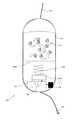
次に、図5を参照して、本発明の他の実施形態に係る撒餌容器について説明する。図5は、本発明の他の実施形態に係る撒餌容器200を概略的に示す図である。撒餌容器200は、撒餌105の残量を検出する具体的な方法が撒餌容器100と異なっている。  Next, with reference to FIG. 5, the bait container which concerns on other embodiment of this invention is demonstrated. FIG. 5 is a diagram schematically showing abait container 200 according to another embodiment of the present invention. Thebait container 200 is different from thebait container 100 in a specific method for detecting the remaining amount of thebait 105.

図5に示すように、撒餌容器200は、位置検出センサ2021、プローブ2022、検出用磁石2023、及びバネ2024を備える。プローブ2022は、例えば合成樹脂から成る板状又は棒状の部材であり、本体101又は蓋111に、軸2025の回りで枢動可能に軸支される。プローブ2022の先端には永久磁石2023が取り付けられている。永久磁石2023は、プローブ2022とともに、軸2025の回りを回転する。  As shown in FIG. 5, thebait container 200 includes aposition detection sensor 2021, aprobe 2022, adetection magnet 2023, and aspring 2024. Theprobe 2022 is a plate-like or rod-like member made of, for example, a synthetic resin, and is pivotally supported by themain body 101 or thelid 111 so as to be pivotable around theaxis 2025. Apermanent magnet 2023 is attached to the tip of theprobe 2022. Thepermanent magnet 2023 rotates around theaxis 2025 together with theprobe 2022.

位置検出センサ2021は、例えば、基底部112の永久磁石2023の軌道上に設けられる。位置検出センサ2021は、磁気型の近接センサであり、例えば、ホール素子等の磁気センサを備えている。位置検出センサ2021は、永久磁石2023の磁界を検出することにより、プローブ2022の位置に応じた電気信号を信号処理部103に出力することができる。本実施形態における位置検出センサ2021は、磁気型の近接センサ以外にも、公知の様々な位置検出センサ又は近接センサを用いて実現される。例えば、位置検出センサ2021は、プローブ2022との間の電気抵抗の変化を検出する電気抵抗型センサ、プローブ2022との間の静電容量の変化を検出する静電容量型センサ、光学式センサ、高周波発振型の近接センサ、又はこれら以外の各種の公知の位置検出センサであってもよい。  Theposition detection sensor 2021 is provided on the track of thepermanent magnet 2023 of thebase 112, for example. Theposition detection sensor 2021 is a magnetic proximity sensor and includes, for example, a magnetic sensor such as a Hall element. Theposition detection sensor 2021 can output an electric signal corresponding to the position of theprobe 2022 to thesignal processing unit 103 by detecting the magnetic field of thepermanent magnet 2023. Theposition detection sensor 2021 in the present embodiment is realized using various known position detection sensors or proximity sensors in addition to the magnetic proximity sensor. For example, theposition detection sensor 2021 is an electric resistance type sensor that detects a change in electric resistance with theprobe 2022, a capacitance type sensor that detects a change in capacitance with theprobe 2022, an optical sensor, It may be a high-frequency oscillation type proximity sensor or various known position detection sensors other than these.

永久磁石2023は、バネ2024によって、常時、位置検出センサ2021の方向へ付勢されている。バネ2024からプローブ2022へ付勢される力は、バネ2024によって付勢されたプローブ2022によって撒餌105が撒餌容器100から押し出されない程度の力に調整される。永久磁石2023は、反時計回りに回転することにより位置検出センサ2021に接近し、時計回りに回転することにより位置検出センサ2021から離れる。  Thepermanent magnet 2023 is always biased toward theposition detection sensor 2021 by aspring 2024. The force biased from thespring 2024 to theprobe 2022 is adjusted to a force that prevents thebait 105 from being pushed out of thebait container 100 by theprobe 2022 biased by thespring 2024. Thepermanent magnet 2023 approaches theposition detection sensor 2021 by rotating counterclockwise, and moves away from theposition detection sensor 2021 by rotating clockwise.

当該撒餌容器200によれば、十分な量の撒餌105が撒餌容器200内に残存しているときには、撒餌105からプローブ2022に作用する軸2025の回りで時計回り方向の圧力がバネ2024の反時計回り方向の付勢力に勝って、プローブ2022は時計回り方向の端(図5の左端)に位置する。撒餌105が放出されて、撒餌容器200内の残量が少なくなるにつれて、バネの反時計回り方向の付勢力が優勢となり、プローブ2022は徐々に反時計回り方向に移動し、位置検出センサ2021に近づく。このように、プローブ2022の位置は撒餌105の残量に応じて決まるので、プローブ2022の位置を検出することにより撒餌105の残量を検出することができる。信号処理部103は、位置検出センサ2021からの出力信号に基づいて撒餌105の残量を算出し、当該残量を表す残量信号を生成する。このようにして生成された残量信号は、送信部104から情報出力装置120に送信される。情報出力装置120は、受信した残量信号に基づいて、撒餌容器200内の撒餌105の残量を釣り人に通知することができる。  According to thebait container 200, when a sufficient amount ofbait 105 remains in thebait container 200, the clockwise pressure around theaxis 2025 acting on theprobe 2022 from thebait 105 is counterclockwise of thespring 2024. Theprobe 2022 is positioned at the end in the clockwise direction (the left end in FIG. 5) overcoming the biasing force in the rotation direction. As thebait 105 is released and the remaining amount in thebait container 200 decreases, the biasing force of the spring in the counterclockwise direction becomes dominant, and theprobe 2022 gradually moves in the counterclockwise direction to theposition detection sensor 2021. Get closer. Thus, since the position of theprobe 2022 is determined according to the remaining amount of thebait 105, the remaining amount of thebait 105 can be detected by detecting the position of theprobe 2022. Thesignal processing unit 103 calculates the remaining amount of thebait 105 based on the output signal from theposition detection sensor 2021, and generates a remaining amount signal representing the remaining amount. The remaining amount signal generated in this way is transmitted from thetransmission unit 104 to theinformation output device 120. Theinformation output device 120 can notify the angler of the remaining amount of thebait 105 in thebait container 200 based on the received remaining amount signal.

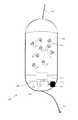
次に、図6を参照して、本発明のさらに他の実施形態に係る撒餌容器について説明する。図6は、本発明のさらに他の実施形態に係る撒餌容器300を概略的に示す図である。撒餌容器300は、撒餌105の残量を検出する具体的な方法が撒餌容器100と異なっ
ている。
Next, a bait container according to still another embodiment of the present invention will be described with reference to FIG. FIG. 6 is a view schematically showing abait container 300 according to still another embodiment of the present invention. Thebait container 300 is different from thebait container 100 in a specific method for detecting the remaining amount of thebait 105.

図6に示すように、撒餌容器300は、圧力検出センサ3021、バネ3022、及びピストン3023を備える。ピストン3023は、例えば合成樹脂製の円板状のメッシュから成る。当該円板状のピストンは、その外周が本体101の内周よりも一回り小さな円形に形成される。ピストン3023のメッシュの目は、撒餌105が通過できない程度の粗さに形成される。ピストン3023の下面の中心付近には、バネが3022が取り付けられており、このバネ3022によって常時上方に付勢されている。また、ピストン3023の上方には、撒餌105が充填されているため、この撒餌105からピストン3023の上面に対して、撒餌105の量に応じた下向きの圧力が作用する。ピストン3023は、この撒餌105から作用する圧力及びバネ3022から受ける力に応じて、上下方向に移動することができる。  As shown in FIG. 6, thebait container 300 includes apressure detection sensor 3021, aspring 3022, and apiston 3023. Thepiston 3023 is made of, for example, a disc-shaped mesh made of synthetic resin. The disc-shaped piston is formed in a circular shape whose outer periphery is slightly smaller than the inner periphery of themain body 101. The mesh eyes of thepiston 3023 are formed with such a roughness that thebait 105 cannot pass through. Aspring 3022 is attached near the center of the lower surface of thepiston 3023, and is always biased upward by thespring 3022. Moreover, since thebait 105 is filled above thepiston 3023, a downward pressure corresponding to the amount of thebait 105 acts on the upper surface of thepiston 3023 from thebait 105. Thepiston 3023 can move in the vertical direction according to the pressure acting from thebait 105 and the force received from thespring 3022.

バネ3022の付勢力は、撒餌105がピストン3023のメッシュの間や、ピストン3023と本体101の内周面との間から押し出されない程度の力に調整される。バネ3022としては、線形ばねを用いることができる。バネ3022の他端は、圧力検出センサ3021に接続されているので、バネ3023は、ピストン3023の位置に応じた反力を圧力検出センサ3021に加えることができる。  The biasing force of thespring 3022 is adjusted to such a force that thebait 105 is not pushed out between the mesh of thepiston 3023 or between thepiston 3023 and the inner peripheral surface of themain body 101. A linear spring can be used as thespring 3022. Since the other end of thespring 3022 is connected to thepressure detection sensor 3021, thespring 3023 can apply a reaction force corresponding to the position of thepiston 3023 to thepressure detection sensor 3021.

圧力検出センサ3021としては、その表面にバネ3022が作用させる圧力を測定可能な任意の圧力検出センサを利用することができる。圧力検出センサ3021は、例えばひずみゲージを備えており、当該ひずみゲージに生じたひずみに応じた電気信号を信号処理部103に出力することができる。  As thepressure detection sensor 3021, any pressure detection sensor capable of measuring the pressure exerted by thespring 3022 on the surface can be used. Thepressure detection sensor 3021 includes, for example, a strain gauge, and can output an electrical signal corresponding to the strain generated in the strain gauge to thesignal processing unit 103.

当該撒餌容器300によれば、十分な量の撒餌105が撒餌容器200内に残存しているときには、撒餌105からピストン3023に加えられる圧力により、ピストン3023はその可動範囲の下端付近にあり、大きな応力が圧力検出センサ3021に加えられる。撒餌105が放出されて、撒餌容器200内の残量が少なくなるにつれて、バネ3022が撒餌105から受ける圧力が減少するので、その結果、圧力検出センサ3021に加えられる圧力も小さくなる。このように、圧力検出センサ3021にバネ3022から加えられる圧力は撒餌105の残量に応じて決まるので、圧力検出センサ3021からの出力信号に基づいて、信号処理部103において撒餌105の残量を検出し、当該検出した残量を表す残量信号が生成される。信号処理部103において生成された残量信号は、送信部104から情報出力装置120に送信される。情報出力装置120は、受信した残量信号に基づいて、撒餌容器200内の撒餌105の残量を釣り人に通知することができる。  According to thebait container 300, when a sufficient amount ofbait 105 remains in thebait container 200, thepiston 3023 is near the lower end of its movable range due to the pressure applied from thebait 105 to thepiston 3023. Stress is applied to thepressure detection sensor 3021. As thebait 105 is released and the remaining amount in thebait container 200 decreases, the pressure received by thespring 3022 from thebait 105 decreases. As a result, the pressure applied to thepressure detection sensor 3021 also decreases. Thus, since the pressure applied from thespring 3022 to thepressure detection sensor 3021 is determined according to the remaining amount of thebait 105, thesignal processing unit 103 determines the remaining amount of thebait 105 based on the output signal from thepressure detection sensor 3021. And a remaining amount signal representing the detected remaining amount is generated. The remaining amount signal generated in thesignal processing unit 103 is transmitted from thetransmission unit 104 to theinformation output device 120. Theinformation output device 120 can notify the angler of the remaining amount of thebait 105 in thebait container 200 based on the received remaining amount signal.

次に、図7を参照して、本発明のさらに他の実施形態に係る撒餌容器について説明する。図7は、本発明のさらに他の実施形態に係る撒餌容器400を概略的に示す図である。撒餌容器400は、撒餌105の残量を検出する具体的な方法が撒餌容器100と異なっている。  Next, a bait container according to still another embodiment of the present invention will be described with reference to FIG. FIG. 7 is a view schematically showing abait container 400 according to still another embodiment of the present invention. Thebait container 400 is different from thebait container 100 in a specific method for detecting the remaining amount of thebait 105.

図7に示すように、撒餌容器300は、濃度センサ402を備える。濃度センサ402は、その一部が本体101内部空間に露出しており、当該内部空間に存在する物質の濃度を測定可能に構成されている。濃度センサ402は、例えば、本体101の内部空間における塩分の濃度を測定する塩分濃度計である。撒餌容器400を淡水で使用し、撒餌105が塩分を含むものである場合などのように、撒餌容器400の使用環境と撒餌105とに塩分の濃度差がある場合は、濃度センサ402による本体101の内部空間の塩分濃度の測定結果に基づいて、本体101内の撒餌105の量を検出することができる。つまり、本体101内の塩分濃度が高い場合には撒餌105の残量が多く、塩分濃度が低い場合
には撒餌105の残量が少ないと判断することができる。このように、濃度センサ402からの出力信号に基づいて、信号処理部103において撒餌105の残量を検出し、当該検出した残量を表す残量信号が生成される。信号処理部103において生成された残量信号は、送信部104から情報出力装置120に送信される。情報出力装置120は、受信した残量信号に基づいて、撒餌容器200内の撒餌105の残量を釣り人に通知することができる。
As shown in FIG. 7, thebait container 300 includes aconcentration sensor 402. A part of theconcentration sensor 402 is exposed to the internal space of themain body 101, and is configured to be able to measure the concentration of a substance present in the internal space. Theconcentration sensor 402 is, for example, a salt concentration meter that measures the concentration of salt in the internal space of themain body 101. When there is a salt concentration difference between the environment in which thebait container 400 is used and thebait 105, such as when thebait container 400 is used in fresh water and thebait 105 contains salt, the inside of themain body 101 by theconcentration sensor 402 Based on the measurement result of the salinity concentration of the space, the amount of thebait 105 in themain body 101 can be detected. That is, it can be determined that when the salinity concentration in themain body 101 is high, the remaining amount of thebait 105 is large, and when the salinity concentration is low, the remaining amount of thebait 105 is small. As described above, thesignal processor 103 detects the remaining amount of thebait 105 based on the output signal from theconcentration sensor 402, and a remaining amount signal indicating the detected remaining amount is generated. The remaining amount signal generated in thesignal processing unit 103 is transmitted from thetransmission unit 104 to theinformation output device 120. Theinformation output device 120 can notify the angler of the remaining amount of thebait 105 in thebait container 200 based on the received remaining amount signal.

濃度センサ402が測定対象とする濃度は塩分の濃度に限られず、本体101の内部空間における濃度と撒餌容器400の使用環境(撒餌容器400が投入される水)とにおいて濃度が異なる様々な物質の濃度を測定することができる。例えば、濃度センサ402として、pHメータや糖度計を用いることができる。  The concentration to be measured by theconcentration sensor 402 is not limited to the salinity concentration, but various substances having different concentrations depending on the concentration in the internal space of themain body 101 and the environment in which thebait container 400 is used (water into which thebait container 400 is introduced). The concentration can be measured. For example, a pH meter or a saccharimeter can be used as theconcentration sensor 402.

次に、図8を参照して、本発明のさらに他の実施形態に係る撒餌容器について説明する。図8は、本発明のさらに他の実施形態に係る撒餌容器500を概略的に示す図である。撒餌容器500は、図2に示した撒餌容器100を変形したものであり、投光ユニット1022の配置が撒餌容器100と異なっている。すなわち、図8に示した撒餌容器500においては、投光ユニット1022が蓋111ではなく基底部112に設けられている。受光ユニット1021は、投光ユニット1022が発せられ本体101内の撒餌105で反射された光を受光するように構成される。  Next, a bait container according to still another embodiment of the present invention will be described with reference to FIG. FIG. 8 is a view schematically showing abait container 500 according to still another embodiment of the present invention. Thebait container 500 is a modification of thebait container 100 shown in FIG. 2, and the arrangement of thelight projecting unit 1022 is different from thebait container 100. That is, in thebait container 500 shown in FIG. 8, thelight projecting unit 1022 is provided not on thelid 111 but on thebase 112. Thelight receiving unit 1021 is configured to receive the light emitted from thelight projecting unit 1022 and reflected by thebait 105 in themain body 101.

以上のように、受光ユニット1021が投光ユニット1022から発生られた光の反射光を受光するように構成されているため、本体101の内部空間に残っている撒餌105の量が多い場合には、撒餌105によって投光ユニット1022からの光の多くが反射され、受光ユニット1021から出力される電圧が大きく。撒餌105が水中に放出されて撒餌容器100内に残存する撒餌105の量が少なくなると、受光ユニット1021への入射光の光量が減少し、受光ユニット1021から出力される電圧が小さくなる。したがって、受光ユニット1021の出力によって、本体101内の撒餌105の残量を検出することができる。  As described above, since thelight receiving unit 1021 is configured to receive the reflected light of the light generated from thelight projecting unit 1022, when the amount of thebait 105 remaining in the internal space of themain body 101 is large. Most of the light from thelight projecting unit 1022 is reflected by thebait 105, and the voltage output from thelight receiving unit 1021 is large. When thebait 105 is released into the water and the amount of thebait 105 remaining in thebait container 100 decreases, the amount of incident light to thelight receiving unit 1021 decreases, and the voltage output from thelight receiving unit 1021 decreases. Therefore, the remaining amount of thebait 105 in themain body 101 can be detected by the output of thelight receiving unit 1021.

このように、信号処理部103は、受光ユニット1021からの出力信号に基づいて撒餌105の残量を検出し当該検出した残量を表す残量信号を生成する。信号処理部103において生成された残量信号は、送信部104から情報出力装置120に送信される。情報出力装置120は、受信した残量信号に基づいて、撒餌容器200内の撒餌105の残量を釣り人に通知することができる。  As described above, thesignal processing unit 103 detects the remaining amount of thebait 105 based on the output signal from thelight receiving unit 1021 and generates a remaining amount signal indicating the detected remaining amount. The remaining amount signal generated in thesignal processing unit 103 is transmitted from thetransmission unit 104 to theinformation output device 120. Theinformation output device 120 can notify the angler of the remaining amount of thebait 105 in thebait container 200 based on the received remaining amount signal.

次に、図9を参照して、本発明のさらに他の実施形態に係る撒餌容器について説明する。図9は、本発明のさらに他の実施形態に係る撒餌容器600を概略的に示す図である。撒餌容器600は、検出用の超音波を発する水中マイク4021と、当該超音波の反射波を受波するハイドロフォン4022とを備える。水中マイク4021は、例えば、本体101の内部に向かって超音波を発波できるように、その配置及び向きが調整される。ハイドロフォン4022は、反射波を受けると電気信号を信号処理部103に出力することができる。  Next, with reference to FIG. 9, the bait container which concerns on further another embodiment of this invention is demonstrated. FIG. 9 is a view schematically showing abait container 600 according to still another embodiment of the present invention. Thebait container 600 includes anunderwater microphone 4021 that emits ultrasonic waves for detection, and ahydrophone 4022 that receives reflected waves of the ultrasonic waves. The arrangement and orientation of theunderwater microphone 4021 are adjusted so that, for example, ultrasonic waves can be emitted toward the inside of themain body 101. Thehydrophone 4022 can output an electric signal to thesignal processing unit 103 when receiving the reflected wave.

信号処理部103は、ハイドロフォン4022から出力された電気信号に基づいて、水中マイク4021からの検出用超音波の発波からその反射波を受けるまでの所要時間を計測することができる。本体101の内部空間に残っている撒餌105の量が多い場合には検出用超音波の発波からその反射波を受波するまでの時間が短く、一方、撒餌105が水中に放出されて撒餌容器100内に残存する撒餌105の量が少なくなると検出用超音波の発波からその反射波を受波するまでの時間が長くなる。したがって、信号処理部103は、検出用超音波の発波からその反射波を受波するまでの時間を所定の閾値と比較するこ
とにより、本体101の内部に残っている釣り餌105の残量を検出することができる。
Based on the electric signal output from thehydrophone 4022, thesignal processing unit 103 can measure the time required from receiving the detection ultrasonic wave from theunderwater microphone 4021 to receiving the reflected wave. When the amount of thebait 105 remaining in the internal space of themain body 101 is large, the time from receiving the detection ultrasonic wave to receiving the reflected wave is short. On the other hand, thebait 105 is released into the water and is consumed. When the amount of thebait 105 remaining in thecontainer 100 decreases, the time from receiving the detection ultrasonic wave to receiving the reflected wave becomes longer. Therefore, thesignal processing unit 103 compares the time from when the detection ultrasonic wave is generated to when the reflected wave is received with a predetermined threshold value, so that the remaining amount of thefishing bait 105 remaining in themain body 101 remains. Can be detected.

このように、ハイドロフォン4022からの出力信号に基づいて、信号処理部103において撒餌105の残量を検出し、当該検出した残量を表す残量信号が生成される。信号処理部103において生成された残量信号は、送信部104から情報出力装置120に送信される。情報出力装置120は、受信した残量信号に基づいて、撒餌容器200内の撒餌105の残量を釣り人に通知することができる。  As described above, thesignal processor 103 detects the remaining amount of thebait 105 based on the output signal from thehydrophone 4022, and a remaining amount signal indicating the detected remaining amount is generated. The remaining amount signal generated in thesignal processing unit 103 is transmitted from thetransmission unit 104 to theinformation output device 120. Theinformation output device 120 can notify the angler of the remaining amount of thebait 105 in thebait container 200 based on the received remaining amount signal.

次に、図10を参照して、本発明の一実施形態に係る餌検出装置について説明する。図10に示す餌検出装置700は、例えば中空の箱形に形成されている筐体701と、餌検出ユニット702と、信号処理部703と、送信部704と、電源706とを備える。餌検出ユニット702、信号処理部703、送信部704、及び電源706は、筐体701に収容されている。筐体701には防水処理が施されており、筐体701に収容されている各部材の漏電を防いでいる。餌検出ユニット702は、検出光を発する投光ユニット7021及び検出光の反射により生じる反射光を受ける受光ユニット7022を有する。  Next, a bait detection apparatus according to an embodiment of the present invention will be described with reference to FIG. Abait detection device 700 illustrated in FIG. 10 includes ahousing 701 formed in, for example, a hollow box shape, a bait detection unit 702, asignal processing unit 703, atransmission unit 704, and apower source 706. The bait detection unit 702, thesignal processing unit 703, thetransmission unit 704, and thepower source 706 are accommodated in thehousing 701. Thehousing 701 is waterproofed to prevent leakage of each member housed in thehousing 701. The bait detection unit 702 includes alight projecting unit 7021 that emits detection light and alight receiving unit 7022 that receives reflected light generated by reflection of the detection light.

筐体701は、ポリエチレン等の合成樹脂から形成される。筐体701の上部には、釣竿Rから伸びる道糸707の一端が取り付けられる。また、筐体701の下部にはハリス709が取り付けられており、このハリス709の先端には釣り針708が取り付けられる。釣り針708には、釣り餌705が取り付けられる。釣り餌705は、オキアミ、ゴカイ、イソメ等の生き餌、貝、イワシ、アジ等の魚介類、又は練り餌等の任意の釣り餌である。  Thehousing 701 is made of a synthetic resin such as polyethylene. One end of aroad line 707 extending from the fishing rod R is attached to the upper portion of thehousing 701. AHarris 709 is attached to the lower part of thehousing 701, and afishing hook 708 is attached to the tip of theHarris 709. Afishing bait 705 is attached to thefishing hook 708. Thefishing bait 705 is an arbitrary fishing bait such as a live bait such as a krill, a shellfish, an isome, a seafood such as a shellfish, a sardine, a horse mackerel, or a kneaded bait.

本発明の一実施形態において、餌検出装置700は、図1に示す撒餌容器100に代えて、または、撒餌容器100とともに用いられ、水中から情報出力装置120に対して情報を伝送できるように構成される。餌検出装置700を撒餌容器100とともに用いる場合には、餌検出装置700は、例えば、撒餌容器100と釣り針108との間に設けられる。  In one embodiment of the present invention, thebait detection device 700 is used in place of thebait container 100 shown in FIG. 1 or together with thebait container 100 and configured to transmit information to theinformation output device 120 from underwater. Is done. When thebait detection device 700 is used together with thebait container 100, thebait detection device 700 is provided between thebait container 100 and thefishing hook 108, for example.

一実施形態において、投光ユニット7021及び受光ユニット7022は、例えば、筐体701の下方に収容される。投光ユニット7021から放出される検出光及び受光ユニット7022へ向かう反射光を透過するように、筐体701の少なくとも一部は透明又は半透明に形成される。投光ユニット7021は、例えば、発光ダイオード(LED)であり、所定の帯域の光を発することができる。投光ユニット7021は、少なくとも釣り針708の周囲に検出光が照射されるように、その配置及び向きが調整される。投光ユニット7021は、例えば、集魚効果がある波長の光を発するように構成される。投光ユニット7021から発せられる光は、例えば、可視光、赤外光、又はこれら以外の可視光帯域近傍の周波数帯の光であってもよい。受光ユニット7022は、概ね受光ユニット1021と同様に構成される。つまり、受光ユニット7022は、受光量に応じた量の電荷を発生させ、この発生させた電荷の量に応じた電気信号(例えば電圧値)を読み出して、この読み出した電気信号を信号処理部703に出力することができる。  In one embodiment, thelight projecting unit 7021 and thelight receiving unit 7022 are accommodated below thehousing 701, for example. At least a part of thehousing 701 is formed to be transparent or translucent so as to transmit the detection light emitted from thelight projecting unit 7021 and the reflected light directed to thelight receiving unit 7022. Thelight projecting unit 7021 is, for example, a light emitting diode (LED), and can emit light in a predetermined band. The arrangement and orientation of thelight projecting unit 7021 are adjusted so that at least the periphery of thefishing hook 708 is irradiated with detection light. For example, thelight projecting unit 7021 is configured to emit light having a wavelength with a fish collection effect. The light emitted from thelight projecting unit 7021 may be, for example, visible light, infrared light, or other light in a frequency band near the visible light band. Thelight receiving unit 7022 is configured in substantially the same manner as thelight receiving unit 1021. That is, thelight receiving unit 7022 generates an amount of electric charge according to the amount of received light, reads an electric signal (for example, a voltage value) corresponding to the amount of the generated electric charge, and uses the read electric signal as asignal processing unit 703. Can be output.

このように、投光ユニット7021からの検出光が釣り針708の周囲に照射され、受光ユニット7022で当該検出光の反射光を受けて、その反射光の光量に応じた電気信号が出力される。したがって、釣り餌705が釣り針708に保持されている場合には釣り餌705によって反射された反射光が受光ユニット7022に入射されるので、釣り餌705が釣り針708から脱落した場合よりも、受光ユニット7022に入射する反射光の光量が大きい。  In this manner, the detection light from thelight projecting unit 7021 is irradiated around thefishing hook 708, the reflected light of the detection light is received by thelight receiving unit 7022, and an electrical signal corresponding to the amount of the reflected light is output. Therefore, when thefishing bait 705 is held by thefishing hook 708, the reflected light reflected by thefishing bait 705 is incident on thelight receiving unit 7022. Therefore, the light receiving unit is more than the case where thefishing bait 705 is dropped from thefishing hook 708. The amount of reflected light incident on 7022 is large.

信号処理部703は、餌検出ユニット702(受光ユニット7022)からの出力信号
に基づいて、釣り針708に釣り餌705が保持されているか否かを判定し、その判定結果に基づいて、釣り針708に釣り餌705が保持されているか否かを示す判定信号を生成する。一実施形態において、信号処理部703は、餌検出ユニット702から出力される電気信号の値が所定の閾値よりも大きい場合に釣り針708に釣り餌705が保持されていることを示す判定信号を生成する。このように、信号処理部703は、受光ユニット7022から出力される電気信号の値(電圧値)に基づいて、釣り針708に釣り餌705が保持されているか否かを検出することができる。信号処理部703は、任意のタイミングで判定信号を生成することができる。例えば、信号処理部703は、所定の周期(例えば5秒ごと)で受光ユニット7022から電気信号を読み出し、当該電気信号に基づいて判定信号を生成することができる。
Thesignal processing unit 703 determines whether or not thefishing bait 705 is held on thefishing hook 708 based on the output signal from the bait detection unit 702 (light receiving unit 7022), and based on the determination result, A determination signal indicating whether or not thefishing bait 705 is held is generated. In one embodiment, thesignal processing unit 703 generates a determination signal indicating that thefishing bait 705 is held on thefishing hook 708 when the value of the electrical signal output from the bait detection unit 702 is greater than a predetermined threshold. To do. Thus, thesignal processing unit 703 can detect whether thefishing bait 705 is held on thefishing hook 708 based on the value (voltage value) of the electrical signal output from thelight receiving unit 7022. Thesignal processing unit 703 can generate a determination signal at an arbitrary timing. For example, thesignal processing unit 703 can read an electrical signal from thelight receiving unit 7022 at a predetermined cycle (for example, every 5 seconds) and generate a determination signal based on the electrical signal.

信号処理部703は、判定信号によって搬送波を変調して変調波を生成し、この変調波を送信部104から水中に送信する。判定信号の変調は、様々なアナログ変調又はデジタル変調を用いて行われる。アナログ変調を用いる場合には、判定信号は、変調前にD/A変換される。判定信号を変調するために、公知の様々な変調方式を用いることができる。例えば、振幅変調、周波数変調、位相変調、及びこれら以外の様々な変調方式を用いることができる。例えば、周波数変調を用いる場合には、釣り針708に釣り餌705が保持されていることを示す判定信号によって搬送波が周波数f4に変調され、釣り針708に釣り餌705が保持されていない(脱落した)ことを示す判定信号によって搬送波が周波数f4に変調される。周波数f4及びf5は、互いに異なる周波数である。また、餌検出装置700が撒餌容器100とともに用いられる場合には、周波数f4及びf5は、周波数f1、f2、及びf3のいずれとも異なる周波数に設定される。  Thesignal processing unit 703 modulates the carrier wave with the determination signal to generate a modulated wave, and transmits the modulated wave from thetransmission unit 104 to the water. The modulation of the determination signal is performed using various analog modulations or digital modulations. When analog modulation is used, the determination signal is D / A converted before modulation. Various known modulation schemes can be used to modulate the determination signal. For example, amplitude modulation, frequency modulation, phase modulation, and various other modulation methods can be used. For example, when using frequency modulation, the carrier wave is modulated to the frequency f4 by the determination signal indicating that thefishing bait 705 is held on thefishing hook 708, and thefishing bait 705 is not held on the fishing hook 708 (dropped). The carrier wave is modulated to the frequency f4 by the determination signal indicating this. The frequencies f4 and f5 are different from each other. When thebait detection device 700 is used with thebait container 100, the frequencies f4 and f5 are set to frequencies different from any of the frequencies f1, f2, and f3.

送信部704は、信号処理部703によって変調された判定信号を送信するように構成される。一実施形態における送信部704は、上述した送信部104と同様に、判定信号で変調された超音波を送信できるように構成される。  Thetransmission unit 704 is configured to transmit the determination signal modulated by thesignal processing unit 703. Similar to thetransmission unit 104 described above, thetransmission unit 704 according to the embodiment is configured to transmit an ultrasonic wave modulated by the determination signal.

送信部704から送信された音響信号は、情報出力装置120の受信部121で受信される。次に、復調部122は、受信部121から出力される受信信号に信号処理部703での変調処理に応じた復調処理を行って判定信号を得る。これにより、例えば、復調部122によって周波数f4の信号が検出された場合には釣り針708に釣り餌705が保持されていると判定することができ、周波数f5の信号が検出された場合には釣り針708に釣り餌705が保持されていないと判定することができる。復調部122は、復調処理により得られた判定信号を出力部123に出力する。  The acoustic signal transmitted from thetransmission unit 704 is received by thereception unit 121 of theinformation output device 120. Next, thedemodulation unit 122 performs a demodulation process corresponding to the modulation process in thesignal processing unit 703 on the reception signal output from thereception unit 121 to obtain a determination signal. Thereby, for example, when the signal of the frequency f4 is detected by thedemodulator 122, it can be determined that thefishing bait 705 is held by thefishing hook 708, and when the signal of the frequency f5 is detected, the fishing hook It can be determined that thefishing bait 705 is not held at 708. Thedemodulation unit 122 outputs the determination signal obtained by the demodulation process to theoutput unit 123.

出力部123は、復調部122からの復調された判定信号に基づいて、釣り針に釣り餌が保持されているか否かを示す釣り餌検出情報を釣り人に伝達するように構成される。例えば、出力部123は、釣り針に釣り餌が保持されていることを示す情報、及び/又は、釣り針に釣り餌が保持されていないこと(釣り針から釣り餌が脱落したこと)を示す情報を釣り人に伝達するように構成される。出力部123のモニタには、例えば、復調部122によって復調された判定信号に基づいて、釣り針に釣り餌が保持されている旨の表示又は釣り針から釣り餌が脱落した旨の表示を含む表示画面が当該モニタに表示される。釣り餌検出情報は、モニタへの表示以外にも、ブザー、ダイオードの点滅等の任意の方法で釣り人に伝達され得る。  Based on the demodulated determination signal from thedemodulator 122, theoutput unit 123 is configured to transmit fishing bait detection information indicating whether or not the fishing bait is held on the fishhook to the angler. For example, theoutput unit 123 fishes information indicating that the fishing bait is held on the fishhook and / or information indicating that the fishing bait is not held on the fishhook (the fishing bait has been dropped from the fishhook). Configured to communicate to people. The monitor of theoutput unit 123 includes, for example, a display screen including a display indicating that the fishing bait is held on the fishing hook or a display indicating that the fishing bait has dropped from the fishing hook based on the determination signal demodulated by thedemodulation unit 122 Is displayed on the monitor. The fishing bait detection information can be transmitted to the angler by any method other than the display on the monitor, such as a buzzer or a blinking diode.

以上説明した餌検出装置700を使用する場合、まず、釣り人は、他の仕掛けとともに餌検出装置700を釣糸に取り付けて水中に投入する。餌検出装置700においては、所定の周期で判定信号が生成され、当該判定信号が情報出力装置120に伝送される。情報出力装置120は、餌検出装置700からの判定信号に基づいて、出力部123によって所定の表示を行ったり所定の音響信号を発生させたりすることにより、釣り餌が釣り針の
保持されているか否かを釣り人に通知することができる。
When using thebait detection device 700 described above, first, the angler attaches thebait detection device 700 to the fishing line together with other devices and throws it into the water. In thebait detection device 700, a determination signal is generated at a predetermined cycle, and the determination signal is transmitted to theinformation output device 120. Based on the determination signal from thebait detection device 700, theinformation output device 120 performs a predetermined display or generates a predetermined acoustic signal by theoutput unit 123, thereby determining whether the fishing bait is held by the fishhook. You can notify the angler.

以上のように、本発明の実施形態によって、釣り人は、餌検出装置700からの判定信号に基づいて釣り針に釣り餌が保持されているか否かを把握することができる。  As described above, according to the embodiment of the present invention, the angler can grasp whether or not the fishing bait is held on the fishing hook based on the determination signal from thebait detection device 700.

本発明の一実施形態において、餌検出装置700は、その比重が餌検出装置700が投入される環境(淡水や様々な濃度の海水)と等しくなるように、又は、実質的に等しくなるように構成される。一例として、餌検出装置700が淡水に投入される場合には、淡水の比重は約1.0であるため、餌検出装置700の比重は、約1.0、例えば、約0.8〜約1.2、約0.9〜約1.1、約0.95〜約1.05、又は約0.995〜約1.005となるように構成される。餌検出装置700が海水に投入される場合には、餌検出装置700の比重は、当該海水の比重と等しくなるように、又は、実質的に等しくなるように構成される。例えば、餌検出装置700が比重1.03の海水に投入される場合には、餌検出装置700の比重は、約1.03、例えば、約0.83〜約1.23、約0.93〜約1.13、約0.98〜約1.08、又は約1.025〜約1.035となるように構成される。  In one embodiment of the present invention, thebait detection device 700 has a specific gravity equal to or substantially equal to the environment (fresh water or seawater of various concentrations) into which thebait detection device 700 is introduced. Composed. As an example, when thebait detection device 700 is put into fresh water, the specific gravity of the fresh water is about 1.0, so the specific gravity of thebait detection device 700 is about 1.0, for example, about 0.8 to about 0.8. 1.2, about 0.9 to about 1.1, about 0.95 to about 1.05, or about 0.995 to about 1.005. When thebait detection apparatus 700 is thrown into seawater, the specific gravity of thebait detection apparatus 700 is configured to be equal to or substantially equal to the specific gravity of the seawater. For example, when thebait detection device 700 is put into seawater having a specific gravity of 1.03, the specific gravity of thebait detection device 700 is about 1.03, for example, about 0.83 to about 1.23, about 0.93. To about 1.13, about 0.98 to about 1.08, or about 1.025 to about 1.035.

餌検出装置700の比重は、様々な方法で調節可能である。例えば、筐体701の材質を変更したり、筐体701に閉じ込める空気の量を調節して当該空気から得られる浮力を調節することにより、餌検出装置700の比重を調節することができる。上述したように、餌検出装置700は、餌検出ユニット702、信号処理部703、送信部704、及び電源706を備えており、これらの各構成要素は通常淡水や海水よりも大きな比重を有していると考えられる。そこで、筐体701を淡水や海水よりも比重が小さな合成樹脂から形成したり、筐体701内に所定量の空気を閉じ込めることにより、餌検出装置700の比重をその使用環境である淡水又は海水と実質的に等しくすることができる。また、餌検出装置700の比重を重くするためには、筐体701に錘を取り付けたり、筐体701を淡水や海水よりも比重の大きな材質から形成すればよい。  The specific gravity of thebait detection device 700 can be adjusted by various methods. For example, the specific gravity of thebait detection device 700 can be adjusted by changing the material of thehousing 701 or adjusting the amount of air trapped in thehousing 701 to adjust the buoyancy obtained from the air. As described above, thebait detection device 700 includes the bait detection unit 702, thesignal processing unit 703, thetransmission unit 704, and thepower source 706, and each of these components usually has a greater specific gravity than fresh water or seawater. It is thought that. Therefore, thecasing 701 is made of a synthetic resin having a specific gravity smaller than that of fresh water or seawater, or a predetermined amount of air is confined in thecasing 701, so that the specific gravity of thebait detection device 700 is freshwater or seawater that is the environment in which it is used. Can be substantially equal. In order to increase the specific gravity of thebait detection device 700, a weight may be attached to thehousing 701, or thehousing 701 may be formed of a material having a specific gravity greater than that of fresh water or seawater.

このように、餌検出装置700の比重を使用環境の水(淡水又は海水)と実質的に等しくなるようにすることで、魚が釣り針708を引いた際に、魚に不自然な抵抗を感じさせないようにすることができる。  Thus, when the specific gravity of thebait detection device 700 is made substantially equal to the water (fresh water or sea water) of the usage environment, when the fish pulls thefishhook 708, the fish feels unnatural resistance. You can avoid it.

次に、図11を参照して、本発明のさらに他の実施形態に係る餌検出装置について説明する。図11は、本発明のさらに他の実施形態に係る餌検出装置800を概略的に示す図である。餌検出装置800は、図10に示した餌検出装置700を変形したものであり、釣り餌の内部に埋め込まれた光センサを利用して釣り餌が釣り針に保持されているか否かを検出するように構成される。  Next, a bait detection apparatus according to still another embodiment of the present invention will be described with reference to FIG. FIG. 11 is a diagram schematically illustrating abait detection device 800 according to still another embodiment of the present invention. Thebait detection device 800 is a modification of thebait detection device 700 shown in FIG. 10, and detects whether or not the fishing bait is held by the fishing hook using an optical sensor embedded in the fishing bait. Configured as follows.

図11に示した餌検出装置800は、信号線803を介して信号処理部703に接続された光センサ802を備える。この光センサ802は、上述した受光ユニット7022と同様に、フォトダイオード等の光電変換素子を備える。光センサ802は、受光量に応じた量の電荷を発生させ、この発生させた電荷の量に応じた電気信号(例えば電圧値)を読み出して信号処理部703に出力することができる。光センサ802には防水処理が施される。  Abait detection device 800 shown in FIG. 11 includes anoptical sensor 802 connected to asignal processing unit 703 via asignal line 803. Similar to thelight receiving unit 7022 described above, theoptical sensor 802 includes a photoelectric conversion element such as a photodiode. Theoptical sensor 802 can generate an amount of electric charge corresponding to the amount of received light, read an electric signal (for example, a voltage value) corresponding to the amount of generated electric charge, and output the electric signal to thesignal processing unit 703. Theoptical sensor 802 is waterproofed.

光センサ802は、釣り餌705によって周囲を取り囲まれている。例えば、光センサ802は、その光電変換素子が釣り餌705から露出しないように、釣り餌705内に埋め込まれる。一実施形態においては、信号線803がハリス709と同程度の長さを有するようにすることで、光センサ802と釣り針708を近接した位置に設けることができるので、この近接している光センサ802及び釣り針708の両方を取り囲むように、釣
り餌705を釣り針708に取り付けることができる。本実施形態は、釣り餌705として、練り餌などの比較的大きい餌を用いる実施形態に特に適している。なお、光センサ802だけでなく、餌検出装置800の一部又は全部を釣り餌705に埋め込んでもよい。この場合、光センサ802は、筐体701の内部に配置されていてもよい。
Theoptical sensor 802 is surrounded by afishing bait 705. For example, theoptical sensor 802 is embedded in thefishing bait 705 so that the photoelectric conversion element is not exposed from thefishing bait 705. In one embodiment, thesignal line 803 has a length comparable to that of theHarris 709 so that theoptical sensor 802 and thefishhook 708 can be provided in close proximity.Fishing bait 705 can be attached to fishhook 708 so as to surround both 802 andfishhook 708. This embodiment is particularly suitable for an embodiment using a relatively large bait such as a paste bait as thefishing bait 705. Note that not only theoptical sensor 802 but also part or all of thebait detection device 800 may be embedded in thefishing bait 705. In this case, theoptical sensor 802 may be disposed inside thehousing 701.

以上のように、光センサ802が釣り餌705の内部に埋め込まれているので、釣り餌705が釣り針708に保持されている場合には環境光が光センサ802に入射しないのに対し、釣り餌705が釣り針708から脱落した場合には光センサ802に環境光が入射する。よって、釣り餌705が釣り針708から脱落した場合には、光センサ802の受光量が増加するので、信号処理部703において、光センサ802から出力される電気信号に基づいて、釣り針708が釣り餌705を保持しているか否かを判定し、その判定結果に基づいて、釣り針708に釣り餌705が保持されているか否かを示す判定信号を生成することができる。  As described above, since theoptical sensor 802 is embedded in thefishing bait 705, when thefishing bait 705 is held by thefishing hook 708, ambient light does not enter theoptical sensor 802, whereas the fishing bait When 705 falls off thefishhook 708, ambient light enters theoptical sensor 802. Therefore, when thefishing bait 705 is dropped from thefishing hook 708, the amount of light received by theoptical sensor 802 increases. Therefore, in thesignal processing unit 703, thefishing hook 708 is connected to the fishing bait based on the electrical signal output from theoptical sensor 802. Whether or not thefishing bait 705 is held on thefishhook 708 can be generated based on the determination result.

信号処理部703において生成された判定信号は、送信部704から情報出力装置120に送信される。情報出力装置120は、受信した判定信号に基づいて、釣り針に釣り餌が保持されているか否かを示す釣り餌検出情報を釣り人に通知することができる。  The determination signal generated in thesignal processing unit 703 is transmitted from thetransmission unit 704 to theinformation output device 120. Based on the received determination signal, theinformation output device 120 can notify the angler of fishing bait detection information indicating whether or not the fishing bait is held on the fishing hook.

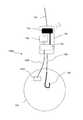
次に、図12を参照して、本発明のさらに他の実施形態に係る餌検出装置について説明する。図12は、本発明のさらに他の実施形態に係る餌検出装置900を概略的に示す図である。餌検出装置900は、図10に示した餌検出装置700を変形したものであり、位置検出センサによってプローブ9022の位置を検出することにより釣り餌が釣り針に保持されているか否かを検出するように構成される。  Next, a bait detection apparatus according to still another embodiment of the present invention will be described with reference to FIG. FIG. 12 is a diagram schematically illustrating abait detection device 900 according to still another embodiment of the present invention. Thebait detection device 900 is a modification of thebait detection device 700 shown in FIG. 10, and detects whether the fishing bait is held by the fishhook by detecting the position of theprobe 9022 by the position detection sensor. Configured.

図12に示した餌検出装置900は、位置検出センサ9021と、プローブ9022と、バネ9024とを備える。プローブ9022は、例えば合成樹脂から成る棒状の部材であり、筐体701に、軸9025の回りで枢動可能に軸支される。プローブ9022は、バネ9024により常時図12の時計回り方向に付勢されている。プローブ9022の先端は、釣り針708に保持された釣り餌705に取り付けられるので、釣り餌705が釣り針708に保持されている場合には、プローブ9022の先端はバネ9024の付勢力に抗して釣り針708の近傍に留まることができる。このプローブ9022の先端が釣り針708の近くにある場合の当該プローブ9022の位置を「第1の位置」ということがある。つまり、プローブ9022は、釣り餌705が釣り針708に保持されている場合には、第1の位置に保持される。一方、釣り針708から釣り餌705が脱落した場合には、バネ9024の付勢力によってプローブ9022の先端が時計回り方向に回転される。このプローブ9022の位置を第2の位置ということがある。つまり、プローブ9022は、釣り餌705が釣り針708から脱落した場合、第2の位置に保持される。  Thebait detection device 900 shown in FIG. 12 includes aposition detection sensor 9021, aprobe 9022, and aspring 9024. Theprobe 9022 is a rod-shaped member made of, for example, a synthetic resin, and is pivotally supported by thehousing 701 so as to be pivotable around ashaft 9025. Theprobe 9022 is constantly urged clockwise by thespring 9024 in FIG. Since the tip of theprobe 9022 is attached to thefishing bait 705 held by thefishing hook 708, when thefishing bait 705 is held by thefishing hook 708, the tip of theprobe 9022 resists the biasing force of thespring 9024. It can stay in the vicinity of 708. The position of theprobe 9022 when the tip of theprobe 9022 is near thefishhook 708 may be referred to as a “first position”. That is, theprobe 9022 is held at the first position when thefishing bait 705 is held by thefishing hook 708. On the other hand, when thefishing bait 705 is dropped from thefishing hook 708, the tip of theprobe 9022 is rotated clockwise by the biasing force of thespring 9024. The position of theprobe 9022 may be referred to as a second position. That is, theprobe 9022 is held at the second position when thefishing bait 705 is dropped from thefishing hook 708.

位置検出センサ9021は、プローブ9022が第1の位置と第2の位置のいずれの位置にあるかを検出することができるセンサである。例えば、位置検出センサ9021として、プローブ9022の回転量を検出し、検出した回転量に対応する電気信号を信号処理部703に出力する回転センサを用いることができる。位置検出センサ9021として、公知の任意の回転センサを用いることができる。例えば、位置検出センサ9021は、ホール素子を用いてプローブ9022の回転量を検出する磁気検出型センサ、プローブ9022との間の電気抵抗の変化を検出する電気抵抗型センサ、プローブ2022との間の静電容量の変化を検出する静電容量型センサ、光学式センサ、高周波発振型の近接センサ、又はこれら以外の各種の公知の位置検出センサであってもよい。  Theposition detection sensor 9021 is a sensor that can detect whether theprobe 9022 is in the first position or the second position. For example, as theposition detection sensor 9021, a rotation sensor that detects the rotation amount of theprobe 9022 and outputs an electrical signal corresponding to the detected rotation amount to thesignal processing unit 703 can be used. As theposition detection sensor 9021, any known rotation sensor can be used. For example, theposition detection sensor 9021 includes a magnetic detection sensor that detects the amount of rotation of theprobe 9022 using a Hall element, an electrical resistance sensor that detects a change in electrical resistance with theprobe 9022, and aprobe 2022. It may be a capacitance type sensor that detects a change in capacitance, an optical sensor, a high-frequency oscillation type proximity sensor, or various other known position detection sensors.

信号処理部703は、位置検出センサ9021から出力される電気信号に基づいて、プローブ9022が第1の位置と第2の位置のいずれにあるかを判定し、その判定結果に基
づいて、釣り針708に釣り餌705が保持されているか否かを示す判定信号を生成することができる。信号処理部703において生成された判定信号は、送信部704から情報出力装置120に送信される。情報出力装置120は、受信した判定信号に基づいて、釣り針に釣り餌が保持されているか否かを示す釣り餌検出情報を釣り人に通知することができる。
Thesignal processing unit 703 determines whether theprobe 9022 is in the first position or the second position based on the electrical signal output from theposition detection sensor 9021, and based on the determination result, thefishing hook 708. A determination signal indicating whether or not thefishing bait 705 is held can be generated. The determination signal generated in thesignal processing unit 703 is transmitted from thetransmission unit 704 to theinformation output device 120. Based on the received determination signal, theinformation output device 120 can notify the angler of fishing bait detection information indicating whether or not the fishing bait is held on the fishing hook.

次に、図13を参照して、本発明のさらに他の実施形態に係る餌検出装置について説明する。図13は、本発明のさらに他の実施形態に係る餌検出装置1000を概略的に示す図である。餌検出装置1000は、図10に示した餌検出装置700を変形したものであり、濃度センサによって釣り餌が釣り針に保持されているか否かを検出するように構成される。  Next, a bait detection device according to still another embodiment of the present invention will be described with reference to FIG. FIG. 13 is a diagram schematically illustrating abait detection device 1000 according to still another embodiment of the present invention. Thebait detection device 1000 is a modification of thebait detection device 700 shown in FIG. 10, and is configured to detect whether or not the fishing bait is held on the fishing hook by a concentration sensor.

図13に示した餌検出装置1000は、信号線1003を介して信号処理部703に接続された濃度センサ1002を備える。濃度センサ1002は、釣り餌705から露出しないように、釣り餌705によって周囲を取り囲まれている。濃度センサ1000として、濃度センサ402と同じものを用いることができる。濃度センサ1002は、例えば、塩分の濃度を測定する塩分濃度計である。餌検出装置1000を淡水で使用し、撒餌705が塩分を含むものである場合などのように、餌検出装置1000の使用環境と撒餌705とに塩分の濃度差がある場合は、濃度センサ1002による塩分濃度の測定結果に基づいて、釣り針708が釣り餌705を保持しているか否かを検出することができる。つまり、釣り餌705が釣り針708に保持されており濃度センサ1002を取り囲んでいる場合には高い塩分濃度が検出され、一方、釣り餌705が釣り針708から脱落した場合には、低い塩分濃度が検出される。濃度センサ1002は、検出した濃度に対応する電気信号を信号処理部703に出力することができる。  Abait detection device 1000 shown in FIG. 13 includes aconcentration sensor 1002 connected to asignal processing unit 703 via asignal line 1003. Theconcentration sensor 1002 is surrounded by thefishing bait 705 so as not to be exposed from thefishing bait 705. As thedensity sensor 1000, the same sensor as thedensity sensor 402 can be used. Theconcentration sensor 1002 is, for example, a salt concentration meter that measures the concentration of salt. When thebait detection device 1000 is used in fresh water and thebait 705 contains salt, when there is a difference in salinity between the environment in which thebait detection device 1000 is used and thebait 705, the salinity concentration by theconcentration sensor 1002 is used. Whether or not thefishing hook 708 holds thefishing bait 705 can be detected based on the measurement result. That is, when thefishing bait 705 is held by thefishhook 708 and surrounds theconcentration sensor 1002, a high salinity concentration is detected, whereas when thefishing bait 705 falls off thefishhook 708, a low salinity concentration is detected. Is done. Thedensity sensor 1002 can output an electrical signal corresponding to the detected density to thesignal processing unit 703.

信号処理部703は、濃度センサ1002から出力される電気信号に基づいて、釣り餌705が釣り針708に保持されているか否かを判定し、その判定結果に基づいて、釣り針708に釣り餌705が保持されているか否かを示す判定信号を生成することができる。信号処理部703において生成された判定信号は、送信部704から情報出力装置120に送信される。情報出力装置120は、受信した判定信号に基づいて、釣り針に釣り餌が保持されているか否かを示す釣り餌検出情報を釣り人に通知することができる。  Thesignal processing unit 703 determines whether thefishing bait 705 is held by thefishhook 708 based on the electrical signal output from theconcentration sensor 1002, and thefishing bait 705 is attached to thefishing hook 708 based on the determination result. A determination signal indicating whether or not it is held can be generated. The determination signal generated in thesignal processing unit 703 is transmitted from thetransmission unit 704 to theinformation output device 120. Based on the received determination signal, theinformation output device 120 can notify the angler of fishing bait detection information indicating whether or not the fishing bait is held on the fishing hook.

次に、図14を参照して、本発明のさらに他の実施形態に係る餌検出装置について説明する。図14は、本発明のさらに他の実施形態に係る餌検出装置1100を概略的に示す図である。餌検出装置1100は、図10に示した餌検出装置700を変形したものであり、超音波の反射波が戻ってくるまでの時間に基づいて釣り餌が釣り針に保持されているか否かを検出するように構成される。  Next, a bait detection device according to still another embodiment of the present invention will be described with reference to FIG. FIG. 14 is a diagram schematically illustrating abait detection device 1100 according to still another embodiment of the present invention. Thebait detection device 1100 is a modification of thebait detection device 700 shown in FIG. 10, and detects whether or not the fishing bait is held by the fishing hook based on the time until the reflected ultrasonic wave returns. Configured to do.

図14に示した餌検出装置1100は、検出用の超音波を発する水中マイク10021と、当該超音波の反射波を受波するハイドロフォン10022とを備える。水中マイク4021は、例えば、釣り針708に向かって超音波を発波できるように、その配置及び向きが調整される。ハイドロフォン10022は、反射波を受けると電気信号を信号処理部703に出力することができる。  Abait detection apparatus 1100 shown in FIG. 14 includes anunderwater microphone 10021 that emits ultrasonic waves for detection, and ahydrophone 10022 that receives reflected waves of the ultrasonic waves. The arrangement and orientation of theunderwater microphone 4021 are adjusted so that, for example, ultrasonic waves can be emitted toward thefishing hook 708. When thehydrophone 10022 receives the reflected wave, thehydrophone 10022 can output an electrical signal to thesignal processing unit 703.

信号処理部703は、ハイドロフォン10022から出力された電気信号に基づいて、水中マイク10021からの検出用超音波の発波からその反射波を受けるまでの時間を計測することができる。釣り針708に釣り餌705が保持されている場合には、検出用超音波の発波からその反射波を受波するまでの時間が短く、一方、釣り針708に釣り餌705が脱落した場合には、釣り針708の付近に超音波を反射する物体が存在しないので、検出用超音波の発波からその反射波を受波するまでの時間が長くなる。したがって、信
号処理部703は、検出用超音波の発波からその反射波を受波するまでの時間を所定の閾値と比較することにより、釣り餌705が釣り針708に保持されているか否かを判定することができる。その判定結果に基づいて、釣り針708に釣り餌705が保持されているか否かを示す判定信号を生成することができる。信号処理部703において生成された判定信号は、送信部704から情報出力装置120に送信される。情報出力装置120は、受信した判定信号に基づいて、釣り針に釣り餌が保持されているか否かを示す釣り餌検出情報を釣り人に通知することができる。
Based on the electrical signal output from thehydrophone 10022, thesignal processing unit 703 can measure the time from when the detection ultrasonic wave is generated from theunderwater microphone 10021 until the reflected wave is received. When thefishing bait 705 is held on thefishhook 708, the time from receiving the detection ultrasonic wave to receiving the reflected wave is short. On the other hand, if thefishing bait 705 falls off thefishhook 708, Since there is no object that reflects the ultrasonic wave in the vicinity of thefishing hook 708, the time from when the ultrasonic wave for detection is generated until the reflected wave is received becomes longer. Therefore, thesignal processing unit 703 determines whether or not thefishing bait 705 is held by thefishhook 708 by comparing the time from the generation of the detection ultrasonic wave to the reception of the reflected wave with a predetermined threshold value. Can be determined. Based on the determination result, a determination signal indicating whether or not thefishing bait 705 is held on thefishing hook 708 can be generated. The determination signal generated in thesignal processing unit 703 is transmitted from thetransmission unit 704 to theinformation output device 120. Based on the received determination signal, theinformation output device 120 can notify the angler of fishing bait detection information indicating whether or not the fishing bait is held on the fishing hook.

本発明の実施形態は、上述した実施形態に限定されるものではなく、その要旨を逸脱しない範囲内で様々な変更が可能である。例えば、上述した実施形態における各部材の、材質、形状、寸法、形態、数、又は配置等は適宜変更され得る。例えば、撒餌容器内の撒餌の残量を検出する具体的な方法は、本明細書に明示したものに限られない。撒餌の残量の具体的な検出方法は、使用する撒餌の種類に応じて最適な検出方法を用いることができる。  The embodiment of the present invention is not limited to the above-described embodiment, and various modifications can be made without departing from the scope of the invention. For example, the material, shape, dimensions, form, number, arrangement, etc., of each member in the above-described embodiment can be changed as appropriate. For example, a specific method for detecting the remaining amount of bait in the bait container is not limited to that specified in this specification. As a specific method for detecting the remaining amount of bait, an optimum detection method can be used according to the type of bait used.

100、200、300、400、500、600 撒餌容器
101 本体
103、703 信号処理部
104、704 送信部
105 撒餌
120 情報出力装置
121 受信部
122 復調部
123 出力部
1021、7022 受光ユニット
1022、7021 投光ユニット
2021、9021 位置検出センサ
2022、9022 プローブ
2023 永久磁石
2324、9024 バネ
3021 圧力検出センサ
3022 バネ
3023 ピストン
402、1002 濃度センサ
4021、10021 水中マイク
4022、10022 ハイドロフォン
700、800、900、1000、1100 餌検出装置
701 筐体
705 釣り餌
902 光センサ
100, 200, 300, 400, 500, 600Bait container 101Main body 103, 703Signal processing unit 104, 704Transmitter 105Bait 120Information output device 121Receiver 122Demodulator 123Output unit 1021, 7022Light receiving unit 1022, 7021Throw Optical unit 2021, 9021Position detection sensor 2022, 9022Probe 2023Permanent magnet 2324, 9024Spring 3021Pressure detection sensor 3022Spring 3023Piston 402, 1002Concentration sensor 4021, 10021Underwater microphone 4022, 10028Hydrophone 700, 800, 900, 1000, 1100Bait Detection Device 701Housing 705 Fishing Bait 902 Optical Sensor

Claims (7)

Translated fromJapanese
その内部に撒餌を収容するとともに前記撒餌を外部に放出可能に構成され、釣糸を介して釣竿に取り付けられる本体と、
当該本体内に収容されている撒餌の残量に応じた光量を検出する光電変換部を備える残量検出部と、
該残量検出部に給電する電源と、
該残量検出部及び該電源への漏水を防止する防水手段と、
を備える撒餌容器。
A main bodythat is configured to accommodatethe bait inside and to be able torelease the bait to the outside, andis attached to the fishing rod via a fishing line ,
A remaining amount detection unit comprising a photoelectric conversion unit that detects the amount of light according to the remaining amount of bait contained in the main body;
A power source for supplying power to the remaining amount detection unit;
Waterproof means for preventing water leakage to the remaining amount detection unit and the power source;
A bait container comprising:
前記撒餌の残量を示す残量信号を水中から送信する送信部をさらに備えることを特徴とする請求項1に記載の撒餌容器。  The bait container according to claim 1, further comprising a transmission unit that transmits a remaining amount signal indicating the remaining amount of the bait from underwater. 前記本体は、光を透過しない遮光部材を備え、
前記残量検出部は、光を発する投光部と、該光を受光する受光部と、を備えることを特徴とする請求項1又は2に記載の撒餌容器。
The main body includes a light shielding member that does not transmit light,
The bait container according to claim 1, wherein the remaining amount detection unit includes a light projecting unit that emits light and a light receiving unit that receives the light.
前記投光部と、前記受光部とは並んで配置され、
前記受光部は、撒餌からの反射光を受光することを特徴とする請求項3に記載の撒餌容器。
The light projecting unit and the light receiving unit are arranged side by side,
The bait container according to claim 3, wherein the light receiving unit receives reflected light from the bait.
前記投光部と、前記受光部とは対向して配置され、
前記投光部と、前記受光部との間に、前記撒餌が配置されることを特徴とする請求項3に記載の撒餌容器。
The light projecting unit and the light receiving unit are disposed to face each other.
The bait container according to claim 3, wherein the bait is disposed between the light projecting unit and the light receiving unit.
前記残量検出部は、環境光を受光可能な受光部を備えることを特徴とする請求項1に記載の撒餌容器。  The bait container according to claim 1, wherein the remaining amount detection unit includes a light receiving unit capable of receiving ambient light. 前記送信部は、前記残量信号によって変調された音波を送信することを特徴とする請求項2に記載の撒餌容器。
The bait container according to claim 2, wherein the transmission unit transmits a sound wave modulated by the remaining amount signal.
JP2018071551A2018-04-032018-04-03 A bait detection device capable of detecting whether the amount of the bait is detected or whether the fishing hook holds the baitActiveJP6582088B2 (en)

Priority Applications (1)

Application NumberPriority DateFiling DateTitle
JP2018071551AJP6582088B2 (en)2018-04-032018-04-03 A bait detection device capable of detecting whether the amount of the bait is detected or whether the fishing hook holds the bait

Applications Claiming Priority (1)

Application NumberPriority DateFiling DateTitle
JP2018071551AJP6582088B2 (en)2018-04-032018-04-03 A bait detection device capable of detecting whether the amount of the bait is detected or whether the fishing hook holds the bait

Related Parent Applications (1)

Application NumberTitlePriority DateFiling Date
JP2014200647ADivisionJP6514870B2 (en)2014-09-302014-09-30 A bait container capable of detecting the amount of bait bait and a bait detector capable of detecting whether or not a fishing hook holds bait

Publications (2)

Publication NumberPublication Date
JP2018121647A JP2018121647A (en)2018-08-09
JP6582088B2true JP6582088B2 (en)2019-09-25

Family

ID=63108912

Family Applications (1)

Application NumberTitlePriority DateFiling Date
JP2018071551AActiveJP6582088B2 (en)2018-04-032018-04-03 A bait detection device capable of detecting whether the amount of the bait is detected or whether the fishing hook holds the bait

Country Status (1)

CountryLink
JP (1)JP6582088B2 (en)

Families Citing this family (2)

* Cited by examiner, † Cited by third party
Publication numberPriority datePublication dateAssigneeTitle
KR102533907B1 (en)*2020-08-252023-05-18김가은A underwater fish luring light control system
US11678651B1 (en)*2022-11-082023-06-20Amos ChessOn board chumming system for a boat and boat having same

Family Cites Families (3)

* Cited by examiner, † Cited by third party
Publication numberPriority datePublication dateAssigneeTitle
JPH0323094Y2 (en)*1987-04-101991-05-20
CA2860007C (en)*2010-12-232020-04-14Xpertsea Solutions Inc.Photo-coupled data acquisition system and method
KR101024386B1 (en)*2011-01-202011-03-23엔엔티시스템즈(주) Automatic feed system for cage farms

Also Published As

Publication numberPublication date
JP2018121647A (en)2018-08-09

Similar Documents

PublicationPublication DateTitle
US4805337A (en)Fish sonar body
US7272075B2 (en)Personal sonar system
Li et al.Recent advances in acoustic technology for aquaculture: A review
JP6582088B2 (en) A bait detection device capable of detecting whether the amount of the bait is detected or whether the fishing hook holds the bait
US20070147173A1 (en)Simplicity sonic depth finder for fishing
JPH0224469Y2 (en)
JP3640852B2 (en) Unmanned boat for remotely controlled fishing and its remotely controlled device
JP6514870B2 (en) A bait container capable of detecting the amount of bait bait and a bait detector capable of detecting whether or not a fishing hook holds bait
US20160278360A1 (en)Systems and methods for monitoring and communicating fishing data
US20130333270A1 (en)Multiple Mode Artificial Fishing Lure
US12171205B2 (en)System and method for attracting crustaceans and other aquatic life
JP6545941B2 (en) Fish signal detection device and information output device
US9488728B2 (en)Digital depth readout adapter for flasher type fish finder
US9210917B1 (en)Bait-fish trap
KR20110123911A (en) Fish location tracking system and method for fishery resource management
KR100731784B1 (en)Simplicity sonic depth finder for fishing
JP7126997B2 (en) A bait storage device capable of outputting the distribution of bait
JP2006230364A (en)Apparatus for monitoring fish school
JP2017194885A (en)Underwater Sensor
JP2002286841A (en)Fish detector for fishing tackle
JP6903027B2 (en) Feeding storage device that can output the remaining amount of feeding
KR20220020117A (en)Biting signal sensor for fishing
KR100593260B1 (en) Moving luer
JP7165635B2 (en) Bait storage device capable of detecting external bait position and bait position detection system
CA2167180A1 (en)Remote activity sensing system

Legal Events

DateCodeTitleDescription
A521Request for written amendment filed

Free format text:JAPANESE INTERMEDIATE CODE: A523

Effective date:20180404

A621Written request for application examination

Free format text:JAPANESE INTERMEDIATE CODE: A621

Effective date:20180404

A977Report on retrieval

Free format text:JAPANESE INTERMEDIATE CODE: A971007

Effective date:20190220

A131Notification of reasons for refusal

Free format text:JAPANESE INTERMEDIATE CODE: A131

Effective date:20190226

A601Written request for extension of time

Free format text:JAPANESE INTERMEDIATE CODE: A601

Effective date:20190424

A521Request for written amendment filed

Free format text:JAPANESE INTERMEDIATE CODE: A523

Effective date:20190612

TRDDDecision of grant or rejection written
A01Written decision to grant a patent or to grant a registration (utility model)

Free format text:JAPANESE INTERMEDIATE CODE: A01

Effective date:20190827

A61First payment of annual fees (during grant procedure)

Free format text:JAPANESE INTERMEDIATE CODE: A61

Effective date:20190902

R150Certificate of patent or registration of utility model

Ref document number:6582088

Country of ref document:JP

Free format text:JAPANESE INTERMEDIATE CODE: R150

RD02Notification of acceptance of power of attorney

Free format text:JAPANESE INTERMEDIATE CODE: R3D02

R250Receipt of annual fees

Free format text:JAPANESE INTERMEDIATE CODE: R250

R250Receipt of annual fees

Free format text:JAPANESE INTERMEDIATE CODE: R250

R250Receipt of annual fees

Free format text:JAPANESE INTERMEDIATE CODE: R250

R250Receipt of annual fees

Free format text:JAPANESE INTERMEDIATE CODE: R250


[8]ページ先頭

©2009-2025 Movatter.jp