JP6581707B2 - Nucleic acid analyzer and nucleic acid analysis method - Google Patents
Nucleic acid analyzer and nucleic acid analysis methodDownload PDFInfo
- Publication number
- JP6581707B2 JP6581707B2JP2018181228AJP2018181228AJP6581707B2JP 6581707 B2JP6581707 B2JP 6581707B2JP 2018181228 AJP2018181228 AJP 2018181228AJP 2018181228 AJP2018181228 AJP 2018181228AJP 6581707 B2JP6581707 B2JP 6581707B2
- Authority
- JP
- Japan
- Prior art keywords
- nucleic acid
- fluorescence
- dichroic mirror
- acid analyzer
- fluorescent
- Prior art date
- Legal status (The legal status is an assumption and is not a legal conclusion. Google has not performed a legal analysis and makes no representation as to the accuracy of the status listed.)
- Active
Links
Images


Landscapes
- Investigating, Analyzing Materials By Fluorescence Or Luminescence (AREA)
- Optical Filters (AREA)
- Apparatus Associated With Microorganisms And Enzymes (AREA)
- Measuring Or Testing Involving Enzymes Or Micro-Organisms (AREA)
Description
Translated fromJapanese本発明は、複数の光学フィルタを用いて蛍光観察による核酸分析を行う装置および核酸分析方法に関する。 The present invention relates to an apparatus for performing nucleic acid analysis by fluorescence observation using a plurality of optical filters and a nucleic acid analysis method.
次世代シーケンサの計測は、多数の微小反応場が固定されたフローセルを用いて行われる。フローセル上に固定された微小反応場上にて化学反応を行い、蛍光観察を行うことにより、目的とするDNAの塩基配列の解析が可能になる。フローセルは多数の微小反応場を固定したスライドガラス程度の大きさの消耗品であり、反応試薬の置換を行えるように注入口や排出口をもつ流路が構造をとっている。フローセルに必要な酵素や蛍光標識されたヌクレオチドなどの試薬を流しいれることにより、塩基伸長反応が行われる。これらの反応は必要に応じて適切な温度に制御する必要がある。フローセルは温調を行うことが可能なヒートブロックに密着して配置されているため、フローセルのもう片側に対物レンズを配置する。対物レンズを介してフローセルに固定された反応場に励起光を照射し、蛍光を検出する。この蛍光をCCDカメラやCMOSカメラなどの2次元センサで捉えることにより、蛍光画像として塩基情報を入手することができる。 The next-generation sequencer is measured using a flow cell in which a large number of minute reaction fields are fixed. By performing a chemical reaction on a micro reaction field fixed on the flow cell and performing fluorescence observation, it becomes possible to analyze the base sequence of the target DNA. A flow cell is a consumable product about the size of a slide glass on which a large number of micro reaction fields are fixed, and a flow path having an inlet and an outlet is constructed so that the reaction reagent can be replaced. A base extension reaction is carried out by pouring a reagent such as an enzyme necessary for the flow cell or a fluorescently labeled nucleotide. These reactions need to be controlled at an appropriate temperature as required. Since the flow cell is disposed in close contact with a heat block capable of controlling the temperature, an objective lens is disposed on the other side of the flow cell. The reaction field fixed to the flow cell is irradiated with excitation light through the objective lens, and fluorescence is detected. By capturing this fluorescence with a two-dimensional sensor such as a CCD camera or a CMOS camera, base information can be obtained as a fluorescence image.
フローセルの反応場の領域は一般に、対物レンズにて測定できる視野よりも大きい。対物レンズは固定されており、固定された対物レンズの光軸に対してフローセルの位置を駆動させることでフローセルの測定領域全域で蛍光画像の撮影を行う。例えばフローセルの反応領域が35mm×4mmである場合は、フローセル140mm2の領域を蛍光画像として取得することが可能である。対物レンズの視野はおよそ1 mm2であるため、フローセルをXYステージに固定し、一定距離駆動させることにより、隣接したパネルを逐次蛍光観察していく。The reaction field area of the flow cell is generally larger than the field of view that can be measured with an objective lens. The objective lens is fixed, and a fluorescent image is taken over the entire measurement region of the flow cell by driving the position of the flow cell with respect to the optical axis of the fixed objective lens. For example, when the reaction area of the flow cell is 35 mm × 4 mm, the area of the flow cell 140 mm2 can be acquired as a fluorescence image. Since the field of view of the objective lens is approximately 1 mm2 , the flow cell is fixed to the XY stage and driven by a certain distance, so that adjacent panels are sequentially observed with fluorescence.
次世代シーケンサにおいて重要視される指標のひとつとしてスループットがある。スループットとは単位時間当たりに解析できる総塩基数であり、これを増加させるために技術開発が進んでいる。スループットを向上させるためには大きく二つの方針がある。ひとつは、フローセルに固定する反応場の大きさを縮小し、密に配置することで一度の撮影あたりに取得可能な塩基情報を増加させることである。従来では、ランダム配置によって反応場の固定を行っている。今日では、反応場の小型化とパターン配置することによって、より密に充填することが可能になっている。もう一方として、蛍光観察を行う時間の短縮がある。次世代シーケンサでは、各塩基に対応した4種類の蛍光色素が用いられている。それぞれの色素に対応した励起光の照射、蛍光の分離が必要である。従来では、各色素に対応した4種類のフィルタセットを用いて検出を行うことが一般的である。この方式では、4種類の励起光と励起光と蛍光を分離するためのダイクロイックミラー、蛍光用のフィルタと少なくとも12種類の光学素子を用いることと、各フィルタセットを切り替えるための機構が必要である。蛍光観察の時間に関して、例えば、1色の撮影時間を200ms、測定するパネル数を140パネルとすると、およそ蛍光撮影だけで2分の時間を要する。スループットの向上には、これらの読み取り時間をより短縮することが必要である。特許文献1では、複数枚のダイクロイックミラーにて蛍光を分離し、2台の2次元センサによって撮影することによって、一度の撮影にて2色の色素を同時に読み取ることができる。この方式を用いることでフィルタセットの切替を行う機構を単純化するとともに、蛍光撮影に要する時間をおよそ半分まで短縮することができる。しかし、複数枚のダイクロイックミラーの分光特性の変化が大きな問題になる。ダイクロイックミラーに対する入射光の角度が変化することで分光特性が変化するため、測定視野内の一部の領域について目的とする分光特性を得ることができなくなる可能性がある。 One of the important indexes in next-generation sequencers is throughput. Throughput is the total number of bases that can be analyzed per unit time, and technological development is progressing to increase this. There are two main strategies for improving throughput. One is to reduce the size of the reaction field fixed to the flow cell and to increase the base information that can be acquired per image taking by densely arranging them. Conventionally, the reaction field is fixed by random arrangement. Today, it is possible to pack more densely by miniaturizing the reaction field and arranging the pattern. On the other hand, there is a reduction in time for performing fluorescence observation. The next-generation sequencer uses four types of fluorescent dyes corresponding to each base. It is necessary to irradiate excitation light corresponding to each dye and to separate fluorescence. Conventionally, detection is generally performed using four types of filter sets corresponding to each dye. This method requires four types of excitation light, a dichroic mirror for separating excitation light and fluorescence, a filter for fluorescence and at least 12 types of optical elements, and a mechanism for switching each filter set. . With respect to the fluorescence observation time, for example, if the imaging time for one color is 200 ms and the number of panels to be measured is 140 panels, it takes about 2 minutes only for fluorescent imaging. In order to improve the throughput, it is necessary to further shorten these reading times. In
蛍光の分離および色素の特定の精度はダイクロイックミラーの光学特性に依存する。ダイクロイックミラーへの入射角度が変化することに伴い、光学特性には変化が生じる。そのため、各ダイクロイックミラーの配置によって測定視野内で分析不可となる領域が生じる。本発明では、視野全域にて複数の蛍光色素を同時に観察し、精度よく色素の特定を行い、得られた蛍光色から核酸配列を決定することができる核酸分析装置の構成及び分析方法を提供する。 The separation of the fluorescence and the specific accuracy of the dye depends on the optical properties of the dichroic mirror. As the incident angle to the dichroic mirror changes, the optical characteristics change. For this reason, an area that cannot be analyzed in the measurement visual field is generated by the arrangement of each dichroic mirror. The present invention provides a configuration and analysis method of a nucleic acid analyzer capable of simultaneously observing a plurality of fluorescent dyes in the entire visual field, accurately identifying the dyes, and determining a nucleic acid sequence from the obtained fluorescent colors. .
上記課題を解決するために、試薬や試料を送液する送液機構と、送液される流路を有する基板と、前記基板を設置するステージと、塩基伸長反応を行う温調機構と、蛍光を検出し、蛍光画像を観察する検出部を備える核酸分析装置において、
前記検出部は、光源と、所定の波長域を通過させる複数の光学フィルタと、対物レンズと、励起光を反射させ、蛍光を通過させる第1のダイクロイックミラーと、蛍光色素から発した蛍光を色素毎に異なる割合で分離する第2のダイクロイックミラーと、分離後にそれぞれの蛍光を検出する少なくとも2つの2次元センサとを備え、
前記基板は、前記各2次元センサにて画像上に検出されるマークを有し、
前記各2次元センサにて取得した画像の画像位置合わせを、画像上に検出される基板のマークを用いて行い、前記マークを基準として視野内の領域を複数に分割し、分割した領域毎に前記第1および前記第2のダイクロイックミラーの分光特性の分離比率変化の計算値を用いて蛍光色素解析を行うことを特徴とする核酸分析装置および、分析方法を提供する。In order to solve the above problems, a liquid feeding mechanism for feeding a reagent or a sample, a substrate having a flow path for feeding a liquid, a stage on which the substrate is installed, a temperature control mechanism for performing a base extension reaction, a fluorescence In the nucleic acid analyzer comprising a detection unit for detecting the fluorescence imageand observing
The detection unit includes a light source, a plurality of optical filters that pass a predetermined wavelength range, an objective lens, a first dichroic mirror that reflects excitation light and passes fluorescence, and fluorescence emitted from the fluorescent dye. A second dichroic mirror that separates at different rates for each, and at least two two-dimensional sensors that detect the respective fluorescence after separation,
The substrate has a mark detected on an image by each of the two-dimensional sensors,
Image alignment of images acquired by each of the two-dimensional sensors is performed using a mark on the substrate detected on the image, and an area in the field of view is divided into a plurality of areas based on the mark, and for each divided area There are provided a nucleic acid analyzer and an analysis method characterized in that fluorescent dye analysis is performed using calculated values of separation ratio changes in spectral characteristics of the first and second dichroic mirrors.
本発明によれば、ダイクロイックミラーによって分離した蛍光を2台のカメラで撮影し、各カメラで掲出される各点の輝度の比率を元にして色素の特定を行う。色素を特定する際に、測定視野を複数に分割して分割視野毎に解析を行うことで、全視野で精度よく色素の特定を行うことが可能になり、特定された蛍光色の配列が決定され、最終的に塩基配列が決定可能となる。 According to the present invention, the fluorescence separated by the dichroic mirror is photographed by two cameras, and the pigment is specified based on the luminance ratio of each point posted by each camera. When specifying the dye, the measurement field is divided into multiple areas and analysis is performed for each divided field, so that the dye can be accurately identified in the entire field of view, and the arrangement of the specified fluorescent color is determined. Finally, the base sequence can be determined.
複数の蛍光色素を同時に蛍光検出が可能になる。また、測定視野の全域で精度よく色素の特定を行うが可能になるため、装置スループットが向上する。前述した以外の課題、構成及び効果は、以下の実施形態の説明により明らかにされる。 A plurality of fluorescent dyes can be detected simultaneously. In addition, since it becomes possible to accurately identify the dye throughout the entire measurement visual field, the apparatus throughput is improved. Problems, configurations, and effects other than those described above will become apparent from the following description of embodiments.
以下、図面に基づいて、本発明の実施の形態を説明する。なお、本発明の実施の態様は、後述する実施例に限定されるものではなく、その技術思想の範囲において、種々の変形が可能である。 Hereinafter, embodiments of the present invention will be described with reference to the drawings. The embodiment of the present invention is not limited to the examples described later, and various modifications are possible within the scope of the technical idea.
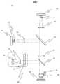
図1を用いて核酸分析装置100の概要を説明する。核酸分析装置は複数の試薬が保持される試薬容器101を収容する試薬冷却保管庫102と、試薬容器101に保持される試薬を送液する反応試薬送液機構103とDNA断片が結合した流路を有するフローセル104と、フローセル内でDNA断片と試薬の反応を促進させる温調機構105と、DNA断片に取り込まれた蛍光を検出する検出部106とから構成される。事前に調整されたフローセル104は送液機構103によって各反応液が送液される。必要に応じて温調機構105によって加熱及び冷却することにより、フローセル内で伸長反応をし、蛍光を発する。検出部106において、蛍光検出を行い、塩基配列の決定を行う。反応後余分なサンプルや試薬は、廃液タンク109に収容される。 The outline of the
本発明の核酸分析装置を用いて様々な核酸分析を実施することができる。例えば、DNA配列決定やハイブリダイゼーションを行うことが可能である。特に本発明に関わる核酸分析装置100を用いてDNA配列決定を行うことが可能である。各反応試薬をフローセル内に送液することにより、フローセルに固定されたDNA断片に蛍光色素を含む塩基を結合させる。反応液には、蛍光標識された4種類の塩基及びポリメラーゼが含まれている。各塩基はそれぞれ FAM, Cy3, Texas Red, Cy5で蛍光標識されている。反応液には、伸長反応が効率的に行なわれるように塩濃度、マグネシウム濃度およびpHが最適化されている。反応溶液中にはポリメラーゼが含まれており、DNA断片に相補的な蛍光ヌクレオチドが1塩基だけ取り込まれる。2塩基目の伸長が発生しないのは、1塩基目の蛍光色素に2塩基目の色素の伸長を阻害する物質が結合しているからである。1塩基が取り込まれた後、浮遊する蛍光ヌクレオチドを洗浄により除去する。 Various nucleic acid analyzes can be performed using the nucleic acid analyzer of the present invention. For example, DNA sequencing and hybridization can be performed. In particular, it is possible to perform DNA sequencing using the
検出部106にて蛍光色素に励起光を照射し、蛍光観察を行う。その後、蛍光部分を切断し、さらに伸長反応を行い、蛍光観察を再度実行する。これらを繰り返すことにより、4色の蛍光色の配列が決定され、最終的に塩基配列が決定される。この方法により、1サイクルで数十〜数百bpの解析を行うことができ、1ランで数十Gbpのデータを解析することが可能である。 The
本発明の核酸分析装置100は、2枚のダイクロイックミラーにより蛍光を分離し、2台の二次元カメラを用いて検出を行う。 The
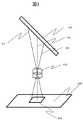
検出部106は、図2に示すように、励起光照射部201と励起蛍光用ダイクロイックミラー202と対物レンズ203と蛍光フィルタ204と色分離用ダイクロイックミラー205とチューブレンズ206および207と2次元イメージセンサ208および209とから構成される。励起光照射部201は白色光源220とコリメートレンズ221と複数枚の光学フィルタを収容したフィルタ切替機構222から構成される。白色光源としては、Xeランプや白色LEDなど高輝度の白色光を出射可能な光源を用いる。また、必要に応じて光源を冷却するための冷却機構を備える。コリメートレンズ221は、光源から出射された光を集光し、平行光へと変換する。光源とコリメートレンズの間には、光源の光を均一にするためにライトガイドを挿入する。ライトガイドとしては液体ライトガイドやライトパイプなどを使用することができる。本実施例では白色光源としてマルチアレイLEDを用い、ライトパイプを用いて出射光を均一化している。フィルタ切替機構222は、複数枚の光学フィルタを収納し、それぞれのフィルタに切り替えることで、白色光から励起光として使用する波長域の光を透過させる。本実施例では、短波長域に単一のバンドを持つ光学フィルタと長波長域に単一のバンドを持つ光学フィルタの二種類を収容し、それぞれのフィルタに切り替える機構を備える。フィルタの切り替えの機構としては、例えばモータ、ソレノイドなどを用いることが可能である。 As shown in FIG. 2, the
励起光照射部200では、白色光源から出射された光がコリメートレンズにより並行光に変換され、その後フィルタ切替機構222に備え付けられている光学フィルタを透過することで、励起光として使用する波長域の平行光を出射する。励起光照射部から出射された光は、励起蛍光用ダイクロイックミラー202へと入射する。励起蛍光用ダイクロイックミラーは、光軸に対して45度の角度で設置される。2つの波長域でバンドを持ち、入射した励起光を反射、蛍光を透過させる。励起蛍光用ダイクロイックミラーにより反射した励起光は対物レンズ203に入射する。対物レンズ203はZ軸方向に駆動するZステージ210に取り付けられている。Zステージの駆動によりフローセル104の測定面にピント合わせを実施する。フローセル104内の蛍光色素より発せられた蛍光は再度対物レンズを通過し、励起蛍光用ダイクロイックミラー202を透過する。透過した蛍光は、蛍光フィルタ204によって特定のバンドのみ透過する。その後、蛍光は色分離用ダイクロイックミラー205へと入射する。色分離用ダイクロイックミラー205は4つの色素から蛍光波長に対して、緩やかな光学特性をもつ。そのため、蛍光色素から発した蛍光は、色素ごとに異なる割合で色分離用ダイクロイックミラー205を透過または反射する。透過光および反射光は、それぞれチューブレンズ206および207により集光され、2次元カメラ208および209に結像する。2次元カメラ208および209の直前にフィールドフラットナ211および212を配置することにより、光学性能を向上させることが可能である。色分離用ダイクロイックミラー205の光学特性により、測定視野の輝点から発せられた蛍光は、異なる輝度で検出される。各2次元カメラで撮影された蛍光画像の輝点の蛍光強度比を求めることにより、4色のうちいずれの蛍光色素であるか特定が可能になる。 In the excitation light irradiation unit 200, the light emitted from the white light source is converted into parallel light by the collimator lens, and then transmitted through the optical filter provided in the
本実施例では、図2に示すように励起蛍光用ダイクロイックミラー及び色分離用ダイクロイックミラーの配置は光軸に対して同一の方向をもって配置される。 In this embodiment, as shown in FIG. 2, the arrangement of the excitation fluorescence dichroic mirror and the color separation dichroic mirror is arranged in the same direction with respect to the optical axis.
対物レンズ203を通過した蛍光は、完全な並行光ではなく、対物レンズにて測定可能な視野の位置に依存してある角度もっている。例えば、FN26、倍率20倍の対物レンズの測定可能な視野はΦ1.3mmの領域であるが、図3に示すように、視野中心部の光線301を基準とすると、視野端では最大で4.2度の角度がついた光線302および303となる。ダイクロイックミラーの光学特性は入射角度に依存して特性に変化が生じる。図4に一例を示す。45度で入射した場合の特性401と比較して49度で入射する光303は短波長側透過域が変化した特性402に、41度で入射する光302は長波長側透過域が変化した特性403に変化する。2枚のダイクロイックミラーを互い違いに配置すると、例えば、励起蛍光用ダイクロイックミラーに49度で入射した光線は、色分離用ダイクロイックミラーに対して41度で入射する。各ダイクロイックミラーに生じる特性変化はそれぞれ短波長・長波長を反対の波長方向に変化するため、測定視野の一部についてすべての蛍光が透過または反射してしまう。そのため、色分離用ダイクロイックミラー205にて異なる比率で蛍光を分離することができなくなり、色素の特定ができなくなる。1視野の撮影で解析可能な領域が減少する。 The fluorescence that has passed through the
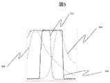
本実施例では、4色の蛍光ヌクレオチドとしてFAM, Cy3, Texas Red, Cy5を用いる。500nm付近にピークを持つ光学フィルタを用いることにより、FAM, Cy3の二つを同時に励起、蛍光観察を行う。また、600nm付近にピークをもつ光学フィルタを用いることにより、Texas Red, Cy5の二つを同時に励起、蛍光観察を実施する。一例としてFAMとCy3の場合の各ダイクロイックミラーの分光特性と蛍光の特性について図5に示す。励起蛍光分離ダイクロイックミラーを透過したFAMの蛍光は、色分離用ダイクロイックミラーによって透過光603と反射光604に分離され、検出される。その後、色分離用ダイクロイックミラーを透過した蛍光は、図6.に示すように各蛍光色素に対して、緩やかな特性を持つダイクロイックミラーにて透過光と反射光に分離される。色分離用各色素における透過と反射の比率は、FAMで50:50,Cy3で30:70,TxRで70:30,Cy5で5:95というようになっている。分離の比率は任意であるが、色素間で同じ比率を取らないようにすることで、より精度よく色素の特定が可能である。 In this example, FAM, Cy3, Texas Red, and Cy5 are used as four-color fluorescent nucleotides. By using an optical filter with a peak near 500 nm, FAM and Cy3 are simultaneously excited and fluorescence observation is performed. In addition, by using an optical filter having a peak near 600 nm, both Texas Red and Cy5 are excited simultaneously and fluorescence observation is performed. As an example, FIG. 5 shows the spectral characteristics and fluorescence characteristics of each dichroic mirror in the case of FAM and Cy3. The FAM fluorescence transmitted through the excitation fluorescence separation dichroic mirror is separated into transmitted light 603 and reflected light 604 by the color separation dichroic mirror and detected. Thereafter, the fluorescence transmitted through the dichroic mirror for color separation is separated into transmitted light and reflected light by a dichroic mirror having gentle characteristics for each fluorescent dye as shown in FIG. The ratio of transmission and reflection in each color separation dye is 50:50 for FAM, 30:70 for Cy3, 70:30 for TxR, and 5:95 for Cy5. The separation ratio is arbitrary, but the dye can be specified with higher accuracy by avoiding the same ratio between the dyes.
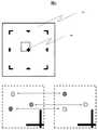
励起光照射部のコリメートレンズの前に視野絞りを入れることが可能である。一度の撮影で計測する視野304は四角形であるため、そのまま励起光を照射すると、図7に示す対物レンズの最大視野701の領域を照射する。視野絞りの挿入することで、測定視野の領域702のみを照射することが可能になる。測定視野以外への照射は測定対象としている蛍光色素の退色を生じさせるため、測定視野以外への照射は極力なくすことが重要である。視野絞りの挿入によって、測定視野外の蛍光色素の退色を抑えることが可能である。しぼり外周部への励起光をしっかりと遮断するために、励起光照射部のコリメートレンズとしては、クリティカル照明または、ケーラ照明を用いる。 It is possible to put a field stop in front of the collimating lens of the excitation light irradiation unit. Since the field of
本装置では、二つのカメラによって検出した蛍光の比率を算出することで色素の特定を行う。検出の方法は次の通りである。まず、2つのカメラによって取得した蛍光画像から同じ輝点の抽出を行う。次に、抽出した各点の輝度情報からそれぞれの比率を算出する。
その後、算出した輝度の比率を元にして蛍光色素の特定を行う。フローセルには、図7に示すように、各測定視野内に位置検出用のマーク801をもっている、図7には十字のマーク等を記載しているがこの形状及び個数は任意の数をとることができる。このマークは、各パネルに必ず測定されるようにパターン化されている。カメラにて検出される画像上で、マークの領域は蛍光がないダークの領域として検出される。パターン認識などを用いてマークの位置の検出が可能である。本実施例では、マーク位置座標を元にして、各カメラにて取得した蛍光画像から同一輝点の抽出を行う。各輝点について、透過側または反射側で検出された光の強度比を算出する。輝点抽出の方法及び各点の輝度の算出の方法は、様々であるが、ガウシアンフィッティングを行うことによって輝点の中心座標、輝度を算出することが可能である。In this apparatus, the pigment is specified by calculating the ratio of the fluorescence detected by the two cameras. The detection method is as follows. First, the same bright spot is extracted from the fluorescence images acquired by the two cameras. Next, each ratio is calculated from the luminance information of each extracted point.
Thereafter, the fluorescent dye is specified based on the calculated luminance ratio. As shown in FIG. 7, the flow cell has a
各色素での分離比率は、フィルタ及びダイクロイックミラーの特性に依存して変化するため、ダイクロイックミラーの設計値から算出した各色素の分離比率と各輝点から得られた比率を比較することにより輝点の色素を特定することができる。 Since the separation ratio for each dye changes depending on the characteristics of the filter and dichroic mirror, the separation ratio of each dye calculated from the design value of the dichroic mirror is compared with the ratio obtained from each bright spot. A point dye can be identified.
ダイクロイックミラーに入射する光の角度によってダイクロイックミラーの分光特性は変化する。図3に示す光線301〜303のように視野の位置に依存して入射角度が異なる。視野全域を同じ比率で分離すると、視野端に位置する輝点の解析精度が悪くなる。そこで、視野をいくつかの領域に分けてそれぞれの領域にて異なる比率で分離することで視野全域を精度よく分離を行うことが可能である。視野の分割には、例えば視野内のマークを基準として16分割し、分割した領域毎にダイクロイックミラーの分光特性の変化を考慮した計算値を用いることにより、精度よく色素の特定を行うことが可能である。 The spectral characteristics of the dichroic mirror vary depending on the angle of light incident on the dichroic mirror. Like the
100 核酸分析装置
101 試薬容器
102 試薬保管庫
103 送液機構
104 フローセル
105 温調機構
106 検出部
107 XYステージ
108 送液用シリンジ
109 廃液部
201 励起光照射部
202 励起蛍光用ダイクロイックミラー
203 対物レンズ
204 蛍光フィルタ
205 色分離用ダイクロイックミラー
206、207 チューブレンズ
208、209 2次元カメラ
210 Zステージ
212、213 フィールドフラットナ
220 光源
221 コリメートレンズ
222 フィルタ切替機構
301 視野中心部からの光線
302、303 視野端からの光線
304 計測視野
401 45度入射に対する分光特性
402 49度入射に対する分光特性
403 41度入射に対する分光特性
501 励起蛍光用ダイクロイックミラーの分光特性
502 色分離用ダイクロイックミラーの分光特性
503 FAMの蛍光特性
504 Cy3の蛍光特性
601 FAMの蛍光分離を示す図
602 Cy3の蛍光分離を示す図
603 FAMの蛍光で透過側に結像する波長域
604 FAMの蛍光で反射側に結像する波長域
605 Cy3の蛍光で透過側に結像する波長域
606 Cy3の蛍光で反射側に結像する波長域
701 対物レンズで撮影可能な最大視野
702 視野絞り挿入時の照射領域
801 測定視野内マークDESCRIPTION OF
Claims (21)
Translated fromJapanese前記検出部は、光源と、所定の波長域を通過させる複数の光学フィルタと、対物レンズと、励起光を反射させ、蛍光を通過させる第1のダイクロイックミラーと、蛍光色素から発した蛍光を色素毎に異なる割合で分離する第2のダイクロイックミラーと、分離後にそれぞれの蛍光を検出する少なくとも2つの2次元センサとを備え、
前記基板は、前記各2次元センサにて画像上に検出されるマークを有し、
前記各2次元センサにて取得した画像の画像位置合わせを、画像上に検出される基板のマークを用いて行い、前記マークを基準として視野内の領域を複数に分割し、分割した領域毎に前記第1および前記第2のダイクロイックミラーの分光特性の分離比率変化の計算値を用いて蛍光色素解析を行うことを特徴とする核酸分析装置。A liquid feeding mechanism for feeding reagents and samples, a substrate having a flow path for feeding the liquid, a stage on which the substrate is installed, a temperature control mechanism for performing a base extension reaction, and detecting fluorescence and observing a fluorescent image In a nucleic acid analyzer comprising a detection unit that
The detection unit includes a light source, a plurality of optical filters that pass a predetermined wavelength range, an objective lens, a first dichroic mirror that reflects excitation light and passes fluorescence, and fluorescence emitted from the fluorescent dye. A second dichroic mirror that separates at different rates for each, and at least two two-dimensional sensors that detect the respective fluorescence after separation,
The substrate has a mark detected on an image by each of the two-dimensional sensors,
Image alignment of images acquired by each of the two-dimensional sensors is performed using a mark on the substrate detected on the image, and an area in the field of view is divided into a plurality of areas based on the mark, and for each divided area A nucleic acid analyzer characterized in that a fluorescent dye analysis is performed using a calculated value of a separation ratio change in spectral characteristics of the first and second dichroic mirrors.
前記視野内の分割した領域毎に前記第1および前記第2のダイクロイックミラーの分光特性の分離比率変化の計算値は、各ダイクロイックミラーの設計値から算出した各色素の分離比率と、各輝点から得られた各色素の分離比率を比較することにより得られることを特徴とする核酸分析装置。In claim 1,
The calculated value of the change in the separation ratio of the spectral characteristics of the first and second dichroic mirrors for each divided region in the field of view is the separation ratio of each dye calculated from the design value of each dichroic mirror, and each bright spot A nucleic acid analyzer characterized in that it is obtained by comparing the separation ratio of each dye obtained from the above.
前記第1のダイクロイックミラーと、前記第2のダイクロイックミラーは、光軸に対して同じ方向へ傾けて配置されていることを特徴とする核酸分析装置。In claim 1,
The nucleic acid analyzer, wherein the first dichroic mirror and the second dichroic mirror are arranged to be inclined in the same direction with respect to the optical axis.
上記複数の光学フィルタは、少なくとも短波長域にバンドを持つ第1のフィルタと長波長域にバンドを持つ第2のフィルタを備え、
さらに、これらのフィルタを切り替える切替機構を備える核酸分析装置。In claim 1,
The plurality of optical filters include a first filter having a band in at least a short wavelength region and a second filter having a band in a long wavelength region,
Furthermore, the nucleic acid analyzer provided with the switching mechanism which switches these filters.
上記第1のフィルタは、500nm付近にピークを持つフィルタであり、少なくとも2種類の短波長域の蛍光色素を同時に励起可能なバンドを持つことを特徴とする核酸分析装置。In claim 4,
The nucleic acid analyzer according to claim 1, wherein the first filter is a filter having a peak in the vicinity of 500 nm and has a band capable of simultaneously exciting at least two kinds of short-wavelength fluorescent dyes.
上記第1のフィルタは、480nm〜520nmにバンドをもち、蛍光色素FAMとCy3を同時に励起可能であることを特徴とする核酸分析装置。In claim 5,
The nucleic acid analyzer according to claim 1, wherein the first filter has a band between 480 nm and 520 nm, and can simultaneously excite the fluorescent dyes FAM and Cy3.
上記第2のフィルタは、600nm付近にピークを持つフィルタであり、少なくとも2種類の長波長域の蛍光色素を同時に励起可能なバンドを持つことを特徴とする核酸分析装置。In claim 4,
The nucleic acid analyzer characterized in that the second filter is a filter having a peak in the vicinity of 600 nm and has a band capable of simultaneously exciting at least two kinds of fluorescent dyes in a long wavelength region.
上記第2のフィルタは、580nm〜620nmにバンドをもち、蛍光色素Texas RedとCy5を同時に励起可能であることを特徴とする核酸分析装置。In claim 7,
The nucleic acid analyzer according to claim 2, wherein the second filter has a band between 580 nm and 620 nm and can simultaneously excite the fluorescent dyes Texas Red and Cy5.
上記第2のダイクロイックミラーにおいて、蛍光色素ごとに特定の比率で反射光および透過光に分離して上記各2次元センサで検出することを特徴とする核酸分析装置。In claim 1,
The nucleic acid analyzer according to the second dichroic mirror, wherein the fluorescent dye is separated into reflected light and transmitted light at a specific ratio for each fluorescent dye and detected by each of the two-dimensional sensors.
上記第2のダイクロイックミラーにおいて、550nm付近および630nm付近に緩やかなエッジをもち、エッジ付近に蛍光ピークを持つ任意の蛍光色素に対して反射光および透過光に分離する核酸分析装置。In claim 9,
In the second dichroic mirror, a nucleic acid analyzer that separates reflected light and transmitted light into an arbitrary fluorescent dye having gentle edges near 550 nm and 630 nm and having a fluorescence peak near the edge.
上記第2のダイクロイックミラーは、FAM、Cy3、Texas Red、Cy5の4種類の蛍光色素をそれぞれ固有の割合で分離可能であることを特徴とする核酸分析装置。In claim 10,
The nucleic acid analyzer characterized in that the second dichroic mirror is capable of separating four types of fluorescent dyes of FAM, Cy3, Texas Red, and Cy5 at a specific ratio.
光学フィルタの切替を実施することにより、4種類の異なる蛍光色素を検出する核酸分析装置。In claim 4,
A nucleic acid analyzer that detects four different fluorescent dyes by switching optical filters.
上記2次元センサを用いて、同一の視野を同露光時間にて撮影する核酸分析装置。In claim 1,
A nucleic acid analyzer for photographing the same field of view with the same exposure time using the two-dimensional sensor.
前記光源は白色LEDまたは、Xeランプであることを特徴とする核酸分析装置。The fluorescence observation apparatus according to claim 1,
The nucleic acid analyzer is characterized in that the light source is a white LED or an Xe lamp.
上記2次元センサによって同時に撮影した輝点の比率を算出することによって蛍光色素の種類を特定することを特徴とする核酸分析装置。The fluorescence observation apparatus according to claim 1,
A nucleic acid analyzer characterized in that the type of fluorescent dye is specified by calculating the ratio of bright spots photographed simultaneously by the two-dimensional sensor.
前記温調機構は、ステージに設置され、前記基板を加熱及び冷却を行うことを特徴とする核酸分析装置。The fluorescence observation apparatus according to claim 1,
The nucleic acid analyzer, wherein the temperature control mechanism is installed on a stage and heats and cools the substrate.
前記検出部は、光源と、所定の波長域を通過させる複数の光学フィルタと、対物レンズと、励起光を反射させ、蛍光を通過させる第1のダイクロイックミラーと、蛍光色素から発した蛍光を色素毎に異なる割合で分離する第2のダイクロイックミラーと、分離後にそれぞれの蛍光を検出する少なくとも2つの2次元センサとを備えた核酸分析装置を用いた核酸分析方法であって、
前記基板は、前記各2次元センサにて画像上に検出されるマークを有し、
前記各2次元センサにて取得した画像の画像位置合わせを、画像上に検出される基板のマークを用いて行い、前記マークを基準として視野内の領域を複数に分割し、分割した領域毎に前記第1および前記第2のダイクロイックミラーの分光特性の分離比率変化の計算値を用いて蛍光色素解析を行い、得られた蛍光色から核酸配列を決定することを特徴とする核酸分析方法。A liquid feeding mechanism for feeding reagents and samples, a substrate having a flow path for feeding the liquid, a stage on which the substrate is installed, a temperature control mechanism for performing a base extension reaction, and detecting fluorescence and observing a fluorescent image In a nucleic acid analysis method using a nucleic acid analyzer comprising a detection unit that performs
The detection unit includes a light source, a plurality of optical filters that pass a predetermined wavelength range, an objective lens, a first dichroic mirror that reflects excitation light and passes fluorescence, and fluorescence emitted from the fluorescent dye. A nucleic acid analysis method using a nucleic acid analyzer comprising a second dichroic mirror that separates at a different rate for each, and at least two two-dimensional sensors that detect respective fluorescence after separation,
The substrate has a mark detected on an image by each of the two-dimensional sensors,
Image alignment of images acquired by each of the two-dimensional sensors is performed using a mark on the substrate detected on the image, and an area in the field of view is divided into a plurality of areas based on the mark, and for each divided area A nucleic acid analysis method, wherein a fluorescent dye analysis is performed using a calculated value of a separation ratio change in spectral characteristics of the first and second dichroic mirrors, and a nucleic acid sequence is determined from the obtained fluorescent color.
前記視野内の分割した領域毎に前記第1および前記第2のダイクロイックミラーの分光特性の分離比率変化の計算値は、各ダイクロイックミラーの設計値から算出した各色素の分離比率と、各輝点から得られた各色素の分離比率を比較することにより得られることを特徴とする核酸分析方法。In claim 17,
The calculated value of the change in the separation ratio of the spectral characteristics of the first and second dichroic mirrors for each divided region in the field of view is the separation ratio of each dye calculated from the design value of each dichroic mirror, and each bright spot A method for nucleic acid analysis, characterized in that it is obtained by comparing the separation ratio of each dye obtained from the above.
上記複数の光学フィルタは、短波長域にバンドを持つ第1のフィルタと長波長域にバンドを持つ第2のフィルタを備え、
これらのフィルタを切り替えることを特徴とする核酸分析方法。The nucleic acid analysis method according to claim 17,
The plurality of optical filters include a first filter having a band in a short wavelength region and a second filter having a band in a long wavelength region,
A nucleic acid analysis method characterized by switching between these filters.
核酸の塩基伸長反応に使用される反応液は、蛍光標識された塩基と塩基伸長のためのポリメラーゼを含み、核酸の塩基伸長反応は1塩基伸長後、塩基の蛍光標識を切断する工程を含むことを特徴とする核酸分析方法。The nucleic acid analysis method according to claim 17,
The reaction solution used for nucleic acid base extension reaction includes a fluorescently labeled base and a polymerase for base extension, and the nucleic acid base extension reaction includes a step of cleaving the base fluorescent label after one base extension. A nucleic acid analysis method characterized by the above.
核酸の1塩基伸長反応後、伸長した前記塩基の蛍光色画像を取得し、前記塩基の蛍光標識を切断する工程を含むことを特徴とする核酸分析方法。The nucleic acid analysis method according to claim 20, comprising:
A nucleic acid analysis method comprising a step of obtaining a fluorescent color image of the extended base and cleaving the fluorescent label of the base after a single base extension reaction of the nucleic acid.
Priority Applications (1)
| Application Number | Priority Date | Filing Date | Title |
|---|---|---|---|
| JP2018181228AJP6581707B2 (en) | 2018-09-27 | 2018-09-27 | Nucleic acid analyzer and nucleic acid analysis method |
Applications Claiming Priority (1)
| Application Number | Priority Date | Filing Date | Title |
|---|---|---|---|
| JP2018181228AJP6581707B2 (en) | 2018-09-27 | 2018-09-27 | Nucleic acid analyzer and nucleic acid analysis method |
Related Parent Applications (1)
| Application Number | Title | Priority Date | Filing Date |
|---|---|---|---|
| JP2014150334ADivisionJP6416530B2 (en) | 2014-07-24 | 2014-07-24 | Fluorescence observation apparatus and fluorescence observation method |
Publications (2)
| Publication Number | Publication Date |
|---|---|
| JP2019012082A JP2019012082A (en) | 2019-01-24 |
| JP6581707B2true JP6581707B2 (en) | 2019-09-25 |
Family
ID=65226386
Family Applications (1)
| Application Number | Title | Priority Date | Filing Date |
|---|---|---|---|
| JP2018181228AActiveJP6581707B2 (en) | 2018-09-27 | 2018-09-27 | Nucleic acid analyzer and nucleic acid analysis method |
Country Status (1)
| Country | Link |
|---|---|
| JP (1) | JP6581707B2 (en) |
Families Citing this family (5)
| Publication number | Priority date | Publication date | Assignee | Title |
|---|---|---|---|---|
| CN109682787A (en)* | 2019-02-28 | 2019-04-26 | 中国科学院烟台海岸带研究所 | A kind of phase demodulating formula petroleum hydrocarbon class pollutant identification method and device |
| KR20230166137A (en)* | 2019-03-28 | 2023-12-06 | 하마마츠 포토닉스 가부시키가이샤 | Inspection device and inspection method |
| JP7515624B2 (en)* | 2020-12-21 | 2024-07-12 | 株式会社日立ハイテク | Flow cell for nucleic acid analysis and nucleic acid analysis device |
| WO2023082179A1 (en)* | 2021-11-12 | 2023-05-19 | 深圳华大生命科学研究院 | Method for improving sequencing resolution, and sequencing apparatus and system |
| CN115901703A (en)* | 2022-11-07 | 2023-04-04 | 珠海市大道测序生物科技有限公司 | High-throughput gene sequencing imaging system, method and gene sequencer |
Family Cites Families (8)
| Publication number | Priority date | Publication date | Assignee | Title |
|---|---|---|---|---|
| JP2893983B2 (en)* | 1991-03-28 | 1999-05-24 | ソニー株式会社 | Imaging device |
| US5631734A (en)* | 1994-02-10 | 1997-05-20 | Affymetrix, Inc. | Method and apparatus for detection of fluorescently labeled materials |
| US6545758B1 (en)* | 2000-08-17 | 2003-04-08 | Perry Sandstrom | Microarray detector and synthesizer |
| JP4414665B2 (en)* | 2003-03-13 | 2010-02-10 | オリンパス株式会社 | Scanning laser microscope |
| JP4626853B2 (en)* | 2005-08-25 | 2011-02-09 | 富士ゼロックス株式会社 | Image processing method, image processing apparatus, image reading apparatus, image forming apparatus, and program |
| JP2007225381A (en)* | 2006-02-22 | 2007-09-06 | Osaka Prefecture Univ | Fluorescence measurement method and fluorescence microscope |
| JP5337676B2 (en)* | 2009-06-25 | 2013-11-06 | 株式会社日立ハイテクノロジーズ | Fluorescence analyzer and fluorescence detector |
| JP5663541B2 (en)* | 2012-09-19 | 2015-02-04 | 株式会社日立ハイテクノロジーズ | Reaction vessel, parallel processing device, and sequencer |
- 2018
- 2018-09-27JPJP2018181228Apatent/JP6581707B2/enactiveActive
Also Published As
| Publication number | Publication date |
|---|---|
| JP2019012082A (en) | 2019-01-24 |
Similar Documents
| Publication | Publication Date | Title |
|---|---|---|
| JP6581707B2 (en) | Nucleic acid analyzer and nucleic acid analysis method | |
| US8680484B2 (en) | Fluorescence analyzing apparatus and fluorescence detecting apparatus | |
| US20180011021A1 (en) | Multicolor fluorescence analysis device | |
| JP5277082B2 (en) | Fluorescence analysis method | |
| US9663821B2 (en) | Optical lens system and method for microfluidic devices | |
| US8680483B2 (en) | Fluorescence detector | |
| JP6416530B2 (en) | Fluorescence observation apparatus and fluorescence observation method | |
| JP2009515153A (en) | Multispectral optical detection system for analysis | |
| US20100068714A1 (en) | Multivariate detection of molecules in biossay | |
| WO2010086935A1 (en) | Fluorescence analyzing device and fluorescence analyzing method | |
| KR100818351B1 (en) | Multichannel biochip scanner | |
| JP5581228B2 (en) | Fluorescence detection device | |
| US8004673B2 (en) | Photometric instrument | |
| CN120158365A (en) | Gene sequencer, gene sequencing method, sequence detection system and method |
Legal Events
| Date | Code | Title | Description |
|---|---|---|---|
| A621 | Written request for application examination | Free format text:JAPANESE INTERMEDIATE CODE: A621 Effective date:20180927 | |
| TRDD | Decision of grant or rejection written | ||
| A977 | Report on retrieval | Free format text:JAPANESE INTERMEDIATE CODE: A971007 Effective date:20190724 | |
| A01 | Written decision to grant a patent or to grant a registration (utility model) | Free format text:JAPANESE INTERMEDIATE CODE: A01 Effective date:20190801 | |
| A61 | First payment of annual fees (during grant procedure) | Free format text:JAPANESE INTERMEDIATE CODE: A61 Effective date:20190830 | |
| R150 | Certificate of patent or registration of utility model | Ref document number:6581707 Country of ref document:JP Free format text:JAPANESE INTERMEDIATE CODE: R150 | |
| S531 | Written request for registration of change of domicile | Free format text:JAPANESE INTERMEDIATE CODE: R313531 | |
| S533 | Written request for registration of change of name | Free format text:JAPANESE INTERMEDIATE CODE: R313533 | |
| R350 | Written notification of registration of transfer | Free format text:JAPANESE INTERMEDIATE CODE: R350 |