JP6581292B2 - Radioactive stent - Google Patents
Radioactive stentDownload PDFInfo
- Publication number
- JP6581292B2 JP6581292B2JP2018508676AJP2018508676AJP6581292B2JP 6581292 B2JP6581292 B2JP 6581292B2JP 2018508676 AJP2018508676 AJP 2018508676AJP 2018508676 AJP2018508676 AJP 2018508676AJP 6581292 B2JP6581292 B2JP 6581292B2
- Authority
- JP
- Japan
- Prior art keywords
- stent
- tubular member
- mandrel
- expandable
- tubular members
- Prior art date
- Legal status (The legal status is an assumption and is not a legal conclusion. Google has not performed a legal analysis and makes no representation as to the accuracy of the status listed.)
- Expired - Fee Related
Links
Images


Classifications
- A—HUMAN NECESSITIES
- A61—MEDICAL OR VETERINARY SCIENCE; HYGIENE
- A61F—FILTERS IMPLANTABLE INTO BLOOD VESSELS; PROSTHESES; DEVICES PROVIDING PATENCY TO, OR PREVENTING COLLAPSING OF, TUBULAR STRUCTURES OF THE BODY, e.g. STENTS; ORTHOPAEDIC, NURSING OR CONTRACEPTIVE DEVICES; FOMENTATION; TREATMENT OR PROTECTION OF EYES OR EARS; BANDAGES, DRESSINGS OR ABSORBENT PADS; FIRST-AID KITS
- A61F2/00—Filters implantable into blood vessels; Prostheses, i.e. artificial substitutes or replacements for parts of the body; Appliances for connecting them with the body; Devices providing patency to, or preventing collapsing of, tubular structures of the body, e.g. stents
- A61F2/82—Devices providing patency to, or preventing collapsing of, tubular structures of the body, e.g. stents
- A61F2/86—Stents in a form characterised by the wire-like elements; Stents in the form characterised by a net-like or mesh-like structure
- A61F2/88—Stents in a form characterised by the wire-like elements; Stents in the form characterised by a net-like or mesh-like structure the wire-like elements formed as helical or spiral coils
- A—HUMAN NECESSITIES
- A61—MEDICAL OR VETERINARY SCIENCE; HYGIENE
- A61N—ELECTROTHERAPY; MAGNETOTHERAPY; RADIATION THERAPY; ULTRASOUND THERAPY
- A61N5/00—Radiation therapy
- A61N5/10—X-ray therapy; Gamma-ray therapy; Particle-irradiation therapy
- A61N5/1001—X-ray therapy; Gamma-ray therapy; Particle-irradiation therapy using radiation sources introduced into or applied onto the body; brachytherapy
- A—HUMAN NECESSITIES
- A61—MEDICAL OR VETERINARY SCIENCE; HYGIENE
- A61F—FILTERS IMPLANTABLE INTO BLOOD VESSELS; PROSTHESES; DEVICES PROVIDING PATENCY TO, OR PREVENTING COLLAPSING OF, TUBULAR STRUCTURES OF THE BODY, e.g. STENTS; ORTHOPAEDIC, NURSING OR CONTRACEPTIVE DEVICES; FOMENTATION; TREATMENT OR PROTECTION OF EYES OR EARS; BANDAGES, DRESSINGS OR ABSORBENT PADS; FIRST-AID KITS
- A61F2/00—Filters implantable into blood vessels; Prostheses, i.e. artificial substitutes or replacements for parts of the body; Appliances for connecting them with the body; Devices providing patency to, or preventing collapsing of, tubular structures of the body, e.g. stents
- A61F2/82—Devices providing patency to, or preventing collapsing of, tubular structures of the body, e.g. stents
- A61F2/844—Devices providing patency to, or preventing collapsing of, tubular structures of the body, e.g. stents folded prior to deployment
- A—HUMAN NECESSITIES
- A61—MEDICAL OR VETERINARY SCIENCE; HYGIENE
- A61F—FILTERS IMPLANTABLE INTO BLOOD VESSELS; PROSTHESES; DEVICES PROVIDING PATENCY TO, OR PREVENTING COLLAPSING OF, TUBULAR STRUCTURES OF THE BODY, e.g. STENTS; ORTHOPAEDIC, NURSING OR CONTRACEPTIVE DEVICES; FOMENTATION; TREATMENT OR PROTECTION OF EYES OR EARS; BANDAGES, DRESSINGS OR ABSORBENT PADS; FIRST-AID KITS
- A61F2/00—Filters implantable into blood vessels; Prostheses, i.e. artificial substitutes or replacements for parts of the body; Appliances for connecting them with the body; Devices providing patency to, or preventing collapsing of, tubular structures of the body, e.g. stents
- A61F2/82—Devices providing patency to, or preventing collapsing of, tubular structures of the body, e.g. stents
- A61F2/86—Stents in a form characterised by the wire-like elements; Stents in the form characterised by a net-like or mesh-like structure
- A61F2/90—Stents in a form characterised by the wire-like elements; Stents in the form characterised by a net-like or mesh-like structure characterised by a net-like or mesh-like structure
- B—PERFORMING OPERATIONS; TRANSPORTING
- B29—WORKING OF PLASTICS; WORKING OF SUBSTANCES IN A PLASTIC STATE IN GENERAL
- B29C—SHAPING OR JOINING OF PLASTICS; SHAPING OF MATERIAL IN A PLASTIC STATE, NOT OTHERWISE PROVIDED FOR; AFTER-TREATMENT OF THE SHAPED PRODUCTS, e.g. REPAIRING
- B29C33/00—Moulds or cores; Details thereof or accessories therefor
- B29C33/44—Moulds or cores; Details thereof or accessories therefor with means for, or specially constructed to facilitate, the removal of articles, e.g. of undercut articles
- B29C33/48—Moulds or cores; Details thereof or accessories therefor with means for, or specially constructed to facilitate, the removal of articles, e.g. of undercut articles with means for collapsing or disassembling
- B29C33/485—Moulds or cores; Details thereof or accessories therefor with means for, or specially constructed to facilitate, the removal of articles, e.g. of undercut articles with means for collapsing or disassembling cores or mandrels
- B—PERFORMING OPERATIONS; TRANSPORTING
- B29—WORKING OF PLASTICS; WORKING OF SUBSTANCES IN A PLASTIC STATE IN GENERAL
- B29C—SHAPING OR JOINING OF PLASTICS; SHAPING OF MATERIAL IN A PLASTIC STATE, NOT OTHERWISE PROVIDED FOR; AFTER-TREATMENT OF THE SHAPED PRODUCTS, e.g. REPAIRING
- B29C37/00—Component parts, details, accessories or auxiliary operations, not covered by group B29C33/00 or B29C35/00
- B29C37/0025—Applying surface layers, e.g. coatings, decorative layers, printed layers, to articles during shaping, e.g. in-mould printing
- B—PERFORMING OPERATIONS; TRANSPORTING
- B29—WORKING OF PLASTICS; WORKING OF SUBSTANCES IN A PLASTIC STATE IN GENERAL
- B29C—SHAPING OR JOINING OF PLASTICS; SHAPING OF MATERIAL IN A PLASTIC STATE, NOT OTHERWISE PROVIDED FOR; AFTER-TREATMENT OF THE SHAPED PRODUCTS, e.g. REPAIRING
- B29C53/00—Shaping by bending, folding, twisting, straightening or flattening; Apparatus therefor
- B29C53/56—Winding and joining, e.g. winding spirally
- B29C53/58—Winding and joining, e.g. winding spirally helically
- B29C53/60—Winding and joining, e.g. winding spirally helically using internal forming surfaces, e.g. mandrels
- B—PERFORMING OPERATIONS; TRANSPORTING
- B65—CONVEYING; PACKING; STORING; HANDLING THIN OR FILAMENTARY MATERIAL
- B65H—HANDLING THIN OR FILAMENTARY MATERIAL, e.g. SHEETS, WEBS, CABLES
- B65H54/00—Winding, coiling, or depositing filamentary material
- B65H54/02—Winding and traversing material on to reels, bobbins, tubes, or like package cores or formers
- B65H54/10—Winding and traversing material on to reels, bobbins, tubes, or like package cores or formers for making packages of specified shapes or on specified types of bobbins, tubes, cores, or formers
- A—HUMAN NECESSITIES
- A61—MEDICAL OR VETERINARY SCIENCE; HYGIENE
- A61F—FILTERS IMPLANTABLE INTO BLOOD VESSELS; PROSTHESES; DEVICES PROVIDING PATENCY TO, OR PREVENTING COLLAPSING OF, TUBULAR STRUCTURES OF THE BODY, e.g. STENTS; ORTHOPAEDIC, NURSING OR CONTRACEPTIVE DEVICES; FOMENTATION; TREATMENT OR PROTECTION OF EYES OR EARS; BANDAGES, DRESSINGS OR ABSORBENT PADS; FIRST-AID KITS
- A61F2210/00—Particular material properties of prostheses classified in groups A61F2/00 - A61F2/26 or A61F2/82 or A61F9/00 or A61F11/00 or subgroups thereof
- A61F2210/0076—Particular material properties of prostheses classified in groups A61F2/00 - A61F2/26 or A61F2/82 or A61F9/00 or A61F11/00 or subgroups thereof multilayered, e.g. laminated structures
- A—HUMAN NECESSITIES
- A61—MEDICAL OR VETERINARY SCIENCE; HYGIENE
- A61F—FILTERS IMPLANTABLE INTO BLOOD VESSELS; PROSTHESES; DEVICES PROVIDING PATENCY TO, OR PREVENTING COLLAPSING OF, TUBULAR STRUCTURES OF THE BODY, e.g. STENTS; ORTHOPAEDIC, NURSING OR CONTRACEPTIVE DEVICES; FOMENTATION; TREATMENT OR PROTECTION OF EYES OR EARS; BANDAGES, DRESSINGS OR ABSORBENT PADS; FIRST-AID KITS
- A61F2210/00—Particular material properties of prostheses classified in groups A61F2/00 - A61F2/26 or A61F2/82 or A61F9/00 or A61F11/00 or subgroups thereof
- A61F2210/0095—Particular material properties of prostheses classified in groups A61F2/00 - A61F2/26 or A61F2/82 or A61F9/00 or A61F11/00 or subgroups thereof radioactive
- A—HUMAN NECESSITIES
- A61—MEDICAL OR VETERINARY SCIENCE; HYGIENE
- A61F—FILTERS IMPLANTABLE INTO BLOOD VESSELS; PROSTHESES; DEVICES PROVIDING PATENCY TO, OR PREVENTING COLLAPSING OF, TUBULAR STRUCTURES OF THE BODY, e.g. STENTS; ORTHOPAEDIC, NURSING OR CONTRACEPTIVE DEVICES; FOMENTATION; TREATMENT OR PROTECTION OF EYES OR EARS; BANDAGES, DRESSINGS OR ABSORBENT PADS; FIRST-AID KITS
- A61F2240/00—Manufacturing or designing of prostheses classified in groups A61F2/00 - A61F2/26 or A61F2/82 or A61F9/00 or A61F11/00 or subgroups thereof
- A61F2240/001—Designing or manufacturing processes
- A—HUMAN NECESSITIES
- A61—MEDICAL OR VETERINARY SCIENCE; HYGIENE
- A61N—ELECTROTHERAPY; MAGNETOTHERAPY; RADIATION THERAPY; ULTRASOUND THERAPY
- A61N5/00—Radiation therapy
- A61N5/10—X-ray therapy; Gamma-ray therapy; Particle-irradiation therapy
- A61N5/1001—X-ray therapy; Gamma-ray therapy; Particle-irradiation therapy using radiation sources introduced into or applied onto the body; brachytherapy
- A61N5/1002—Intraluminal radiation therapy
- A61N2005/1004—Intraluminal radiation therapy having expandable radiation sources
- A—HUMAN NECESSITIES
- A61—MEDICAL OR VETERINARY SCIENCE; HYGIENE
- A61N—ELECTROTHERAPY; MAGNETOTHERAPY; RADIATION THERAPY; ULTRASOUND THERAPY
- A61N5/00—Radiation therapy
- A61N5/10—X-ray therapy; Gamma-ray therapy; Particle-irradiation therapy
- A61N5/1001—X-ray therapy; Gamma-ray therapy; Particle-irradiation therapy using radiation sources introduced into or applied onto the body; brachytherapy
- A61N5/1002—Intraluminal radiation therapy
- A61N2005/1005—Intraluminal radiation therapy with asymmetrical radiation pattern
- A—HUMAN NECESSITIES
- A61—MEDICAL OR VETERINARY SCIENCE; HYGIENE
- A61N—ELECTROTHERAPY; MAGNETOTHERAPY; RADIATION THERAPY; ULTRASOUND THERAPY
- A61N5/00—Radiation therapy
- A61N5/10—X-ray therapy; Gamma-ray therapy; Particle-irradiation therapy
- A61N5/1001—X-ray therapy; Gamma-ray therapy; Particle-irradiation therapy using radiation sources introduced into or applied onto the body; brachytherapy
- A61N5/1007—Arrangements or means for the introduction of sources into the body
- A61N2005/1008—Apparatus for temporary insertion of sources, e.g. afterloaders
- A—HUMAN NECESSITIES
- A61—MEDICAL OR VETERINARY SCIENCE; HYGIENE
- A61N—ELECTROTHERAPY; MAGNETOTHERAPY; RADIATION THERAPY; ULTRASOUND THERAPY
- A61N5/00—Radiation therapy
- A61N5/10—X-ray therapy; Gamma-ray therapy; Particle-irradiation therapy
- A61N5/1001—X-ray therapy; Gamma-ray therapy; Particle-irradiation therapy using radiation sources introduced into or applied onto the body; brachytherapy
- A61N2005/1019—Sources therefor
- A61N2005/1023—Means for creating a row of seeds, e.g. spacers
- A—HUMAN NECESSITIES
- A61—MEDICAL OR VETERINARY SCIENCE; HYGIENE
- A61N—ELECTROTHERAPY; MAGNETOTHERAPY; RADIATION THERAPY; ULTRASOUND THERAPY
- A61N5/00—Radiation therapy
- A61N5/10—X-ray therapy; Gamma-ray therapy; Particle-irradiation therapy
- A61N5/1001—X-ray therapy; Gamma-ray therapy; Particle-irradiation therapy using radiation sources introduced into or applied onto the body; brachytherapy
- A61N5/1002—Intraluminal radiation therapy
- A—HUMAN NECESSITIES
- A61—MEDICAL OR VETERINARY SCIENCE; HYGIENE
- A61N—ELECTROTHERAPY; MAGNETOTHERAPY; RADIATION THERAPY; ULTRASOUND THERAPY
- A61N5/00—Radiation therapy
- A61N5/10—X-ray therapy; Gamma-ray therapy; Particle-irradiation therapy
- A61N5/1001—X-ray therapy; Gamma-ray therapy; Particle-irradiation therapy using radiation sources introduced into or applied onto the body; brachytherapy
- A61N5/1014—Intracavitary radiation therapy
- B—PERFORMING OPERATIONS; TRANSPORTING
- B29—WORKING OF PLASTICS; WORKING OF SUBSTANCES IN A PLASTIC STATE IN GENERAL
- B29K—INDEXING SCHEME ASSOCIATED WITH SUBCLASSES B29B, B29C OR B29D, RELATING TO MOULDING MATERIALS OR TO MATERIALS FOR MOULDS, REINFORCEMENTS, FILLERS OR PREFORMED PARTS, e.g. INSERTS
- B29K2027/00—Use of polyvinylhalogenides or derivatives thereof as moulding material
- B29K2027/12—Use of polyvinylhalogenides or derivatives thereof as moulding material containing fluorine
- B29K2027/18—PTFE, i.e. polytetrafluorethene, e.g. ePTFE, i.e. expanded polytetrafluorethene
- B—PERFORMING OPERATIONS; TRANSPORTING
- B29—WORKING OF PLASTICS; WORKING OF SUBSTANCES IN A PLASTIC STATE IN GENERAL
- B29K—INDEXING SCHEME ASSOCIATED WITH SUBCLASSES B29B, B29C OR B29D, RELATING TO MOULDING MATERIALS OR TO MATERIALS FOR MOULDS, REINFORCEMENTS, FILLERS OR PREFORMED PARTS, e.g. INSERTS
- B29K2083/00—Use of polymers having silicon, with or without sulfur, nitrogen, oxygen, or carbon only, in the main chain, as moulding material
- B—PERFORMING OPERATIONS; TRANSPORTING
- B29—WORKING OF PLASTICS; WORKING OF SUBSTANCES IN A PLASTIC STATE IN GENERAL
- B29K—INDEXING SCHEME ASSOCIATED WITH SUBCLASSES B29B, B29C OR B29D, RELATING TO MOULDING MATERIALS OR TO MATERIALS FOR MOULDS, REINFORCEMENTS, FILLERS OR PREFORMED PARTS, e.g. INSERTS
- B29K2995/00—Properties of moulding materials, reinforcements, fillers, preformed parts or moulds
- B29K2995/0037—Other properties
- B—PERFORMING OPERATIONS; TRANSPORTING
- B29—WORKING OF PLASTICS; WORKING OF SUBSTANCES IN A PLASTIC STATE IN GENERAL
- B29L—INDEXING SCHEME ASSOCIATED WITH SUBCLASS B29C, RELATING TO PARTICULAR ARTICLES
- B29L2031/00—Other particular articles
- B29L2031/753—Medical equipment; Accessories therefor
- B29L2031/7532—Artificial members, protheses
Landscapes
- Health & Medical Sciences (AREA)
- Engineering & Computer Science (AREA)
- Biomedical Technology (AREA)
- Life Sciences & Earth Sciences (AREA)
- Veterinary Medicine (AREA)
- Public Health (AREA)
- General Health & Medical Sciences (AREA)
- Animal Behavior & Ethology (AREA)
- Cardiology (AREA)
- Vascular Medicine (AREA)
- Heart & Thoracic Surgery (AREA)
- Transplantation (AREA)
- Oral & Maxillofacial Surgery (AREA)
- Mechanical Engineering (AREA)
- Pathology (AREA)
- Nuclear Medicine, Radiotherapy & Molecular Imaging (AREA)
- Radiology & Medical Imaging (AREA)
- Media Introduction/Drainage Providing Device (AREA)
- Radiation-Therapy Devices (AREA)
Description
Translated fromJapanese本発明は、医療装置および医療装置を製造する方法に関する。より詳細には、放射性要素を含む長尺状体内医療装置、および当該装置の製造方法ならびに使用方法に関する。 The present invention relates to medical devices and methods for manufacturing medical devices. More particularly, the present invention relates to an elongated intracorporeal medical device including a radioactive element, and a method for manufacturing and using the device.
がんおよび腫瘍は、他のものに比べて放射線を用いて治療することがより簡単である。食道、小腸、およびその他の菅腔内の腫瘍等、到達することが困難な腫瘍は、隣接する健康な組織への放射線を最小限にすべく近接照射療法を用いて治療される。 Cancers and tumors are easier to treat with radiation than others. Tumors that are difficult to reach, such as the esophagus, small intestine, and other intraluminal tumors, are treated with brachytherapy to minimize radiation to adjacent healthy tissue.
近接照射療法は、健康な組織への暴露を抑えながら小さな組織体積に対して放射線を伝達する。この方法に依れば、正常な組織を処置することが減るため、陽子治療などの放射線の他の形式よりも、標的に対してより多くの放射線が伝達される。近接照射療法は、放射性小粒子や放射性針などの放射線源を標的組織の近傍または内部に配置することを特徴とするため、より集中性が高く、且つ周囲の健康な組織に与える傷害が少ないという点で外照射療法(EBRT:External Beam Radiation Therapy)よりも優れる。 Brachytherapy delivers radiation to a small tissue volume while reducing exposure to healthy tissue. This method results in more radiation being delivered to the target than other forms of radiation, such as proton therapy, because less normal tissue is treated. Brachytherapy is characterized by placing a radiation source such as radioactive small particles or radioactive needles in the vicinity or inside of the target tissue, so it is more focused and less damaging to surrounding healthy tissue This is superior to external beam radiation therapy (EBRT).
近接照射療法は、食道がん、前立腺がん、およびその他のがんに対する一般的な治療方法である。近接照射療法は、半世紀以上にわたって前立腺がんの治療に使用されている。この治療では、低エネルギーを放射する非常に活性の低い物質ががんの近傍、または内部に配置される。従来、このような低放射性装置は、特殊な場合を除いて永久的に留置されることがほとんどであったが、臨床的に好ましい場合には、介入性医療装置とともに放射性物質を用いることや、臨床上の必要に応じて放射性エネルギーや放射線源の伝達を調節できることが望ましい。例えば、臨床上必要とされる場合には、拡張可能なステントに放射線源を接続することや、腫瘍の形状、寸法、搬送体の位置、およびその他の関連する治療上の要因に応じてステント上の放射線源の位置と活性とを調節できることが好ましい。 Brachytherapy is a common treatment for esophageal cancer, prostate cancer, and other cancers. Brachytherapy has been used for the treatment of prostate cancer for over half a century. In this treatment, a very inactive substance that emits low energy is placed in the vicinity of or within the cancer. In the past, such low-radioactive devices were mostly permanently placed except in special cases, but when clinically preferred, the use of radioactive materials with interventional medical devices, It is desirable to be able to adjust the transmission of radioactive energy and radiation sources according to clinical needs. For example, if clinically required, connect the radiation source to an expandable stent, or on the stent depending on the tumor shape, dimensions, carrier location, and other relevant therapeutic factors. Preferably, the position and activity of the radiation source can be adjusted.
本発明は、医療装置の為の設計、材料、製造方法、および代替的使用に関する。例示のステントは、拡張可能な骨組みと、拡張可能な骨組みに沿って配置された複数の管状部材とを備える。複数の管状部材の各々は、内部に延びる管腔を備える。例示のステントは、被覆をさらに含み、被覆は、複数の管状部材と拡張可能な骨組みの両方に対して直接的に施される。 The present invention relates to designs, materials, manufacturing methods, and alternative uses for medical devices. An exemplary stent includes an expandable skeleton and a plurality of tubular members disposed along the expandable skeleton. Each of the plurality of tubular members includes a lumen extending therein. The exemplary stent further includes a covering that is applied directly to both the plurality of tubular members and the expandable framework.
上記実施形態のいずれか1つに代替的に又は追加的に、拡張可能な骨組みは、1つ以上の間隙腔を含み、被覆は、1つ以上の間隙腔と複数の管状部材の両方を跨ぐように構成される。 Alternatively or additionally to any one of the above embodiments, the expandable skeleton includes one or more interstitial spaces, and the covering straddles both the one or more interstitial spaces and the plurality of tubular members. Configured as follows.
上記実施形態のいずれか1つに代替的に又は追加的に、被覆は、複数の管状部材を拡張可能な骨組みに取り付ける。
上記実施形態のいずれか1つに代替的に又は追加的に、複数の管状部材と拡張可能な骨組みは、被覆の中に埋設される。Alternatively or additionally to any one of the above embodiments, the covering attaches the plurality of tubular members to the expandable framework.
Alternatively or additionally to any one of the above embodiments, the plurality of tubular members and the expandable skeleton are embedded in the covering.
上記実施形態のいずれか1つに代替的に又は追加的に、拡張可能な骨組みは、内表面を有し、複数の管状部材は、拡張可能な骨組みの内側表面に取り付けられる。
上記実施形態のいずれか1つに代替的に又は追加的に、複数の管状部材は、拡張可能な骨組みの内側表面の周囲にらせん状に巻き付けられる。Alternatively or additionally to any one of the above embodiments, the expandable skeleton has an inner surface, and the plurality of tubular members are attached to the inner surface of the expandable skeleton.
Alternatively or additionally to any one of the above embodiments, the plurality of tubular members are helically wrapped around the inner surface of the expandable framework.
上記実施形態のいずれか1つに代替的に又は追加的に、実施形態は、複数の管状部材の1つ以上の内腔の内部に配置された複数の放射性要素をさらに備える。
上記実施形態のいずれか1つに代替的に又は追加的に、実施形態は、複数の放射性要素の2つ以上の間に配置された1つ以上のスペーサーをさらに備える。Alternatively or additionally to any one of the above embodiments, the embodiment further comprises a plurality of radioactive elements disposed within one or more lumens of the plurality of tubular members.
Alternatively or additionally to any one of the above embodiments, the embodiment further comprises one or more spacers disposed between two or more of the plurality of radioactive elements.
ステントを製造する方法の例は、マンドレルの上に複数の管状部材を配置することと、複数の管状部材の各々が内部に延びる内腔を備えることと、
拡張可能な骨組みを管状部材とマンドレルの上に配置することと、
拡張可能な骨組みと管状部材の両方に被覆を施すこと、とからなる。An example of a method of manufacturing a stent includes placing a plurality of tubular members over a mandrel, each of the plurality of tubular members having a lumen extending therein,
Placing an expandable skeleton over the tubular member and mandrel;
Coating both the expandable framework and the tubular member.
上記実施形態のいずれか1つに代替的に又は追加的に、複数の管状部材をマンドレル上に配置することは、複数の管状部材をマンドレル表面上に配置された溝に沿って巻きつけることを含む。 Alternatively or additionally to any one of the above embodiments, disposing the plurality of tubular members on the mandrel includes winding the plurality of tubular members along a groove disposed on the mandrel surface. Including.
上記実施形態のいずれか1つに代替的に又は追加的に、複数の管状部材は、マンドレル表面の周囲にらせん状に巻きつけられる。
上記実施形態のいずれか1つに代替的に又は追加的に、拡張可能な骨組みは、1つ以上の間隙腔を含み、被覆は、1つ以上の間隙腔と管状部材の両方を跨ぐように構成される。Alternatively or additionally to any one of the above embodiments, the plurality of tubular members are wound helically around the mandrel surface.
Alternatively or additionally to any one of the above embodiments, the expandable framework includes one or more interstitial space, coating, to straddle both the one or more interstitial space and thetube-like member Configured.
上記実施形態のいずれか1つに代替的に又は追加的に、被覆は、管状部材を拡張可能な骨組みに取り付ける。
上記実施形態のいずれか1つに代替的に又は追加的に、拡張可能な骨組みは、内側表面を有し、複数の管状部材は、拡張可能な骨組みの内側表面に取り付けられる。Alternatively or additionally to any one of the above embodiments, the covering attaches the tubular member to the expandable framework.
Alternatively or additionally to any one of the above embodiments, the expandable skeleton has an inner surface, and the plurality of tubular members are attached to the inner surface of the expandable skeleton.
上記実施形態のいずれか1つに代替的に又は追加的に、方法は、複数の管状部材の1つ以上の内腔の内部に、複数の放射性要素を配置することをさらに含む。
上記実施形態のいずれか1つに代替的に又は追加的に、方法は、複数の放射性要素のうちの2つ以上の放射性要素の間に配置された1つ以上のスペーサーをさらに備える。Alternatively or additionally to any one of the above embodiments, the method further comprises disposing a plurality of radioactive elements within one or more lumens of the plurality of tubular members.
Alternatively or additionally to any one of the above embodiments, the method further comprises one or more spacers disposed between two or more of the plurality of radioactive elements.
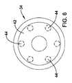
マンドレルの例は、第1端部と第2端部とその間に延びる本体部とを有する長尺状の部材からなり、
本体部は、長さに沿って延びるらせん状の第1溝を備え、
第1端部は、管状部材の第1端を固定する第1固定部を含む。An example of a mandrel consists of a long member having a first end, a second end, and a main body extending therebetween,
The main body includes a spiral first groove extending along the length,
The first end portion includes a first fixing portion that fixes the first end of the tubular member.
上記実施形態のいずれか1つに代替的に又は追加的に、第2端部は、管状部材の第2端部を固定する第2固定部を含む。
上記実施形態のいずれか1つに代替的に又は追加的に、第1固定部は、第1端部を貫通して延びる第1開口部を有し、第2固定部は、第2端部を貫通して延びる第2開口部を有し、第1開口部と第2開口部とは、その内部に管状部材の第1端部と第2端部とを固定することができる。Alternatively or additionally to any one of the above embodiments, the second end includes a second securing portion that secures the second end of the tubular member.
Alternatively or additionally to any one of the above embodiments, the first securing portion has a first opening extending through the first end, and the second securing portion is the second end. The first opening and the second opening can fix the first end and the second end of the tubular member therein.
上記実施形態のいずれか1つに代替的に又は追加的に、マンドレルは、らせん状の第2溝と、らせん状の第1溝と第2溝との間に配置された連続性隆起部とを備え、連続性隆起部は、第1端部から第2端部まで本体部の長さに沿って延びる。 Alternatively or additionally to any one of the above embodiments, the mandrel includes a spiral second groove and a continuous ridge disposed between the spiral first groove and the second groove. And the continuous ridge extends along the length of the body from the first end to the second end.
いくつかの実施形態についての上記概要は、開示した実施形態の各実施形態、または本願発明の全ての実施内容を説明することを意図したものではない。以下の図面および詳細な説明では、より詳細に上記実施形態の実例を挙げる。 The above summary of some embodiments is not intended to describe each disclosed embodiment or every implementation of the present invention. The following drawings and detailed description give examples of the above embodiments in more detail.
本願発明は、添付の図面と共に以下の発明の詳細な説明を考慮することにさらに完全に理解することができる。 The present invention can be more fully understood upon consideration of the following detailed description of the invention in conjunction with the accompanying drawings.
本願発明は、様々な変更形態と代替形態とが可能であり、それらのうちの特別なものが例示することを目的として図面に示され、かつ詳細に説明されている。しかしながら、これは、本願発明を説明する特定の実施形態に限定することを意図したものではない。むしろ、その意図は、本願発明の主旨および範囲に入る全ての変更形態と均等形態と変化形態とを包含させることにある。 The present invention is capable of various modifications and alternative forms, of which specific ones are shown in the drawings and have been described in detail for purposes of illustration. However, this is not intended to limit the invention to the specific embodiments that illustrate the invention. Rather, the intent is to include all modifications, equivalents and variations that fall within the spirit and scope of the invention.
以下の定義された用語に関して、これらの定義は、請求項または本明細書において異なる定義が与えられない限り、適用されるものとする。
全ての数値は、明示的に示されているか否かに拘わらず、「約」という用語で修飾されることが想定されている。「約」という用語は、一般的には、例えば、同じ機能または効果をもたらすなど、当業者が、記載された値に均等であると考える数値範囲のことを言う。多くの場合において、「約」という用語には、最も近い有効数字に四捨五入される複数の数値が含まれる。For the following defined terms, these definitions shall be applied, unless a different definition is given in the claims or herein.
All numerical values are assumed to be modified with the term “about”, whether or not explicitly indicated. The term “about” generally refers to a range of values that one of ordinary skill in the art believes to be equivalent to the recited value, such as, for example, providing the same function or effect. In many cases, the term “about” includes a plurality of numbers that are rounded to the nearest significant figure.
終点によって記載される数値範囲には、その範囲に入る全ての数値が含まれる(例えば、1〜5には、1,1.5,2,2.75,3,3.80,4,5が含まれる)。
本明細書および添付の請求項で使用するように、「a」、「an」、「the」は、明示の記載がない限り、複数の指示対象を含む。本明細書及び添付の請求項で使用するように、明示の記載がない限り、「または」は、一般的に「および/または」を含む意味で使用する。The numerical range described by the end point includes all numerical values falling within the range (for example, 1 to 5 includes 1, 1.5, 2, 2.75, 3, 3.80, 4, 5 Included).
As used herein and in the appended claims, “a”, “an”, and “the” include plural referents unless explicitly stated. As used herein and in the appended claims, the use of “or” generally includes “and / or” unless stated otherwise.
本明細書の「実施形態」、「いくつかの実施形態」、「その他の実施形態」は、1つ以上の特定の要素、構造体、および特徴のうちの少なくともいずれか1つを含む実施形態を示すものとする。しかしながら、このような記載は、全ての実施形態が、特定の要素、構造体、および特徴のうちの少なくともいずれか1つを備えることを必ずしも意味していない。加えて、特定の要素、構造体、および特徴のうちの少なくともいずれか1つが、一実施形態と関連付けて説明される場合には、そのような要素、構造体、および特徴のうちの少なくともいずれか1つは、反対のことが明確に記載されていない限り、明示の記載の有無に拘わらず、別の実施形態と関連付けて使用することもできる。 As used herein, “embodiments”, “some embodiments”, “other embodiments” are embodiments that include at least one of one or more particular elements, structures, and features. It shall be shown. Such a description, however, does not necessarily mean that all embodiments comprise at least one of the specific elements, structures, and features. In addition, where at least one of a particular element, structure, and feature is described in connection with one embodiment, at least one of such element, structure, and feature One can also be used in conjunction with another embodiment, with or without express statement, unless the contrary is explicitly stated.
以下の詳細な説明は、図面を参照して読まれたい。異なる図面の類似する要素には同じ符号が付されている。図面は、必ずしも縮尺通りではないが、例示の実施形態を示すものであり、本願発明の範囲を限定することを意図したものではない。 The following detailed description should be read with reference to the drawings. Similar elements in different drawings bear the same reference numerals. The drawings are not necessarily to scale, but illustrate exemplary embodiments and are not intended to limit the scope of the invention.
がんなどの異常な組織成長の治療は、様々な方法を用いて行われる。例えば、がんの治療には、罹患組織を横切ってステントを配置し、かつ展開することが含まれる。しかしながら、ステント処置の効果は、1つ以上の従来の治療を組み合わせることによって改善しうる。例えば、ステントの配置と放射線療法とを組み合わせることで、ステント単独あるいは放射線治療単独の場合と比べてがん治療の効果を向上させることができる。したがって、従来のステント法と放射線治療とを組み合わせる材料を用いること、およびステントを設計することのうちの少なくともいずれか一方が求められている。ここに開示する例および方法には、放射線治療を実施することができるステントが含まれる。 Treatment of abnormal tissue growth, such as cancer, is performed using a variety of methods. For example, treatment of cancer includes placing and deploying a stent across the affected tissue. However, the effectiveness of stent treatment can be improved by combining one or more conventional therapies. For example, by combining the placement of the stent and radiation therapy, the effect of cancer treatment can be improved as compared to the case of stent alone or radiation treatment alone. Therefore, there is a need for at least one of using materials that combine conventional stenting and radiation therapy and designing stents. Examples and methods disclosed herein include stents capable of performing radiation therapy.
ここに開示するステントは、食道がんを治療する。これに加えて、本ステントは、胃腸系、膵臓、大腸、気管支、尿道、尿管、心臓、脳、胸部、膀胱、椎体形成術、および末梢血管疾患などの、他の疾患(例えば、がん)も治療しうる。さらに、ここに開示するステントは、中実性および中空性器官のうちの少なくともいずれか一方の切除腔内でも使用することができる。 The stent disclosed herein treats esophageal cancer. In addition to this, the stent may be used in other diseases (eg, Can also be treated. Furthermore, the stent disclosed herein can be used in the resection cavity of at least one of solid and hollow organs.
図1は、放射性ステント10の一例を示した図である。ステント10は、様々な異なる設計で配置された複数のフィラメントおよび筋交い部材12および拡張可能な骨組みを形成する幾何学パターンのうちの少なくとも1つを備える。例えば、筋交い部材12は、単一の管状部材からレーザー切断される。別例では、フィラメント12は、編組まれ、紡まれ、織られ、またはこれらまたは類似する製造技術の組み合わせを用いて形成される。したがって、ステントのセル開口部、筋交いの厚さ、筋交いの設計、ステントのセルの形状に関して、多数の設計やパターンや構成が考えられ、ここに開示する実施形態と共に使用される。加えて、図1に示したように、ステント10は、第1フレア端部と第2フレア端部とを有する。 FIG. 1 is a view showing an example of a
さらに、ステント10は、ステント搬送システム(図示略)を介して治療部位に搬送される。例えば、いくつかの例では、ステント10は、バルーン状の拡張可能なステントである。バルーン状の拡張可能なステントは、1個の円筒状の管状部材から形成される(例えば、円筒状の管状部材は、拡張可能なステント10を形成する為にレーザー切断される)。 Furthermore, the
別例では、ステント10は、自己展開性ステントである。自己展開性ステントは、自己展開性ステント搬送システムを介して治療部位に搬送される。ここに開示する例は、レーザー切断されたステントおよび編組ステントのうちの少なくともいずれか一方などのバルーン状の拡張可能なステント、自己展開性ステント、非拡張性ステント、またはその他のステントを含む様々なステント構成のうちの任意の1つと共に使用される。 In another example, the
図1には、1つ以上の管状部材18を含むステント10が示されている。管状部材18は、管状部材18に対して連結されることおよび取り付けられることのうちの少なくともいずれか一方にされた放射性要素の1つ以上を含む。放射性要素20は、1つ以上の間隙によって互いから離間されている(図示略)。以下でさらに詳細に説明するが、管状部材18は、ステント10に沿って、らせん状に延びる。図1は、ステント10の全長に沿って延びる管状部材18を示している(例えば、両フレア端部の間のステント部分に加えて両フレア端部に沿って延びている)。しかしながら、別例では、管状部材18は、ステント10の一部のみに延びる。 FIG. 1 shows a
いくつかの実施例では、ステント10は、自己展開性ステントである。自己展開性ステントの例は、堅固および半堅固なステント構造体を形成する為に組み合わされた1本以上のフィラメントを有する拡張可能な骨組みを含む。例えば、ステントフィラメント12は、拡張可能な骨組みを形成する為に、編組まれ、紡がれ、織合わされ、編まれ、または織られる。自己展開性ステントは、レーザー切断された1本の円筒状の管状ニチノール部材から形成される。 In some embodiments,
ここに開示する例に係るステントフィラメント12と管状部材18とを含むステント10は、様々な材料から形成しうる。例えば、自己展開性またはバルーン状に拡張可能なステント10は、ニチノールなどの金属から形成される。別例では、ステント10は、PETなどのポリマー材料から形成される。さらに別例では、ステント10は、金属材料とポリマー材料の組み合わせから形成される。加えて、ステント10は、生体吸収性および生分解性材料を含みうる。 The
ここに開示する少なくともいくつかの例では、ステント10は、被覆14を含む。例えば、フィラメント12および管状部材18の少なくともいずれか一方は、エラストーマ(elastomeric)材料または非エラストーマ(non-elastomeric)材料で部分的にまたは全体的に被覆される。加えて、フィラメント12および管状部材18のうちの少なくともいずれか一方は、シリコーンまたはePTFEなどのポリマー材料で部分的にまたは全体的に被覆される。さらには、ポリマーなどの被覆14は、ステント10の壁内の間隙、例えば、開口部やセルなどを跨ぐ。以下にさらに詳細に説明するが、被覆14は、ステント10の内部表面および外部表面の少なくともいずれか一方に対して噴出すること、浸漬すること、スピニングすること、またはポリマー性シートまたはチューブを取り付けることによって施される。いくつかの例では、被覆14は、ステントフィラメント12、管状部材18、またはステントフィラメント12と管状部材18の両方に対して施される。さらに、いくつかの実施例では、被覆14は、1つ以上のステントフィラメント12と1つ以上の管状部材18との組み合わせを覆う。例えば、いくつかの実施形態では、被覆14は、管状部材18をフィラメント12に対して取り付けるように構成される。In at least some examples disclosed herein, the
少なくとも一実施例では、ステント10のフィラメント12は、放射性材料を含むように設計される。例えば、図1では、放射性シード20などの放射性材料を搬送するように(例えば、包含する、または含むように)設計された中空部分を備える。いくつかの実施例では、1つ以上のフィラメント12の中心は、フィラメントの全長に亘って中空性である。シード20などの放射性材料は、フィラメント12がステント10に形成される(例えば、編組まれ、巻かれる)前に、フィラメント12に搭載される。別の実施例では、シード20などの放射性材料は、ステント10が標的部位に搬送される直前に中空性フィラメント12に搭載される。 In at least one embodiment, the
放射性シード20は、様々な放射性材料や様々な材料の組み合わせを含む。例えば、シード20は、ヨウ素‐125(例えば、GE Oncura THINSeed(登録商標)、IsoAid社のIsoAid Advantag(登録商標)、Best(登録商標)Iodine-125など)、パラジウム‐103(例えば、CivaTech Technology社のCivaString(登録商標)、Theragenics社のTheraseed(登録商標)、Best(登録商標)Palladium-103など)、セシウム‐131、金‐198、イリジウム−192およびイッテルビウム−169、またはその他の物、およびこれらの派生物のうちの少なくともいずれか1つである。さらには、シード20は、他の種類の放射性材料であってもよい。加えて、シード20は、β線を放射する放射性核種であってもよい。 The
一般的には、シード20は、標的部位に隣接して配置されて、放射性エネルギーおよび材料の少なくともいずれかい一方を放出することにより標的部位を放射性に治療する。シード20は、一般的には図1に示した形状をしている。言い換えれば、シード20は、長尺状の円筒形である。しかしながら、別の形状も考えられる。例えば、シード20は、円形、卵形、直方体形、三角形などであってもよい。シード20は、管状部材18に沿って様々なパターンおよび分布のうちの少なくともいずれか一方で、間隔をあけて配置されることおよび分布されることのうちの少なくとも一方にされる。例えば、シード20は、スペーサーを用いて互いから間隔をあけて配置される。言い換えれば、管状部材18に沿ってシード20の特定の分布、間隔、および配置の少なくともいずれか1つを形成する為に、任意の数のスペーサーが、シード20の間に配置される。スペーサーと組みあわせて行うシード20の分布や配置は、具体的な設計検討に基づいて変更することが可能である。 In general, the
図2は、図1に示したステント例10の線X−Xに沿った横断面図である。図2に示したように、被覆14は、スンテントフィラメント12、管状部材18、またはステントフィラメント12と管状部材18の両方を覆う。加えて、いくつかの実施例では、被覆14は、ステントフィラメントの1つ以上と、管状部材18の1つ以上の組み合わせを覆う。例えば、いくつかの例では、被覆14は、管状部材18をフィラメント12に取り付けるように構成される。例えば、ここに説明する少なくともいくつかの実施形態では、被覆14は、拡張可能な骨組みを形成するフィラメント12および管状部材18のうちの少なくともいずれか1つに対して直接的に施される。さらに、いくつかの実施例では、被覆14は、拡張可能な骨組みなどのフィラメント12を管状部材18に対して結合、取り付け、連結、または繋ぎ止める為に使用される。いくつかの実施形態では、被覆14は、拡張可能な骨組み12と管状部材18の両方を含む網構造体、またはマトリックス構造体に類似する。 FIG. 2 is a cross-sectional view taken along line XX of the stent example 10 shown in FIG. As shown in FIG. 2, the
加えて、いくつかの実施例では、拡張可能な骨組み12および管状部材18の少なくともいずれか1つは、被覆14の内部に包囲されおよび封入されることのうちの少なくともいずれか一方にされる。言い換えれば、いくつかの実施例では、被覆14は、拡張可能な骨組み12および管状部材18のうちの少なくともいずれか一方の全表面をほぼ覆う。しかしながら、別例では、管状部材18およびフィラメント12などの拡張可能な骨組み12のうちの少なくともいずれか一方は、被覆14の内部に埋設される。本願発明の目的においては、埋設されるという用語は、管状部材18およびフィラメント12などの拡張可能な骨組み12のうちの少なくともいずれか一方が、被覆14によって部分的にまたは全体的に覆われることを表す。言い換えれば、いくつかの実施例では、管状部材18および拡張可能な骨組み12は、管状部材18および拡張可能な骨組み12のうちの少なくともいずれか一方の一部は被覆14に接するが、管状部材18および拡張可能な骨組み12のうちの少なくともいずれか一方の一部に隣接する部分は被覆14の上や被覆14から離間して延びるように(例えば、管状部材18の一部は、被覆14を欠く)被覆14内に埋設される。 In addition, in some embodiments, at least one of the
加えて、ステント10は、内部表面23と外部表面25とを備える。いくつかの実施例では、図2に示したように、管状部材18は、ステント10の内部表面23に沿ってフィラメント12に取り付けられる。加えて、上述したように、管状部材18の1つ以上は、管状部材18の内部、例えば管状部材18の中空部分の内部などに配置された1つ以上の放射性シード20を含む。 In addition, the
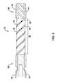
上述した放射性ステントを製造する工程の例を図3〜10を参照して説明する。図3は、被覆14を施す前に、管状部材18とフィラメント12とを互いに対して配置する為に設計されたマンドレル30の例を示す。図3に示したように、マンドレル30は、第1端部32と第2端部34と中間部(本体部)36とを備える。本体部36は、マンドレル30の外表面周囲にらせん状に延びる1つ以上のチャネルおよび溝38の少なくともいずれか一方を備える。図3では、溝38は、マンドレル30周囲にらせん状に延びているが、溝38は、マンドレル30周囲に別の配置、または方位に構成されてもよい。例えば、溝38は、本体36の長軸に沿って、直すぐに、例えば、互いに並行をなして延びてもよい。 An example of a process for manufacturing the above-described radioactive stent will be described with reference to FIGS. FIG. 3 shows an example of a
マンドレル30は、マンドレル30の外側表面周囲に延びる1つ以上の溝38を備えるように設計される。例えば、溝38は、マンドレル30に沿って、らせん状に延びる一本の、または連続したチャネルである。しかしながら、別の実施例では、溝38は、互いに並行をなす2、3、4、5、6、7、8、9、10本またはそれ以上の数の独立した溝を有する場合もある。例えば、図3には、互いに並行に回転する6本の独立した溝38が示されている。 The
加えて、いくつかの実施例では、マンドレル30は、同じ方向にらせん状になった2つ以上の溝38を含む。さらに、マンドレル38は、同じ方向に回転して進む溝38のみを含む。言い換えれば、マンドレル30は、互いに対して逆方向にらせん状になった溝を含まない。 In addition, in some embodiments, the
しかしながら、別例では、マンドレル30は、逆方向にらせん状になった複数の溝38を備える。例えば、マンドレル30は、各溝が互いに対して逆向きのらせんとして構成された2つ以上の溝38を含む。 However, in another example, the
加えて、マンドレル30は、同じ方向に回転して進み互いにほぼ等間隔で配置された複数のらせん状の溝38を含む。加えて、溝38は、複数の溝の間に配置された連続性隆起部41を備える。連続性隆起部は、第1端部32から第2端部34まで本体36の長さに沿って延びる。別例では、例えば、溝38がマンドレル30の全長に亘って延びている場合などでは、連続性隆起部41は、マンドレルの全長に亘って延びる。 In addition, the
以下にさらに詳細に説明するが、第1端部32と第2端部34とは、それぞれ、第1固定部と第2固定部を備える。固定部は、被覆14を施す前に管状部材18を配置するのを支援する様々な構造体を形成する。言い換えれば、固定部は、被覆14を施す前にマンドレル30に対して、管状部材18の一部、例えば、管状部材18の一端、または両端を固定する。 As will be described in more detail below, the
様々な固定機構が、以下の例で説明する固定機構に加えて想定される。例えば、いくつかの実施例では、第1端部32、および第2端部34のうちの少なくともいずれか一方は、マンドレル30に対して管状部材18を固定する為に、クリップ、ポスト、連結部、繋留具、フック、チャネル、溝、接着剤またはこれらの任意の組み合わせを備える。 Various fixing mechanisms are envisioned in addition to the fixing mechanisms described in the examples below. For example, in some embodiments, at least one of the
例えば、図4Aは、溝38と溝38の内部に配置された管状部材18の例とを示すマンドレル30の断面図である。図4Aに示した横断面は、マンドレル30の任意の部分に沿って得られる横断面であると考えられる。例えば、図4Aに示した固定機構は、マンドレル30の本体部36、および第1端部32、および第2端部34のうちの少なくともいずれか1つの上にある溝38を表す。For example, Figure 4A is a cross-sectional view of the
図4Aは、管状部材18の一部が溝38の内部に固定性に配置されつつ、管状部材18の一部が、マンドレル30の外表面を超えて(例えば、離間して)延びるように溝38の内部に配置される固定機構の例を示したものである。図4Aには、溝38が、マンドレル30の外表面に形成する開口部の寸法を定義する直径D1が示されている。図4Aには、さらに、溝38の内部に部分的に配置された管状部材18の直径を定義するD2も示されている。図4Aに示されているように、D2はD1より小さいため、管状部材18は、溝38の内部に固定されると解される。 FIG. 4A illustrates the groove such that a portion of the
図4Bは、管状部材18の一部が、マンドレル30の外表面を超えて延びないように溝38内部に配置される固定機構の例を示したものである。言い換えれば、図4Bは、管状部材18が、マンドレル30の外表面から径方向内方に完全に配置される例である。マンドレル30の外表面の内方に管状部材18を配置することによって、管状部材18は、マンドレル30の外表面に施された被覆の内部に完全に覆われて埋設されると考えられる。溝38は、管状部材18がマンドレル30の外表面の径方向内方に位置する直径、またはマンドレル30の外表面と同一平面をなす直径、若しくはマンドレル30の外表面から径方向に延びる直径、を有しうると考えられる。 FIG. 4B shows an example of a fixing mechanism in which a part of the
別例では、図3は、第1端部32を貫通して延びる複数の第1端部チャネル40を示す。第1端部チャネル40は、本体部36に沿って延びる溝38の延長である。言い換えれば、遠位端チャネルは、各溝38と1対1の関係で並ぶ。図7でさらに詳細に説明するが、ステント10を製造する方法では、管状部材18は、溝38に沿って移動される前に第1端チャネル40を通って移動される。言い換えれば、遠位端チャネルは、各溝38の中に、管状部材38をガイドすること、配置すること、および送り込むことのうちの少なくともいずれか1つを行う。 In another example, FIG. 3 shows a plurality of
加えて、図3は、第2端部34を貫通して延びる複数の第2端部チャネル44を示す。上述した遠位端チャネル38と同様に、第2端部チャネル44は、本体部36に沿って延びる溝38の延長である。言い換えれば、第2端チャネル44は、各溝38と1対1の関係で並ぶ。図8でさらに詳細に説明するが、ステント10を製造する方法において、管状部材18は、溝38に沿って移動された後、第1端部チャネル40に沿って移動される。 In addition, FIG. 3 shows a plurality of
図3は、第2端部34から離間して延びる取り付け部材42をさらに示す。取り付け部材42は、製造工程において、マンドレル30を固定、または保持する為に使用される。例えば、図11でさらに詳細に説明するが、取り付け部材42は、浸漬被覆工程で使用される。 FIG. 3 further illustrates a mounting
図5は、第1端部チャネル40を含むマンドレル30の第1端部32の端面図である。上述したように、図5には、6つの第1端部チャネル40を含むマンドレル30を示されているが、6つより多い数、または少ない数の遠位端部チャネルを含むことも可能である。図5に示したように、第1端部チャネル40は、第1端部32を貫通して延びる。言い換えれば、第1端部チャネル40は、第1端部32を貫通して延びる孔、および内腔のうちの少なくともいずれか一方として形成される。 FIG. 5 is an end view of the
図6は、第2端部44チャネルを含むマンドレル30の第2端部34の端面図である。上述したように、図6には、6つの第2端部チャネル44を含むマンドレル30が示されているが、6つより多い数、または少ない数の遠位端部チャネルを含むことも可能である。図6に示したように、第2端部チャネル44は、第2端部34を貫通して延びる。言い換えれば、第2端部チャネル44は、第2端部34を貫通して延びる孔、および内腔のうちの少なくともいずれか一方として形成される。 FIG. 6 is an end view of the
図7〜9は、ステント10を製造する方法の例を示したものである。図7に示したように、ステント10を製造する第1工程は、第1端部32の内部に配置された第1端部チャネル40を通って管状部材18を移動することを含む。管状部材18が移動する方向は、図7に矢印で示されている。図7には、第1端部チャネル40が、第1端部32の外表面から第1端部32を通って移動さ
れること、および第1端部チャネル40が本体部36の各溝38に一致することも示されている。7 to 9 show an example of a method for manufacturing the
溝38は、管状部材18を受承する寸法にされる。例えば、図8には、ステント10を製造する第2工程が、本体部36に配置された溝38に沿って管状部材18を移動することを含むことが示されている。上述し図8に示したように、溝38は、マンドレル30の外表面周囲にらせん状に配置される。図8には、管状部材が、溝38に一致する第1端部チャネル40を通って移動されることがさらに示されている。図8には、矢印で示したように、管状部材18が第1端部32から第2端部34に向かってらせん状の溝38に沿って移動されることがさらに示されている。溝38の寸法によって、管状部材18の一部は、マンドレル30の図3に示した連続性隆起部41上を延びることができると考えられる。別例では、管状部材18の外表面は、マンドレル30の外表面と同一平面に位置するか、あるいは少し下方に位置する。 The
図9は、外表面に沿って配置された管状部材18を含むマンドレル30上にフィラメント12で形成したステントなどの拡張可能な骨組み50を移動することを含むステント10を製造する第3工程を示したものである。図9には、管状部材が、第2端部チャネル44を貫通して移動されて、第2端部34から離間して延びていることが示されていることに留意されたい。ステント10を製造するこの工程では、管状部材18の一端部または両端部は、延びて第1端部チャネル40と第2端部チャネル44の内部で固定される。しかしながら、管状部材18は、第1端部チャネル40と第2端部チャネル44とを通って延びるがマンドレル30に固定された管状部材18の上を拡張可能な骨組み50を移動させる前に第1端部チャネル40と第2端部チャネル44の内部に固定されない。その上、いくつかの例では、拡張可能な骨組み50は、管状部材18が第2端部チャネル44を通って移動されて第2端部チャンネル44の内部に固定される前に、マンドレル30上を移動される。 FIG. 9 illustrates a third step of manufacturing a
図10は、上述したように、遠位および近位の端部チャネルを通って溝38に沿って移動された管状部材18の上に配置された拡張可能な骨組み50(例えば、フィラメント12から形成されたステントなど)を示した図である。図10に示したように、ステント部材の一部は、第1端部32と第2端部34の上に配置される。第1端部32と第2端部34とは、図1に示したステント10のフレア端部に対応すると考えられる。これに加えて、上述したように、管状部材18は、第1端部32と第2端部34とから離間して延びることが示されている。 FIG. 10 illustrates an expandable framework 50 (eg, formed from filament 12) disposed on
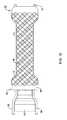
図11は、フィラメント12などの拡張可能な骨組み50と管状部材18の両方に対して図1で説明した被覆14を施す方法の例を示した図である。図11は、マンドレル30上に配置されたフィラメント12と管状部材18とに対して噴出54を行う噴出要素52を示している。噴出54は、フィラメント12の間のセルを通って通過するため、噴出54は、管状部材18に接することができる。例えば、上述したように、噴出54は、フィラメント12の内部表面と外部表面の両方の上、フィラメント12のセルの間、および管状部材18の全体または一部に沿って材料から成る層を形成する。いくつかの実施例では、被覆14は、拡張可能な骨組み50のセルの間の間隙腔をまたぐ。 FIG. 11 is a view showing an example of a method for applying the
上述したように、噴出54は、管状部材18および拡張可能な骨組み50のうちの少なくとも一方の全体または一部に施される被覆14に対応する。例えば、拡張可能な骨組み50は、管状部材18の上に配置されるため、被覆14は、管状部材18を拡張可能な骨組み50の内部表面に対して取り付けうる。さらに、図11に示したように、噴出要素52がマンドレル30の全長に亘って移動することにより、拡張可能な骨組み50および管状部材18の全体または一部に対して材料を配置しうる。マンドレル30、拡張可能な骨組み50、および管状部材18のうちの少なくともいずれか1つは、噴出54が施される際に回転されうる。 As described above, the
被覆14は、拡張可能な骨組み50の外表面に沿って施される(配置される)。別例では、被覆14は、拡張可能な骨組み50の内側表面上に配置されることが好ましい。さらに別例では、被覆14は、拡張可能な骨組み50の外側表面と内側表面の組み合わせに沿って配置するのが望ましい。いくつかの実施例では、被覆14は、管状部材18の外側表面および内側表面のうちの少なくともいずれか一方といった管状部材18の表面に対して施される。加えて、いくつかの実施例では、被覆14は、拡張可能な骨組み50、および管状部材18の少なくともいずれか一方の表面全体に亘って施されることが望ましい。更には、拡張可能な骨組み50、および管状部材18のうちの少なくともいずれか一方の任意の部分は、1つ以上の構造上の特徴の一部(例えば、フィラメント12および管状部材18の少なくともいずれか一方など)が、変化されないように、または比較的程度は小さいが変化されるように覆われると解される。 The
図12は、ステント10を製造する工程の別例を示した図である。図12は、ステント10に対して被覆14を施す際に浸漬被覆工程を用いる例である。図12に示したように、拡張可能な骨組み50、および管状部材18の少なくともいずれか一方を備えるステント10は、ステント10に対して被覆14を施すために容器56内に浸漬される(例えば、下降される)。容器56には、被覆14が含まれる。 FIG. 12 is a diagram showing another example of the process for manufacturing the
少なくともいくつかの実施形態では、被覆14を用いたステント10の浸漬被覆は、ステント10を容器56の内外に移動すること、およびステント10を容器56の内部で回転する間に行われる。例えば、ステント10は、ステント10を容器56に出し入れすることによって、またはステント10を容器56内で回転することによって、またはこれらの両方によって被覆される。しかしながら、いくつかの実施例では、回転と移動が必要とされない。いくつかの実施形態では、ステント10を移動、および回転するうちの少なくともいずれか一方の速度は、様々である。一般的に、移動速度、容器56内での時間、およびステント10を被覆14に浸漬する繰り返しはステント10に施す被覆14の量に対応する。さらに、フィラメント12および管状部材18の少なくともいずれか一方の任意の部分は、1つ以上の構造上の特徴部分、例えばフィラメント12および管状部材18のうちの少なくともいずれか一方などの部分が、変化されないように、または比較的程度は小さいが変化されるように覆われると解される。 In at least some embodiments, dip coating of the
ここで説明した例では、拡張可能な骨組み50の内側表面上にマンドレル30の本体部36に沿って配置された管状部材18が示されているが、管状部材18は、拡張可能な骨組み50の任意の部分に沿って配置されてマンドレル30の両端部まで延びうると解される。例えば、いくつかの実施例では、マンドレル30は、第1端部32、および第2端部34の表面のうちの少なくともいずれか一方の上に延びる溝38を含む。 In the example described here, the
いくつかの実施例では、マンドレル30を互いに分離することが可能な複数の構成部材から形成することが望ましい場合がある。例えば、いくつかの実施例では、第1端部32と第2端部34と本体部36とは、3つの独立した部材に分かれる。各部材は、ここで説明したマンドレル30を形成する為に、ねじ込み(screw)などによって連結される。 In some embodiments, it may be desirable to form the
ステント10、およびここで説明した様々な実施例の構成要素に用いられる材料には、医療装置に一般に関連するものが含まれる。簡潔化の為に、本開示は、ステント10に関してなされている。しかしながら、これは、ここで説明した装置及び用法を限定することを意図したものではなく、ここで開示したステントシステム、または装置の他の類似のシステムや構成要素にも適用することが可能である。 The materials used for the
多くの観点において、本願発明は、単なる例示であると理解されたい。本願発明の範囲を逸脱することなく、詳細、特に形状、寸法、および工程の順序に関して変更を加えることが可能である。これは、適切とされる程度において、ある実施例の任意の特徴を別の実施形態に使用することも含む。当然ながら、本願発明の範囲は、添付の請求項に記載された文言において定義される。 In many respects, the present invention should be understood to be merely exemplary. Changes may be made in details, particularly in terms of shape, dimensions, and process sequence, without departing from the scope of the present invention. This also includes the use of any feature of one example in another embodiment to the extent appropriate. Of course, the scope of the present invention is defined in the language recited in the appended claims.
Claims (6)
Translated fromJapanese拡張可能な骨組みを前記複数の管状部材と前記マンドレルの上に配置することと、
前記拡張可能な骨組みと前記複数の管状部材の両方に対して被覆を施すこと
と、からなるステントを製造する方法であって、
前記複数の管状部材を前記マンドレルの上に配置することは、前記複数の管状部材を前記マンドレルの表面に配置された溝に沿って巻きつけることを含む、ステントを製造する方法。Disposing a plurality of tubular members on a mandrel, each of the plurality of tubular members comprising a lumen extending therein;
Disposing an expandable skeleton over the plurality of tubular members and the mandrel;
Whereinthe arc applying a coating to both of the expandable framework and the plurality of tubular members <br/> andtoa method of producing a TonaLuztent,
Disposing the plurality of tubular members on the mandrel includes wrapping the plurality of tubular members along a groove disposed on a surface of the mandrel .
Applications Claiming Priority (5)
| Application Number | Priority Date | Filing Date | Title |
|---|---|---|---|
| US201562206236P | 2015-08-17 | 2015-08-17 | |
| US62/206,236 | 2015-08-17 | ||
| US201662355637P | 2016-06-28 | 2016-06-28 | |
| US62/355,637 | 2016-06-28 | ||
| PCT/US2016/047050WO2017031065A1 (en) | 2015-08-17 | 2016-08-15 | Radioactive stent |
Related Child Applications (1)
| Application Number | Title | Priority Date | Filing Date |
|---|---|---|---|
| JP2019156239ADivisionJP2020014861A (en) | 2015-08-17 | 2019-08-29 | Radioactive stent |
Publications (2)
| Publication Number | Publication Date |
|---|---|
| JP2018527987A JP2018527987A (en) | 2018-09-27 |
| JP6581292B2true JP6581292B2 (en) | 2019-09-25 |
Family
ID=57045382
Family Applications (2)
| Application Number | Title | Priority Date | Filing Date |
|---|---|---|---|
| JP2018508676AExpired - Fee RelatedJP6581292B2 (en) | 2015-08-17 | 2016-08-15 | Radioactive stent |
| JP2019156239APendingJP2020014861A (en) | 2015-08-17 | 2019-08-29 | Radioactive stent |
Family Applications After (1)
| Application Number | Title | Priority Date | Filing Date |
|---|---|---|---|
| JP2019156239APendingJP2020014861A (en) | 2015-08-17 | 2019-08-29 | Radioactive stent |
Country Status (7)
| Country | Link |
|---|---|
| US (1) | US20170049590A1 (en) |
| EP (1) | EP3337562B1 (en) |
| JP (2) | JP6581292B2 (en) |
| CN (1) | CN108136203A (en) |
| AU (1) | AU2016308055B2 (en) |
| CA (1) | CA2994294A1 (en) |
| WO (1) | WO2017031065A1 (en) |
Families Citing this family (8)
| Publication number | Priority date | Publication date | Assignee | Title |
|---|---|---|---|---|
| CN108778184B (en)* | 2016-03-07 | 2020-07-03 | 波士顿科学国际有限公司 | Esophageal stent including valve member |
| US20190274852A1 (en)* | 2018-03-12 | 2019-09-12 | Pfm Medical, Inc. | Bio-compatiple vascular implant |
| CN108742961B (en)* | 2018-04-04 | 2020-06-23 | 郑州大学第一附属医院 | An esophageal stent loaded with radioactive particles and with slow release function of chemotherapeutic liquid |
| CN110420079B (en)* | 2019-06-28 | 2022-03-08 | 深圳市先健畅通医疗有限公司 | Lumen Stents and Lumen Stent Systems |
| CN112932585B (en) | 2019-12-11 | 2023-01-03 | 先健科技(深圳)有限公司 | Left auricle plugging device |
| CN111249612B (en)* | 2020-03-20 | 2021-11-19 | 河南科技大学第一附属医院 | Radioactive source implantation device for vertebral tumor brachytherapy and radioactive source |
| CN115245634A (en)* | 2022-01-26 | 2022-10-28 | 温州医科大学附属第一医院 | Airway stent capable of carrying radioactive particles and method for making the same |
| CN115737226A (en)* | 2022-11-23 | 2023-03-07 | 深圳先进技术研究院 | Preparation method of cavity support |
Family Cites Families (26)
| Publication number | Priority date | Publication date | Assignee | Title |
|---|---|---|---|---|
| US5059166A (en)* | 1989-12-11 | 1991-10-22 | Medical Innovative Technologies R & D Limited Partnership | Intra-arterial stent with the capability to inhibit intimal hyperplasia |
| DK0441516T3 (en)* | 1990-02-08 | 1995-06-12 | Howmedica | Inflatable catheter |
| US5713949A (en)* | 1996-08-06 | 1998-02-03 | Jayaraman; Swaminathan | Microporous covered stents and method of coating |
| US5871436A (en)* | 1996-07-19 | 1999-02-16 | Advanced Cardiovascular Systems, Inc. | Radiation therapy method and device |
| US6174329B1 (en)* | 1996-08-22 | 2001-01-16 | Advanced Cardiovascular Systems, Inc. | Protective coating for a stent with intermediate radiopaque coating |
| ZA9710342B (en)* | 1996-11-25 | 1998-06-10 | Alza Corp | Directional drug delivery stent and method of use. |
| US5980551A (en)* | 1997-02-07 | 1999-11-09 | Endovasc Ltd., Inc. | Composition and method for making a biodegradable drug delivery stent |
| US6419621B1 (en)* | 1997-10-24 | 2002-07-16 | Radiomed Corporation | Coiled brachytherapy device |
| US6273908B1 (en)* | 1997-10-24 | 2001-08-14 | Robert Ndondo-Lay | Stents |
| US6626939B1 (en)* | 1997-12-18 | 2003-09-30 | Boston Scientific Scimed, Inc. | Stent-graft with bioabsorbable structural support |
| US6488701B1 (en)* | 1998-03-31 | 2002-12-03 | Medtronic Ave, Inc. | Stent-graft assembly with thin-walled graft component and method of manufacture |
| CA2345669C (en)* | 1998-09-30 | 2008-04-08 | Impra, Inc. A Subsidiary Of C.R. Bard, Inc. | Selective adherence of stent-graft coverings, mandrel and method of making stent-graft device |
| DE19913978A1 (en)* | 1999-03-18 | 2000-09-28 | Schering Ag | Asymmetric stent containing irregularly distributed active agents or radioisotopes useful e.g. for treating atherosclerosis and preventing restenosis |
| US6192271B1 (en)* | 1999-04-20 | 2001-02-20 | Michael Hayman | Radiotherapy stent |
| US20020055768A1 (en)* | 1999-11-24 | 2002-05-09 | Kathy Hess | Method of manufacturing a thin-layered, endovascular, polymer-covered stent device |
| US6251136B1 (en)* | 1999-12-08 | 2001-06-26 | Advanced Cardiovascular Systems, Inc. | Method of layering a three-coated stent using pharmacological and polymeric agents |
| US7318944B2 (en)* | 2003-08-07 | 2008-01-15 | Medtronic Vascular, Inc. | Extrusion process for coating stents |
| US8834338B2 (en)* | 2005-02-10 | 2014-09-16 | Snip Holdings, Inc. | Dosimetry implant for treating restenosis and hyperplasia |
| EP1887974B1 (en)* | 2005-05-13 | 2018-04-25 | Boston Scientific Limited | Integrated stent repositioning and retrieval loop |
| US8151682B2 (en)* | 2009-01-26 | 2012-04-10 | Boston Scientific Scimed, Inc. | Atraumatic stent and method and apparatus for making the same |
| EP2241284B1 (en)* | 2009-04-15 | 2012-09-19 | National University of Ireland, Galway | Intravasculature devices and balloons for use therewith |
| DE102011012501A1 (en)* | 2011-02-25 | 2012-08-30 | Phenox Gmbh | Implant with fiber fleece |
| US20140379069A1 (en)* | 2012-01-30 | 2014-12-25 | Hipokrat | Negatively charged vascular stent |
| EP2887994B1 (en)* | 2012-08-24 | 2019-02-20 | Boston Scientific Corporation | Device for improving brachytherapy |
| CN203369998U (en)* | 2013-06-27 | 2014-01-01 | 河南科技大学 | Self-stretching esophagus inner support capable of carrying radioactive elements to conduct local radiotherapy |
| GB2521045A (en)* | 2013-11-06 | 2015-06-10 | Bcm Co Ltd | Method of manufacturing stent attached to artificial blood vessel and stent attached to artificial blood vessel manufactured by the same |
- 2016
- 2016-08-15JPJP2018508676Apatent/JP6581292B2/ennot_activeExpired - Fee Related
- 2016-08-15WOPCT/US2016/047050patent/WO2017031065A1/ennot_activeCeased
- 2016-08-15AUAU2016308055Apatent/AU2016308055B2/ennot_activeCeased
- 2016-08-15CNCN201680060092.XApatent/CN108136203A/enactivePending
- 2016-08-15CACA2994294Apatent/CA2994294A1/ennot_activeAbandoned
- 2016-08-15EPEP16775007.4Apatent/EP3337562B1/ennot_activeNot-in-force
- 2016-08-15USUS15/237,147patent/US20170049590A1/ennot_activeAbandoned
- 2019
- 2019-08-29JPJP2019156239Apatent/JP2020014861A/enactivePending
Also Published As
| Publication number | Publication date |
|---|---|
| JP2018527987A (en) | 2018-09-27 |
| WO2017031065A1 (en) | 2017-02-23 |
| EP3337562B1 (en) | 2019-07-24 |
| CN108136203A (en) | 2018-06-08 |
| AU2016308055B2 (en) | 2019-02-14 |
| CA2994294A1 (en) | 2017-02-23 |
| US20170049590A1 (en) | 2017-02-23 |
| AU2016308055A1 (en) | 2018-02-22 |
| JP2020014861A (en) | 2020-01-30 |
| EP3337562A1 (en) | 2018-06-27 |
Similar Documents
| Publication | Publication Date | Title |
|---|---|---|
| JP6581292B2 (en) | Radioactive stent | |
| US10543379B2 (en) | Radioactive stents | |
| US6436026B1 (en) | Flexible, continuous, axially elastic interstitial brachytherapy source | |
| JP5563049B2 (en) | Expandable proximity irradiation device | |
| US6149574A (en) | Dual catheter radiation delivery system | |
| US5782742A (en) | Radiation delivery balloon | |
| JP2011156373A (en) | Method and device for delivery of therapeutic agent in conjunction with isotope seed placement | |
| JP7408670B2 (en) | Light irradiation medical device | |
| KR20020023416A (en) | Radioactive source train | |
| AU2016308061B2 (en) | Radioactive stent | |
| US20180028836A1 (en) | Radioactive medical device | |
| WO2022022576A1 (en) | Intracavitary radiotherapy apparatus and use method thereof | |
| CN106512197B (en) | Radioactive lumen stent | |
| CN218793552U (en) | A linear plastic deformation radiation device | |
| ES2445177T3 (en) | Helical brachytherapy device | |
| CN115607821A (en) | Linear plastic deformation radiation device | |
| US20170340899A1 (en) | Radioactive stent | |
| MXPA99007084A (en) | Radiation delivery balloon |
Legal Events
| Date | Code | Title | Description |
|---|---|---|---|
| A621 | Written request for application examination | Free format text:JAPANESE INTERMEDIATE CODE: A621 Effective date:20180221 | |
| A131 | Notification of reasons for refusal | Free format text:JAPANESE INTERMEDIATE CODE: A131 Effective date:20181106 | |
| A521 | Request for written amendment filed | Free format text:JAPANESE INTERMEDIATE CODE: A523 Effective date:20190206 | |
| A131 | Notification of reasons for refusal | Free format text:JAPANESE INTERMEDIATE CODE: A131 Effective date:20190312 | |
| A521 | Request for written amendment filed | Free format text:JAPANESE INTERMEDIATE CODE: A523 Effective date:20190612 | |
| TRDD | Decision of grant or rejection written | ||
| A01 | Written decision to grant a patent or to grant a registration (utility model) | Free format text:JAPANESE INTERMEDIATE CODE: A01 Effective date:20190730 | |
| A61 | First payment of annual fees (during grant procedure) | Free format text:JAPANESE INTERMEDIATE CODE: A61 Effective date:20190829 | |
| R150 | Certificate of patent or registration of utility model | Ref document number:6581292 Country of ref document:JP Free format text:JAPANESE INTERMEDIATE CODE: R150 | |
| LAPS | Cancellation because of no payment of annual fees |