JP6579377B2 - Vehicle steering system - Google Patents
Vehicle steering systemDownload PDFInfo
- Publication number
- JP6579377B2 JP6579377B2JP2015233717AJP2015233717AJP6579377B2JP 6579377 B2JP6579377 B2JP 6579377B2JP 2015233717 AJP2015233717 AJP 2015233717AJP 2015233717 AJP2015233717 AJP 2015233717AJP 6579377 B2JP6579377 B2JP 6579377B2
- Authority
- JP
- Japan
- Prior art keywords
- turning angle
- vehicle speed
- steering
- motor
- turning
- Prior art date
- Legal status (The legal status is an assumption and is not a legal conclusion. Google has not performed a legal analysis and makes no representation as to the accuracy of the status listed.)
- Active
Links
Images


Classifications
- B—PERFORMING OPERATIONS; TRANSPORTING
- B62—LAND VEHICLES FOR TRAVELLING OTHERWISE THAN ON RAILS
- B62D—MOTOR VEHICLES; TRAILERS
- B62D5/00—Power-assisted or power-driven steering
- B62D5/04—Power-assisted or power-driven steering electrical, e.g. using an electric servo-motor connected to, or forming part of, the steering gear
- B62D5/0457—Power-assisted or power-driven steering electrical, e.g. using an electric servo-motor connected to, or forming part of, the steering gear characterised by control features of the drive means as such
- B62D5/0481—Power-assisted or power-driven steering electrical, e.g. using an electric servo-motor connected to, or forming part of, the steering gear characterised by control features of the drive means as such monitoring the steering system, e.g. failures
- B62D5/0487—Power-assisted or power-driven steering electrical, e.g. using an electric servo-motor connected to, or forming part of, the steering gear characterised by control features of the drive means as such monitoring the steering system, e.g. failures detecting motor faults
- B—PERFORMING OPERATIONS; TRANSPORTING
- B62—LAND VEHICLES FOR TRAVELLING OTHERWISE THAN ON RAILS
- B62D—MOTOR VEHICLES; TRAILERS
- B62D5/00—Power-assisted or power-driven steering
- B62D5/001—Mechanical components or aspects of steer-by-wire systems, not otherwise provided for in this maingroup
- B—PERFORMING OPERATIONS; TRANSPORTING
- B62—LAND VEHICLES FOR TRAVELLING OTHERWISE THAN ON RAILS
- B62D—MOTOR VEHICLES; TRAILERS
- B62D15/00—Steering not otherwise provided for
- B62D15/02—Steering position indicators ; Steering position determination; Steering aids
- B62D15/021—Determination of steering angle
- B62D15/0215—Determination of steering angle by measuring on the steering column
- B62D15/022—Determination of steering angle by measuring on the steering column on or near the connection between the steering wheel and steering column
- B—PERFORMING OPERATIONS; TRANSPORTING
- B62—LAND VEHICLES FOR TRAVELLING OTHERWISE THAN ON RAILS
- B62D—MOTOR VEHICLES; TRAILERS
- B62D15/00—Steering not otherwise provided for
- B62D15/02—Steering position indicators ; Steering position determination; Steering aids
- B62D15/021—Determination of steering angle
- B62D15/0235—Determination of steering angle by measuring or deriving directly at the electric power steering motor
- B—PERFORMING OPERATIONS; TRANSPORTING
- B62—LAND VEHICLES FOR TRAVELLING OTHERWISE THAN ON RAILS
- B62D—MOTOR VEHICLES; TRAILERS
- B62D5/00—Power-assisted or power-driven steering
- B62D5/001—Mechanical components or aspects of steer-by-wire systems, not otherwise provided for in this maingroup
- B62D5/005—Mechanical components or aspects of steer-by-wire systems, not otherwise provided for in this maingroup means for generating torque on steering wheel or input member, e.g. feedback
- B—PERFORMING OPERATIONS; TRANSPORTING
- B62—LAND VEHICLES FOR TRAVELLING OTHERWISE THAN ON RAILS
- B62D—MOTOR VEHICLES; TRAILERS
- B62D5/00—Power-assisted or power-driven steering
- B62D5/04—Power-assisted or power-driven steering electrical, e.g. using an electric servo-motor connected to, or forming part of, the steering gear
- B62D5/0409—Electric motor acting on the steering column
- B62D5/0412—Electric motor acting on the steering column the axes of motor and steering column being parallel
- B62D5/0415—Electric motor acting on the steering column the axes of motor and steering column being parallel the axes being coaxial
- B—PERFORMING OPERATIONS; TRANSPORTING
- B62—LAND VEHICLES FOR TRAVELLING OTHERWISE THAN ON RAILS
- B62D—MOTOR VEHICLES; TRAILERS
- B62D5/00—Power-assisted or power-driven steering
- B62D5/04—Power-assisted or power-driven steering electrical, e.g. using an electric servo-motor connected to, or forming part of, the steering gear
- B62D5/0418—Electric motor acting on road wheel carriers
- B—PERFORMING OPERATIONS; TRANSPORTING
- B62—LAND VEHICLES FOR TRAVELLING OTHERWISE THAN ON RAILS
- B62D—MOTOR VEHICLES; TRAILERS
- B62D5/00—Power-assisted or power-driven steering
- B62D5/04—Power-assisted or power-driven steering electrical, e.g. using an electric servo-motor connected to, or forming part of, the steering gear
- B62D5/0457—Power-assisted or power-driven steering electrical, e.g. using an electric servo-motor connected to, or forming part of, the steering gear characterised by control features of the drive means as such
- B62D5/046—Controlling the motor
- B—PERFORMING OPERATIONS; TRANSPORTING
- B62—LAND VEHICLES FOR TRAVELLING OTHERWISE THAN ON RAILS
- B62D—MOTOR VEHICLES; TRAILERS
- B62D5/00—Power-assisted or power-driven steering
- B62D5/04—Power-assisted or power-driven steering electrical, e.g. using an electric servo-motor connected to, or forming part of, the steering gear
- B62D5/0457—Power-assisted or power-driven steering electrical, e.g. using an electric servo-motor connected to, or forming part of, the steering gear characterised by control features of the drive means as such
- B62D5/0481—Power-assisted or power-driven steering electrical, e.g. using an electric servo-motor connected to, or forming part of, the steering gear characterised by control features of the drive means as such monitoring the steering system, e.g. failures
- B62D5/0484—Power-assisted or power-driven steering electrical, e.g. using an electric servo-motor connected to, or forming part of, the steering gear characterised by control features of the drive means as such monitoring the steering system, e.g. failures for reaction to failures, e.g. limp home
- B—PERFORMING OPERATIONS; TRANSPORTING
- B62—LAND VEHICLES FOR TRAVELLING OTHERWISE THAN ON RAILS
- B62D—MOTOR VEHICLES; TRAILERS
- B62D6/00—Arrangements for automatically controlling steering depending on driving conditions sensed and responded to, e.g. control circuits
- B—PERFORMING OPERATIONS; TRANSPORTING
- B62—LAND VEHICLES FOR TRAVELLING OTHERWISE THAN ON RAILS
- B62D—MOTOR VEHICLES; TRAILERS
- B62D6/00—Arrangements for automatically controlling steering depending on driving conditions sensed and responded to, e.g. control circuits
- B62D6/002—Arrangements for automatically controlling steering depending on driving conditions sensed and responded to, e.g. control circuits computing target steering angles for front or rear wheels
Landscapes
- Engineering & Computer Science (AREA)
- Chemical & Material Sciences (AREA)
- Combustion & Propulsion (AREA)
- Transportation (AREA)
- Mechanical Engineering (AREA)
- Physics & Mathematics (AREA)
- Mathematical Physics (AREA)
- Steering Control In Accordance With Driving Conditions (AREA)
- Power Steering Mechanism (AREA)
Description
Translated fromJapaneseこの発明は、左右の転舵輪を個別に転舵するための左右の転舵機構を含み、操向のために操作される操舵部材と左右の転舵機構とが機械的に結合されておらず、左右の転舵機構が左右の転舵モータによって個別に駆動される車両用操舵装置に関する。 The present invention includes a left and right steering mechanism for individually steering left and right steered wheels, and the steering member operated for steering and the left and right steering mechanisms are not mechanically coupled. The present invention relates to a vehicle steering apparatus in which left and right steering mechanisms are individually driven by left and right steering motors.
自動運転に代表される高度運転支援機能を成立させるとともに、エンジンルームのレイアウトの自由度向上を目的とした、中間シャフトを使用しないステア・バイ・ワイヤシステムの有効性が評価され始めている。そして、エンジンルームのレイアウトの更なる自由度向上を図るために、下記特許文献1,2に示すように、ラックアンドピニオン機構等を含むステアリングギヤ装置を使用せず、左右の転舵輪を個別の転舵アクチュエータで制御する左右独立転舵システムが提案されている。 The effectiveness of steer-by-wire systems that do not use an intermediate shaft for the purpose of establishing advanced driving support functions typified by automatic driving and improving the degree of freedom in engine room layout is beginning to be evaluated. And in order to further improve the degree of freedom in the layout of the engine room, as shown in
ステア・バイ・ワイヤシステムでは、実転舵角が目標転舵角に等しくなるように転舵モータがフィードバック制御される。そして、実転舵角に対する実転舵角の偏差が所定値以上になると、何らかの異常が発生したと判定して、フェール処理されるのが一般的である。フェール処理では、例えば、転舵モータが停止状態にされる。
この発明の目的は、新規な方法で異常が発生したか否かを判定できる車両用操舵装置を提供することである。In the steer-by-wire system, the steered motor is feedback-controlled so that the actual steered angle becomes equal to the target steered angle. When the deviation of the actual turning angle with respect to the actual turning angle is equal to or greater than a predetermined value, it is generally determined that some abnormality has occurred and is subjected to fail processing. In the fail process, for example, the steered motor is stopped.
An object of the present invention is to provide a vehicle steering apparatus that can determine whether or not an abnormality has occurred by a novel method.
請求項1に記載の発明は、左転舵輪(3L)および右転舵輪(3R)を個別に転舵するための左転舵機構(5L)および右転舵機構(5R)を含み、操向のために操作される操舵部材(2)と前記左転舵機構および右転舵機構とが機械的に結合されておらず、前記左転舵機構が左転舵モータ(4L)によって駆動され、前記右転舵機構が右転舵モータ(4R)によって駆動される車両用操舵装置(1)であって、前記左転舵輪の転舵角の目標値である左目標転舵角および前記右転舵輪の転舵角の目標値である右目標転舵角を設定する目標転舵角設定手段(42)と、前記左転舵輪の転舵角である左転舵角を取得する左転舵角取得手段(30)と、前記右転舵輪の転舵角である右転舵角を取得する右転舵角取得手段(30)と、前記左転舵角と前記左目標転舵角との差である左転舵角偏差が小さくなるように前記左転舵モータを制御する左モータ制御手段(43L〜49L,32L)と、前記右転舵角と前記右目標転舵角との差である右転舵角偏差が小さくなるように前記右転舵モータを制御する右モータ制御手段(43R〜49R,32R)と、前記左転舵角偏差と前記右転舵角偏差との差の絶対値が第1閾値以上になったときに、異常が発生したと判定する判定手段(50)とを含む、車両用操舵装置である。なお、括弧内の英数字は後述の実施形態における対応構成要素等を表すが、むろん、この発明の範囲は当該実施形態に限定されない。以下、この項において同じ。 The invention described in
この構成では、左転舵角偏差と右転舵角偏差との差の絶対値が第1閾値以上になったときに、異常が発生したと判定される。これにより、左転舵モータおよび右転舵モータのうちのいずれか一方が故障した場合や、左モータ制御手段または右モータ制御手段うちのいずれか一方に異常が発生した場合に、異常が発生したと判定することができる。
この構成によれば、両転舵モータおよびこれらの制御手段に異常がなく、路面の摩擦係数の増大、左右転舵輪のタイヤ空気圧の低下等によって、転舵モータのフィードバック制御の追従性が一時的に低下しただけである場合には、左転舵角偏差および右転舵角偏差は共に大きくなるため、異常が発生したと判定されにくい。これにより、転舵モータのフィードバック制御の追従性が一時的に低下しただけであるにも拘わらず、異常が発生したと誤判定されるのを抑制できる。In this configuration, it is determined that an abnormality has occurred when the absolute value of the difference between the left turning angle deviation and the right turning angle deviation is equal to or greater than the first threshold value. As a result, an abnormality occurred when either one of the left steering motor and the right steering motor failed or when an abnormality occurred in either the left motor control means or the right motor control means. Can be determined.
According to this configuration, there is no abnormality in both the turning motors and their control means, and the followability of the feedback control of the turning motors is temporarily caused by an increase in the friction coefficient of the road surface, a decrease in tire air pressure of the left and right turning wheels, etc. However, it is difficult to determine that an abnormality has occurred because both the left turning angle deviation and the right turning angle deviation increase. As a result, it is possible to suppress erroneous determination that an abnormality has occurred even though the follow-up performance of the feedback control of the steered motor has only temporarily decreased.
請求項2に記載の発明は、前記左転舵角偏差の時間変化率の絶対値および前記右転舵角偏差の時間変化率の絶対値の少なくとも一方が第2閾値未満となったときに、異常が発生したと判定する手段(50)をさらに含む、請求項1に記載の車両用操舵装置である。
請求項3に記載の発明は、前記左転舵角偏差の絶対値が第3閾値よりも大きくかつ前記左転舵角偏差の時間変化率の絶対値が第4閾値未満となったとき、または前記右転舵角偏差の絶対値が前記第3閾値よりも大きくかつ前記右転舵角偏差の時間変化率の絶対値が前記第4閾値未満となったときに、異常が発生したと判定する手段(50)をさらに含む、請求項1に記載の車両用操舵装置である。In the invention according to
When the absolute value of the left turning angle deviation is greater than a third threshold and the absolute value of the time change rate of the left turning angle deviation is less than the fourth threshold, or When the absolute value of the right turning angle deviation is larger than the third threshold value and the absolute value of the time change rate of the right turning angle deviation is less than the fourth threshold value, it is determined that an abnormality has occurred. The vehicle steering system according to
請求項4に記載の発明は、車速を取得する車速取得手段(30)と、前記車速取得手段によって取得された車速に応じて前記第1閾値を変更させる手段(51)とをさらに含む、請求項1〜3のいずれか一項に記載の車両用操舵装置である。
請求項5に記載の発明は、車速を取得する車速取得手段(30)と、前記車速取得手段によって取得された車速に応じて前記第1閾値を変更させる手段(51)と、前記車速取得手段によって取得された車速に応じて前記第2閾値を変更させる手段(51)とをさらに含む、請求項2に記載の車両用操舵装置である。The invention described in
The invention according to claim 5 is a vehicle speed acquisition means (30) for acquiring a vehicle speed, a means (51) for changing the first threshold according to the vehicle speed acquired by the vehicle speed acquisition means, and the vehicle speed acquisition means. The vehicle steering apparatus according to
請求項6に記載の発明は、車速を取得する車速取得手段(30)と、前記車速取得手段によって取得された車速に応じて前記第1閾値を変更させる手段(51)と、前記車速取得手段によって取得された車速に応じて前記第3閾値を変更させる手段(51)と、前記車速取得手段によって取得された車速に応じて前記第4閾値を変更させる手段(51)とさらに含む、請求項3に記載の車両用操舵装置である。 The invention according to claim 6 is a vehicle speed acquisition means (30) for acquiring a vehicle speed, a means (51) for changing the first threshold according to the vehicle speed acquired by the vehicle speed acquisition means, and the vehicle speed acquisition means. And means (51) for changing the third threshold value according to the vehicle speed acquired by the vehicle, and means (51) for changing the fourth threshold value according to the vehicle speed acquired by the vehicle speed acquisition means. The vehicle steering device according to
以下では、この発明の実施の形態を、添付図面を参照して詳細に説明する。
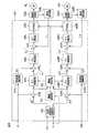
図1は、この発明の一実施形態に係る車両用操舵装置の構成を説明するための図解図であり、左右独立転舵システムが採用されたステア・バイ・ワイヤシステムの構成が示されている。
この車両用操舵装置1は、運転者が操向のために操作する操舵部材としてステアリングホイール2と、左転舵輪3Lおよび右転舵輪3Rと、ステアリングホイール2の回転操作に応じて駆動される左転舵モータ4Lおよび右転舵モータ4Rと、左転舵モータ4Lの駆動力に基づいて左転舵輪3Lを転舵する左転舵機構5Lと、右転舵モータ4Rの駆動力に基づいて右転舵輪3Rを転舵する右転舵機構5Rとを備えている。Hereinafter, embodiments of the present invention will be described in detail with reference to the accompanying drawings.
FIG. 1 is an illustrative view for explaining the configuration of a vehicle steering apparatus according to an embodiment of the present invention, and shows the configuration of a steer-by-wire system employing a left and right independent steering system. .
The
ステアリングホイール2と左転舵機構5Lおよび右転舵機構5Rとの間には、ステアリングホイール2に加えられた操舵トルクが左転舵機構5Lおよび右転舵機構5Rに機械的に伝達されるような機械的な結合はなく、ステアリングホイール2の操作量(操舵角または操舵トルク)に応じて左転舵モータ4Lおよび右転舵モータ4Rが駆動制御されることによって、左転舵輪3Lおよび右転舵輪3Rが転舵されるようになっている。左転舵機構5Lおよび右転舵機構5Rとしては、例えば、特許文献2に開示されたサスペンション装置や、特許文献1に開示された転舵装置を用いることができる。 Between the
この実施形態では、転舵モータ4L,4Rが正転方向に回転されると、右方向に車両を換向させる方向(右転舵方向)に転舵輪3L,3Rの転舵角が変化し、転舵モータ4L,4Rが逆転方向に回転されると、左方向に車両を換向させる方向(左転舵方向)に転舵輪3L,3Rの転舵角が変化するものとする。
ステアリングホイール2は、車体側に回転可能に支持された回転シャフト6に連結されている。この回転シャフト6には、ステアリングホイール2に作用する反力トルク(操作反力)を発生する反力モータ7が設けられている。この反力モータ7は、例えば、回転シャフト6と一体の出力シャフトを有する電動モータにより構成されている。In this embodiment, when the steered
The
回転シャフト6の周囲には、回転シャフト6の回転角(ステアリングホイール2の操舵角θh)を検出するための操舵角センサ8が設けられている。この実施形態では、操舵角センサ8は、回転シャフト6の中立位置(基準位置)からの回転シャフト6の正逆両方向の回転量(回転角)を検出するものであり、中立位置から右方向への回転量を例えば正の値として出力し、中立位置から左方向への回転量を例えば負の値として出力する。 A
また、回転シャフト6の周囲には、運転者によってステアリングホイール2に付与される操舵トルクThを検出するためのトルクセンサ9が設けられている。この実施形態では、トルクセンサ9によって検出される操舵トルクTは、右方向への操舵のためのトルクが正の値として検出され、左方向への操舵のためのトルクが負の値として検出され、その絶対値が大きいほど操舵トルクの大きさが大きくなるものとする。 A torque sensor 9 for detecting a steering torque Th applied to the
左転舵機構5Lの近傍には、左転舵輪3Lの転舵角δLを検出するための左転舵角センサ10Lが備えられている。右転舵機構5Rの近傍には、右転舵輪3Rの転舵角δRを検出するための右転舵角センサ10Rが備えられている。車両には、さらに、車速Vを検出するための車速センサ11が設けられている。
操舵角センサ8、トルクセンサ9および車速センサ11、左転舵角センサ10L、右転舵角センサ10R、左転舵モータ4L、右転舵モータ4Rおよび反力モータ7は、電子制御ユニット(ECU:Electronic Control Unit)30にそれぞれ接続されている。ECU30は、左転舵モータ4L、右転舵モータ4Rおよび反力モータ7を制御する。In the vicinity of the
The
図2は、ECU30の電気的構成を示すブロック図である。
ECU30は、マイクロコンピュータ31と、マイクロコンピュータ31によって制御され、左転舵モータ4Lに電力を供給する駆動回路(インバータ回路)32Lと、左転舵モータ4Lに流れるモータ電流を検出する電流検出部33Lとを含む。ECU30は、さらに、マイクロコンピュータ31によって制御され、右転舵モータ4Rに電力を供給する駆動回路(インバータ回路)32Rと、右転舵モータ4Rに流れるモータ電流を検出する電流検出部33Rとを含む。ECU30は、さらに、マイクロコンピュータ31によって制御され、反力モータ7に電力を供給する駆動回路(インバータ回路)34と、反力モータ7に流れるモータ電流を検出する電流検出部35とを含む。FIG. 2 is a block diagram showing an electrical configuration of the
The ECU 30 is controlled by the
マイクロコンピュータ31は、CPUおよびメモリ(ROM、RAM、不揮発性メモリなど)を備えており、所定のプログラムを実行することによって、複数の機能処理部として機能するようになっている。この複数の機能処理部には、左転舵モータ4Lの駆動回路32Lおよび右転舵モータ4Rの駆動回路32Rを制御するための転舵モータ制御部40と、反力モータ7の駆動回路34を制御するための反力モータ制御部60とを備えている。 The
反力モータ制御部60は、トルクセンサ9によって検出される操舵トルクTh、操舵角センサ8によって検出される操舵角θh、車速センサ11によって検出される車速Vおよび電流検出部35によって検出されるモータ電流に基づいて、反力モータ7の駆動回路34を駆動する。例えば、反力モータ制御部60は、操舵トルクTh、操舵角θhおよび車速Vに基づいて、反力モータ7に発生させるべき反力トルクの目標値である目標反力トルクを演算する。そして、反力モータ制御部60は、目標反力トルクに応じた反力トルクが反力モータ7から発生するように、反力モータ7の駆動回路34を駆動する。 The reaction force
転舵モータ制御部40は、操舵角センサ8によって検出される操舵角θh、車速センサ11によって検出される車速V、左転舵角センサ10Lおよび右転舵角センサ10Rによってそれぞれ検出される左転舵角δLおよび右転舵角δRならびに電流検出部33L,33Rによってそれぞれ検出されるモータ電流に基づいて、転舵モータ4L,4Rの駆動回路32L,32Rを駆動する。以下、転舵モータ制御部40について、詳しく説明する。The steered
図3は、転舵モータ制御部40の構成例を示すブロック図である。
転舵モータ制御部40は、角速度演算部41L,41Rと、目標転舵角設定部42と、転舵角偏差演算部43L,43Rと、PI制御部(転舵角)44L,44Rと、角速度偏差演算部45L,45Rと、PI制御部(角速度)46L,46Rと、電流偏差演算部47L,47Rと、PI制御部(電流)48L,48Rと、PWM(Pulse Width Modulation)制御部49L,49Rと、異常判定部50とを含む。FIG. 3 is a block diagram illustrating a configuration example of the steered
The steered
角速度演算部41Lは、左転舵角センサ10Lによって検出される左転舵角δLを時間微分することによって、左転舵角δLの角速度(左転舵角速度)ωLを演算する。角速度演算部41Rは、右転舵角センサ10Rによって検出される右転舵角δRを時間微分することによって、右転舵角δLの角速度(右転舵角速度)ωRを演算する。
目標転舵角設定部42は、操舵角θhおよび車速Vに基づいて、左転舵輪3Lの転舵角の目標値である左目標転舵角δL*と、右転舵輪3Rの転舵角の目標値である右目標転舵角δR*とを設定する。Angular
Target steering
転舵角偏差演算部43Lは、目標転舵角設定部42によって設定される左目標転舵角δL*と、左転舵角センサ10Lによって検出される左転舵角δLとの偏差ΔδL(=δL*−δL)を演算する。転舵角偏差演算部43Rは、目標転舵角設定部42によって設定される右目標転舵角δR*と、右転舵角センサ10Rによって検出される右転舵角δRとの偏差ΔδR(=δR*−δR)を演算する。The turning angle
PI制御部44Lは、転舵角偏差演算部43Lによって演算される左転舵角偏差ΔδLに対するPI演算を行なうことにより、左転舵角速度の目標値である左目標転舵角速度ωL*を演算する。PI制御部44Rは、転舵角偏差演算部43Rによって演算される右転舵角偏差ΔδRに対するPI演算を行なうことにより、右転舵角速度の目標値である右目標転舵角速度ωR*を演算する。The
角速度偏差演算部45Lは、PI制御部44Lによって演算される左目標転舵角速度ωL*と、角速度演算部41Lによって演算される左転舵角速度ωLとの偏差ΔωL(=ωL*−ωL)を演算する。角速度偏差演算部45Rは、PI制御部44Rによって演算される右目標転舵角速度ωR*と、角速度演算部41Rによって演算される右転舵角速度ωRとの偏差ΔωR(=ωR*−ωR)を演算する。Angular
PI制御部46Lは、角速度偏差演算部45Lによって演算される左転舵角速度偏差ΔωLに対するPI演算を行なうことにより、左転舵モータ4Lに流すべき電流の目標値である左目標モータ電流IL*を演算する。PI制御部46Rは、角速度偏差演算部45Rによって演算される右転舵角速度偏差ΔωRに対するPI演算を行なうことにより、右転舵モータ4Rに流すべき電流の目標値である右目標モータ電流IR*を演算する。The
電流偏差演算部47Lは、PI制御部46Lによって演算される左目標モータ電流IL*と、電流検出部33Lによって検出される左モータ電流ILとの偏差ΔIL(=IL*−IL)を演算する。電流偏差演算部47Rは、PI制御部46Rによって演算される右目標モータ電流IR*と、電流検出部33Rによって検出される右モータ電流IRとの偏差ΔIR(=IR*−IR)を演算する。Current
PI制御部48Lは、電流偏差演算部47Lによって演算される左モータ電流偏差ΔILに対するPI演算を行なうことにより、左転舵モータ4Lに流れる左モータ電流ILを左目標モータ電流IL*に導くための左モータ駆動指令値を生成する。PI制御部48Rは、電流偏差演算部47Rによって演算される右モータ電流偏差ΔIRに対するPI演算を行なうことにより、右転舵モータ4Rに流れる右モータ電流IRを右目標モータ電流IR*に導くための右モータ駆動指令値を生成する。
PWM制御部49Lは、左モータ駆動指令値に対応するデューティ比の左PWM制御信号を生成して、駆動回路32Lに供給する。これにより、左モータ駆動指令値に対応した電力が左転舵モータ4Lに供給されることになる。PWM制御部49Rは、右モータ駆動指令値に対応するデューティ比の右PWM制御信号を生成して、駆動回路32Rに供給する。これにより、右モータ駆動指令値に対応した電力が右転舵モータ4Rに供給されることになる。 The
転舵角偏差演算部43LおよびPI制御部44Lは、角度フィードバック制御手段を構成している。この角度フィードバック制御手段の働きによって、左転舵輪3Lの転舵角δLが、目標転舵角設定部42によって設定される左目標転舵角δL*に近づくように制御される。また、角速度偏差演算部45LおよびPI制御部46Lは、角速度フィードバック制御手段を構成している。この角速度フィードバック制御手段の働きによって、左転舵角速度ωLが、PI制御部44Lによって演算される左目標転舵角速度ωL*に近づくように制御される。また、電流偏差演算部47LおよびPI制御部48Lは、電流フィードバック制御手段を構成している。この電流フィードバック制御手段の働きによって、左転舵モータ4Lに流れるモータ電流ILが、PI制御部46Lによって演算される左目標モータ電流IL*に近づくように制御される。The turning angle
同様に、転舵角偏差演算部43RおよびPI制御部44Rは、角度フィードバック制御手段を構成している。この角度フィードバック制御手段の働きによって、右転舵輪3Rの転舵角δRが、目標転舵角設定部42によって設定される右目標転舵角δR*に近づくように制御される。また、角速度偏差演算部45RおよびPI制御部46Rは、角速度フィードバック制御手段を構成している。この角速度フィードバック制御手段の働きによって、右転舵角速度ωRが、PI制御部44Rによって演算される右目標転舵角速度ωR*に近づくように制御される。また、電流偏差演算部47RおよびPI制御部48Rは、電流フィードバック制御手段を構成している。この電流フィードバック制御手段の働きによって、右転舵モータ4Rに流れるモータ電流IRが、PI制御部46Rによって演算される右目標モータ電流IR*に近づくように制御される。Similarly, the turning angle
次に、異常判定部50の動作について詳しく説明する。
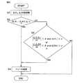
図4は、異常判定部50の動作を説明するためのフローチャートである。図4の処理は、所定の演算周期毎に繰り返し実行される。
異常判定部50は、転舵角偏差演算部43Lによって演算された左転舵角偏差ΔδLと、転舵角偏差演算部43Rによって演算された右転舵角偏差ΔδRとを取得する(ステップS1)。Next, the operation of the
FIG. 4 is a flowchart for explaining the operation of the
The
次に、異常判定部50は、次式(1)で示される第1条件を満たしているか否かを判別する。
|ΔδL−ΔδR|≧α …(1)
前記式(1)において、|ΔδL−ΔδR|は、左転舵角偏差ΔδLと右転舵角偏差ΔδRとの差の絶対値である。また、α(>0)は、予め設定された第1閾値である。後述するように、第1閾値αは、車速Vに応じて変更されてもよい。Next, the
| ΔδL −ΔδR | ≧ α (1)
In the equation (1), | ΔδL −ΔδR | is an absolute value of a difference between the left turning angle deviation ΔδL and the right turning angle deviation ΔδR. Α (> 0) is a preset first threshold value. As will be described later, the first threshold value α may be changed according to the vehicle speed V.
異常判定部50は、「左転舵角偏差ΔδLと右転舵角偏差ΔδRとの差の絶対値|ΔδL−ΔδR|が第1閾値α以上である」ときに第1条件を満たしていると判別する。例えば、左転舵モータ4Lおよび右転舵モータ4Rのうちのいずれか一方が故障した場合や、左転舵モータ4Lの制御系または右転舵モータ4Rの制御系のうちのいずれか一方に異常が発生した場合には、第1条件を満たすことになる。ただし、両転舵モータ4L,4Rおよびこれらの制御系に異常がなく、路面の摩擦係数の増大、左右転舵輪のタイヤ空気圧の低下等によって、フィードバック制御の追従性が一時的に低下しただけである場合には、ΔδLおよびΔδRは共に大きくなるため、第1条件は満たさない。
ステップS2において、第1条件を満たしていないと判別された場合(ステップS2:NO)、つまり、|ΔδL−ΔδR|がα未満である場合には、異常判定部50は、ステップS3に移行する。
ステップS3では、異常判定部50は、次式(2)で示される第2条件を満たしているか否かを判別する。In step S2, if it is determined not to satisfy the first condition (step S2: NO), i.e., | ΔδL -ΔδR | if is less than α, the
In step S <b> 3, the
|dΔδL/dt|<β and |ΔδL|>γ
or
|dΔδR/dt|<β and |ΔδR|>γ …(2)
前記式(2)において、|dΔδL/dt|は、左転舵角偏差ΔδLの時間微分値の絶対値であり、左転舵角偏差ΔδLの時間変化率の絶対値を表している。|dΔδR/dt|は、右転舵角偏差ΔδRの時間微分値の絶対値であり、右転舵角偏差ΔδRの時間変化率の絶対値を表している。β(>0)は、予め設定された第2閾値である。γ(>0)は、予め設定された第3閾値である。後述するように、第2閾値βおよび第3閾値γは、車速Vに応じて変更されてもよい。| DΔδL / dt | <β and | ΔδL |> γ
or
| DΔδR / dt | <β and | ΔδR |> γ (2)
In the formula(2), | dΔδ L / dt | is the absolute value of the time differential value of the left steering angle deviation .DELTA..deltaL, represents the absolute value of the time rate of change of the left steering angle deviation .DELTA..deltaL . | DΔδR / dt | is the absolute value of the time differential value of the right steering angle deviation .DELTA..deltaR, represents the absolute value of the time rate of change of the right steering angle deviation .DELTA..deltaR. β (> 0) is a preset second threshold value. γ (> 0) is a preset third threshold value. As will be described later, the second threshold value β and the third threshold value γ may be changed according to the vehicle speed V.
異常判定部50は、「左転舵角偏差ΔδLの時間変化率の絶対値|dΔδL/dt|が第2閾値βよりも小さくかつ左転舵角偏差ΔδLの絶対値|ΔδL|が第3閾値γよりも大きい」か、または「右転舵角偏差ΔδRの時間変化率の絶対値|dΔδR/dt|が第2閾値βよりも小さくかつ右転舵角偏差ΔδRの絶対値|ΔδR|が第3閾値γよりも大きい」ときに、第2条件を満たしていると判別する。
つまり、左転舵角偏差ΔδLの絶対値がγよりも大きいにも拘わらず、左転舵角偏差ΔδLの時間変化率の絶対値がβよりも小さい場合または右転舵角偏差ΔδRの絶対値がγよりも大きいにも拘わらず、右転舵角偏差ΔδRの時間変化率の絶対値がβよりも小さい場合には、第2条件を満たすことになる。例えば、左転舵モータ4Lおよび右転舵モータ4Rのうちの少なくとも一方が故障した場合や、左転舵モータ4Lの制御系または右転舵モータ4Rの制御系の少なくとも一方に異常が発生した場合には、第2条件を満たすことになる。That is, when the absolute value of the left turning angle deviation ΔδL is larger than γ, but the absolute value of the time change rate of the left turning angle deviation ΔδL is smaller than β, or the right turning angle deviation ΔδR. the absolute value despite larger than gamma, when the absolute value of the time rate of change of the right steering angle deviation .DELTA..deltaR is smaller than β becomes the second condition is satisfied. For example, when at least one of the left steered
ステップS3において、第2条件を満たしていないと判別された場合(ステップS3:NO)、異常判定部50は、異常が発生していないと判定し、今演算周期での処理を終了する。
前記ステップS2において、第1条件を満たしていると判別された場合(ステップS2:YES)、つまり、|ΔδL−ΔδR|がα以上である場合には、異常判定部50は、異常が発生していると判別し、フェール処理を行う(ステップS4)。フェール処理では、左転舵モータ4Lおよび右転舵モータ4Rを停止状態にさせる。例えば、異常判定部50は、転舵モータ4L,4Rに電流が供給されないように、PWM制御部49L,49Rを制御する。If it is determined in step S3 that the second condition is not satisfied (step S3: NO), the
In step S2, if it is determined to satisfy the first condition (step S2: YES), i.e., | ΔδL -ΔδR | in the case where more than α, the
前記ステップS3において、第2条件を満たしていると判別された場合(ステップS3:YES)、つまり、|dΔδL/dt|がβよりも小さくかつ|ΔδL|が値γよりも大きいか、または|dΔδR/dt|がβよりも小さくかつ|ΔδR|がγよりも大きい場合には、異常判定部50は、異常が発生していると判別し、フェール処理を行う(ステップS4)。In step S3, when it is determined to satisfy the second condition (step S3: YES), i.e., | dΔδL / dt | is and smaller than β | ΔδL | or is greater than the value gamma, Alternatively, if | dΔδR / dt | is smaller than β and | ΔδR | is larger than γ, the
前記実施形態によれば、「左転舵角偏差ΔδLと右転舵角偏差ΔδRとの差の絶対値|ΔδL−ΔδR|が第1閾値α以上である」ときに、異常が発生したと判定することができる。また、左転舵角偏差ΔδLの絶対値がγよりも大きいのにも拘わらず、左転舵角偏差ΔδLの時間変化率の絶対値がβよりも小さい場合または右転舵角偏差ΔδRの絶対値がγよりも大きいのにも拘わらず、右転舵角偏差ΔδRの時間変化率の絶対値がβよりも小さい場合に、異常が発生したと判定することができる。したがって、左転舵モータ4Lおよび右転舵モータ4Rのうちの少なくとも一方が故障した場合や、左転舵モータ4Lの制御系または右転舵モータ4Rの制御系の少なくとも一方に異常が発生した場合に、異常が発生したと判定することができる。According to the embodiment, when "the absolute value of the difference between the left steering angle deviation .DELTA..deltaL and the right steering angle deviation ΔδR | | ΔδL -ΔδR is the first threshold α or more", abnormality It can be determined that it has occurred. In addition, even when the absolute value of the left turning angle deviation ΔδL is larger than γ, the absolute value of the time change rate of the left turning angle deviation ΔδL is smaller than β or the right turning angle deviation Δδ. the absolute value ofR is despite greater than gamma, when the absolute value of the time rate of change of the right steering angle deviation .DELTA..deltaR is less than beta, it can be determined that abnormality has occurred. Therefore, when at least one of the
以上、この発明の一実施形態について説明したが、この発明はさらに他の形態で実施することもできる。たとえば、前述の実施形態では、第1閾値α、第2閾値βおよび第3閾値γは固定されているが、第1閾値α、第2閾値βおよび第3閾値γを車速Vに応じて変更するようにしてもよい。具体的には、図3に破線で示すように、閾値変更部51を設ける。閾値変更部51は、車速センサ11によって検出された車速Vに応じて第1閾値α、第2閾値βおよび第3閾値γを変更する。 As mentioned above, although one Embodiment of this invention was described, this invention can also be implemented with another form. For example, in the above-described embodiment, the first threshold value α, the second threshold value β, and the third threshold value γ are fixed, but the first threshold value α, the second threshold value β, and the third threshold value γ are changed according to the vehicle speed V. You may make it do. Specifically, a threshold
より具体的には、閾値変更部51は、車速Vと第1閾値αとの関係を記憶したマップに基づいて、車速Vに対応した第1閾値αを設定する。図5は、車速Vと第1閾値αとの関係を示すグラフである。第1閾値αは、車速の低速範囲では大きな値となり、低速範囲外では、低速範囲での値よりも小さいほぼ一定の値となるように設定されている。これは、車両がほぼ停止している状態で行われる据え切り操作時においては、負荷が大きくなり、制御の追従性が遅くなる(転舵角偏差ΔδL,ΔδRの絶対値が大きくなる)ため、異常が発生してなくても、第1条件が満たされやすくなる。そこで、据え切り操作時に第1条件が満たされにくくなるように、車速が低速のときに第1閾値αを大きくしている。More specifically, the threshold
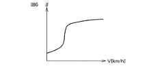
また、閾値変更部51は、車速Vと第2閾値βとの関係を記憶したマップに基づいて、車速Vに対応した第2閾値βを設定する。図6は、車速Vと第2閾値βとの関係を示すグラフである。第2閾値βは、車速の低速範囲では小さな値となり、車速が低速範囲を超えると急激に大きくなり、その後、緩やかに増加するように設定されている。これは、車両がほぼ停止している状態で行われる据え切り操作時においては、負荷が大きくなり、制御の追従性が遅くなる(転舵角偏差ΔδL,ΔδRの時間変化率の絶対値が小さくなる)ため、異常が発生してなくても、第2条件が満たされやすくなる。そこで、据え切り操作時において第2条件が満たされにくくなるように、車速が低速のときに第2閾値βを小さくしている。Further, the threshold
また、閾値変更部51は、車速Vと第3閾値γとの関係を記憶したマップに基づいて、車速Vに対応した第3閾値γを設定する。図7は、車速Vと第3閾値γとの関係を示すグラフである。第3閾値γは、車速の低速範囲では大きな値となり、車速が低速範囲を超えると急激に小さくなり、その後、緩やかに減少するように設定されている。この理由は、据え切り操作時に第2条件が満たされにくくなるように、車速が低速のときに第3閾値γを大きくしている。 Further, the threshold
前述の実施形態では、図4のステップS3に用いられる第2条件は、前記式(2)で示される条件である。しかし、第2条件は、次式(3)で示される条件であってもよい。
|dΔδL/dt|<β
or
|dΔδR/dt|<β …(3)
この場合には、異常判定部50は、「左転舵角偏差ΔδLの時間変化率の絶対値|dΔδL/dt|が第2閾値βよりも小さい」か、または「右転舵角偏差ΔδRの時間変化率の絶対値|dΔδR/dt|が第2閾値βよりも小さい」ときに、第2条件を満たしていると判別する。In the above-described embodiment, the second condition used in step S3 in FIG. 4 is a condition represented by the above equation (2). However, the second condition may be a condition represented by the following expression (3).
| DΔδL / dt | <β
or
| DΔδR / dt | <β (3)
In this case, the
前述の実施形態では、図4のステップS2で第1条件を満たしていないと判別された場合には(ステップS2:NO)、図4のステップS3に移行している。しかし、図4のステップS2で第1条件を満たしていないと判別された場合には(ステップS2:NO)、異常判定部50は、異常が発生していないと判定し、今演算周期での処理を終了するようにしてもよい。つまり、図4のステップS3を省略してもよい。 In the above-described embodiment, when it is determined in step S2 in FIG. 4 that the first condition is not satisfied (step S2: NO), the process proceeds to step S3 in FIG. However, if it is determined in step S2 of FIG. 4 that the first condition is not satisfied (step S2: NO), the
その他、特許請求の範囲に記載された事項の範囲で種々の設計変更を施すことが可能である。 In addition, various design changes can be made within the scope of matters described in the claims.
1…車両用操舵装置、2…ステアリングホイール、3L…左転舵輪、3R…右転舵輪、4L…左転舵モータ、4R…右転舵モータ、5L…左転舵機構、5R…右転舵機構、30…ECU、31…マイクロコンピュータ、40…転舵モータ制御部、42…目標転舵角設定部、43L,43R…転舵角偏差演算部、44L,44R…PI制御部、50…異常判定部、51…閾値変更部 DESCRIPTION OF
Claims (6)
Translated fromJapanese前記左転舵輪の転舵角の目標値である左目標転舵角および前記右転舵輪の転舵角の目標値である右目標転舵角を設定する目標転舵角設定手段と、
前記左転舵輪の転舵角である左転舵角を取得する左転舵角取得手段と、
前記右転舵輪の転舵角である右転舵角を取得する右転舵角取得手段と、
前記左転舵角と前記左目標転舵角との差である左転舵角偏差が小さくなるように前記左転舵モータを制御する左モータ制御手段と、
前記右転舵角と前記右目標転舵角との差である右転舵角偏差が小さくなるように前記右転舵モータを制御する右モータ制御手段と、
前記左転舵角偏差と前記右転舵角偏差との差の絶対値が第1閾値以上になったときに、異常が発生したと判定する判定手段とを含む、車両用操舵装置。Including a left steering mechanism and a right steering mechanism for individually steering left and right steered wheels, and a steering member operated for steering, the left steering mechanism and the right steering mechanism, A vehicle steering apparatus that is not mechanically coupled, the left steering mechanism is driven by a left steering motor, and the right steering mechanism is driven by a right steering motor,
Target turning angle setting means for setting a left target turning angle that is a target value of the turning angle of the left turning wheel and a right target turning angle that is a target value of the turning angle of the right turning wheel;
A left turning angle obtaining means for obtaining a left turning angle that is a turning angle of the left turning wheel;
A right turning angle obtaining means for obtaining a right turning angle that is a turning angle of the right turning wheel;
Left motor control means for controlling the left turning motor so that a left turning angle deviation which is a difference between the left turning angle and the left target turning angle is small;
A right motor control means for controlling the right turning motor so that a right turning angle deviation which is a difference between the right turning angle and the right target turning angle is small;
A vehicle steering apparatus comprising: determination means for determining that an abnormality has occurred when an absolute value of a difference between the left turning angle deviation and the right turning angle deviation is equal to or greater than a first threshold value.
前記車速取得手段によって取得された車速に応じて前記第1閾値を変更させる手段とをさらに含む、請求項1〜3のいずれか一項に記載の車両用操舵装置。Vehicle speed acquisition means for acquiring the vehicle speed;
The vehicle steering apparatus according to any one of claims 1 to 3, further comprising means for changing the first threshold value according to a vehicle speed acquired by the vehicle speed acquisition means.
前記車速取得手段によって取得された車速に応じて前記第1閾値を変更させる手段と、
前記車速取得手段によって取得された車速に応じて前記第2閾値を変更させる手段と、
をさらに含む、請求項2に記載の車両用操舵装置。Vehicle speed acquisition means for acquiring the vehicle speed;
Means for changing the first threshold according to the vehicle speed acquired by the vehicle speed acquisition means;
Means for changing the second threshold according to the vehicle speed acquired by the vehicle speed acquisition means;
The vehicle steering apparatus according to claim 2, further comprising:
前記車速取得手段によって取得された車速に応じて前記第1閾値を変更させる手段と、
前記車速取得手段によって取得された車速に応じて前記第3閾値を変更させる手段と、
前記車速取得手段によって取得された車速に応じて前記第4閾値を変更させる手段と、
をさらに含む、請求項3に記載の車両用操舵装置。Vehicle speed acquisition means for acquiring the vehicle speed;
Means for changing the first threshold according to the vehicle speed acquired by the vehicle speed acquisition means;
Means for changing the third threshold according to the vehicle speed acquired by the vehicle speed acquisition means;
Means for changing the fourth threshold according to the vehicle speed acquired by the vehicle speed acquisition means;
The vehicle steering apparatus according to claim 3, further comprising:
Priority Applications (4)
| Application Number | Priority Date | Filing Date | Title |
|---|---|---|---|
| JP2015233717AJP6579377B2 (en) | 2015-11-30 | 2015-11-30 | Vehicle steering system |
| US15/360,552US10011297B2 (en) | 2015-11-30 | 2016-11-23 | Vehicle steering device |
| CN201611062181.6ACN107054447B (en) | 2015-11-30 | 2016-11-25 | Vehicle steering system |
| EP16200747.0AEP3173315B1 (en) | 2015-11-30 | 2016-11-25 | Vehicle steering device |
Applications Claiming Priority (1)
| Application Number | Priority Date | Filing Date | Title |
|---|---|---|---|
| JP2015233717AJP6579377B2 (en) | 2015-11-30 | 2015-11-30 | Vehicle steering system |
Publications (2)
| Publication Number | Publication Date |
|---|---|
| JP2017100513A JP2017100513A (en) | 2017-06-08 |
| JP6579377B2true JP6579377B2 (en) | 2019-09-25 |
Family
ID=57396369
Family Applications (1)
| Application Number | Title | Priority Date | Filing Date |
|---|---|---|---|
| JP2015233717AActiveJP6579377B2 (en) | 2015-11-30 | 2015-11-30 | Vehicle steering system |
Country Status (4)
| Country | Link |
|---|---|
| US (1) | US10011297B2 (en) |
| EP (1) | EP3173315B1 (en) |
| JP (1) | JP6579377B2 (en) |
| CN (1) | CN107054447B (en) |
Families Citing this family (29)
| Publication number | Priority date | Publication date | Assignee | Title |
|---|---|---|---|---|
| EP2907730B1 (en) | 2014-01-29 | 2017-09-06 | Steering Solutions IP Holding Corporation | Hands on steering wheel detect |
| DE102016110791A1 (en) | 2015-06-15 | 2016-12-15 | Steering Solutions Ip Holding Corporation | Gesture control for a retractable steering wheel |
| US10112639B2 (en) | 2015-06-26 | 2018-10-30 | Steering Solutions Ip Holding Corporation | Vehicle steering arrangement and method of making same |
| JP6548023B2 (en)* | 2015-09-11 | 2019-07-24 | 株式会社ジェイテクト | Vehicle steering system |
| US10029725B2 (en)* | 2015-12-03 | 2018-07-24 | Steering Solutions Ip Holding Corporation | Torque feedback system for a steer-by-wire vehicle, vehicle having steering column, and method of providing feedback in vehicle |
| US10496102B2 (en) | 2016-04-11 | 2019-12-03 | Steering Solutions Ip Holding Corporation | Steering system for autonomous vehicle |
| DE102017108692B4 (en) | 2016-04-25 | 2024-09-26 | Steering Solutions Ip Holding Corporation | Control of an electric power steering system using system state predictions |
| US10160477B2 (en) | 2016-08-01 | 2018-12-25 | Steering Solutions Ip Holding Corporation | Electric power steering column assembly |
| US10384708B2 (en) | 2016-09-12 | 2019-08-20 | Steering Solutions Ip Holding Corporation | Intermediate shaft assembly for steer-by-wire steering system |
| US10399591B2 (en) | 2016-10-03 | 2019-09-03 | Steering Solutions Ip Holding Corporation | Steering compensation with grip sensing |
| JP6751511B2 (en)* | 2016-10-11 | 2020-09-09 | 株式会社ジェイテクト | Steering support device |
| US10239552B2 (en) | 2016-10-14 | 2019-03-26 | Steering Solutions Ip Holding Corporation | Rotation control assembly for a steering column |
| US10481602B2 (en) | 2016-10-17 | 2019-11-19 | Steering Solutions Ip Holding Corporation | Sensor fusion for autonomous driving transition control |
| US10310605B2 (en) | 2016-11-15 | 2019-06-04 | Steering Solutions Ip Holding Corporation | Haptic feedback for steering system controls |
| US10780915B2 (en) | 2016-12-07 | 2020-09-22 | Steering Solutions Ip Holding Corporation | Vehicle steering system having a user experience based automated driving to manual driving transition system and method |
| AU2018224858C1 (en) | 2017-02-25 | 2021-10-28 | Pride Mobility Products Corporation | Mobility vehicle |
| US10449927B2 (en) | 2017-04-13 | 2019-10-22 | Steering Solutions Ip Holding Corporation | Steering system having anti-theft capabilities |
| US10569784B2 (en) | 2017-09-28 | 2020-02-25 | Waymo Llc | Detecting and responding to propulsion and steering system errors for autonomous vehicles |
| JP6852668B2 (en)* | 2017-12-28 | 2021-03-31 | トヨタ自動車株式会社 | Steering by wire system |
| CN111902331B (en)* | 2018-03-26 | 2023-06-09 | 株式会社捷太格特 | Control device, steering device, control method, and recording medium |
| JP7035843B2 (en)* | 2018-06-26 | 2022-03-15 | トヨタ自動車株式会社 | Vehicle steering system |
| CN111098915A (en)* | 2018-10-26 | 2020-05-05 | 上汽通用汽车有限公司 | Steering mechanism stroke limit protection control method, computer readable storage medium and steering mechanism stroke limit protection control system |
| JP2020132008A (en)* | 2019-02-21 | 2020-08-31 | 株式会社ジェイテクト | Steering device |
| JP7234962B2 (en)* | 2020-02-11 | 2023-03-08 | トヨタ自動車株式会社 | Steering device and steering system provided with it |
| US11685427B2 (en) | 2021-04-12 | 2023-06-27 | Toyota Material Handling, Inc. | Electric actuator steering system for forklifts |
| JP7662423B2 (en)* | 2021-06-07 | 2025-04-15 | 株式会社ジェイテクト | Steering control device |
| JP7593282B2 (en)* | 2021-09-28 | 2024-12-03 | トヨタ自動車株式会社 | Vehicle, vehicle control method, and vehicle control interface box |
| CN114312985A (en)* | 2021-12-29 | 2022-04-12 | 深圳创维数字技术有限公司 | Vehicle control method, apparatus, device, and computer-readable storage medium |
| CA3209767A1 (en) | 2022-09-28 | 2024-03-28 | Toyota Material Handling, Inc. | Synchronized steering control systems for forklifts |
Family Cites Families (23)
| Publication number | Priority date | Publication date | Assignee | Title |
|---|---|---|---|---|
| JP3127688B2 (en)* | 1993-12-03 | 2001-01-29 | トヨタ自動車株式会社 | Feedback gain determination method |
| JP3650714B2 (en)* | 2000-02-08 | 2005-05-25 | 光洋精工株式会社 | Vehicle steering system |
| JP3770048B2 (en) | 2000-04-28 | 2006-04-26 | 日産自動車株式会社 | Steering device |
| JP2001322557A (en) | 2000-05-17 | 2001-11-20 | Toyota Motor Corp | Multi-wheel independent steering system for vehicles |
| DE10052343A1 (en)* | 2000-10-21 | 2002-07-11 | Bosch Gmbh Robert | Method for controlling a steerby wire steering system |
| US6561308B1 (en)* | 2001-11-30 | 2003-05-13 | Visteon Global Technologies, Inc. | Method of monitoring and deactivating a steer-by-wire system |
| US6799104B2 (en)* | 2003-01-13 | 2004-09-28 | Visteon Global Technologies, Inc. | System and method of controlling a vehicle steer-by-wire system applying robust control |
| US6728615B1 (en) | 2003-02-03 | 2004-04-27 | Visteon Global Technologies, Inc. | System and method of controlling vehicle steer-by-wire systems with adjustable steering feel |
| US7884715B2 (en)* | 2004-08-04 | 2011-02-08 | Nexteer (Beijing) Technology Co., Ltd. | Method and system for program execution integrity for communication-based angle sensor |
| JP4725132B2 (en)* | 2005-03-01 | 2011-07-13 | 日産自動車株式会社 | Steering control device |
| FR2883828B1 (en)* | 2005-04-01 | 2007-05-25 | Conception & Dev Michelin Sa | DIRECTION OF VEHICLE STEERING WITHOUT MECHANICAL CONNECTION BETWEEN STEERING WHEEL AND WHEELS |
| JP4722536B2 (en)* | 2005-04-19 | 2011-07-13 | 富士重工業株式会社 | Vehicle alignment management device |
| JP4539866B2 (en)* | 2006-01-13 | 2010-09-08 | トヨタ自動車株式会社 | Steering device |
| JP4876634B2 (en)* | 2006-03-01 | 2012-02-15 | 日産自動車株式会社 | Vehicle steering control device |
| JP4915504B2 (en)* | 2006-05-17 | 2012-04-11 | トヨタ自動車株式会社 | Vehicle steering device |
| US8200394B2 (en)* | 2006-12-04 | 2012-06-12 | Continental Teves Ag & Co. Ohg | System and method for adjustment of a steer angle of a wheel of a motor vehicle |
| JP2008174160A (en)* | 2007-01-19 | 2008-07-31 | Toyota Motor Corp | Vehicle steering device |
| EP2894079B1 (en)* | 2012-09-04 | 2016-12-07 | Nissan Motor Company, Limited | Stability control device |
| US9567003B2 (en)* | 2012-11-07 | 2017-02-14 | Nissan Motor Co., Ltd. | Steering control device |
| JP6142660B2 (en)* | 2013-05-13 | 2017-06-07 | 日産自動車株式会社 | Vehicle steering control device and vehicle steering control method |
| JP6167717B2 (en) | 2013-07-19 | 2017-07-26 | 日産自動車株式会社 | Suspension device |
| US20150090519A1 (en)* | 2013-09-30 | 2015-04-02 | Ford Global Technologies, Llc | Semi-decoupled steering system |
| JP2015091676A (en)* | 2013-11-08 | 2015-05-14 | 本田技研工業株式会社 | Vehicular steering apparatus |
- 2015
- 2015-11-30JPJP2015233717Apatent/JP6579377B2/enactiveActive
- 2016
- 2016-11-23USUS15/360,552patent/US10011297B2/enactiveActive
- 2016-11-25EPEP16200747.0Apatent/EP3173315B1/enactiveActive
- 2016-11-25CNCN201611062181.6Apatent/CN107054447B/enactiveActive
Also Published As
| Publication number | Publication date |
|---|---|
| CN107054447A (en) | 2017-08-18 |
| US10011297B2 (en) | 2018-07-03 |
| EP3173315A1 (en) | 2017-05-31 |
| US20170151978A1 (en) | 2017-06-01 |
| EP3173315B1 (en) | 2018-10-17 |
| JP2017100513A (en) | 2017-06-08 |
| CN107054447B (en) | 2021-03-02 |
Similar Documents
| Publication | Publication Date | Title |
|---|---|---|
| JP6579377B2 (en) | Vehicle steering system | |
| JP6548023B2 (en) | Vehicle steering system | |
| US10202145B2 (en) | Electric power steering system | |
| JP6260818B2 (en) | Electric power steering device | |
| JP2018062209A (en) | Steering support device | |
| US9415801B2 (en) | Power steering system | |
| CN107914765B (en) | Vehicle steering system | |
| US20180154937A1 (en) | Lane keep assist device | |
| JP6523720B2 (en) | Rear wheel steering control system | |
| JP5888546B2 (en) | Hydraulic power steering device | |
| US20160347358A1 (en) | Electric power steering device | |
| EP2821321A2 (en) | Electric power steering system | |
| WO2023127587A1 (en) | Steering control device | |
| JP6876251B2 (en) | Vehicle steering system | |
| JP2014141129A (en) | Electric power steering system | |
| JP6020881B2 (en) | Hydraulic power steering device | |
| JP6722381B2 (en) | Vehicle steering system | |
| JP6834414B2 (en) | Vehicle steering system | |
| JP2005028885A (en) | Steer-by-wire steering system |
Legal Events
| Date | Code | Title | Description |
|---|---|---|---|
| A621 | Written request for application examination | Free format text:JAPANESE INTERMEDIATE CODE: A621 Effective date:20181009 | |
| A977 | Report on retrieval | Free format text:JAPANESE INTERMEDIATE CODE: A971007 Effective date:20190723 | |
| TRDD | Decision of grant or rejection written | ||
| A01 | Written decision to grant a patent or to grant a registration (utility model) | Free format text:JAPANESE INTERMEDIATE CODE: A01 Effective date:20190801 | |
| A61 | First payment of annual fees (during grant procedure) | Free format text:JAPANESE INTERMEDIATE CODE: A61 Effective date:20190814 | |
| R150 | Certificate of patent or registration of utility model | Ref document number:6579377 Country of ref document:JP Free format text:JAPANESE INTERMEDIATE CODE: R150 |