JP6579301B2 - Cooker - Google Patents
CookerInfo
- Publication number
- JP6579301B2 JP6579301B2JP2014209417AJP2014209417AJP6579301B2JP 6579301 B2JP6579301 B2JP 6579301B2JP 2014209417 AJP2014209417 AJP 2014209417AJP 2014209417 AJP2014209417 AJP 2014209417AJP 6579301 B2JP6579301 B2JP 6579301B2
- Authority
- JP
- Japan
- Prior art keywords
- heating chamber
- wall surface
- camera
- air
- hole
- Prior art date
- Legal status (The legal status is an assumption and is not a legal conclusion. Google has not performed a legal analysis and makes no representation as to the accuracy of the status listed.)
- Active
Links
Images


Classifications
- H—ELECTRICITY
- H05—ELECTRIC TECHNIQUES NOT OTHERWISE PROVIDED FOR
- H05B—ELECTRIC HEATING; ELECTRIC LIGHT SOURCES NOT OTHERWISE PROVIDED FOR; CIRCUIT ARRANGEMENTS FOR ELECTRIC LIGHT SOURCES, IN GENERAL
- H05B6/00—Heating by electric, magnetic or electromagnetic fields
- H05B6/64—Heating using microwaves
- H05B6/66—Circuits
- H05B6/68—Circuits for monitoring or control
- H05B6/687—Circuits for monitoring or control for cooking
- A—HUMAN NECESSITIES
- A47—FURNITURE; DOMESTIC ARTICLES OR APPLIANCES; COFFEE MILLS; SPICE MILLS; SUCTION CLEANERS IN GENERAL
- A47J—KITCHEN EQUIPMENT; COFFEE MILLS; SPICE MILLS; APPARATUS FOR MAKING BEVERAGES
- A47J27/00—Cooking-vessels
- A47J27/002—Construction of cooking-vessels; Methods or processes of manufacturing specially adapted for cooking-vessels
- A—HUMAN NECESSITIES
- A47—FURNITURE; DOMESTIC ARTICLES OR APPLIANCES; COFFEE MILLS; SPICE MILLS; SUCTION CLEANERS IN GENERAL
- A47J—KITCHEN EQUIPMENT; COFFEE MILLS; SPICE MILLS; APPARATUS FOR MAKING BEVERAGES
- A47J27/00—Cooking-vessels
- A47J27/04—Cooking-vessels for cooking food in steam; Devices for extracting fruit juice by means of steam ; Vacuum cooking vessels
- A—HUMAN NECESSITIES
- A47—FURNITURE; DOMESTIC ARTICLES OR APPLIANCES; COFFEE MILLS; SPICE MILLS; SUCTION CLEANERS IN GENERAL
- A47J—KITCHEN EQUIPMENT; COFFEE MILLS; SPICE MILLS; APPARATUS FOR MAKING BEVERAGES
- A47J36/00—Parts, details or accessories of cooking-vessels
- F—MECHANICAL ENGINEERING; LIGHTING; HEATING; WEAPONS; BLASTING
- F24—HEATING; RANGES; VENTILATING
- F24C—DOMESTIC STOVES OR RANGES ; DETAILS OF DOMESTIC STOVES OR RANGES, OF GENERAL APPLICATION
- F24C15/00—Details
- F24C15/006—Arrangements for circulation of cooling air
- F—MECHANICAL ENGINEERING; LIGHTING; HEATING; WEAPONS; BLASTING
- F24—HEATING; RANGES; VENTILATING
- F24C—DOMESTIC STOVES OR RANGES ; DETAILS OF DOMESTIC STOVES OR RANGES, OF GENERAL APPLICATION
- F24C7/00—Stoves or ranges heated by electric energy
- F24C7/08—Arrangement or mounting of control or safety devices
- F24C7/082—Arrangement or mounting of control or safety devices on ranges, e.g. control panels, illumination
- F24C7/085—Arrangement or mounting of control or safety devices on ranges, e.g. control panels, illumination on baking ovens
- H—ELECTRICITY
- H05—ELECTRIC TECHNIQUES NOT OTHERWISE PROVIDED FOR
- H05B—ELECTRIC HEATING; ELECTRIC LIGHT SOURCES NOT OTHERWISE PROVIDED FOR; CIRCUIT ARRANGEMENTS FOR ELECTRIC LIGHT SOURCES, IN GENERAL
- H05B6/00—Heating by electric, magnetic or electromagnetic fields
- H05B6/64—Heating using microwaves
- H05B6/642—Cooling of the microwave components and related air circulation systems
- H—ELECTRICITY
- H05—ELECTRIC TECHNIQUES NOT OTHERWISE PROVIDED FOR
- H05B—ELECTRIC HEATING; ELECTRIC LIGHT SOURCES NOT OTHERWISE PROVIDED FOR; CIRCUIT ARRANGEMENTS FOR ELECTRIC LIGHT SOURCES, IN GENERAL
- H05B6/00—Heating by electric, magnetic or electromagnetic fields
- H05B6/64—Heating using microwaves
- H05B6/6447—Method of operation or details of the microwave heating apparatus related to the use of detectors or sensors
- H—ELECTRICITY
- H05—ELECTRIC TECHNIQUES NOT OTHERWISE PROVIDED FOR
- H05B—ELECTRIC HEATING; ELECTRIC LIGHT SOURCES NOT OTHERWISE PROVIDED FOR; CIRCUIT ARRANGEMENTS FOR ELECTRIC LIGHT SOURCES, IN GENERAL
- H05B6/00—Heating by electric, magnetic or electromagnetic fields
- H05B6/64—Heating using microwaves
- H05B6/647—Aspects related to microwave heating combined with other heating techniques
- H05B6/6473—Aspects related to microwave heating combined with other heating techniques combined with convection heating
- H05B6/6479—Aspects related to microwave heating combined with other heating techniques combined with convection heating using steam
- A—HUMAN NECESSITIES
- A47—FURNITURE; DOMESTIC ARTICLES OR APPLIANCES; COFFEE MILLS; SPICE MILLS; SUCTION CLEANERS IN GENERAL
- A47J—KITCHEN EQUIPMENT; COFFEE MILLS; SPICE MILLS; APPARATUS FOR MAKING BEVERAGES
- A47J27/00—Cooking-vessels
- A47J27/04—Cooking-vessels for cooking food in steam; Devices for extracting fruit juice by means of steam ; Vacuum cooking vessels
- A47J2027/043—Cooking-vessels for cooking food in steam; Devices for extracting fruit juice by means of steam ; Vacuum cooking vessels for cooking food in steam
- F—MECHANICAL ENGINEERING; LIGHTING; HEATING; WEAPONS; BLASTING
- F24—HEATING; RANGES; VENTILATING
- F24C—DOMESTIC STOVES OR RANGES ; DETAILS OF DOMESTIC STOVES OR RANGES, OF GENERAL APPLICATION
- F24C15/00—Details
- F24C15/32—Arrangements of ducts for hot gases, e.g. in or around baking ovens
- F24C15/322—Arrangements of ducts for hot gases, e.g. in or around baking ovens with forced circulation
- F24C15/327—Arrangements of ducts for hot gases, e.g. in or around baking ovens with forced circulation with air moisturising
Landscapes
- Engineering & Computer Science (AREA)
- Physics & Mathematics (AREA)
- Electromagnetism (AREA)
- Chemical & Material Sciences (AREA)
- Combustion & Propulsion (AREA)
- Mechanical Engineering (AREA)
- General Engineering & Computer Science (AREA)
- Food Science & Technology (AREA)
- Manufacturing & Machinery (AREA)
- Electric Ovens (AREA)
Description
Translated fromJapanese本発明は、食品等を加熱調理するための加熱調理器に関する。 The present invention relates to a cooking device for cooking food and the like.
加熱調理器において、加熱室内の食品の状態を確認するために各種の構成部材を備えたものがある(例えば、特許文献1参照)。特許文献1の加熱調理器では、食品の温度を検知する赤外線センサが設けられている。食品からの赤外線を、赤外線通過口を通して赤外線センサに受光することで、食品温度を検知して加熱調理を行っている。 Some cooking devices include various components for confirming the state of food in the heating chamber (see, for example, Patent Document 1). In the heating cooker of
このような構成において、特許文献1ではさらに、加熱室の壁面に形成された赤外線通過口を通して加熱室内に送風するための第1風路と、赤外線センサと赤外線通過口との間にて、第1風路から概ね垂直に分岐する第2風路とを設けている。このような2つの風路を設けることで、加熱室内の食品カスなどの飛散物が開口を通って上昇してセンサなどを汚すことを抑制するようにしている。さらに、第1風路だけでなく第2風路も設けて風路を分散させることにより、加熱室内の温度が過剰に低下することを抑制するようにしている。 In such a configuration, in
ここで、調理を行うための加熱室内においては、温度や湿度等の条件を含めて、環境が大きく変化する。昨今の加熱調理器では、例えば、蒸気機能などの機能付加の高まりもあり、このような加熱室内の環境変化はより顕著な傾向にある。 Here, in the heating chamber for cooking, the environment changes greatly including conditions such as temperature and humidity. In recent cooking devices, for example, there is an increase in the addition of functions such as a steam function, and such environmental changes in the heating chamber tend to be more prominent.
一方で、加熱調理器の付加的な機能として、加熱室内の食品の状態を確認するための撮像部を備えた加熱調理器なども開発されている。このような撮像部を備える加熱調理器において、加熱室内の環境変化に応じた工夫、例えば、撮像部の信頼性を低下させずに向上させる工夫や、撮像部による視認性を向上させる工夫などが求められる。 On the other hand, as an additional function of the cooking device, a cooking device including an imaging unit for confirming the state of food in the heating chamber has been developed. In a heating cooker equipped with such an imaging unit, there are ingenuity according to environmental changes in the heating chamber, for example, an improvement to improve the reliability of the imaging unit, an improvement to improve the visibility by the imaging unit, etc. Desired.
従って、本発明の目的は、撮像部を備える構成において、撮像部の信頼性を向上させるとともに、視認性を向上させることができる加熱調理器を提供することにある。 Accordingly, an object of the present invention is to provide a cooking device capable of improving the reliability of the imaging unit and improving the visibility in the configuration including the imaging unit.
上記目的を達成するために、本発明は以下のように構成する。 In order to achieve the above object, the present invention is configured as follows.
本発明の一態様によれば、食品を収納する加熱室と、
加熱室の側壁面に形成された貫通孔と、
貫通孔を通じて加熱室内を撮像する撮像部と、
加熱室の外側にて送風を行う送風部と、
送風部による風をガイドする送風ガイドと、を備え、
送風ガイドは、送風部からの風が撮像部と貫通孔との間の空間を横切るエアカーテンを形成するように配置される、加熱調理器を提供する。According to one aspect of the present invention, a heating chamber that houses food,
A through hole formed in the side wall surface of the heating chamber;
An imaging unit for imaging the heating chamber through the through hole;
A blower that blows air outside the heating chamber;
A blowing guide for guiding the wind by the blowing section,
A ventilation guide provides the heating cooker arrange | positioned so that the wind from a ventilation part may form the air curtain which crosses the space between an imaging part and a through-hole.
本発明の加熱調理器は、撮像部の信頼性および視認性を向上させることができる。 The heating cooker of this invention can improve the reliability and visibility of an imaging part.
第1の発明は、食品を収納する加熱室と、加熱室の側壁面に形成された貫通孔と、貫通孔を通じて加熱室内を撮像する撮像部と、加熱室の外側にて送風を行う送風部と、送風部による風をガイドする送風ガイドと、を備え、送風ガイドは、送風部からの風が撮像部と貫通孔との間の空間を横切るエアカーテンを形成するように配置される、加熱調理器である。これにより、撮像部と貫通孔との間にはエアカーテンが形成されているため、加熱室内の熱風や蒸気などを含む空気が貫通孔からカメラに到達することを防ぐことができる。これにより、撮像部を備えた構成において、加熱室内の空気が撮像部に到達して撮像部に与える悪影響を抑制することができ、撮像部の信頼性および視認性を向上させることができる。 1st invention is the heating chamber which accommodates a foodstuff, the through-hole formed in the side wall surface of a heating chamber, the imaging part which images a heating chamber through a through-hole, and the ventilation part which ventilates on the outer side of a heating chamber And a blowing guide that guides the wind by the blowing unit, and the blowing guide is arranged so that the wind from the blowing unit forms an air curtain that crosses the space between the imaging unit and the through hole. It is a cooker. Thereby, since an air curtain is formed between the imaging unit and the through hole, it is possible to prevent air including hot air or steam in the heating chamber from reaching the camera from the through hole. Thereby, in the structure provided with the imaging part, the bad influence which the air in a heating chamber reaches | attains an imaging part and has on an imaging part can be suppressed, and the reliability and visibility of an imaging part can be improved.
第2の発明は、第1の発明において、貫通孔の内周から加熱室の外側に向って延出した延出部をさらに備える。これにより、送風部からの風が加熱室内に入ることを抑制することができる。 According to a second invention, in the first invention, an extension portion extending from the inner periphery of the through hole toward the outside of the heating chamber is further provided. Thereby, it can suppress that the wind from a ventilation part enters into a heating chamber.
第3の発明は、第1又は第2の発明において、延出部の外側における加熱室の壁面との境界は、曲線状に湾曲しながら立ち上がるように形成される。これにより、延出部がこのような形状を呈することにより、加熱室の壁面から直角に立ち上がる場合よりも、送風部からの風と対向する領域において、気流の流れを整えることができる。これにより、送風部による風が加熱室内へ入ることをさらに抑制することができる。 According to a third invention, in the first or second invention, the boundary with the wall surface of the heating chamber outside the extension portion is formed to rise while curving in a curved shape. Thereby, when the extension part exhibits such a shape, the flow of the airflow can be adjusted in a region facing the wind from the air blowing part, as compared with the case where the extension part rises at a right angle from the wall surface of the heating chamber. Thereby, it can further suppress that the wind by a ventilation part enters into a heating chamber.
第4の発明は、第1から第3のいずれか1つの発明において、送風部は、撮像部よりも下方に配置され、送風ガイドは、送風部からの風を上方に向けてガイドするよう配置される。これにより、送風部からの風を上方に向けてガイドすることにより、温度が熱くなりやすい加熱調理器内の上方を、送風部からの風を利用して効率的に冷却することができる。 According to a fourth aspect of the present invention, in any one of the first to third aspects, the air blowing unit is disposed below the imaging unit, and the air blowing guide is disposed so as to guide the wind from the air blowing unit upward. Is done. Thereby, by guiding the wind from the blower section upward, the upper portion in the heating cooker where the temperature tends to be hot can be efficiently cooled using the wind from the blower section.
第5の発明は、第1から第4のいずれか1つの発明において、加熱室内にマイクロ波を供給するマイクロ波供給部を備える。 According to a fifth aspect of the present invention, in any one of the first to fourth aspects, a microwave supply unit that supplies a microwave to the heating chamber is provided.
第6の発明は、第1から第5のいずれか1つの発明において、加熱室内に蒸気を供給する蒸気供給部を備える。これにより、加熱室内の蒸気の充満量が多くなりやすいのに対して、エアカーテンを形成することによって、蒸気が貫通孔を通じて撮像部に到達することを抑制することができる。これにより、撮像部の信頼性および撮像部による視認性を向上させることができる。 According to a sixth invention, in any one of the first to fifth inventions, a sixth aspect includes a steam supply unit that supplies steam into the heating chamber. Thereby, while the filling amount of the vapor | steam in a heating chamber tends to increase, it can suppress that a vapor | steam reaches | attains an imaging part through a through-hole by forming an air curtain. Thereby, the reliability of an imaging part and the visibility by an imaging part can be improved.
第7の発明は、第6の発明において、加熱室内の蒸気を加熱室外へ排出するように、加熱室の壁面に形成された排出孔をさらに備える。これにより、蒸気供給部を備えた構成において、排出孔から蒸気を排出することができるため、撮像部用の貫通孔を通過しようとする蒸気の量を低減することができる。よって、撮像部の信頼性を向上させることができる。 A seventh invention further includes a discharge hole formed in the wall surface of the heating chamber so as to discharge the steam in the heating chamber to the outside of the heating chamber in the sixth invention. Thereby, in the configuration provided with the steam supply unit, the steam can be discharged from the discharge hole, so that the amount of the steam that tries to pass through the through hole for the imaging unit can be reduced. Therefore, the reliability of the imaging unit can be improved.
以下、本発明の加熱調理器に係る実施の形態1について、添付の図面を参照しながら説明する。なお、本発明の加熱調理器は、以下の実施の形態1に記載した加熱調理器の構成に限定されるものではない。 Hereinafter,
(実施の形態1)
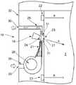
図1は、本発明の実施の形態1にかかる加熱調理器1の正面図を示す。図2は、実施の形態1にかかる加熱調理器1の側面断面図を示す。実施の形態1の加熱調理器1は、加熱室2内にて食品等(図示せず)を加熱調理するための装置である。(Embodiment 1)
FIG. 1: shows the front view of the
図1、2に示すように、加熱調理器1は、内部に加熱室2を形成する本体3と、ドア4とを備える。 As shown in FIGS. 1 and 2, the
本体3は、内部に加熱室2を形成するとともに加熱調理器1の外側の筐体として構成されている。図1に示すように、本体3の前面上方には、表示部5と、操作部6とが設けられている。表示部5は、加熱調理器1の運転状態等の表示を行うための部分である。実施の形態1における表示部5は、液晶画面で構成されている。操作部6は、ユーザが加熱調理器1を操作するための部分である。実施の形態1における操作部6は、ユーザによって操作可能な複数のボタンで構成される。ユーザが操作部6のボタンを押すことで、加熱調理器1の各種運転を制御することができる。操作部6で選択された加熱調理器1の運転等の内容は、表示部5に表示される。 The main body 3 is configured as a housing outside the
実施の形態1において、本体3の加熱室2を形成する壁面は例えば、ホウロウ鋼板、ステンレス鋼板、塗装鋼板などの材料により形成されている。 In the first embodiment, the wall surface forming the
ドア4は、本体3に開閉可能に取り付けられたドアである。実施の形態1におけるドア4は、本体3の前面下方にて、前後方向に回転可能に取り付けられるとともに、ユーザが把持可能なハンドル(図示せず)を有する。ユーザがドア4のハンドルを操作することで、ドア4を開閉することができる。図1では、ドア4が閉じられた状態(加熱室2へアクセスできない状態)が示されており、図2では、ドア4が開かれた状態(加熱室2へアクセスできる状態)が示される。 The door 4 is a door attached to the main body 3 so as to be opened and closed. The door 4 in the first embodiment is attached to the lower side of the front surface of the main body 3 so as to be rotatable in the front-rear direction and has a handle (not shown) that can be gripped by the user. The user can open and close the door 4 by operating the handle of the door 4. FIG. 1 shows a state where the door 4 is closed (a state where the
図2に示すように、加熱調理器1はさらに、本体3の内部において、蒸気供給部7と、ヒータ部8と、マイクロ波供給部9とを備える。 As shown in FIG. 2, the
蒸気供給部7は、食品等を加熱調理するための蒸気を、加熱室2へ供給するための機構である。実施の形態1における蒸気供給部7は、加熱室2の上壁面2aの上方に配置されており、水タンク10と、蒸気用ヒータ11とを備えている。 The
水タンク10は、蒸気生成用の水を貯めるタンクである。蒸気用ヒータ11は、水タンク10の水を加熱するためのヒータである。図2に示すように、水タンク10に隣接して蒸気用ヒータ11が設けられている。蒸気用ヒータ11によって水タンク10の水が所定温度以上まで加熱されると、その水は蒸発し、蒸気となる。この蒸気は、図2に示される加熱室2の上壁面2aに設けられた蒸気供給孔12を通じて、加熱室2へ供給される。なお、水タンク10の水はユーザによって補充可能に構成されている。 The
ヒータ部8は、対流熱又は輻射熱により加熱室2を加熱するための機構である。実施の形態1におけるヒータ部8は、加熱室2の背壁面2bの後方(背面側)に配置されており、シーズヒーター等のコンベクションヒータ13と、遠心ファン14とを備える。加熱室2の背壁面2bには、加熱室2と、ヒータ部8が配置される背面側の空間とを連通するための複数の孔(図示せず)が設けられている。このような構成において、コンベクションヒータ13により加熱された空気を、遠心ファン14によって加熱室2内へ向けて吹き出すことで、加熱室2および加熱室2内に配置された食品等を対流熱又は輻射熱により加熱する。 The heater unit 8 is a mechanism for heating the
マイクロ波供給部9は、加熱室2内の食品等を加熱するためのマイクロ波を加熱室2へ供給するための機構である。実施の形態1におけるマイクロ波供給部9は、加熱室2の底壁面2cの下方に設けられるとともに、マグネトロン15と、導波管16aと、アンテナ16bとを備え、マイクロ波を透過させる結晶化ガラス等のカバー2fで覆われている。加熱室2の底壁面2cは、カバー2fの上面により構成されている。マグネトロン15は、マイクロ波を発生させるマイクロ波発生部の一例である。マグネトロン15が発生させたマイクロ波は、アンテナ16bに向けられる。アンテナ16bは、マグネトロン15からのマイクロ波を加熱室2内に拡散するためのアンテナである。このような構成において、マグネトロン15が発生させたマイクロ波は、アンテナ16bによって拡散されて、カバー2fを通過して加熱室2内に供給される。 The microwave supply unit 9 is a mechanism for supplying a microwave for heating the food in the
実施の形態1における加熱調理器1はさらに、インバータ17を備える。インバータ17は、マグネトロン15を駆動するための回路機構である。 The
実施の形態1における加熱調理器1はさらに、制御部36(図1)を備える。制御部36は、加熱調理器1が備える各種構成要素の駆動に関して、全体的な制御を行う。制御部36は例えば、操作部6で入力された内容に基づき、予め組み込まれたプログラムに応じて、所定の調理コースを実施するようにインバータ17などの駆動を制御する。 The
上述した構成を備えることにより、実施の形態1における加熱調理器1は、加熱室2内の食品等に対して、蒸気供給部7による蒸気加熱と、ヒータ部8による対流・輻射加熱と、マイクロ波供給部9によるマイクロ加熱とを実施することができる。これらの加熱方法は、単独又は適宜組み合わせて実施することができる。 By providing the above-described configuration, the
次に、加熱調理器1に設けられた撮像ユニット18について、図3、4を用いて説明する。図3は、実施の形態1にかかる加熱調理器1の正面断面図であり、図4は、加熱調理器1の正面拡大断面図を示す。 Next, the
撮像ユニット18は、加熱室2内を撮像して、加熱室2内の画像を取得するためのユニットである。実施の形態1における撮像ユニット18は、図3に示すように、加熱室2の一方側の側壁面2d(図3では左側)に隣接する位置に設けられている。撮像ユニット18により撮像された加熱室2内の画像は、例えば、ユーザが確認できるように表示部5に表示される。 The
図4には、加熱調理器1の側壁面2dの周辺部を、図3に示される撮像ユニット18を中心に拡大した図が示されている。図4に示すように、実施の形態1における撮像ユニット18は、カメラ19と、送風ファン20と、送風ガイド21と、照明部22、23とを備える。 FIG. 4 shows an enlarged view of the peripheral part of the
カメラ19は、加熱室2内を撮像する撮像部の一例である。実施の形態1におけるカメラ19は、レンズ24と、撮像センサ(図示せず)とを備える。カメラ19の先端に設けられたレンズ24を通じて取得した光を、撮像センサで検知することにより加熱室2内を撮像して、加熱室2内の画像を取得する。カメラ19のレンズ24を通じた撮像が可能なように、加熱室2の側壁面2dには、貫通孔25が形成される。カメラ19は、図4に示すように、加熱室2の側壁面2dよりも加熱室2から離れる方向にずれた位置にて本体3に固定されている。カメラ19の先端に位置するレンズ24は、貫通孔25を通じて加熱室2内の食品等を視野内に収めるように、加熱室2内に向けて配置されている。図4に示される例では、概ね加熱室2の中央に向くように配置されている。図4において、カメラ19が撮像する方向を撮像方向Aとする。 The
カメラ19が加熱室2を向いている撮像方向Aが、水平に延びる加熱室2の底壁面2c(図3)に対して成す角度(すなわち、水平方向に対して成す角度)をカメラ19の撮像角度とすると、図4に示す例では、25°下方に設定されている。なお、この角度は、カメラの画角に応じて0°―50°の下方であればよい。 The imaging direction A in which the
送風ファン20は、カメラ19の下方において本体3に固定されたファンであり、上方に向けて風を吹き出すように配置される。 The
送風ガイド21は、送風ファン20が吹き出す風をガイドするための部材である。実施の形態1における送風ガイド21は、送風ファン20の上側に取り付けられるとともに、送風ファン20が吹き出す風を、カメラ19のレンズ24と貫通孔25の間の空間27を通過するように上方へガイドする。 The
このように、送風ファン20が吹き出す風を送風ガイド21によってガイドして、カメラ19のレンズ24と貫通孔25の間の空間27を通過させることにより、カメラ19に対するエアカーテンを形成している。このエアカーテンの詳細については後述する。 In this manner, the air blown by the
照明部22、23は、加熱室2内に光を照射して、加熱室2内の照明を行うための部材である。実施の形態1では、照明部22、23は、カメラ19の上方と下方のそれぞれに1つずつ設けられている。実施の形態1における照明部22、23は、ともにLEDで構成されている。 The
図4に示すように、照明部22、23は、加熱室2の側壁面2dに設けられている。照明部22、23が照射する光は、側壁面2dに対向する側壁面2e(図3)に向かって、略平行光を照射する。平行光とは平行に進む光のことであり、本明細書における「略平行光」とは、レンズ付きのLEDのように点光源をレンズで収束させた光を意味する。図4において、照明部22、23が光を照射する方向を照射方向Bとする。実施の形態1では、照明部22、23は、ともに水平方向に進む略平行光を照射する。 As shown in FIG. 4, the
照明部22、23の照射方向Bが、水平に延びる加熱室2の底壁面2c(図3)に対して成す角度(すなわち、水平方向に対して成す角度)を照明部22、23の照射角度とすると、図4に示す例では、0°に設定されている。 The angle formed by the irradiation direction B of the
前述したカメラ19の撮像方向Aと、照明部22、23の照射方向Bを、例えば、0°―25°の範囲内の差となるように設定している。言い換えれば、照明部22、23の照射角度と、カメラ19の撮像角度を、例えば、0°―25°の範囲内の差となるように設定している。 The above-described imaging direction A of the
ここで、照明部22、23が照射する光の波長は、380nm−780nmの範囲内とすることが好ましい。このような範囲であれば、可視光範囲の波長に該当するため、照明部22、23の光を、加熱調理器1のカメラ19およびユーザが認識することができる。さらに、照明部22、23が照射する光の最大発光強度を示す波長は、550nm−780nmの範囲内とすることより好ましい。このような範囲であれば、いわゆる長波長の範囲であるため、照明部22、23が照射する光は赤色系となる。実施の形態1では、例えば、580nmとして、可視光範囲かつ長波長の範囲となるように設定されている。このようにして、照明部22、23による赤色系の照明を、カメラ19およびユーザが加熱室2内にて明瞭に認識することができるようにしている。 Here, it is preferable that the wavelength of the light irradiated by the illuminating
また実施の形態1では、加熱室2の壁面を構成する材料を例えばホウロウ鋼板とすることで、照明部22、23が照射する光の最大発光強度を示す波長を580nmとした場合、当該波長に対する反射率を18%程度としている。このように、照明部22、23が照射する光の波長に対して、加熱室2の内壁の反射率が20%以内となるように、光の波長や内壁の材料を選択している。 Moreover, in
図4に示すように、上述した撮像ユニット18の各構成要素の近傍においては、第1の風路26と、第2の風路(後述)と、第3の風路28とが設けられている。 As shown in FIG. 4, a
第1の風路26は、加熱調理器1の外部から送風ファン20へ空気を通すための風路である。第1の風路26は、本体3の外側側壁面32に設けられた吸気口29と、送風ファン20の上流側開口端部とに連通されている。第1の風路26の風は、送風ファン20に送られる。送風ファン20は、第1の風路26からの風を吹き出すとともに、送風ガイド21がその風をガイドする。送風ガイド21はその風を、カメラ19のレンズ24と貫通孔25の間の空間27を通過する方向へガイドする。すなわち、送風ファン20と送風ガイド21によって、第2の風路を形成している。第3の風路28は、カメラ19のレンズ24と貫通孔25の間の空間27を通過した空気を加熱調理器1の外部へ排気するための風路である。第3の風路28は、カメラ19のレンズ24および貫通孔25の間の空間27と、加熱調理器1の外側側壁面32に設けられた排気口30との間に連通されている。 The
このような構成によれば、吸気口29から吸気される空気を送風ファン20が吹き出すとともに、その風を送風ガイド21(および第2の風路27)によってガイドしながら、カメラ19のレンズ24と貫通孔25の間の空間27を通過させる。これにより、加熱室2内の空間に対するカメラ19用のエアカーテンが形成される。エアカーテンを形成した風はその後、排気口30を介して外部に排気される。 According to such a configuration, while the
貫通孔25を形成している加熱室2の側壁面2dには、図4に示すように、延出部31が設けられている。延出部31は、貫通孔25の内周から加熱室2の外側(図4の紙面左方向)に向かって延出した部分である。実施の形態1では、延出部31は、加熱室2の側壁面2dから垂直に立ち上がる(すなわち水平方向に延びる)ように形成されている。 As shown in FIG. 4, an
次に、上述した撮像ユニット18やその周辺の構成部材による作用・効果について説明する。 Next, functions and effects of the above-described
加熱室2内においては、特に加熱調理中には、食品やその周囲の空気も含めて、温度が高くなっている(例えば、200℃)。温度が高いだけでなく、蒸気供給部7から供給される蒸気や、ヒータ部8およびマイクロ波供給部9によって食品が加熱されることで生じる蒸気が充満していることも多い。このような環境下において、実施の形態1の加熱調理器1は、加熱室2の側壁面2dにカメラ19用の貫通孔25を設けた構造であるため、加熱室2内の熱風や蒸気を含む空気が、貫通孔25を通じて加熱室2の外に出る可能性がある。このような空気が加熱室2の外に出た場合には、貫通孔25の近傍にあるカメラ19(特にレンズ24)に到達する場合がある。 In the
そこで、実施の形態1の加熱調理器1では、撮像ユニット18として送風ファン20と送風ガイド21を備えるとともに、送風ガイド21は、送風ファン20からの風がカメラ19と貫通孔25との間の空間を横切るエアカーテンを形成するようにしている。これにより、加熱室2内の空気がカメラ19(特にレンズ24)に到達することを抑制することができる。すなわち、熱風や蒸気などによるカメラ19への悪影響(カメラ19への熱的ダメージ、レンズ24の曇りなど)が低減されるため、カメラ19の信頼性を向上させることができる。また、エアカーテンを形成することにより、送風ガイド21によってガイドされる風が、貫通孔25を通じて加熱室2内へ移動する誘引作用も低減することもできる。また、カメラ19の撮像角度が上向きの場合には、カメラ19のレンズ24に衝突するエアカーテンの風は、第3の風路28側へ抜けやすくなるのに対して、実施の形態1では、カメラ19の撮像角度を下向きに設定している。このような場合、カメラ19のレンズ24に衝突したエアカーテンの風は、第3の風路28ではなく、貫通孔25を抜けて加熱室2内へ放出されやすい。このように、カメラ19の撮像角度を下向きに設定することで、貫通孔25から熱気や蒸気が拡散することを防止することができる。 Therefore, the
さらに、実施の形態1では、加熱室2内に蒸気を供給する蒸気供給部7を設けているため、加熱室2内の蒸気の充満量が多くなりやすいのに対して、前述したエアカーテンを形成することによって、蒸気が貫通孔25を通じてカメラ19に到達することを抑制することができる。これにより、カメラ19の信頼性およびカメラ19による視認性を向上させることができる。 Furthermore, in
なお、実施の形態1では、送風ガイド21は、レンズ24の表面に風を沿わせる/当てるようにガイドするとともに、エアカーテンを形成する方向(図4における紙面上方向)にのみ風をガイドしている。言い換えれば、送風ガイド21は、レンズ24と貫通孔25を横切る一方向の気流を形成するようガイドしている。これにより、より確実なエアカーテンの形成を行うとともに、加熱室2内の空間に対する遮断機能を向上高めている。 In the first embodiment, the
また、このようなエアカーテンを形成した場合、エアカーテンを形成する風が貫通孔25を通じて加熱室2内へ誘引されることをより確実に防ぐことが好ましい。そこで実施の形態1では、図4に示すように、貫通孔25から外側に延出した延出部31を設けている。延出部31を設けることにより、延出部31を設けずに貫通孔25のみを設けた場合よりも、エアカーテンを形成する風が貫通孔25を通じて加熱室2内へ移動することをさらに抑制することができる。これにより、より確実にエアカーテンを形成することができ、カメラ19の信頼性を向上させることができる。 Further, when such an air curtain is formed, it is preferable to more reliably prevent the wind forming the air curtain from being drawn into the
また、実施の形態1では、マイクロ波を供給するマイクロ波供給部9を設けているため、加熱室2内のマイクロ波が、貫通孔25を通じて外部へ漏れないようにすることが好ましい。これに対して、前述した延出部31を設けていることで、加熱室2内のマイクロ波が貫通孔25から外部へ漏れることを抑制することもできる。これにより、マイクロ波の影響を受けやすいカメラ19にマイクロ波が到達することを防止し、カメラ19によって安定した画像を得ることができる。 In the first embodiment, since the microwave supply unit 9 that supplies the microwave is provided, it is preferable that the microwave in the
また、実施の形態1では、送風ガイド21は、上方に向けて風をガイドするように設けられている。一般的な加熱調理器1では、加熱室2を形成する本体3において、下方よりも上方の部分の方が、温度が高くなりやすい傾向にある。これに対して、実施の形態1のように、送風ガイド21を上方に向けて風をガイドするように配置すれば、下方に向けて風をガイドする場合に比べて、加熱調理器1の本体3の中でも相対的に温度の高い箇所を冷却することができる。これにより、本体3の温度が過剰に高くなることを抑制することができる。 In the first embodiment, the
上述したエアカーテンの形成に加えて、実施の形態1では、照明部22、23を用いて加熱室2内を照明するようにしている。これより、カメラ19による視認性を向上させることができる。 In addition to the formation of the air curtain described above, in the first embodiment, the interior of the
実施の形態1では特に、照明部22、23を、カメラ19が配置されている側の側壁面2dと同じ側、すなわち、貫通孔25が形成された加熱室2の側壁面2d側に配置している。このような配置によれば、照明部22、23は、カメラ19と対向しない位置にあるため、カメラ19との位置関係において、逆光の関係にならない。これにより、カメラ19による視認性を向上させることができる。なお、逆光の関係とならないようにする場合には、照明部22、23を加熱室2の側壁面2d以外にも、上壁面2aや底壁2cに配置してもよい。すなわち、照明部22、23を、カメラ19が配置される壁面(側壁面2d)に対向する壁面(側壁面2e)以外に配置すれば、逆光の関係にならないようにすることができる。 In the first embodiment, in particular, the
また、照明部22、23をカメラ19と対向しないだけでなく、カメラ19が設けられている加熱室2の側壁面2dと同じ側に配置することで、カメラ19との位置関係において、順光の関係となる。加熱室2内の蒸気が結露した霧は粒径が1−100μmであるため、ミー散乱から幾何学散乱となり、前方散乱が大きい(光の進行方向に向けての散乱)。このため、照明部22、23をカメラ19と同じ側壁面2d側に設けることで、順光の関係として、当該前方散乱による影響を低減することができる。これにより、カメラ19による視認性をさらに向上させることができる。 Further, not only the
また実施の形態1では、図4に示すように、照明部22、23の照射角度とカメラ19の撮像角度との差を所定の範囲内(例えば、0°―25°の範囲)に設定しているため、より精度の良い順光の関係とすることができる。これにより、カメラ19による視認性をさらに向上させることができる。 In the first embodiment, as shown in FIG. 4, the difference between the illumination angle of the
また、実施の形態1における照明部22、23が照射する光の波長は、最大発光強度を示す波長を550nm〜780nmに設定している。このような範囲であれば、可視光範囲の波長である380−780nmの範囲内に該当するため、加熱室2内をより明瞭に照らし、カメラ19による視認性を向上させることができる。また、550nm〜780nmは、長波長の範囲でもあるため、照射部22、23から照射される光の色は赤色系となる。これより、最大発光強度を示す波長を低波長(例えば、380nm〜550nm)に設定した場合に照射される青色系の光に比べて、加熱室2内を明瞭に照らすことができ、カメラ19による視認性をさらに向上させることができる。なお、白色LED等で、複数の発光スペクトルを組み合せた照明では、発光エネルギーが最大のスペクトルを580−780nmとすることで同様の効果を得ることができる。実施の形態1ではさらに、照明部22、23は、波長が380−780nmという可視光範囲において、水平方向に向かう略平行光を照射する。このように、指向特性θ1/2が60°以下のLED等で略平行光とすることで、散乱を防止し、カメラ19による視認性を向上させることができる。 Moreover, the wavelength of the light irradiated by the illuminating
照明部22、23が照射する光は、加熱室2の壁面に到達する。実施の形態1では特に、照明部22、23が照射する光は、水平方向沿いの略平行光であるため、その大部分は側壁面2dに対向する側壁面2e(図3)に到達する。ここで、実施の形態1では、加熱室2内の壁面の表面は、照明部22、23が照射する光の波長(例えば、580nm)における反射率が20%以下の材料(具体的には、ホウロウ鋼板など)により形成されている。このような反射率の設定により、照明部22、23によって照射される光が加熱室2内の壁面(特に、側壁面2dに対向する側壁面2e)で反射することを抑制することができるため、カメラ19による視認性をさらに向上させることができる。 The light irradiated by the
上述した構成において、蒸気を供給するための蒸気供給孔12は、加熱室2の上壁面2aに設けられている。すなわち、蒸気供給孔12は、撮像部であるカメラ19が配置される側壁面2dと対向しない加熱室2内の壁面に配置されている。このような蒸気供給孔12の配置により、蒸気供給孔12から供給される蒸気がカメラ19に直接向かう量を減らすことができるため、蒸気によるカメラ19への視認性の悪影響を低減することができる。 In the configuration described above, the
上述したように、実施の形態1の加熱調理器1は、食品を収納する加熱室2と、加熱室2の側壁面2dに形成された貫通孔25と、貫通孔25を通じて加熱室2内を撮像するカメラ19(撮像部)と、加熱室2の外側にて送風を行う送風ファン20(送風部)と、送風ファン20による風をガイドする送風ガイド21と、を備える。また、送風ガイド21は、送風ファン20からの風がカメラ19と貫通孔25との間の空間を横切るエアカーテンを形成するように配置される。このような構成によれば、カメラ19と貫通孔25との間にはエアカーテンが形成されているため、加熱室2内の熱風や蒸気などを含む空気が貫通孔25からカメラ19に到達することを防ぐことができる。これにより、カメラ19を備えた構成において、加熱室2内の空気がカメラ19に到達してカメラ19に与える悪影響を抑制することができ、カメラ19の信頼性および視認性を向上させることができる。 As described above, the
また、実施の形態1の加熱調理器1は、食品を収納する加熱室2と、加熱室2の側壁面2dに形成された貫通孔25と、貫通孔25を介して加熱室2内を撮影するカメラ19(撮像部)と、貫通孔25が形成された側壁面2d側に設けられ、加熱室2内に光を照射する照明部22、23(第1の照明部)と、を備える。このように、カメラ19を備えた構成において、加熱室2内を照らす照明部22、23をさらに備えることで、加熱室2内の蒸気によって加熱室2内の透過度が低下している場合でも、カメラ19による視認性を向上させることができる。また、照明部22、23は、貫通孔25が形成された側壁面2d側に設けられているため、カメラ19と第1の照明部が逆光の関係にならず、カメラ19による視認性をさらに向上させることができる。 The
以上、上述の実施の形態1を挙げて本発明を説明したが、本発明は上述の実施の形態1に限定されない。例えば、実施の形態1では、蒸気供給部7を設けた構成例を示したが、ヒータやマイクロ波による加熱によって蒸気を発生させる調理でも同様の効果があるのは言うまでもない。実施の形態1では、加熱調理器1が蒸気供給部7、ヒータ部8およびマイクロ波供給部9を備える場合について説明したが、このような場合に限らず例えば、蒸気供給部7、ヒータ部8、マイクロ波供給部9の少なくともいずれか1つを備える構成であってもよい。すなわち、蒸気加熱機能、ヒータ加熱機能、マイクロ波加熱機能の少なくともいずれか1つを有する加熱調理器1であれば、実施の形態1の発明を適用して、同様の効果を奏することができる。 Although the present invention has been described with reference to the above-described first embodiment, the present invention is not limited to the above-described first embodiment. For example, in
また、実施の形態1では、照明部22、23が、図4に示されるように、側壁面2dに接触して埋め込まれる場合について説明したが、このような場合に限らない。例えば、図4に示されるカメラ19と同様に、照明部22、23は、側壁面2dから離れた位置で固定されていても良い。このように、照明部22、23は、加熱室2の側壁面2d「側」に設けられればよい。なお、前述したように、照明部22、23は、側壁面2dに対向しない上壁面2aや底壁面2cに設けられてもよい。 In the first embodiment, as described with reference to FIG. 4, the
また、実施の形態1では、カメラ19用の貫通孔25が側壁面2dのみに設けられる場合について場合について説明したが、このような場合に限らない。例えば、側壁面2dだけでなく上壁面2aにもまたがる位置(側壁面2dと上壁面2aの両方にまたがる位置)に設けられてもよい。すなわち、貫通孔25は、側壁面2dに「少なくとも部分的に」設けられていればよい。 In the first embodiment, the case where the through
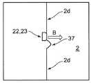
また、実施の形態1では、照明部22、23が照射する光がカメラ19のレンズ24へ直接的には到達しない場合について説明したが、このような場合に限らない。例えば、照明部22、23が照射する光がカメラ19のレンズ24へ直接的に到達するような配置であってもよい。このような場合には、照明部22、23とカメラ19のレンズ24との間に、照明部22、23による光を遮断する遮断部を設けても良い。これにより、カメラ19による視認性を向上させることができる。なお、この遮断部の形態としては、例えば、図6に示すような加熱室2の側壁面2dから突出する突出部37としてもよい。 In the first embodiment, the case where the light emitted from the
また、実施の形態1では、加熱室2の壁面自体が、照明部22、23からの光に対して反射率の低い材料(例えば、ホウロウ鋼板)により形成される場合について説明したが、このような場合に限らない。例えば、加熱室2の壁面自体は、反射率の低い材料とは異なる任意の材料(例えば、亜鉛やアルミメッキ鋼板、ステンレス鋼板)で形成しながら、一方で、反射率の低い材料(例えば、フッ素樹脂)を用いて当該壁面を覆うように形成(塗装等)するようにしても良い。このような場合であっても、照明部22、23による光の反射を抑制する効果を同様に奏することができる。また、反射率の低い材料を用いる際には、加熱室2の壁面全体ではなく、照明部22、23が設けられる側壁面2dに対向する側壁面2eにのみ適用してもよい。これにより、全ての壁面に当該材料を適用しなくとも、照明部22、23による光の反射を抑制する効果を効率的に発揮することができる。 Moreover, in
また、実施の形態1では、撮像部の一例として、レンズ24と撮像センサを備えたカメラ19について説明したが、このような場合に限らない。例えば、レンズを有しないカメラなど、撮像を行うものであれば任意の構成であってもよい。 In the first embodiment, the
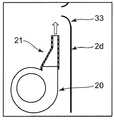
また、実施の形態1では、延出部31が側壁面2dから垂直に立ち上がって延びる場合について説明したが、このような場合に限らない。例えば、図5に示されるように、延出部33を湾曲するように形成しても良い。具体的には、図5に示すように、延出部33の外側における加熱室2の壁面との境界は、曲線状に湾曲しながら立ち上がるように形成されている。延出部33がこのような形状を呈することにより、加熱室2の側壁面2dから垂直に立ち上がる場合よりも、送風ファン20からの風と対向する領域において、乱流の発生を抑制して、気流の流れを整えることができる。これにより、送風ファン20による風(エアカーテン)が加熱室2内へ入ることを抑制することができる。 In the first embodiment, the case has been described in which the extending
また、実施の形態1では、加熱室2内を照明する照明部として、2つの照明部22、23を設ける場合について説明したが、個数は2つに限らず、例えば1つあるいは3つ以上設けてもよい。 In the first embodiment, the case where the two
また、実施の形態1では、加熱室2の側壁面2d側に照明部22、23(第1の照明部)を設ける場合について説明したが、このような場合に限らない。例えば、側壁面2dとは異なる壁面側に、別の照明部(第2の照明部)を設けても良い。このとき、図7に示すように、第2の照明部34、35を第1の照明部22、23と対向する加熱室2の側壁面2e側に設けてもよい。このような場合、カメラ19の撮像時において、順光の関係となる第1の照明部22、23を稼働させる一方で、カメラ19に対して逆光の関係となる第2の照明部34、35を停止させた状態とするようにしてもよい。具体的には、第1の照明部22、23と第2の照明部34、35による光の照射を制御する制御部36が、カメラ19による撮像を行う際に、第2の照明部34、35によって光を照射しないように、カメラ19および第2の照明部34、35を制御するようにしてもよい。このような制御により、カメラ19が配置されている側の壁面と対向する側に配置された第2の照明部を停止させて撮像を行うことにより、カメラ19に対して逆光となることを防ぐことができ、カメラ19による視認性をさらに向上させることができる。 Moreover, although
また、実施の形態1では、加熱室2の壁面における貫通孔として、カメラ19用の貫通孔25と蒸気供給部7用の蒸気供給孔12の2つのみを設ける場合について説明したが、このような場合に限らず、他の貫通孔を設けてもよい。例えば、加熱室2内の蒸気を加熱室2の外部へ排出するように、加熱室2の壁面において蒸気用の排出孔を設けても良い。これにより、特に蒸気供給部7を備えた構成においては、排出孔から蒸気を排出することができるため、カメラ19用の貫通孔25を通過しようとする蒸気の量を低減することができる。よって、カメラ19の信頼性を向上させることができる。なお、この場合の排出孔は、蒸気が上昇するため、加熱室2の壁面の中でも、高さ方向で1/2以上上方に配置することが好ましい。 In the first embodiment, the case where only two through
また、実施の形態1では、光の波長や角度に関する具体値や加熱室2の壁面を構成する材料の具体例を挙げて説明したが、これらは単なる例示であって、発明はこれらの例に限定されない。 In the first embodiment, specific values relating to the wavelength and angle of light and specific examples of the material constituting the wall surface of the
また、実施の形態1では、表示部5が液晶画面で構成される場合について説明したが、このような場合に限らず、表示機能を有したその他の形態であってもよい。また、実施の形態1では、操作部6が複数のボタンで構成される場合について説明したが、このような場合に限らず、ユーザによる操作が可能なその他の形態であってもよい。 In the first embodiment, the case where the
本発明は、食品を加熱して調理する加熱調理器であれば適用可能である。 The present invention is applicable to any cooking device that heats and cooks food.
1 加熱調理器
2 加熱室
3 本体
4 ドア
5 表示部
6 操作部
7 蒸気供給部
8 ヒータ加熱部
9 マイクロ波供給部
10 水タンク
11 蒸気用ヒータ
12 蒸気供給孔12
13 コンベクションヒータ
14 遠心ファン
15 マグネトロン
16a 導波管
16b アンテナ
17 インバータ
18 撮像ユニット
19 カメラ
20 送風ファン
21 送風ガイド
22、23 照明部(第1の照明部)
24 レンズ
25 貫通孔
26 第1の風路
27 空間
28 第3の風路
29 吸気口
30 排気口
31 延出部
32 外側側壁面
33 延出部
34、35 照明部(第2の照明部)
36 制御部
37 突出部(遮断部)DESCRIPTION OF
DESCRIPTION OF
24
36
Claims (5)
Translated fromJapanese加熱室の側壁面に形成された貫通孔と、
貫通孔を通じて加熱室内を撮像し、かつ撮像角度が下向きに設定された撮像部と、
撮像部の下方に配置され、加熱室の外側にて送風を行う送風部と、
送風部による風を撮像部の先端に下向きに配置されたレンズに向けて上方にガイドする送風ガイドと、を備え、
送風ガイドは、送風部からの風を撮像部の先端に下向きに配置されたレンズに衝突させるようにガイドするとともに、撮像部と貫通孔との間の空間を横切るエアカーテンを形成するように配置され、
貫通孔の内周から加熱室の外側に向って延出した延出部をさらに備える、加熱調理器。A heating chamber for storing food,
A through hole formed in the side wall surface of the heating chamber;
An imaging unit that images the heating chamber through the through-holeand the imaging angle is set downward ;
An air blower thatis arranged below the imaging unit and blows air outsidethe heating chamber;
An air guidethat guides air from the air blowing unitupward toward a lens disposed downward at the tip of the imaging unit , and
The air blowing guide guides the wind from the air blowing unitso as to collide with a lens disposed downward at the tip of the imaging unit, and is arranged so as to form an air curtain that crosses the space between the imaging unit and the through hole. And
A heating cooker further comprising an extending portion extending from the inner periphery of the through hole toward the outside of the heating chamber.
Priority Applications (5)
| Application Number | Priority Date | Filing Date | Title |
|---|---|---|---|
| JP2014209417AJP6579301B2 (en) | 2014-10-10 | 2014-10-10 | Cooker |
| PCT/JP2015/005138WO2016056246A1 (en) | 2014-10-10 | 2015-10-09 | Heating cooker |
| CN201580044203.3ACN106662332B (en) | 2014-10-10 | 2015-10-09 | Heating device |
| EP15848196.0AEP3205941B1 (en) | 2014-10-10 | 2015-10-09 | Heating cooker |
| US15/510,544US10524317B2 (en) | 2014-10-10 | 2015-10-09 | Heating cooker |
Applications Claiming Priority (1)
| Application Number | Priority Date | Filing Date | Title |
|---|---|---|---|
| JP2014209417AJP6579301B2 (en) | 2014-10-10 | 2014-10-10 | Cooker |
Publications (2)
| Publication Number | Publication Date |
|---|---|
| JP2016080210A JP2016080210A (en) | 2016-05-16 |
| JP6579301B2true JP6579301B2 (en) | 2019-09-25 |
Family
ID=55652880
Family Applications (1)
| Application Number | Title | Priority Date | Filing Date |
|---|---|---|---|
| JP2014209417AActiveJP6579301B2 (en) | 2014-10-10 | 2014-10-10 | Cooker |
Country Status (5)
| Country | Link |
|---|---|
| US (1) | US10524317B2 (en) |
| EP (1) | EP3205941B1 (en) |
| JP (1) | JP6579301B2 (en) |
| CN (1) | CN106662332B (en) |
| WO (1) | WO2016056246A1 (en) |
Families Citing this family (33)
| Publication number | Priority date | Publication date | Assignee | Title |
|---|---|---|---|---|
| WO2016196669A1 (en)* | 2015-06-01 | 2016-12-08 | June Life, Inc. | Thermal management system and method for a connected oven |
| WO2017090244A1 (en)* | 2015-11-27 | 2017-06-01 | パナソニックIpマネジメント株式会社 | Heating cooker, method for controlling heating cooker, and heating cooking system |
| WO2018044067A1 (en) | 2016-09-01 | 2018-03-08 | Samsung Electronics Co., Ltd. | Oven |
| JP6934607B2 (en)* | 2016-11-28 | 2021-09-15 | パナソニックIpマネジメント株式会社 | Cooker, cooker control method, and cooker system |
| CN108571757B (en) | 2017-03-08 | 2021-06-08 | 博西华电器(江苏)有限公司 | Range hood's camera device and range hood |
| KR102366006B1 (en)* | 2017-06-20 | 2022-02-23 | 삼성전자주식회사 | Oven |
| WO2019032876A1 (en) | 2017-08-09 | 2019-02-14 | Sharkninja Operating Llc | Cooking device and components thereof |
| DE102017220886A1 (en) | 2017-11-22 | 2019-05-23 | BSH Hausgeräte GmbH | Oven with sensor device and fan |
| KR102455063B1 (en)* | 2018-04-04 | 2022-10-14 | 엘지전자 주식회사 | Cooking appliance and method for controlling the same |
| JP7198972B2 (en) | 2018-04-27 | 2023-01-05 | パナソニックIpマネジメント株式会社 | heating cooker |
| JP7108820B2 (en)* | 2018-04-27 | 2022-07-29 | パナソニックIpマネジメント株式会社 | heating cooker |
| JP7108831B2 (en)* | 2018-04-27 | 2022-07-29 | パナソニックIpマネジメント株式会社 | heating cooker |
| JP7253680B2 (en)* | 2018-05-18 | 2023-04-07 | パナソニックIpマネジメント株式会社 | heating cooker |
| US20200154943A1 (en)* | 2018-11-16 | 2020-05-21 | GMG Products LLC | Imaging system for cooking device |
| US20200260539A1 (en)* | 2019-02-12 | 2020-08-13 | Scp Science | System and method for microwave digestion of a sample |
| WO2020176477A1 (en) | 2019-02-25 | 2020-09-03 | Sharkninja Operating Llc | Cooking system with guard |
| US11051654B2 (en) | 2019-02-25 | 2021-07-06 | Sharkninja Operating Llc | Cooking device and components thereof |
| DE102019206892A1 (en) | 2019-05-13 | 2020-11-19 | BSH Hausgeräte GmbH | Cooking appliance with sensor units arranged outside the cooking space |
| US20200408416A1 (en)* | 2019-06-26 | 2020-12-31 | Bsh Home Appliances Corporation | Transparent oven bottom |
| JP7394589B2 (en)* | 2019-11-12 | 2023-12-08 | エスペック株式会社 | Environment shaping device and imaging device for environment shaping device |
| DE102020108572A1 (en) | 2020-03-27 | 2021-09-30 | Rational Aktiengesellschaft | Cooking device with optics |
| US11678765B2 (en) | 2020-03-30 | 2023-06-20 | Sharkninja Operating Llc | Cooking device and components thereof |
| TWI724879B (en)* | 2020-04-27 | 2021-04-11 | 志勇無限創意有限公司 | Image capturing module and food processing device comprising the same |
| US11940153B2 (en) | 2020-12-01 | 2024-03-26 | GMG Products, LLC | Fuel conditioner for grill |
| US11747024B2 (en) | 2020-12-30 | 2023-09-05 | B/E Aerospace, Inc. | Oven air curtain |
| JP7482431B2 (en)* | 2021-06-30 | 2024-05-14 | パナソニックIpマネジメント株式会社 | Heating Cooker |
| JPWO2023090142A1 (en) | 2021-11-19 | 2023-05-25 | ||
| EP4487742A1 (en) | 2022-03-03 | 2025-01-08 | Gmg Outdoor Products (Wuhan) Co., Ltd | Grill |
| US12289508B2 (en) | 2022-03-18 | 2025-04-29 | GMG Products, LLC | Detachable camera for a smoker or grill |
| WO2024090750A1 (en)* | 2022-10-24 | 2024-05-02 | 삼성전자주식회사 | Cooking apparatus |
| BE1031879B1 (en) | 2023-08-09 | 2025-03-11 | Miele & Cie | Cooking appliance with camera device |
| DE102023121283A1 (en) | 2023-08-09 | 2025-02-13 | Miele & Cie. Kg | cooking appliance with camera device |
| US12359808B1 (en) | 2024-04-30 | 2025-07-15 | GMG Products, LLC | Variable fuel cooker |
Family Cites Families (17)
| Publication number | Priority date | Publication date | Assignee | Title |
|---|---|---|---|---|
| JPH067012B2 (en) | 1990-12-26 | 1994-01-26 | 三洋電機株式会社 | Cooking device |
| JPH06257756A (en)* | 1993-03-03 | 1994-09-16 | Toshiba Corp | microwave |
| JPH06307645A (en)* | 1993-04-26 | 1994-11-01 | Toshiba Corp | Heating and cooling device |
| CN2162055Y (en)* | 1993-04-27 | 1994-04-13 | 天津开发区中导实业公司 | Furnace wall type industry camera protective sleeve |
| JPH06347173A (en)* | 1993-06-03 | 1994-12-20 | Nippon Cement Co Ltd | Burning zone monitoring method for kiln |
| JP2000104930A (en)* | 1998-09-28 | 2000-04-11 | Sanyo Electric Co Ltd | Heating/cooking apparatus |
| JP2001056123A (en)* | 1999-08-12 | 2001-02-27 | Toshiba Corp | Microwave oven |
| JP3828319B2 (en)* | 1999-08-12 | 2006-10-04 | 株式会社東芝 | Microwave oven |
| JP2002243166A (en)* | 2001-02-20 | 2002-08-28 | Hitachi Hometec Ltd | Cooking device |
| JP2003056852A (en)* | 2001-08-09 | 2003-02-26 | Hitachi Hometec Ltd | Cooking device |
| JP2004263981A (en)* | 2003-03-04 | 2004-09-24 | Matsushita Electric Ind Co Ltd | High frequency heating equipment |
| JP4472412B2 (en) | 2004-04-22 | 2010-06-02 | パナソニック株式会社 | Cooker |
| JP2008292009A (en)* | 2007-05-22 | 2008-12-04 | Hoya Corp | Heating cooker |
| JP4825743B2 (en)* | 2007-06-27 | 2011-11-30 | 日立アプライアンス株式会社 | Cooker |
| JP4393541B2 (en)* | 2007-08-08 | 2010-01-06 | シャープ株式会社 | Packing, steam cooker, and method of manufacturing steam cooker |
| JP2010032149A (en)* | 2008-07-30 | 2010-02-12 | Panasonic Corp | Heating cooking device |
| KR101044147B1 (en) | 2009-06-15 | 2011-06-24 | 엘지전자 주식회사 | Cooking apparatus and control method |
- 2014
- 2014-10-10JPJP2014209417Apatent/JP6579301B2/enactiveActive
- 2015
- 2015-10-09CNCN201580044203.3Apatent/CN106662332B/enactiveActive
- 2015-10-09EPEP15848196.0Apatent/EP3205941B1/enactiveActive
- 2015-10-09WOPCT/JP2015/005138patent/WO2016056246A1/enactiveApplication Filing
- 2015-10-09USUS15/510,544patent/US10524317B2/enactiveActive
Also Published As
| Publication number | Publication date |
|---|---|
| US10524317B2 (en) | 2019-12-31 |
| US20170303348A1 (en) | 2017-10-19 |
| CN106662332A (en) | 2017-05-10 |
| EP3205941A4 (en) | 2017-10-11 |
| WO2016056246A1 (en) | 2016-04-14 |
| EP3205941A1 (en) | 2017-08-16 |
| CN106662332B (en) | 2019-09-17 |
| EP3205941B1 (en) | 2019-07-31 |
| JP2016080210A (en) | 2016-05-16 |
Similar Documents
| Publication | Publication Date | Title |
|---|---|---|
| JP6579301B2 (en) | Cooker | |
| JP6508625B2 (en) | Cooker | |
| US11585541B2 (en) | Heating cooking device | |
| CN101086341B (en) | heating cooker | |
| JP6101858B2 (en) | Cooker | |
| KR102363887B1 (en) | Light emitting door and cooking appliance therewith | |
| KR101064766B1 (en) | Steam Cooker | |
| JP6488177B2 (en) | Cooker | |
| JP7108820B2 (en) | heating cooker | |
| CN108119808A (en) | For the instruction device and household electrical appliance of household electrical appliance | |
| JP2019190772A (en) | Heating cooker | |
| JP6758336B2 (en) | Cooker | |
| JP5116863B2 (en) | Cooker | |
| KR102087974B1 (en) | Light emitting door and cooking appliance therewith | |
| JP7126046B2 (en) | heating cooker | |
| JP2017003153A (en) | High-frequency heating cooker | |
| JP6368652B2 (en) | Cooker | |
| JP6749280B2 (en) | Cooker | |
| JP7253680B2 (en) | heating cooker | |
| JP6682135B2 (en) | Cooking device | |
| JP6530973B2 (en) | High frequency heating cooker | |
| JP2017220387A (en) | Heating cooker | |
| JP2017003150A (en) | Cooker |
Legal Events
| Date | Code | Title | Description |
|---|---|---|---|
| A621 | Written request for application examination | Free format text:JAPANESE INTERMEDIATE CODE: A621 Effective date:20170719 | |
| A131 | Notification of reasons for refusal | Free format text:JAPANESE INTERMEDIATE CODE: A131 Effective date:20180731 | |
| A521 | Request for written amendment filed | Free format text:JAPANESE INTERMEDIATE CODE: A523 Effective date:20181001 | |
| A131 | Notification of reasons for refusal | Free format text:JAPANESE INTERMEDIATE CODE: A131 Effective date:20190305 | |
| A521 | Request for written amendment filed | Free format text:JAPANESE INTERMEDIATE CODE: A523 Effective date:20190408 | |
| TRDD | Decision of grant or rejection written | ||
| A01 | Written decision to grant a patent or to grant a registration (utility model) | Free format text:JAPANESE INTERMEDIATE CODE: A01 Effective date:20190806 | |
| A61 | First payment of annual fees (during grant procedure) | Free format text:JAPANESE INTERMEDIATE CODE: A61 Effective date:20190813 | |
| R151 | Written notification of patent or utility model registration | Ref document number:6579301 Country of ref document:JP Free format text:JAPANESE INTERMEDIATE CODE: R151 |