JP6578113B2 - Flying robot control system and flying robot - Google Patents
Flying robot control system and flying robotDownload PDFInfo
- Publication number
- JP6578113B2 JP6578113B2JP2015053580AJP2015053580AJP6578113B2JP 6578113 B2JP6578113 B2JP 6578113B2JP 2015053580 AJP2015053580 AJP 2015053580AJP 2015053580 AJP2015053580 AJP 2015053580AJP 6578113 B2JP6578113 B2JP 6578113B2
- Authority
- JP
- Japan
- Prior art keywords
- flight
- altitude
- flying robot
- monitoring
- flying
- Prior art date
- Legal status (The legal status is an assumption and is not a legal conclusion. Google has not performed a legal analysis and makes no representation as to the accuracy of the status listed.)
- Active
Links
Images


Landscapes
- Burglar Alarm Systems (AREA)
- Alarm Systems (AREA)
- Control Of Position, Course, Altitude, Or Attitude Of Moving Bodies (AREA)
- Manipulator (AREA)
Description
Translated fromJapanese本発明は、巡回経路を移動したり、任意に指定される移動目標位置に移動して警備情報を収集する飛行ロボットと、この飛行ロボットの飛行を制御する飛行ロボット制御システムに関する。 The present invention relates to a flying robot that moves on a patrol route or moves to an arbitrarily designated moving target position and collects security information, and a flying robot control system that controls the flight of the flying robot.
従来、各種の警備用センサを備えて所定の経路を巡回し、警備情報の収集をする移動ロボットが知られている。例えば下記特許文献1には、移動ロボットと遠隔の監視センタとの間で通信を行う制御装置が、警備装置の警備状態が警備になったことを判定すると、移動ロボットに施設警備信号を送信して、移動ロボットを所定の画像監視位置へ移動させ、移動ロボットが画像監視位置から送ってくる撮影画像を監視センタへ送信する提案がなされている。すなわち、特許文献1は、巡回タイミングにより予め設定された巡回経路を移動して警備情報を収集する移動ロボットについて、特に監視室が無人になると、特定の画像監視位置に移動して、以降は巡回タイミングになっても移動を抑制するよう制御するものである。 2. Description of the Related Art Conventionally, there has been known a mobile robot that includes various security sensors and circulates a predetermined route to collect security information. For example, in Patent Document 1 below, when a control device that communicates between a mobile robot and a remote monitoring center determines that the security status of the security device is in security, it transmits a facility security signal to the mobile robot. Thus, it has been proposed to move the mobile robot to a predetermined image monitoring position and to transmit the captured image sent from the image monitoring position to the monitoring center. That is, Patent Document 1 describes a mobile robot that collects security information by moving a patrol route set in advance according to the patrol timing, and moves to a specific image monitoring position when the monitoring room becomes unattended. Control is performed to suppress movement even at the timing.
上述した特許文献1では、自律走行の安全性を考慮して、遠隔から移動ロボットを緊急停止するための監視室が有人のときと無人のときとで移動ロボットによる巡回の挙動を異ならせている。 In Patent Document 1 described above, in consideration of the safety of autonomous traveling, the behavior of patrol by the mobile robot differs between when the monitoring room for emergency stop of the mobile robot from a remote location is manned and when it is unmanned. .
しかしながら、遠隔の監視室の有人無人と監視領域における現地の警備の必要性は異なる。監視領域全体のセキュリティ性を考慮すると、常に移動ロボットが巡回を行えることが好ましい。この場合、監視領域となる施設の職員や住人など、監視領域への存在が許可された利用者が監視領域内で活動を行う時間帯とそれ以外とで、考慮する条件が変わってくる。例えば、利用者が監視領域内で活動を行う時間帯には、移動ロボットと利用者の接触危険性が高まる。また、飛行手段により目標位置まで移動する飛行ロボットの場合には、低い高度で飛行する方が撮影画像など取得情報の精度が高まるが、飛行ロボットのプロペラ駆動音や風切り音が大きいために、特に夜間時においては周囲への騒音が問題になるおそれがある。 However, the need for local security in the surveillance area differs from manned and unmanned in remote surveillance rooms. Considering the security of the entire monitoring area, it is preferable that the mobile robot can always make patrols. In this case, the conditions to be considered vary depending on the time period during which a user who is permitted to exist in the monitoring area, such as a staff member or a resident of the facility serving as the monitoring area, performs activities in the monitoring area. For example, the risk of contact between the mobile robot and the user increases during the time when the user is active in the monitoring area. Also, in the case of a flying robot that moves to the target position by flying means, the accuracy of acquired information such as captured images increases when flying at a low altitude, but because the propeller driving sound and wind noise of the flying robot are large, especially Noise at the surroundings may be a problem at night.
そこで、本発明は上記問題点に鑑みてなされたものであり、飛行ロボットの行動や騒音による監視領域の利用者の妨げを低減することができる飛行ロボット制御システム及び飛行ロボットを提供することを目的とするものである。 Accordingly, the present invention has been made in view of the above problems, and an object of the present invention is to provide a flying robot control system and a flying robot that can reduce the disturbance of the user in the monitoring area due to the behavior and noise of the flying robot. It is what.
上記した目的を達成するために、本発明に係る飛行ロボット制御システムは、飛行手段を備えて、監視領域内において予め設定された監視位置に移動して警備情報を収集する飛行ロボットを制御する飛行ロボット制御システムであって、
前記監視位置の情報と、前記監視位置に移動するための一以上の飛行経路と、前記飛行経路において許容される飛行高度範囲と、前記飛行高度範囲において設定する飛行高度を少なくとも日中帯とそれ以外の各時間帯ごとに対応付けた飛行高度条件と、を記憶する記憶部と、
前記監視位置に移動するときに、当該監視位置への前記飛行経路に対応した飛行高度範囲と現在時刻に対応した前記飛行高度条件とから、前記飛行高度を決定する高度決定部と、
前記高度決定部にて決定した飛行高度で移動するよう前記飛行手段を駆動する飛行制御部と、
を備えたことを特徴とする。In order to achieve the above-described object, a flying robot control system according to the present invention includes a flying means and controls a flying robot that moves to a preset monitoring position in a monitoring area and collects security information. A robot control system,
And the said monitoring positioninformation, said and one or more flight path for moving the monitoringposition, wherein the flight altitude range allowed in the flightpath, it said flight middle zone at least the day of the flight altitude set in altitude range a storage unit thatstores, and altitudeconditions associated with each time slot other than,
When moving to the monitoring position, and advanced determination unit from said flight altitude conditions corresponding to flight altitude range and the current time corresponding to the flight path to the monitoring location to determinethe flight altitude,
A flight control unit that drives the flying means to move at a flight altitude determined by the altitude determining unit;
It is provided with.
また、本発明に係る飛行ロボット制御システムは、前記日中帯の方が前記それ以外よりも高い高度として条件設定されてもよい。Also, the flight robot control system according to the present invention may be a condition set as a higher altitude than the earlierSL daytime zonethe other.
さらに、本発明に係る飛行ロボット制御システムは、前記高度決定部が、前記監視領域において任意に指定された移動目標位置に移動するときは、基準位置から移動目標位置が遠いほど移動高度を高く設定してもよい。 Further, in the flying robot control system according to the present invention, when the altitude determination unit moves to a movement target position arbitrarily designated in the monitoring area, the movement altitude is set higher as the movement target position is farther from the reference position. May be.
また、本発明に係る飛行ロボットは、飛行手段を備えて、監視領域内において予め設定された監視位置に移動して警備情報を収集する飛行ロボットであって、
前記監視位置の情報と、前記監視位置に移動するための一以上の飛行経路と、前記飛行経路において許容される飛行高度範囲と、前記飛行高度範囲において設定する飛行高度を少なくとも日中帯とそれ以外の各時間帯ごとに対応付けた飛行高度条件と、を記憶する記憶部と、
前記監視位置に移動するときに、当該監視位置への前記飛行経路に対応した飛行高度範囲と現在時刻に対応した前記飛行高度条件とから、前記飛行高度を決定する高度決定部と、
前記高度決定部にて決定した飛行高度で移動するよう前記飛行手段を駆動する飛行制御部と、
を備えたことを特徴とする。Further, the flying robot according to the present invention is a flying robot that includes a flying means, moves to a monitoring position set in advance in a monitoring area, and collects security information.
And the said monitoring positioninformation, said and one or more flight path for moving the monitoringposition, wherein the flight altitude range allowed in the flightpath, it said flight middle zone at least the day of the flight altitude set in altitude range a storage unit thatstores, and altitudeconditions associated with each time slot other than,
When moving to the monitoring position, and advanced determination unit from said flight altitude conditions corresponding to flight altitude range and the current time corresponding to the flight path to the monitoring location to determinethe flight altitude,
A flight control unit that drives the flying means to move at a flight altitude determined by the altitude determining unit;
It is provided with.
本発明の飛行ロボット制御システムによれば、記憶部は、監視位置の情報と、監視位置に移動するための一以上の飛行経路と、飛行経路において許容される飛行高度範囲と、飛行高度範囲において設定する飛行高度を少なくとも日中帯とそれ以外の各時間帯ごとに対応付けた飛行高度条件と、を記憶する。高度決定部は、監視位置に移動するときに、監視位置への飛行経路に対応した飛行高度範囲と現在時刻に対応した飛行高度条件とから、飛行高度を決定する。飛行制御部は、高度決定部にて決定した飛行高度で移動するよう飛行手段を駆動する。かかる構成により、現在時刻に応じて監視位置に移動するときの飛行高度を決定し、決定した飛行高度で移動することができる。そして、時間帯で監視位置間の飛行高度を異ならせて飛行ロボットを巡回させるので、飛行ロボットの行動や騒音による監視領域の利用者への邪魔を防止することができる。According to the flying robot control system of the present invention, the storage unit includes information onthe monitoring position, one or more flight paths for moving tothe monitoring position, a flight altitude range permitted inthe flight path, anda flight altitude range. medium band at least the day of the flight altitude setting and the flight altitudeconditions associated with each other each timezone, and stores the. The altitude determining unit determines the flight altitude from the flight altitude range corresponding to the flight path to the monitoring position and the flight altitude condition corresponding to the current time when moving to the monitoring position. The flight control unit drives the flying means to move at the flight altitude determined by the altitude determining unit. With this configuration, it is possible to determine the flight altitude when moving to the monitoring position according to the current time, and to move at the determined flight altitude. And since the flight robot is circulated by changing the flight altitude between the monitoring positions in the time zone, it is possible to prevent the monitoring area from being disturbed by the behavior of the flying robot and the noise.
また、本発明の飛行ロボット制御システムによれば、日中帯の方がそれ以外よりも高い高度として条件設定する。かかる構成により、日中帯はそれ以外の時間帯よりも監視領域内で活動する人が多いため、飛行ロボットが低い高度で飛行する際の妨げになるが、日中帯の方がそれ以外よりも高い高度に条件設定して飛行ロボットを飛行させるので、監視領域で飛行ロボットが人と接触する危険性が低減し、飛行ロボットを高い飛行高度で高速に飛行させることができる。Further, according to the flight robot control system of the presentinvention, towards thedaytime zone conditions set as higher altitude than others. With this configuration, there are more people working in the surveillance area in the daytime zone than in other time zones, which hinders flying robots from flying at low altitudes. Since the flying robot is made to fly at a high altitude condition, the risk of the flying robot coming into contact with a person in the monitoring area is reduced, and the flying robot can fly at a high flying altitude at high speed.
さらに、本発明の飛行ロボット制御システムによれば、高度決定部は、監視領域において任意に指定された移動目標位置に移動するときは、基準位置(例えば飛行ロボットが待機するロボポートの中心位置)から移動目標位置が遠いほど移動高度を高く設定する。かかる構成により、基準位置から移動目標位置が遠いときに飛行ロボットを高い飛行高度で高速に移動させることができ、移動目標位置まで早く到達させることができる。 Further, according to the flying robot control system of the present invention, when the altitude determining unit moves to the movement target position arbitrarily designated in the monitoring area, the altitude determining unit starts from the reference position (for example, the center position of the robot port where the flying robot waits). The higher the moving altitude, the higher the moving altitude. With this configuration, when the movement target position is far from the reference position, the flying robot can be moved at a high speed at a high flight altitude, and the movement target position can be reached quickly.
また、本発明の飛行ロボットによれば、記憶部は、監視位置の情報と、監視位置に移動するための一以上の飛行経路と、飛行経路において許容される飛行高度範囲と、飛行高度範囲において設定する飛行高度を少なくとも日中帯とそれ以外の各時間帯ごとに対応付けた飛行高度条件と、を記憶する。高度決定部は、監視位置に移動するときに、監視位置への飛行経路に対応した飛行高度範囲と現在時刻に対応した飛行高度条件とから、飛行高度を決定する。飛行制御部は、高度決定部にて決定した飛行高度で移動するよう飛行手段を駆動する。かかる構成により、飛行ロボットは、自身の判断により現在時刻に応じて監視位置に移動するときの飛行高度を決定し、決定した飛行高度で移動することができる。そして、時間帯で監視位置間の飛行高度を異ならせて飛行ロボットが巡回するので、飛行ロボットの行動や騒音による監視領域の利用者への邪魔を防止することができる。According to the flying robot of the present invention, the storage unit includes information onthe monitoring position, one or more flight paths for moving tothe monitoring position, a flight altitude range permitted inthe flight path, anda flight altitude range. medium band at least the day of the flight altitude setting and the flight altitudeconditions associated with each other each timezone, and stores the. The altitude determining unit determines the flight altitude from the flight altitude range corresponding to the flight path to the monitoring position and the flight altitude condition corresponding to the current time when moving to the monitoring position. The flight control unit drives the flying means to move at the flight altitude determined by the altitude determining unit. With this configuration, the flying robot can determine the flight altitude when moving to the monitoring position according to the current time according to its own determination, and can move at the determined flight altitude. And since the flying robot circulates by changing the flight altitude between the monitoring positions in the time zone, it is possible to prevent the monitoring area from being disturbed by the behavior of the flying robot and the noise.
以下、本発明を実施するための形態について、添付した図面の図1〜5を参照しながら詳細に説明する。 Hereinafter, embodiments for carrying out the present invention will be described in detail with reference to FIGS. 1 to 5 of the accompanying drawings.
[本発明の概要について]
本発明は、予め設定される巡回スケジュールの巡回経路(飛行経路)を移動したり、任意に指定される移動目標位置に移動して警備情報を収集する飛行ロボットと、この飛行ロボットの飛行を制御する飛行ロボット制御システムに関する。この飛行ロボット制御システムにおける飛行ロボットは、平常時における監視領域の安全確認を行うための巡回飛行として、重要監視位置を移動しつつ、重要監視位置にて一定時間停止して監視動作(例えば撮影部による撮影)を行う。なお、重要監視位置は本発明における監視位置の一例である。この監視動作を行うにあたっては、時間帯に応じた重要監視位置間(飛行ロボットが離着陸する位置と最初と最後の重要監視位置との間を含む)の飛行高度を設定する高度設定処理を実行し、時間帯で重要監視位置間の飛行高度を異ならせて飛行ロボットを巡回させる。これにより、飛行ロボットの行動や騒音による監視領域の利用者への邪魔を防止する飛行ロボット制御システムや飛行ロボットを実現する。[Outline of the present invention]
The present invention controls a flying robot that moves a patrol route (flight route) of a preset patrol schedule, moves to an arbitrarily designated moving target position, and collects security information, and controls the flight of the flying robot. The present invention relates to a flying robot control system. The flying robot in this flying robot control system, as a traveling flight for confirming the safety of the monitoring area in normal times, moves at the important monitoring position and stops for a certain time at the important monitoring position (for example, the photographing unit). Shooting). The important monitoring position is an example of the monitoring position in the present invention. In performing this monitoring operation, altitude setting processing is performed to set the flight altitude between important monitoring positions (including between the position where the flying robot takes off and landing and the first and last important monitoring positions) according to the time zone. The flying robots are patrolled by changing the flight altitude between the important monitoring positions in the time zone. As a result, a flying robot control system and a flying robot that prevent the user in the monitoring area from being disturbed by the behavior and noise of the flying robot are realized.
[飛行ロボット制御システムの構成について]
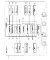
図1及び図2に示すように、本実施の形態の飛行ロボット制御システム1は、ロボポート2、飛行ロボット3、飛行制御装置4、監視センタ5によって構築される。この飛行ロボット制御システムにおける飛行ロボット3は、図1において、例えばロボポート2(基準位置P0)→重要監視位置P1→重要監視位置P2→重要監視位置P3→重要監視位置P4→重要監視位置P5→ロボポート2(基準位置P0)の順番に巡回経路が決められた巡回番号1の巡回を行う場合、ロボポート2から離陸した後、P1→P2→P3→P4→P5の順番に移動して巡回し、P1〜P5で一定時間停止して警備情報(例えば撮影画像)を収集してロボポート2に帰還する。なお、飛行ロボット3は移動中も警備情報を収集してもよい。飛行ロボット3が収集した警備情報は、飛行制御装置4を介して監視センタ5に送信される。監視センタ5は、飛行ロボット3から飛行制御装置4を介して送信される警備情報をモニタに表示し、監視領域Eにおける巡回経路上や重要監視位置に異常が無いかの安全確認を行う。以下、飛行ロボット制御システム1を構築する各部の構成について説明する。[Configuration of flying robot control system]
As shown in FIGS. 1 and 2, the flying robot control system 1 of the present embodiment is constructed by a
なお、本例において、重要監視位置とは、全体が監視される監視領域Eの中でも重要な位置とされ、飛行ロボット3が巡回経路(飛行経路)上で必ず停止する位置である。また、利用者とは、監視領域Eへの存在が許可された人であり、監視領域Eへの存在が許可されていない外部からの侵入者を除くものである。 In this example, the important monitoring position is an important position in the monitoring area E that is monitored as a whole, and is a position where the flying robot 3 always stops on the patrol route (flight route). The user is a person who is permitted to exist in the monitoring area E, and excludes an intruder from outside who is not permitted to exist in the monitoring area E.
[ロボポートの構成について]
ロボポート2は、飛行ロボット3の待機場所であり、飛行制御装置4からの指示を受け、飛行ロボット3の離陸や着陸を行うための設備を備える。また、ロボポート2は、飛行ロボット3が着陸するときに飛行ロボット3をポート内に収容する機構を備え、飛行ロボット3をポート内に収容したときに、飛行ロボット3に対して接触又は非接触にて給電を行う機能を有する。[Roboport configuration]
The
[飛行ロボットの構成について]
飛行ロボット3は、飛行制御装置4から飛行指示を受けていない通常の状態ではロボポート2(基準位置P0)に待機しており、飛行制御装置4からの飛行指示により予め設定された巡回スケジュールの時刻になると巡回経路(飛行経路)を巡回飛行したり、監視センタ5からの指示により指定された移動目標位置に向かって飛行する。[Configuration of flying robot]
The flying robot 3 stands by at the roboport 2 (reference position P0) in a normal state where it has not received a flight instruction from the
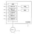
飛行ロボット3は、図3に示すように、ロータ11、ロータ駆動部12、飛行状態検知部13、位置情報受信部14、高度センサ15、撮影部16、照明17、アンテナ18、測距センサ19、照度センサ20、記憶部21、電源22、ロボ制御部23を備える。 As shown in FIG. 3, the flying robot 3 includes a
ロータ11は、例えば4つの回転体で構成され、飛行ロボット3の機体を上昇・下降・方向転換、前進などの飛行をするようにロータ駆動部12によって駆動される。 The
ロータ駆動部12は、飛行ロボット3の機体を上昇・下降・方向転換、前進などの飛行をするため、後述するロータ制御手段33bの制御により、ロータ11の各回転体を駆動する。 The
飛行状態検知部13は、飛行ロボット3の飛行状態を検知するものであり、例えば飛行ロボット3の向きを検知する方位センサ、飛行ロボット3の姿勢や加速度を検知する加速度センサやジャイロセンサなどの各種センサで構成される。これら各種センサの検知結果は、飛行ロボット3の飛行状態情報として後述する姿勢制御手段33に入力される。 The flight state detection unit 13 detects the flight state of the flying robot 3. For example, the flight state detection unit 13 detects various directions such as an orientation sensor that detects the orientation of the flying robot 3, an acceleration sensor that detects the attitude and acceleration of the flying robot 3, and a gyro sensor. Consists of sensors. The detection results of these various sensors are input to the attitude control means 33 described later as flight state information of the flying robot 3.
位置情報受信部14は、例えば全地球測位システム(GNSS:Global Navigation Satellite System)などの衛星測位システムを利用し、飛行ロボット3の現在位置を検知する。位置情報受信部14にて検知した飛行ロボット3の現在位置は、飛行ロボット3の位置情報(GNSS信号)として後述する自己位置測位手段33aに入力される。 The position
高度センサ15は、ロボ制御部23の制御により、気圧センサの気圧値や飛行ロボット3の機体から鉛直下方に投受光されるレーザなどにより飛行ロボット3の現在高度を計測する。高度センサ15にて計測した飛行ロボット3の現在高度は、高度情報として後述する自己位置測位手段33aに入力される。 The altitude sensor 15 measures the current altitude of the flying robot 3 based on the barometric pressure value of the barometric sensor or a laser light projected and received vertically from the body of the flying robot 3 under the control of the
撮影部16は、例えば撮像素子を用いたカメラで構成され、飛行ロボット3の周囲(例えば前方や下方など)をカラー画像にて撮影する。撮影部16は、後述する撮影制御手段34により撮影の許可(禁止解除)・禁止、撮影角度が制御される。撮影部16にて撮影した画像は、後述する撮影制御手段34に入力される。 The
照明17は、撮影部16による撮影を補助するLED照明などの照明器具で構成され、後述する照明制御手段35により点灯・消灯が制御される。照明17は、飛行ロボット3が設定高度未満を飛行中の条件下において、飛行中の飛行ロボット3の周囲が暗くなって設定照度以下となったときに点灯する。これに対し、照明17は、飛行ロボット3が設定高度以上を飛行中の条件下において点灯が禁止される。 The
アンテナ18は、ロボット本体に設けられ、小電力無線、WiFi通信などにより飛行制御装置4との間で無線通信を行う。 The
測距センサ19は、ロボ制御部23の制御により、飛行ロボット3の機体の水平方向又は鉛直下方に電磁波、可視光線、音波などを投受光し、飛行ロボット3の機体と周辺との距離を計測する。測距センサ19としては、例えばレーザセンサ、マイクロ波センサ、赤外線センサ、超音波センサなどを用いることもできる。測距センサ19による計測結果は、飛行ロボット3の周囲情報として後述する障害物検知手段32に入力される。 The ranging
照度センサ20は、必要に応じて設けられるものであり、飛行ロボット3の周囲の明るさを検出する。照度センサ20の検出結果は、照度情報として後述する照明制御手段35に入力される。 The illuminance sensor 20 is provided as necessary, and detects the brightness around the flying robot 3. The detection result of the illuminance sensor 20 is input to the illumination control means 35 described later as illuminance information.
記憶部21は、飛行ロボット3が飛行中のときに撮影部16が撮影した画像を逐次記憶する。 The storage unit 21 sequentially stores images captured by the
電源22は、例えばリチウムポリマー電池などの充電式電池で構成され、飛行ロボット3の各部に必要な電力を供給する。 The
ロボ制御部23は、飛行ロボット3の全体を統括制御するものであり、図3に示すように、通信制御手段31、障害物検知手段32、姿勢制御手段33、撮影制御手段34、照明制御手段35を備える。 The
通信制御手段31は、アンテナ18を介して飛行制御装置4と無線通信を行い、各種情報(飛行制御装置4から飛行ロボット3への巡回ルート指示、移動目標位置や速度の指示、離陸指示、帰還指示、飛行ロボット3から飛行制御装置4への飛行状態情報、位置情報、高度情報など)の送受信を行う。また、通信制御手段31は、撮影部16が撮影したライブ画像を無線通信により飛行制御装置4に送信する。 The communication control means 31 wirelessly communicates with the
障害物検知手段32は、測距センサ19にて検知した飛行ロボット3の周囲情報に基づいて飛行ロボット3の周辺における障害物の有無を判定する。 The obstacle detection means 32 determines the presence or absence of an obstacle around the flying robot 3 based on the surrounding information of the flying robot 3 detected by the
姿勢制御手段33は、飛行状態検知部13からの各種検知信号、位置情報受信部14からの位置情報、高度センサ15からの高度情報に基づいて飛行ロボット3の飛行中の姿勢を制御するものであり、自己位置測位手段33a、ロータ制御手段33bを備える。 The attitude control means 33 controls the attitude of the flying robot 3 in flight based on various detection signals from the flight state detector 13, position information from the
自己位置測位手段33aは、位置情報受信部14が受信した位置情報(GNSS信号)、及び高度センサ15が測定した高度情報を用いて自己位置(緯度、経度、高度)を算出する。 The self-positioning means 33a calculates the self-position (latitude, longitude, altitude) using the position information (GNSS signal) received by the position
ロータ制御手段33bは、飛行制御装置4から飛行指示を受けると、現在の飛行経路に対応して後述する記憶部42に記憶された高度テーブルの飛行高度を中心として障害物を回避しながら移動するようにロータ駆動部12を制御して飛行ロボット3の高度や速度を制御する。 When the rotor control means 33b receives a flight instruction from the
撮影制御手段34は、撮影部16の撮影開始や終了、撮影部16が撮影した画像を取得して通信制御手段31から飛行制御装置4へライブ画像を送信するなどの処理を行う。また、撮影制御手段34は、飛行制御装置4からの指示に従って撮影の許可(禁止解除)/禁止、撮影角度の制御を行う。 The
照明制御手段35は、撮影画像の輝度情報、あるいは必要に応じて設けられた照度センサ20の照度情報を飛行制御装置4に送信し、この送信に伴う飛行制御装置4からの指示に従って照明17のオン/オフを制御する。 The illumination control means 35 transmits the brightness information of the captured image or the illuminance information of the illuminance sensor 20 provided as necessary to the
なお、照明制御手段35は、撮影画像の輝度情報、又は照度センサ20の照度情報から飛行ロボット3の周囲の照度が設定照度以下か否かを判別し、この判別結果を飛行制御装置4に送信することもできる。 The
[飛行制御装置の構成について]
飛行制御装置4は、例えば監視領域内の所定箇所や監視領域近傍に設置される。飛行制御装置4は、飛行ロボット3との間で無線通信し、飛行ロボット3から送信される各種情報に基づき、飛行ロボット3に各種制御指示を行う監視装置の機能を備える。なお、飛行制御装置4は、監視センタ5の監視卓5aから任意に指定された移動目標位置への飛行ロボット3の飛行指示、飛行ロボット3による撮影指示等の各種指示を受信すると、飛行ロボット4に各種制御指示を行う。[Configuration of flight control device]
The
飛行制御装置4は、飛行ロボット3の飛行を制御するものであり、図4に示すように、通信部41、記憶部42、制御部43を備える。 The
通信部41は、飛行ロボット3との間で例えば小電力無線やWiFi通信などの無線通信を行い、飛行ロボット3から飛行状態情報としての位置(緯度、経度、高度)、速度等の情報を受信し、この受信した情報に応じた各種制御信号を飛行ロボット3に送信する。また、通信部41は、監視センタ5の監視卓5aから飛行ロボット3の飛行指示を受信すると、この飛行指示に従った各種制御信号を飛行ロボット3に送信する。さらに、通信部41は、飛行ロボット3の撮影部16が撮影した画像をインターネット等の広域ネットワーク(WAN)上に構築された仮想専用ネットワーク(VPN)を介して監視センタ5に送信する。 The
記憶部42は、例えばROM,RAMなどで構成され、基準位置となるロボポート2の位置情報、飛行経路(巡回経路)、重要監視位置情報、飛行高度範囲(巡回高度範囲)、飛行高度条件、巡回スケジュールを記憶している。飛行経路は、重要監視位置に移動するための少なくとも1つ以上の経路である。重要監視位置情報は、飛行経路毎に付与される巡回番号と、この巡回番号に対応する複数の重要監視位置の位置座標情報(例えば飛行領域マップ上の緯度、経度)、各重要監視位置間の移動区間を識別する移動区間情報(飛行ロボット3が離着陸するロボポート2と最初と最後の重要監視位置との間の移動区間情報を含む)である。飛行高度範囲は、飛行経路の移動区間毎に飛行が許容される高度範囲(例えば地表から5〜10mの範囲)である。飛行高度条件は、時間帯に対応した飛行高度の条件であり、少なくとも日中帯とそれ以外(例えば夜間帯、深夜帯)とを含み、日中帯の方がそれ以外よりも高い高度として条件設定される。巡回スケジュールは、監視領域Eにおけるどの重要監視位置をどの順番でいつ巡回するかを示す日程であり、監視センタ5の監視卓5aの操作により予め監視領域E毎に設定される。 The
また、記憶部42は、飛行ロボット3が飛行する領域を緯度、経度、高度の3次元にて表現した飛行領域マップ、監視領域Eに関する各種情報である監視領域情報、飛行ロボット3と通信を行うためのデータや飛行ロボット3の飛行を制御するための各種パラメータ、これら以外に飛行制御装置4の機能を実現するための各種プログラムが記憶されている。 In addition, the
制御部43は、記憶部42からソフトウェアモジュールを読み出し、CPU等にて各処理を行い、各部を統括制御するものであり、高度決定手段43a、高度テーブル生成手段43b、飛行制御手段43c、撮影制御手段43d、状態確認手段43eを備える。 The
高度決定手段43aは、各重要監視位置P1〜P5に移動するときに、各重要監視位置P1〜P5への飛行経路(移動区間M1〜M6)毎に対応した飛行高度範囲(巡回高度範囲)と、現在時刻(実際に飛行ロボット3が各重要監視位置間を巡回する時刻)に対応した飛行高度条件とによって飛行高度を決定する。例えば巡回時間帯が日中帯(例えば7:00〜19:00)であれば、飛行高度範囲(例えば5〜10m)の上限値あるいはその近傍の高度(例えば9.5m)を飛行高度として決定する。巡回時間帯が夜間帯(例えば19:00〜0:00)であれば、飛行高度範囲(例えば5〜10m)の中央値あるいはその近傍の高度(例えば7m)を飛行高度として決定する。巡回時間帯が深夜帯(例えば0:00〜7:00)であれば、飛行高度範囲(例えば5〜10m)の下限値あるいはその近傍の高度(例えば5.5m)を飛行高度として決定する。なお、巡回の時間帯により飛行高度範囲からどのように飛行高度を設定するかは、予め飛行高度条件として記憶されている。 When the altitude determination means 43a moves to each of the important monitoring positions P1 to P5, the altitude determination means 43a has a flight altitude range (cyclic altitude range) corresponding to each flight route (movement section M1 to M6) to each of the important monitoring positions P1 to P5. The flight altitude is determined according to the flight altitude condition corresponding to the current time (the time when the flying robot 3 actually circulates between the important monitoring positions). For example, if the traveling time zone is the daytime zone (for example, 7:00 to 19:00), the upper limit value of the flight altitude range (for example, 5 to 10 m) or the altitude in the vicinity (for example, 9.5 m) is determined as the flight altitude. To do. If the traveling time zone is a night zone (for example, 19:00 to 0:00), the median value of the flight altitude range (for example, 5 to 10 m) or the altitude in the vicinity (for example, 7 m) is determined as the flight altitude. If the traveling time zone is midnight (for example, 0:00 to 7:00), the lower limit value of the flight altitude range (for example, 5 to 10 m) or the altitude in the vicinity (for example, 5.5 m) is determined as the flight altitude. Note that how to set the flight altitude from the flight altitude range according to the traveling time zone is stored in advance as a flight altitude condition.
ここで、巡回時間帯が日中帯のときに飛行高度を飛行高度範囲の上限値あるいはその近傍にしているのは、日中帯では監視領域E内で活動する利用者も多く、利用者と接触する危険性を低減するとともに、障害物の少ない上空を高速で飛行して移動目標位置まで迅速に移動するためである。また、巡回時間帯が深夜帯のときに飛行高度を飛行高度範囲の下限値あるいはその近傍にしているのは、低い高度でより精細に撮影画像などの警備情報を取得するためである。また、飛行移動している飛行ロボット3のプロペラ駆動音や風切り音の反響が広域に拡がるのを低減することもできる。 Here, when the traveling time zone is the daytime zone, the flight altitude is set to the upper limit value of the flight altitude range or in the vicinity thereof. In the daytime zone, there are many users who are active in the monitoring area E. This is because the risk of touching is reduced, and the aircraft moves quickly to the moving target position by flying at high speed in the sky with few obstacles. Also, the reason why the flight altitude is set to the lower limit value of the flight altitude range or in the vicinity thereof when the traveling time zone is in the middle of the night is to obtain security information such as a captured image more precisely at a low altitude. In addition, it is possible to reduce the spread of the propeller driving sound and wind noise of the flying robot 3 moving in flight over a wide area.
なお、巡回時間帯に対応した飛行高度条件は、少なくとも日中帯とそれ以外とを含んでおり、日中帯の方がそれ以外よりも高い高度として条件設定されていればよい。また、日中帯の時間範囲は、監視領域Eにおける利用者の活動時間に応じて適宜設定される。 Note that the flight altitude condition corresponding to the traveling time zone includes at least the daytime zone and the rest, and the daytime zone may be set as a higher altitude than the other. Further, the time range of the daytime zone is appropriately set according to the activity time of the user in the monitoring area E.
高度テーブル生成部43bは、高度決定手段43aにて決定した飛行高度を飛行経路(移動区間M1〜M6)に対応付けた高度テーブルとして記憶部42に記憶する。 The altitude
飛行制御手段43cは、通信部41を介して飛行ロボット3から飛行状態情報、位置情報、高度情報を取得し、飛行ロボット3の移動目標位置、速度などの飛行ロボット3の飛行に関わる制御信号を飛行ロボット3に通信部41を介して送信し、飛行ロボット3の飛行を制御する。例えば飛行ロボット3の飛行高度が予め設定された設定高度以上であれば、飛行ロボット3が高速(例えば5〜15m/s)で飛行するように速度を制御する。また、飛行ロボット3の飛行高度が設定高度未満であれば、飛行ロボット3が基準速度以下の低速(例えば2〜3m/s:障害物を検知したときに回避可能な速度)で飛行するように速度を制御する。 The
撮影制御手段43dは、飛行ロボット3の撮影部16による撮影を制御するもので、通信部41を介して飛行ロボット3から取得した現在位置における高度情報に基づいて撮影許可信号(撮影禁止解除信号)又は撮影禁止信号を通信部41を介して飛行ロボット3に送信する。例えば現在位置における飛行ロボット3の高度情報が設定高度以上のときは、撮影部16の撮影を禁止する撮影禁止信号を通信部41を介して飛行ロボット3に送信する。これに対し、現在位置における飛行ロボット3の高度情報が設定高度未満のときは、撮影部16の撮影を許可する撮影許可信号(撮影禁止解除信号)を通信部41を介して飛行ロボット3に送信する。なお、撮影制御手段43dは、必要に応じて撮影部16の撮影角度を制御するための撮影角度制御信号を通信部41を介して飛行ロボット3に送信することもある。 The imaging control means 43d controls imaging by the
また、撮影制御手段43dは、飛行ロボット3から取得した撮影画像の輝度情報や照度情報を用いて、飛行中の飛行ロボット3の周囲の照度が設定照度以下か否かを判別し、この判別結果と上述した高度情報に基づいて飛行ロボット3の照明17をオン/オフするオン/オフ制御信号を飛行ロボット3に送信する。例えば飛行ロボット3が設定照度以下の夜間を飛行中で、かつ飛行ロボット3が設定高度以上を飛行中のときは、照明17の点灯を禁止するためオフ制御信号を通信部41を介して飛行ロボット3に送信する。これに対し、飛行ロボット3が設定照度以下の夜間を飛行中で、かつ飛行ロボット3が設定高度未満を飛行中のときは、照明17を点灯するためオン制御信号を通信部41を介して飛行ロボット3に送信する。 Further, the
なお、飛行中の飛行ロボット3の周囲の照度が設定照度以下か否かを示す判別結果が飛行ロボット3から送信される場合には、この判別結果に基づいて飛行ロボット3の照明17をオン/オフするオン/オフ制御信号を撮影制御手段43bが飛行ロボット3に送信する。また、飛行中の飛行ロボット3の周囲の照度が設定照度以下か否かの判別には、現在時刻を用いることもできる。 When a determination result indicating whether or not the illuminance around the flying robot 3 in flight is equal to or lower than the set illuminance is transmitted from the flying robot 3, the
状態確認手段43eは、飛行ロボット3の状態を確認するもので、飛行ロボット3がロボポート2に待機しているときに定期的に飛行ロボット3の機能が正常か否かを確認する。 The
[監視センタの構成について]
監視センタ5は、図2に示すように、飛行ロボット3が撮影した映像を飛行制御装置4を介して受信し、受信した映像を表示する端末装置などの監視卓5aを備える。また、監視センタ5は、監視卓5aの操作により後述する高度設定処理の開始を指示することもできる。さらに、監視センタ5は、監視員の判断によって監視卓5aを操作することにより任意の場所に飛行ロボット3を向かわせる飛行指示(飛行ルート指示、移動目標位置や速度の指示、離陸指示、帰還指示など)を行うこともできる。例えば監視員が監視卓5aに表示された映像から監視領域E内への侵入物体(例えば不審車両や不審者など)を発見した場合、監視員が監視卓5aを操作して飛行ロボット3を現場に向かわせる移動目標位置(緯度、経度)を設定し、この設定された移動目標位置を制御信号として、飛行制御装置4を介して飛行ロボット3に送信する。[About monitoring center configuration]
As shown in FIG. 2, the
[高度設定処理について]
次に、飛行制御装置4が実行する高度設定処理について図5を参照しながら説明する。この高度設定処理によって設定された高度は、飛行ロボット3が複数の重要監視位置を移動しつつ、重要監視位置にて一定時間停止して監視動作を行う巡回飛行をする際に用いられる。ここでは、図1の示す巡回番号1の飛行経路(移動区間M1〜M6)を飛行ロボット3が巡回する場合の高度設定処理を例にとって説明する。[About advanced settings processing]
Next, altitude setting processing executed by the
図5の高度設定処理は、巡回スケジュールとして設定された巡回開始時刻の所定時間前、遠隔の監視センタ5から手動操作による巡回開始の入力があったとき、予め設定された巡回パラメータの生成時刻の何れかのタイミングで開始される。例えば図1に示す巡回番号1の巡回経路を9:00から2時間おきに巡回する巡回スケジュールの場合には、所定時間が例えば15分であれば、9:00の15分前の8:45に高度設定処理を開始する。 In the altitude setting process of FIG. 5, when a tour start is input manually from the
上記のタイミングで高度設定処理が開始すると、飛行ロボット3が巡回する巡回番号の巡回地点情報を読み出す(ST1)。図1に示す巡回番号1の飛行経路を飛行ロボット3が巡回する場合、巡回番号1の巡回地点情報、すなわち、重要監視位置P1〜P5の重要監視位置情報を記憶部42から読み出す。 When the altitude setting process starts at the above timing, the patrol point information of the patrol number that the flying robot 3 patrols is read (ST1). When the flying robot 3 patrols the flight route of the tour number 1 shown in FIG. 1, the tour point information of the tour number 1, that is, the important monitoring position information of the important monitoring positions P <b> 1 to P <b> 5 is read from the
次に、巡回地点情報に基づく移動区間毎の飛行高度範囲(巡回高度範囲)の情報を読み出す(ST2)。図1に示す巡回番号1の飛行経路では、ロボポート2と最初の重要監視位置P1との間の移動区間M1、各重要監視位置P1〜P5間の移動区間M2,M3,M4,M5、最後の重要監視位置P5とロボポート2との間の移動区間M6における飛行高度範囲の情報を記憶部42から読み出す。 Next, information on the flight altitude range (touring altitude range) for each moving section based on the patrol point information is read (ST2). In the flight route of the patrol number 1 shown in FIG. 1, the moving section M1 between the
次に、ロボポート2から最初の地点(最初の重要監視位置)までの区間(移動区間)を選択する(ST3)。図1に示す巡回番号1の飛行経路では、ロボポート2から最初の重要監視位置P1までの移動区間M1を選択する。 Next, a section (moving section) from the
次に、選択した区間の巡回時間帯を判別し(ST4)、選択されている区間の飛行高度(巡回高度)として、飛行高度範囲の中から巡回時間帯に基づいて決定する(ST5)。ここでは例えば巡回時間帯が日中帯(例えば7:00〜19:00)であれば、飛行高度範囲(例えば5〜10m)の上限値(例えば10m)を飛行高度として決定する。巡回時間帯が夜間帯(例えば19:00〜0:00)であれば、飛行高度範囲(例えば5〜10m)の中央値(例えば7.5m)を飛行高度として決定する。巡回時間帯が深夜帯(例えば0:00〜7:00)であれば、飛行高度範囲(例えば5〜10m)の下限値(例えば5m)を飛行高度として決定する。 Next, the traveling time zone of the selected section is determined (ST4), and the flight altitude (cyclic altitude) of the selected section is determined based on the traveling time zone from within the flight altitude range (ST5). Here, for example, if the traveling time zone is a daytime zone (for example, 7: 00 to 19:00), the upper limit value (for example, 10 m) of the flight altitude range (for example, 5 to 10 m) is determined as the flight altitude. If the traveling time zone is a night zone (for example, 19:00 to 0:00), the median value (for example, 7.5 m) of the flight altitude range (for example, 5 to 10 m) is determined as the flight altitude. If the traveling time zone is midnight (eg, 0:00 to 7:00), the lower limit value (eg, 5 m) of the flight altitude range (eg, 5 to 10 m) is determined as the flight altitude.
次に、決定された高度を選択区間の飛行高度として記憶部42の高度テーブルに記憶する(ST6)。例えば選択区間の巡回時間帯が日中帯であって、飛行高度範囲の上限値が飛行高度として決定されると、この決定された飛行高度を記憶部42の高度テーブルに記憶する。 Next, the determined altitude is stored in the altitude table of the
そして、巡回番号に対応する全ての地点までの区間の飛行高度が設定されたか否かを判別する(ST7)。図1に示す巡回番号1の巡回経路であれば、巡回番号1に対応する全ての地点P1〜P5(および最後のロボポート2の基準位置P0)までの区間M1〜M6の飛行高度が設定されていないと判定すると、次の地点までの区間を選択し、ST4の処理に移行する。そして、巡回番号1に対応する全ての地点P1〜P5(および最後のロボポート2の基準位置P0)までの区間M1〜M6の飛行高度が設定されるまでST4〜ST7の処理を繰り返し実行する。 And it is discriminate | determined whether the flight altitude of the area to all the points corresponding to a circulation number was set (ST7). In the case of the patrol route of the patrol number 1 shown in FIG. 1, the flight altitudes of the sections M1 to M6 to all the points P1 to P5 corresponding to the patrol number 1 (and the reference position P0 of the last roboport 2) are set. If it is determined that there is no, a section to the next point is selected, and the process proceeds to ST4. Then, the processing of ST4 to ST7 is repeatedly executed until the flight altitudes of the sections M1 to M6 up to all the points P1 to P5 (and the reference position P0 of the last roboport 2) corresponding to the patrol number 1 are set.
このように、飛行制御装置4は、上述した高度設定処理を飛行ロボット3の巡回前に実行する。そして、飛行制御装置4は、飛行ロボット3に巡回を指示する際には、巡回する巡回番号の飛行経路における各重要監視位置の位置情報と各重要監視位置に対応する高度テーブルの飛行高度とを飛行ロボット3に送信する。飛行ロボット3は、飛行制御装置4から送信される位置情報と飛行経路(移動区間)毎の飛行高度に従い、飛行高度を中心として障害物を回避しながら飛行経路の各重要監視位置を巡回し、各重要監視位置で警備情報(例えば撮影部16による撮影画像)を収集してロボポート2に帰還する。飛行ロボット3が収集した警備情報は、飛行制御装置4を介して監視センタ5に送信され、監視センタ5の監視卓5aに表示させて安全確認を行う。 As described above, the
ところで、飛行ロボット3を巡回以外の目的で監視領域の任意の移動目標位置に飛行させる場合がある。この場合、高度決定手段43aは、飛行ロボット3が待機するロボポート2の中心位置を基準位置P0として、この基準位置P0から移動目標位置が遠いほど移動するときの高度を高く設定して記憶部42の高度テーブルに記憶する。これにより、飛行ロボット3は、基準位置P0から移動目標位置が遠いほど移動高度が高く設定されるので、障害物が少ない上空を高速で迅速に移動することが可能となり、移動目標位置まで安全かつ高速で移動し、到達時間の短縮を図ることができる。 By the way, the flying robot 3 may be caused to fly to an arbitrary movement target position in the monitoring area for purposes other than patrol. In this case, the altitude determination means 43a sets the center position of the
また、上述した実施の形態では、図5に示す高度設定処理を飛行制御装置4が実行する場合を例にとって説明したが、この高度設定処理を飛行ロボット3自身が実行してもよい。この場合、ロボポート2の位置情報、飛行経路、重要監視位置情報(位置座標情報)、飛行高度範囲(巡回高度範囲)、時間帯に対応した飛行高度条件を飛行ロボット3の記憶部21に記憶させておく。また、飛行ロボット3は、重要監視位置に移動するときに、重要監視位置への飛行経路に対応した飛行高度範囲と現在時刻に対応した飛行高度条件により飛行高度を決定する高度決定手段(飛行制御装置4の高度決定手段43aに相当)と、高度決定手段にて決定した飛行高度を飛行経路に対応付けた高度テーブルとして記憶部21に記憶する高度テーブル生成手段(飛行制御装置4の高度テーブル生成手段43bに相当)とを備えた構成とし、飛行制御装置4と同様に図5の高度設定処理を実行する。これにより、飛行ロボット3は、巡回時に、高度設定処理により決定した飛行高度で移動するようロータ制御手段32bがロータ駆動部12を制御してロータ11を駆動する。 In the above-described embodiment, the case where the
以上、本発明に係る飛行ロボット制御システム及び飛行ロボットの最良の形態について説明したが、この形態による記述及び図面により本発明が限定されることはない。すなわち、この形態に基づいて当業者等によりなされる他の形態、実施例及び運用技術などはすべて本発明の範疇に含まれることは勿論である。 Although the best mode of the flying robot control system and the flying robot according to the present invention has been described above, the present invention is not limited by the description and drawings according to this mode. That is, it is a matter of course that all other forms, examples, operation techniques, and the like made by those skilled in the art based on this form are included in the scope of the present invention.
1 飛行ロボット制御システム
2 ロボポート
3 飛行ロボット
4 飛行制御装置
5 監視センタ
5a 監視卓
11 ロータ
12 ロータ駆動部
13 飛行状態受信部
14 位置情報受信部
15 高度センサ
16 撮影部
17 照明
18 アンテナ
19 測距センサ
20 照度センサ
21 記憶部
22 電源
23 ロボ制御部
31 通信制御手段
32 障害物検知手段
33 姿勢制御手段
33a 自己位置測位手段
33b ロータ制御手段
34 撮影制御手段
35 照明制御手段
41 通信部
42 記憶部
43 制御部
43a 高度決定手段
43b 高度テーブル生成手段
43c 飛行制御手段
43d 撮影制御手段
43e 状態確認手段
E 監視領域
E1,E2,E3,E4,E5 エリア
P0 基準位置
P1,P2,P3,P4,P5 重要監視位置
M1,M2,M3,M4,M5 移動区間DESCRIPTION OF SYMBOLS 1 Flying
Claims (3)
Translated fromJapanese前記監視位置の情報と、前記監視位置に移動するための一以上の飛行経路と、前記飛行経路において許容される飛行高度範囲と、前記飛行高度範囲において設定する飛行高度を少なくとも日中帯とそれ以外の各時間帯ごとに対応付けた飛行高度条件と、を記憶する記憶部と、
前記監視位置に移動するときに、当該監視位置への前記飛行経路に対応した飛行高度範囲と現在時刻に対応した前記飛行高度条件とから、前記飛行高度を決定する高度決定部と、
前記高度決定部にて決定した飛行高度で移動するよう前記飛行手段を駆動する飛行制御部と、
を備え、
前記時間帯に対応した飛行高度条件は、前記日中帯の方が前記それ以外よりも高い高度として条件設定されることを特徴とする飛行ロボット制御システム。A flying robot control system for controlling a flying robot that includes a flying means and moves to a preset monitoring position in a monitoring area and collects security information,
Information on the monitoring position, one or more flight paths for moving to the monitoring position, a flight altitude range permitted in the flight path, and a flight altitude set in the flight altitude range at least during the day A storage unit that stores flight altitude conditions associated with each time zone other than
An altitude determination unit that determines the flight altitude from the flight altitude range corresponding to the flight path to the monitoring position and the flight altitude condition corresponding to the current time when moving to the monitoring position;
A flight control unit that drives the flying means to move at a flight altitude determined by the altitude determining unit;
Equipped witha,
The flight altitude condition corresponding to the time zone is set as a condition in which the daytime zone is higher than the other altitudes .
前記監視位置の情報と、前記監視位置に移動するための一以上の飛行経路と、前記飛行経路において許容される飛行高度範囲と、前記飛行高度範囲において設定する飛行高度を少なくとも日中帯とそれ以外の各時間帯ごとに対応付けた飛行高度条件と、を記憶する記憶部と、
前記監視位置に移動するときに、当該監視位置への前記飛行経路に対応した飛行高度範囲と現在時刻に対応した前記飛行高度条件とから、前記飛行高度を決定する高度決定部と、
前記高度決定部にて決定した飛行高度で移動するよう前記飛行手段を駆動する飛行制御部と、
を備え、
前記時間帯に対応した飛行高度条件は、前記日中帯の方が前記それ以外よりも高い高度として条件設定されることを特徴とする飛行ロボット。A flying robot having a flying means and collecting security information by moving to a preset monitoring position in a monitoring area;
Information on the monitoring position, one or more flight paths for moving to the monitoring position, a flight altitude range permitted in the flight path, and a flight altitude set in the flight altitude range at least during the day A storage unit that stores flight altitude conditions associated with each time zone other than
An altitude determination unit that determines the flight altitude from the flight altitude range corresponding to the flight path to the monitoring position and the flight altitude condition corresponding to the current time when moving to the monitoring position;
A flight control unit that drives the flying means to move at a flight altitude determined by the altitude determining unit;
Equipped witha,
The flying altitude condition corresponding to the time zone is set such that the daytime zone is higher than the other altitudes .
Priority Applications (1)
| Application Number | Priority Date | Filing Date | Title |
|---|---|---|---|
| JP2015053580AJP6578113B2 (en) | 2015-03-17 | 2015-03-17 | Flying robot control system and flying robot |
Applications Claiming Priority (1)
| Application Number | Priority Date | Filing Date | Title |
|---|---|---|---|
| JP2015053580AJP6578113B2 (en) | 2015-03-17 | 2015-03-17 | Flying robot control system and flying robot |
Publications (2)
| Publication Number | Publication Date |
|---|---|
| JP2016173738A JP2016173738A (en) | 2016-09-29 |
| JP6578113B2true JP6578113B2 (en) | 2019-09-18 |
Family
ID=57008259
Family Applications (1)
| Application Number | Title | Priority Date | Filing Date |
|---|---|---|---|
| JP2015053580AActiveJP6578113B2 (en) | 2015-03-17 | 2015-03-17 | Flying robot control system and flying robot |
Country Status (1)
| Country | Link |
|---|---|
| JP (1) | JP6578113B2 (en) |
Cited By (1)
| Publication number | Priority date | Publication date | Assignee | Title |
|---|---|---|---|---|
| CN109144098A (en)* | 2018-08-27 | 2019-01-04 | 广东容祺智能科技有限公司 | A kind of unmanned plane stair automatic detecting method |
Families Citing this family (5)
| Publication number | Priority date | Publication date | Assignee | Title |
|---|---|---|---|---|
| JP2019052865A (en)* | 2017-09-13 | 2019-04-04 | Kddi株式会社 | Flight path setting apparatus, flight apparatus, and flight path setting method |
| JP6903554B2 (en)* | 2017-11-02 | 2021-07-14 | 株式会社Nttドコモ | Aircraft and information processing system |
| CN112859905B (en)* | 2019-11-28 | 2024-10-15 | 中国电力科学研究院有限公司 | Method and device for generating inspection route of unmanned aerial vehicle of overhead power line and unmanned aerial vehicle |
| JP7413250B2 (en)* | 2020-12-29 | 2024-01-15 | 株式会社クボタ | agricultural support system |
| WO2023203668A1 (en)* | 2022-04-20 | 2023-10-26 | 株式会社クボタ | Work-performing aerial vehicle |
Family Cites Families (3)
| Publication number | Priority date | Publication date | Assignee | Title |
|---|---|---|---|---|
| US8543265B2 (en)* | 2008-10-20 | 2013-09-24 | Honeywell International Inc. | Systems and methods for unmanned aerial vehicle navigation |
| JP2014113864A (en)* | 2012-12-07 | 2014-06-26 | Hitachi Solutions Ltd | Spray support device |
| JP6029446B2 (en)* | 2012-12-13 | 2016-11-24 | セコム株式会社 | Autonomous flying robot |
- 2015
- 2015-03-17JPJP2015053580Apatent/JP6578113B2/enactiveActive
Cited By (1)
| Publication number | Priority date | Publication date | Assignee | Title |
|---|---|---|---|---|
| CN109144098A (en)* | 2018-08-27 | 2019-01-04 | 广东容祺智能科技有限公司 | A kind of unmanned plane stair automatic detecting method |
Also Published As
| Publication number | Publication date |
|---|---|
| JP2016173738A (en) | 2016-09-29 |
Similar Documents
| Publication | Publication Date | Title |
|---|---|---|
| JP6594640B2 (en) | Monitoring system | |
| US12233859B2 (en) | Apparatus and methods for obstacle detection | |
| US11604479B2 (en) | Methods and system for vision-based landing | |
| JP6578113B2 (en) | Flying robot control system and flying robot | |
| JP6509599B2 (en) | Flight robot control system and flight robot | |
| CN106873627B (en) | A multi-rotor unmanned aerial vehicle and method for automatic inspection of transmission lines | |
| JP6539073B2 (en) | Surveillance system and flight robot | |
| US11531340B2 (en) | Flying body, living body detection system, living body detection method, program and recording medium | |
| JP6539072B2 (en) | Surveillance system and flight robot | |
| US20190129427A1 (en) | Unmanned aerial vehicle and moving object capturing system | |
| CN107820585B (en) | Aircraft landing method, aircraft, and computer-readable storage medium | |
| JP6195457B2 (en) | Shooting system | |
| CN112904892A (en) | System and method for monitoring with visual indicia | |
| JP2018005914A (en) | Autonomous movement control system, traveling unit, unmanned aircraft, and autonomous movement control method | |
| CN105962908B (en) | control method and device for flight body temperature detector | |
| US12415618B2 (en) | Aircraft night flight control method and apparatus, control apparatus, and aircraft | |
| KR102129502B1 (en) | Cadastral survey system and method using drone | |
| JP2018055362A (en) | Monitoring system | |
| JP6482857B2 (en) | Monitoring system | |
| KR20190052849A (en) | Apparatus for controlling taking off and landing of a dron in a vehicle and method thereof | |
| JP6393157B2 (en) | Spacecraft search and recovery system | |
| JP6469487B2 (en) | Flying robot control system and flying robot | |
| KR20190123095A (en) | Drone-based omni-directional thermal image processing method and thermal image processing system therefor | |
| JP2024135386A (en) | Flying robot control system and flying robot control method | |
| KR102009637B1 (en) | Drone for relief activity in disaster and emergency situations |
Legal Events
| Date | Code | Title | Description |
|---|---|---|---|
| A621 | Written request for application examination | Free format text:JAPANESE INTERMEDIATE CODE: A621 Effective date:20180214 | |
| A977 | Report on retrieval | Free format text:JAPANESE INTERMEDIATE CODE: A971007 Effective date:20181210 | |
| A131 | Notification of reasons for refusal | Free format text:JAPANESE INTERMEDIATE CODE: A131 Effective date:20181218 | |
| A521 | Request for written amendment filed | Free format text:JAPANESE INTERMEDIATE CODE: A523 Effective date:20190213 | |
| A131 | Notification of reasons for refusal | Free format text:JAPANESE INTERMEDIATE CODE: A131 Effective date:20190312 | |
| A521 | Request for written amendment filed | Free format text:JAPANESE INTERMEDIATE CODE: A523 Effective date:20190416 | |
| TRDD | Decision of grant or rejection written | ||
| A01 | Written decision to grant a patent or to grant a registration (utility model) | Free format text:JAPANESE INTERMEDIATE CODE: A01 Effective date:20190820 | |
| A61 | First payment of annual fees (during grant procedure) | Free format text:JAPANESE INTERMEDIATE CODE: A61 Effective date:20190826 | |
| R150 | Certificate of patent or registration of utility model | Ref document number:6578113 Country of ref document:JP Free format text:JAPANESE INTERMEDIATE CODE: R150 | |
| R250 | Receipt of annual fees | Free format text:JAPANESE INTERMEDIATE CODE: R250 | |
| R250 | Receipt of annual fees | Free format text:JAPANESE INTERMEDIATE CODE: R250 | |
| R250 | Receipt of annual fees | Free format text:JAPANESE INTERMEDIATE CODE: R250 | |
| R250 | Receipt of annual fees | Free format text:JAPANESE INTERMEDIATE CODE: R250 |