JP6575376B2 - Continuously variable transmission - Google Patents
Continuously variable transmissionDownload PDFInfo
- Publication number
- JP6575376B2 JP6575376B2JP2016014272AJP2016014272AJP6575376B2JP 6575376 B2JP6575376 B2JP 6575376B2JP 2016014272 AJP2016014272 AJP 2016014272AJP 2016014272 AJP2016014272 AJP 2016014272AJP 6575376 B2JP6575376 B2JP 6575376B2
- Authority
- JP
- Japan
- Prior art keywords
- mode
- gear
- drive
- shaft
- driven gear
- Prior art date
- Legal status (The legal status is an assumption and is not a legal conclusion. Google has not performed a legal analysis and makes no representation as to the accuracy of the status listed.)
- Active
Links
Images

Classifications
- F—MECHANICAL ENGINEERING; LIGHTING; HEATING; WEAPONS; BLASTING
- F16—ENGINEERING ELEMENTS AND UNITS; GENERAL MEASURES FOR PRODUCING AND MAINTAINING EFFECTIVE FUNCTIONING OF MACHINES OR INSTALLATIONS; THERMAL INSULATION IN GENERAL
- F16H—GEARING
- F16H3/00—Toothed gearings for conveying rotary motion with variable gear ratio or for reversing rotary motion
- F16H3/44—Toothed gearings for conveying rotary motion with variable gear ratio or for reversing rotary motion using gears having orbital motion
- F16H3/76—Toothed gearings for conveying rotary motion with variable gear ratio or for reversing rotary motion using gears having orbital motion with an orbital gear having teeth formed or arranged for obtaining multiple gear ratios, e.g. nearly infinitely variable
- F—MECHANICAL ENGINEERING; LIGHTING; HEATING; WEAPONS; BLASTING
- F16—ENGINEERING ELEMENTS AND UNITS; GENERAL MEASURES FOR PRODUCING AND MAINTAINING EFFECTIVE FUNCTIONING OF MACHINES OR INSTALLATIONS; THERMAL INSULATION IN GENERAL
- F16H—GEARING
- F16H37/00—Combinations of mechanical gearings, not provided for in groups F16H1/00 - F16H35/00
- F16H37/02—Combinations of mechanical gearings, not provided for in groups F16H1/00 - F16H35/00 comprising essentially only toothed or friction gearings
- F16H37/06—Combinations of mechanical gearings, not provided for in groups F16H1/00 - F16H35/00 comprising essentially only toothed or friction gearings with a plurality of driving or driven shafts; with arrangements for dividing torque between two or more intermediate shafts
- F16H37/08—Combinations of mechanical gearings, not provided for in groups F16H1/00 - F16H35/00 comprising essentially only toothed or friction gearings with a plurality of driving or driven shafts; with arrangements for dividing torque between two or more intermediate shafts with differential gearing
- F16H37/0833—Combinations of mechanical gearings, not provided for in groups F16H1/00 - F16H35/00 comprising essentially only toothed or friction gearings with a plurality of driving or driven shafts; with arrangements for dividing torque between two or more intermediate shafts with differential gearing with arrangements for dividing torque between two or more intermediate shafts, i.e. with two or more internal power paths
- F16H37/084—Combinations of mechanical gearings, not provided for in groups F16H1/00 - F16H35/00 comprising essentially only toothed or friction gearings with a plurality of driving or driven shafts; with arrangements for dividing torque between two or more intermediate shafts with differential gearing with arrangements for dividing torque between two or more intermediate shafts, i.e. with two or more internal power paths at least one power path being a continuously variable transmission, i.e. CVT
- F16H37/086—CVT using two coaxial friction members cooperating with at least one intermediate friction member
- F—MECHANICAL ENGINEERING; LIGHTING; HEATING; WEAPONS; BLASTING
- F16—ENGINEERING ELEMENTS AND UNITS; GENERAL MEASURES FOR PRODUCING AND MAINTAINING EFFECTIVE FUNCTIONING OF MACHINES OR INSTALLATIONS; THERMAL INSULATION IN GENERAL
- F16H—GEARING
- F16H61/00—Control functions within control units of change-speed- or reversing-gearings for conveying rotary motion ; Control of exclusively fluid gearing, friction gearing, gearings with endless flexible members or other particular types of gearing
- F16H61/02—Control functions within control units of change-speed- or reversing-gearings for conveying rotary motion ; Control of exclusively fluid gearing, friction gearing, gearings with endless flexible members or other particular types of gearing characterised by the signals used
- F16H61/0202—Control functions within control units of change-speed- or reversing-gearings for conveying rotary motion ; Control of exclusively fluid gearing, friction gearing, gearings with endless flexible members or other particular types of gearing characterised by the signals used the signals being electric
- F—MECHANICAL ENGINEERING; LIGHTING; HEATING; WEAPONS; BLASTING
- F16—ENGINEERING ELEMENTS AND UNITS; GENERAL MEASURES FOR PRODUCING AND MAINTAINING EFFECTIVE FUNCTIONING OF MACHINES OR INSTALLATIONS; THERMAL INSULATION IN GENERAL
- F16H—GEARING
- F16H63/00—Control outputs from the control unit to change-speed- or reversing-gearings for conveying rotary motion or to other devices than the final output mechanism
- F16H63/40—Control outputs from the control unit to change-speed- or reversing-gearings for conveying rotary motion or to other devices than the final output mechanism comprising signals other than signals for actuating the final output mechanisms
- F—MECHANICAL ENGINEERING; LIGHTING; HEATING; WEAPONS; BLASTING
- F16—ENGINEERING ELEMENTS AND UNITS; GENERAL MEASURES FOR PRODUCING AND MAINTAINING EFFECTIVE FUNCTIONING OF MACHINES OR INSTALLATIONS; THERMAL INSULATION IN GENERAL
- F16H—GEARING
- F16H15/00—Gearings for conveying rotary motion with variable gear ratio, or for reversing rotary motion, by friction between rotary members
- F16H15/02—Gearings for conveying rotary motion with variable gear ratio, or for reversing rotary motion, by friction between rotary members without members having orbital motion
- F16H15/04—Gearings providing a continuous range of gear ratios
- F16H15/06—Gearings providing a continuous range of gear ratios in which a member A of uniform effective diameter mounted on a shaft may co-operate with different parts of a member B
- F16H15/32—Gearings providing a continuous range of gear ratios in which a member A of uniform effective diameter mounted on a shaft may co-operate with different parts of a member B in which the member B has a curved friction surface formed as a surface of a body of revolution generated by a curve which is neither a circular arc centered on its axis of revolution nor a straight line
- F16H15/36—Gearings providing a continuous range of gear ratios in which a member A of uniform effective diameter mounted on a shaft may co-operate with different parts of a member B in which the member B has a curved friction surface formed as a surface of a body of revolution generated by a curve which is neither a circular arc centered on its axis of revolution nor a straight line with concave friction surface, e.g. a hollow toroid surface
- F16H15/38—Gearings providing a continuous range of gear ratios in which a member A of uniform effective diameter mounted on a shaft may co-operate with different parts of a member B in which the member B has a curved friction surface formed as a surface of a body of revolution generated by a curve which is neither a circular arc centered on its axis of revolution nor a straight line with concave friction surface, e.g. a hollow toroid surface with two members B having hollow toroid surfaces opposite to each other, the member or members A being adjustably mounted between the surfaces
- F—MECHANICAL ENGINEERING; LIGHTING; HEATING; WEAPONS; BLASTING
- F16—ENGINEERING ELEMENTS AND UNITS; GENERAL MEASURES FOR PRODUCING AND MAINTAINING EFFECTIVE FUNCTIONING OF MACHINES OR INSTALLATIONS; THERMAL INSULATION IN GENERAL
- F16H—GEARING
- F16H37/00—Combinations of mechanical gearings, not provided for in groups F16H1/00 - F16H35/00
- F16H37/02—Combinations of mechanical gearings, not provided for in groups F16H1/00 - F16H35/00 comprising essentially only toothed or friction gearings
- F16H37/06—Combinations of mechanical gearings, not provided for in groups F16H1/00 - F16H35/00 comprising essentially only toothed or friction gearings with a plurality of driving or driven shafts; with arrangements for dividing torque between two or more intermediate shafts
- F16H37/08—Combinations of mechanical gearings, not provided for in groups F16H1/00 - F16H35/00 comprising essentially only toothed or friction gearings with a plurality of driving or driven shafts; with arrangements for dividing torque between two or more intermediate shafts with differential gearing
- F16H37/0833—Combinations of mechanical gearings, not provided for in groups F16H1/00 - F16H35/00 comprising essentially only toothed or friction gearings with a plurality of driving or driven shafts; with arrangements for dividing torque between two or more intermediate shafts with differential gearing with arrangements for dividing torque between two or more intermediate shafts, i.e. with two or more internal power paths
- F16H37/084—Combinations of mechanical gearings, not provided for in groups F16H1/00 - F16H35/00 comprising essentially only toothed or friction gearings with a plurality of driving or driven shafts; with arrangements for dividing torque between two or more intermediate shafts with differential gearing with arrangements for dividing torque between two or more intermediate shafts, i.e. with two or more internal power paths at least one power path being a continuously variable transmission, i.e. CVT
- F16H2037/0866—Power-split transmissions with distributing differentials, with the output of the CVT connected or connectable to the output shaft
- F16H2037/0873—Power-split transmissions with distributing differentials, with the output of the CVT connected or connectable to the output shaft with switching means, e.g. to change ranges
Landscapes
- Engineering & Computer Science (AREA)
- General Engineering & Computer Science (AREA)
- Mechanical Engineering (AREA)
- Transmission Devices (AREA)
- Structure Of Transmissions (AREA)
Description
Translated fromJapanese本発明は、無段変速機構と遊星歯車機構とを備える無段変速装置に関する。 The present invention relates to a continuously variable transmission including a continuously variable transmission mechanism and a planetary gear mechanism.
自動車等の車両に搭載された無段変速装置には、無段変速機構と遊星歯車機構の両方を備えることで、変速比の範囲を広くして、省燃費と発進性を確保するようにしたものがある。 A continuously variable transmission mounted on a vehicle such as an automobile is provided with both a continuously variable transmission mechanism and a planetary gear mechanism, thereby widening the range of the gear ratio and ensuring fuel saving and startability. There is something.
従来、この種の無段変速装置としては、特許文献1に記載されたものが知られている。特許文献1に記載のものは、トロイダル型無段変速機構と遊星歯車機構とを組み合わせたパワースプリット型の無段変速装置として構成されている。この無段変速装置は、3つの湿式多板式クラッチを用いて走行モードの切替を行っている。 Conventionally, as this type of continuously variable transmission, one described in
しかしながら、従来の無段変速装置においては、走行モードの切替のために湿式多板クラッチを用いているため、油圧を発生させるための油圧ポンプの負荷と、クラッチの解放時のフェージング面とセパレータプレートとの間の引きずり抵抗等により、無段変速装置としての機械的損失が増大してしまうという問題があった。 However, since the conventional continuously variable transmission uses a wet multi-plate clutch for switching the running mode, the load of the hydraulic pump for generating hydraulic pressure, the fading surface and the separator plate when the clutch is released There is a problem in that mechanical loss as a continuously variable transmission increases due to drag resistance between and the like.
このため、走行モードの多段化により燃費向上を図ろうとしても、機械的損失の増大により動力伝達効率が低下してしまい、燃費向上効果を十分に得ることができないという問題があった。 For this reason, even if an attempt was made to improve fuel efficiency by increasing the number of travel modes, there was a problem that the power transmission efficiency was lowered due to an increase in mechanical loss, and the fuel efficiency improvement effect could not be sufficiently obtained.
本発明は、上記のような問題点に着目してなされたものであり、機械的損失を低減できるとともに、燃費向上効果を十分に得ることができる無段変速装置を提供することを目的とするものである。 The present invention has been made paying attention to the above-described problems, and an object of the present invention is to provide a continuously variable transmission that can reduce mechanical loss and achieve a sufficient fuel efficiency improvement effect. Is.
本発明は、駆動源から動力が入力される入力軸と、インターナルギヤが内周面に形成されたケーシングと、前記インターナルギヤと噛合うピニオンギヤと、前記ピニオンギヤと噛合うサンギヤと、前記ピニオンギヤを回転自在に支持し、前記入力軸に対して同軸で一体回転するように連結されたキャリアと、を有する遊星歯車機構と、前記ケーシングと同軸で一体回転するように配置されたモードA駆動軸と、前記サンギヤと同軸で一体回転するように配置されたモードB駆動軸と、前記ケーシングに対して同軸で一体回転するように連結された第1ディスクと、前記第1ディスクに対向し、前記サンギヤに対して同軸で一体回転するように連結された第2ディスクと、前記第1ディスクと前記第2ディスクとの間で動力を伝達するローラと、を有する無段変速機構と、前記モードA駆動軸に一体回転するように配置された少なくとも1つのモードA駆動ギヤと、前記モードB駆動軸に一体回転するように配置された少なくとも1つのモードB駆動ギヤと、前記入力軸と平行に配置されたカウンタ軸と、前記入力軸と平行に配置された後退速軸と、前記モードA駆動ギヤとしてのモード1駆動ギヤおよびモード3駆動ギヤと、前記モードB駆動ギヤとしてのモード2駆動ギヤと、を備え、前記モード1駆動ギヤと噛合うモード1従動ギヤと、前記モード2駆動ギヤと噛合うモード2従動ギヤとが、前記カウンタ軸に一体回転するように設けられ、前記モード3駆動ギヤと噛合うモード3従動ギヤが、前記カウンタ軸に遊転自在に設けられ、駆動輪に動力を伝達するファイナル従動ギヤと噛合う出力ギヤが、前記カウンタ軸に一体回転するように設けられ、後退速駆動ギヤが、前記入力軸に遊転自在に設けられ、前記後退速駆動ギヤと噛合う後退速第1従動ギヤと、前記モード1従動ギヤと噛合う後退速第2従動ギヤとが、前記後退速軸に一体回転するように設けられ、車両前進時に前記モードA駆動軸から前記カウンタ軸への動力伝達を許容し、車両後退時に前記カウンタ軸から前記モードA駆動軸への動力伝達を許容しないワンウェイクラッチが、前記モード1駆動ギヤと前記モードA駆動軸の間、または、前記モード1従動ギヤと前記カウンタ軸の間に設けられ、前記入力軸を前記キャリアまたは前記後退速駆動ギヤの一方に連結する連結状態と、前記入力軸を前記キャリアまたは前記後退速駆動ギヤの何れにも連結しない中立状態と、に切替える第1切替機構が前記入力軸に設けられ、前記カウンタ軸を前記モード2従動ギヤまたは前記モード3従動ギヤの一方に連結する連結状態と、前記カウンタ軸を前記モード2従動ギヤまたは前記モード3従動ギヤの何れにも連結しない中立状態と、に切替える第2切替機構が前記カウンタ軸に設けられることを特徴とする。 The present invention includes an input shaft to which power is input from a drive source, a casing in which an internal gear is formed on an inner peripheral surface, a pinion gear that meshes with the internal gear, a sun gear that meshes with the pinion gear, and the pinion gear A planetary gear mechanism having a carrier connected to the input shaft so as to rotate integrally with the input shaft, and a mode A drive shaft arranged to rotate integrally with the casing. A mode B drive shaft arranged to rotate integrally coaxially with the sun gear, a first disk connected to rotate integrally with the casing, and opposed to the first disk, A second disk that is coaxially connected to the sun gear so as to rotate integrally; and a roller that transmits power between the first disk and the second disk. A continuously variable transmission mechanism, at least one mode A drive gear arranged to rotate integrally with the mode A drive shaft, and at least one mode B arranged to rotate integrally with the mode B drive shaft. A drive gear, a counter shaft disposed in parallel with the input shaft, a reverse speed shaft disposed in parallel with the input shaft, a
このように上記の本発明によれば、インターナルギヤ側のモードA無段変速装置と、サンギヤ側のモードB無段変速装置を構成できる。そして、モードA無段変速装置側に奇数の走行モードであるモード1とモード3を配置し、モードB無段変速装置側に偶数の走行モードであるモード2を配置し、これらのモードを切替えることにより、1つの遊星歯車機構のみでモードAとモードBの2タイプの無段変速装置を使い分けることができ、パワースプリットモードを多段化できる。 As described above, according to the present invention, the mode A continuously variable transmission on the internal gear side and the mode B continuously variable transmission on the sun gear side can be configured. Then,
モードAとモードBをさらに多段化することにより、無段変速装置の変速比幅を広げることができ、全速度域で燃費を向上でき、変速品質を向上できる。 By further increasing the number of stages in mode A and mode B, it is possible to widen the gear ratio range of the continuously variable transmission, improve fuel efficiency in all speed ranges, and improve gear quality.
また、遊星歯車機構と無段変速機構で動力を分担するため、遊星歯車機構と無段変速機構のそれぞれの大きさを小型化でき、耐久性を向上でき、機械的損失を低減できる。 Further, since the planetary gear mechanism and the continuously variable transmission mechanism share the power, the sizes of the planetary gear mechanism and the continuously variable transmission mechanism can be reduced, durability can be improved, and mechanical loss can be reduced.
この結果、機械的損失を低減できるとともに、燃費向上効果を十分に得ることができる。 As a result, the mechanical loss can be reduced and the fuel efficiency improvement effect can be sufficiently obtained.
(第1実施形態)
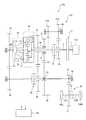
以下、本発明に係る無段変速装置の実施形態について、図面を用いて説明する。図1、図4は、本発明の第1実施形態の無段変速装置を説明する図である。この第1実施形態は、FF(Front engine Front drive)車に搭載される無段変速装置に本発明を適用した例を示す。(First embodiment)
Hereinafter, embodiments of a continuously variable transmission according to the present invention will be described with reference to the drawings. 1 and 4 are diagrams illustrating a continuously variable transmission according to a first embodiment of the present invention. The first embodiment shows an example in which the present invention is applied to a continuously variable transmission mounted on a front engine front drive (FF) vehicle.
まず、構成を説明する。図1において、自動車等の車両100には、駆動源としてのエンジン105と、発進デバイス2と、無段変速装置101と、ディファレンシャル装置70と、左右のドライブシャフト107R、107Lと、左右の駆動輪106R、106Lとが搭載されている。 First, the configuration will be described. In FIG. 1, a
車両100は、FF(Front engine Front drive)車として構成されており、エンジン105、無段変速装置101、および左右の駆動輪106R、106Lが車両前部に配置されている。これにより、車両100は、車両前部に配置されたエンジン105によって、車両前部に配置された駆動輪106R、106Lを駆動して走行する。 The
発進デバイス2は、エンジン105のクランク軸1と無段変速装置101の入力軸3との間に設けられている。発進デバイス2は、乾式クラッチまたはトルクコンバータからなり、エンジン105と無段変速装置101との間の動力伝達を断続する。エンジン105の出力は、クランク軸1から発進デバイス2を介して入力軸3に伝達される。 The
ディファレンシャル装置70は、差動機構を収納するディファレンシャルケース72と、ディファレンシャルケース72の外周部に設けられたファイナル従動ギヤ71と、を有している。ディファレンシャルケース72内の差動機構には、左右のドライブシャフト107R、107Lが連結されている。 The
ディファレンシャル装置70は、ファイナル従動ギヤ71によって無段変速装置101からディファレンシャルケース72に伝達された動力を、左右のドライブシャフト107R、107Lを介して、左右の駆動輪106L、106Rに差動回転可能に伝達する。 The
無段変速装置101は、入力軸3を備えており、この入力軸3は、エンジン105から動力が入力される。 The continuously
無段変速装置101は、遊星歯車機構10を備えており、この遊星歯車機構10は、インターナルギヤ12が内周面に形成されたケーシング11と、インターナルギヤ12と噛合うピニオンギヤ13と、ピニオンギヤ13と噛合うサンギヤ14と、ピニオンギヤ13を回転自在に支持し、入力軸3に対して同軸で一体回転するように連結されたキャリア15と、を有する。 The continuously
無段変速装置101は、ケーシング11と同軸で一体回転するように配置されたモードA駆動軸4Aと、サンギヤ14と同軸で一体回転するように配置されたモードB駆動軸4Bと、を備えている。 The continuously
モードA駆動軸4Aは、中空形状に形成されており、内部に入力軸3が挿通している。モードA駆動軸4Aは、入力軸3と同軸で配置されており、ケーシング11のエンジン105側に連結されている。モードB駆動軸4Bは、サンギヤ14の、エンジン105とは反対側に連結されている。 The mode
無段変速装置101は、無段変速機構20を備えており、この無段変速機構20は、ケーシング11に対して同軸で一体回転するように連結された第1ディスク21と、第1ディスク21に対向し、サンギヤ14に対して同軸で一体回転するように連結された第2ディスク22と、第1ディスク21と第2ディスク22との間で動力を伝達する球状のローラ23と、を有する。第2ディスク22は、モードB駆動軸4Bに連結されており、このモードB駆動軸4Bを介してサンギヤ14と一体回転する。ローラ23は、図示しないアクチュエータによってその回転軸の傾斜角度が変更される。なお、第1ディスク21と第2ディスク22とは同方向に回転する。 The continuously
このように構成された無段変速機構20は、ローラ23の回転軸の傾斜角度を変化させることによって、入力側ディスクの回転数に対する出力側ディスクの回転数の比、すなわち変速比を変化させて、第1ディスク21の回転に対して第2ディスク22の回転が減速する状態から、第1ディスク21の回転に対して第2ディスク22の回転が増速する状態に無段階に変速する。すなわち、無段変速機構20は、トロイダル型無段変速機構として構成されている。 The continuously
無段変速装置101は、モードA駆動ギヤとしてのモード1駆動ギヤ31およびモード3駆動ギヤ33を備えており、このモード1駆動ギヤ31およびモード3駆動ギヤ33は、モードA駆動軸4Aに一体回転するように配置されている。 The continuously
無段変速装置101は、モードB駆動ギヤとしてのモード2駆動ギヤ32を備えており、このモード2駆動ギヤ32は、モードB駆動軸4Bに一体回転するように配置されている。 The continuously
無段変速装置101は、入力軸3と平行に配置されたカウンタ軸40と、入力軸3と平行に配置された後退速軸60と、を備えている。 The continuously
無段変速装置101は、モード1駆動ギヤ31と噛合うモード1従動ギヤ41と、モード2駆動ギヤ32と噛合うモード2従動ギヤ42とを備えている。モード1従動ギヤ41およびモード2従動ギヤ42は、カウンタ軸40に一体回転するように設けられている。 The continuously
無段変速装置101は、モード3駆動ギヤ33と噛合うモード3従動ギヤ43を備えており、このモード3従動ギヤ43は、カウンタ軸40に遊転自在に設けられている。 The continuously
無段変速装置101は、出力ギヤ49を備えており、この出力ギヤ49は、駆動輪106R、106Lに動力を伝達するファイナル従動ギヤ71と噛合っている。出力ギヤ49は、カウンタ軸40に一体回転するように設けられている。 The continuously
無段変速装置101は、後退速駆動ギヤ35を備えており、この後退速駆動ギヤ35は、入力軸3に遊転自在に設けられている。 The continuously
無段変速装置101は、後退速駆動ギヤ35と噛合う後退速第1従動ギヤ61Aと、モード1従動ギヤ41と噛合う後退速第2従動ギヤ61Bとを備えている。後退速第1従動ギヤ61Aおよび後退速第2従動ギヤ61Bは、後退速軸60に一体回転するように設けられている。 The continuously
無段変速装置101は、ワンウェイクラッチ5を備えており、このワンウェイクラッチ5は、車両前進駆動時にモードA駆動軸4Aからカウンタ軸40への動力伝達を許容し、前進被駆動時にカウンタ軸40からモードA駆動軸4Aへの動力伝達を許容しない。ワンウェイクラッチ5は、モード1駆動ギヤ31とモードA駆動軸4Aの間に設けられている。このワンウェイクラッチ5が設けられたことにより、モード1駆動ギヤ31は、車両前進駆動時にモードA駆動軸4Aに一体回転する。なお、ワンウェイクラッチ5は、図3に示すように、モード1従動ギヤ41とカウンタ軸40の間に設けられていてもよい。 The continuously
無段変速装置101は、第1切替機構S1を備えており、この第1切替機構S1は、入力軸3をキャリア15または後退速駆動ギヤ35の一方に連結する連結状態と、入力軸3をキャリア15または後退速駆動ギヤ35の何れにも連結しない中立状態と、に切替える。第1切替機構S1は、入力軸3に設けられている。 The continuously
入力軸3をキャリア15に連結する連結状態のことを、以下、前進連結状態という。また、入力軸3を後退速駆動ギヤ35に連結する連結状態のことを、以下、後退連結状態という。 Hereinafter, the connection state in which the input shaft 3 is connected to the
無段変速装置101は、第2切替機構S2を備えており、この第2切替機構S2は、カウンタ軸40をモード2従動ギヤ42またはモード3従動ギヤ43の一方に連結する連結状態と、カウンタ軸40をモード2従動ギヤ42またはモード3従動ギヤ43の何れにも連結しない中立状態と、に切替える。第2切替機構S2は、カウンタ軸40に設けられている。第2切替機構S2は、ドグクラッチからなる。 The continuously
カウンタ軸40をモード2従動ギヤ42に連結する連結状態を、以下、モード2連結状態という。また、カウンタ軸40をモード3従動ギヤ43に連結する連結状態を、以下、モード3連結状態という。 Hereinafter, the connection state in which the
無段変速装置101は、第1切替機構S1、第2切替機構S2を作動させることで、モード1従動ギヤ41、モード2従動ギヤ42、モード3従動ギヤ43、後退速駆動ギヤ35の何れかからファイナル従動ギヤ71に動力を取り出す。 The continuously
具体的には、第1切替機構S1、第2切替機構S2をそれぞれ前進連結状態、中立状態にすることで、モード1従動ギヤ41から出力ギヤ49を介してファイナル従動ギヤ71に、モード1での車両前進方向の動力を取り出す。 Specifically, by setting the first switching mechanism S1 and the second switching mechanism S2 to the forward connection state and the neutral state, respectively, the
また、第1切替機構S1、第2切替機構S2をそれぞれ前進連結状態、モード2連結状態にすることで、モード2従動ギヤ42から出力ギヤ49を介してファイナル従動ギヤ71に、モード2での車両前進方向の動力を取り出す。 Further, by setting the first switching mechanism S1 and the second switching mechanism S2 to the forward connection state and the
また、第1切替機構S1、第2切替機構S2をそれぞれ前進連結状態、モード3連結状態にすることで、モード3従動ギヤ43から出力ギヤ49を介してファイナル従動ギヤ71に、モード3での車両前進方向の動力を取り出す。 Further, by setting the first switching mechanism S1 and the second switching mechanism S2 to the forward connection state and the mode 3 connection state, respectively, from the mode 3 driven
また、第1切替機構S1、第2切替機構S2をそれぞれ後退連結状態、中立状態にすることで、後退速駆動ギヤ35から後退速第1従動ギヤ61A、後退速第2従動ギヤ61B、モード1従動ギヤ41を経て、出力ギヤ49を介してファイナル従動ギヤ71に、車両後退方向の動力を取り出す。 Further, by setting the first switching mechanism S1 and the second switching mechanism S2 to the reversely connected state and the neutral state, respectively, the reverse speed first driven
このように構成された無段変速装置101において、エンジン105から発進デバイス2を介して入力軸3に伝達された動力は、入力軸3と同軸上に配置された遊星歯車機構10のキャリア15に伝達され、キャリア15を回転させる。 In the continuously
キャリア15が回転すると、キャリア15に支持されたピニオンギヤ13からインターナルギヤ12とサンギヤ14に動力が分割して伝達される。インターナルギヤ12に伝達された動力は、ケーシング11を介して無段変速機構20の第1ディスク21に伝達される。サンギヤ14に伝達された動力は、モードB駆動軸4Bを介して無段変速機構20の第2ディスク22に伝達される。すなわち、遊星歯車機構10において、インターナルギヤ12側とサンギヤ14側とに動力が分割される(パワースプリットが行われる)。 When the
この動力分割(パワースプリット)が行われることで、第1ディスク21およびケーシング11と一体回転するモードA駆動軸4Aを経て駆動輪106R、106Lに伝達される動力伝達経路(モードA動力伝達経路)と、第2ディスク22と一体回転するモードB駆動軸4Bを経て駆動輪106R、106Lに伝達される動力伝達経路(モードB動力伝達経路)とが形成される。 By performing this power split (power split), a power transmission path (mode A power transmission path) is transmitted to the
モードA動力伝達経路を用いて変速を行う場合、サンギヤ14から第2ディスク22に伝達された動力は、第1ディスク21およびケーシング11を介してモードA駆動軸4Aに合流する。また、モードB動力伝達経路を用いて変速を行う場合、インターナルギヤ12からケーシング11および第1ディスク21に伝達された動力は、第2ディスク22を介してモードB駆動軸4Bに合流する。 When shifting is performed using the mode A power transmission path, the power transmitted from the
このように、無段変速装置101は、モードA動力伝達経路を用いて変速を行う無段変速装置(モードA無段変速装置)と、モードB動力伝達経路を用いて変速を行う無段変速装置(モードB無段変速装置)と、を有するように構成されている。 Thus, the continuously
この動力分割(パワースプリット)型の無段変速装置101では、入力軸3の回転数が一定で無段変速機構20の変速比が変化した場合、サンギヤ14の回転数が増加するとインターナルギヤ12の回転数が減少し、サンギヤ14の回転数が減少するとインターナルギヤ12の回転数が増加する。 In this power split type continuously
また、無段変速装置101は、モード1からモード3の3つの走行モードを備えている。モード1では、モード1駆動ギヤ31とモード1従動ギヤ41の噛み合いにより変速を行い、モード2では、モード2駆動ギヤ32とモード2従動ギヤ42の噛み合いにより変速を行い、モード3では、モード3駆動ギヤ33とモード3従動ギヤ43の噛み合いにより変速を行う。 The continuously
これらの、走行モードは、モード1の変速比が最も大きく、モード2、モード3の順に変速比が小さくなるように、各駆動ギヤと各従動ギヤのギヤ比が設定されている。言い換えると、モード1からモード3の走行モードは、ギヤ対を切替えて段階的に変速比を変更する自動変速装置(ステップAT)における変速段に類似する。 In these travel modes, the gear ratio of each drive gear and each driven gear is set so that the gear ratio of
また、この無段変速装置101では、車両前進時は、走行モードをモード1からモード3の間で切替えるとともに、各走行モードで無段変速機構20の変速比を変更することで、無段変速装置101の全体としての変速比を変更する。 In the continuously
本実施形態では、奇数の走行モード、すなわちモード1とモード3は、モードA駆動軸4Aから駆動輪106R、106Lに動力を伝達するモードA動力伝達経路を用いて形成される。また、偶数の走行モード、すなわちモード2は、モードB駆動軸4Bから駆動輪106R、106Lに動力を伝達するモードB動力伝達経路を用いて形成される。 In the present embodiment, an odd number of driving modes, that is,
ここで、モード1からモード3における各駆動ギヤと従動ギヤのギヤ比について説明する。前述したように、無段変速装置101では、入力軸3の回転数が一定で無段変速機構20の変速比が変化した場合、サンギヤ14の回転数が増加するとインターナルギヤ12の回転数が減少し、サンギヤ14の回転数が減少するとインターナルギヤ12の回転数が増加する。以下の説明では、インターナルギヤ12とサンギヤ14の速度比がr2とr1の間で変化するものとする。 Here, the gear ratio of each drive gear and driven gear in
本実施形態では、速度比がr2のときにモード1従動ギヤ41とモード2従動ギヤ42の回転数が一致(同期)するように、モード2のギヤ比(モード2駆動ギヤ32とモード2従動ギヤ42のギヤ比)が設定されている。また、速度比がr1のときにモード2従動ギヤ42とモード3従動ギヤ43の回転数が一致(同期)するように、モード3のギヤ比(モード3駆動ギヤ33とモード3従動ギヤ43のギヤ比)が設定されている。 In the present embodiment, when the speed ratio is r2, the
また、本実施形態では、遊星歯車機構10がシングルピニオン型の遊星歯車機構であるため、奇数の走行モードであるモード1を、モードA動力伝達経路(モードA動力伝達装置)を用いて形成することで、大きな動力伝達を要する車両の発進時において、無段変速機構20の動力伝達効率を最大にでき、かつ、無段変速装置101への入力負荷を最少にできる。 Further, in the present embodiment, since the
上述のように構成された無段変速装置101は、コントロールユニット120に電気的に接続されており、このコントロールユニット120によって制御される。 The continuously
図4において、コントロールユニット120は、CPU、RAM、ROM、入出力インターフェース等を備える図示しないマイクロコンピュータを含んで構成されている。 In FIG. 4, the
コントロールユニット120において、CPUは、RAMの一時記憶機能を利用するとともにROMに予め記憶されたプログラムに従って信号処理を行うようになっている。ROMには、各種制御定数や各種マップ等が予め記憶されている。 In the
コントロールユニット120の入力側には、車両100に設けられたエンジン回転数センサ121、車速センサ122、モードA駆動軸回転数センサ123A、モードB駆動軸回転数センサ123B、出力回転数センサ124、スロットル開度センサ125、無段変速位置センサ126、油温センサ127が接続されている。 On the input side of the
エンジン回転数センサ121は、エンジン105のエンジン回転数、すなわちクランク軸1の回転数を検出し、検出信号をコントロールユニット120に出力する。 The
車速センサ122は、車両100の車速を検出し、検出信号をコントロールユニット120に出力する。車速センサ122は、例えば、駆動輪106R、106Lの回転数を検出し、この回転数に基づいて車速を検出する。 The
モードA駆動軸回転数センサ123Aは、モードA駆動軸の回転数を検出し、検出信号をコントロールユニットに出力する。また、モードB駆動軸回転数センサ123Bは、モードB駆動軸の回転数を検出し、検出信号をコントロールユニット120に出力する。出力回転数センサ124は、出力ギヤ49の回転数を出力回転数として検出し、検出信号をコントロールユニット120に出力する。 The mode A drive shaft
スロットル開度センサ125は、図示しないスロットルバルブのスロットル開度を検出し、検出信号をコントロールユニット120に出力する。 The
無段変速位置センサ126は、無段変速機構20のローラ23の傾斜角度を無段変速位置として検出し、検出信号をコントロールユニット120に出力する。 The continuously variable
油温センサ127は、無段変速機構20の潤滑油の油温を検出し、検出信号をコントロールユニット120に出力する。 The
セレクトデバイスポジションセンサ128は、ドライバーが選択したドライブモードをセンサで検出し、コントロールユニット120に出力する。一方、コントロールユニット120の出力側には、車両100に設けられた無段変速制御装置129、第1切替機構S1、第2切替機構S2が電気的に接続されている。 The select
無段変速制御装置129は、無段変速機構20を油圧で制御するバルブボディからなる。無段変速制御装置129は、コントロールユニット120により電気的に制御される図示しないソレノイドバルブと油圧経路を備えており、ソレノイドバルブにより油圧経路を切替えることで、無段変速機構20の変速比等を変更する。 The continuously variable
コントロールユニット120は、エンジン回転数、車速、モードA駆動軸回転数センサ123A、モードB駆動軸回転数センサ123B、セレクトデバイスポジション、出力回転数、スロットル開度、無段変速位置、油温に基づいて、無段変速制御装置129、第1切替機構S1、第2切替機構S2を制御することで、走行モードをモード1からモード3および後退モードの間で切替を行うとともに、各走行モードで無段変速機構20の変速比を変更し、無段変速装置101の全体としての変速比を変更する。 The
次に、無段変速装置101の動作について、車両の前進走行時と後退走行時に分けて説明する。 Next, the operation of the continuously
(前進走行時の動作)
車両が前進する前進走行時において、車両が停止状態から発進するときは、無段変速装置101はモード1が選択されて、無段変速機構20が最大減速状態となる。(Operation during forward travel)
When the vehicle starts moving forward, when the vehicle starts from a stopped state,
車両の発進後は、モード1において無段変速機構20が最大減速状態から最大増速状態まで変化することで、車速が増加する。 After the vehicle is started, the continuously
無段変速機構20が最大増速状態まで変化した後、モード2に切替えられる。その後、モード2において無段変速機構20が最大増速状態から最大減速状態まで変化することで、車速が更に増加する。以降、モード3においても同様に動作する。 After the continuously
ここで、走行モードを切替えるときの具体的な動作について、モード1からモード2に切替を行う場合を例にして説明する。 Here, a specific operation when switching the travel mode will be described by taking as an example the case of switching from
走行モードをモード1からモード2に切替える際は、遊星歯車機構10の速度比がr2となってモード1従動ギヤ41とモード2従動ギヤ42の回転数が同期する直前の状態で、コントロールユニット120が、第1切替機構S1を前進連結状態に維持したまま、第2切替機構S2を中立状態からモード2連結状態にする。 When the traveling mode is switched from
これにより、モード2従動ギヤ42の回転数がモード1従動ギヤ41の回転数より僅かに速い状態で第2切替機構S2がモード2連結状態に切替えられるため、ワンウェイクラッチ5が解放され、動力伝達経路がモード1従動ギヤ41からモード2従動ギヤ42に切替えられる。このとき、モード2従動ギヤ42とモード1従動ギヤ41の差回転が少ないため、変速ショックを小さくできるとともに、動力伝達が途切れるのを防止できる。 As a result, the second switching mechanism S2 is switched to the
走行モードをモード2からモード3に切替える際は、遊星歯車機構10の速度比がr1となってモード2従動ギヤ42とモード3従動ギヤ43の回転数が同期する直前または直後の状態で、コントロールユニット120が、第1切替機構S1を前進連結状態に維持したまま、第2切替機構S2をモード2連結状態から中立状態を経てモード3連結状態にする。 When the travel mode is switched from
これにより、モード2従動ギヤ42とモード2従動ギヤ43の差回転が少ない状態で切替が行われるため、変速ショックを小さくできるとともに、変速時間を短くできる。 As a result, switching is performed in a state where the differential rotation between the
また、モード2からのモード3への切替の際は、第2切替機構S2が中立状態を経るため、第2切替機構S2の二重係合を防止できる。このため、モード2従動ギヤ42に動力を伝達するモードB駆動軸4B(モードB動力伝達装置)と、モード3従動ギヤ43に動力を伝達するモードA駆動軸4A(モードA動力伝達装置)とが、第2切替機構S2の切替の際にロックすることを防止できる。 Further, when the
(後退走行時の動作)
車両が後退する後退走行時は、第1切替機構S1により、後退速駆動ギヤ35が入力軸3に締結される。また、第2切替機構S2が中立状態にされる。(Operation during reverse running)
During reverse travel in which the vehicle moves backward, the reverse
この状態では、入力軸3の動力は、後退速第1従動ギヤ61A、後退速第2従動ギヤ61B、モード1従動ギヤ41、出力ギヤ49を経てファイナル従動ギヤ71に伝達される。 In this state, the power of the input shaft 3 is transmitted to the final driven
このとき、ワンウェイクラッチ5が接続していることで、モード1駆動ギヤ31とモード3駆動ギヤ33が連れ回されるが、第1切替機構S1は後退速状態であり、第2切替機構S2は中立状態であるため、支障ない。 At this time, since the one-
なお、動力分割(パワースプリット)型の無段変速装置101では、前進の全ての走行モードにおいて、動力がサンギヤ14側とインターナルギヤ12側に分割されるため、遊星歯車機構10を通過する動力または無段変速機構20を通過する動力は、エンジン105から入力軸3に入力された動力より小さくなる。このため、全ての走行モードにおいて、無段変速装置101の全体の動力伝達効率は、遊星歯車機構10の動力伝達効率と無段変速機構20の動力伝達効率の中間となり、高い動力伝達効率にすることができる。 In the power split type continuously
このように本実施形態の無段変速装置101によれば、第1の効果として、インターナルギヤ12側のモードA無段変速装置と、サンギヤ14側のモードB無段変速装置を構成できる。そして、モードA無段変速装置側に奇数の走行モードであるモード1とモード3を配置し、モードB無段変速装置側に偶数の走行モードであるモード2を配置し、これらのモードを切替えることにより、1つの遊星歯車機構10のみでモードAとモードBの2タイプの無段変速装置を使い分けることができ、パワースプリットモードを多段化できる。 Thus, according to the continuously
また、第2の効果として、モードAとモードBをさらに多段化することにより、無段変速装置101の変速比幅を広げることができ、全速度域で燃費を向上でき、変速品質を向上できる。 Further, as a second effect, by further increasing the number of stages of mode A and mode B, the speed ratio range of the continuously
また、第3の効果として、遊星歯車機構10と無段変速機構20で動力を分担するため、遊星歯車機構10と無段変速機構20のそれぞれの大きさを小型化でき、耐久性を向上でき、機械的損失を低減できる。 As a third effect, since the
この結果、機械的損失を低減できるとともに、燃費向上効果を十分に得ることができる。 As a result, the mechanical loss can be reduced and the fuel efficiency improvement effect can be sufficiently obtained.
また、第1から第3の効果に加えて、カウンタ軸40を1つのみ備えるため、2つのカウンタ軸を備える場合よりも無段変速装置101を径方向に小型化できる。 In addition to the first to third effects, since only one
また、後退速第1従動ギヤ61Aおよび後退速第2従動ギヤ61Bを後退速軸60に独立して配置したことで、これらのギヤをカウンタ軸40に配置した場合よりもカウンタ軸40を軸方向に短縮できるため、無段変速装置101を小型化できる。 In addition, since the reverse speed first driven
また、後退速第1従動ギヤ61Aおよび後退速第2従動ギヤ61Bを後退速軸60に独立して配置したことで、これらのギヤをカウンタ軸40に配置した場合よりもカウンタ軸40の慣性重量を低減できるため、モードの切替速度、すなわち変速速度を速くすることができる。 Further, since the reverse speed first driven
また、本実施形態の無段変速装置101によれば、第2切替機構S2がドグクラッチからなるため、機械的損失をさらに低減できる。 Moreover, according to the continuously
(第2実施形態)
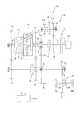
第2実施形態の無段変速装置について説明する。なお、第1実施形態の無段変速装置101と同様の構成部材には第1実施形態と同じ符号を付して説明を省略する。(Second Embodiment)
A continuously variable transmission according to a second embodiment will be described. In addition, the same code | symbol as 1st Embodiment is attached | subjected to the component similar to the continuously
図2において、車両100は、第1実施形態の無段変速装置101に代えて無段変速装置102を備えている。 In FIG. 2, the
無段変速装置102において、後退速駆動ギヤ35は、入力軸3に一体回転するように設けられている。 In the continuously
また、後退速駆動ギヤ35と噛合う後退速第1従動ギヤ61Aが、後退速軸60に一体回転するように設けられている。 A reverse speed first driven gear 61 </ b> A that meshes with the reverse
また、モード1従動ギヤ41と噛合う後退速第2従動ギヤ61Bが、後退速軸60に遊転自在に設けられている。 A reverse speed second driven
無段変速装置102は、第1切替機構S1を備えており、この第1切替機構S1は、入力軸3をキャリア15に連結する連結状態と、入力軸3をキャリア15に連結しない解放状態と、に切替える。第1切替機構S1は、入力軸3に設けられている。 The continuously
無段変速装置102は、第2切替機構S2を備えており、この第2切替機構S2は、カウンタ軸40をモード2従動ギヤ42またはモード3従動ギヤ43の一方に連結する連結状態と、カウンタ軸40をモード2従動ギヤ42またはモード3従動ギヤ43の何れにも連結しない中立状態と、に切替える。第2切替機構S2は、カウンタ軸40に設けられている。第2切替機構S2は、ドグクラッチからなる。 The continuously
無段変速装置102は、第3切替機構S3を備えており、この第3切替機構S3は、後退速軸60を後退速第2従動ギヤ61Bに連結する連結状態と、後退速軸60を後退速第2従動ギヤ61Bに連結しない解放状態と、に切替える。第3切替機構S3は、後退速軸60に設けられている。 The continuously
本実施形態では、無段変速装置102は、第1切替機構S1、第2切替機構S2、第3切替機構S3をそれぞれ連結状態、中立状態、解放状態にすることで、モード1従動ギヤ41から出力ギヤ49を介してファイナル従動ギヤ71に、モード1での車両前進方向の動力を取り出す。 In the present embodiment, the continuously
また、第1切替機構S1、第2切替機構S2、第3切替機構S3をそれぞれ連結状態、モード2連結状態、解放状態にすることで、モード2従動ギヤ42から出力ギヤ49を介してファイナル従動ギヤ71に、モード2での車両前進方向の動力を取り出す。 In addition, the first driven mechanism S1, the second switched mechanism S2, and the third switched mechanism S3 are connected to the connected state, the
また、第1切替機構S1、第2切替機構S2、第3切替機構S3をそれぞれ連結状態、モード3連結状態、解放状態にすることで、モード3従動ギヤ43から出力ギヤ49を介してファイナル従動ギヤ71に、モード3での車両前進方向の動力を取り出す。 In addition, the first driven mechanism S1, the second switched mechanism S2, and the third switched mechanism S3 are connected to the connected state, the mode 3 connected state, and the released state, respectively, so that the final driven from the mode 3 driven
また、第1切替機構S1、第2切替機構S2、第3切替機構S3をそれぞれ解放状態、中立状態、連結状態にすることで、後退速駆動ギヤ35から後退速第1従動ギヤ61A、後退速第2従動ギヤ61B、モード1従動ギヤ41を経て、出力ギヤ49を介してファイナル従動ギヤ71に、車両後退方向の動力を取り出す。 Further, the first switching mechanism S1, the second switching mechanism S2, and the third switching mechanism S3 are set in a released state, a neutral state, and a connected state, respectively, so that the reverse speed first driven
なお、本実施形態では、図2のコントロールユニット120は、第1切替機構S1および第2切替機構S2に加えて、第3切替機構S3も制御する。 In the present embodiment, the
このように本実施形態の無段変速装置102によれば、第1実施形態と同様に第1から第3の効果を奏することができる。この結果、機械的損失を低減できるとともに、燃費向上効果を十分に得ることができる。 Thus, according to the continuously
また、カウンタ軸40を1つのみ備えるため、カウンタ軸40を2つ備える場合よりも無段変速装置102を径方向に小型化できる。 Further, since only one
また、本実施形態の無段変速装置102によれば、第2切替機構S2がドグクラッチからなるため、機械的損失をさらに低減できる。 In addition, according to the continuously
(第3実施形態)
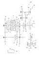
第3実施形態の無段変速装置について説明する。なお、第1実施形態の無段変速装置101と同様の構成部材には第1実施形態と同じ符号を付して説明を省略する。(Third embodiment)
A continuously variable transmission according to a third embodiment will be described. In addition, the same code | symbol as 1st Embodiment is attached | subjected to the component similar to the continuously
図3において、車両100は、第1実施形態の無段変速装置101に代えて無段変速装置103を備えている。 In FIG. 3, the
無段変速装置103は、入力軸3と平行に配置された後退速軸60と、入力軸3と平行に配置された後退速アイドラ軸90と、を備えている。 The continuously
無段変速装置103は、後退速駆動ギヤ35を備えており、この後退速駆動ギヤ35は、入力軸3に遊転自在に設けられている。 The continuously
無段変速装置103は、後退速駆動ギヤ35と噛合う後退速第1従動ギヤ61Aと、後退速第2従動ギヤ61Bとを備えている。後退速第1従動ギヤ61Aおよび後退速第2従動ギヤ61Bは、後退速軸60に一体回転するように設けられている。 The continuously
無段変速装置103は、後退速第2従動ギヤ61Bと噛合う後退速第1アイドラギヤ92Aと、ファイナル従動ギヤ71と噛合う後退速第2アイドラギヤ92Bとを備えている。後退速第1アイドラギヤ92Aおよび後退速第2アイドラギヤ92Bは、後退速アイドラ軸90に一体回転するように設けられている。 The continuously
後退速第1従動ギヤ61A、後退速第2従動ギヤ61B、後退速第1アイドラギヤ92Aおよび後退速第2アイドラギヤ92Bは、カウンタ軸40よりも上方に配置されている。また、カウンタ軸40の下方には、オイルが貯留されている。このため、後退速第1従動ギヤ61A、後退速第2従動ギヤ61B、後退速第1アイドラギヤ92Aおよび後退速第2アイドラギヤ92Bは、オイルを掻き上げることがない。したがって、オイルの撹拌抵抗を低減でき、燃費を向上できる。 The reverse speed first driven
無段変速装置103は、第1切替機構S1を備えており、この第1切替機構S1は、入力軸3をキャリア15または後退速駆動ギヤ35の一方に連結する連結状態と、入力軸3をキャリア15または後退速駆動ギヤ35の何れにも連結しない中立状態と、に切替える。第1切替機構S1は、入力軸3に設けられている。 The continuously
入力軸3をキャリア15に連結する連結状態のことを、以下、前進連結状態という。また、入力軸3を後退速駆動ギヤ35に連結する連結状態のことを、以下、後退連結状態という。 Hereinafter, the connection state in which the input shaft 3 is connected to the
無段変速装置103は、第2切替機構S2を備えており、この第2切替機構S2は、カウンタ軸40をモード2従動ギヤ42またはモード3従動ギヤ43の一方に連結する連結状態と、カウンタ軸40をモード2従動ギヤ42またはモード3従動ギヤ43の何れにも連結しない中立状態と、に切替える。第2切替機構S2は、カウンタ軸40に設けられている。第2切替機構S2は、ドグクラッチからなる。 The continuously
カウンタ軸40をモード2従動ギヤ42に連結する連結状態を、以下、モード2連結状態という。また、カウンタ軸40をモード3従動ギヤ43に連結する連結状態を、以下、モード3連結状態という。 Hereinafter, the connection state in which the
本実施形態では、無段変速装置103は、第1切替機構S1、第2切替機構S2をそれぞれ前進連結状態、中立状態にすることで、モード1従動ギヤ41から出力ギヤ49を介してファイナル従動ギヤ71に、モード1での車両前進方向の動力を取り出す。 In the present embodiment, the continuously
また、第1切替機構S1、第2切替機構S2をそれぞれ前進連結状態、モード2連結状態にすることで、モード2従動ギヤ42から出力ギヤ49を介してファイナル従動ギヤ71に、モード2での車両前進方向の動力を取り出す。 Further, by setting the first switching mechanism S1 and the second switching mechanism S2 to the forward connection state and the
また、第1切替機構S1、第2切替機構S2をそれぞれ前進連結状態、モード3連結状態にすることで、モード3従動ギヤ43から出力ギヤ49を介してファイナル従動ギヤ71に、モード3での車両前進方向の動力を取り出す。 Further, by setting the first switching mechanism S1 and the second switching mechanism S2 to the forward connection state and the mode 3 connection state, respectively, from the mode 3 driven
また、第1切替機構S1、第2切替機構S2をそれぞれ後退連結状態、中立状態にすることで、後退速駆動ギヤ35から後退速第1従動ギヤ61A、後退速第2従動ギヤ61B、後退速第2アイドラギヤ92A、後退速第1アイドラギヤ92Bを経て、出力ギヤ49を介してファイナル従動ギヤ71に、車両後退方向の動力を取り出す。 Further, by setting the first switching mechanism S1 and the second switching mechanism S2 to the reversely connected state and the neutral state, respectively, the reverse
このように本実施形態の無段変速装置103によれば、第1実施形態と同様に第1から第3の効果を奏することができる。この結果、機械的損失を低減できるとともに、燃費向上効果を十分に得ることができる。 As described above, according to the continuously
また、カウンタ軸40を1つのみ備えるため、カウンタ軸40を2つ備える場合よりも無段変速装置102を径方向に小型化できる。 Further, since only one
また、後退速第1従動ギヤ61Aおよび後退速第2従動ギヤ61Bを後退速軸60に独立して配置し、後退速第1アイドラギヤ92Aおよび後退速第2アイドラギヤ92Bを後退速アイドラ軸90に独立して配置し、さらに、これらの4つのギヤをカウンタ軸40に連れ回らないようにしたことで、カウンタ軸40の慣性重量を低減できるため、モードの切替速度、すなわち変速速度を速くすることができる。 Further, the reverse speed first driven
また、本実施形態の無段変速装置103によれば、第2切替機構S2がドグクラッチからなるため、機械的損失をさらに低減できる。 In addition, according to the continuously
3...入力軸、4A...モードA駆動軸、4B...モードB駆動軸、5...ワンウェイクラッチ、10...遊星歯車機構、11...ケーシング、12...インターナルギヤ、13...ピニオンギヤ、14...サンギヤ、15...キャリア、20...無段変速機構、21...第1ディスク、22...第2ディスク、23...ローラ、31...モード1駆動ギヤ(モードA駆動ギヤ)、32...モード2駆動ギヤ(モードB駆動ギヤ)、33...モード3駆動ギヤ(モードA駆動ギヤ)、35...後退速駆動ギヤ、40...カウンタ軸、41...モード1従動ギヤ、42...モード2従動ギヤ、43...モード3従動ギヤ、49...出力ギヤ、60...後退速軸、61A...後退速第1従動ギヤ、61B...後退速第2従動ギヤ、71...ファイナル従動ギヤ、90...後退速アイドラ軸、92A...後退速第1アイドラギヤ、92B...後退速第2アイドラギヤ、101,102,103...無段変速装置、105...エンジン、106L,106R...駆動輪、S1...第1切替機構、S2...第2切替機構、S3...第3切替機構、 3 ... input shaft, 4A ... mode A drive shaft, 4B ... mode B drive shaft, 5 ... one-way clutch, 10 ... planetary gear mechanism, 11 ... casing, 12 ... Internal gear, 13 ... pinion gear, 14 ... sun gear, 15 ... carrier, 20 ... continuously variable transmission mechanism, 21 ... first disc, 22 ... second disc, 23 .. Roller, 31 ...
Claims (4)
Translated fromJapaneseインターナルギヤが内周面に形成されたケーシングと、前記インターナルギヤと噛合うピニオンギヤと、前記ピニオンギヤと噛合うサンギヤと、前記ピニオンギヤを回転自在に支持し、前記入力軸に対して同軸で一体回転するように連結されたキャリアと、を有する遊星歯車機構と、
前記ケーシングと同軸で一体回転するように配置されたモードA駆動軸と、
前記サンギヤと同軸で一体回転するように配置されたモードB駆動軸と、
前記ケーシングに対して同軸で一体回転するように連結された第1ディスクと、前記第1ディスクに対向し、前記サンギヤに対して同軸で一体回転するように連結された第2ディスクと、前記第1ディスクと前記第2ディスクとの間で動力を伝達するローラと、を有する無段変速機構と、
前記モードA駆動軸に一体回転するように配置された少なくとも1つのモードA駆動ギヤと、
前記モードB駆動軸に一体回転するように配置された少なくとも1つのモードB駆動ギヤと、
前記入力軸と平行に配置されたカウンタ軸と、
前記入力軸と平行に配置された後退速軸と、
前記モードA駆動ギヤとしてのモード1駆動ギヤおよびモード3駆動ギヤと、
前記モードB駆動ギヤとしてのモード2駆動ギヤと、を備え、
前記モード1駆動ギヤと噛合うモード1従動ギヤと、前記モード2駆動ギヤと噛合うモード2従動ギヤとが、前記カウンタ軸に一体回転するように設けられ、
前記モード3駆動ギヤと噛合うモード3従動ギヤが、前記カウンタ軸に遊転自在に設けられ、
駆動輪に動力を伝達するファイナル従動ギヤと噛合う出力ギヤが、前記カウンタ軸に一体回転するように設けられ、
後退速駆動ギヤが、前記入力軸に遊転自在に設けられ、
前記後退速駆動ギヤと噛合う後退速第1従動ギヤと、前記モード1従動ギヤと噛合う後退速第2従動ギヤとが、前記後退速軸に一体回転するように設けられ、
車両前進駆動時に前記モードA駆動軸から前記カウンタ軸への動力伝達を許容し、車両前進被駆動時に前記カウンタ軸から前記モードA駆動軸への動力伝達を許容しないワンウェイクラッチが、前記モード1駆動ギヤと前記モードA駆動軸の間、または、前記モード1従動ギヤと前記カウンタ軸の間に設けられ、
前記入力軸を前記キャリアまたは前記後退速駆動ギヤの一方に連結する連結状態と、前記入力軸を前記キャリアまたは前記後退速駆動ギヤの何れにも連結しない中立状態と、に切替える第1切替機構が前記入力軸に設けられ、
前記カウンタ軸を前記モード2従動ギヤまたは前記モード3従動ギヤの一方に連結する連結状態と、前記カウンタ軸を前記モード2従動ギヤまたは前記モード3従動ギヤの何れにも連結しない中立状態と、に切替える第2切替機構が前記カウンタ軸に設けられることを特徴とする無段変速装置。An input shaft to which power is input from a drive source;
A casing in which an internal gear is formed on the inner peripheral surface, a pinion gear that meshes with the internal gear, a sun gear that meshes with the pinion gear, and the pinion gear rotatably supported, and coaxially integrated with the input shaft A planetary gear mechanism having a carrier coupled to rotate;
A mode A drive shaft arranged coaxially and integrally with the casing;
A mode B drive shaft arranged coaxially and integrally with the sun gear;
A first disk connected to the casing coaxially and integrally for rotation; a second disk opposed to the first disk and connected to the sun gear coaxially and integrally for rotation; and the first disk A continuously variable transmission mechanism having a roller for transmitting power between one disk and the second disk;
At least one mode A drive gear arranged to rotate integrally with the mode A drive shaft;
At least one mode B drive gear arranged to rotate integrally with the mode B drive shaft;
A counter shaft arranged parallel to the input shaft;
A reverse speed axis disposed parallel to the input axis;
A mode 1 drive gear and a mode 3 drive gear as the mode A drive gear;
A mode 2 drive gear as the mode B drive gear,
A mode 1 driven gear meshing with the mode 1 drive gear and a mode 2 driven gear meshing with the mode 2 drive gear are provided to rotate integrally with the counter shaft;
A mode 3 driven gear meshing with the mode 3 drive gear is provided on the counter shaft so as to be freely rotatable;
An output gear that meshes with a final driven gear that transmits power to the drive wheels is provided to rotate integrally with the counter shaft,
A reverse drive gear is provided on the input shaft so as to be freely rotatable,
A reverse speed first driven gear meshing with the reverse speed drive gear and a reverse speed second driven gear meshing with the mode 1 driven gear are provided so as to rotate integrally with the reverse speed shaft,
A one-way clutch that allows power transmission from the mode A drive shaft to the counter shaft during vehicle forward drive and does not allow power transmission from the counter shaft to the mode A drive shaft during vehicle forward drive is the mode 1 drive. Provided between the gear and the mode A drive shaft, or between the mode 1 driven gear and the counter shaft,
A first switching mechanism that switches between a connected state in which the input shaft is connected to one of the carrier or the reverse drive gear and a neutral state in which the input shaft is not connected to either the carrier or the reverse drive gear; Provided on the input shaft;
A connected state in which the counter shaft is connected to one of the mode 2 driven gear or the mode 3 driven gear, and a neutral state in which the counter shaft is not connected to either the mode 2 driven gear or the mode 3 driven gear. A continuously variable transmission, wherein a second switching mechanism for switching is provided on the counter shaft.
インターナルギヤが内周面に形成されたケーシングと、前記インターナルギヤと噛合うピニオンギヤと、前記ピニオンギヤと噛合うサンギヤと、前記ピニオンギヤを回転自在に支持し、前記入力軸に対して同軸で一体回転するように連結されたキャリアと、を有する遊星歯車機構と、
前記ケーシングと同軸で一体回転するように配置されたモードA駆動軸と、
前記サンギヤと同軸で一体回転するように配置されたモードB駆動軸と、
前記ケーシングに対して同軸で一体回転するように連結された第1ディスクと、前記第1ディスクに対向し、前記サンギヤに対して同軸で一体回転するように連結された第2ディスクと、前記第1ディスクと前記第2ディスクとの間で動力を伝達するローラと、を有する無段変速機構と、
前記モードA駆動軸に一体回転するように配置された少なくとも1つのモードA駆動ギヤと、
前記モードB駆動軸に一体回転するように配置された少なくとも1つのモードB駆動ギヤと、
前記入力軸と平行に配置されたカウンタ軸と、
前記入力軸と平行に配置された後退速軸と、
前記モードA駆動ギヤとしてのモード1駆動ギヤおよびモード3駆動ギヤと、
前記モードB駆動ギヤとしてのモード2駆動ギヤと、を備え、
前記モード1駆動ギヤと噛合うモード1従動ギヤと、前記モード2駆動ギヤと噛合うモード2従動ギヤとが、前記カウンタ軸に一体回転するように設けられ、
前記モード3駆動ギヤと噛合うモード3従動ギヤが、前記カウンタ軸に遊転自在に設けられ、
駆動輪に動力を伝達するファイナル従動ギヤと噛合う出力ギヤが、前記カウンタ軸に一体回転するように設けられ、
後退速駆動ギヤが、前記入力軸に一体回転するように設けられ、
前記後退速駆動ギヤと噛合う後退速第1従動ギヤが、前記後退速軸に一体回転するように設けられ、
前記モード1従動ギヤと噛合う後退速第2従動ギヤが、前記後退速軸に遊転自在に設けられ、
車両前進駆動時に前記モードA駆動軸から前記カウンタ軸への動力伝達を許容し、車両前進被駆動時に前記カウンタ軸から前記モードA駆動軸への動力伝達を許容しないワンウェイクラッチが、前記モード1駆動ギヤと前記モードA駆動軸の間、または、前記モード1従動ギヤと前記カウンタ軸の間に設けられ、
前記入力軸を前記キャリアに連結する連結状態と、前記入力軸を前記キャリアに連結しない解放状態と、に切替える第1切替機構が前記入力軸に設けられ、
前記カウンタ軸を前記モード2従動ギヤまたは前記モード3従動ギヤの一方に連結する連結状態と、前記カウンタ軸を前記モード2従動ギヤまたは前記モード3従動ギヤの何れにも連結しない中立状態と、に切替える第2切替機構が前記カウンタ軸に設けられ、
前記後退速軸を前記後退速第2従動ギヤに連結する連結状態と、前記後退速軸を前記後退速第2従動ギヤに連結しない解放状態と、に切替える第3切替機構が前記後退速軸に設けられることを特徴とする無段変速装置。An input shaft to which power is input from a drive source;
A casing in which an internal gear is formed on the inner peripheral surface, a pinion gear that meshes with the internal gear, a sun gear that meshes with the pinion gear, and the pinion gear rotatably supported, and coaxially integrated with the input shaft A planetary gear mechanism having a carrier coupled to rotate;
A mode A drive shaft arranged coaxially and integrally with the casing;
A mode B drive shaft arranged coaxially and integrally with the sun gear;
A first disk connected to the casing coaxially and integrally for rotation; a second disk opposed to the first disk and connected to the sun gear coaxially and integrally for rotation; and the first disk A continuously variable transmission mechanism having a roller for transmitting power between one disk and the second disk;
At least one mode A drive gear arranged to rotate integrally with the mode A drive shaft;
At least one mode B drive gear arranged to rotate integrally with the mode B drive shaft;
A counter shaft arranged parallel to the input shaft;
A reverse speed axis disposed parallel to the input axis;
A mode 1 drive gear and a mode 3 drive gear as the mode A drive gear;
A mode 2 drive gear as the mode B drive gear,
A mode 1 driven gear meshing with the mode 1 drive gear and a mode 2 driven gear meshing with the mode 2 drive gear are provided to rotate integrally with the counter shaft;
A mode 3 driven gear meshing with the mode 3 drive gear is provided on the counter shaft so as to be freely rotatable;
An output gear that meshes with a final driven gear that transmits power to the drive wheels is provided to rotate integrally with the counter shaft,
A reverse speed drive gear is provided to rotate integrally with the input shaft,
A reverse speed first driven gear meshing with the reverse speed drive gear is provided to rotate integrally with the reverse speed shaft;
A reverse speed second driven gear meshing with the mode 1 driven gear is provided on the reverse speed shaft so as to be freely rotatable,
A one-way clutch that allows power transmission from the mode A drive shaft to the counter shaft during vehicle forward drive and does not allow power transmission from the counter shaft to the mode A drive shaft during vehicle forward drive is the mode 1 drive. Provided between the gear and the mode A drive shaft, or between the mode 1 driven gear and the counter shaft,
A first switching mechanism for switching between a connected state in which the input shaft is connected to the carrier and a released state in which the input shaft is not connected to the carrier;
A connected state in which the counter shaft is connected to one of the mode 2 driven gear or the mode 3 driven gear, and a neutral state in which the counter shaft is not connected to either the mode 2 driven gear or the mode 3 driven gear. A second switching mechanism for switching is provided on the counter shaft;
A third switching mechanism that switches between a connected state in which the reverse speed shaft is connected to the reverse speed second driven gear and a released state in which the reverse speed shaft is not connected to the reverse speed second driven gear is provided on the reverse speed shaft. A continuously variable transmission characterized by being provided.
インターナルギヤが内周面に形成されたケーシングと、前記インターナルギヤと噛合うピニオンギヤと、前記ピニオンギヤと噛合うサンギヤと、前記ピニオンギヤを回転自在に支持し、前記入力軸に対して同軸で一体回転するように連結されたキャリアと、を有する遊星歯車機構と、
前記ケーシングと同軸で一体回転するように配置されたモードA駆動軸と、
前記サンギヤと同軸で一体回転するように配置されたモードB駆動軸と、
前記ケーシングに対して同軸で一体回転するように連結された第1ディスクと、前記第1ディスクに対向し、前記サンギヤに対して同軸で一体回転するように連結された第2ディスクと、前記第1ディスクと前記第2ディスクとの間で動力を伝達するローラと、を有する無段変速機構と、
前記モードA駆動軸に一体回転するように配置された少なくとも1つのモードA駆動ギヤと、
前記モードB駆動軸に一体回転するように配置された少なくとも1つのモードB駆動ギヤと、
前記入力軸と平行に配置されたカウンタ軸と、
前記入力軸と平行に配置された後退速軸と、
前記入力軸と平行に配置された後退速アイドラ軸と、
前記モードA駆動ギヤとしてのモード1駆動ギヤおよびモード3駆動ギヤと、
前記モードB駆動ギヤとしてのモード2駆動ギヤと、を備え、
前記モード1駆動ギヤと噛合うモード1従動ギヤと、前記モード2駆動ギヤと噛合うモード2従動ギヤとが、前記カウンタ軸に一体回転するように設けられ、
前記モード3駆動ギヤと噛合うモード3従動ギヤが、前記カウンタ軸に遊転自在に設けられ、
駆動輪に動力を伝達するファイナル従動ギヤと噛合う出力ギヤが、前記カウンタ軸に一体回転するように設けられ、
後退速駆動ギヤが、前記入力軸に遊転自在に設けられ、
前記後退速駆動ギヤと噛合う後退速第1従動ギヤと、後退速第2従動ギヤとが、前記後退速軸に一体回転するように設けられ、
前記後退速第2従動ギヤと噛合う後退速第1アイドラギヤと、前記ファイナル従動ギヤと噛合う後退速第2アイドラギヤとが、前記後退速アイドラ軸に一体回転するように設けられ、
車両前進駆動時に前記モードA駆動軸から前記カウンタ軸への動力伝達を許容し、車両前進被駆動時に前記カウンタ軸から前記モードA駆動軸への動力伝達を許容しないワンウェイクラッチが、前記モード1駆動ギヤと前記モードA駆動軸の間、または、前記モード1従動ギヤと前記カウンタ軸の間に設けられ、
前記入力軸を前記キャリアまたは前記後退速駆動ギヤの一方に連結する連結状態と、前記入力軸を前記キャリアまたは前記後退速駆動ギヤの何れにも連結しない中立状態と、に切替える第1切替機構が前記入力軸に設けられ、
前記カウンタ軸を前記モード2従動ギヤまたは前記モード3従動ギヤの一方に連結する連結状態と、前記カウンタ軸を前記モード2従動ギヤまたは前記モード3従動ギヤの何れにも連結しない中立状態と、に切替える第2切替機構が前記カウンタ軸に設けられることを特徴とする無段変速装置。An input shaft to which power is input from a drive source;
A casing in which an internal gear is formed on the inner peripheral surface, a pinion gear that meshes with the internal gear, a sun gear that meshes with the pinion gear, and the pinion gear rotatably supported, and coaxially integrated with the input shaft A planetary gear mechanism having a carrier coupled to rotate;
A mode A drive shaft arranged coaxially and integrally with the casing;
A mode B drive shaft arranged coaxially and integrally with the sun gear;
A first disk connected to the casing coaxially and integrally for rotation; a second disk opposed to the first disk and connected to the sun gear coaxially and integrally for rotation; and the first disk A continuously variable transmission mechanism having a roller for transmitting power between one disk and the second disk;
At least one mode A drive gear arranged to rotate integrally with the mode A drive shaft;
At least one mode B drive gear arranged to rotate integrally with the mode B drive shaft;
A counter shaft arranged parallel to the input shaft;
A reverse speed axis disposed parallel to the input axis;
A reverse idler shaft disposed parallel to the input shaft;
A mode 1 drive gear and a mode 3 drive gear as the mode A drive gear;
A mode 2 drive gear as the mode B drive gear,
A mode 1 driven gear meshing with the mode 1 drive gear and a mode 2 driven gear meshing with the mode 2 drive gear are provided to rotate integrally with the counter shaft;
A mode 3 driven gear meshing with the mode 3 drive gear is provided on the counter shaft so as to be freely rotatable;
An output gear that meshes with a final driven gear that transmits power to the drive wheels is provided to rotate integrally with the counter shaft,
A reverse drive gear is provided on the input shaft so as to be freely rotatable,
A reverse speed first driven gear meshing with the reverse speed drive gear and a reverse speed second driven gear are provided to rotate integrally with the reverse speed shaft;
A reverse speed first idler gear meshing with the reverse speed second driven gear and a reverse speed second idler gear meshing with the final driven gear are provided to rotate integrally with the reverse speed idler shaft;
A one-way clutch that allows power transmission from the mode A drive shaft to the counter shaft during vehicle forward drive and does not allow power transmission from the counter shaft to the mode A drive shaft during vehicle forward drive is the mode 1 drive. Provided between the gear and the mode A drive shaft, or between the mode 1 driven gear and the counter shaft,
A first switching mechanism that switches between a connected state in which the input shaft is connected to one of the carrier or the reverse drive gear and a neutral state in which the input shaft is not connected to either the carrier or the reverse drive gear; Provided on the input shaft;
A connected state in which the counter shaft is connected to one of the mode 2 driven gear or the mode 3 driven gear, and a neutral state in which the counter shaft is not connected to either the mode 2 driven gear or the mode 3 driven gear. A continuously variable transmission, wherein a second switching mechanism for switching is provided on the counter shaft.
Priority Applications (3)
| Application Number | Priority Date | Filing Date | Title |
|---|---|---|---|
| JP2016014272AJP6575376B2 (en) | 2016-01-28 | 2016-01-28 | Continuously variable transmission |
| DE102017201027.4ADE102017201027B4 (en) | 2016-01-28 | 2017-01-23 | Continuously variable transmission |
| CN201710060925.9ACN107013636B (en) | 2016-01-28 | 2017-01-25 | Stepless speed change device |
Applications Claiming Priority (1)
| Application Number | Priority Date | Filing Date | Title |
|---|---|---|---|
| JP2016014272AJP6575376B2 (en) | 2016-01-28 | 2016-01-28 | Continuously variable transmission |
Publications (2)
| Publication Number | Publication Date |
|---|---|
| JP2017133603A JP2017133603A (en) | 2017-08-03 |
| JP6575376B2true JP6575376B2 (en) | 2019-09-18 |
Family
ID=59327526
Family Applications (1)
| Application Number | Title | Priority Date | Filing Date |
|---|---|---|---|
| JP2016014272AActiveJP6575376B2 (en) | 2016-01-28 | 2016-01-28 | Continuously variable transmission |
Country Status (3)
| Country | Link |
|---|---|
| JP (1) | JP6575376B2 (en) |
| CN (1) | CN107013636B (en) |
| DE (1) | DE102017201027B4 (en) |
Families Citing this family (1)
| Publication number | Priority date | Publication date | Assignee | Title |
|---|---|---|---|---|
| CN110094470B (en)* | 2019-06-05 | 2023-11-07 | 重庆大学 | Elliptic bevel gear pair-based variable speed device with controllable time-varying transmission ratio |
Family Cites Families (9)
| Publication number | Priority date | Publication date | Assignee | Title |
|---|---|---|---|---|
| JP2003097669A (en)* | 2001-09-27 | 2003-04-03 | Jatco Ltd | Torque split type continuously variable transmission with infinite gear ratio |
| JP4171640B2 (en) | 2002-11-18 | 2008-10-22 | ジヤトコ株式会社 | Power split type continuously variable transmission |
| US7011600B2 (en)* | 2003-02-28 | 2006-03-14 | Fallbrook Technologies Inc. | Continuously variable transmission |
| DE102008001326A1 (en)* | 2008-04-23 | 2009-10-29 | Zf Friedrichshafen Ag | Stepless transmission device of a drive train of a vehicle |
| US8257216B2 (en)* | 2010-01-14 | 2012-09-04 | Ford Global Technologies, Llc | Infinitely variable transmission |
| US8888646B2 (en)* | 2011-11-21 | 2014-11-18 | Gm Global Technology Operations, Llc | Two-mode continuously variable transmission |
| WO2014013786A1 (en)* | 2012-07-17 | 2014-01-23 | 本田技研工業株式会社 | Continuously variable transmission |
| JP5963227B2 (en)* | 2013-02-28 | 2016-08-03 | 本田技研工業株式会社 | Continuously variable transmission |
| CN105114573B (en)* | 2015-09-18 | 2017-12-01 | 湖南农业大学 | Beat is to cone disk type buncher |
- 2016
- 2016-01-28JPJP2016014272Apatent/JP6575376B2/enactiveActive
- 2017
- 2017-01-23DEDE102017201027.4Apatent/DE102017201027B4/enactiveActive
- 2017-01-25CNCN201710060925.9Apatent/CN107013636B/enactiveActive
Also Published As
| Publication number | Publication date |
|---|---|
| DE102017201027B4 (en) | 2020-03-19 |
| DE102017201027A1 (en) | 2017-08-03 |
| CN107013636B (en) | 2019-07-23 |
| CN107013636A (en) | 2017-08-04 |
| JP2017133603A (en) | 2017-08-03 |
Similar Documents
| Publication | Publication Date | Title |
|---|---|---|
| US10767734B2 (en) | Transmission for vehicle | |
| CN105190118B (en) | The control device and method of vehicle | |
| US9234571B2 (en) | Vehicular power transmission device | |
| CN102317652B (en) | Power transmission device | |
| CN109838511B (en) | Automatic manual transmission | |
| JP5312110B2 (en) | Power unit for vehicle | |
| CN102317653B (en) | Power transmission device | |
| JP2009014015A (en) | Continuously variable transmission | |
| JP5531756B2 (en) | Vehicle drive device | |
| KR20120086169A (en) | Double Clutch Transmission | |
| JP6471637B2 (en) | Continuously variable transmission | |
| JP2014132196A (en) | Change speed gear of working vehicle | |
| JP4952520B2 (en) | Hybrid vehicle drive system | |
| JP6575376B2 (en) | Continuously variable transmission | |
| JP7275943B2 (en) | Drive system for hybrid vehicle | |
| JP2015031312A (en) | Power transmission mechanism | |
| JP5874335B2 (en) | Drive device for hybrid vehicle | |
| JP6575375B2 (en) | Continuously variable transmission | |
| JP6575377B2 (en) | Continuously variable transmission | |
| JPH0930440A (en) | Traveling device of crawler type vehicle | |
| JP2006275116A (en) | Gear type transmission | |
| JP4302603B2 (en) | Tractor transmission | |
| JP2007078160A (en) | Hydraulic-mechanical transmission | |
| JP2013148130A (en) | Vehicle driving device | |
| JP5892220B2 (en) | Vehicle drive device |
Legal Events
| Date | Code | Title | Description |
|---|---|---|---|
| A621 | Written request for application examination | Free format text:JAPANESE INTERMEDIATE CODE: A621 Effective date:20181101 | |
| TRDD | Decision of grant or rejection written | ||
| A01 | Written decision to grant a patent or to grant a registration (utility model) | Free format text:JAPANESE INTERMEDIATE CODE: A01 Effective date:20190723 | |
| A61 | First payment of annual fees (during grant procedure) | Free format text:JAPANESE INTERMEDIATE CODE: A61 Effective date:20190805 | |
| R151 | Written notification of patent or utility model registration | Ref document number:6575376 Country of ref document:JP Free format text:JAPANESE INTERMEDIATE CODE: R151 |