JP6573071B2 - Electronic device, control method therefor, and control program - Google Patents
Electronic device, control method therefor, and control programDownload PDFInfo
- Publication number
- JP6573071B2 JP6573071B2JP2015167399AJP2015167399AJP6573071B2JP 6573071 B2JP6573071 B2JP 6573071B2JP 2015167399 AJP2015167399 AJP 2015167399AJP 2015167399 AJP2015167399 AJP 2015167399AJP 6573071 B2JP6573071 B2JP 6573071B2
- Authority
- JP
- Japan
- Prior art keywords
- electronic device
- wireless communication
- user
- sensor data
- sensor
- Prior art date
- Legal status (The legal status is an assumption and is not a legal conclusion. Google has not performed a legal analysis and makes no representation as to the accuracy of the status listed.)
- Active
Links
Images


Classifications
- H—ELECTRICITY
- H04—ELECTRIC COMMUNICATION TECHNIQUE
- H04W—WIRELESS COMMUNICATION NETWORKS
- H04W76/00—Connection management
- H04W76/20—Manipulation of established connections
- H04W76/25—Maintenance of established connections
- H—ELECTRICITY
- H04—ELECTRIC COMMUNICATION TECHNIQUE
- H04B—TRANSMISSION
- H04B1/00—Details of transmission systems, not covered by a single one of groups H04B3/00 - H04B13/00; Details of transmission systems not characterised by the medium used for transmission
- H04B1/38—Transceivers, i.e. devices in which transmitter and receiver form a structural unit and in which at least one part is used for functions of transmitting and receiving
- H04B1/3827—Portable transceivers
- H04B1/385—Transceivers carried on the body, e.g. in helmets
- A—HUMAN NECESSITIES
- A61—MEDICAL OR VETERINARY SCIENCE; HYGIENE
- A61B—DIAGNOSIS; SURGERY; IDENTIFICATION
- A61B5/00—Measuring for diagnostic purposes; Identification of persons
- A61B5/0002—Remote monitoring of patients using telemetry, e.g. transmission of vital signals via a communication network
- A61B5/0004—Remote monitoring of patients using telemetry, e.g. transmission of vital signals via a communication network characterised by the type of physiological signal transmitted
- A—HUMAN NECESSITIES
- A61—MEDICAL OR VETERINARY SCIENCE; HYGIENE
- A61B—DIAGNOSIS; SURGERY; IDENTIFICATION
- A61B5/00—Measuring for diagnostic purposes; Identification of persons
- A61B5/103—Measuring devices for testing the shape, pattern, colour, size or movement of the body or parts thereof, for diagnostic purposes
- A61B5/11—Measuring movement of the entire body or parts thereof, e.g. head or hand tremor or mobility of a limb
- A61B5/1116—Determining posture transitions
- A—HUMAN NECESSITIES
- A61—MEDICAL OR VETERINARY SCIENCE; HYGIENE
- A61B—DIAGNOSIS; SURGERY; IDENTIFICATION
- A61B5/00—Measuring for diagnostic purposes; Identification of persons
- A61B5/103—Measuring devices for testing the shape, pattern, colour, size or movement of the body or parts thereof, for diagnostic purposes
- A61B5/11—Measuring movement of the entire body or parts thereof, e.g. head or hand tremor or mobility of a limb
- A61B5/1118—Determining activity level
- A—HUMAN NECESSITIES
- A61—MEDICAL OR VETERINARY SCIENCE; HYGIENE
- A61B—DIAGNOSIS; SURGERY; IDENTIFICATION
- A61B5/00—Measuring for diagnostic purposes; Identification of persons
- A61B5/103—Measuring devices for testing the shape, pattern, colour, size or movement of the body or parts thereof, for diagnostic purposes
- A61B5/11—Measuring movement of the entire body or parts thereof, e.g. head or hand tremor or mobility of a limb
- A61B5/1121—Determining geometric values, e.g. centre of rotation or angular range of movement
- A—HUMAN NECESSITIES
- A61—MEDICAL OR VETERINARY SCIENCE; HYGIENE
- A61B—DIAGNOSIS; SURGERY; IDENTIFICATION
- A61B5/00—Measuring for diagnostic purposes; Identification of persons
- A61B5/68—Arrangements of detecting, measuring or recording means, e.g. sensors, in relation to patient
- A61B5/6801—Arrangements of detecting, measuring or recording means, e.g. sensors, in relation to patient specially adapted to be attached to or worn on the body surface
- A61B5/6813—Specially adapted to be attached to a specific body part
- A61B5/6824—Arm or wrist
- A—HUMAN NECESSITIES
- A61—MEDICAL OR VETERINARY SCIENCE; HYGIENE
- A61B—DIAGNOSIS; SURGERY; IDENTIFICATION
- A61B5/00—Measuring for diagnostic purposes; Identification of persons
- A61B5/68—Arrangements of detecting, measuring or recording means, e.g. sensors, in relation to patient
- A61B5/6801—Arrangements of detecting, measuring or recording means, e.g. sensors, in relation to patient specially adapted to be attached to or worn on the body surface
- A61B5/6813—Specially adapted to be attached to a specific body part
- A61B5/6828—Leg
- A—HUMAN NECESSITIES
- A61—MEDICAL OR VETERINARY SCIENCE; HYGIENE
- A61B—DIAGNOSIS; SURGERY; IDENTIFICATION
- A61B5/00—Measuring for diagnostic purposes; Identification of persons
- A61B5/72—Signal processing specially adapted for physiological signals or for diagnostic purposes
- H—ELECTRICITY
- H04—ELECTRIC COMMUNICATION TECHNIQUE
- H04M—TELEPHONIC COMMUNICATION
- H04M1/00—Substation equipment, e.g. for use by subscribers
- H04M1/72—Mobile telephones; Cordless telephones, i.e. devices for establishing wireless links to base stations without route selection
- H04M1/724—User interfaces specially adapted for cordless or mobile telephones
- H04M1/72403—User interfaces specially adapted for cordless or mobile telephones with means for local support of applications that increase the functionality
- H04M1/72409—User interfaces specially adapted for cordless or mobile telephones with means for local support of applications that increase the functionality by interfacing with external accessories
- H04M1/72412—User interfaces specially adapted for cordless or mobile telephones with means for local support of applications that increase the functionality by interfacing with external accessories using two-way short-range wireless interfaces
- H—ELECTRICITY
- H04—ELECTRIC COMMUNICATION TECHNIQUE
- H04M—TELEPHONIC COMMUNICATION
- H04M1/00—Substation equipment, e.g. for use by subscribers
- H04M1/72—Mobile telephones; Cordless telephones, i.e. devices for establishing wireless links to base stations without route selection
- H04M1/724—User interfaces specially adapted for cordless or mobile telephones
- H04M1/72448—User interfaces specially adapted for cordless or mobile telephones with means for adapting the functionality of the device according to specific conditions
- H04M1/72454—User interfaces specially adapted for cordless or mobile telephones with means for adapting the functionality of the device according to specific conditions according to context-related or environment-related conditions
- H—ELECTRICITY
- H04—ELECTRIC COMMUNICATION TECHNIQUE
- H04W—WIRELESS COMMUNICATION NETWORKS
- H04W4/00—Services specially adapted for wireless communication networks; Facilities therefor
- H04W4/02—Services making use of location information
- H04W4/025—Services making use of location information using location based information parameters
- H04W4/027—Services making use of location information using location based information parameters using movement velocity, acceleration information
- H—ELECTRICITY
- H04—ELECTRIC COMMUNICATION TECHNIQUE
- H04W—WIRELESS COMMUNICATION NETWORKS
- H04W76/00—Connection management
- H04W76/10—Connection setup
- H04W76/19—Connection re-establishment
- H—ELECTRICITY
- H04—ELECTRIC COMMUNICATION TECHNIQUE
- H04W—WIRELESS COMMUNICATION NETWORKS
- H04W84/00—Network topologies
- H04W84/18—Self-organising networks, e.g. ad-hoc networks or sensor networks
- H—ELECTRICITY
- H04—ELECTRIC COMMUNICATION TECHNIQUE
- H04B—TRANSMISSION
- H04B1/00—Details of transmission systems, not covered by a single one of groups H04B3/00 - H04B13/00; Details of transmission systems not characterised by the medium used for transmission
- H04B1/38—Transceivers, i.e. devices in which transmitter and receiver form a structural unit and in which at least one part is used for functions of transmitting and receiving
- H04B1/3827—Portable transceivers
- H04B1/385—Transceivers carried on the body, e.g. in helmets
- H04B2001/3861—Transceivers carried on the body, e.g. in helmets carried in a hand or on fingers
- H—ELECTRICITY
- H04—ELECTRIC COMMUNICATION TECHNIQUE
- H04M—TELEPHONIC COMMUNICATION
- H04M2250/00—Details of telephonic subscriber devices
- H04M2250/12—Details of telephonic subscriber devices including a sensor for measuring a physical value, e.g. temperature or motion
Landscapes
- Health & Medical Sciences (AREA)
- Engineering & Computer Science (AREA)
- Life Sciences & Earth Sciences (AREA)
- Computer Networks & Wireless Communication (AREA)
- Signal Processing (AREA)
- Physics & Mathematics (AREA)
- Animal Behavior & Ethology (AREA)
- Veterinary Medicine (AREA)
- Public Health (AREA)
- Biophysics (AREA)
- Pathology (AREA)
- Biomedical Technology (AREA)
- Heart & Thoracic Surgery (AREA)
- Medical Informatics (AREA)
- Molecular Biology (AREA)
- Surgery (AREA)
- General Health & Medical Sciences (AREA)
- Physiology (AREA)
- Dentistry (AREA)
- Oral & Maxillofacial Surgery (AREA)
- Human Computer Interaction (AREA)
- Artificial Intelligence (AREA)
- Geometry (AREA)
- Computer Vision & Pattern Recognition (AREA)
- Environmental & Geological Engineering (AREA)
- Psychiatry (AREA)
- Telephone Function (AREA)
- User Interface Of Digital Computer (AREA)
- Radar, Positioning & Navigation (AREA)
- Remote Sensing (AREA)
- Mobile Radio Communication Systems (AREA)
- General Physics & Mathematics (AREA)
Description
Translated fromJapanese本発明は、ユーザ(利用者)に装着又は携帯され、無線通信機能を備える電子機器、及び、その制御方法、制御プログラムに関する。 The present invention relates to an electronic device that is worn or carried by a user (user) and has a wireless communication function, and a control method and control program therefor.
近年、スマートフォン(高機能携帯電話機)やスマートウォッチ、デジタルカメラ、GPS(全地球測位システム;Global Positioning System)ロガー等のように、無線通信機能を搭載し、外部の機器と無線通信により接続して各種の情報やデータを送受信する携帯型の電子機器が普及している。例えば特許文献1には、アスリート(ユーザ)の腰部に装着された携帯型フィットネスモニタリングデバイスと、アスリートの手首に装着されたビジュアルディスプレイデバイスとを無線通信により接続し、心拍数等の所定のデータをビジュアルディスプレイデバイスに送信して、アスリートに提供する技術が開示されている。そして、このような電子機器においては、例えばパッチ型やフィルム型等のアンテナを採用して電子機器の小型化を実現したり、機器の筐体や内部の金属製部品を利用してアンテナ感度を向上させたりする技術が適用されている。 In recent years, wireless communication functions such as smart phones (high-performance mobile phones), smart watches, digital cameras, GPS (Global Positioning System) loggers, etc. have been installed and connected to external devices by wireless communication. Portable electronic devices that transmit and receive various types of information and data are widespread. For example, in
上述したような電子機器においては、アンテナ性能の向上も寄与して、より安定して電子機器間で無線通信を行うことができるようになってきている。しかしながら、これらの機器をユーザが携帯又は人体(特に四肢等)に装着して使用する場合、歩行(ウォーキング)や走行(ランニング)等の運動時の人体の動きや姿勢等により、電子機器間の位置関係が大きく変化して、双方の通信状態に影響を与える場合がある。特に、電子機器間に人体等の電波を通しにくい物質(遮蔽物)が介在すると、通信状態が不安定になり易くなり、無線通信が遮断されてしまう場合があるという問題を有していた。なお、ユーザが電子機器を携帯又は装着して使用する場合の通信状態については、後述する実施形態における比較検証において詳しく説明する。 In the electronic devices as described above, improvement in antenna performance has also contributed, and wireless communication can be performed between electronic devices more stably. However, when these devices are used by a user or carried on a human body (especially the extremities), the movement of the human body during exercise such as walking (walking) or running (running), the posture, etc. The positional relationship may change greatly, affecting the communication status of both parties. In particular, if a substance (shielding material) that hardly transmits radio waves such as a human body is interposed between electronic devices, the communication state tends to become unstable, and wireless communication may be interrupted. Note that the communication state when the user carries or uses the electronic device will be described in detail in the comparative verification in the embodiment described later.
そこで、本発明においては上記問題点に鑑みて、ユーザに装着又は携帯され、無線通信機能を有する電子機器において、ユーザに装着又は携帯されている他の電子機器との間で良好な通信品質を保持することができる電子機器、及び、その制御方法、制御プログラムを提供することを目的とする。 Therefore, in the present invention, in view of the above problems, in an electronic device that is worn or carried by the user and has a wireless communication function, good communication quality is achieved with other electronic devices that are worn or carried by the user. It is an object to provide an electronic device that can be held, a control method thereof, and a control program.
本発明は、
利用者の一の位置に装着又は携帯される電子機器であって、
前記利用者の前記一の位置とは異なる位置に装着又は携帯される他の機器と無線通信による接続を間欠的に実行する無線通信手段と、
前記電子機器の動きに関連するセンサデータを取得するセンサデータ取得手段と、
前記センサデータに基づいて前記電子機器の周期的な動きの周期を取得し、前記無線通信により前記電子機器を前記他の機器と接続する接続タイミングの間隔を、前記周期の整数倍ではない倍率に設定する接続タイミング制御手段と、
を備えることを特徴とする。The present invention
An electronic device thatis worn or carried at one location of a user ,
Wireless communication means for intermittently performing connection by wireless communication with another devicemounted or carried at a position different from the one position of the user ;
Sensor data acquisition means for acquiring sensor data related to the movement of the electronic device;
A period of periodic movement of the electronic device is acquired based on the sensor data, and a connection timinginterval for connecting the electronic device to the other device by the wireless communicationis set to a magnification that is not an integral multiple of the cycle. Connection timing control means to be set;
It is characterized by providing.
本発明は、
利用者の一の位置に装着又は携帯される電子機器の制御方法であって、
前記利用者の前記一の位置とは異なる位置に装着又は携帯される他の機器と無線通信による接続を間欠的に実行する無線通信工程と、
前記電子機器の動きに関連するセンサデータを取得するセンサデータ取得工程と、
前記センサデータに基づいて前記電子機器の周期的な動きの周期を取得し、前記無線通信により前記電子機器を前記他の機器と接続する接続タイミングの間隔を、前記周期の整数倍ではない倍率に設定する接続タイミング制御工程と、
を有することを特徴とする。The present invention
A method for controllingan electronic deviceto be mounted or carried at one position of a user ,
A wireless communication step of intermittently performing connection by wireless communication with another devicemounted or carried at a position different from the one position of the user ;
A sensor data acquisition step of acquiring sensor data related to the movement of the electronic device;
A period of periodic movement of the electronic device is acquired based on the sensor data, and a connection timinginterval for connecting the electronic device to the other device by the wireless communicationis set to a magnification that is not an integral multiple of the cycle. Connection timing control process to be set;
It is characterized by having.
本発明は、
利用者の一の位置に装着又は携帯される電子機器のコンピュータを、
前記利用者の前記一の位置とは異なる位置に装着又は携帯される他の機器と無線通信による接続を間欠的に実行する無線通信手段、
前記電子機器の動きに関連するセンサデータを取得するセンサデータ取得手段、
前記センサデータに基づいて前記電子機器の周期的な動きの周期を取得し、前記無線通信により前記電子機器を前記他の機器と接続する接続タイミングの間隔を、前記周期の整数倍ではない倍率に設定する接続タイミング制御手段、
として実行させることを特徴とする。The present invention
A computer ofan electronic devicethat is mounted or carried at one location of the user,
Wireless communication means for intermittently performing connection by wireless communication with another devicemounted or carried at a position different from the one position of the user ;
Sensor data acquisition means for acquiring sensor data related to the movement of the electronic device;
A period of periodic movement of the electronic device is acquired based on the sensor data, and a connection timinginterval for connecting the electronic device to the other device by the wireless communicationis set to a magnification that is not an integral multiple of the cycle. Connection timing control means to be set;
It is made to perform as.
本発明によれば、ユーザに装着又は携帯され、無線通信機能を有する電子機器において、ユーザに装着又は携帯されている他の電子機器との間の良好な通信品質を保持することができる。 ADVANTAGE OF THE INVENTION According to this invention, in the electronic device with which a user is mounted | worn or carried and has a wireless communication function, favorable communication quality between other electronic devices with which the user is mounted | worn or carried can be hold | maintained.
以下に、本発明に係る電子機器、及び、その制御方法、制御プログラムについて、実施形態を示して詳しく説明する。なお、以下の実施形態においては、本発明に係る電子機器を装着したユーザ(利用者)がウォーキング(歩行)を行う場合について説明するが、電子機器を携帯又は装着した四肢を周期的に動作させるものであれば、ランニングやサイクリング、登山等の他の運動であってもよい。 Hereinafter, an electronic device according to the present invention, a control method thereof, and a control program will be described in detail with reference to embodiments. In the following embodiments, a case where a user (user) wearing the electronic device according to the present invention walks (walks) will be described, but the limbs carrying the electronic device or wearing the electronic device are periodically operated. Other exercises such as running, cycling, and mountain climbing may be used.
<第1の実施形態>
(電子機器)
図1は、本発明に係る電子機器の例を示す概略構成図である。また、図2は、本実施形態に適用される電子機器の人体への装着例を示す概略図であり、図3は、本実施形態に適用される各電子機器を示す機能ブロック図である。図4は、本実施形態に適用されるモーションセンサにおけるセンサデータを規定する軸方向の一例を示す概略図である。<First Embodiment>
(Electronics)
FIG. 1 is a schematic configuration diagram showing an example of an electronic apparatus according to the present invention. FIG. 2 is a schematic diagram illustrating an example of mounting the electronic device applied to the human body to the present embodiment, and FIG. 3 is a functional block diagram illustrating each electronic device applied to the present embodiment. FIG. 4 is a schematic diagram illustrating an example of an axial direction that defines sensor data in a motion sensor applied to the present embodiment.
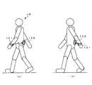
本発明に係る電子機器は、少なくとも他の電子機器との間で、各種の情報やデータを送受信する無線通信機能を備えているとともに、ユーザが携帯可能な形状、又は、ユーザの人体の所定の部位に装着可能な形状を有している。具体的には、本発明は、電子機器として、例えば図1(a)に示すように、腕時計型やリストバンド型等の、人体の所定の部位(手首等の四肢)に装着可能な形状を有するウェアラブル機器100Aを適用することができる。また、本発明は、電子機器として、例えば図1(b)に示すように、近年普及が著しいスマートフォン100Bやタブレット端末、図1(c)に示すように、登山等での行動軌跡を記録したり、ルート案内をしたりするアウトドア機器(いわゆる、GPSロガーやナビゲーション端末)100C等を、適用することができる。以下、図1に示したような各種の機器を、便宜的に「電子機器100」と総称する。 The electronic device according to the present invention has a wireless communication function for transmitting and receiving various information and data to / from at least other electronic devices, and has a shape that can be carried by the user or a predetermined human body. It has a shape that can be attached to the site. Specifically, the present invention provides an electronic device having a shape that can be attached to a predetermined part of a human body (limbs such as wrists) such as a wristwatch type or a wristband type as shown in FIG. The
そして、本実施形態においては、これらの電子機器100が図2に示すように、ユーザUSにより携帯、又は、ユーザの人体の所定の部位に装着されている。具体的には、例えばウェアラブル機器100AがユーザUSの手首や腕等の四肢に装着され、スマートフォン100Bやアウトドア機器100Cが、ユーザUSが人体に密着させて所持するバッグBAGやリュック等に収納される。ここで、本実施形態においては、少なくとも、ユーザUSにより複数の電子機器100が携帯又は装着され、かつ、当該複数の電子機器100のうち少なくとも一つが、ユーザUSの運動時の動きや姿勢等に応じて周期的な動きを繰り返す人体の部位(例えば四肢等)に携帯又は装着されている。さらに、ユーザUSにより携帯又は装着された複数の電子機器100間には、人体や金属等の無線通信に使用される電波の遮蔽物が部分的に介在している。このような電子機器100の配置は、意図的に設定されるものであってもよいし、ユーザUSの運動時の人体の動きや姿勢等により、必然的に設定されるものであってもよい。以下、説明の都合上、図2に示すように、無線通信により接続される一対の電子機器100のうち、ユーザUSの手首や腕等に装着されるウェアラブル機器100A等を、「第1の電子機器101」と記し、ユーザUSがバッグBAG等に収納して携帯するスマートフォン100B等を、「第2の電子機器102」と記す。 In the present embodiment, as shown in FIG. 2, these
なお、図2に示した各電子機器100(第1の電子機器101、第2の電子機器102)の配置は、一例を示したものに過ぎず、本発明はこれに限定されるものではない。例えば、バッグBAG等に収納されたスマートフォン100B等に替えて、ユーザUSの背中側の腰部等の衣類やベルト等にスマートフォン100Bやアウトドア機器100Cを直接クリップ止めしたり、ポケットに収納したりするものであってもよい。また、手首等に装着したウェアラブル機器100Aに替えて、例えばアウトドア機器100Cを手首等に装着したり、ユーザUSがスマートフォン100B等を直接手に持って携帯したりするものであってもよい。 The arrangement of each electronic device 100 (the first
電子機器100(第1の電子機器101、第2の電子機器102)に適用されるウェアラブル機器100Aやスマートフォン100B等は、具体的には、例えば図3に示すように、センサ部110と、入力操作部120と、特定機能部130と、通信回路部140と、演算回路部150と、メモリ部160と、電源供給部170と、を備えている。ここで、演算回路部150は、本発明に係る周期算出部、タイミング設定部、通信状態判定部、運動状態算出部に対応する。なお、本実施形態においては、図2に示したように、ユーザUSの手首に装着されるウェアラブル機器100A等の第1の電子機器101は、センサ部110を必須の構成として有しているが、バッグBAGに収納されるスマートフォン100B等の第2の電子機器102は、センサ部110を有していない構成であってもよい。 Specifically, the
センサ部110は、少なくとも、加速度センサや角速度センサ(ジャイロセンサ)、地磁気センサ、気圧センサ等の、ユーザUSの運動時の動きや姿勢等に応じた検出信号を出力するモーションセンサであって、これらのセンサのうちの少なくとも一つを有している。センサ部110において、ユーザの動きや姿勢等に基づいて常時又は周期的に出力される検出信号は、センサデータとして演算回路部150に送信されるとともに、時間データに関連付けられてメモリ部160に保存される。 The
具体的には、センサ部110がモーションセンサとして例えば加速度センサを有している場合、加速度センサは3軸加速度センサを有し、互いに直交する3軸の各々に沿った加速度(加速度信号)を検出して、加速度データとして出力する。本実施形態においては、例えば図4に示すように、ユーザUSの腕の延在方向のうち指先方向(図面下方向;法線方向)を+X軸方向、腕の延在方向(X軸)に直交し、ウォーキング中のユーザUSの進行方向(前方)側となる方向(図面左方向;接線方向)を+Y軸方向、X−Y平面(図面平面)に直交し、人体の外方側となる方向(図面手前方向)を+Z軸方向となるように、加速度センサを搭載した第1の電子機器101が手首UShに装着される。この場合、図2に示すように、ユーザUSがウォーキング中に進行方向(前方)及び後方に周期的に腕を振る動作は、図4に示すように、概ね、上記のX−Y平面内で行われ、腕振り動作の円弧状の軌跡に対して、ユーザUSの腕の延在方向であるX軸は法線方向となり、X軸に直交するY軸は接線方向となる。 Specifically, when the
なお、センサ部110により取得されるセンサデータは、後述する演算回路部150により、例えばウォーキング中の活動量や移動距離、移動速度、運動姿勢(フォーム)等の、ユーザUSの所定の運動状態を算出する際に使用されるものであってもよい。 The sensor data acquired by the
入力操作部120は、電子機器100の電源のオン、オフ操作や、各種の機能を設定したり実行させたりする操作の際に使用される。具体的には、入力操作部120は、例えば図1に示すように、電子機器100に適用されるウェアラブル機器100Aやスマートフォン100Bの筐体に設けられたボタンスイッチ122やキースイッチ(図示を省略)、後述する特定機能部130として設けられた表示部132の前面(ユーザUSの視野側)に配置されたタッチパネル124等の入力装置を有している。 The
特定機能部130は、後述する演算回路部150からの指示に従って、特定の機能を実行する。具体的には、特定機能部130は、例えば図1に示すように、ユーザに所定の情報を提供する表示部132や音響部134、画像や映像を撮影する撮像部(図示を省略)、ユーザの現在位置を計測するGPS回路部(図示を省略)等の機能を適用することができる。 The specific function unit 130 executes a specific function in accordance with an instruction from the
通信回路部140は、少なくとも、第1の電子機器101と第2の電子機器102とを所定の無線通信方式により接続し、各種の情報やデータを送受信する機能を有している。特に、本実施形態においては、通信回路部140は、上述したセンサ部110により取得されたセンサデータに基づいて算出されるユーザUSの腕振り動作(すなわち、第1の電子機器101と第2の電子機器102との位置関係の変化)の周期に基づいて、電子機器間の無線通信動作の接続タイミングが設定される。また、通信回路部140は、センサ部110により取得されたセンサデータや、当該センサデータに基づいて、後述する演算回路部150により算出されたユーザUSの運動状態に関する各種の情報やデータを、上記の接続タイミングで実行される無線通信動作により、第1の電子機器101と第2の電子機器102との間で相互に送受信する。ここで、通信回路部140において、電子機器間で各種の信号やデータを送受信する無線通信方式としては、例えばブルートゥース(Bluetooth(登録商標))通信や低消費電力型のブルートゥース(Bluetooth(登録商標) Low Energy)通信、無線LAN(Wireless Local Area Network)通信、NFC(Near Field Communication;近距離無線通信)等を適用することができる。 The
演算回路部150は、計時機能を備えるCPU(中央演算処理装置)やMPU(マイクロプロセッサ)等の演算処理装置(コンピュータ)であって、所定のプログラムを実行することにより、センサ部110におけるセンシング動作や、特定機能部130における特定の機能の実行動作、通信回路部140における無線通信動作等を制御する。特に、本実施形態においては、演算回路部150は、センサ部110により取得されるセンサデータに基づいて、ユーザUSの腕振り動作の周期を算出することにより、第1の電子機器101と第2の電子機器102との位置関係の変化パターンを判定し、当該腕振り動作の周期に基づいて通信回路部140における第1の電子機器101と第2の電子機器102との間の無線通信動作の接続タイミングを制御する。また、演算回路部150は、センサ部110により取得されたセンサデータに基づいて、ユーザUSの運動状態に関する各種の情報やデータを算出し、上記の接続タイミングで通信回路部140を介して、第1の電子機器101と第2の電子機器102との間で相互に送受信する制御を行う。 The
メモリ部160は、演算回路部150やセンサ部110、特定機能部130、通信回路部140等において取得されたり生成(算出)されたりしたデータ等を所定の記憶領域に保存する。なお、メモリ部160は、その一部又は全部が、例えばメモリカード等のリムーバブル記憶媒体としての形態を有し、電子機器100に対して着脱可能に構成されているものであってもよい。 The
電源供給部170は、電子機器100内部の各構成に駆動用の電力を供給する。電源供給部170は、例えば市販のボタン型電池等の一次電池や、リチウムイオン電池等の二次電池、あるいは、振動や光、熱、電磁波等のエネルギーにより発電する環境発電技術による電源等を、単独で、あるいは、併用して適用することができる。 The
(電子機器の制御方法)
次に、本実施形態に係る電子機器の制御方法(無線通信制御方法)について、図面を参照して説明する。なお、以下に示す運動支援方法は、ユーザUSの運動時の動きや姿勢等に応じて周期的な動きを繰り返す第1の電子機器101の演算回路部150において所定の制御プログラムを実行することにより実現される。(Electronic device control method)
Next, an electronic device control method (wireless communication control method) according to the present embodiment will be described with reference to the drawings. Note that the exercise support method described below is performed by executing a predetermined control program in the
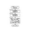
図5は、第1の実施形態に係る無線通信制御方法の一例を示すフローチャートであり、図6は、本実施形態に適用される接続タイミング設定処理の一例を示すフローチャートである。図7は、ウォーキング時における腕振り動作と、加速度データの信号波形との関係を示す概略図である。図8は、電子機器の位置と無線通信時の電波強度との関係の一例を示す実測データであり、図9は、電子機器間の位置関係が無線通信に及ぼす影響を説明するための概略図ある。図10は、電子機器間の無線通信動作における一般的な接続タイミングの例を示すタイミングチャートである。図11、図12は、本実施形態に係る無線通信制御方法における腕振り動作と電子機器間の無線通信動作における接続タイミングとの関係の一例を示すタイミングチャートである。 FIG. 5 is a flowchart illustrating an example of a wireless communication control method according to the first embodiment, and FIG. 6 is a flowchart illustrating an example of a connection timing setting process applied to the present embodiment. FIG. 7 is a schematic diagram showing a relationship between an arm swinging motion during walking and a signal waveform of acceleration data. FIG. 8 is actual measurement data showing an example of the relationship between the position of the electronic device and the radio wave intensity at the time of wireless communication, and FIG. 9 is a schematic diagram for explaining the influence of the positional relationship between the electronic devices on the wireless communication. is there. FIG. 10 is a timing chart illustrating an example of general connection timing in a wireless communication operation between electronic devices. FIG. 11 and FIG. 12 are timing charts showing an example of the relationship between the arm swinging operation and the connection timing in the wireless communication operation between electronic devices in the wireless communication control method according to the present embodiment.
本実施形態に係る無線通信制御方法においては、まず、ユーザUSが第1の電子機器101及び第2の電子機器102の入力操作部120を操作して電源をオンした後、第1の電子機器101を手首UShに装着し、第2の電子機器102をバッグBAGに収納する。そして、例えば図5のフローチャートに示すように、ユーザUSがウォーキングを開始する際に、第1の電子機器101及び第2の電子機器102の入力操作部120を操作することにより、演算回路部150は、第1の電子機器101と第2の電子機器102との間の無線通信動作を実行するとともに(ステップS102)、第1の電子機器101のセンサ部110におけるセンシング動作を実行する(ステップS104)。ここで、上記の無線通信動作とセンシング動作は、同時に開始されて実行されるものであってもよいし、異なるタイミングで開始されるものであってもよい。 In the wireless communication control method according to the present embodiment, first, after the user US operates the
具体的には、第1の電子機器101と第2の電子機器102とをブルートゥース(Bluetooth(登録商標))通信により接続する場合、例えば第2の電子機器102をマスタ側、第1の電子機器101をスレーブ側として、マスタ側の第2の電子機器102から一定の周期(例えば300m秒〜1秒間隔)でリンク確認信号が出力される。そして、スレーブ側の第1の電子機器101が、通信回路部140を介して受信されるリンク確認信号に対して、リンク確認動作を実行することにより第1の電子機器101と第2の電子機器102との間で無線通信が確立して相互に接続される。ここで、第1の電子機器101と第2の電子機器102とは、例えば、後述する接続タイミング設定処理により設定された、前回(又は直近)の接続タイミングを初期状態として無線通信が行われる。あるいは、例えば図10に示すように、スレーブ側の電子機器(第1の電子機器101に相当する)によるリンク確認動作が、マスタ側の電子機器(第2の電子機器102に相当する)から出力されるリンク確認信号の出力タイミングに同期し、かつ、当該出力タイミングの間隔の数倍の周期(例えば1秒の3倍;3秒間隔)に設定された状態を初期状態として無線通信が行われる。 Specifically, when the first
また、第1の電子機器101のセンサ部110におけるセンシング動作は、例えば加速度センサにより所定のサンプリング周波数でセンサデータ(加速度データ)が取得され、時間データに関連付けられてメモリ部160の所定の記憶領域に保存される。 The sensing operation in the
次いで、第1の電子機器101の演算回路部150は、センサ部110により取得され、メモリ部160に保存されたセンサデータに基づいて、ユーザUSのウォーキング時の腕振り動作の周期を算出する(ステップS106)。 Next, the
具体的には、ウォーキング時のユーザUSの腕振り動作は、例えば手首UShに装着された第1の電子機器101のセンサ部110(例えば加速度センサ)により取得されるセンサデータ(加速度データ)の特定の成分を観測することにより、その挙動を把握することができる。モーションセンサとして加速度センサを適用し、図4に示したように3軸方向を設定してウォーキングを行った場合、加速度センサから出力されるX軸方向の加速度成分(X軸成分)は、例えば図7(f)に示すように、略一定の周期で出力値が大きく変化する挙動を示す。ここで、図7(a)、(c)、(e)に示すように、第1の電子機器101を装着した腕を前方(図面左方)に振り出した状態、又は、後方(図面右方)に振り戻した状態では、重力加速度の成分が分散されるため、X軸成分の出力値は小さくなり極小値を示す。一方、図7(b)、(d)に示すように、腕振りの途中で腕を人体の真横で地面方向(図面下方)に下げた状態では、重力加速度がそのまま加算されるため、X軸成分の出力値は大きくなり極大値を示す。 Specifically, the arm swinging motion of the user US during walking is, for example, specifying sensor data (acceleration data) acquired by the sensor unit 110 (for example, an acceleration sensor) of the first
また、加速度センサから出力されるY軸方向の加速度成分(Y軸成分)は、例えば図7(f)に示すように、略一定の周期で出力値が小さく変化する挙動を示す。ここで、図7(a)、(e)に示すように、腕を前方(図面左方)に振り出した状態では、腕の延在方向(X軸)に直交し、かつ、進行方向(前方)となる+Y軸方向(図中、実線矢印で表示)に対して、反対方向(図中、点線矢印で表示)に振り戻しの力が加わるため、Y軸成分の出力値はわずかに小さくなり極小値を示す。一方、図7(c)に示すように、腕を後方(図面右方)に振り戻した状態では、+Y軸方向(図中、実線矢印で表示)と同方向(図中、点線矢印で表示)に振り出しの力が加わるため、Y軸成分の出力値はわずかに大きくなり極大値を示す。 Further, the acceleration component in the Y-axis direction (Y-axis component) output from the acceleration sensor exhibits a behavior in which the output value changes small at a substantially constant cycle, for example, as shown in FIG. Here, as shown in FIGS. 7A and 7E, when the arm is swung forward (leftward in the drawing), the arm is orthogonal to the extending direction of the arm (X axis) and the traveling direction (forward) ), The output value of the Y-axis component is slightly smaller because the reverse force is applied in the opposite direction (indicated by the dotted arrow in the figure) to the + Y-axis direction (indicated by the solid arrow in the figure) Indicates the minimum value. On the other hand, as shown in FIG. 7C, in the state where the arm is turned back (rightward in the drawing), the same direction as the + Y axis direction (indicated by a solid arrow in the figure) (indicated by a dotted arrow in the figure) ), The output value of the Y-axis component is slightly increased and exhibits a maximum value.
これにより、演算回路部150は、図7(f)に示したようなセンサデータの挙動に基づいて、例えばX軸成分の出力値が極小値を示し、かつ、Y軸成分の出力値が極小値を示した状態を、第1の電子機器101を装着した腕を前方に振り出した状態であると判定し、一方、X軸成分の出力値が極小値を示し、かつ、Y軸成分の出力値が極大値を示した状態を、腕を後方に振り戻した状態であると判定する。そして、演算回路部150は、これらの状態を判定したタイミングに基づいて、図7(a)〜(e)に示すような腕振り動作の一周期分の時間を算出する。算出された腕振り動作の周期は、メモリ部160の所定の記憶領域に保存される。 Accordingly, the
次いで、演算回路部150は、算出した腕振り動作の周期に基づいて、無線通信動作における適正な接続タイミングを設定する(ステップS108)。具体的には、例えば図6のフローチャートに示すように、演算回路部150は、まず、上記のステップS106により算出されたユーザUSの腕振り動作の周期と、図7(a)〜(e)に示した、当該周期の各タイミングにおける腕振り動作の状態(第1の電子機器101を装着した腕を前方に振り出した状態か、後方に振り戻した状態か、地面方向に向けた状態か等)とに基づいて、第1の電子機器101と第2の電子機器102との位置関係を判定する(ステップS122)。そして、演算回路部150は、第1の電子機器101と第2の電子機器102との位置関係が、無線通信動作による接続が安定している良好な通信状態となっている位置関係であるか否かを判定する(ステップS124)。 Next, the
ここで、第1の電子機器101と第2の電子機器102との間の通信状態は、双方の間の電波強度を実測することにより把握することができる。例えば図8に示すように、手首に第1の電子機器101を装着し、背中側の腰部に第2の電子機器102を携帯してウォーキングを行った場合の、第1の電子機器101と第2の電子機器102との間の電波強度は、第1の電子機器101と第2の電子機器102との位置関係に応じて大きく変化する。発明者の検証によれば、図8(a)に示すように、第1の電子機器101を装着した腕を前方に振り出した状態では、電波強度が例えば−93dBmと非常に弱く、第1の電子機器101と第2の電子機器102との間の通信状態が不安定かつ不良で、接続ができない可能性が高いという結果が得られた。このような実測結果は、図9(a)に示すように、腕を前方に振り出した状態では、第1の電子機器101と第2の電子機器102との間の距離が長く(遠く)なるうえ、第1の電子機器101と第2の電子機器102との間に電波の遮蔽物である人体が介在しているため、電波強度が弱まることによるものである。これに対して、図8(c)に示すように、腕を後方に振り戻した状態では例えば−63dBm、また、図8(b)に示すように、腕を人体の真横で地面方向に下げた状態では例えば−79dBmと電波強度が改善し、通信状態が安定かつ良好で、高い確率で接続できるという結果が得られた。このような実測結果は、図9(b)に示すように、腕を後方に振り戻した状態では、第1の電子機器101と第2の電子機器102との間の距離が短く(近く)なるうえ、第1の電子機器101と第2の電子機器102との間に電波の遮蔽物が介在しないため、電波強度が強まることによるものである。 Here, the communication state between the first
このことから、上記の実測結果を適用した場合には、演算回路部150は、電波強度が例えば−80〜−90dBmの範囲を境界として、第1の電子機器101と第2の電子機器102との間の通信状態の良否を判定することができる。この場合、ウォーキングにおける腕振り動作の一周期のうち、概ね3/4の期間(図7(b)〜(d)の動作期間)の通信状態が良好であると判定される。 From this, when the above-described actual measurement result is applied, the
なお、演算回路部150による電子機器間の通信状態の良否判定は、実際に第1の電子機器101と第2の電子機器102との間で無線通信を行った際の実測結果に基づくものであってもよいし、あるいは、予め第1の電子機器101と第2の電子機器102の装着位置が想定されている場合には、予め実施したシミュレーション実験の結果を用意し、その実験結果に基づくものであってもよい。 In addition, the quality determination of the communication state between the electronic devices by the
次いで、演算回路部150は、通信状態が良好であると判定された期間(図7(b)〜(d)の動作期間に相当する)に、第1の電子機器101におけるリンク確認動作の実行タイミング(接続タイミング)を設定するとともに、当該接続タイミングの間隔(周期)を腕振り動作の周期に一致しない値に設定する(ステップS126)。すなわち、図10に示すように、第1の電子機器101におけるリンク確認動作の実行タイミングの間隔が腕振り動作の周期に一致する場合、リンク確認動作(電子機器間の接続動作)の実行タイミングと前方への腕振り動作(図7(a)、(e)の動作状態)のタイミングとが重なる(一致する)と、第1の電子機器101と第2の電子機器102との間の通信状態が不良になる状態が毎回繰り返され、通信できない状態が継続することになる。一般に、このような通信不可状態が一定時間(タイムアウト時間)以上継続した場合には、電子機器間の接続状態が解除されて無線通信動作が強制終了される。 Next, the
これに対して、本実施形態においては、ウォーキングの動作周期である腕振り動作の周期と、電子機器間の接続動作の周期であるリンク確認動作の実行タイミングの間隔(周期)とが一致せず異なるように設定される。例えば図11に示すように、上記のステップS106において算出された、腕振り動作の周期Thが1秒であった場合、リンク確認動作の実行タイミングの間隔(周期)Tcが、腕振り動作の周期Thよりも短い、例えば0.6〜0.7秒(Thの0.6〜0.7倍)に設定される。これにより、図11に示すように、リンク確認動作の実行タイミングごとに、第1の電子機器101と第2の電子機器102の位置関係が毎回変化することになるので、電波強度が比較的強い状態(図7(b)〜(d)の動作状態;特定の状態)でリンク確認動作が実行されて接続される確率が高くなり、第1の電子機器101と第2の電子機器102との間で無線通信が確立された状態(接続状態)が継続することになる。なお、リンク確認動作の実行タイミングの間隔Tcは、上記のように腕振り動作の周期Thよりも短く設定するものに限定されず、腕振り動作の周期Thよりも長くなるよう(例えばThの1.2〜1.3倍)に設定してもよい。換言すると、リンク確認動作の実行タイミングの間隔Tcは、腕振り動作の周期Thの整数倍ではない、任意の倍率に設定されるものであればよい。 On the other hand, in this embodiment, the cycle of the arm swing operation that is the operation cycle of walking does not match the interval (cycle) of the execution timing of the link confirmation operation that is the cycle of the connection operation between electronic devices. Set differently. For example, as shown in FIG. 11, when the arm swing operation cycle Th calculated in step S106 is 1 second, the interval (cycle) Tc of the link check operation execution timing is the arm swing operation cycle. It is shorter than Th, for example, 0.6 to 0.7 seconds (0.6 to 0.7 times Th). As a result, as shown in FIG. 11, the positional relationship between the first
ここで、本実施形態に示したようにリンク確認動作の実行タイミングの間隔(周期)を設定した場合、リンク確認動作を繰り返すことにより、例えば図12に示すように、リンク確認動作(電子機器間の接続動作)の実行タイミングと、電波強度が弱い、前方への腕振り動作の状態の期間(図12中、「接続不可位置」と表記した期間)とが重なったり近似したりする場合がある。この場合、第1の電子機器101と第2の電子機器102との間の通信状態が悪化して接続ができなくなる可能性がある(図12中、「接続不可発生」と表記)。本実施形態においては、上述したように、腕振り動作の周期とリンク確認動作の実行タイミングの間隔(周期)とが一致しないように設定されている。これにより、図12に示すように、リンク確認動作の実行タイミングごとに、第1の電子機器101と第2の電子機器102の位置関係が毎回変化する。したがって、リンク確認動作の実行タイミングと前方への腕振り動作の状態が重なる状態が生じた場合であっても、次回以降のリンク確認動作は、電波強度が比較的強い、腕振り動作の状態の期間(図12中、「接続可能位置」と表記した期間)に実行されることになるので(図12中、「再接続可能(1)」、「再接続可能(2)」と表記)、第1の電子機器101と第2の電子機器102とが再び良好な通信状態で接続されることになる。 Here, when the interval (cycle) of the execution timing of the link confirmation operation is set as shown in the present embodiment, by repeating the link confirmation operation, for example, as shown in FIG. Connection timing) and the period of the arm swinging motion state where the radio field intensity is weak (the period indicated as “connection impossible position” in FIG. 12) may overlap or approximate. . In this case, there is a possibility that the communication state between the first
次いで、演算回路部150は、上記のステップS108において新たに設定された無線通信動作の接続タイミング(リンク確認動作の実行タイミング及びその周期)が、現在設定されている接続タイミングに対して変化があるか(異なるか)否かを判定する(ステップS110)。接続タイミングに変化がある場合(ステップS110のYes)には、演算回路部150は、現在の接続タイミングを、ステップS108において新たに設定された接続タイミングに変更する(ステップS112)。新たに設定された接続タイミングは、メモリ部160の所定の記憶領域に保存される。一方、接続タイミングに変化がない場合(ステップS110のNo)には、演算回路部150は、現在の接続タイミングを維持して、上記のステップS108に戻って、センサデータに基づいて算出された腕振り動作の周期に基づいて、無線通信動作における適正な接続タイミングを設定する処理を繰り返し実行する。 Next, in the
次いで、演算回路部150は、変更後の接続タイミングに基づいて、第1の電子機器101と第2の電子機器102との間の無線通信動作を実行する(ステップS114)。これにより、演算回路部150は、センサ部110により取得されたセンサデータや、当該センサデータに基づいて算出されたユーザUSの運動状態に関する各種の情報やデータを、通信回路部140を介して、第1の電子機器101と第2の電子機器102との間で相互に送受信する。その後、演算回路部150は、ステップS116において、無線通信動作の終了判断をするまで、ステップS102に戻って、上述した一連の処理動作を定期的に繰り返し実行する。 Next, the
なお、上述した無線通信制御方法においては、ユーザの腕振り動作の周期を算出するためのセンサデータとして、加速度データを用いた場合について説明したが、これに限定されるものではない。本発明は、第1の電子機器101を装着した人体の部位の動きや姿勢等に応じて検出信号が周期的に変化するものであれば、角速度データや地磁気データ、気圧データ等の他のセンサデータを、単独で用いるものであってもよいし、複数のセンサデータを組み合わせて用いるものであってもよい。また、電子機器間に適用される無線通信方式についても、ブルートゥース(Bluetooth(登録商標))通信に限定されるものではなく、一方の電子機器から規則的に出力されるリンク確認信号に基づいて、他方の電子機器がリンク確認動作を実行するものであれば、ブルートゥース(Bluetooth(登録商標))LE通信や無線LAN通信、NFC等の無線通信方式を適用するものであってもよい。 In the wireless communication control method described above, the case where acceleration data is used as the sensor data for calculating the period of the user's arm swing motion has been described, but the present invention is not limited to this. The present invention is applicable to other sensors such as angular velocity data, geomagnetic data, and atmospheric pressure data as long as the detection signal periodically changes in accordance with the movement or posture of the part of the human body wearing the first
このように、本実施形態においては、センサ部110により取得されたセンサデータに基づいて、ユーザUSの腕振り動作の周期(手首UShに装着された第1の電子機器101とバッグBAGに収納された第2の電子機器102との位置関係の変化パターン)を算出する。そして、算出された腕振り動作の周期に基づいて、電子機器間の無線通信動作における接続タイミングを設定する。ここで、本実施形態においては、第1の電子機器101におけるリンク確認動作の実行タイミングの間隔(周期)を、腕振り動作の周期に一致しない(異なる)ようにずらして設定することにより、電子機器間の電波強度が弱く接続しにくい状態を回避して、電波強度が比較的強く良好な接続が可能な状態の期間にリンク確認動作が実行される。 As described above, in the present embodiment, based on the sensor data acquired by the
これにより、ユーザが電子機器を携帯又は人体に装着して使用する場合であっても、電子機器間の電波強度が弱く、接続しにくい状態でリンク確認動作が繰り返し実行される状態を防止することができ、電子機器間の接続状態を高い確率で保持して通信品質を向上させることができる。また、電子機器に設けられたモーションセンサにより取得されるセンサデータに基づいて、ユーザの周期的な動きを把握する手法を用いているので、本実施形態に係る電子機器を使用するユーザや、電子機器の装着又は携帯する位置や方法に限定されることなく、電子機器間の通信品質を向上させることができる。 This prevents a state in which the link check operation is repeatedly executed in a state in which the radio wave strength between the electronic devices is weak and difficult to connect even when the user uses the electronic device on a portable or human body. It is possible to improve the communication quality by maintaining the connection state between electronic devices with a high probability. In addition, since a method for grasping the periodic movement of the user based on sensor data acquired by a motion sensor provided in the electronic device is used, the user who uses the electronic device according to the present embodiment, the electronic device The communication quality between electronic devices can be improved without being limited to the position or method of mounting or carrying the device.
<第2の実施形態>
次に、本発明に係る電子機器の第2の実施形態について図面を参照して説明する。
図13は、第2の実施形態に係る無線通信制御方法に適用される接続タイミング設定処理の一例を示すフローチャートである。図14は、本実施形態に係る無線通信制御方法における腕振り動作と電子機器間の無線通信動作における接続タイミングとの関係の一例を示すタイミングチャートである。ここで、上述した第1の実施形態と同等の処理動作については、その説明を簡略化する。<Second Embodiment>
Next, a second embodiment of the electronic apparatus according to the invention will be described with reference to the drawings.
FIG. 13 is a flowchart illustrating an example of a connection timing setting process applied to the wireless communication control method according to the second embodiment. FIG. 14 is a timing chart showing an example of the relationship between the arm swing operation and the connection timing in the wireless communication operation between electronic devices in the wireless communication control method according to the present embodiment. Here, the description of the processing operation equivalent to that of the first embodiment will be simplified.
上述した第1の実施形態においては、ユーザUSの腕振り動作の周期に基づいて、電子機器間の無線通信動作の接続タイミングを設定する際に、第1の電子機器101におけるリンク確認動作の実行タイミングの間隔(周期)を、腕振り動作の周期に一致しないように設定する場合について説明した。第2の実施形態においては、上記の接続タイミングを設定する際に、第1の電子機器101におけるリンク確認動作の実行タイミングの間隔(周期)を腕振り動作の周期に一致させ、かつ、その実行タイミングを電子機器間の電波強度が弱く接続しにくい状態の期間を回避して設定することを特徴としている。 In the first embodiment described above, when the connection timing of the wireless communication operation between the electronic devices is set based on the period of the arm swinging operation of the user US, the link confirmation operation in the first
第2の実施形態においては、上述した第1の本実施形態に示した無線通信制御方法(図5のフローチャート参照)に適用される、電子機器間の無線通信動作の接続タイミングを設定する処理(ステップS108)において、以下の処理動作が実行される。すなわち、例えば図13のフローチャートに示すように、演算回路部150は、まず、上述した第1の実施形態と同様に、ユーザUSの腕振り動作の周期と、各タイミングにおける動作状態とに基づいて電子機器間の位置関係を判定(ステップS222)した後、その位置関係に基づいて電子機器間の通信状態を判定する(ステップS224)。 In the second embodiment, processing for setting connection timing of wireless communication operation between electronic devices applied to the wireless communication control method (see the flowchart of FIG. 5) shown in the first embodiment described above ( In step S108), the following processing operations are executed. That is, for example, as illustrated in the flowchart of FIG. 13, the
次いで、演算回路部150は、図14に示すように、通信状態が良好であると判定された期間(図14中、「接続可能位置」と表記した期間)に、第1の電子機器101におけるリンク確認動作の実行タイミングを設定するとともに、当該実行タイミングの間隔(周期)が腕振り動作の周期に一致するように設定する(ステップS226)。例えば図14に示すように、腕振り動作の周期Thが1秒であった場合、リンク確認動作の実行タイミングの間隔(周期)Tcが、腕振り動作の周期Thと同一の1秒に設定される。これにより、腕振り動作の一周期のうち、電波強度が比較的強く良好な接続が可能な動作状態の特定の期間に、リンク確認動作(電子機器間の接続動作)が毎回実行されることになり、第1の電子機器101と第2の電子機器102との間で無線通信が確立された状態(接続状態)が継続することになる。 Next, as illustrated in FIG. 14, the
これにより、上述した第1の実施形態と同様に、ユーザが電子機器を携帯又は人体に装着して使用する場合であっても、電子機器間の電波強度が弱く、接続しにくい状態でリンク確認動作が繰り返し実行される状態を防止することができ、電子機器間の接続状態を確実に保持して通信品質をより向上させることができる。 As a result, as in the first embodiment described above, even when the user uses the electronic device while being carried or attached to a human body, the link confirmation is performed in a state where the radio wave strength between the electronic devices is weak and difficult to connect. A state in which the operation is repeatedly executed can be prevented, and the connection state between the electronic devices can be reliably maintained and the communication quality can be further improved.
以上、本発明のいくつかの実施形態について説明したが、本発明は、上述した実施形態に限定されるものではなく、特許請求の範囲に記載された発明とその均等の範囲を含むものである。
以下に、本願出願の当初の特許請求の範囲に記載された発明を付記する。As mentioned above, although some embodiment of this invention was described, this invention is not limited to embodiment mentioned above, It includes the invention described in the claim, and its equivalent range.
Hereinafter, the invention described in the scope of claims of the present application will be appended.
(付記)
[1]
電子機器であって、
無線通信を実行する無線通信回路部と、
前記電子機器の動きに対応するセンサデータを出力するセンサ部と、
前記無線通信回路部を制御する演算回路部と、
を備え、
前記演算回路部は、
前記電子機器が利用者に装着又は携帯されて周期的な動きをしている状態で、前記無線通信回路部が、前記利用者に装着又は携帯されている他の電子機器と前記無線通信を実行するときに、前記センサデータに基づいて前記周期的な動きの第1の周期を算出して、前記無線通信により前記電子機器を前記他の電子機器と接続する接続タイミングを前記第1の周期に基づいて設定することを特徴とする電子機器。(Appendix)
[1]
Electronic equipment,
A wireless communication circuit unit for performing wireless communication;
A sensor unit that outputs sensor data corresponding to the movement of the electronic device;
An arithmetic circuit unit for controlling the wireless communication circuit unit;
With
The arithmetic circuit unit is:
The wireless communication circuit unit performs the wireless communication with another electronic device worn or carried by the user while the electronic device is worn or carried by the user and periodically moves. A first cycle of the periodic movement is calculated based on the sensor data, and a connection timing for connecting the electronic device to the other electronic device by the wireless communication is set to the first cycle. An electronic device characterized by setting based on the above.
[2]
前記タイミング設定部は、前記接続タイミングを第2の周期を有する周期的なタイミングに設定し、前記第2の周期を前記第1の周期と異なる値に設定することを特徴とする[1]に記載の電子機器。[2]
[1], wherein the timing setting unit sets the connection timing to a periodic timing having a second period, and sets the second period to a value different from the first period. The electronic device described.
[3]
前記タイミング設定部は、前記接続タイミングを第2の周期を有する周期的なタイミングに設定し、前記第2の周期を前記第1の周期と同じ値に設定することを特徴とする[1]に記載の電子機器。[3]
The timing setting unit sets the connection timing to a periodic timing having a second period, and sets the second period to the same value as the first period. [1] The electronic device described.
[4]
前記演算回路部は、
前記センサデータに基づく前記電子機器と前記他の電子機器との位置関係が、前記無線通信による接続が安定している位置関係であるか否かを判定し、
前記第1の周期、及び、前記位置関係の判定に基づいて、前記第2の周期を設定することを特徴とする[2]又は[3]に記載の電子機器。[4]
The arithmetic circuit unit is:
Determining whether the positional relationship between the electronic device and the other electronic device based on the sensor data is a positional relationship in which the connection by the wireless communication is stable;
The electronic apparatus according to [2] or [3], wherein the second period is set based on the determination of the first period and the positional relationship.
[5]
前記センサ部は、前記電子機器が装着又は携帯された前記利用者の身体の動きを、直交する3軸方向の成分として検出し、
前記演算回路部は、前記3軸方向の前記センサデータに基づいて、前記第1の周期を算出することを特徴とする[1]乃至[4]のいずれかに記載の電子機器。[5]
The sensor unit detects the movement of the user's body worn or carried by the electronic device as a component in three orthogonal directions,
The electronic device according to any one of [1] to [4], wherein the arithmetic circuit unit calculates the first period based on the sensor data in the three-axis directions.
[6]
電子機器の制御方法であって、
前記電子機器は、無線通信を実行する無線通信回路部と、前記電子機器の動きに対応するセンサデータを出力するセンサ部と、前記無線通信回路部を制御する演算回路部と、を備え、
前記電子機器が利用者に装着又は携帯されて周期的な動きをしている状態で、前記無線通信回路部が、前記利用者に装着又は携帯されている他の電子機器と前記無線通信を実行するときに、前記センサデータに基づいて前記周期的な動きの周期を算出し、
前記無線通信により前記電子機器を前記他の電子機器と接続する接続タイミングを、前記第1の周期に基づいて設定する、
ことを特徴とする電子機器の制御方法。[6]
An electronic device control method comprising:
The electronic device includes a wireless communication circuit unit that performs wireless communication, a sensor unit that outputs sensor data corresponding to movement of the electronic device, and an arithmetic circuit unit that controls the wireless communication circuit unit,
The wireless communication circuit unit performs the wireless communication with another electronic device worn or carried by the user while the electronic device is worn or carried by the user and periodically moves. When calculating the period of the periodic movement based on the sensor data,
A connection timing for connecting the electronic device to the other electronic device by the wireless communication is set based on the first cycle.
A method for controlling an electronic device.
[7]
電子機器の制御プログラムであって、
前記電子機器は、無線通信を実行する無線通信回路部と、前記電子機器の動きに対応するセンサデータを出力するセンサ部と、前記無線通信回路部を制御するコンピュータと、を備え、
前記コンピュータに、
前記電子機器が利用者に装着又は携帯されて周期的な動きをしている状態で、前記無線通信回路部が、前記利用者に装着又は携帯されている他の電子機器と前記無線通信を実行するときに、前記センサデータに基づいて前記周期的な動きの周期を算出させ、
前記無線通信により前記電子機器を前記他の電子機器と接続する接続タイミングを、前記第1の周期に基づいて設定させる、
ことを特徴とする電子機器の制御プログラム。[7]
An electronic device control program,
The electronic device includes a wireless communication circuit unit that performs wireless communication, a sensor unit that outputs sensor data corresponding to the movement of the electronic device, and a computer that controls the wireless communication circuit unit.
In the computer,
The wireless communication circuit unit performs the wireless communication with another electronic device worn or carried by the user while the electronic device is worn or carried by the user and periodically moves. When calculating the period of the periodic movement based on the sensor data,
The connection timing for connecting the electronic device to the other electronic device by the wireless communication is set based on the first period.
A control program for an electronic device.
100 電子機器
101 第1の電子機器
102 第2の電子機器
110 センサ部
120 入力操作部
130 特定機能部
140 通信回路部
150 演算回路部
160 メモリ部
US ユーザDESCRIPTION OF
Claims (4)
Translated fromJapanese前記利用者の前記一の位置とは異なる位置に装着又は携帯される他の機器と無線通信による接続を間欠的に実行する無線通信手段と、
前記電子機器の動きに関連するセンサデータを取得するセンサデータ取得手段と、
前記センサデータに基づいて前記電子機器の周期的な動きの周期を取得し、前記無線通信により前記電子機器を前記他の機器と接続する接続タイミングの間隔を、前記周期の整数倍ではない倍率に設定する接続タイミング制御手段と、
を備えることを特徴とする電子機器。An electronic device thatis worn or carried at one location of a user ,
Wireless communication means for intermittently performing connection by wireless communication with another devicemounted or carried at a position different from the one position of the user ;
Sensor data acquisition means for acquiring sensor data related to the movement of the electronic device;
A period of periodic movement of the electronic device is acquired based on the sensor data, and a connection timinginterval for connecting the electronic device to the other device by the wireless communicationis set to a magnification that is not an integral multiple of the cycle. Connection timing control means to be set;
An electronic device comprising:
前記利用者の前記一の位置とは異なる位置に装着又は携帯される他の機器と無線通信による接続を間欠的に実行する無線通信工程と、
前記電子機器の動きに関連するセンサデータを取得するセンサデータ取得工程と、
前記センサデータに基づいて前記電子機器の周期的な動きの周期を取得し、前記無線通信により前記電子機器を前記他の機器と接続する接続タイミングの間隔を、前記周期の整数倍ではない倍率に設定する接続タイミング制御工程と、
を有することを特徴とする電子機器の制御方法。A method for controllingan electronic deviceto be mounted or carried at one position of a user ,
A wireless communication step of intermittently performing connection by wireless communication with another devicemounted or carried at a position different from the one position of the user ;
A sensor data acquisition step of acquiring sensor data related to the movement of the electronic device;
A period of periodic movement of the electronic device is acquired based on the sensor data, and a connection timinginterval for connecting the electronic device to the other device by the wireless communicationis set to a magnification that is not an integral multiple of the cycle. Connection timing control process to be set;
A method for controlling an electronic device, comprising:
前記利用者の前記一の位置とは異なる位置に装着又は携帯される他の機器と無線通信による接続を間欠的に実行する無線通信手段、
前記電子機器の動きに関連するセンサデータを取得するセンサデータ取得手段、
前記センサデータに基づいて前記電子機器の周期的な動きの周期を取得し、前記無線通信により前記電子機器を前記他の機器と接続する接続タイミングの間隔を、前記周期の整数倍ではない倍率に設定する接続タイミング制御手段、
として実行させることを特徴とする電子機器の制御プログラム。A computer ofan electronic devicethat is mounted or carried at one location of the user,
Wireless communication means for intermittently performing connection by wireless communication with another devicemounted or carried at a position different from the one position of the user ;
Sensor data acquisition means for acquiring sensor data related to the movement of the electronic device;
A period of periodic movement of the electronic device is acquired based on the sensor data, and a connection timinginterval for connecting the electronic device to the other device by the wireless communicationis set to a magnification that is not an integral multiple of the cycle. Connection timing control means to be set;
An electronic device control program that is executed as:
Priority Applications (3)
| Application Number | Priority Date | Filing Date | Title |
|---|---|---|---|
| JP2015167399AJP6573071B2 (en) | 2015-08-27 | 2015-08-27 | Electronic device, control method therefor, and control program |
| CN201610717087.3ACN106488389B (en) | 2015-08-27 | 2016-08-24 | Electronic device and control method thereof |
| US15/248,122US10362620B2 (en) | 2015-08-27 | 2016-08-26 | Electronic device, method for controlling same and computer-readable storage medium storing control program |
Applications Claiming Priority (1)
| Application Number | Priority Date | Filing Date | Title |
|---|---|---|---|
| JP2015167399AJP6573071B2 (en) | 2015-08-27 | 2015-08-27 | Electronic device, control method therefor, and control program |
Publications (3)
| Publication Number | Publication Date |
|---|---|
| JP2017042380A JP2017042380A (en) | 2017-03-02 |
| JP2017042380A5 JP2017042380A5 (en) | 2018-08-23 |
| JP6573071B2true JP6573071B2 (en) | 2019-09-11 |
Family
ID=58097238
Family Applications (1)
| Application Number | Title | Priority Date | Filing Date |
|---|---|---|---|
| JP2015167399AActiveJP6573071B2 (en) | 2015-08-27 | 2015-08-27 | Electronic device, control method therefor, and control program |
Country Status (3)
| Country | Link |
|---|---|
| US (1) | US10362620B2 (en) |
| JP (1) | JP6573071B2 (en) |
| CN (1) | CN106488389B (en) |
Families Citing this family (3)
| Publication number | Priority date | Publication date | Assignee | Title |
|---|---|---|---|---|
| WO2019107888A1 (en)* | 2017-11-29 | 2019-06-06 | 삼성전자 주식회사 | Method for rf communication connection using electronic device and user touch input |
| JP7131266B2 (en)* | 2018-10-01 | 2022-09-06 | カシオ計算機株式会社 | Information terminal, wrist information device, and system equipped with them |
| US11537093B2 (en)* | 2019-03-08 | 2022-12-27 | Citizen Watch Co., Ltd. | Mobile device and mobile device system |
Family Cites Families (32)
| Publication number | Priority date | Publication date | Assignee | Title |
|---|---|---|---|---|
| JP2003344095A (en)* | 2002-05-23 | 2003-12-03 | Canon Electronics Inc | Apparatus for measuring number of steps or walking speed or walking distance |
| JP2005342254A (en)* | 2004-06-03 | 2005-12-15 | Matsushita Electric Ind Co Ltd | Walking cycle detection device |
| US20050181734A1 (en)* | 2005-01-21 | 2005-08-18 | Knightsbridge Wireless Inc. | Automatic connection of a mobile device to a wireless network |
| US7353034B2 (en)* | 2005-04-04 | 2008-04-01 | X One, Inc. | Location sharing and tracking using mobile phones or other wireless devices |
| US20090063193A1 (en)* | 2007-08-31 | 2009-03-05 | Mike Barton | Dashboard diagnostics for wireless patient communicator |
| US9591118B2 (en)* | 2009-01-01 | 2017-03-07 | Intel Corporation | Pose to device mapping |
| US8033959B2 (en) | 2009-05-18 | 2011-10-11 | Adidas Ag | Portable fitness monitoring systems, and applications thereof |
| TW201107952A (en)* | 2009-08-25 | 2011-03-01 | Elitegroup Computer Sys Co Ltd | Power-supply expansion system and its method thereof |
| WO2011055477A1 (en)* | 2009-11-06 | 2011-05-12 | パナソニック株式会社 | Communication apparatus and communication method |
| US8907782B2 (en)* | 2010-06-30 | 2014-12-09 | Welch Allyn, Inc. | Medical devices with proximity detection |
| US8774829B2 (en)* | 2010-07-16 | 2014-07-08 | Qualcomm Incorporated | Sensor node positioning for location determination |
| JP5589810B2 (en)* | 2010-12-06 | 2014-09-17 | カシオ計算機株式会社 | Electronic clock |
| JP2012199749A (en)* | 2011-03-22 | 2012-10-18 | Seiko Epson Corp | Circuit device, communication device, and communication system |
| US20150135284A1 (en)* | 2011-06-10 | 2015-05-14 | Aliphcom | Automatic electronic device adoption with a wearable device or a data-capable watch band |
| JP5509153B2 (en)* | 2011-07-20 | 2014-06-04 | 日本電信電話株式会社 | Gait analysis method, gait analysis device and program thereof |
| JP6000631B2 (en)* | 2012-05-10 | 2016-10-05 | オリンパス株式会社 | Wireless communication apparatus, wireless communication system, antenna control method, and program |
| US8862215B2 (en)* | 2013-01-16 | 2014-10-14 | Polar Electro Oy | Reconfigurable sensor devices monitoring physical exercise |
| KR102065407B1 (en)* | 2013-07-11 | 2020-01-13 | 엘지전자 주식회사 | Digital device amd method for controlling the same |
| US20150119105A1 (en)* | 2013-10-30 | 2015-04-30 | Assaf Amgar | Apparatus and method for controlling the powering of wireless mobile device activation |
| JP5888309B2 (en)* | 2013-10-31 | 2016-03-22 | カシオ計算機株式会社 | Training support apparatus and system, form analysis apparatus and method, and program |
| US9504425B2 (en)* | 2013-12-16 | 2016-11-29 | Verily Life Sciences Llc | Method of location coordination via wireless protocol between multiple devices |
| TW201525716A (en)* | 2013-12-23 | 2015-07-01 | Qisda Corp | Pairing method for mobile devices |
| US9521236B2 (en)* | 2013-12-24 | 2016-12-13 | Incipio, Llc | Wireless visual notification device for mobile device |
| KR101509596B1 (en)* | 2014-05-08 | 2015-04-08 | 경북대학교 산학협력단 | Mobile device system for remote starting and management of vehicle |
| US9210627B1 (en)* | 2014-05-28 | 2015-12-08 | Apple Inc. | User context aware throttling of transition attempts to connected mode |
| KR101698098B1 (en)* | 2014-07-23 | 2017-01-19 | 엘지전자 주식회사 | Mobile terminal and control method for the mobile terminal |
| US20160059120A1 (en)* | 2014-08-28 | 2016-03-03 | Aquimo, Llc | Method of using motion states of a control device for control of a system |
| KR20160047273A (en)* | 2014-10-22 | 2016-05-02 | 엘지전자 주식회사 | Watch type terminal |
| US10359327B2 (en)* | 2014-12-01 | 2019-07-23 | Ebay Inc. | Waist measuring belt |
| KR101637368B1 (en)* | 2015-03-10 | 2016-07-07 | 엘지전자 주식회사 | Watch type mobile terminal |
| CN104820579B (en)* | 2015-04-10 | 2019-01-22 | 苏州尚德智产通信技术有限公司 | A kind of sensor-based system and method for sensing comprising mobile terminal and peripheral device |
| US10244057B2 (en)* | 2015-10-09 | 2019-03-26 | Adobe Systems Incorporated | Techniques for associating and sharing data from multiple local devices |
- 2015
- 2015-08-27JPJP2015167399Apatent/JP6573071B2/enactiveActive
- 2016
- 2016-08-24CNCN201610717087.3Apatent/CN106488389B/enactiveActive
- 2016-08-26USUS15/248,122patent/US10362620B2/enactiveActive
Also Published As
| Publication number | Publication date |
|---|---|
| CN106488389A (en) | 2017-03-08 |
| CN106488389B (en) | 2019-11-12 |
| US10362620B2 (en) | 2019-07-23 |
| US20170064767A1 (en) | 2017-03-02 |
| JP2017042380A (en) | 2017-03-02 |
Similar Documents
| Publication | Publication Date | Title |
|---|---|---|
| JP6486439B2 (en) | Motion capture system, method and program | |
| TWI610084B (en) | Techniques for determining movements based on sensor measurements from a plurality of mobile devices co-located with a person | |
| CN106959377B (en) | Electronic device and angular velocity acquisition method thereof | |
| CN103876755B (en) | Sensing data extraction system and sensing data abstracting method | |
| JP6340377B2 (en) | How to communicate sensor data between devices | |
| US9595181B2 (en) | Wearable device assisting smart media application and vice versa | |
| JP5811360B2 (en) | Exercise information display system, exercise information display method, and exercise information display program | |
| EP3470044A1 (en) | Navigation apparatus and method | |
| US20170227375A1 (en) | Calibration of a primary pedometer device using a secondary pedometer device | |
| US20140172136A1 (en) | Exercise support device, exercise support method, and computer-readable storage medium having exercise support program stored therein | |
| JP2015058167A (en) | Exercise support device, exercise support method, and exercise support program | |
| CN104586399A (en) | Training supporting apparatus and system for supporting training of walking and/or running | |
| JP2017505908A (en) | Object motion determination method and system | |
| JP2015116288A (en) | Exercise information display system, exercise information display method, and exercise information display program | |
| JP6573071B2 (en) | Electronic device, control method therefor, and control program | |
| JP6094476B2 (en) | Imaging system, control method therefor, and control program therefor | |
| JP2015154988A (en) | Sensor data extraction system, sensor data extraction method, and sensor data extraction program | |
| GB2569101A (en) | Wearable exercise assessment system | |
| JP2009125229A (en) | Motion measuring device | |
| CN108027590A (en) | User interface for Watchcase is arranged | |
| JP6337980B2 (en) | Exercise state detection apparatus, control method thereof, and control program thereof | |
| JP2016220879A (en) | Motion measurement device, motion measurement system, motion measurement method, and motion measurement program | |
| JP2015184002A (en) | Electronic device system, terminal device, electronic device system control method, and control program | |
| EP3173905B1 (en) | Enhancing controlling of haptic output | |
| US12039097B1 (en) | Method and system for gathering and analyzing motion data |
Legal Events
| Date | Code | Title | Description |
|---|---|---|---|
| A521 | Written amendment | Free format text:JAPANESE INTERMEDIATE CODE: A523 Effective date:20180711 | |
| A621 | Written request for application examination | Free format text:JAPANESE INTERMEDIATE CODE: A621 Effective date:20180711 | |
| A131 | Notification of reasons for refusal | Free format text:JAPANESE INTERMEDIATE CODE: A131 Effective date:20190412 | |
| A977 | Report on retrieval | Free format text:JAPANESE INTERMEDIATE CODE: A971007 Effective date:20190417 | |
| A521 | Written amendment | Free format text:JAPANESE INTERMEDIATE CODE: A523 Effective date:20190524 | |
| TRDD | Decision of grant or rejection written | ||
| A01 | Written decision to grant a patent or to grant a registration (utility model) | Free format text:JAPANESE INTERMEDIATE CODE: A01 Effective date:20190717 | |
| A61 | First payment of annual fees (during grant procedure) | Free format text:JAPANESE INTERMEDIATE CODE: A61 Effective date:20190730 | |
| R150 | Certificate of patent or registration of utility model | Ref document number:6573071 Country of ref document:JP Free format text:JAPANESE INTERMEDIATE CODE: R150 |