JP6571719B2 - Method and apparatus for treating hypertension by percutaneous ultrasound renal nerve removal - Google Patents
Method and apparatus for treating hypertension by percutaneous ultrasound renal nerve removalDownload PDFInfo
- Publication number
- JP6571719B2 JP6571719B2JP2017125690AJP2017125690AJP6571719B2JP 6571719 B2JP6571719 B2JP 6571719B2JP 2017125690 AJP2017125690 AJP 2017125690AJP 2017125690 AJP2017125690 AJP 2017125690AJP 6571719 B2JP6571719 B2JP 6571719B2
- Authority
- JP
- Japan
- Prior art keywords
- transducer
- renal
- renal artery
- ultrasonic
- ultrasonic transducer
- Prior art date
- Legal status (The legal status is an assumption and is not a legal conclusion. Google has not performed a legal analysis and makes no representation as to the accuracy of the status listed.)
- Active
Links
Images


Classifications
- A—HUMAN NECESSITIES
- A61—MEDICAL OR VETERINARY SCIENCE; HYGIENE
- A61M—DEVICES FOR INTRODUCING MEDIA INTO, OR ONTO, THE BODY; DEVICES FOR TRANSDUCING BODY MEDIA OR FOR TAKING MEDIA FROM THE BODY; DEVICES FOR PRODUCING OR ENDING SLEEP OR STUPOR
- A61M25/00—Catheters; Hollow probes
- A61M25/0067—Catheters; Hollow probes characterised by the distal end, e.g. tips
- A61M25/0082—Catheter tip comprising a tool
- A—HUMAN NECESSITIES
- A61—MEDICAL OR VETERINARY SCIENCE; HYGIENE
- A61N—ELECTROTHERAPY; MAGNETOTHERAPY; RADIATION THERAPY; ULTRASOUND THERAPY
- A61N7/00—Ultrasound therapy
- A61N7/02—Localised ultrasound hyperthermia
- A61N7/022—Localised ultrasound hyperthermia intracavitary
- A—HUMAN NECESSITIES
- A61—MEDICAL OR VETERINARY SCIENCE; HYGIENE
- A61M—DEVICES FOR INTRODUCING MEDIA INTO, OR ONTO, THE BODY; DEVICES FOR TRANSDUCING BODY MEDIA OR FOR TAKING MEDIA FROM THE BODY; DEVICES FOR PRODUCING OR ENDING SLEEP OR STUPOR
- A61M25/00—Catheters; Hollow probes
- A61M25/0067—Catheters; Hollow probes characterised by the distal end, e.g. tips
- A61M25/0068—Static characteristics of the catheter tip, e.g. shape, atraumatic tip, curved tip or tip structure
- A—HUMAN NECESSITIES
- A61—MEDICAL OR VETERINARY SCIENCE; HYGIENE
- A61M—DEVICES FOR INTRODUCING MEDIA INTO, OR ONTO, THE BODY; DEVICES FOR TRANSDUCING BODY MEDIA OR FOR TAKING MEDIA FROM THE BODY; DEVICES FOR PRODUCING OR ENDING SLEEP OR STUPOR
- A61M25/00—Catheters; Hollow probes
- A61M25/10—Balloon catheters
- A61M25/1002—Balloon catheters characterised by balloon shape
- A—HUMAN NECESSITIES
- A61—MEDICAL OR VETERINARY SCIENCE; HYGIENE
- A61N—ELECTROTHERAPY; MAGNETOTHERAPY; RADIATION THERAPY; ULTRASOUND THERAPY
- A61N7/00—Ultrasound therapy
- A—HUMAN NECESSITIES
- A61—MEDICAL OR VETERINARY SCIENCE; HYGIENE
- A61B—DIAGNOSIS; SURGERY; IDENTIFICATION
- A61B17/00—Surgical instruments, devices or methods
- A61B17/00234—Surgical instruments, devices or methods for minimally invasive surgery
- A61B2017/00292—Surgical instruments, devices or methods for minimally invasive surgery mounted on or guided by flexible, e.g. catheter-like, means
- A61B2017/003—Steerable
- A61B2017/00318—Steering mechanisms
- A61B2017/00323—Cables or rods
- A—HUMAN NECESSITIES
- A61—MEDICAL OR VETERINARY SCIENCE; HYGIENE
- A61B—DIAGNOSIS; SURGERY; IDENTIFICATION
- A61B17/00—Surgical instruments, devices or methods
- A61B17/22—Implements for squeezing-off ulcers or the like on inner organs of the body; Implements for scraping-out cavities of body organs, e.g. bones; for invasive removal or destruction of calculus using mechanical vibrations; for removing obstructions in blood vessels, not otherwise provided for
- A61B17/22004—Implements for squeezing-off ulcers or the like on inner organs of the body; Implements for scraping-out cavities of body organs, e.g. bones; for invasive removal or destruction of calculus using mechanical vibrations; for removing obstructions in blood vessels, not otherwise provided for using mechanical vibrations, e.g. ultrasonic shock waves
- A61B17/22012—Implements for squeezing-off ulcers or the like on inner organs of the body; Implements for scraping-out cavities of body organs, e.g. bones; for invasive removal or destruction of calculus using mechanical vibrations; for removing obstructions in blood vessels, not otherwise provided for using mechanical vibrations, e.g. ultrasonic shock waves in direct contact with, or very close to, the obstruction or concrement
- A61B17/2202—Implements for squeezing-off ulcers or the like on inner organs of the body; Implements for scraping-out cavities of body organs, e.g. bones; for invasive removal or destruction of calculus using mechanical vibrations; for removing obstructions in blood vessels, not otherwise provided for using mechanical vibrations, e.g. ultrasonic shock waves in direct contact with, or very close to, the obstruction or concrement the ultrasound transducer being inside patient's body at the distal end of the catheter
- A61B2017/22021—Implements for squeezing-off ulcers or the like on inner organs of the body; Implements for scraping-out cavities of body organs, e.g. bones; for invasive removal or destruction of calculus using mechanical vibrations; for removing obstructions in blood vessels, not otherwise provided for using mechanical vibrations, e.g. ultrasonic shock waves in direct contact with, or very close to, the obstruction or concrement the ultrasound transducer being inside patient's body at the distal end of the catheter electric leads passing through the catheter
- A—HUMAN NECESSITIES
- A61—MEDICAL OR VETERINARY SCIENCE; HYGIENE
- A61B—DIAGNOSIS; SURGERY; IDENTIFICATION
- A61B18/00—Surgical instruments, devices or methods for transferring non-mechanical forms of energy to or from the body
- A61B2018/00005—Cooling or heating of the probe or tissue immediately surrounding the probe
- A61B2018/00011—Cooling or heating of the probe or tissue immediately surrounding the probe with fluids
- A61B2018/00023—Cooling or heating of the probe or tissue immediately surrounding the probe with fluids closed, i.e. without wound contact by the fluid
- A—HUMAN NECESSITIES
- A61—MEDICAL OR VETERINARY SCIENCE; HYGIENE
- A61M—DEVICES FOR INTRODUCING MEDIA INTO, OR ONTO, THE BODY; DEVICES FOR TRANSDUCING BODY MEDIA OR FOR TAKING MEDIA FROM THE BODY; DEVICES FOR PRODUCING OR ENDING SLEEP OR STUPOR
- A61M25/00—Catheters; Hollow probes
- A61M25/10—Balloon catheters
- A61M2025/1043—Balloon catheters with special features or adapted for special applications
- A61M2025/1047—Balloon catheters with special features or adapted for special applications having centering means, e.g. balloons having an appropriate shape
- A—HUMAN NECESSITIES
- A61—MEDICAL OR VETERINARY SCIENCE; HYGIENE
- A61M—DEVICES FOR INTRODUCING MEDIA INTO, OR ONTO, THE BODY; DEVICES FOR TRANSDUCING BODY MEDIA OR FOR TAKING MEDIA FROM THE BODY; DEVICES FOR PRODUCING OR ENDING SLEEP OR STUPOR
- A61M25/00—Catheters; Hollow probes
- A61M25/10—Balloon catheters
- A61M2025/1043—Balloon catheters with special features or adapted for special applications
- A61M2025/1068—Balloon catheters with special features or adapted for special applications having means for varying the length or diameter of the deployed balloon, this variations could be caused by excess pressure
- A—HUMAN NECESSITIES
- A61—MEDICAL OR VETERINARY SCIENCE; HYGIENE
- A61M—DEVICES FOR INTRODUCING MEDIA INTO, OR ONTO, THE BODY; DEVICES FOR TRANSDUCING BODY MEDIA OR FOR TAKING MEDIA FROM THE BODY; DEVICES FOR PRODUCING OR ENDING SLEEP OR STUPOR
- A61M25/00—Catheters; Hollow probes
- A61M25/10—Balloon catheters
- A61M2025/1043—Balloon catheters with special features or adapted for special applications
- A61M2025/1086—Balloon catheters with special features or adapted for special applications having a special balloon surface topography, e.g. pores, protuberances, spikes or grooves
- A—HUMAN NECESSITIES
- A61—MEDICAL OR VETERINARY SCIENCE; HYGIENE
- A61M—DEVICES FOR INTRODUCING MEDIA INTO, OR ONTO, THE BODY; DEVICES FOR TRANSDUCING BODY MEDIA OR FOR TAKING MEDIA FROM THE BODY; DEVICES FOR PRODUCING OR ENDING SLEEP OR STUPOR
- A61M25/00—Catheters; Hollow probes
- A61M25/10—Balloon catheters
- A61M2025/1043—Balloon catheters with special features or adapted for special applications
- A61M2025/1093—Balloon catheters with special features or adapted for special applications having particular tip characteristics
- A—HUMAN NECESSITIES
- A61—MEDICAL OR VETERINARY SCIENCE; HYGIENE
- A61N—ELECTROTHERAPY; MAGNETOTHERAPY; RADIATION THERAPY; ULTRASOUND THERAPY
- A61N7/00—Ultrasound therapy
- A61N2007/0004—Applications of ultrasound therapy
- A61N2007/0021—Neural system treatment
- A61N2007/0026—Stimulation of nerve tissue
- A—HUMAN NECESSITIES
- A61—MEDICAL OR VETERINARY SCIENCE; HYGIENE
- A61N—ELECTROTHERAPY; MAGNETOTHERAPY; RADIATION THERAPY; ULTRASOUND THERAPY
- A61N7/00—Ultrasound therapy
- A61N2007/0043—Ultrasound therapy intra-cavitary
Landscapes
- Health & Medical Sciences (AREA)
- Life Sciences & Earth Sciences (AREA)
- Veterinary Medicine (AREA)
- Engineering & Computer Science (AREA)
- Biomedical Technology (AREA)
- Animal Behavior & Ethology (AREA)
- General Health & Medical Sciences (AREA)
- Public Health (AREA)
- Heart & Thoracic Surgery (AREA)
- Anesthesiology (AREA)
- Biophysics (AREA)
- Pulmonology (AREA)
- Hematology (AREA)
- Radiology & Medical Imaging (AREA)
- Nuclear Medicine, Radiotherapy & Molecular Imaging (AREA)
- Child & Adolescent Psychology (AREA)
- Surgical Instruments (AREA)
- Ultra Sonic Daignosis Equipment (AREA)
Description
Translated fromJapanese関連出願の相互参照
本願は、米国仮特許出願第61/256429号(2009年10月30日出願)及び第61/292618号(2010年1月6日出願)の出願日の恩恵を主張するものであり、その開示の全体が、参照により本明細書に組み込まれる。CROSS REFERENCE TO RELATED APPLICATIONS This application claims the benefit of the filing dates of US Provisional Patent Application Nos. 61/256429 (filed October 30, 2009) and 61/292618 (filed January 6, 2010). The entire disclosure of which is incorporated herein by reference.
高血圧症の有効な治療法は、多くの理由で重要である。例えば、高血圧症の有効な治療は、2〜3例を挙げると、腎疾患、不整脈、及び鬱血性心不全などのような高血圧症によって発症される若しくは増悪される病状の予防又は制限において有効な臨床的利点を有する。一方、薬剤療法が高血圧症を治療するために用いられ得るが、常に効果的というわけではない。薬剤療法に抵抗性があり、又は薬剤療法からの副作用を経験する人々もいる。 Effective treatment of hypertension is important for a number of reasons. For example, effective treatment of hypertension is clinically effective in the prevention or limitation of pathologies caused or exacerbated by hypertension such as kidney disease, arrhythmia, and congestive heart failure, to name a few. Has the advantage of On the other hand, drug therapy can be used to treat hypertension, but it is not always effective. Some people are resistant to drug therapy or experience side effects from drug therapy.
高血圧症は、腎動脈を囲む腎神経の伝導の不活性化によって治療され得る。交感腎神経活性は、高血圧症の開始及び持続において重要な役割を果たす。脳が腎神経活性の増加を認知し、低血液量又は血圧の降下を信号で伝える場合、心臓、肝臓、及び腎臓への交感神経活性を増加させることによって脳が補正を行い、これが心拍出量の上昇、インシュリン耐性、及び最も重要なことは、腎臓によるレニン生成の増加をもたらす。レニンは、血管の狭窄を生じるアンギオテンシンの生成を刺激して、結果的に血圧を上昇させ、またアルドステロンの分泌を刺激する。アルドステロンは、腎臓による血液中へのナトリウム及び水の再吸収を増加させ、血液量を増加させて、これによって更に血圧を上昇させる。 Hypertension can be treated by inactivation of conduction in the renal nerves surrounding the renal arteries. Sympathetic renal nerve activity plays an important role in the initiation and persistence of hypertension. When the brain recognizes an increase in renal nerve activity and signals low blood volume or a drop in blood pressure, the brain compensates by increasing sympathetic nerve activity to the heart, liver, and kidneys, which Increased amounts, insulin resistance, and most importantly, results in increased renin production by the kidneys. Renin stimulates the production of angiotensin, which causes stenosis of blood vessels, resulting in increased blood pressure and stimulation of aldosterone secretion. Aldosterone increases the reabsorption of sodium and water into the blood by the kidneys, increasing blood volume and thereby further increasing blood pressure.
外科的に腎神経を切断することが、血圧の低下及び水分保持の通常レベルへの低下をもたらし、これによって患者の心臓、肝臓、及び腎臓をその機能を治癒するよう回復させることができることが長年にわたって確立されてきた。腎神経の破損が重大な有害作用を有さないこともまた示されてきた。しかしながら、外科的な腎神経の切断には、望ましくない副作用の危険を伴う大手術が必要とされる。大手術をしなくても同じ結果を生み出すことが望ましい。 For many years, surgically cutting the renal nerve has resulted in lower blood pressure and reduced water retention to normal levels, which can restore the patient's heart, liver, and kidneys to heal their function Has been established over the years. It has also been shown that renal nerve damage has no significant adverse effects. However, surgical resection of the renal nerve requires major surgery with the risk of undesirable side effects. It is desirable to produce the same result without major surgery.
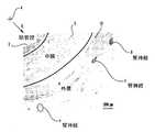
他の損傷を生じることなくこのタスクを達成することに関連する困難さを説明するために、腎動脈及び腎神経の解剖学的構造がここに記載されている。図1に示されたものが、腎臓6に接続された腎動脈10を囲む腎神経8の図である。交感腎神経8は、腎臓6から脳に至る求心知覚腎神経及び脳から腎臓6に至る遠心交感腎神経の両方を含む。更に、図2は、腎動脈の断面を示している。腎動脈壁は、内皮細胞の内側単一層を含む内膜3、動脈壁の中心にある中膜5、及び外側層である外膜4の層を含む。腎動脈10の表面上に及び腎動脈10に隣接して、外膜4内に存在する腎神経8もまた示されている。これら2つの図から分かるように、腎神経8は腎動脈10を囲んでいる。異なる個々人では、腎動脈周辺の異なる位置に腎神経を有する。従って、腎神経は、腎動脈の中心軸Aからの異なる半径方向距離Rにて存在し、また腎動脈の外周C付近の異なる位置に存在し得る。解剖学的標識点を参照することによって腎神経の位置を決めることは実用的ではない。更に、一般的な生体内画像撮影技術を用いて各人の腎神経を位置決めすることは困難であり又は不可能である。 To illustrate the difficulties associated with accomplishing this task without causing other damage, the renal artery and renal nerve anatomy is described herein. What is shown in FIG. 1 is a diagram of the
腎神経8を位置決めしかつ標的にすることができないことは、腎動脈10を損傷させることなく又は他の副作用を生じることなく交感腎神経活性を切断することを困難にしている。例えば、腎神経へエネルギーを適用する試みは、狭窄症、内膜過形成、及び壊死などのような影響を生じ得る。他の副作用としては、血栓症、血小板凝固、フィブリン血栓及び血管収縮などが挙げられる。更には、腎神経8を位置決めしかつ標的にすることができないことは、許容される治療の処置を達成するために、交感腎神経活性が十分に断絶されたことを確実にすることを困難にしている。 The inability to position and target the
特許文献1は、腎動脈内に挿入されるカテーテルに接続された高周波(「RF」)エミッターの使用を提案している。RFエミッターは内膜に対して配置されて、エミッターのすぐ近くにある腎神経の活性を低減させる温度に腎神経を加熱するように、RFエネルギーが放射される。腎動脈を取り囲むすべての腎神経を処置するために、RFエミッター源は、それぞれの腎動脈の内側周辺に複数回にわたって配置されなくてはならない。エミッターがいくつかの腎神経を見逃して、治療が不完全になることもある。更に、腎神経を加熱することを可能にするために、RFエネルギー源は内膜に接触しなければならず、これが単一層の内皮及び内膜層への損傷又は壊死を引き起こすことがあり、そして内膜過形成、腎動脈狭窄症、及び腎動脈解離を引き起こす可能性がある。 U.S. Patent No. 6,057,077 proposes the use of a radio frequency ("RF") emitter connected to a catheter that is inserted into the renal artery. The RF emitter is placed against the intima and RF energy is emitted to heat the renal nerve to a temperature that reduces the activity of the renal nerve in the immediate vicinity of the emitter. In order to treat all renal nerves surrounding the renal arteries, the RF emitter source must be placed multiple times around the inner periphery of each renal artery. The emitter may miss some renal nerves, resulting in incomplete treatment. Furthermore, in order to be able to heat the renal nerve, the RF energy source must contact the intima, which can cause damage or necrosis to a single layer of endothelium and intima and Can cause intimal hyperplasia, renal artery stenosis, and renal artery dissection.
特許文献1は、腎神経を非活性化するために、高強度集束超音波の使用も提案している。記載された高強度集束された超音波エネルギー源は、腎動脈の軸の周囲360°パターンで超音波エネルギーを放射し、内膜3に接触させる必要がない。しかし、高強度集束超音波は、動脈を囲む薄い焦点リング内に集中したエネルギーを加える。現在の技術では、腎神経を視覚化及び標的化することは困難又は不可能であるため、そして腎神経が腎動脈の中心軸から異なる半径方向の距離にて存在する可能性があるため、この薄いリングを腎神経に合わせることは困難であり又は不可能である。後者の問題は、形状又は厚さで大きな変動を備えた腎動脈を有するような患者では深刻である。更には、薄い焦点リングは、神経及び動脈の長手方向に沿ったそれぞれの腎神経の小断片のみを包含する。神経は再生する傾向があるために、小さい処置区画は、より短期間で神経が再接続することを許す。
長年にわたって、超音波は細胞修復を促進し、骨細胞の成長を刺激し、特定の組織への薬剤の供給を増強し、及び体内の組織を撮像するために用いられてきた。更には、高強度集束超音波は、体内の組織及び腫瘍の加熱及び切除のために用いられてきた。放射された超音波エネルギーは特定の位置に集束されて、超音波エネルギーが通り抜けなければならない周囲組織及び介在構造体に影響を及ぼすことなく正確かつ綿密な組織壊死を与えるので、組織の切除は、高密度焦点式超音波によりほぼ独占的に実行されてきた。 Over the years, ultrasound has been used to promote cell repair, stimulate bone cell growth, enhance drug delivery to specific tissues, and image tissues in the body. Furthermore, high intensity focused ultrasound has been used for heating and ablating tissue and tumors in the body. Since the emitted ultrasonic energy is focused at a specific location and gives accurate and precise tissue necrosis without affecting the surrounding tissue and intervening structures through which the ultrasonic energy must pass, It has been performed almost exclusively by high-density focused ultrasound.
特許文献2には、組織を切除するために、高密度焦点式超音波ではなく高度に視準を合わせた超音波エネルギーを利用して、心臓への電気信号の伝達を阻止するために、肺静脈内に傷跡の輪を生成する技術が記述されている。 In US Pat. No. 6,057,034, a highly collimated ultrasound energy is used to ablate tissue to prevent transmission of electrical signals to the heart. A technique for creating a ring of scars in a vein is described.
特許文献3では、その開示は参照により本明細書に組み込まれるが、僧帽弁逆流の治療に非集束超音波を利用する。特許文献3では、僧帽弁輪に付随するコラーゲンを加熱及び縮小するために非集束超音波エネルギーを利用する。この装置は、正確な位置に超音波振動子を配置して僧帽弁輪を標的にするために、膨張式バルーンを利用する。この装置では、バルーンの一部は加熱された組織に接触する。 In U.S. Patent No. 6,057,027, the disclosure of which is incorporated herein by reference, it utilizes unfocused ultrasound to treat mitral regurgitation. U.S. Patent No. 6,057,051 utilizes unfocused ultrasonic energy to heat and shrink the collagen associated with the mitral annulus. This device utilizes an inflatable balloon to target the mitral annulus by placing the ultrasound transducer in the correct location. In this device, a portion of the balloon is in contact with the heated tissue.
本発明に係る第1の装置は、哺乳類対象において腎神経伝達を不活性化するための装置であって、前記哺乳類対象の腎動脈へ挿入されて非集束超音波エネルギーを伝達する超音波振動子と、前記超音波振動子に電気的に接続され、前記腎動脈を包含する少なくとも0.5cm3の衝撃容積内に、前記衝撃容積全体の腎神経伝達を不活性化するのに十分な治療レベルで印加される非集束超音波エネルギーを伝達するように、前記超音波振動子を制御する、アクチュエータと、を含む。A first device according to the present invention is a device for inactivating renal nerve transmission in a mammalian subject, wherein the ultrasonic transducer is inserted into the renal artery of the mammalian subject and transmits unfocused ultrasonic energy. And a therapeutic level sufficient to inactivate renal neurotransmission of the entire impact volume within an impact volume of at least 0.5 cm3 electrically connected to the ultrasound transducer and encompassing the renal artery And an actuator for controlling the ultrasonic transducer to transmit the unfocused ultrasonic energy applied at.
上記装置において、前記アクチュエータは、10〜30ワットの音響出力レベルで前記非集束超音波エネルギーを10〜30秒間伝達するように、前記超音波振動子を制御することができる。 In the above apparatus, the actuator can control the ultrasonic transducer to transmit the unfocused ultrasonic energy for 10 to 30 seconds at an acoustic power level of 10 to 30 watts.
上記各装置において、前記アクチュエータは、前記腎動脈壁の温度を65℃未満に維持しながら、前記衝撃容積全体の温度が42℃超に達するように、前記超音波振動子を制御することができる。 In each of the above devices, the actuator can control the ultrasonic transducer so that the temperature of the entire impact volume reaches more than 42 ° C. while maintaining the temperature of the renal artery wall below 65 ° C. .
上記装置において、前記超音波振動子は、前記腎動脈の軸に沿った少なくとも2mmの長さに沿って前記腎神経伝達を不活性化するように、前記超音波エネルギーを伝達することができる。 In the above apparatus, the ultrasonic transducer can transmit the ultrasonic energy so as to inactivate the renal nerve transmission along a length of at least 2 mm along the axis of the renal artery.
上記いずれかの装置において、前記超音波振動子は、2〜10mmの長さを有するものとすることができる。 In any of the above devices, the ultrasonic transducer may have a length of 2 to 10 mm.
上記いずれかの装置において、遠位端部及び近位端部を有するカテーテルを更に含み、前記超音波振動子は、前記遠位端部に隣接して前記カテーテルに取り付けられ、前記カテーテルは、前記超音波振動子を前記腎動脈壁に接触せずに保持するように構成及び配置されるものとすることができる。 Any of the above devices further comprising a catheter having a distal end and a proximal end, wherein the ultrasonic transducer is attached to the catheter adjacent to the distal end, The ultrasonic transducer may be configured and arranged so as to hold without contacting the renal artery wall.
上記いずれかの装置において、遠位端部及び近位端部を有するカテーテルを更に含み、前記超音波振動子は、前記遠位端部に隣接して前記カテーテルに取り付けられ、前記超音波振動子は軸を有し、前記カテーテルは、前記腎動脈の軸と略平行に前記超音波振動子の軸を保持するように構成及び配置され、前記超音波振動子は、前記超音波振動子の軸の周囲360度の円筒形態で前記超音波エネルギーを伝達するものとすることができる。 Any of the above devices further comprising a catheter having a distal end and a proximal end, wherein the ultrasound transducer is attached to the catheter adjacent to the distal end, and the ultrasound transducer Has an axis, and the catheter is constructed and arranged to hold the axis of the ultrasonic transducer substantially parallel to the axis of the renal artery, and the ultrasonic transducer is an axis of the ultrasonic transducer The ultrasonic energy may be transmitted in the form of a cylinder having a 360-degree circumference.
上記いずれかの装置において、前記カテーテルは、前記超音波振動子に近接する中心配置要素を含み、前記中心配置要素は、前記腎動脈の略中心に前記超音波振動子を保持するように構成されるものとすることができる。 In any of the above devices, the catheter includes a central arrangement element proximate to the ultrasonic transducer, and the central arrangement element is configured to hold the ultrasonic transducer at a substantially center of the renal artery. Can be.
上記いずれかの装置において、前記超音波振動子はさらに、超音波エネルギーを受信して、前記受信した超音波エネルギーを表す信号を生成し、前記アクチュエータはさらに、前記治療レベル未満のレベルで測定用超音波エネルギーを伝達するように前記超音波振動子を制御し、反射された測定用超音波エネルギーを表すエコー信号を前記超音波振動子から受信し、前記受信したエコー信号を解析し、前記受信したエコー信号に基づいて前記腎動脈のサイズを決定するものとすることができる。 In any one of the above devices, the ultrasonic transducer further receives ultrasonic energy and generates a signal representing the received ultrasonic energy, and the actuator is further for measurement at a level below the treatment level. The ultrasonic transducer is controlled to transmit ultrasonic energy, and an echo signal representing the reflected ultrasonic energy for measurement is received from the ultrasonic transducer, the received echo signal is analyzed, and the reception The size of the renal artery can be determined based on the echo signal.
上記装置において、前記超音波システムは、前記腎動脈の決定サイズに応じ、治療効果のある前記非集束超音波エネルギーを伝達するのに用いられる音響出力を変えるよう、前記超音波振動子を制御するものとすることができる。 In the above apparatus, the ultrasound system controls the ultrasound transducer to vary the acoustic power used to transmit the therapeutically unfocused ultrasound energy according to the determined size of the renal artery. Can be.
上記いずれかの装置において、前記衝撃容積は、略円筒状であり、前記腎動脈と略同軸であるものとすることができる。 In any of the above devices, the impact volume may be substantially cylindrical and substantially coaxial with the renal artery.
上記いずれかの装置において、前記衝撃容積(V)は、以下の式によって決定される、請求項1から11のいずれかに記載の装置。
式:V=πr22h−πr12h(r1は前記振動子の半径、r2は前記衝撃領域の半径、hは前記振動子の長さ)12. The apparatus according to
Formula: V = πr22 h−πr12 h (r1 is the radius of the vibrator, r2 is the radius of the impact region, and h is the length of the vibrator)
本発明に係る第2の装置は、哺乳類対象において腎神経伝達を不活性化するための装置であって、超音波振動子と、前記超音波振動子に電気的に接続されるアクチュエータと、を備え、当該超音波振動子は、前記哺乳類対象の腎動脈へ挿入され、治療用量の非集束超音波エネルギーと、前記腎動脈のピングのための低出力超音波エネルギーとを伝達し、前記ピングによって前記腎動脈壁で反射されるエコー信号を生成するように構成され、前記アクチュエータは、前記腎動脈を包含する少なくとも0.5cm3の衝撃容積内に、当該腎動脈の内面を損傷させることなく、前記衝撃容積全体の腎神経伝達を不活性化するために、治療用量の非集束超音波エネルギーを伝達するように、前記超音波振動子を制御し、前記ピングのための前記低出力レベルの超音波エネルギーを伝達するように,前記超音波振動子を制御し、前記非集束超音波エネルギーの治療用量を調整するように前記エコー信号を受信するように構成されている。A second device according to the present invention is a device for inactivating renal nerve transmission in a mammalian subject, comprising: an ultrasonic transducer; and an actuator electrically connected to the ultrasonic transducer. The ultrasonic transducer is inserted into the renal artery of the mammalian subject and transmits a therapeutic dose of unfocused ultrasonic energy and low power ultrasonic energy for pinging the renal artery, Configured to generate an echo signal reflected from the renal artery wall, wherein the actuator is within an impact volume of at least 0.5 cm3 including the renal artery without damaging the inner surface of the renal artery, Control the ultrasound transducer to deliver a therapeutic dose of unfocused ultrasound energy to inactivate renal neurotransmission throughout the shock volume, and the low power for the ping To transmit ultrasonic energy of the bell, the controls ultrasonic transducer is configured to receive the echo signals to adjust the therapeutic dose of the non-focused ultrasound energy.
上記第2の装置においては、前記エコー信号に基づいて前記治療用量を決定する解析部をさらに備えているものとすることができる。 The second apparatus may further include an analysis unit that determines the treatment dose based on the echo signal.
上記第2の装置において、前記解析部は、前記ピングのための前記振動子の作動と、前記エコー信号の返送と、の間の時間遅延を測定するように構成されているものとすることができる。 In the second apparatus, the analysis unit is configured to measure a time delay between the operation of the vibrator for the ping and the return of the echo signal. it can.
上記第2の装置において、前記解析部は、前記時間遅延と前記治療用量との関係を示すルックアップテーブルを用いることで、前記治療用量を決定するように構成されているものとすることができる。 In the second apparatus, the analysis unit may be configured to determine the treatment dose by using a look-up table indicating a relationship between the time delay and the treatment dose. .
本発明の一つの態様は、ヒト又はヒト以外の哺乳類対象において腎神経伝達を不活性化するための装置を提供する。本発明のこの態様による装置は、哺乳類対象の腎動脈への挿入に適した超音波振動子を含むことが好ましい。超音波振動子は、非集束超音波エネルギーを伝達するように構成されることが好ましい。本発明のこの態様に従う装置は、振動子に電気的に接続されたアクチュエータをさらに含むことが好ましい。アクチュエータは、腎動脈を包含する少なくとも約0.5cm3の衝撃容積内に、衝撃容積全体の腎神経伝達を不活性化するのに十分な治療レベルである非集束超音波エネルギーを伝達するように超音波振動子を制御できることが最も好ましい。さらに後述するように、このような治療レベルは、組織切除に要求される以下のレベルである。One aspect of the invention provides a device for inactivating renal neurotransmission in a human or non-human mammalian subject. The device according to this aspect of the invention preferably includes an ultrasound transducer suitable for insertion into a renal artery of a mammalian subject. The ultrasonic transducer is preferably configured to transmit unfocused ultrasonic energy. The device according to this aspect of the invention preferably further comprises an actuator electrically connected to the transducer. The actuator transmits unfocused ultrasound energy at a therapeutic level sufficient to inactivate renal neurotransmission of the entire impact volume within an impact volume of at least about 0.5 cm3 that encompasses the renal artery. Most preferably, the ultrasonic transducer can be controlled. As will be described further below, such treatment levels are the following levels required for tissue ablation.
装置は、遠位端部及び近位端部を有するカテーテルをさらに含むことができ、振動子は、遠位端部に隣接してカテーテルに取り付けられ、カテーテル及び振動子は、超音波振動子が腎動脈内に配置された際に、腎動脈を通って血流が十分に流れることができるように構成及び配置される。カテーテルは、振動子を腎動脈壁に接触せずに保持するように構成及び配置され得る。カテーテルは、遠位端部に隣接して取り付けられたバルーン、ワイヤバスケットなどの膨張要素を有し得る。例えば、振動子は、振動子の軸の周囲360度の円筒型で超音波エネルギーを伝達するように構成されることができ、カテーテルは、腎動脈の軸と略平行に振動子の軸を保持するように構成及び配置されることができる。 The apparatus can further include a catheter having a distal end and a proximal end, wherein the transducer is attached to the catheter adjacent to the distal end, and the catheter and transducer are ultrasonic transducers. When placed in the renal artery, it is constructed and arranged to allow sufficient blood flow through the renal artery. The catheter may be configured and arranged to hold the transducer without contacting the renal artery wall. The catheter may have an inflation element such as a balloon, wire basket, etc. attached adjacent to the distal end. For example, the transducer can be configured to transmit ultrasonic energy in a 360 degree cylindrical shape around the transducer axis, and the catheter holds the transducer axis substantially parallel to the renal artery axis. Can be configured and arranged.
本発明の他の態様は、哺乳類対象において腎神経伝達を不活性化するための方法を提供する。本発明のこの態様による方法は、対象の腎動脈内に超音波振動子を挿入し、振動子を作動させることにより、腎動脈を包含する少なくとも約0.5cm3の衝撃容積内に、治療効果のある非集束超音波エネルギーを伝達するステップを含むことが好ましい。超音波エネルギーは、衝撃容積内の全ての腎神経伝達を不活性化するのに十分な治療効果のある非集束超音波エネルギーであることが好ましい。例えば、振動子を作動させるステップでは、衝撃容積内の腎神経を含む固形組織を42℃超に加熱しながら、腎動脈壁の温度を65℃未満に維持し得る。Another aspect of the invention provides a method for inactivating renal neurotransmission in a mammalian subject. The method according to this aspect of the invention provides a therapeutic effect within an impact volume of at least about 0.5 cm3 that includes the renal artery by inserting an ultrasonic transducer into the subject's renal artery and activating the transducer. Preferably, the method includes transmitting certain unfocused ultrasound energy. The ultrasound energy is preferably unfocused ultrasound energy that has a therapeutic effect sufficient to inactivate all renal neurotransmission within the shock volume. For example, in the step of actuating the transducer, the temperature of the renal artery wall may be maintained below 65 ° C. while heating the solid tissue including the renal nerve in the impact volume to above 42 ° C.
衝撃容積が比較的大きく、そして好ましくは衝撃容積全体の組織が神経伝達を不活性化するのに十分な温度に達するので、本発明のこの態様に従う好ましい方法は、腎神経の実際の位置を測定することや、腎神経に標的を合わせたり焦点を当てたりすることなしに、首尾よく実行されることができる。この治療は、組織の温度を測定せずに実行されることができる。さらに、好ましくはこの治療は、腎動脈の狭窄症、内膜過形成、又は医師の介入が必要な他の損傷を引き起こさずに実行されることができる。好ましい方法及び装置では、不活性化部分に沿って伝達を回復する神経回復の可能性を低減するために、腎神経の比較的長い部分を不活性化することができる。 The preferred method according to this aspect of the invention measures the actual location of the renal nerve, since the impact volume is relatively large, and preferably the tissue of the entire impact volume reaches a temperature sufficient to inactivate neurotransmission. Can be performed successfully without having to do or target or focus on the renal nerve. This treatment can be performed without measuring the temperature of the tissue. Furthermore, preferably the treatment can be performed without causing renal artery stenosis, intimal hyperplasia, or other damage requiring physician intervention. In preferred methods and devices, a relatively long portion of the renal nerve can be inactivated to reduce the chance of nerve recovery to restore transmission along the inactivated portion.
本発明の更なる態様は、前述の方法及び装置に用いられ得るプローブ、並びに前述の方法ステップを実行するための手段を組み込んだ装置を提供する。 Further aspects of the invention provide probes that can be used in the methods and apparatus described above, as well as devices incorporating means for performing the method steps described above.
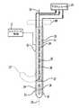
本発明の一つの実施形態に従う装置(図3)は、シース12を含む。シース12は、近位端部14、遠位端部16及び近位遠位軸15を有する概して伸長管の形状にできる。身体に挿入する伸長要素に関連して本開示に用いられる用語「遠位」は、身体に最初に挿入される端部、すなわち身体内で前進中の要素の先端を意味し、一方、用語「近位」は、それとは反対端を意味する。シース12は可動シースでもよい。そのために、シースは、その近位端部と遠位端部との間を延伸しかつ配置されたステアリング制御17と接続する1つ以上のプルワイヤ(不図示)などの周知の要素を含むことができ、操作者がステアリング制御を作動することで、軸15を横切る方向にシースの遠位端部16を曲げることができる。 An apparatus (FIG. 3) according to one embodiment of the present invention includes a
装置は、近位端部20、遠位端部22及び近位遠位軸を有するカテーテル18をさらに含み、図3に示す状況では、近位遠位軸は、シースの近位遠位軸15と同じ位置にある。カテーテルの近位端部20は、トルクを伝達できるように比較的堅いことが好ましい。それ故、カテーテル18の近位端部20を回転させることにより、カテーテル18の遠位端部22は、カテーテル18の近位遠位軸の周りを回転する。 The apparatus further includes a
カテーテル18の遠位端部22は、それがシース12の外側に出た時に、図3の破線22'に示すかぎ状になるように形成される。この状態では、遠位端部22'の回転運動により、近位遠位軸の周りを湾曲部が回転する。そのため、カテーテル18の近位端部を回転させることにより、カテーテル18の遠位端部22'は、任意の半径方向に配置され得る。 The
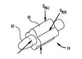
カテーテル18は、遠位端部22に取り付けられたバルーン24を有する。バルーン24は、膨張状態(図4)において非円形の輪郭を有し、部分82は直径において腎動脈よりも小さく、別の部分80は形状において非円形である。非円形な部分の最大直径DMAJは、腎動脈の内径と等しいか、又はそれよりもわずかに小さく、最小直径DMINは、最大直径よりも小さい。The
超音波振動子30(図3及び図5)が、バルーン24内においてカテーテル18の遠位端部22に隣接して取り付けられる。振動子30は、セラミック圧電材料から形成されることが好ましく、チューブ状であり、振動子30の近位遠位軸33の周りを回転する柱面状の外側放射面31を有する。軸31に沿った振動子30の軸の長さは、通常、約2〜10mmであり、6mmであることが好ましい。振動子30の外径は、その直径が約1.5〜3mmであり、2mmであることが好ましい。振動子の物理的構造及びそのカテーテルへの取り付け方法は、例えば、米国特許第7,540,846号及び第6,763,722号に記述されており、その開示の全体は参照により本明細書に組み込まれる。振動子30は、その内面及び外面に導電被覆(不図示)を更に有する。それ故、振動子は、金属支持管84(図5)に物理的に取り付けられ、そして金属支持管84は、カテーテルに取り付けられることができる。被覆は、アース端子及び信号線32に電気的に接続される。線32は、振動子30から管腔34を通り抜けて延伸する。管腔34は、カテーテル18の
近位端部と遠位端部との間を延伸し、線32は、振動子30から管腔34を通り抜けて、カテーテル18の近位端部14まで延伸する。An ultrasonic transducer 30 (FIGS. 3 and 5) is mounted in the
振動子30は、その内部で生成される超音波エネルギーが主に外側放射面から放射されるようにできている。そのため、振動子は、その内側に向かう超音波エネルギーを反射するようにされた特徴を含むことができ、反射したエネルギーは、外面における超音波振動を強める。例えば、振動子30の内面が、隙間(不図示)によって、金属で形成された支持管の外面と離されて、支持管84及び振動子30は配置される。振動子の内面と支持管の外面との間の隙間の距離は、振動子30の効率的な作動を促進するように、振動子が放射する超音波エネルギーの波長の半分であってもよい。この実施形態では、振動子30が生成する超音波エネルギーは、水分が存在する隙間において反射して、振動子30からの超音波エネルギーの伝播を増強し、超音波エネルギーが、振動子30の外面から外側に確実に向けられる。 The
振動子30はまた、外面31に作用する超音波を、線32を通る電気信号に変換するようにも設計される。別の言い方をすれば、振動子30は、超音波エミッター又は超音波受信部のいずれの機能も果たすことができる。 The
振動子30は、例えば、約1MHz〜数十MHz、通常は約9MHzの周波数で作動するように設計される。振動子30の実際の周波数は、通常、製作公差に応じて多少異なり得る。振動子の最適な作動周波数は、カテーテルに取り付けられたデジタルメモリ、バーコードなどの機械可読な又は人間が解読可能な要素(不図示)によりエンコードされ得る。あるいは、可読要素は、製造番号又は個々のカテーテルを識別する他の情報をエンコードすることにより、最適な作動周波数が、インターネットなどの通信リンクを通じてアクセス可能な中央データベースから検索され得る。 The
本明細書においてアクチュエータとも呼ばれる超音波システム20は、プラグコネクタ88(図3)を通じてカテーテル18及び振動子30に取り外し可能に接続される。図6に示すように、超音波システム20は、ユーザインターフェース40、プログラマブルマイクロプロセッサ(不図示)などのプログラマブル制御装置を内蔵する制御盤42、超音波励振源44、及び循環装置48を含むことができる。ユーザインターフェース40は、励振源44と相互作用する制御盤42と相互作用することにより、振動子の最適な作動周波数を、電気信号線32を通じて振動子30に送信する。制御盤42及び超音波源44は、電気信号の振幅及びタイミングを制御し、振動子30が生成する超音波信号の出力レベル及び持続期間を制御するように設計される。励振源44はさらに、振動子30によって生成されて線32に生じる電気信号を検出し、このような信号を制御盤42に伝達するように設計される。 The
循環装置48は、カテーテル18内の管腔(不図示)に接続され、そして管腔はバルーン24に接続される。循環装置は、液体、好ましくは水性液体を、カテーテル18を通じてバルーン24内の振動子30に循環するために配置される。循環装置48は、循環冷却剤35、ポンプ37、冷凍コイル(不図示)などを保持するタンクなどの要素を含むことができ、好ましくは体温未満に制御した温度の液体を、バルーン24の内部空間に供給する。制御盤42は、循環装置48と相互作用し、バルーン24に出入りする液体の流れを制御する。例えば、制御盤42は、ポンプ37の作動速度を制御するために、ポンプに用いられる駆動モータに結合するモータ制御装置を含むことができる。このようなモータ制御装置は、例えば、ポンプ37が蠕動ポンプなどの容積型ポンプである場合に用いられ得る。代替的に又は追加的に、制御回路は、流量に関して回路抵抗を変えるために、流体回路に接続された制御可能弁などの構造(不図示)を含んでもよい。超音波システム20は、2つの圧力センサ38をさらに含み、カテーテル18内の液体の流れを監視し得る。一
方の圧力センサが、カテーテル18の遠位に流れる液体を監視して閉塞があるか否かを判定し、他方が、カテーテル18における液漏を監視する。バルーンが膨張状態にある間は、圧力センサ38は、バルーン内を所望の圧力、好ましくは約3ポンド/平方インチ(20KPa)に維持する。The
超音波システム20は、カテーテル18における機械可読の要素を読み取り、このような要素からの情報を制御盤46に伝える読取装置46を内蔵する。前述のように、カテーテルにおける機械可読の要素は、個々のカテーテル18における振動子30の作動周波数などの情報を含むことができ、制御盤42はこの情報を用いて、振動子を励起するための適切な周波数を設定できる。あるいは、制御盤は、励振源44を作動させて振動子に低出力レベルのエネルギーを供給し、同時に、例えば8.5Mhz〜9.5Mhzの既定範囲の周波数を超えた励起周波数を走査し、このような励起に対する振動子の反応を監視することによって振動子の作動周波数を測定するように構成されることができる。 The
超音波システム20は、米国仮特許出願第61/256002号(2009年10月29日出願)である発明の名称「METHOD AND APPARATUS FOR PERCUTANEOUS TREATMENT OF MITRAL VALVE REGURGITATION (PMVR)」に開示されているものに類似するものでもよく、その開示は参照により本明細書に組み込まれる。 The
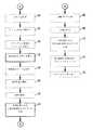
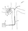
本発明の実施形態に従う方法を、図7のフローチャートに示す。患者などのヒト又はヒト以外の哺乳類対象を前処理し(ステップ50)、次に、大腿動脈上の位置などの動脈のアクセス部位を前処理し(ステップ52)、カテーテル18と超音波システム20とを接続し(ステップ54)、大動脈内のアクセス部位を通じてシース12の遠位端部を挿入することにより、腎動脈内に超音波振動子30を挿入する(ステップ56)。シースの遠位端部が大動脈内に位置している間、図8に概略を示すように、カテーテルの遠位端部がシースから突き出るまで、カテーテル18はシース内を前進する。カテーテル18の遠位端部22があらかじめかぎ状に形成されるため、先端が腎動脈10の分岐を向くように大動脈の内部で回転し、その後、前方及び後方にわずかに押し引きされると、カテーテル18の遠位端部22は、腎動脈10内に滑り込むことができる。この作用は、腎動脈/大動脈分岐が標準的な角度で位置するときにより容易になる。カテーテル18の遠位端部22はかぎ状であるため、大動脈内で引き戻されると、腎動脈10の側枝を捕える傾向がある。
カテーテルにおけるバルーン24は、カテーテルの遠位端部が腎動脈内の所望の位置に配置されるまで収縮状態を維持することが好ましい。カテーテル18及び振動子30の挿入中(ステップ56)、医師は、腎臓6又は存在するであろう腎動脈10のあらゆる分岐の前であっても、腎動脈10内での振動子30の配置を確認できる。このような確認は、蛍光透視法などのX線技術を利用して実現され得る。A method according to an embodiment of the invention is shown in the flowchart of FIG. A human or non-human mammalian subject, such as a patient, is pre-processed (step 50), and then an arterial access site, such as a location on the femoral artery, is pre-processed (step 52), the
The
カテーテルの遠位端部が腎動脈内に配置されると、ポンプ37はバルーン24を、図4及び図5に示すような膨張状態にする。この状態では、バルーンの非円形部80が動脈壁に係合するため、振動子30は腎動脈内の中心に位置し、振動子の軸33(図5)は腎動脈の軸Aとほぼ同軸上に配置される。ただし、バルーンは腎動脈内の血流を妨げない。この状況では、循環装置48は、バルーン24に出入りする冷却された水性液体の流れを維持することにより、振動子30を冷却する。冷却されたバルーンはさらに、腎動脈の内面を冷却する傾向がある。腎動脈を流れる継続的な血流が、腎動脈の内面をさらに冷却する。バルーン内を流れる液体はX線造影剤を含んでもよく、これはバルーンの可視化及び適切な配置の確認に役立つ。 When the distal end of the catheter is placed in the renal artery, the
次のステップ58では、超音波システム20は、振動子30を利用して腎動脈10のサイズを測定する。制御盤42及び超音波源44は振動子30を作動させて、低出力の超音波パルスを利用して腎動脈10を「ピング」(調査)する。この超音波パルスは、エコーとして動脈壁で振動子30に反射される。振動子30は、エコーを線32を通る信号に変換する。超音波システム20は、次に、エコー信号を解析して動脈10のサイズを決定する。例えば、超音波システム20は、「ピング」(調査用の超音波パルス)を生成するための振動子の作動と、エコー信号の返送との間の時間遅延を測定できる。ステップ60では、超音波システム20は、測定した動脈サイズを用いて、後のステップで治療用の超音波エネルギーを加える間に振動子30が供給する音響出力を設定する。例えば、制御盤42は、特定のエコー遅延(したがって動脈直径)と特定の出力レベルとの相関関係を示すルックアップテーブルを利用し得る。通常、動脈直径がより大きいと、当然ながら用いる出力もより大きくなる。腎動脈10の形状の変化又は振動子30の中心位置の変化は、エ
コー信号における時間遅延の幅をもたらすことがある。超音波システム20は、その幅の平均を取得して腎動脈10の平均サイズを決定し、その平均サイズに基づいて出力レベルを調節できる。In the
医師は次に、ユーザインターフェース40を通して治療を開始する(ステップ60)。この治療(ステップ64)では、超音波システム又はアクチュエータ20、特に制御盤42及び超音波源44が、振動子30を作動させて、治療効果のある超音波を衝撃容積11(図5)に伝達する。振動子30が伝達する超音波エネルギーは、概ね半径方向外向きに振動子30から離れて伝播し、完全な円、又は振動子30の近位遠位軸33及び腎動脈の軸Aの周りの360度の孤を包含する。 The physician then initiates treatment through the user interface 40 (step 60). In this treatment (step 64), the ultrasound system or
超音波振動子30の選択された作動周波数、非集束特性、配置、サイズ、及び形状に応じて、腎動脈10及び腎神経の全体を、振動子30の「近傍」領域内に配置することができる。外向きに広がるこの領域内では、振動子30が生成する非集束超音波の全方向(360度)への円筒形ビームは視準を維持する傾向があり、その軸の長さは、振動子30の軸の長さにほぼ等しい。円筒振動子における近傍領域の半径範囲は、式L2/λにより定義される。この式において、Lは振動子30の軸の長さであり、λは超音波の波長である。L2/λよりも大きい振動子30の表面からの距離では、ビームは、かなりの程度まで軸方向に広がり始める。ただし、L2/λよりも短い距離では、ビームは、実質的には軸方向に広がらない。それ故、近傍領域内において、L2/λよりも短い距離では、非集束ビームが半径方向に広がるにつれて、超音波エネルギーの強度は、振動子30の表面からの距離に比例して直線的に減少する。本開示での使用において、用語「非集束」は、振動子30から離れるビームの伝播方向において強度が増大しないビームを意味する。Depending on the selected operating frequency, unfocusing characteristics, placement, size, and shape of the
衝撃容積11は略円筒状であり、腎動脈と同軸である。衝撃容積11は、振動子の表面から衝撃半径39まで広がるが、衝撃半径39では、超音波エネルギーの強度は小さ過ぎて、腎神経8を不活性化するほどの温度範囲に組織を加熱しない。衝撃半径39は、振動子30が伝達する超音波エネルギー量に応じて決まる。衝撃容積11の容積Vは、以下の方程式で求められる。
V=πr22h−πr12h
ここで、r1は振動子30の半径であり、r2は衝撃領域11の半径であり、hは振動子30の長さである。The
V = πr22 h−πr12 h
Here, r1 is the radius of the
前述のように、振動子30の長さは2mm〜10mmの範囲で異なり得るが、腎神経の不活性帯を広くするために6mmが好ましい。振動子30の直径は、1.5mm〜3.0mmの範囲で異なり得るが、2.0mmが好ましい。エネルギー量は、その治療効果に加え、腎動脈10を越えた構造に損害を与える超音波エネルギーを伝達することなく、その全ての平均半径が3〜4mmである腎動脈10及び隣接する腎神経を包含するために、衝撃容積11の半径39を好ましくは5mm〜7mmの範囲にできるようにも選択される。これにより、衝撃容積11は少なくとも0.5cm3となり、腎神経の不活性部分の長さは、振動子32の長さとほぼ一致する。As described above, the length of the
出力レベルは、衝撃容積全体の固形組織が、数秒間以上、約42℃以上に加熱されるが、腎動脈の内膜層を含む固形組織の全てが65℃未満に維持されるように選択されることが好ましい。それ故、衝撃域全体にわたって、固形組織(腎神経の全てを含む)は、神経伝達を不活性化するのに十分であるが、急速な組織壊死を引き起こさない温度に維持される。 The power level is selected so that the solid tissue of the entire impact volume is heated to about 42 ° C or higher for a few seconds or more, but all of the solid tissue including the intimal layer of the renal artery is maintained below 65 ° C. It is preferable. Therefore, throughout the shock zone, solid tissue (including all of the renal nerves) is maintained at a temperature that is sufficient to inactivate neurotransmission but does not cause rapid tissue necrosis.
神経損傷は、組織壊死よりも非常に低い温度で、かつ非常に急速に発生することを研究は示している。Bunch, Jared. T.他による、「Mechanisms of Phrenic Nerve Injury During Radiofrequency Ablation at the Pulmonary Vein Orifice」,Journal of Cardiovascular Electrophysiology,第16巻、第12版、1318〜1325ページ(2005年12月8日)を参照されたい。その内容は、参照により本明細書に組み込まれる。組織壊死は、通常、65℃以上の温度に約10秒間以上さらされた場合に引き起こされ、一方、腎神経8の不活性化は、通常、それらが42℃以上の温度に数秒間以上さらされた場合に引き起こされる。このため、超音波エネルギー量は、衝撃容積11をそれらの間の温度に数秒間以上維持する量が選択される。超音波エネルギー量はまた、衝撃容積内のコラーゲンの相当量を減少しない程度に少量であることが好ましい。振動子の作動にはそれ故、狭窄症、内膜過形成、内膜壊死、又は医師の介入が必要な他の負傷などの損傷を腎動脈10にもたらすことなく、腎神経8を不活性化する治療用量が供給される。腎動脈10壁の内側を流れる継続的な血流は、腎動脈の層3(図2)を確実に冷却する。これにより、伝達される治療用量で伝達された超音波エネルギーは放散され、内膜層3でなく、主に腎動脈10の外層で熱に変換される。さらに、振動子30を備えたバルーン24を流れる冷却液体の循環が、振動子30から、内膜層3及び振動子を通り過ぎて流れる血液に移動する熱を減少する効果もある。したがって、伝達される治療用の非集束超音波エネルギーは、内膜層を損傷せず、さらには血栓形成を招かない、より安全な治療を提供する。 Studies have shown that nerve damage occurs at a much lower temperature and more rapidly than tissue necrosis. Bunch, Jared. T.A. Others, “Mechanisms of Phrenic Nerve Injury Durating Radiofrequency Ablation at the Pulmonary Vein Orifice”,
治療用量の超音波エネルギーを生成するための振動子30の音響出力は、通常は約10〜約100ワットであり、より通常では、約20〜約30ワットである。適用される出力の持続期間は、通常、約2秒〜約1分以上であり、より通常では、約10秒〜約20秒である。所望の温度レベルを達成するための、特定のシステムに用いられる最適なエネルギー量は、数学モデル化又は動物試験により決定され得る。 The acoustic power of
非集束超音波エネルギーのための衝撃容積11は、外膜及び近接する周囲組織を含む腎動脈10全体を包含し、したがって、腎動脈周囲の腎神経のすべてを包含する。そのため、振動子30の腎動脈10内での配置は、対象の腎動脈10周囲の全ての腎神経8の伝達を不活性化するような無差別な配置となる。本開示で用いられる「無差別な」及び「無差別に」は、任意の特定の腎神経に標的を合わせたり、それを位置決めしたり、それに焦点を当てたりしないことを意味する。 The
任意で、医師は次に、腎動脈に沿ってカテーテル18及び振動子30を再配置し(ステップ66)、治療を再開し68、治療効果のある非集束超音波エネルギーを再伝達し得る(ステップ70)。これにより、腎動脈の長さ方向に沿った更なる位置で腎神経が不活性化され、安全かつより信頼できる治療を提供できる。再配置及び再送信ステップは、任意で複数回実行されてもよい。医師は次に、振動子30を含むカテーテル18を他の腎動脈10に動かし、その動脈10の完全な治療を再度実行する(ステップ72)。治療の終了後、カテーテル18は対象の体から取り出される(ステップ74)。 Optionally, the physician can then reposition
前述した特徴の多くの変更及び組み合わせが使用され得る。例えば、超音波システム20は振動子30を制御して、治療用の超音波エネルギーの印加の間に、超音波エネルギーをパルス関数を利用して伝達できる。パルス関数は、デューティサイクルの例えば50%で、超音波振動子30に超音波エネルギーを放射させる。超音波エネルギーのパルス変調は、長い治療時間でも、組織の温度を抑制するのに役立つ。 Many variations and combinations of the features described above can be used. For example, the
さらなる変更では、腎動脈サイズの測定ステップ、及びエネルギー量の調節ステップ(ステップ58及び72)は省略されてもよい。この例では、振動子は単に、平均的な対象の腎動脈に十分であるプリセット出力レベルにおいて作動する。さらなる変更では、腎動脈直径は、振動子30を作動させる以外の技術、例えば、腎動脈に導入される造影剤を利用したX線画像、磁気共鳴映像法、又は別個の超音波測定カテーテルを利用して測定されてもよい。この例では、個々の測定データが、エネルギー量の設定に用いられてもよい。 In a further modification, the renal artery size measurement step and the energy amount adjustment step (
前述の特定の実施形態では、振動子30は、膨張バルーン24の非円形要素80により腎動脈内の中心に配置されるが、中心に配置する他の方法を用いてもよい。例えば、振動子を取り囲む膨張バルーンは、腎動脈10より直径がわずかに小さい円形断面のバルーンにすることができる。このようなバルーンは、腎動脈10で血流を流し続けながら、振動子30を腎動脈10の略中心に維持できる。この実施形態では、バルーン24周囲の血流がバルーンを多少前後に動かすため、バルーン24は、腎動脈10に取り付けられた場合よりも動的である。この動的性質により、腎動脈10の全ての部分に血液が伝わり続けるため、内膜層3を冷却し、その損傷を最小化できる。他の実施形態では、カテーテルの遠位端部は、バルーン以外の膨張構造、例えば、軸方向に構造を圧縮することにより、半径方向の膨張状態を選択的にもたらし得るワイヤバスケット又はワイヤメッシュ構造などを含んでもよい。ワイヤバスケットは、超音波に対して無反射であっても、又は振動子30から軸方向にオフセットする位置でカテーテルに取り付けられてもよい。 In the particular embodiment described above, the
さらなる変更では、バルーン24は多孔質膜から形成されるか、又は穴を含む構造でもよく、それにより、バルーン24内を循環する冷却液体が、バルーン24内から腎動脈10内の血流内に流出し、又は排出され得る。血流に入る、バルーン24から流出した又は排出された冷却液体は、血流が接触する腎動脈10の内面をさらに冷却し得る。 In a further modification, the
通常、カテーテル18は、簡単に処分できる使い捨て可能な器具である。カテーテル18又は超音波システム20は、一度使用された後のカテーテル18の再利用を妨げる安全装置を含んでもよい。このような安全装置それ自体は、当業界で周知のものである。 Typically, the
更なる別の変更では、医師がカテーテルの遠位端部22を直接操縦可能な操縦機構を、カテーテル18それ自体が備えてもよい。シースは無くてもよい。 In yet another modification, the
別の変更として、超音波振動子30を含むカテーテル18の遠位端部におけるエネルギーエミッターユニットは、腎静脈に配置されてもよく、超音波振動子30は、超音波エネルギーを腎静脈内の振動子30から腎動脈10への望ましい方向に選択的に導くために、限定された半径方向の範囲のみで、振動子30から超音波エネルギーを選択的に方向付けるための反射又は遮断構造を含んでもよい。静脈に進入する方法が利用される場合には、振動子30の側焼成配置として周知のように、超音波エネルギーをある部分に導くか、振動子30の外面から離れる方向にビームを伝搬してもよい。例えば、超音波振動子30は、米国仮特許出願第61/256002号(2009年10月29日出願)である発明の名称「METHOD AND APPARATUS FOR PERCUTANEOUS TREATMENT OF MITRAL VALVE REGURGITATION (PMVR)」に開示されたものと同様の構成を有し、指向性超音波エネルギー5を放射するように作動するものでもよく、その開示は参照により本明細書に組み込まれる。こ
の変更では、カテーテル18が身体内に導かれ、その後、腎臓6に近接して配置される経路は、前述の心房へ近づく経路とは異なる。静脈への進入は、カテーテル18を取り出した後の閉鎖の問題を低減し得るという利点により、利用されることができる。As another modification, the energy emitter unit at the distal end of the
本発明は特定の実施形態を参照にして説明されたが、これら実施形態は、本発明の原理及び用途の単なる例示であることが理解される。従って、添付の特許請求の範囲で定義されるような本発明の精神及び範囲から逸脱することなく、例示した実施形態に多くの改良が行われ得ること、及び他の配置が考案され得ることを理解されたい。 Although the invention has been described with reference to particular embodiments, it is understood that these embodiments are merely illustrative of the principles and applications of the present invention. Accordingly, many modifications can be made to the illustrated embodiments and other arrangements can be devised without departing from the spirit and scope of the invention as defined in the appended claims. I want you to understand.
Claims (11)
Translated fromJapanese超音波振動子と、
前記超音波振動子に電気的に接続されるアクチュエータと、
前記超音波振動子を包含するように構成された拡張可能なバルーンと、
を備え、
当該超音波振動子は、前記哺乳類対象の腎動脈へ挿入され、非集束超音波エネルギーを、前記腎動脈へ伝達し、
前記アクチュエータは、当該腎動脈の内膜層を損傷させることなく、衝撃容積全体の腎神経伝達を不活性化するために、治療用量の非集束超音波エネルギーを360度の円筒形態で前記超音波振動子に伝達させ、
前記超音波振動子及び前記腎動脈の内面を冷却するために、拡張された前記バルーンを通じる冷却された液体の流れの循環を制御する冷却装置をさらに備える、装置。A device for inactivating renal neurotransmission in a mammalian subject comprising:
An ultrasonic transducer,
An actuator electrically connected to the ultrasonic transducer;
An expandable balloon configured to include the ultrasonic transducer;
With
The ultrasonic transducer is inserted into the mammalian subject renalarteries, thenon-focused ultrasound energy, and transmitted to the renal arteries,
Theactuator without damaging the inner membrane layer ofthis該腎artery, in order to inactivate renal neurotransmission entireopposition撃容product, the cylindrical form of a non-focused ultrasound energy 360 degrees therapeutic dose Transmitted to the ultrasonic transducer,
Anapparatus further comprising acooling device that controls circulation of acooled liquid flow through the expanded balloon to cool the ultrasound transducer and the inner surface of the renal artery.
前記アクチュエータはさらに、
前記超音波振動子にある測定レベルで超音波エネルギーを伝達させ、反射された測定用超音波エネルギーを表すエコー信号を前記超音波振動子から受信し、
前記受信したエコー信号を解析し、
前記受信したエコー信号に基づいて前記腎動脈のサイズを決定する、請求項1から7のいずれかに記載の装置。The ultrasonic transducer further receives ultrasonic energy and generates a signal representing the received ultrasonic energy;
The actuator further includes:
Transmitting ultrasonic energy at a measurement level in the ultrasonic transducer and receiving an echo signal representing the reflected ultrasonic energy for measurement from the ultrasonic transducer;
Analyzing the received echo signal;
The apparatus according to claim 1, wherein the size of the renal artery is determined based on the received echo signal.
式:V=πr22h−πr12h(r1は前記振動子の半径、r2は前記衝撃領域の半径、hは前記振動子の長さ)
The apparatus according to any of claims 1 to 10, wherein the impact volume (V) is determined by the following equation.
Formula: V = πr22h−πr12h (r1 is the radius of the vibrator, r2 is the radius of the impact region, and h is the length of the vibrator)
Applications Claiming Priority (4)
| Application Number | Priority Date | Filing Date | Title |
|---|---|---|---|
| US25642909P | 2009-10-30 | 2009-10-30 | |
| US61/256,429 | 2009-10-30 | ||
| US29261810P | 2010-01-06 | 2010-01-06 | |
| US61/292,618 | 2010-01-06 |
Related Parent Applications (1)
| Application Number | Title | Priority Date | Filing Date |
|---|---|---|---|
| JP2014255602ADivisionJP6412790B2 (en) | 2009-10-30 | 2014-12-17 | Method and apparatus for treating hypertension by percutaneous ultrasound renal nerve removal |
Publications (2)
| Publication Number | Publication Date |
|---|---|
| JP2017196461A JP2017196461A (en) | 2017-11-02 |
| JP6571719B2true JP6571719B2 (en) | 2019-09-04 |
Family
ID=43302706
Family Applications (3)
| Application Number | Title | Priority Date | Filing Date |
|---|---|---|---|
| JP2012537097AActiveJP5768056B2 (en) | 2009-10-30 | 2010-10-29 | Method and apparatus for treating hypertension by percutaneous ultrasound renal nerve removal |
| JP2014255602AActiveJP6412790B2 (en) | 2009-10-30 | 2014-12-17 | Method and apparatus for treating hypertension by percutaneous ultrasound renal nerve removal |
| JP2017125690AActiveJP6571719B2 (en) | 2009-10-30 | 2017-06-27 | Method and apparatus for treating hypertension by percutaneous ultrasound renal nerve removal |
Family Applications Before (2)
| Application Number | Title | Priority Date | Filing Date |
|---|---|---|---|
| JP2012537097AActiveJP5768056B2 (en) | 2009-10-30 | 2010-10-29 | Method and apparatus for treating hypertension by percutaneous ultrasound renal nerve removal |
| JP2014255602AActiveJP6412790B2 (en) | 2009-10-30 | 2014-12-17 | Method and apparatus for treating hypertension by percutaneous ultrasound renal nerve removal |
Country Status (9)
| Country | Link |
|---|---|
| US (5) | US9981108B2 (en) |
| EP (3) | EP3132828B1 (en) |
| JP (3) | JP5768056B2 (en) |
| KR (2) | KR101673574B1 (en) |
| CN (1) | CN102596320B (en) |
| AU (2) | AU2010313379B2 (en) |
| CA (1) | CA2779386C (en) |
| IL (1) | IL219252A0 (en) |
| WO (1) | WO2011053757A1 (en) |
Families Citing this family (178)
| Publication number | Priority date | Publication date | Assignee | Title |
|---|---|---|---|---|
| US8241274B2 (en) | 2000-01-19 | 2012-08-14 | Medtronic, Inc. | Method for guiding a medical device |
| US9636174B2 (en) | 2002-04-08 | 2017-05-02 | Medtronic Ardian Luxembourg S.A.R.L. | Methods for therapeutic renal neuromodulation |
| US20070135875A1 (en) | 2002-04-08 | 2007-06-14 | Ardian, Inc. | Methods and apparatus for thermally-induced renal neuromodulation |
| US20070129761A1 (en) | 2002-04-08 | 2007-06-07 | Ardian, Inc. | Methods for treating heart arrhythmia |
| US8150519B2 (en) | 2002-04-08 | 2012-04-03 | Ardian, Inc. | Methods and apparatus for bilateral renal neuromodulation |
| US20080213331A1 (en) | 2002-04-08 | 2008-09-04 | Ardian, Inc. | Methods and devices for renal nerve blocking |
| US7617005B2 (en)* | 2002-04-08 | 2009-11-10 | Ardian, Inc. | Methods and apparatus for thermally-induced renal neuromodulation |
| US20040082859A1 (en) | 2002-07-01 | 2004-04-29 | Alan Schaer | Method and apparatus employing ultrasound energy to treat body sphincters |
| US20040226556A1 (en) | 2003-05-13 | 2004-11-18 | Deem Mark E. | Apparatus for treating asthma using neurotoxin |
| DE202004021953U1 (en) | 2003-09-12 | 2013-06-19 | Vessix Vascular, Inc. | Selectable eccentric remodeling and / or ablation of atherosclerotic material |
| US8396548B2 (en) | 2008-11-14 | 2013-03-12 | Vessix Vascular, Inc. | Selective drug delivery in a lumen |
| US9713730B2 (en) | 2004-09-10 | 2017-07-25 | Boston Scientific Scimed, Inc. | Apparatus and method for treatment of in-stent restenosis |
| JP5219518B2 (en) | 2004-12-09 | 2013-06-26 | ザ ファウンドリー, エルエルシー | Aortic valve repair |
| US20070213616A1 (en) | 2005-10-20 | 2007-09-13 | Thomas Anderson | Systems and methods for arteriotomy localization |
| US8019435B2 (en) | 2006-05-02 | 2011-09-13 | Boston Scientific Scimed, Inc. | Control of arterial smooth muscle tone |
| US10499937B2 (en) | 2006-05-19 | 2019-12-10 | Recor Medical, Inc. | Ablation device with optimized input power profile and method of using the same |
| US20080039746A1 (en) | 2006-05-25 | 2008-02-14 | Medtronic, Inc. | Methods of using high intensity focused ultrasound to form an ablated tissue area containing a plurality of lesions |
| JP5559539B2 (en) | 2006-10-18 | 2014-07-23 | べシックス・バスキュラー・インコーポレイテッド | System that induces desirable temperature effects on body tissue |
| EP2076198A4 (en) | 2006-10-18 | 2009-12-09 | Minnow Medical Inc | Inducing desirable temperature effects on body tissue |
| EP2455036B1 (en) | 2006-10-18 | 2015-07-15 | Vessix Vascular, Inc. | Tuned RF energy and electrical tissue characterization for selective treatment of target tissues |
| US8119860B2 (en) | 2007-04-16 | 2012-02-21 | E. I. Du Pont De Nemours And Company | Delta-9 elongases and their use in making polyunsaturated fatty acids |
| US8483831B1 (en) | 2008-02-15 | 2013-07-09 | Holaira, Inc. | System and method for bronchial dilation |
| JP2011519699A (en) | 2008-05-09 | 2011-07-14 | インノブアトイブエ プルモナルイ ソルウトイオンス,インコーポレイティッド | Systems, assemblies and methods for treatment of bronchial trees |
| EP2355737B1 (en) | 2008-11-17 | 2021-08-11 | Boston Scientific Scimed, Inc. | Selective accumulation of energy without knowledge of tissue topography |
| WO2010080886A1 (en) | 2009-01-09 | 2010-07-15 | Recor Medical, Inc. | Methods and apparatus for treatment of mitral valve in insufficiency |
| US11998266B2 (en) | 2009-10-12 | 2024-06-04 | Otsuka Medical Devices Co., Ltd | Intravascular energy delivery |
| US8295912B2 (en) | 2009-10-12 | 2012-10-23 | Kona Medical, Inc. | Method and system to inhibit a function of a nerve traveling with an artery |
| US9119951B2 (en) | 2009-10-12 | 2015-09-01 | Kona Medical, Inc. | Energetic modulation of nerves |
| US9174065B2 (en) | 2009-10-12 | 2015-11-03 | Kona Medical, Inc. | Energetic modulation of nerves |
| US8986211B2 (en) | 2009-10-12 | 2015-03-24 | Kona Medical, Inc. | Energetic modulation of nerves |
| US8986231B2 (en) | 2009-10-12 | 2015-03-24 | Kona Medical, Inc. | Energetic modulation of nerves |
| US20160059044A1 (en) | 2009-10-12 | 2016-03-03 | Kona Medical, Inc. | Energy delivery to intraparenchymal regions of the kidney to treat hypertension |
| US20110092880A1 (en) | 2009-10-12 | 2011-04-21 | Michael Gertner | Energetic modulation of nerves |
| US20110118600A1 (en) | 2009-11-16 | 2011-05-19 | Michael Gertner | External Autonomic Modulation |
| US8469904B2 (en) | 2009-10-12 | 2013-06-25 | Kona Medical, Inc. | Energetic modulation of nerves |
| WO2011056684A2 (en) | 2009-10-27 | 2011-05-12 | Innovative Pulmonary Solutions, Inc. | Delivery devices with coolable energy emitting assemblies |
| KR101673574B1 (en)* | 2009-10-30 | 2016-11-07 | 레코 메디컬, 인코포레이티드 | Method and apparatus for treatment of hypertension through percutaneous ultrasound renal denervation |
| US20110112400A1 (en)* | 2009-11-06 | 2011-05-12 | Ardian, Inc. | High intensity focused ultrasound catheter apparatuses, systems, and methods for renal neuromodulation |
| US8911439B2 (en) | 2009-11-11 | 2014-12-16 | Holaira, Inc. | Non-invasive and minimally invasive denervation methods and systems for performing the same |
| WO2011060200A1 (en) | 2009-11-11 | 2011-05-19 | Innovative Pulmonary Solutions, Inc. | Systems, apparatuses, and methods for treating tissue and controlling stenosis |
| WO2011126580A2 (en) | 2010-04-09 | 2011-10-13 | Minnow Medical, Inc. | Power generating and control apparatus for the treatment of tissue |
| US9192790B2 (en) | 2010-04-14 | 2015-11-24 | Boston Scientific Scimed, Inc. | Focused ultrasonic renal denervation |
| US8473067B2 (en) | 2010-06-11 | 2013-06-25 | Boston Scientific Scimed, Inc. | Renal denervation and stimulation employing wireless vascular energy transfer arrangement |
| US9084609B2 (en) | 2010-07-30 | 2015-07-21 | Boston Scientific Scime, Inc. | Spiral balloon catheter for renal nerve ablation |
| US9358365B2 (en) | 2010-07-30 | 2016-06-07 | Boston Scientific Scimed, Inc. | Precision electrode movement control for renal nerve ablation |
| US9155589B2 (en) | 2010-07-30 | 2015-10-13 | Boston Scientific Scimed, Inc. | Sequential activation RF electrode set for renal nerve ablation |
| US9408661B2 (en) | 2010-07-30 | 2016-08-09 | Patrick A. Haverkost | RF electrodes on multiple flexible wires for renal nerve ablation |
| US9463062B2 (en) | 2010-07-30 | 2016-10-11 | Boston Scientific Scimed, Inc. | Cooled conductive balloon RF catheter for renal nerve ablation |
| US9028417B2 (en) | 2010-10-18 | 2015-05-12 | CardioSonic Ltd. | Ultrasound emission element |
| WO2012052925A1 (en)* | 2010-10-18 | 2012-04-26 | CardioSonic Ltd. | An ultrasound transceiver and control of a thermal damage process |
| US8585601B2 (en) | 2010-10-18 | 2013-11-19 | CardioSonic Ltd. | Ultrasound transducer |
| EP2629682A1 (en)* | 2010-10-18 | 2013-08-28 | Cardiosonic Ltd. | Separation device for ultrasound element |
| US9566456B2 (en)* | 2010-10-18 | 2017-02-14 | CardioSonic Ltd. | Ultrasound transceiver and cooling thereof |
| US20120215106A1 (en)* | 2010-10-18 | 2012-08-23 | CardioSonic Ltd. | Tissue treatment |
| US8974451B2 (en) | 2010-10-25 | 2015-03-10 | Boston Scientific Scimed, Inc. | Renal nerve ablation using conductive fluid jet and RF energy |
| US9220558B2 (en) | 2010-10-27 | 2015-12-29 | Boston Scientific Scimed, Inc. | RF renal denervation catheter with multiple independent electrodes |
| US9028485B2 (en) | 2010-11-15 | 2015-05-12 | Boston Scientific Scimed, Inc. | Self-expanding cooling electrode for renal nerve ablation |
| US9668811B2 (en) | 2010-11-16 | 2017-06-06 | Boston Scientific Scimed, Inc. | Minimally invasive access for renal nerve ablation |
| US9089350B2 (en) | 2010-11-16 | 2015-07-28 | Boston Scientific Scimed, Inc. | Renal denervation catheter with RF electrode and integral contrast dye injection arrangement |
| US9326751B2 (en) | 2010-11-17 | 2016-05-03 | Boston Scientific Scimed, Inc. | Catheter guidance of external energy for renal denervation |
| US9060761B2 (en) | 2010-11-18 | 2015-06-23 | Boston Scientific Scime, Inc. | Catheter-focused magnetic field induced renal nerve ablation |
| US9192435B2 (en) | 2010-11-22 | 2015-11-24 | Boston Scientific Scimed, Inc. | Renal denervation catheter with cooled RF electrode |
| US9023034B2 (en) | 2010-11-22 | 2015-05-05 | Boston Scientific Scimed, Inc. | Renal ablation electrode with force-activatable conduction apparatus |
| US20120157993A1 (en) | 2010-12-15 | 2012-06-21 | Jenson Mark L | Bipolar Off-Wall Electrode Device for Renal Nerve Ablation |
| US9220561B2 (en) | 2011-01-19 | 2015-12-29 | Boston Scientific Scimed, Inc. | Guide-compatible large-electrode catheter for renal nerve ablation with reduced arterial injury |
| JP5759615B2 (en) | 2011-04-08 | 2015-08-05 | コヴィディエン リミテッド パートナーシップ | Iontophoretic catheter system and method for renal sympathetic denervation and iontophoretic drug delivery |
| WO2013010009A1 (en) | 2011-07-12 | 2013-01-17 | Verve Medical, Inc. | Renal nerve denervation via the renal pelvis |
| US12279800B2 (en) | 2011-07-12 | 2025-04-22 | Verve Medical, Inc. | Methods and devices for treating polycystic kidney disease and its symptoms |
| US20250177025A9 (en) | 2011-07-12 | 2025-06-05 | Verve Medical, Inc. | Treatment of Kidney Disease Using Renal Nerve Denervation Via the Renal Pelvis |
| CN103813745B (en) | 2011-07-20 | 2016-06-29 | 波士顿科学西美德公司 | In order to visualize, be directed at and to melt transcutaneous device and the method for nerve |
| EP2734264B1 (en) | 2011-07-22 | 2018-11-21 | Boston Scientific Scimed, Inc. | Nerve modulation system with a nerve modulation element positionable in a helical guide |
| CN103687550B (en)* | 2011-07-22 | 2016-08-17 | 皇家飞利浦有限公司 | Ablating device |
| US20130053732A1 (en)* | 2011-08-24 | 2013-02-28 | Richard R. Heuser | Devices and methods for treating hypertension with energy |
| WO2013055826A1 (en) | 2011-10-10 | 2013-04-18 | Boston Scientific Scimed, Inc. | Medical devices including ablation electrodes |
| US9420955B2 (en) | 2011-10-11 | 2016-08-23 | Boston Scientific Scimed, Inc. | Intravascular temperature monitoring system and method |
| EP2765940B1 (en) | 2011-10-11 | 2015-08-26 | Boston Scientific Scimed, Inc. | Off-wall electrode device for nerve modulation |
| US9364284B2 (en) | 2011-10-12 | 2016-06-14 | Boston Scientific Scimed, Inc. | Method of making an off-wall spacer cage |
| EP2768568B1 (en) | 2011-10-18 | 2020-05-06 | Boston Scientific Scimed, Inc. | Integrated crossing balloon catheter |
| US9162046B2 (en) | 2011-10-18 | 2015-10-20 | Boston Scientific Scimed, Inc. | Deflectable medical devices |
| US8951251B2 (en) | 2011-11-08 | 2015-02-10 | Boston Scientific Scimed, Inc. | Ostial renal nerve ablation |
| WO2013074813A1 (en) | 2011-11-15 | 2013-05-23 | Boston Scientific Scimed, Inc. | Device and methods for renal nerve modulation monitoring |
| US9119632B2 (en) | 2011-11-21 | 2015-09-01 | Boston Scientific Scimed, Inc. | Deflectable renal nerve ablation catheter |
| JP6441679B2 (en) | 2011-12-09 | 2018-12-19 | メタベンション インコーポレイテッド | Therapeutic neuromodulation of the liver system |
| US9265969B2 (en) | 2011-12-21 | 2016-02-23 | Cardiac Pacemakers, Inc. | Methods for modulating cell function |
| US9028472B2 (en) | 2011-12-23 | 2015-05-12 | Vessix Vascular, Inc. | Methods and apparatuses for remodeling tissue of or adjacent to a body passage |
| EP2797534A1 (en) | 2011-12-28 | 2014-11-05 | Boston Scientific Scimed, Inc. | Device and methods for nerve modulation using a novel ablation catheter with polymeric ablative elements |
| US9050106B2 (en) | 2011-12-29 | 2015-06-09 | Boston Scientific Scimed, Inc. | Off-wall electrode device and methods for nerve modulation |
| JP2015511137A (en)* | 2012-01-30 | 2015-04-16 | ビトロンユーエス, インコーポレイテッド | Tissue necrosis method and apparatus |
| US10357304B2 (en) | 2012-04-18 | 2019-07-23 | CardioSonic Ltd. | Tissue treatment |
| WO2013163322A1 (en) | 2012-04-24 | 2013-10-31 | Cibiem, Inc. | Endovascular catheters and methods for carotid body ablation |
| WO2013165935A1 (en)* | 2012-05-03 | 2013-11-07 | Sound Interventions, Inc. | Apparatus and method for uniform renal denervation |
| US10660703B2 (en) | 2012-05-08 | 2020-05-26 | Boston Scientific Scimed, Inc. | Renal nerve modulation devices |
| US11357447B2 (en) | 2012-05-31 | 2022-06-14 | Sonivie Ltd. | Method and/or apparatus for measuring renal denervation effectiveness |
| EP2854681A4 (en) | 2012-06-01 | 2016-02-17 | Cibiem Inc | Percutaneous methods and devices for carotid body ablation |
| WO2013181660A1 (en) | 2012-06-01 | 2013-12-05 | Cibiem, Inc. | Methods and devices for cryogenic carotid body ablation |
| WO2014005155A1 (en) | 2012-06-30 | 2014-01-03 | Cibiem, Inc. | Carotid body ablation via directed energy |
| WO2014022777A1 (en)* | 2012-08-03 | 2014-02-06 | Sound Interventions, Inc. | Method and apparatus for treatment of hypertension through an ultrasound imaging/therapy catheter |
| US10321946B2 (en) | 2012-08-24 | 2019-06-18 | Boston Scientific Scimed, Inc. | Renal nerve modulation devices with weeping RF ablation balloons |
| CN104780859B (en) | 2012-09-17 | 2017-07-25 | 波士顿科学西美德公司 | Self-positioning electrode systems and methods for renal neuromodulation |
| US9333035B2 (en) | 2012-09-19 | 2016-05-10 | Denervx LLC | Cooled microwave denervation |
| US10398464B2 (en) | 2012-09-21 | 2019-09-03 | Boston Scientific Scimed, Inc. | System for nerve modulation and innocuous thermal gradient nerve block |
| US10549127B2 (en) | 2012-09-21 | 2020-02-04 | Boston Scientific Scimed, Inc. | Self-cooling ultrasound ablation catheter |
| CN104869930B (en) | 2012-10-10 | 2020-12-25 | 波士顿科学国际有限公司 | Renal neuromodulation apparatus and methods |
| US9398933B2 (en) | 2012-12-27 | 2016-07-26 | Holaira, Inc. | Methods for improving drug efficacy including a combination of drug administration and nerve modulation |
| US10076384B2 (en) | 2013-03-08 | 2018-09-18 | Symple Surgical, Inc. | Balloon catheter apparatus with microwave emitter |
| WO2014163987A1 (en) | 2013-03-11 | 2014-10-09 | Boston Scientific Scimed, Inc. | Medical devices for modulating nerves |
| WO2014143571A1 (en) | 2013-03-11 | 2014-09-18 | Boston Scientific Scimed, Inc. | Medical devices for modulating nerves |
| US9808311B2 (en) | 2013-03-13 | 2017-11-07 | Boston Scientific Scimed, Inc. | Deflectable medical devices |
| EP2971232A1 (en) | 2013-03-14 | 2016-01-20 | ReCor Medical, Inc. | Methods of plating or coating ultrasound transducers |
| WO2014159276A1 (en) | 2013-03-14 | 2014-10-02 | Recor Medical, Inc. | Ultrasound-based neuromodulation system |
| EP2967734B1 (en) | 2013-03-15 | 2019-05-15 | Boston Scientific Scimed, Inc. | Methods and apparatuses for remodeling tissue of or adjacent to a body passage |
| CN105228546B (en) | 2013-03-15 | 2017-11-14 | 波士顿科学国际有限公司 | Medical devices and methods for treating hypertension utilizing impedance compensation |
| US10265122B2 (en) | 2013-03-15 | 2019-04-23 | Boston Scientific Scimed, Inc. | Nerve ablation devices and related methods of use |
| WO2014188430A2 (en) | 2013-05-23 | 2014-11-27 | CardioSonic Ltd. | Devices and methods for renal denervation and assessment thereof |
| AU2014274903B2 (en) | 2013-06-05 | 2019-03-07 | Medtronic Ireland Manufacturing Unlimited Company | Modulation of targeted nerve fibers |
| CN105473092B (en) | 2013-06-21 | 2019-05-17 | 波士顿科学国际有限公司 | The medical instrument for renal nerve ablation with rotatable shaft |
| CN105473091B (en) | 2013-06-21 | 2020-01-21 | 波士顿科学国际有限公司 | Renal denervation balloon catheter with co-movable electrode supports |
| US9707036B2 (en) | 2013-06-25 | 2017-07-18 | Boston Scientific Scimed, Inc. | Devices and methods for nerve modulation using localized indifferent electrodes |
| CN105358084B (en) | 2013-07-01 | 2018-11-09 | 波士顿科学国际有限公司 | Medical instrument for renal nerve ablation |
| CN105377169B (en) | 2013-07-11 | 2019-04-19 | 波士顿科学国际有限公司 | Devices and methods for neuromodulation |
| US10413357B2 (en) | 2013-07-11 | 2019-09-17 | Boston Scientific Scimed, Inc. | Medical device with stretchable electrode assemblies |
| US9925001B2 (en) | 2013-07-19 | 2018-03-27 | Boston Scientific Scimed, Inc. | Spiral bipolar electrode renal denervation balloon |
| US10342609B2 (en) | 2013-07-22 | 2019-07-09 | Boston Scientific Scimed, Inc. | Medical devices for renal nerve ablation |
| US10695124B2 (en) | 2013-07-22 | 2020-06-30 | Boston Scientific Scimed, Inc. | Renal nerve ablation catheter having twist balloon |
| CN105473093B (en) | 2013-08-22 | 2019-02-05 | 波士顿科学国际有限公司 | Flexible circuit with improved adhesion to renal neuromodulation balloon |
| US9895194B2 (en) | 2013-09-04 | 2018-02-20 | Boston Scientific Scimed, Inc. | Radio frequency (RF) balloon catheter having flushing and cooling capability |
| WO2015038886A1 (en) | 2013-09-12 | 2015-03-19 | Holaira, Inc. | Systems, devices, and methods for treating a pulmonary disease with ultrasound energy |
| EP3043733A1 (en) | 2013-09-13 | 2016-07-20 | Boston Scientific Scimed, Inc. | Ablation balloon with vapor deposited cover layer |
| US11246654B2 (en) | 2013-10-14 | 2022-02-15 | Boston Scientific Scimed, Inc. | Flexible renal nerve ablation devices and related methods of use and manufacture |
| EP3057488B1 (en) | 2013-10-14 | 2018-05-16 | Boston Scientific Scimed, Inc. | High resolution cardiac mapping electrode array catheter |
| US9962223B2 (en) | 2013-10-15 | 2018-05-08 | Boston Scientific Scimed, Inc. | Medical device balloon |
| US9770606B2 (en) | 2013-10-15 | 2017-09-26 | Boston Scientific Scimed, Inc. | Ultrasound ablation catheter with cooling infusion and centering basket |
| EP3057521B1 (en) | 2013-10-18 | 2020-03-25 | Boston Scientific Scimed, Inc. | Balloon catheters with flexible conducting wires |
| US10390881B2 (en) | 2013-10-25 | 2019-08-27 | Denervx LLC | Cooled microwave denervation catheter with insertion feature |
| CN105658163B (en) | 2013-10-25 | 2020-08-18 | 波士顿科学国际有限公司 | Embedded thermocouple in denervation flexible circuit |
| EP3065824A4 (en)* | 2013-11-04 | 2017-07-05 | Guided Interventions, Inc. | Method and apparatus for performance of thermal bronchiplasty with unfocused ultrasound |
| EP3091922B1 (en) | 2014-01-06 | 2018-10-17 | Boston Scientific Scimed, Inc. | Tear resistant flex circuit assembly |
| US20150209107A1 (en) | 2014-01-24 | 2015-07-30 | Denervx LLC | Cooled microwave denervation catheter configuration |
| US11000679B2 (en) | 2014-02-04 | 2021-05-11 | Boston Scientific Scimed, Inc. | Balloon protection and rewrapping devices and related methods of use |
| CN106572881B (en) | 2014-02-04 | 2019-07-26 | 波士顿科学国际有限公司 | Alternative placement of thermal sensors on bipolar electrodes |
| EP3116408B1 (en) | 2014-03-12 | 2018-12-19 | Cibiem, Inc. | Ultrasound ablation catheter |
| US12350050B2 (en) | 2014-04-14 | 2025-07-08 | Recor Medical, Inc. | Intraluminal microneurography probes and related systems and methods |
| US20170027460A1 (en) | 2015-07-29 | 2017-02-02 | NeuroMedic, Inc. | Intraluminal microneurography probe |
| US9999463B2 (en) | 2014-04-14 | 2018-06-19 | NeuroMedic, Inc. | Monitoring nerve activity |
| CN104107082B (en)* | 2014-07-28 | 2017-10-20 | 无锡市贝尔康电子研究所 | A kind of accurate controllable superconductive visual bionic instrument of water balloon dilator |
| US10925579B2 (en) | 2014-11-05 | 2021-02-23 | Otsuka Medical Devices Co., Ltd. | Systems and methods for real-time tracking of a target tissue using imaging before and during therapy delivery |
| CA2969129A1 (en)* | 2014-12-03 | 2016-06-09 | Metavention, Inc. | Systems and methods for modulating nerves or other tissue |
| CN104383646B (en)* | 2014-12-12 | 2020-04-24 | 黄晶 | Ultrasonic interventional therapy system |
| CN105796173B (en)* | 2014-12-31 | 2018-08-28 | 上海形状记忆合金材料有限公司 | More acoustic beam supersonic melting conduit systems |
| US10376308B2 (en) | 2015-02-05 | 2019-08-13 | Axon Therapies, Inc. | Devices and methods for treatment of heart failure by splanchnic nerve ablation |
| FR3050117B1 (en)* | 2016-04-15 | 2021-01-15 | Carthera | ULTRASONIC THERMAL ABLATION PROBE |
| CN106063975A (en)* | 2016-05-26 | 2016-11-02 | 冯庆宇 | A kind of endo-luminal ultrasound therapy equipment and control method thereof |
| US10524859B2 (en) | 2016-06-07 | 2020-01-07 | Metavention, Inc. | Therapeutic tissue modulation devices and methods |
| WO2018023132A1 (en) | 2016-07-29 | 2018-02-01 | Axon Therepies, Inc. | Devices, systems, and methods for treatment of heart failure by splanchnic nerve ablation |
| WO2018173053A1 (en) | 2017-03-20 | 2018-09-27 | Sonievie Ltd. | Pulmonary hypertension treatment method and/or system |
| US10561461B2 (en) | 2017-12-17 | 2020-02-18 | Axon Therapies, Inc. | Methods and devices for endovascular ablation of a splanchnic nerve |
| KR102154695B1 (en)* | 2017-12-28 | 2020-09-10 | 주식회사 코어테크 | Equipment of Effective fixation and precise control the relative position of focal point of the high intensity focused ultrasound probe to induce the region of treatment for the prostate disease treatment by high intensity focused ultrasound therapy |
| US11116561B2 (en) | 2018-01-24 | 2021-09-14 | Medtronic Ardian Luxembourg S.A.R.L. | Devices, agents, and associated methods for selective modulation of renal nerves |
| CA3089217A1 (en) | 2018-01-26 | 2019-08-01 | Dorin Panescu | Methods and devices for endovascular ablation of a splanchnic nerve |
| US11298519B2 (en)* | 2018-05-08 | 2022-04-12 | Abiomed, Inc. | Use of cardiac assist device to improve kidney function |
| CN112638272B (en) | 2018-08-22 | 2024-07-02 | 希利姆医疗有限公司 | Vessel of ultrasonic transducer for catheter |
| EP3917426B1 (en) | 2019-06-20 | 2023-09-06 | Axon Therapies, Inc. | Devices for endovascular ablation of a splanchnic nerve |
| WO2021100142A1 (en) | 2019-11-20 | 2021-05-27 | 株式会社Alivas | Medical device, medical instrument, and treatment method |
| US11413090B2 (en) | 2020-01-17 | 2022-08-16 | Axon Therapies, Inc. | Methods and devices for endovascular ablation of a splanchnic nerve |
| EP4125612A4 (en) | 2020-03-31 | 2024-04-24 | Aerwave Medical, Inc. | BRONCHIAL DENERVATION WITH INTEGRATED A-MODE SIGNAL |
| US12419662B2 (en) | 2021-02-19 | 2025-09-23 | Otsuka Medical Devices Co., Ltd. | Selectively insulated ultrasound transducers |
| EP4108197A1 (en) | 2021-06-24 | 2022-12-28 | Gradient Denervation Technologies | Systems for treating tissue |
| US20230026504A1 (en) | 2021-07-19 | 2023-01-26 | Otsuka Medical Devices Co., Ltd. | Methods and systems for determining body lumen size |
| US20230026169A1 (en) | 2021-07-19 | 2023-01-26 | Otsuka Medical Devices Co., Ltd. | Catheter having compliant balloon |
| US11672595B1 (en) | 2022-06-15 | 2023-06-13 | Corveus Medical, Inc. | Systems and methods for interrupting nerve activity to treat a medical condition |
| CN115252060A (en)* | 2022-07-01 | 2022-11-01 | 深圳心寰科技有限公司 | Bronchial intervention ultrasonic treatment equipment and intervention method for treating chronic obstructive pneumonia |
| WO2024057163A1 (en) | 2022-09-12 | 2024-03-21 | Otsuka Medical Devices Co., Ltd. | Radial access catheter |
| US20240157093A1 (en) | 2022-11-15 | 2024-05-16 | Otsuka Medical Devices Co., Ltd. | Tissue treatment catheter having supportive isolation tube |
| WO2024106546A1 (en) | 2022-11-18 | 2024-05-23 | Otsuka Medical Devices Co., Ltd. | Method of denervating pulmonary artery |
| EP4424260B1 (en)* | 2023-02-28 | 2025-09-17 | Medtronic Ireland Manufacturing Unlimited Company | Heurisitic selection of denervation therapy |
| CN116531026A (en)* | 2023-06-26 | 2023-08-04 | 上海鸿电医疗科技有限公司 | Nerve Mapping Assemblies, Nerve Mapping Catheters, and Nerve Mapping Systems |
| CN118170058B (en)* | 2024-02-02 | 2024-11-26 | 沈阳长江源科技发展有限公司 | Spherical focused ultrasonic transducer control system, method, terminal and treatment equipment |
| JP7653210B1 (en) | 2024-04-16 | 2025-03-28 | 株式会社Alivas | Medical Devices |
Family Cites Families (450)
| Publication number | Priority date | Publication date | Assignee | Title |
|---|---|---|---|---|
| US3938502A (en) | 1972-02-22 | 1976-02-17 | Nicolaas Bom | Apparatus with a catheter for examining hollow organs or bodies with the ultrasonic waves |
| US4276874A (en) | 1978-11-15 | 1981-07-07 | Datascope Corp. | Elongatable balloon catheter |
| US4554925A (en) | 1982-07-07 | 1985-11-26 | Picker International, Ltd. | Nuclear magnetic resonance imaging method |
| US5542915A (en) | 1992-08-12 | 1996-08-06 | Vidamed, Inc. | Thermal mapping catheter with ultrasound probe |
| US4802490A (en) | 1984-11-01 | 1989-02-07 | Johnston G Gilbert | Catheter for performing volumetric flow rate determination in intravascular conduits |
| US4643186A (en) | 1985-10-30 | 1987-02-17 | Rca Corporation | Percutaneous transluminal microwave catheter angioplasty |
| US4650466A (en) | 1985-11-01 | 1987-03-17 | Angiobrade Partners | Angioplasty device |
| US5000185A (en) | 1986-02-28 | 1991-03-19 | Cardiovascular Imaging Systems, Inc. | Method for intravascular two-dimensional ultrasonography and recanalization |
| US4709698A (en) | 1986-05-14 | 1987-12-01 | Thomas J. Fogarty | Heatable dilation catheter |
| US4841977A (en) | 1987-05-26 | 1989-06-27 | Inter Therapy, Inc. | Ultra-thin acoustic transducer and balloon catheter using same in imaging array subassembly |
| JPH01227766A (en) | 1988-03-04 | 1989-09-11 | Yuichi Furukawa | Catheter for angiography |
| GB8816648D0 (en) | 1988-07-13 | 1988-08-17 | Rowland A C | Light delivery system |
| US5344435A (en) | 1988-07-28 | 1994-09-06 | Bsd Medical Corporation | Urethral inserted applicator prostate hyperthermia |
| US4955377A (en) | 1988-10-28 | 1990-09-11 | Lennox Charles D | Device and method for heating tissue in a patient's body |
| US5114423A (en) | 1989-05-15 | 1992-05-19 | Advanced Cardiovascular Systems, Inc. | Dilatation catheter assembly with heated balloon |
| JPH0826437B2 (en) | 1990-08-22 | 1996-03-13 | 日本鋼管株式会社 | Fe-Ni alloy thin plate for shadow mask and method for manufacturing the same |
| US5108369A (en) | 1990-03-15 | 1992-04-28 | Diagnostic Devices Group, Limited | Dual-diameter multifunction catheter |
| US5324255A (en) | 1991-01-11 | 1994-06-28 | Baxter International Inc. | Angioplasty and ablative devices having onboard ultrasound components and devices and methods for utilizing ultrasound to treat or prevent vasopasm |
| WO1992020291A1 (en) | 1991-05-24 | 1992-11-26 | Applied Medical Resources, Inc. | Articulating tissue cutter assembly |
| US5769812A (en) | 1991-07-16 | 1998-06-23 | Heartport, Inc. | System for cardiac procedures |
| GB2258364A (en) | 1991-07-30 | 1993-02-03 | Intravascular Res Ltd | Ultrasonic tranducer |
| JPH0568684A (en) | 1991-09-13 | 1993-03-23 | Olympus Optical Co Ltd | Ultrasonic diagnosing device |
| US5327885A (en) | 1991-10-08 | 1994-07-12 | Griffith James M | Combination catheter for invasive probe delivery and balloon dilation |
| CA2106410C (en) | 1991-11-08 | 2004-07-06 | Stuart D. Edwards | Ablation electrode with insulated temperature sensing elements |
| US5697882A (en) | 1992-01-07 | 1997-12-16 | Arthrocare Corporation | System and method for electrosurgical cutting and ablation |
| US5295992A (en) | 1992-03-16 | 1994-03-22 | Othy, Inc. | Patella cutting system |
| CH683718A5 (en) | 1992-05-15 | 1994-04-29 | Kk Holding Ag | Combined load cell, strain and acoustic emission. |
| US5542916A (en) | 1992-08-12 | 1996-08-06 | Vidamed, Inc. | Dual-channel RF power delivery system |
| US5295995A (en)* | 1992-08-27 | 1994-03-22 | Kleiman Jay H | Perfusion dilatation catheter |
| US5620479A (en) | 1992-11-13 | 1997-04-15 | The Regents Of The University Of California | Method and apparatus for thermal therapy of tumors |
| US5391197A (en) | 1992-11-13 | 1995-02-21 | Dornier Medical Systems, Inc. | Ultrasound thermotherapy probe |
| US5441483A (en) | 1992-11-16 | 1995-08-15 | Avitall; Boaz | Catheter deflection control |
| US5348554A (en) | 1992-12-01 | 1994-09-20 | Cardiac Pathways Corporation | Catheter for RF ablation with cooled electrode |
| US5400267A (en) | 1992-12-08 | 1995-03-21 | Hemostatix Corporation | Local in-device memory feature for electrically powered medical equipment |
| US5423220A (en) | 1993-01-29 | 1995-06-13 | Parallel Design | Ultrasonic transducer array and manufacturing method thereof |
| DE69417465T2 (en) | 1993-02-05 | 1999-07-22 | The Joe W. And Dorothy Dorsett Brown Foundation, New Orleans | Ultrasound balloon catheter for angioplasty |
| US5308356A (en)* | 1993-02-25 | 1994-05-03 | Blackshear Jr Perry L | Passive perfusion angioplasty catheter |
| US5657755A (en) | 1993-03-11 | 1997-08-19 | Desai; Jawahar M. | Apparatus and method for cardiac ablation |
| US5447080A (en) | 1993-05-26 | 1995-09-05 | Midwest Instrument Co., Inc. | Additive for molten metal sampler |
| US5630837A (en) | 1993-07-01 | 1997-05-20 | Boston Scientific Corporation | Acoustic ablation |
| US5354200A (en) | 1993-09-27 | 1994-10-11 | Michael Klein | Temperature gauge for dental drills and method employing same |
| US5599346A (en) | 1993-11-08 | 1997-02-04 | Zomed International, Inc. | RF treatment system |
| JPH07178173A (en) | 1993-12-22 | 1995-07-18 | Kiyoshi Matsuo | Artificial respiration instrument |
| DE69432510T2 (en) | 1993-12-24 | 2003-12-24 | Olympus Optical Co., Ltd. | Device for ultrasound diagnosis and treatment, wherein the focal point of the therapeutic ultrasound wave is locked in a predetermined position within the ultrasound observation area |
| WO1995019143A1 (en) | 1994-01-14 | 1995-07-20 | Paul G. Yock And Robert J. Siegel, A Joint Venture | Ultrasonic ablation of stenoses and occlusions with imaging guidance |
| US5505730A (en) | 1994-06-24 | 1996-04-09 | Stuart D. Edwards | Thin layer ablation apparatus |
| US5575788A (en) | 1994-06-24 | 1996-11-19 | Stuart D. Edwards | Thin layer ablation apparatus |
| US6056744A (en) | 1994-06-24 | 2000-05-02 | Conway Stuart Medical, Inc. | Sphincter treatment apparatus |
| EP0768842A4 (en) | 1994-06-27 | 1998-05-13 | Ep Technologies | Systems and methods for sensing temperature within the body |
| ES2192204T3 (en) | 1994-06-27 | 2003-10-01 | Boston Scient Ltd | SYSTEM FOR TISSUE ABLATION. |
| JPH0826437A (en) | 1994-07-11 | 1996-01-30 | Fuji Photo Film Co Ltd | Method and apparatus for transferring workpiece |
| NL9401184A (en) | 1994-07-19 | 1996-03-01 | Cordis Europ | Suction catheter. |
| US6142994A (en) | 1994-10-07 | 2000-11-07 | Ep Technologies, Inc. | Surgical method and apparatus for positioning a diagnostic a therapeutic element within the body |
| DE4438799A1 (en) | 1994-10-18 | 1996-04-25 | Atotech Deutschland Gmbh | Process for coating electrically non-conductive surfaces with metal structures |
| US6063072A (en) | 1994-12-08 | 2000-05-16 | Summit Technology, Inc. | Methods and systems for correction of hyperopia and/or astigmatism using ablative radiation |
| US5938645A (en) | 1995-05-24 | 1999-08-17 | Boston Scientific Corporation Northwest Technology Center Inc. | Percutaneous aspiration catheter system |
| DE69633411T2 (en) | 1995-10-13 | 2005-10-20 | Transvascular, Inc., Menlo Park | METHOD AND DEVICE FOR PREVENTING ARTERIAL ATTRACTIONS AND / OR FOR CARRYING OUT OTHER TRANSVASCULAR INTERVENTIONS |
| US5803083A (en) | 1995-11-09 | 1998-09-08 | Cordis Corporation | Guiding catheter with ultrasound imaging capability |
| US5895356A (en)* | 1995-11-15 | 1999-04-20 | American Medical Systems, Inc. | Apparatus and method for transurethral focussed ultrasound therapy |
| US5800482A (en) | 1996-03-06 | 1998-09-01 | Cardiac Pathways Corporation | Apparatus and method for linear lesion ablation |
| US6419673B1 (en) | 1996-05-06 | 2002-07-16 | Stuart Edwards | Ablation of rectal and other internal body structures |
| US5824026A (en) | 1996-06-12 | 1998-10-20 | The Spectranetics Corporation | Catheter for delivery of electric energy and a process for manufacturing same |
| US6237605B1 (en) | 1996-10-22 | 2001-05-29 | Epicor, Inc. | Methods of epicardial ablation |
| US6719755B2 (en) | 1996-10-22 | 2004-04-13 | Epicor Medical, Inc. | Methods and devices for ablation |
| US6156413A (en) | 1996-10-25 | 2000-12-05 | Canon Kabushiki Kaisha | Glass circuit substrate and fabrication method thereof |
| JPH10127678A (en) | 1996-10-31 | 1998-05-19 | Olympus Optical Co Ltd | Ultrasonic diagnostic treatment system |
| US5775338A (en)* | 1997-01-10 | 1998-07-07 | Scimed Life Systems, Inc. | Heated perfusion balloon for reduction of restenosis |
| US5954761A (en) | 1997-03-25 | 1999-09-21 | Intermedics Inc. | Implantable endocardial lead assembly having a stent |
| US5972026A (en) | 1997-04-07 | 1999-10-26 | Broncus Technologies, Inc. | Bronchial stenter having diametrically adjustable electrodes |
| US5971983A (en) | 1997-05-09 | 1999-10-26 | The Regents Of The University Of California | Tissue ablation device and method of use |
| WO1998052465A1 (en) | 1997-05-23 | 1998-11-26 | Transurgical, Inc. | Mri-guided therapeutic unit and methods |
| US6251109B1 (en) | 1997-06-27 | 2001-06-26 | Daig Corporation | Process and device for the treatment of atrial arrhythmia |
| US6514249B1 (en) | 1997-07-08 | 2003-02-04 | Atrionix, Inc. | Positioning system and method for orienting an ablation element within a pulmonary vein ostium |
| US6652515B1 (en) | 1997-07-08 | 2003-11-25 | Atrionix, Inc. | Tissue ablation device assembly and method for electrically isolating a pulmonary vein ostium from an atrial wall |
| US6500174B1 (en) | 1997-07-08 | 2002-12-31 | Atrionix, Inc. | Circumferential ablation device assembly and methods of use and manufacture providing an ablative circumferential band along an expandable member |
| US6547788B1 (en)* | 1997-07-08 | 2003-04-15 | Atrionx, Inc. | Medical device with sensor cooperating with expandable member |
| US6869431B2 (en) | 1997-07-08 | 2005-03-22 | Atrionix, Inc. | Medical device with sensor cooperating with expandable member |
| US6117101A (en) | 1997-07-08 | 2000-09-12 | The Regents Of The University Of California | Circumferential ablation device assembly |
| ATE433306T1 (en)* | 1997-07-08 | 2009-06-15 | Univ California | DEVICE FOR CIRCUMFERENTIAL ABLATION |
| JP2001514921A (en) | 1997-08-13 | 2001-09-18 | サークス, インコーポレイテッド | Non-invasive devices, methods, and systems for tissue contraction |
| JP3634136B2 (en) | 1997-11-26 | 2005-03-30 | 三菱電機株式会社 | Ultrasonic focusing device and ultrasonic liquid jetting device |
| AU2317899A (en) | 1998-01-14 | 1999-08-02 | Conway-Stuart Medical, Inc. | Gerd treatment apparatus and method |
| US6517534B1 (en)* | 1998-02-11 | 2003-02-11 | Cosman Company, Inc. | Peri-urethral ablation |
| CA2321671C (en) | 1998-03-02 | 2009-07-14 | Atrionix, Inc. | Tissue ablation system and method for forming long linear lesion |
| US6299583B1 (en)* | 1998-03-17 | 2001-10-09 | Cardiox Corporation | Monitoring total circulating blood volume and cardiac output |
| US6905494B2 (en) | 1998-03-31 | 2005-06-14 | Innercool Therapies, Inc. | Method and device for performing cooling- or cryo-therapies for, e.g., angioplasty with reduced restenosis or pulmonary vein cell necrosis to inhibit atrial fibrillation employing tissue protection |
| US6064902A (en) | 1998-04-16 | 2000-05-16 | C.R. Bard, Inc. | Pulmonary vein ablation catheter |
| US6522930B1 (en) | 1998-05-06 | 2003-02-18 | Atrionix, Inc. | Irrigated ablation device assembly |
| US6327505B1 (en) | 1998-05-07 | 2001-12-04 | Medtronic, Inc. | Method and apparatus for rf intraluminal reduction and occlusion |
| US7198635B2 (en) | 2000-10-17 | 2007-04-03 | Asthmatx, Inc. | Modification of airways by application of energy |
| WO1999065561A1 (en) | 1998-06-19 | 1999-12-23 | Cordis Webster, Inc. | Method and apparatus for transvascular treatment of tachycardia and fibrillation |
| US6162178A (en) | 1998-07-31 | 2000-12-19 | Scimed Life Systems, Inc. | Ultrasonic transducer off-aperture connection |
| JP2000054153A (en) | 1998-08-07 | 2000-02-22 | Murata Mfg Co Ltd | Formation of electrode in electronic parts |
| US6425867B1 (en) | 1998-09-18 | 2002-07-30 | University Of Washington | Noise-free real time ultrasonic imaging of a treatment site undergoing high intensity focused ultrasound therapy |
| US7686763B2 (en) | 1998-09-18 | 2010-03-30 | University Of Washington | Use of contrast agents to increase the effectiveness of high intensity focused ultrasound therapy |
| US6355030B1 (en) | 1998-09-25 | 2002-03-12 | Cardiothoracic Systems, Inc. | Instruments and methods employing thermal energy for the repair and replacement of cardiac valves |
| JP3316748B2 (en) | 1998-10-20 | 2002-08-19 | 株式会社村田製作所 | Electroless plating holder and electroless plating method |
| US6149596A (en)* | 1998-11-05 | 2000-11-21 | Bancroft; Michael R. | Ultrasonic catheter apparatus and method |
| US6152144A (en) | 1998-11-06 | 2000-11-28 | Appriva Medical, Inc. | Method and device for left atrial appendage occlusion |
| US6277077B1 (en) | 1998-11-16 | 2001-08-21 | Cardiac Pathways Corporation | Catheter including ultrasound transducer with emissions attenuation |
| US6102863A (en)* | 1998-11-20 | 2000-08-15 | Atl Ultrasound | Ultrasonic diagnostic imaging system with thin cable ultrasonic probes |
| US6607502B1 (en) | 1998-11-25 | 2003-08-19 | Atrionix, Inc. | Apparatus and method incorporating an ultrasound transducer onto a delivery member |
| US6296619B1 (en) | 1998-12-30 | 2001-10-02 | Pharmasonics, Inc. | Therapeutic ultrasonic catheter for delivering a uniform energy dose |
| CN1106271C (en) | 1999-01-15 | 2003-04-23 | 碧克公司 | Correction tape having dye migration blocking properties |
| CN1338909A (en) | 1999-02-02 | 2002-03-06 | 外科器械股份有限公司 | Intrabody HIFU applicator |
| US6097985A (en)* | 1999-02-09 | 2000-08-01 | Kai Technologies, Inc. | Microwave systems for medical hyperthermia, thermotherapy and diagnosis |
| ATE314015T1 (en) | 1999-03-02 | 2006-01-15 | Atrionix Inc | POSITIONING SYSTEM FOR A PULMONARY OSTIUM ABLATION DEVICE |
| ATE365058T1 (en) | 1999-03-02 | 2007-07-15 | Atrionix Inc | ATRIAL ABLATION DEVICE WITH BALLOON AND SENSOR |
| WO2000057495A1 (en) | 1999-03-22 | 2000-09-28 | Transurgical, Inc. | Ultrasonic transducer, transducer array, and fabrication method |
| US6325797B1 (en) | 1999-04-05 | 2001-12-04 | Medtronic, Inc. | Ablation catheter and method for isolating a pulmonary vein |
| US6190377B1 (en)* | 1999-05-05 | 2001-02-20 | James A. Kuzdrall | Method and apparatus for predictive beam energy control in laser surgery |
| EP1179995B1 (en) | 1999-05-11 | 2007-01-31 | Atrionix, Inc. | Balloon anchor wire |
| DE60031261T2 (en) | 1999-05-11 | 2007-04-05 | Atrionix Inc., Palo Alto | SYSTEM FOR POSITIONING A CATHETER |
| DE60022506T2 (en) | 1999-05-12 | 2006-05-04 | Jeneric/Pentron Inc., Wallingford | ENDODONTIC PEN SYSTEM |
| US6692490B1 (en) | 1999-05-18 | 2004-02-17 | Novasys Medical, Inc. | Treatment of urinary incontinence and other disorders by application of energy and drugs |
| US20010007940A1 (en) | 1999-06-21 | 2001-07-12 | Hosheng Tu | Medical device having ultrasound imaging and therapeutic means |
| US6626899B2 (en) | 1999-06-25 | 2003-09-30 | Nidus Medical, Llc | Apparatus and methods for treating tissue |
| JP2003503119A (en) | 1999-06-25 | 2003-01-28 | エモリ ユニバーシティ | Vagal nerve stimulation device and method |
| JP2001011126A (en) | 1999-06-28 | 2001-01-16 | Nippon Zeon Co Ltd | Latex for dip molding and dip molded product |
| EP1207788A4 (en) | 1999-07-19 | 2009-12-09 | St Jude Medical Atrial Fibrill | Apparatus and method for ablating tissue |
| EP1206771A1 (en) | 1999-08-16 | 2002-05-22 | Ekos Corporation | Ultrasound assembly for use with a catheter |
| JP3848572B2 (en) | 1999-09-10 | 2006-11-22 | プロリズム,インコーポレイテッド | Device for occluding anatomic tissue |
| US7510536B2 (en)* | 1999-09-17 | 2009-03-31 | University Of Washington | Ultrasound guided high intensity focused ultrasound treatment of nerves |
| CA2384866C (en) | 1999-09-28 | 2012-07-10 | Stuart D. Edwards | Treatment of tissue by application of energy and drugs |
| JP2001111126A (en) | 1999-10-13 | 2001-04-20 | Sumitomo Metal Electronics Devices Inc | Piezoelectric element |
| US6669655B1 (en) | 1999-10-20 | 2003-12-30 | Transurgical, Inc. | Sonic element and catheter incorporating same |
| JP2003513691A (en) | 1999-10-25 | 2003-04-15 | シーラス、コーポレイション | Use of focused ultrasound to seal blood vessels |
| US20040215235A1 (en) | 1999-11-16 | 2004-10-28 | Barrx, Inc. | Methods and systems for determining physiologic characteristics for treatment of the esophagus |
| US6529756B1 (en) | 1999-11-22 | 2003-03-04 | Scimed Life Systems, Inc. | Apparatus for mapping and coagulating soft tissue in or around body orifices |
| US6645199B1 (en) | 1999-11-22 | 2003-11-11 | Scimed Life Systems, Inc. | Loop structures for supporting diagnostic and therapeutic elements contact with body tissue and expandable push devices for use with same |
| US8221402B2 (en) | 2000-01-19 | 2012-07-17 | Medtronic, Inc. | Method for guiding a medical device |
| US20020165771A1 (en) | 2001-05-07 | 2002-11-07 | Walker Jay S. | Method and apparatus for establishing prices for a plurality of products |
| US6770070B1 (en) | 2000-03-17 | 2004-08-03 | Rita Medical Systems, Inc. | Lung treatment apparatus and method |
| BR0109408A (en)* | 2000-03-20 | 2006-05-09 | Pharmasonics Inc | therapeutic ultrasound energy delivery system, method for distributing vibrational energy to a patient, therapeutic ultrasound catheter system, method for treating arterial restenosis, therapeutic ultrasound delivery system, and method for assembling a system for distributing vibrational energy to a patient |
| US6913581B2 (en) | 2000-03-20 | 2005-07-05 | Paul D. Corl | High output therapeutic ultrasound transducer |
| DE60135836D1 (en) | 2000-03-24 | 2008-10-30 | Prorhythm Inc | Gerät zur intrakorporalen thermotherapie |
| US6547946B2 (en) | 2000-04-10 | 2003-04-15 | The Regents Of The University Of California | Processing a printed wiring board by single bath electrodeposition |
| AU2001249874A1 (en) | 2000-04-27 | 2001-11-12 | Medtronic, Inc. | System and method for assessing transmurality of ablation lesions |
| WO2001082814A2 (en) | 2000-05-03 | 2001-11-08 | C.R. Bard, Inc. | Apparatus and methods for mapping and ablation in electrophysiology procedures |
| WO2001087174A1 (en)* | 2000-05-16 | 2001-11-22 | Atrionx, Inc. | Deflectable tip catheter with guidewire tracking mechanism |
| ATE378009T1 (en) | 2000-05-16 | 2007-11-15 | Atrionix Inc | DEVICE WITH AN ULTRASONIC TRANSDUCER ON A FEEDER |
| JP3579326B2 (en)* | 2000-05-25 | 2004-10-20 | オリンパス株式会社 | Ultrasonic diagnostic apparatus and control method of ultrasonic diagnostic apparatus |
| ES2240470T3 (en) | 2000-06-13 | 2005-10-16 | Atrionix, Inc. | SURGICAL ABLATION PROBE THAT ALLOWS TO PERFORM A CIRCULAR INJURY. |
| ES2256267T3 (en) | 2000-06-20 | 2006-07-16 | Celsion Corporation | SYSTEM FOR WARMING UP THE PROSTATIC GLAND. |
| EP2430997A3 (en) | 2000-07-13 | 2014-05-07 | ReCor Medical, Inc. | Ultrasonic emitter with reflective interface |
| CN1241658C (en) | 2000-07-13 | 2006-02-15 | 普罗里森姆股份有限公司 | A device for applying energy within the body of a living subject |
| SE518764C2 (en) | 2000-07-17 | 2002-11-19 | Ultrazonix Dnt Ab | Device for mini-invasive ultrasound treatment of disk disease |
| US8251986B2 (en) | 2000-08-17 | 2012-08-28 | Angiodynamics, Inc. | Method of destroying tissue cells by eletroporation |
| JP2002078809A (en) | 2000-09-07 | 2002-03-19 | Shutaro Satake | Balloon catheter for electrically isolating pulmonary vein |
| PT1227766E (en) | 2000-09-08 | 2005-07-29 | Atrionix Inc | MEDICAL DEVICE WHICH HAS A SENSOR COOPERATING WITH AN EXPANSIVE COMPONENT |
| US6845267B2 (en) | 2000-09-28 | 2005-01-18 | Advanced Bionics Corporation | Systems and methods for modulation of circulatory perfusion by electrical and/or drug stimulation |
| US6623452B2 (en)* | 2000-12-19 | 2003-09-23 | Scimed Life Systems, Inc. | Drug delivery catheter having a highly compliant balloon with infusion holes |
| US6564096B2 (en) | 2001-02-28 | 2003-05-13 | Robert A. Mest | Method and system for treatment of tachycardia and fibrillation |
| US7422586B2 (en) | 2001-02-28 | 2008-09-09 | Angiodynamics, Inc. | Tissue surface treatment apparatus and method |
| WO2003099382A1 (en) | 2002-05-23 | 2003-12-04 | Gendel Limited | Ablation device |
| US6666858B2 (en) | 2001-04-12 | 2003-12-23 | Scimed Life Systems, Inc. | Cryo balloon for atrial ablation |
| AU2002258990A1 (en) | 2001-04-23 | 2002-11-05 | Transurgical, Inc. | Improvements in ablation therapy |
| US6648883B2 (en) | 2001-04-26 | 2003-11-18 | Medtronic, Inc. | Ablation system and method of use |
| US6585660B2 (en) | 2001-05-18 | 2003-07-01 | Jomed Inc. | Signal conditioning device for interfacing intravascular sensors having varying operational characteristics to a physiology monitor |
| US20040253450A1 (en) | 2001-05-24 | 2004-12-16 | Shipley Company, L.L.C. | Formaldehyde-free electroless copper plating process and solution for use in the process |
| US20030069502A1 (en) | 2001-05-29 | 2003-04-10 | Makin Inder Raj. S. | Ultrasound feedback in medically-treated patients |
| US20020193781A1 (en)* | 2001-06-14 | 2002-12-19 | Loeb Marvin P. | Devices for interstitial delivery of thermal energy into tissue and methods of use thereof |
| US6735461B2 (en) | 2001-06-19 | 2004-05-11 | Insightec-Txsonics Ltd | Focused ultrasound system with MRI synchronization |
| US6763722B2 (en) | 2001-07-13 | 2004-07-20 | Transurgical, Inc. | Ultrasonic transducers |
| US20060116736A1 (en) | 2001-07-23 | 2006-06-01 | Dilorenzo Daniel J | Method, apparatus, and surgical technique for autonomic neuromodulation for the treatment of obesity |
| US6953469B2 (en) | 2001-08-30 | 2005-10-11 | Ethicon, Inc, | Device and method for treating intraluminal tissue |
| US6475149B1 (en) | 2001-09-21 | 2002-11-05 | Acuson Corporation | Border detection method and system |
| US20030060813A1 (en)* | 2001-09-22 | 2003-03-27 | Loeb Marvin P. | Devices and methods for safely shrinking tissues surrounding a duct, hollow organ or body cavity |
| US6475146B1 (en)* | 2001-09-24 | 2002-11-05 | Siemens Medical Solutions Usa, Inc. | Method and system for using personal digital assistants with diagnostic medical ultrasound systems |
| US8974446B2 (en) | 2001-10-11 | 2015-03-10 | St. Jude Medical, Inc. | Ultrasound ablation apparatus with discrete staggered ablation zones |
| US7285116B2 (en) | 2004-05-15 | 2007-10-23 | Irvine Biomedical Inc. | Non-contact tissue ablation device and methods thereof |
| US7052695B2 (en) | 2001-10-25 | 2006-05-30 | Regeneron Pharmaceuticals, Inc. | Angiopoietins and methods of treating hypertension |
| US20030161805A1 (en) | 2001-11-16 | 2003-08-28 | Kobo Products, Inc. | Organosilicon treated cosmetic powders, their production and use |
| US7347852B2 (en) | 2001-11-20 | 2008-03-25 | Angiodynamics, Inc. | Catheter retention |
| US6746465B2 (en) | 2001-12-14 | 2004-06-08 | The Regents Of The University Of California | Catheter based balloon for therapy modification and positioning of tissue |
| JP3678195B2 (en) | 2001-12-18 | 2005-08-03 | 株式会社村田製作所 | Electronic component manufacturing method and electronic component |
| EP1465701A4 (en) | 2002-01-15 | 2008-08-13 | Univ California | SYSTEM AND METHOD FOR DIRECTIONAL ULTRASONIC THERAPY OF SKELETAL JOINTS |
| US7048756B2 (en) | 2002-01-18 | 2006-05-23 | Apasara Medical Corporation | System, method and apparatus for evaluating tissue temperature |
| US7819826B2 (en) | 2002-01-23 | 2010-10-26 | The Regents Of The University Of California | Implantable thermal treatment method and apparatus |
| IL148299A (en) | 2002-02-21 | 2014-04-30 | Technion Res & Dev Foundation | Ultrasound cardiac stimulator |
| US6736835B2 (en) | 2002-03-21 | 2004-05-18 | Depuy Acromed, Inc. | Early intervention spinal treatment methods and devices for use therein |
| US7160434B2 (en) | 2002-03-22 | 2007-01-09 | Robert E. Moroney, Llc | Therapeutic electrolysis device |
| US20070129761A1 (en) | 2002-04-08 | 2007-06-07 | Ardian, Inc. | Methods for treating heart arrhythmia |
| US8774913B2 (en) | 2002-04-08 | 2014-07-08 | Medtronic Ardian Luxembourg S.A.R.L. | Methods and apparatus for intravasculary-induced neuromodulation |
| US8145317B2 (en) | 2002-04-08 | 2012-03-27 | Ardian, Inc. | Methods for renal neuromodulation |
| US20070135875A1 (en)* | 2002-04-08 | 2007-06-14 | Ardian, Inc. | Methods and apparatus for thermally-induced renal neuromodulation |
| US8131371B2 (en) | 2002-04-08 | 2012-03-06 | Ardian, Inc. | Methods and apparatus for monopolar renal neuromodulation |
| US8347891B2 (en)* | 2002-04-08 | 2013-01-08 | Medtronic Ardian Luxembourg S.A.R.L. | Methods and apparatus for performing a non-continuous circumferential treatment of a body lumen |
| US8150519B2 (en) | 2002-04-08 | 2012-04-03 | Ardian, Inc. | Methods and apparatus for bilateral renal neuromodulation |
| US7853333B2 (en) | 2002-04-08 | 2010-12-14 | Ardian, Inc. | Methods and apparatus for multi-vessel renal neuromodulation |
| US7653438B2 (en) | 2002-04-08 | 2010-01-26 | Ardian, Inc. | Methods and apparatus for renal neuromodulation |
| US7617005B2 (en) | 2002-04-08 | 2009-11-10 | Ardian, Inc. | Methods and apparatus for thermally-induced renal neuromodulation |
| US8145316B2 (en) | 2002-04-08 | 2012-03-27 | Ardian, Inc. | Methods and apparatus for renal neuromodulation |
| US7162303B2 (en) | 2002-04-08 | 2007-01-09 | Ardian, Inc. | Renal nerve stimulation method and apparatus for treatment of patients |
| US8175711B2 (en) | 2002-04-08 | 2012-05-08 | Ardian, Inc. | Methods for treating a condition or disease associated with cardio-renal function |
| US6978174B2 (en) | 2002-04-08 | 2005-12-20 | Ardian, Inc. | Methods and devices for renal nerve blocking |
| US7620451B2 (en) | 2005-12-29 | 2009-11-17 | Ardian, Inc. | Methods and apparatus for pulsed electric field neuromodulation via an intra-to-extravascular approach |
| US7756583B2 (en) | 2002-04-08 | 2010-07-13 | Ardian, Inc. | Methods and apparatus for intravascularly-induced neuromodulation |
| US7503904B2 (en) | 2002-04-25 | 2009-03-17 | Cardiac Pacemakers, Inc. | Dual balloon telescoping guiding catheter |
| US6793635B2 (en) | 2002-06-28 | 2004-09-21 | Ethicon, Inc. | Devices having deployable ultrasound transducers and method of use of same |
| US20040082859A1 (en) | 2002-07-01 | 2004-04-29 | Alan Schaer | Method and apparatus employing ultrasound energy to treat body sphincters |
| US20130197555A1 (en) | 2002-07-01 | 2013-08-01 | Recor Medical, Inc. | Intraluminal devices and methods for denervation |
| WO2004004572A1 (en) | 2002-07-08 | 2004-01-15 | Prorhythm, Inc. | Cardiac ablation using microbubbles |
| US6866662B2 (en) | 2002-07-23 | 2005-03-15 | Biosense Webster, Inc. | Ablation catheter having stabilizing array |
| US6712767B2 (en) | 2002-08-29 | 2004-03-30 | Volcano Therapeutics, Inc. | Ultrasonic imaging devices and methods of fabrication |
| US7189229B2 (en) | 2002-09-16 | 2007-03-13 | Prorhythm, Inc. | Balloon alignment and collapsing system |
| US6907884B2 (en)* | 2002-09-30 | 2005-06-21 | Depay Acromed, Inc. | Method of straddling an intraosseous nerve |
| US7039450B2 (en) | 2002-11-15 | 2006-05-02 | Biosense Webster, Inc. | Telescoping catheter |
| US7156816B2 (en) | 2002-11-26 | 2007-01-02 | Biosense, Inc. | Ultrasound pulmonary vein isolation |
| US7847317B2 (en) | 2002-12-31 | 2010-12-07 | Intel Corporation | Low-capacitance electrostatic discharge protection diodes |
| US7270662B2 (en) | 2004-01-21 | 2007-09-18 | Naheed Visram | Surgical perforation device with electrocardiogram (ECG) monitoring ability and method of using ECG to position a surgical perforation device |
| US7837676B2 (en) | 2003-02-20 | 2010-11-23 | Recor Medical, Inc. | Cardiac ablation devices |
| EP1599240A4 (en) | 2003-02-24 | 2007-06-06 | Plc Medical Systems Inc | A method and catheter system applicable to acute renal failure |
| US7684865B2 (en) | 2003-03-14 | 2010-03-23 | Endovx, Inc. | Methods and apparatus for treatment of obesity |
| US7783358B2 (en) | 2003-03-14 | 2010-08-24 | Endovx, Inc. | Methods and apparatus for treatment of obesity with an ultrasound device movable in two or three axes |
| JP4323487B2 (en) | 2003-04-01 | 2009-09-02 | オリンパス株式会社 | Ultrasonic vibrator and manufacturing method thereof |
| US20040230116A1 (en) | 2003-05-12 | 2004-11-18 | Pharmasonics, Inc. | Method and apparatus for detection of ultrasound transducer failure in catheter systems |
| US7377900B2 (en) | 2003-06-02 | 2008-05-27 | Insightec - Image Guided Treatment Ltd. | Endo-cavity focused ultrasound transducer |
| JP2004363304A (en) | 2003-06-04 | 2004-12-24 | Toshiba Corp | Semiconductor device inspection method and inspection device |
| US7311701B2 (en) | 2003-06-10 | 2007-12-25 | Cierra, Inc. | Methods and apparatus for non-invasively treating atrial fibrillation using high intensity focused ultrasound |
| US7678104B2 (en) | 2003-07-17 | 2010-03-16 | Biosense Webster, Inc. | Ultrasound ablation catheter and method for its use |
| US7670335B2 (en) | 2003-07-21 | 2010-03-02 | Biosense Webster, Inc. | Ablation device with spiral array ultrasound transducer |
| US6911935B2 (en)* | 2003-08-15 | 2005-06-28 | Siemens Milltronics Process Instruments Inc. | Field interchangeable level measurement system |
| DE202004021953U1 (en) | 2003-09-12 | 2013-06-19 | Vessix Vascular, Inc. | Selectable eccentric remodeling and / or ablation of atherosclerotic material |
| US7396336B2 (en) | 2003-10-30 | 2008-07-08 | Sherwood Services Ag | Switched resonant ultrasonic power amplifier system |
| US7326195B2 (en) | 2003-11-18 | 2008-02-05 | Boston Scientific Scimed, Inc. | Targeted cooling of tissue within a body |
| US20050156362A1 (en) | 2003-11-29 | 2005-07-21 | Joe Arnold | Piezoelectric device and method of manufacturing same |
| US8425417B2 (en) | 2003-12-05 | 2013-04-23 | Dexcom, Inc. | Integrated device for continuous in vivo analyte detection and simultaneous control of an infusion device |
| US8024050B2 (en) | 2003-12-24 | 2011-09-20 | Cardiac Pacemakers, Inc. | Lead for stimulating the baroreceptors in the pulmonary artery |
| US7371231B2 (en) | 2004-02-02 | 2008-05-13 | Boston Scientific Scimed, Inc. | System and method for performing ablation using a balloon |
| US7854733B2 (en) | 2004-03-24 | 2010-12-21 | Biosense Webster, Inc. | Phased-array for tissue treatment |
| US20050261672A1 (en) | 2004-05-18 | 2005-11-24 | Mark Deem | Systems and methods for selective denervation of heart dysrhythmias |
| US20050283148A1 (en) | 2004-06-17 | 2005-12-22 | Janssen William M | Ablation apparatus and system to limit nerve conduction |
| EP1766385B1 (en) | 2004-07-12 | 2017-03-15 | mlu-recordum Environmental Monitoring Solutions GmbH | Measuring device for measuring at least one environmental parameter |
| US9713730B2 (en) | 2004-09-10 | 2017-07-25 | Boston Scientific Scimed, Inc. | Apparatus and method for treatment of in-stent restenosis |
| WO2006060053A2 (en) | 2004-09-13 | 2006-06-08 | Biosense Webster, Inc. | Ablation device with phased array ultrasound transducer |
| US7880368B2 (en) | 2004-09-21 | 2011-02-01 | Olympus Corporation | Ultrasonic transducer, ultrasonic transducer array and ultrasound endoscope apparatus |
| US8521295B2 (en)* | 2004-09-23 | 2013-08-27 | Michael D. Laufer | Location and deactivation of muscles |
| WO2006033331A1 (en) | 2004-09-24 | 2006-03-30 | Olympus Corporation | Ultrasonic oscillator, ultrasonic oscillator array, and ultrasonic endoscope |
| JP4792467B2 (en) | 2004-10-14 | 2011-10-12 | コーニンクレッカ フィリップス エレクトロニクス エヌ ヴィ | Ablation apparatus and method with ultrasound imaging |
| JP4559936B2 (en) | 2004-10-21 | 2010-10-13 | アルプス電気株式会社 | Electroless plating method and circuit forming method using this method |
| US7937143B2 (en) | 2004-11-02 | 2011-05-03 | Ardian, Inc. | Methods and apparatus for inducing controlled renal neuromodulation |
| US7949407B2 (en) | 2004-11-05 | 2011-05-24 | Asthmatx, Inc. | Energy delivery devices and methods |
| US20060118127A1 (en) | 2004-12-06 | 2006-06-08 | Chinn Douglas O | Tissue protective system and method for thermoablative therapies |
| JP2006161116A (en) | 2004-12-08 | 2006-06-22 | Konica Minolta Holdings Inc | Electrode forming method by electroless plating, and method for manufacturing ink jet head |
| US8162858B2 (en) | 2004-12-13 | 2012-04-24 | Us Hifu, Llc | Ultrasonic medical treatment device with variable focal zone |
| US20060155269A1 (en) | 2005-01-12 | 2006-07-13 | Prorhythm, Inc. | Epicardial ablation using focused ultrasound |
| CN100450563C (en)* | 2005-01-31 | 2009-01-14 | 重庆海扶(Hifu)技术有限公司 | Device for delivering medium to body cavity, vascular-cavity leading-in and ultrasonic blocking |
| US7553284B2 (en) | 2005-02-02 | 2009-06-30 | Vaitekunas Jeffrey J | Focused ultrasound for pain reduction |
| JPWO2006093155A1 (en) | 2005-03-01 | 2008-08-07 | 松下電器産業株式会社 | Board-to-board connector and circuit board device using board-to-board connector |
| US7660628B2 (en) | 2005-03-23 | 2010-02-09 | Cardiac Pacemakers, Inc. | System to provide myocardial and neural stimulation |
| EP2438877B1 (en) | 2005-03-28 | 2016-02-17 | Vessix Vascular, Inc. | Intraluminal electrical tissue characterization and tuned RF energy for selective treatment of atheroma and other target tissues |
| US20060241523A1 (en) | 2005-04-12 | 2006-10-26 | Prorhythm, Inc. | Ultrasound generating method, apparatus and probe |
| US20060270976A1 (en) | 2005-05-31 | 2006-11-30 | Prorhythm, Inc. | Steerable catheter |
| CA2611915C (en)* | 2005-06-15 | 2013-02-19 | Nissan Chemical Industries, Ltd. | Water dispersible agricultural chemical granules and method of producing the same |
| EP2662042A3 (en) | 2005-07-21 | 2017-03-22 | Covidien LP | Systems and methods for treating a hollow anatomical structure |
| US20070021803A1 (en) | 2005-07-22 | 2007-01-25 | The Foundry Inc. | Systems and methods for neuromodulation for treatment of pain and other disorders associated with nerve conduction |
| EP1906923B1 (en) | 2005-07-22 | 2018-01-24 | The Foundry, LLC | Systems and methods for delivery of a therapeutic agent |
| US7621873B2 (en) | 2005-08-17 | 2009-11-24 | University Of Washington | Method and system to synchronize acoustic therapy with ultrasound imaging |
| US7452308B2 (en) | 2005-09-08 | 2008-11-18 | Robideau Robert G | Cross-crawl chair |
| US8140170B2 (en) | 2005-09-12 | 2012-03-20 | The Cleveland Clinic Foundation | Method and apparatus for renal neuromodulation |
| US8734438B2 (en) | 2005-10-21 | 2014-05-27 | Covidien Ag | Circuit and method for reducing stored energy in an electrosurgical generator |
| US20070124458A1 (en) | 2005-11-30 | 2007-05-31 | Cisco Technology, Inc. | Method and system for event notification on network nodes |
| US20070203547A1 (en)* | 2005-12-15 | 2007-08-30 | Costello Benedict J | Medical device identification |
| CA2574934C (en) | 2006-01-24 | 2015-12-29 | Sherwood Services Ag | System and method for closed loop monitoring of monopolar electrosurgical apparatus |
| US20070175359A1 (en) | 2006-02-01 | 2007-08-02 | Kilnam Hwang | Electroless gold plating solution and method |
| EP2012673A4 (en) | 2006-04-20 | 2011-05-18 | Univ California | THERMAL TREATMENT METHOD FOR MYOLYSIS AND DESTRUCTION OF BENIGN UTERINE TUMORS |
| EP2540246B8 (en) | 2006-05-12 | 2020-10-07 | Vytronus, Inc. | Device for ablating body tissue |
| US20100198065A1 (en) | 2009-01-30 | 2010-08-05 | VyntronUS, Inc. | System and method for ultrasonically sensing and ablating tissue |
| WO2007135875A1 (en) | 2006-05-19 | 2007-11-29 | Daikin Industries, Ltd. | Silicone-containing thermoplastic fluororesin composition, article molded therefrom, and process for preparing silicone-containing thermoplastic fluororesin composition |
| US10499937B2 (en) | 2006-05-19 | 2019-12-10 | Recor Medical, Inc. | Ablation device with optimized input power profile and method of using the same |
| US20080039746A1 (en) | 2006-05-25 | 2008-02-14 | Medtronic, Inc. | Methods of using high intensity focused ultrasound to form an ablated tissue area containing a plurality of lesions |
| US20070299435A1 (en)* | 2006-06-23 | 2007-12-27 | Crowe John E | Apparatus and method for ablating tissue |
| CN103222894B (en)* | 2006-06-28 | 2015-07-01 | 美敦力Af卢森堡公司 | Methods and systems for thermally-induced renal neuromodulation |
| US7652411B2 (en) | 2006-09-18 | 2010-01-26 | Medicis Technologies Corporation | Transducer with shield |
| EP2455036B1 (en) | 2006-10-18 | 2015-07-15 | Vessix Vascular, Inc. | Tuned RF energy and electrical tissue characterization for selective treatment of target tissues |
| US8192363B2 (en) | 2006-10-27 | 2012-06-05 | Ekos Corporation | Catheter with multiple ultrasound radiating members |
| JP4513802B2 (en) | 2006-12-20 | 2010-07-28 | セイコーエプソン株式会社 | Printing device |
| BRPI0806361B8 (en) | 2007-02-09 | 2021-06-22 | B & D Medical Dev Llc | device for controlling genecological and obstetric bleeding in a patient's body cavity, and kit |
| JP2008214669A (en) | 2007-03-01 | 2008-09-18 | Matsushita Electric Ind Co Ltd | Electronic component plating apparatus and plating method |
| US7581296B2 (en) | 2007-04-11 | 2009-09-01 | Ge Inspection Technologies, Lp | Acoustic stack for ultrasonic transducers and method for manufacturing same |
| US10183183B2 (en) | 2007-04-13 | 2019-01-22 | Acoustic Medsystems, Inc. | Acoustic applicators for controlled thermal modification of tissue |
| WO2008151001A2 (en)* | 2007-05-30 | 2008-12-11 | The Cleveland Clinic Foundation | Method for treating a renal disease or disorder |
| KR20100027228A (en) | 2007-07-02 | 2010-03-10 | 파나소닉 주식회사 | Metal-laminated polyimide substrate, and method for production thereof |
| CN101686830B (en) | 2007-07-11 | 2012-05-30 | 皇家飞利浦电子股份有限公司 | Ultrasound assembly with adjustable fluid lens |
| DE102007046951B3 (en) | 2007-10-01 | 2009-02-26 | B. Braun Melsungen Ag | Device for introducing a medicament into an infusion container |
| US8439907B2 (en) | 2007-11-07 | 2013-05-14 | Mirabilis Medica Inc. | Hemostatic tissue tunnel generator for inserting treatment apparatus into tissue of a patient |
| US8115367B2 (en) | 2007-11-26 | 2012-02-14 | Sii Nanotechnology Inc. | Piezoelectric actuator provided with a displacement meter, piezoelectric element, and positioning device |
| US9107690B2 (en) | 2007-12-03 | 2015-08-18 | Covidien Ag | Battery-powered hand-held ultrasonic surgical cautery cutting device |
| US10492854B2 (en) | 2007-12-05 | 2019-12-03 | Biosense Webster, Inc. | Catheter-based acoustic radiation force impulse system |
| EP2223172A1 (en) | 2007-12-14 | 2010-09-01 | Koninklijke Philips Electronics N.V. | Adjustable lens system for real-time applications |
| US8562600B2 (en) | 2007-12-27 | 2013-10-22 | St. Jude Medical, Atrial Fibrillation Division, Inc. | Integration of control software with a medical device and system |
| JP5153892B2 (en) | 2008-02-07 | 2013-02-27 | カーディアック ペースメイカーズ, インコーポレイテッド | Wireless tissue electrical stimulation |
| US8483831B1 (en) | 2008-02-15 | 2013-07-09 | Holaira, Inc. | System and method for bronchial dilation |
| US20090248011A1 (en) | 2008-02-28 | 2009-10-01 | Hlavka Edwin J | Chronic venous insufficiency treatment |
| US20090228003A1 (en) | 2008-03-04 | 2009-09-10 | Prorhythm, Inc. | Tissue ablation device using radiofrequency and high intensity focused ultrasound |
| US9949794B2 (en) | 2008-03-27 | 2018-04-24 | Covidien Lp | Microwave ablation devices including expandable antennas and methods of use |
| JP2011519699A (en)* | 2008-05-09 | 2011-07-14 | インノブアトイブエ プルモナルイ ソルウトイオンス,インコーポレイティッド | Systems, assemblies and methods for treatment of bronchial trees |
| US8133222B2 (en) | 2008-05-28 | 2012-03-13 | Medwaves, Inc. | Tissue ablation apparatus and method using ultrasonic imaging |
| US8197413B2 (en) | 2008-06-06 | 2012-06-12 | Boston Scientific Scimed, Inc. | Transducers, devices and systems containing the transducers, and methods of manufacture |
| US20100152582A1 (en) | 2008-06-13 | 2010-06-17 | Vytronus, Inc. | Handheld system and method for delivering energy to tissue |
| US9155588B2 (en) | 2008-06-13 | 2015-10-13 | Vytronus, Inc. | System and method for positioning an elongate member with respect to an anatomical structure |
| US20090312693A1 (en) | 2008-06-13 | 2009-12-17 | Vytronus, Inc. | System and method for delivering energy to tissue |
| AU2009257370B2 (en) | 2008-06-14 | 2015-01-22 | Auris Health, Inc. | System and method for delivering energy to tissue |
| US20100049099A1 (en) | 2008-07-18 | 2010-02-25 | Vytronus, Inc. | Method and system for positioning an energy source |
| US10363057B2 (en) | 2008-07-18 | 2019-07-30 | Vytronus, Inc. | System and method for delivering energy to tissue |
| EP2341839B1 (en) | 2008-09-22 | 2015-10-21 | Vessix Vascular, Inc. | System for vascular ultrasound treatments |
| JP5646492B2 (en) | 2008-10-07 | 2014-12-24 | エムシー10 インコーポレイテッドMc10,Inc. | Stretchable integrated circuit and device with sensor array |
| US8414508B2 (en) | 2008-10-30 | 2013-04-09 | Vytronus, Inc. | System and method for delivery of energy to tissue while compensating for collateral tissue |
| US9192789B2 (en) | 2008-10-30 | 2015-11-24 | Vytronus, Inc. | System and method for anatomical mapping of tissue and planning ablation paths therein |
| US9033885B2 (en) | 2008-10-30 | 2015-05-19 | Vytronus, Inc. | System and method for energy delivery to tissue while monitoring position, lesion depth, and wall motion |
| US8475379B2 (en) | 2008-11-17 | 2013-07-02 | Vytronus, Inc. | Systems and methods for ablating body tissue |
| US8923970B2 (en) | 2008-12-09 | 2014-12-30 | Nephera Ltd. | Stimulation of the urinary system |
| AU2009325847B2 (en) | 2008-12-09 | 2013-09-05 | Nephera Ltd. | Stimulation of the urinary system |
| US8447414B2 (en) | 2008-12-17 | 2013-05-21 | Greatbatch Ltd. | Switched safety protection circuit for an AIMD system during exposure to high power electromagnetic fields |
| US8882672B2 (en) | 2008-12-29 | 2014-11-11 | Perseus-Biomed Inc. | Method and system for tissue imaging and analysis |
| US8870772B2 (en) | 2008-12-29 | 2014-10-28 | Perseus-Biomed Inc. | Method and system for tissue recognition |
| US8864669B2 (en) | 2008-12-29 | 2014-10-21 | Perseus-Biomed Inc. | Method and system for tissue imaging and analysis |
| US8712550B2 (en) | 2008-12-30 | 2014-04-29 | Biosense Webster, Inc. | Catheter with multiple electrode assemblies for use at or near tubular regions of the heart |
| US8652129B2 (en) | 2008-12-31 | 2014-02-18 | Medtronic Ardian Luxembourg S.A.R.L. | Apparatus, systems, and methods for achieving intravascular, thermally-induced renal neuromodulation |
| US8808345B2 (en) | 2008-12-31 | 2014-08-19 | Medtronic Ardian Luxembourg S.A.R.L. | Handle assemblies for intravascular treatment devices and associated systems and methods |
| US20100168739A1 (en) | 2008-12-31 | 2010-07-01 | Ardian, Inc. | Apparatus, systems, and methods for achieving intravascular, thermally-induced renal neuromodulation |
| WO2010080886A1 (en) | 2009-01-09 | 2010-07-15 | Recor Medical, Inc. | Methods and apparatus for treatment of mitral valve in insufficiency |
| JP2010184913A (en) | 2009-02-13 | 2010-08-26 | Freunt Ind Co Ltd | Fine particle containing material originated from microorganism or organism, and method for producing the same |
| BRPI1015460A2 (en) | 2009-04-22 | 2020-08-18 | Mercator Medsystems, Inc. | guanetidine for use in the treatment of hypertension and hypertension treatment system |
| US8287472B2 (en) | 2009-04-30 | 2012-10-16 | Boston Scientific Scimed, Inc. | Ultrasound heater-agitator for thermal tissue treatment |
| KR101619380B1 (en) | 2009-05-14 | 2016-05-11 | 삼성디스플레이 주식회사 | Etchant and method of array substrate using the same |
| US20130023897A1 (en) | 2009-10-06 | 2013-01-24 | Michael P Wallace | Devices and Methods for Endovascular Therapies |
| EP2488250B1 (en) | 2009-10-12 | 2015-11-25 | Kona Medical, Inc. | Energetic modulation of nerves |
| US9174065B2 (en) | 2009-10-12 | 2015-11-03 | Kona Medical, Inc. | Energetic modulation of nerves |
| US8295912B2 (en) | 2009-10-12 | 2012-10-23 | Kona Medical, Inc. | Method and system to inhibit a function of a nerve traveling with an artery |
| US9119951B2 (en) | 2009-10-12 | 2015-09-01 | Kona Medical, Inc. | Energetic modulation of nerves |
| US20110092880A1 (en) | 2009-10-12 | 2011-04-21 | Michael Gertner | Energetic modulation of nerves |
| US8469904B2 (en) | 2009-10-12 | 2013-06-25 | Kona Medical, Inc. | Energetic modulation of nerves |
| US8517962B2 (en) | 2009-10-12 | 2013-08-27 | Kona Medical, Inc. | Energetic modulation of nerves |
| US20110257563A1 (en) | 2009-10-26 | 2011-10-20 | Vytronus, Inc. | Methods and systems for ablating tissue |
| WO2011056684A2 (en) | 2009-10-27 | 2011-05-12 | Innovative Pulmonary Solutions, Inc. | Delivery devices with coolable energy emitting assemblies |
| KR20120087962A (en)* | 2009-10-30 | 2012-08-07 | 사운드 인터벤션스, 인코포레이티드 | Method and apparatus for non-invasive treatment of hypertension through ultrasound renal denervation |
| KR101673574B1 (en) | 2009-10-30 | 2016-11-07 | 레코 메디컬, 인코포레이티드 | Method and apparatus for treatment of hypertension through percutaneous ultrasound renal denervation |
| US20110112400A1 (en) | 2009-11-06 | 2011-05-12 | Ardian, Inc. | High intensity focused ultrasound catheter apparatuses, systems, and methods for renal neuromodulation |
| US8551083B2 (en) | 2009-11-17 | 2013-10-08 | Bsd Medical Corporation | Microwave coagulation applicator and system |
| US20110125206A1 (en) | 2009-11-24 | 2011-05-26 | Pacesetter, Inc. | Single chamber implantable medical device for confirming arrhythmia through retrospective cardiac signals |
| US20110263921A1 (en) | 2009-12-31 | 2011-10-27 | Anthony Vrba | Patterned Denervation Therapy for Innervated Renal Vasculature |
| WO2011088399A1 (en) | 2010-01-18 | 2011-07-21 | Stanford University | Method and apparatus for radioablation of regular targets such as sympathetic nerves |
| WO2011091069A1 (en) | 2010-01-19 | 2011-07-28 | Ardian, Inc. | Methods and apparatus for renal neuromodulation via stereotactic radiotherapy |
| EP3246035A1 (en) | 2010-01-26 | 2017-11-22 | Michael A. Evans | Devices and agents for denervation |
| US9743980B2 (en) | 2010-02-24 | 2017-08-29 | Safepass Vascular Ltd | Method and system for assisting a wire guide to cross occluded ducts |
| US8556891B2 (en) | 2010-03-03 | 2013-10-15 | Medtronic Ablation Frontiers Llc | Variable-output radiofrequency ablation power supply |
| US20110257562A1 (en) | 2010-04-01 | 2011-10-20 | Alan Schaer | Method and apparatus employing ultrasound energy to remodulate vascular nerves |
| WO2011126580A2 (en) | 2010-04-09 | 2011-10-13 | Minnow Medical, Inc. | Power generating and control apparatus for the treatment of tissue |
| JP5649322B2 (en) | 2010-04-12 | 2015-01-07 | 三菱電機株式会社 | Semiconductor device and manufacturing method of semiconductor device |
| US9192790B2 (en) | 2010-04-14 | 2015-11-24 | Boston Scientific Scimed, Inc. | Focused ultrasonic renal denervation |
| EP2563255B1 (en) | 2010-04-26 | 2017-03-22 | Medtronic Ardian Luxembourg S.à.r.l. | Catheter apparatuses and systems for renal neuromodulation |
| US20130150749A1 (en) | 2010-08-20 | 2013-06-13 | Linda B. McLean | Probe for diagnosis and treatment of muscle contraction dysfunction |
| US20120065554A1 (en) | 2010-09-09 | 2012-03-15 | Michael Pikus | Dual Balloon Ablation Catheter with Vessel Deformation Arrangement for Renal Nerve Ablation |
| EP2629682A1 (en) | 2010-10-18 | 2013-08-28 | Cardiosonic Ltd. | Separation device for ultrasound element |
| US20120215106A1 (en) | 2010-10-18 | 2012-08-23 | CardioSonic Ltd. | Tissue treatment |
| WO2012052925A1 (en) | 2010-10-18 | 2012-04-26 | CardioSonic Ltd. | An ultrasound transceiver and control of a thermal damage process |
| US9566456B2 (en) | 2010-10-18 | 2017-02-14 | CardioSonic Ltd. | Ultrasound transceiver and cooling thereof |
| US8585601B2 (en) | 2010-10-18 | 2013-11-19 | CardioSonic Ltd. | Ultrasound transducer |
| WO2012061150A1 (en) | 2010-10-25 | 2012-05-10 | Medtronic Ardian Luxembourg S.a.r.I. | Microwave catheter apparatuses, systems, and methods for renal neuromodulation |
| TWI513451B (en) | 2010-10-25 | 2015-12-21 | Medtronic Ardian Luxembourg | Devices, systems and methods for evaluation and feedback of neuromodulation treatment |
| US9668811B2 (en) | 2010-11-16 | 2017-06-06 | Boston Scientific Scimed, Inc. | Minimally invasive access for renal nerve ablation |
| US9326751B2 (en) | 2010-11-17 | 2016-05-03 | Boston Scientific Scimed, Inc. | Catheter guidance of external energy for renal denervation |
| JP6046631B2 (en) | 2010-11-19 | 2016-12-21 | ボストン サイエンティフィック サイムド,インコーポレイテッドBoston Scientific Scimed,Inc. | Renal nerve detection and excision device |
| US10016233B2 (en) | 2010-12-06 | 2018-07-10 | Biosense Webster (Israel) Ltd. | Treatment of atrial fibrillation using high-frequency pacing and ablation of renal nerves |
| US9308041B2 (en) | 2010-12-22 | 2016-04-12 | Biosense Webster (Israel) Ltd. | Lasso catheter with rotating ultrasound transducer |
| JP2014512882A (en) | 2011-02-18 | 2014-05-29 | リコール メディカル インコーポレイテッド | Kidney nerve removal device using ultrasound |
| CN103764225B (en) | 2011-03-04 | 2017-06-09 | 彩虹医疗公司 | By applying the instrument that energy is treated and monitored to tissue |
| EP2521593B1 (en) | 2011-03-15 | 2015-12-09 | Kona Medical, Inc. | Energetic modulation of nerves |
| CN103747756B (en) | 2011-04-13 | 2016-12-07 | 维特罗纳斯有限公司 | integrated ablation and mapping system |
| EP2699153B1 (en) | 2011-04-22 | 2015-12-16 | Topera, Inc. | Flexible electrode assembly for insertion into body lumen or organ |
| US8909316B2 (en) | 2011-05-18 | 2014-12-09 | St. Jude Medical, Cardiology Division, Inc. | Apparatus and method of assessing transvascular denervation |
| US20120296232A1 (en) | 2011-05-18 | 2012-11-22 | St. Jude Medical, Inc. | Method and apparatus of assessing transvascular denervation |
| US20140107639A1 (en) | 2011-06-06 | 2014-04-17 | St. Jude Medical Cardiology Division, Inc. | Renal denervation system and method |
| US9820811B2 (en) | 2011-08-26 | 2017-11-21 | Symap Medical (Suzhou), Ltd | System and method for mapping the functional nerves innervating the wall of arteries, 3-D mapping and catheters for same |
| US8702619B2 (en) | 2011-08-26 | 2014-04-22 | Symap Holding Limited | Mapping sympathetic nerve distribution for renal ablation and catheters for same |
| US20190110704A1 (en) | 2017-10-06 | 2019-04-18 | Symap Medical (Suzhou), Limited | System and method for mapping the functional nerves innervating the wall of arteries, 3-d mapping and catheters for same |
| US9022948B2 (en) | 2011-08-26 | 2015-05-05 | Symap Holding Limited | System and method for locating and identifying the functional nerves innervating the wall of arteries |
| EP2750765A4 (en) | 2011-09-01 | 2015-07-01 | Perseus Biomed Inc | Method and system for tissue modulation |
| US9427579B2 (en) | 2011-09-29 | 2016-08-30 | Pacesetter, Inc. | System and method for performing renal denervation verification |
| WO2013052501A1 (en) | 2011-10-05 | 2013-04-11 | Innovative Pulmonary Solutions, Inc. | Apparatus for injuring nerve tissue |
| US20130090650A1 (en) | 2011-10-11 | 2013-04-11 | Boston Scientific Scimed, Inc. | Renal nerve ablation cooling device and technique |
| US20130116737A1 (en) | 2011-11-07 | 2013-05-09 | Medtronic Ardian Luxembourg S.A.R.L. | Methods for Assessing Renal Neuromodulation Treatment and Associated Systems and Methods |
| EP2775899B1 (en) | 2011-11-07 | 2017-08-23 | Medtronic Ardian Luxembourg S.à.r.l. | Endovascular nerve monitoring devices and associated systems |
| WO2013074683A1 (en) | 2011-11-14 | 2013-05-23 | Boston Scientific Scimed, Inc. | Ablation catheter with cryothermal balloon |
| US9028472B2 (en) | 2011-12-23 | 2015-05-12 | Vessix Vascular, Inc. | Methods and apparatuses for remodeling tissue of or adjacent to a body passage |
| US9649064B2 (en) | 2012-01-26 | 2017-05-16 | Autonomix Medical, Inc. | Controlled sympathectomy and micro-ablation systems and methods |
| CA2862862C (en) | 2012-01-26 | 2022-06-14 | Robert Schwartz | Controlled sympathectomy and micro-ablation systems and methods |
| JP2015511137A (en) | 2012-01-30 | 2015-04-16 | ビトロンユーエス, インコーポレイテッド | Tissue necrosis method and apparatus |
| AU2013230776B2 (en)* | 2012-03-08 | 2015-12-03 | Medtronic Af Luxembourg S.A.R.L. | Immune system neuromodulation and associated systems and methods |
| WO2013150777A1 (en)* | 2012-04-05 | 2013-10-10 | テルモ株式会社 | Blood vessel insertion-type treatment device |
| US9439598B2 (en) | 2012-04-12 | 2016-09-13 | NeuroMedic, Inc. | Mapping and ablation of nerves within arteries and tissues |
| US20130289369A1 (en) | 2012-04-27 | 2013-10-31 | Volcano Corporation | Methods and Apparatus for Renal Neuromodulation |
| US10258791B2 (en) | 2012-04-27 | 2019-04-16 | Medtronic Ardian Luxembourg S.A.R.L. | Catheter assemblies for neuromodulation proximate a bifurcation of a renal artery and associated systems and methods |
| US9439722B2 (en) | 2012-05-09 | 2016-09-13 | Biosense Webster (Israel) Ltd. | Ablation targeting nerves in or near the inferior vena cava and/or abdominal aorta for treatment of hypertension |
| SG11201407873RA (en) | 2012-05-29 | 2014-12-30 | Autonomix Medical Inc | Endoscopic sympathectomy systems and methods |
| US11357447B2 (en) | 2012-05-31 | 2022-06-14 | Sonivie Ltd. | Method and/or apparatus for measuring renal denervation effectiveness |
| US9186501B2 (en) | 2012-06-13 | 2015-11-17 | Mainstay Medical Limited | Systems and methods for implanting electrode leads for use with implantable neuromuscular electrical stimulator |
| CN104755010A (en) | 2012-07-04 | 2015-07-01 | 西比姆公司 | Devices and systems for carotid body ablation |
| EP2872064A1 (en) | 2012-07-13 | 2015-05-20 | Boston Scientific Scimed, Inc. | Off -wall electrode devices for nerve modulation |
| US20140025069A1 (en) | 2012-07-17 | 2014-01-23 | Boston Scientific Scimed, Inc. | Renal nerve modulation catheter design |
| WO2014036160A2 (en) | 2012-08-28 | 2014-03-06 | Boston Scientific Scimed, Inc. | Renal nerve modulation and ablation catheter electrode design |
| US9675414B2 (en) | 2012-09-13 | 2017-06-13 | Boston Scientific Scimed, Inc. | Renal nerve modulation balloon and methods of making and using the same |
| US9333035B2 (en) | 2012-09-19 | 2016-05-10 | Denervx LLC | Cooled microwave denervation |
| CN104902836B (en) | 2012-11-05 | 2017-08-08 | 毕达哥拉斯医疗有限公司 | controlled tissue ablation |
| CA2889674C (en) | 2012-11-05 | 2023-02-28 | Autonomix Medical, Inc. | Systems, methods, and devices for monitoring and treatment of tissues within and/or through a lumen wall |
| US9770593B2 (en) | 2012-11-05 | 2017-09-26 | Pythagoras Medical Ltd. | Patient selection using a transluminally-applied electric current |
| US10363359B2 (en) | 2012-12-09 | 2019-07-30 | Autonomix Medical, Inc. | Systems and methods for regulating organ and/or tumor growth rates, function, and/or development |
| EP2938401A2 (en) | 2012-12-31 | 2015-11-04 | Perseus-Biomed Inc. | Phased array energy aiming and tracking for ablation treatment |
| US20140249524A1 (en) | 2013-03-01 | 2014-09-04 | Boston Scientific Scimed, Inc. | System and method for performing renal nerve modulation |
| USD712833S1 (en) | 2013-03-04 | 2014-09-09 | Medtronic Ardian Luxembourg S.A.R.L. | Generator system |
| USD697036S1 (en) | 2013-03-04 | 2014-01-07 | Medtronic Ardian Luxembourg S.A.R.L. | Remote control |
| USD708810S1 (en) | 2013-03-04 | 2014-07-08 | Medtronic Ardian Luxembourg S.A.R.L. | Generator cart |
| USD712352S1 (en) | 2013-03-04 | 2014-09-02 | Medtronic Ardian Luxembourg S.A.R.L. | Generator |
| USD712353S1 (en) | 2013-03-04 | 2014-09-02 | Medtronic Ardian Luxembourg S.A.R.L. | Generator system |
| US20140303617A1 (en) | 2013-03-05 | 2014-10-09 | Neuro Ablation, Inc. | Intravascular nerve ablation devices & methods |
| US20140276755A1 (en) | 2013-03-12 | 2014-09-18 | Boston Scientific Scimed, Inc. | Medical systems and methods for modulating nerves |
| WO2014159276A1 (en) | 2013-03-14 | 2014-10-02 | Recor Medical, Inc. | Ultrasound-based neuromodulation system |
| US8876813B2 (en) | 2013-03-14 | 2014-11-04 | St. Jude Medical, Inc. | Methods, systems, and apparatus for neural signal detection |
| EP2971232A1 (en) | 2013-03-14 | 2016-01-20 | ReCor Medical, Inc. | Methods of plating or coating ultrasound transducers |
| US10265122B2 (en) | 2013-03-15 | 2019-04-23 | Boston Scientific Scimed, Inc. | Nerve ablation devices and related methods of use |
| US20140274614A1 (en) | 2013-03-15 | 2014-09-18 | David R. Newman | Deformable grip pad with bistable spring bands and methods of use |
| EP2968919B1 (en) | 2013-03-15 | 2021-08-25 | Medtronic Ardian Luxembourg S.à.r.l. | Controlled neuromodulation systems |
| US9610444B2 (en) | 2013-03-15 | 2017-04-04 | Pacesetter, Inc. | Erythropoeitin production by electrical stimulation |
| US9179973B2 (en) | 2013-03-15 | 2015-11-10 | St. Jude Medical, Cardiology Division, Inc. | Feedback systems and methods for renal denervation utilizing balloon catheter |
| US9186212B2 (en) | 2013-03-15 | 2015-11-17 | St. Jude Medical, Cardiology Division, Inc. | Feedback systems and methods utilizing two or more sites along denervation catheter |
| EP2967734B1 (en) | 2013-03-15 | 2019-05-15 | Boston Scientific Scimed, Inc. | Methods and apparatuses for remodeling tissue of or adjacent to a body passage |
| SG11201507936UA (en) | 2013-03-27 | 2015-10-29 | Autonomix Medical Inc | Neurological traffic and receptor evaluation and modification: systems and methods |
| WO2014162660A1 (en) | 2013-04-01 | 2014-10-09 | テルモ株式会社 | Monitoring device and monitoring device kit |
| CN105392519A (en) | 2013-05-02 | 2016-03-09 | 道格拉斯·C·哈灵顿 | Devices and methods for detection and treatment of aortorenal ganglion |
| US9326816B2 (en) | 2013-08-30 | 2016-05-03 | Medtronic Ardian Luxembourg S.A.R.L. | Neuromodulation systems having nerve monitoring assemblies and associated devices, systems, and methods |
| US9339332B2 (en) | 2013-08-30 | 2016-05-17 | Medtronic Ardian Luxembourg S.A.R.L. | Neuromodulation catheters with nerve monitoring features for transmitting digital neural signals and associated systems and methods |
| WO2015057696A1 (en) | 2013-10-15 | 2015-04-23 | Autonomix Medical, Inc. | Systems and methods for treating cancer and/or augmenting organ function |
| US10136944B2 (en) | 2013-10-15 | 2018-11-27 | Autonomix Medical, Inc. | Systems and methods for treating cancer and/or augmenting organ function |
| US9770606B2 (en)* | 2013-10-15 | 2017-09-26 | Boston Scientific Scimed, Inc. | Ultrasound ablation catheter with cooling infusion and centering basket |
| US20150223877A1 (en) | 2014-02-12 | 2015-08-13 | Perseus-Biomed Inc. | Methods and systems for treating nerve structures |
| US20170027460A1 (en) | 2015-07-29 | 2017-02-02 | NeuroMedic, Inc. | Intraluminal microneurography probe |
| US9999463B2 (en) | 2014-04-14 | 2018-06-19 | NeuroMedic, Inc. | Monitoring nerve activity |
| US10478249B2 (en) | 2014-05-07 | 2019-11-19 | Pythagoras Medical Ltd. | Controlled tissue ablation techniques |
| US20160045121A1 (en) | 2014-08-12 | 2016-02-18 | Indiana University Research And Technology Corporation | System and Method for Monitoring Renal Sympathetic Nerve Activity |
| WO2016054379A1 (en) | 2014-10-01 | 2016-04-07 | Medtronic Ardian Luxembourg S.A.R.L. | Systems and methods for evaluating neuromodulation therapy via hemodynamic responses |
| US9795780B2 (en)* | 2014-12-18 | 2017-10-24 | Abbott Cardiovascular Systems Inc. | System for denervation |
| US10383685B2 (en) | 2015-05-07 | 2019-08-20 | Pythagoras Medical Ltd. | Techniques for use with nerve tissue |
| CN107405099B (en) | 2015-05-11 | 2021-02-09 | 圣犹达医疗用品心脏病学部门有限公司 | High density mapping and ablation catheter |
| WO2016183337A2 (en)* | 2015-05-12 | 2016-11-17 | National University Of Ireland Galway | Devices for therapeutic nasal neuromodulation and associated methods and systems |
| EP3304565B1 (en) | 2015-06-01 | 2025-03-26 | Autonomix Medical, Inc. | Elongated conductors and methods of making and using the same |
| EP4385350A3 (en) | 2016-04-29 | 2024-08-07 | LifeLens Technologies, Inc. | Monitoring and management of physiologic parameters of a subject |
| JP6859043B2 (en) | 2016-07-22 | 2021-04-14 | キヤノン株式会社 | Liquid discharge head |
| US20180250054A1 (en) | 2017-03-06 | 2018-09-06 | Pythagoras Medical Ltd. | Ultrasound transucer with electrode feelers |
- 2010
- 2010-10-29KRKR1020127013496Apatent/KR101673574B1/enactiveActive
- 2010-10-29EPEP16181424.9Apatent/EP3132828B1/enactiveActive
- 2010-10-29USUS13/503,109patent/US9981108B2/enactiveActive
- 2010-10-29AUAU2010313379Apatent/AU2010313379B2/enactiveActive
- 2010-10-29WOPCT/US2010/054637patent/WO2011053757A1/enactiveApplication Filing
- 2010-10-29JPJP2012537097Apatent/JP5768056B2/enactiveActive
- 2010-10-29CACA2779386Apatent/CA2779386C/enactiveActive
- 2010-10-29CNCN201080049201.0Apatent/CN102596320B/enactiveActive
- 2010-10-29EPEP15182333.3Apatent/EP2995350B1/enactiveActive
- 2010-10-29EPEP10776878.0Apatent/EP2493569B1/enactiveActive
- 2010-10-29KRKR1020167030539Apatent/KR101988708B1/enactiveActive
- 2012
- 2012-04-18ILIL219252Apatent/IL219252A0/enunknown
- 2013
- 2013-03-14USUS13/826,645patent/US10039901B2/enactiveActive
- 2014
- 2014-12-17JPJP2014255602Apatent/JP6412790B2/enactiveActive
- 2015
- 2015-06-04USUS14/731,347patent/US9943666B2/enactiveActive
- 2016
- 2016-01-26AUAU2016200432Apatent/AU2016200432B2/enactiveActive
- 2017
- 2017-06-27JPJP2017125690Apatent/JP6571719B2/enactiveActive
- 2018
- 2018-08-03USUS16/055,014patent/US11185662B2/enactiveActive
- 2021
- 2021-10-19USUS17/451,478patent/US12274833B2/enactiveActive
Also Published As
Similar Documents
| Publication | Publication Date | Title |
|---|---|---|
| JP6571719B2 (en) | Method and apparatus for treating hypertension by percutaneous ultrasound renal nerve removal | |
| US12076033B2 (en) | Ablation device with optimized input power profile and method of using the same | |
| US20160287912A1 (en) | Method and apparatus for performance of thermal bronchiplasty with unfocused ultrasound | |
| US20220008753A1 (en) | Method and apparatus for pulmonary interventions | |
| WO2014022777A1 (en) | Method and apparatus for treatment of hypertension through an ultrasound imaging/therapy catheter | |
| HK1220153B (en) | Apparatus for treatment of hypertension through percutaneous ultrasound renal denervation | |
| EP4601741A1 (en) | Method and apparatus for treatment of pulmonary conditions | |
| EP4601549A2 (en) | Method and apparatus for treatment of pulmonary conditions |
Legal Events
| Date | Code | Title | Description |
|---|---|---|---|
| A621 | Written request for application examination | Free format text:JAPANESE INTERMEDIATE CODE: A621 Effective date:20170711 | |
| A521 | Request for written amendment filed | Free format text:JAPANESE INTERMEDIATE CODE: A523 Effective date:20170822 | |
| A131 | Notification of reasons for refusal | Free format text:JAPANESE INTERMEDIATE CODE: A132 Effective date:20180417 | |
| A977 | Report on retrieval | Free format text:JAPANESE INTERMEDIATE CODE: A971007 Effective date:20180413 | |
| A521 | Request for written amendment filed | Free format text:JAPANESE INTERMEDIATE CODE: A523 Effective date:20180712 | |
| A131 | Notification of reasons for refusal | Free format text:JAPANESE INTERMEDIATE CODE: A132 Effective date:20181113 | |
| A601 | Written request for extension of time | Free format text:JAPANESE INTERMEDIATE CODE: A601 Effective date:20190128 | |
| A521 | Request for written amendment filed | Free format text:JAPANESE INTERMEDIATE CODE: A523 Effective date:20190425 | |
| TRDD | Decision of grant or rejection written | ||
| A01 | Written decision to grant a patent or to grant a registration (utility model) | Free format text:JAPANESE INTERMEDIATE CODE: A01 Effective date:20190730 | |
| A61 | First payment of annual fees (during grant procedure) | Free format text:JAPANESE INTERMEDIATE CODE: A61 Effective date:20190808 | |
| R150 | Certificate of patent or registration of utility model | Ref document number:6571719 Country of ref document:JP Free format text:JAPANESE INTERMEDIATE CODE: R150 | |
| R250 | Receipt of annual fees | Free format text:JAPANESE INTERMEDIATE CODE: R250 | |
| R250 | Receipt of annual fees | Free format text:JAPANESE INTERMEDIATE CODE: R250 | |
| R250 | Receipt of annual fees | Free format text:JAPANESE INTERMEDIATE CODE: R250 | |
| R250 | Receipt of annual fees | Free format text:JAPANESE INTERMEDIATE CODE: R250 |