JP6571380B2 - 3D modeling equipment - Google Patents
3D modeling equipmentDownload PDFInfo
- Publication number
- JP6571380B2 JP6571380B2JP2015094588AJP2015094588AJP6571380B2JP 6571380 B2JP6571380 B2JP 6571380B2JP 2015094588 AJP2015094588 AJP 2015094588AJP 2015094588 AJP2015094588 AJP 2015094588AJP 6571380 B2JP6571380 B2JP 6571380B2
- Authority
- JP
- Japan
- Prior art keywords
- test pattern
- modeling
- tank
- pattern forming
- dimensional
- Prior art date
- Legal status (The legal status is an assumption and is not a legal conclusion. Google has not performed a legal analysis and makes no representation as to the accuracy of the status listed.)
- Expired - Fee Related
Links
Images


Description
Translated fromJapanese本発明は、三次元造形装置に関し、さらに詳細には、粉体を原料として三次元造形物を作製する三次元造形装置に関する。 The present invention relates to a three-dimensional modeling apparatus, and more particularly to a three-dimensional modeling apparatus that produces a three-dimensional modeled object using powder as a raw material.
従来より、三次元造形物を作製する手法として、石膏パウダー(石膏粉末)や樹脂パウダー(樹脂粉末)などの粉体を原料として三次元造形物を作製する粉末固着積層方式(バインダージェッティング方式)が知られている。 Conventionally, as a method for producing a three-dimensional structure, a powder fixed lamination method (binder jetting method) for producing a three-dimensional structure using powders such as gypsum powder (gypsum powder) and resin powder (resin powder) as raw materials. It has been known.
この粉末固着積層方式による三次元造形装置とは、インクジェットヘッドから液体結合剤であるバインダーを各種の粉末に噴射し、当該粉末を一層ずつ固めて三次元造形物を作製するというものである。 The three-dimensional modeling apparatus based on this powder fixed lamination method is to spray a binder, which is a liquid binder, from an inkjet head onto various powders, and solidify the powder one by one to produce a three-dimensional modeled object.
より詳細には、粉末固着積層方式による三次元造形装置では、まず、三次元造形物を造形する造形槽に粉末材料を敷き詰めて所定の厚さの粉末層を形成する。 More specifically, in the three-dimensional modeling apparatus using the powder fixed lamination method, first, a powder material is spread in a modeling tank for modeling a three-dimensional modeled object to form a powder layer having a predetermined thickness.
次に、この粉末層に対して、三次元造形物の断面形状の画像データに基づいて、吐出ヘッド(インクジェットヘッド)から粉末材料を硬化するバインダーを吐出して、粉末層に当該画像データに基づく断面形状を形成する。 Next, based on the image data of the cross-sectional shape of the three-dimensional structure, a binder that cures the powder material is discharged from the discharge head (inkjet head) to the powder layer, and the powder layer is based on the image data. A cross-sectional shape is formed.
その後、断面形状が形成された粉末層上に所定の厚さの新たな粉末層を形成し、この粉末層に、形成した断面形状の次の断面形状を表す画像データに基づいて、吐出ヘッドからバインダーを吐出し、当該新たな粉末層に当該画像データに基づく断面形状を形成する。 Thereafter, a new powder layer having a predetermined thickness is formed on the powder layer on which the cross-sectional shape has been formed, and the powder layer is formed from the discharge head based on image data representing the next cross-sectional shape of the formed cross-sectional shape. A binder is discharged, and a cross-sectional shape based on the image data is formed on the new powder layer.
そして、こうした処理を繰り返し行い、全ての断面形状を表す画像データに基づく断面形状を順次形成することで、三次元造形物を作製することとなる。 Then, such a process is repeatedly performed to sequentially form cross-sectional shapes based on image data representing all cross-sectional shapes, thereby producing a three-dimensional structure.
ここで、上記した粉末固着積層方式による三次元造形装置としては、従来より以下に示すような二つのタイプの三次元造形装置が知られている。 Here, as a three-dimensional modeling apparatus using the above-described powder fixed lamination method, conventionally, two types of three-dimensional modeling apparatuses as shown below are known.
即ち、第1のタイプの三次元造形装置100は、例えば、図1に示すように、固定系部材である基台部101にXYZ直交座標系におけるY軸方向に沿って延長して配設された固定系のYレール102上をY軸方向に往復移動可能な吐出ヘッド104と、基台部101にXYZ直交座標系におけるX軸方向に沿って延長して配設されたXレール106上をX軸方向に往復移動可能であるとともに底面がZ軸方向に昇降可能な造形槽108と、Xレール106上をX軸方向に往復移動可能に造形槽108に隣接して配置されるとともに底面がZ軸方向に昇降可能であって造形槽108へ供給する粉末材料を貯留した貯留槽110と、基台部101上に立ち上がり形成された一対のローラー支持部111により支持されて貯留槽110から造形槽108へ粉末材料を供給するとともに造形槽108へ供給された粉末材料を造形槽108内で敷き詰めて所定の厚さの粉末層を形成するためのローラー112とを有して構成されている。 That is, the first type three-
なお、造形槽108と貯留槽110との位置関係は、貯留槽110に対してX軸方向後方側に造形槽108が配置されている。 In addition, as for the positional relationship between the
以上の構成において、この三次元造形装置100においては、図1に示す初期状態から、貯留槽110の内部に粉末材料を貯留した状態で底面を上昇させることにより、貯留槽110の内部に貯留された粉末材料を所定量だけ上昇させる。 In the above-described configuration, in the three-
次に、Xレール106上に配置された貯留槽110と造形槽108とを一体的にX軸方向の後方側から前方側に移動することにより、ローラー112が貯留槽110上を相対的にX軸方向の前方側から後方側に移動することになり、これにより貯留槽110より上昇された所定量の粉末材料は、造形槽108に供給される。 Next, the
さらに、Xレール106上に配置された貯留槽110と造形槽108とを一体的にX軸方向の後方側から前方側に移動することにより、ローラー112が造形槽108上を相対的にX軸方向の前方側から後方側に移動することになり、造形槽108へ供給された粉末材料は造形槽108内に敷き詰められて所定の厚さの粉末層が形成される。なお、この際に、造形槽108の底面は、予め設定された位置まで上昇するように制御される。 Further, the
上記のようにして造形槽108内に粉末層を形成した後に、Xレール106上に配置された造形槽108をX軸方向の前方側から後方側に移動して、吐出ヘッド104の下方の所定の位置に配置する。 After forming the powder layer in the
それから、三次元造形物の断面形状の画像データに基づいて、Xレール106上に配置された造形槽108をX軸方向の前方側から後方側に移動するとともに吐出ヘッド104をY軸方向に移動しながら、造形槽108に形成された粉末層に対して吐出ヘッド104から粉末材料を硬化するバインダーを吐出する。このバインダーの吐出が終了すると、Xレール106上に配置された貯留槽110と造形槽108とをX軸方向の後方側から前方側へ移動して、図1に示す初期状態に復帰させる。 Then, based on the image data of the cross-sectional shape of the three-dimensional structure, the
これにより、粉末層に当該画像データに基づく断面形状を形成し、この処理を繰り返し行って、全ての断面形状を表す画像データに基づく断面形状を順次形成することで、三次元造形物を作製する。 Thereby, a cross-sectional shape based on the image data is formed on the powder layer, this process is repeated, and a cross-sectional shape based on the image data representing all cross-sectional shapes is sequentially formed to produce a three-dimensional structure. .
なお、上記した第1のタイプの三次元造形装置のように、造形槽がX軸方向へ移動し、かつ、吐出ヘッドがY軸方向に移動する三次元造形装置は、一般に、造形ステージ前後移動式と称される。 Note that, as in the first type 3D modeling apparatus described above, the 3D modeling apparatus in which the modeling tank moves in the X-axis direction and the discharge head moves in the Y-axis direction is generally moved back and forth on the modeling stage. It is called an expression.
次に、図2を参照しながら第2のタイプの三次元造形装置について説明するが、本明細書および図面においては、それぞれ同一または相当する構成についてはそれぞれ同一の符号で示すことにより、その構成ならびに作用の詳細な説明は適宜に省略する。 Next, a second type of three-dimensional modeling apparatus will be described with reference to FIG. 2. In the present specification and drawings, the same or corresponding components are indicated by the same reference numerals, respectively. Detailed description of the operation is omitted as appropriate.
第2のタイプの三次元造形装置200は、XYZ直交座標系におけるY軸方向に沿って延長して配設されるとともに基台部101にX軸方向に沿って延長して配設されたXレール202上をX軸方向に往復移動可能とされたYレール204を備え、このYレール204上にY軸方向に往復移動可能に吐出ヘッド104が設けられ、かつ、Yレール204におけるZ軸方向で吐出ヘッド104と重ならない位置にローラー112が配設されている点において、第1のタイプの三次元造形装置100と異なる。 The second type three-
また、造形槽108と貯留槽110とは隣接して固定系部材である基台部101に固定されていて、造形槽108と貯留槽110とが基台部101上をX軸方向には移動できないように配設されているとともに、両者の位置関係が貯留槽110に対してX軸方向前方側に造形槽108を配置した点においても、第1のタイプの三次元造形装置100と異なる。 In addition, the
以上の構成において、この三次元造形装置200においては、図2に示す初期状態から、貯留槽110の内部に粉末材料を貯留した状態で底面を上昇させることにより、貯留槽110の内部に貯留された粉末材料を所定量だけ上昇させる。 In the above-described configuration, in the three-
次に、Xレール202上に配置されたYレール204をX軸方向の後方側から前方側に移動することにより、ローラー112が貯留槽110上をX軸方向の後方側から前方側に移動することになり、これにより貯留槽110より上昇された所定量の粉末材料は、造形槽108に供給される。 Next, by moving the
さらに、Xレール202上に配置されたYレール204をX軸方向の後方側から前方側に移動することにより、ローラー112が造形槽108上をX軸方向の後方側から前方側に移動することになり、造形槽108へ供給された粉末材料は造形槽108内に敷き詰められて所定の厚さの粉末層が形成される。なお、この際に、造形槽108の底面は、予め設定された位置まで上昇するように制御される。 Further, by moving the
上記のようにして造形槽108内に粉末層を形成した後に、Xレール202上に配置されたYレール204をX軸方向に移動して、吐出ヘッド104の下方の所定の位置に造形槽108が配置されるようにする。 After the powder layer is formed in the
それから、三次元造形物の断面形状の画像データに基づいて、Yレール204をX軸方向に移動するとともに吐出ヘッド104をY軸方向に移動しながら、造形槽108に形成された粉末層に対して吐出ヘッド104から粉末材料を硬化するバインダーを吐出する。このバインダーの吐出が終了すると、Yレール204をX軸方向の後方側へ移動して、図2に示す初期状態に復帰させる。 Then, based on the image data of the cross-sectional shape of the three-dimensional structure, while moving the
これにより、粉末層に当該画像データに基づく断面形状を形成し、この処理を繰り返し行って、全ての断面形状を表す画像データに基づく断面形状を順次形成することで、三次元造形物を作製する。 Thereby, a cross-sectional shape based on the image data is formed on the powder layer, this process is repeated, and a cross-sectional shape based on the image data representing all cross-sectional shapes is sequentially formed to produce a three-dimensional structure. .
なお、上記した第2のタイプの三次元造形装置のように、造形槽を移動させることなく、造形槽に対して吐出ヘッドがXY軸方向へ相対的に移動する三次元造形装置は、一般に、ガントリー式と称される。 In addition, the 3D modeling apparatus in which the discharge head moves relatively in the XY axis direction with respect to the modeling tank without moving the modeling tank, as in the above-described second type of 3D modeling apparatus, It is called a gantry type.
ところで、従来の上記したいずれのタイプの三次元造形装置においても、吐出ヘッドのノズルの目詰まりの有無の確認や吐出ヘッドの位置合わせを行うためには、造形槽内に形成された粉末層に対して吐出ヘッドから粉末材料を硬化するバインダーを吐出してテストパターンを形成していた。このため、以下に説明するような種々の問題点が指摘されていた。 By the way, in any of the conventional 3D modeling apparatuses described above, in order to check whether or not the nozzles of the ejection head are clogged and to align the ejection head, the powder layer formed in the modeling tank is used. On the other hand, a test pattern was formed by discharging a binder for curing the powder material from the discharge head. For this reason, various problems as described below have been pointed out.
問題点1:テストパターンを形成するために造形槽内に粉末層を形成する必要があるため、当該粉末層を形成するための余分な作業時間を要する。 Problem 1: Since it is necessary to form a powder layer in a modeling tank in order to form a test pattern, an extra work time for forming the powder layer is required.
問題点2:テストパターンを形成した粉末層は除去する必要があるため、テストパターン形成のための粉末材料が無駄になる。 Problem 2: Since the powder layer on which the test pattern is formed needs to be removed, the powder material for forming the test pattern is wasted.
問題点3:複数のテストパターンを形成したい場合には、上記した問題点1と問題点2とが繰り返されるため、作業時間と粉末材料の無駄が著しいものとなる。 Problem 3: When it is desired to form a plurality of test patterns, the
上記した種々の問題点に鑑みて、造形槽に粉末層を形成するのではなく、造形槽に別途にテストパターン形成用の用紙(本明細書においては、「テストパターン形成用の用紙」を「テストパターン形成用紙」と適宜に称する。)を配置してテストパターンを形成する手法も提案されているが、造形槽から粉末材料を除去してテストパターン形成用紙を固定するのに作業時間を要するという新たな問題点を招来するものであった。 In view of the various problems described above, instead of forming a powder layer in the modeling tank, a test pattern forming paper (in this specification, "test pattern forming paper" A method of arranging a test pattern by appropriately arranging it as “test pattern forming paper” has also been proposed, but it takes time to remove the powder material from the modeling tank and fix the test pattern forming paper. It was a new problem.
なお、平らな粉末層の上にテストパターン形成用紙をそのまま配置すると、当該テストパターン形成用紙が浮いてしまって当該テストパターン形成用紙がジャムするリスクが高くなるとともに、粉末層の上から当該テストパターン形成用紙を取り除く際に粉末層の平坦性が損なわれるリスクが高くなるという問題点があった。 If the test pattern forming paper is placed on the flat powder layer as it is, the test pattern forming paper is floated and the risk of jamming the test pattern forming paper is increased, and the test pattern is formed from above the powder layer. There is a problem that the risk of the flatness of the powder layer being impaired when removing the forming paper is increased.
また、従来の上記したいずれのタイプの三次元造形装置においても、三次元造形物の作製中においては、吐出ヘッドのノズルの目詰まりを解消するためにノズルのクリーニングを行ったときにノズルの目詰まりが解消されたか否かを確認する手立てがなく、ノズルの目詰まりが解消されたか否かを確認を行うことなしに実際の造形を続けざるを得ないという問題点があった。
Further, in any of the above-described three-dimensional modeling apparatuses of the above-described type, during the production of a three-dimensional modeled object, when the nozzle is cleaned to eliminate clogging of the nozzle of the ejection head, the nozzle eyes There is no way to confirm whether or not clogging has been eliminated, and there has been a problem that actual modeling must be continued without confirming whether or not nozzle clogging has been eliminated.
なお、本願出願人が特許出願のときに知っている先行技術は、文献公知発明に係る発明ではないため、記載すべき先行技術文献情報はない。 Note that the prior art that the applicant of the present application knows at the time of filing a patent application is not an invention related to a known literature invention, so there is no prior art document information to be described.
本発明は、上記したような従来の技術の有する種々の問題点に鑑みてなされたものであり、その目的とするところは、作業時間や粉末材料を無駄にすることなく、かつ、三次元造形物の作製中においても容易にテストパターンを形成することのできる三次元造形装置を提供しようとするものである。 The present invention has been made in view of the various problems of the conventional techniques as described above, and the object thereof is three-dimensional modeling without wasting working time and powder material. It is an object of the present invention to provide a three-dimensional modeling apparatus that can easily form a test pattern even during manufacturing of an object.
上記目的を達成するために、本発明による三次元造形装置は、造形槽とは別に、造形槽の領域以外の位置にテストパターンを形成するための専用のテストパターン形成部を設けるようにしたものである。 In order to achieve the above object, the three-dimensional modeling apparatus according to the present invention is provided with a dedicated test pattern forming unit for forming a test pattern at a position other than the modeling tank area separately from the modeling tank. It is.
即ち、本発明による三次元造形装置は、造形槽に形成された粉末材料よりなる粉末層に吐出ヘッドからバインダーを吐出することにより上記粉末材料を硬化して三次元造形物を作製する三次元造形装置において、上記造形槽の領域以外の位置にテストパターンを形成するためのテストパターン形成部を設け、上記吐出ヘッドから上記テストパターン形成部へバインダーを吐出してテストパターンを形成するようにしたものである。 That is, the three-dimensional modeling apparatus according to the present invention is a three-dimensional modeling that produces a three-dimensional structure by curing the powder material by discharging a binder from a discharge head to a powder layer made of a powder material formed in a modeling tank. In the apparatus, a test pattern forming section for forming a test pattern is provided at a position other than the area of the modeling tank, and a test pattern is formed by discharging a binder from the discharge head to the test pattern forming section. It is.
また、本発明による三次元造形装置は、上記した三次元造形装置において、上記造形槽は所定の方向に移動自在に配置されており、上記テストパターン形成部は上記造形槽と一体的に移動するようにしたものである。 In the 3D modeling apparatus according to the present invention, in the above-described 3D modeling apparatus, the modeling tank is arranged to be movable in a predetermined direction, and the test pattern forming unit moves integrally with the modeling tank. It is what I did.
また、本発明による三次元造形装置は、上記した三次元造形装置において、上記造形槽と上記テストパターン形成部とは固定系部材に配設されたものである。 The three-dimensional modeling apparatus according to the present invention is the above-described three-dimensional modeling apparatus, wherein the modeling tank and the test pattern forming unit are disposed on a fixed system member.
また、本発明による三次元造形装置は、上記した三次元造形装置において、上記テストパターン形成部は、上面が平坦状に形成された台部と、上記台部と所定の間隙を開けて上記台部上に配置される板状体よりなるメディアガイドとを有して構成され、上記メディアガイドは上記台部の上記上面の縁部に対応する領域を除く領域を切り欠いて形成した窓部を有し、上記間隙にテストパターンを形成するメディアを配置したものである。 Further, the three-dimensional modeling apparatus according to the present invention is the above-described three-dimensional modeling apparatus, wherein the test pattern forming unit includes a base unit having a flat upper surface and a predetermined gap from the base unit. And a media guide made of a plate-like body arranged on the part, wherein the media guide has a window part formed by cutting out a region excluding a region corresponding to the edge of the upper surface of the base part. And a medium for forming a test pattern in the gap.
本発明は、以上説明したように構成されているので、作業時間や粉末材料を無駄にすることなく、かつ、三次元造形物の作製中においても容易にテストパターンを形成することができるという優れた効果を奏するものである。 Since the present invention is configured as described above, it is excellent that a test pattern can be easily formed without wasting working time and powder material and also during the production of a three-dimensional structure. It is effective.
以下、添付の図面を参照しながら、本発明による三次元造形装置の実施の形態の一例を詳細に説明することとする。 Hereinafter, an example of an embodiment of a three-dimensional modeling apparatus according to the present invention will be described in detail with reference to the accompanying drawings.
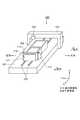
図3には、本発明の第1の実施の形態による三次元造形装置の概略構成説明図が示されている。 FIG. 3 shows a schematic configuration explanatory diagram of the three-dimensional modeling apparatus according to the first embodiment of the present invention.
この図3に示す三次元造形装置10は、造形槽108の右方側面108aにテストパターン用ステージ12が固定されている点において、三次元造形装置100と異なる。 3 is different from the
このテストパターン用ステージ12は、断面L字形状の板状体よりなる取り付け部14と、吐出ヘッド104によりバインダーを吐出してテストパターンを形成するテストパターン形成部16とを備えている。 The
取り付け部14は、そのL字形状を構成する板状体の一方の壁面14aがXY平面と平行となるように、そのL字形状を構成する板状体の他方の壁面14bが造形槽108の右方側面108aにボルトや接着剤などの結合手段により固定されている。 The mounting
そして、テストパターン形成部16は、取り付け部14の壁面14a上に固定されており、テストパターン形成部16の上端部は、造形槽108の上端部108bと一致または概ね一致するように設計されて寸法設定されており、吐出ヘッド104をY軸方向に移動してバインダーを吐出する際に、その移動の妨げとならないように設計されている。 The test
取り付け部14は、テストパターン形成部16の上端部が造形槽108の上端部108bと一致または概ね一致するように、造形槽108にテストパターン形成部16を支持できる構造であればよく、図3に示すようなL字形状を構成する板状体を用いる構造に限定されるものではない。 The
上記したように、三次元造形装置10においては、造形槽108とは別に、造形槽108の領域以外の位置にテストパターンを形成するための専用のテストパターン形成部16が設けられている。 As described above, in the three-
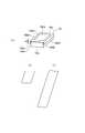
ここで、図4(a)には、テストパターン用ステージ12におけるテストパターン形成部16の詳細な構成をあらわす斜視説明図が示されている。 Here, FIG. 4A is a perspective explanatory view showing a detailed configuration of the test
テストパターン形成部16は、上面16aaが平坦状に形成された台部16aと、台部16aと所定の間隙gを開けて台部16a上に配置される断面コ字形状の板状体よりなるメディアガイド16bとより構成されている。 The test
また、メディアガイド16bは、断面コ字形状に折り曲げられた両方の端部16bbと端部16bcと繋ぐ上部16baに、台部16aの上面16aaの縁部に対応する領域を除く領域を切り欠いて形成した窓部16bdを備えている。 Further, the
なお、メディアガイド16bは、台部16aの上面16aaと上部16baとが所定の間隙gを開けて配置されるように、断面コ字形状に折り曲げられた両方の端部16bbと端部16bcとが、台部16aの両方の側壁部16abと側壁部16acとにそれぞれ固定されている。 The
そして、テストパターン形成部16においては、上記した間隙gから上面16aaと上部16baとの間にテストパターン形成用紙として各種のメディア(媒体)を挿入して配置するものである。 In the test
ここで、上記したテストパターン形成用紙の大きさは、台部16aの上面16aaと一致あるいは概ね一致するものでもよいし(図4(b)を参照する。)、長尺状のものでもよい(図4(c)を参照する。)。 Here, the size of the test pattern forming sheet described above may coincide with or substantially coincide with the upper surface 16aa of the
図4(b)に示す台部16aの上面16aaと一致あるいは概ね一致する大きさのテストパターン形成用紙を用いた場合には、後述するテストパターン形成用紙へのテストパターンの形成毎にテストパターン形成用紙を取り替える処理が必要となるが、図4(c)に示す長尺状のテストパターン形成用紙を用いた場合には、テストパターン形成用紙へのテストパターンの形成毎にテストパターン形成用紙を取り替える必要はなく、テストパターンの形成毎にテストパターンが重ならないようにテストパターン形成用紙をずらしながら使用すればよい。 When a test pattern forming paper having a size that coincides with or substantially coincides with the upper surface 16aa of the
なお、本明細書において「メディア」とは、普通紙などの紙類よりなる各種の記録媒体は勿論のこと、PVC、ポリエステルなどの樹脂材料やアルミ、鉄、木材のような材料などの各種の材料が含まれるものとする。 In this specification, the term “media” refers to various recording media such as plain paper and various recording media such as resin materials such as PVC and polyester, and materials such as aluminum, iron, and wood. Material shall be included.
また、Y軸方向に往復移動可能な吐出ヘッド104は、テストパターン形成部16と対向する上方位置に移動可能な構成とされている。 Further, the
以上の構成において、三次元造形装置10においてテストパターンを形成する際には、テストパターン形成部16における間隙gから上面16aaと上部16baとの間にテストパターン形成用紙を挿入して配置した後に、吐出ヘッド104をテストパターン形成部16の窓部16b上に移動する。 In the above configuration, when the test pattern is formed in the three-
そして、テストパターンの画像データに基づいて、造形槽108をX軸方向に移動するとともに吐出ヘッド104をY軸方向に移動しながら、テストパターン形成部16の窓部16bを介してテストパターン形成用紙に対して吐出ヘッド104からバインダーを吐出すると、吐出されたバインダーは窓部16bを通過してテストパターン形成用紙に付着することになり、これによりテストパターンが形成される。 Then, based on the image data of the test pattern, the test pattern forming sheet is moved through the
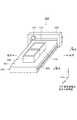
次に、図5には、本発明の第2の実施の形態による三次元造形装置の概略構成説明図が示されている。 Next, FIG. 5 shows a schematic configuration explanatory diagram of the three-dimensional modeling apparatus according to the second embodiment of the present invention.
この図5に示す三次元造形装置20は、貯留槽110の右方側における固定系の基台部101上にテストパターン用ステージ12が固定されている点において、三次元造形装置200と異なる。 The three-
また、三次元造形装置20は、三次元造形装置10では造形槽108の右方側面108aにテストパターン用ステージ12が固定されているのに対して、貯留槽110の右方側における固定系の基台部101上にテストパターン用ステージ12が固定されている点において、三次元造形装置10と異なる。 Further, in the
なお、三次元造形装置20のテストパターン用ステージ12においては、テストパターン形成部16を支持する取り付け部24の構成が上記した取り付け部14の構成と異なっている。 In the
取り付け部24は、テストパターン形成部16の上端部が貯留槽110の上端部110aと一致または概ね一致するように、基台部上にテストパターン形成部16を支持できる構造であればよく、図5に示すような支持棒24aを用いてテストパターン形成部16を支持する構造に限定されるものではない。 The
この三次元造形装置20においても、造形槽108とは別に、造形槽108の領域以外の位置にテストパターンを形成するための専用のテストパターン形成部16が設けられている。 Also in the three-
この三次元造形装置20においてテストパターンを形成する際にも、三次元造形装置10の場合と同様に、テストパターン形成部16における間隙gから上面16aaと上部16baとの間にテストパターン形成用紙を挿入して配置した後に、吐出ヘッド104を窓部16b上に移動する。 When forming a test pattern in the three-
そして、テストパターンの画像データに基づいて、Yレール204をX軸方向に移動するとともに吐出ヘッド104をY軸方向に移動しながら、テストパターン形成部16の窓部16bを介してテストパターン形成用紙に対して吐出ヘッド104からバインダーを吐出すると、吐出されたバインダーは窓部16bを通過してテストパターン形成用紙に付着することになり、これによりテストパターンが形成される。 Then, based on the image data of the test pattern, the test pattern forming sheet is moved through the
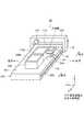
次に、図6には、本発明の第3の実施の形態による三次元造形装置の概略構成説明図が示されている。 Next, FIG. 6 shows a schematic configuration explanatory diagram of the three-dimensional modeling apparatus according to the third embodiment of the present invention.
この図6に示す三次元造形装置30は、造形ステージ前後移動式の三次元造形装置であって、基台部101にX軸方向に延長する溝部32が形成されており、この溝部32内に造形槽108および造形槽108と一体的に連接された収容槽34がX軸方向に移動自在に配置されている。 The three-
造形槽108と収容槽34との位置関係は、造形槽108に対してX軸方向前方側に収容槽34が配置されている。 The positional relationship between the
また、三次元造形装置30は、基台部101上に立ち上がり形成された一対の支持部36により支持されて、XYZ直交座標系におけるY軸方向に沿って延長して配設された貯留槽支持レール38を備えている。 In addition, the three-
この貯留槽支持レールのY軸方向の中央部位には、下方に開閉自在の開口部39aを備えた貯留槽39が配設されている。 A
そして、この三次元造形装置30においても、三次元造形装置10と同様に、造形槽108の右方側面108aにテストパターン用ステージ12が固定されている。 In the
造形槽108の右方側面108aへのテストパターン用ステージ12の取り付け方法は、三次元造形装置10と同様であるため、その詳細な説明は省略する。 Since the method for attaching the
以上の構成において、この三次元造形装置30においては、内部に粉末材料を貯留した貯留槽39の開口部39aと造形槽108とが対向した図6に示す初期状態から、貯留槽39の開口部39aを開いて、造形槽108へ粉末材料を供給する。 In the above-described configuration, in the three-
次に、溝部32内において造形槽108および収容槽34をX軸方向の前方側から後方側に移動することにより、ローラー112が造形槽108上を相対的にX軸方向の後方側から前方側に移動することになり、造形槽108へ供給された粉末材料は造形槽108内に敷き詰められて所定の厚さの粉末層が形成される。 Next, by moving the
なお、この際に、造形槽108の底面は、予め設定された位置まで上昇するように制御される。 At this time, the bottom surface of the
また、造形槽108内において粉末層の形成に用いられなかった余分な粉末材料は、ローラー112が造形槽108から収容槽34へと相対的にX軸方向の後方側から前方側に移動することにより、溝部32内において造形槽108とともにX軸方向の前方側から後方側に移動する収容槽34に収容される。 In addition, excess powder material that has not been used for forming the powder layer in the
上記のようにして造形槽108内に粉末層を形成した後に、溝部32内において造形槽108をX軸方向に移動して、造形槽108を吐出ヘッド104の下方の所定の位置に配置する。 After forming the powder layer in the
それから、三次元造形物の断面形状の画像データに基づいて、溝部32内において造形槽108をX軸方向の前方側から後方側に移動するとともに吐出ヘッド104をY軸方向に移動しながら、造形槽108に形成された粉末層に対して吐出ヘッド104から粉末材料を硬化するバインダーを吐出する。このバインダーの吐出が終了すると、溝部32内に配置された造形槽108をX軸方向の後方側から前方側へ移動して、図6に示す初期状態に復帰させる。 Then, based on the image data of the cross-sectional shape of the three-dimensional structure, the
これにより、粉末層に当該画像データに基づく断面形状を形成し、この処理を繰り返し行って、全ての断面形状を表す画像データに基づく断面形状を順次形成することで、三次元造形物を作製する。 Thereby, a cross-sectional shape based on the image data is formed on the powder layer, this process is repeated, and a cross-sectional shape based on the image data representing all cross-sectional shapes is sequentially formed to produce a three-dimensional structure. .
そして、三次元造形装置30においてテストパターンを形成する際には、テストパターン形成部16における間隙gから上面16aaと上部16baとの間にテストパターン形成用紙を挿入して配置した後に、吐出ヘッド104をテストパターン形成部16の窓部16b上に移動する。 When the test pattern is formed in the three-
そして、テストパターンの画像データに基づいて、溝部32内において造形槽108をX軸方向に移動するとともに吐出ヘッド104をY軸方向に移動しながら、テストパターン形成部16の窓部16bを介してテストパターン形成用紙に対して吐出ヘッド104からバインダーを吐出すると、吐出されたバインダーは窓部16bを通過してテストパターン形成用紙に付着することになり、これによりテストパターンが形成される。 Then, based on the image data of the test pattern, the
次に、図7には、テストパターン形成部へテストパターン形成用紙を供給する方法の変形例の構成を示す断面説明図が示されている。 Next, FIG. 7 is an explanatory cross-sectional view showing the configuration of a modified example of the method for supplying the test pattern forming paper to the test pattern forming unit.
この図7に示すように、ロール状のテストパターン形成用紙を用いて、テストパターン形成部16へテストパターン形成用紙を供給するようにしてもよく、このようにするとテストパターン形成用紙の交換の頻度を著しく低減できるようになる。 As shown in FIG. 7, the test pattern forming paper may be supplied to the test
以上において説明したように、本発明による三次元造形装置10、20、30は、造形槽108以外の領域にテストパターンを形成するための専用のテストパターン形成部16を設けるようにした。 As described above, the three-
これにより、本発明による三次元造形装置10、20、30においては、粉末層上にテストパターンなどを形成する必要がなくなり、テストパターンの形成のために粉末層を形成したり、その粉末層を除去する手間や粉末材料の無駄を省くことができる。 Thereby, in the three-
また、本発明による三次元造形装置10、20、30においては、三次元造形中であっても、造形を一旦休止してテストパターンを形成することができ、吐出ヘッドのノズルの確認や各種の調整が可能になり、非常に使い安く便利である。 Further, in the three-
即ち、本発明による三次元造形装置10、20、30におけるテストパターン形成部は、上記したようなテストパターンを形成する場合に用いることができるのは勿論であるが、吐出ヘッドの傾きや前後調整、ホリゾンタル調整やバイディレクション調整などのサービス時や製造時のメンテナンスパターンなどを形成することができる。 That is, the test pattern forming unit in the three-
本発明は、粉末固着積層方式の三次元造形装置として用いて好適である。 The present invention is suitable for use as a three-dimensional modeling apparatus of a powder-fixed lamination method.
10,20,30,100,200 三次元造形装置、12 テストパターン用ステージ、14,24 取り付け部、16 テストパターン形成部、16a 台部、16b メディアガイド、204 Yレール、104 吐出ヘッド、106,202 Xレール、108 造形槽、110 貯留槽、112 ローラー、g 間隙 10, 20, 30, 100, 200 Three-dimensional modeling apparatus, 12 Test pattern stage, 14, 24 Mounting part, 16 Test pattern forming part, 16a base part, 16b Media guide, 204 Y rail, 104 Discharge head, 106, 202 X rail, 108 modeling tank, 110 storage tank, 112 roller, g gap
Claims (3)
Translated fromJapanese前記造形槽の領域以外の位置にテストパターンを形成するためのテストパターン形成部を設け、
前記吐出ヘッドから前記テストパターン形成部へバインダーを吐出してテストパターンを形成し、
前記造形槽は所定の方向に移動自在に配置されており、
前記テストパターン形成部は前記造形槽と一体的に移動する
ことを特徴とする三次元造形装置。In the three-dimensional modeling apparatus for producing a three-dimensional structure by curing the powder material by discharging the binder from the discharge head to the powder layer made of the powder material formed in the modeling tank,
A test pattern forming unit for forming a test pattern at a position other than the area of the modeling tank is provided,
A test pattern is formedby discharging a binder from the discharge head to the test pattern forming unit,
The modeling tank is movably arranged in a predetermined direction,
The three-dimensional modeling apparatus,wherein the test pattern forming unit moves integrally with the modeling tank .
前記造形槽の領域以外の位置にテストパターンを形成するためのテストパターン形成部を設け、
前記吐出ヘッドから前記テストパターン形成部へバインダーを吐出してテストパターンを形成し、
前記造形槽と前記テストパターン形成部とは固定系部材に配設された
ことを特徴とする三次元造形装置。In the three-dimensional modeling apparatus for producing a three-dimensional structure by curing the powder material by discharging the binder from the discharge head to the powder layer made of the powder material formed in the modeling tank,
A test pattern forming unit for forming a test pattern at a position other than the area of the modeling tank is provided,
A test pattern is formed by discharging a binder from the discharge head to the test pattern forming unit,
The three-dimensional modeling apparatus,wherein the modeling tank and the test pattern forming unit are arranged on a stationary system member .
前記テストパターン形成部は、
上面が平坦状に形成された台部と、
前記台部と所定の間隙を開けて前記台部上に配置される板状体よりなるメディアガイドと
を有して構成され、
前記メディアガイドは前記台部の前記上面の縁部に対応する領域を除く領域を切り欠いて形成した窓部を有し、
前記間隙にテストパターンを形成するメディアを配置した
ことを特徴とする三次元造形装置。In the three-dimensional modeling apparatus of any one of Claim 1 or Claim 2,
The test pattern forming unit includes:
A base portion having a flat upper surface;
A media guide made of a plate-like body disposed on the base part with a predetermined gap from the base part;
Comprising
The media guide has a window portion formed by cutting out a region excluding a region corresponding to the edge portion of the upper surface of the base portion,
A three-dimensional modeling apparatuscomprising a medium for forming a test pattern in the gap .
Priority Applications (1)
| Application Number | Priority Date | Filing Date | Title |
|---|---|---|---|
| JP2015094588AJP6571380B2 (en) | 2015-05-07 | 2015-05-07 | 3D modeling equipment |
Applications Claiming Priority (1)
| Application Number | Priority Date | Filing Date | Title |
|---|---|---|---|
| JP2015094588AJP6571380B2 (en) | 2015-05-07 | 2015-05-07 | 3D modeling equipment |
Publications (2)
| Publication Number | Publication Date |
|---|---|
| JP2016210061A JP2016210061A (en) | 2016-12-15 |
| JP6571380B2true JP6571380B2 (en) | 2019-09-04 |
Family
ID=57549947
Family Applications (1)
| Application Number | Title | Priority Date | Filing Date |
|---|---|---|---|
| JP2015094588AExpired - Fee RelatedJP6571380B2 (en) | 2015-05-07 | 2015-05-07 | 3D modeling equipment |
Country Status (1)
| Country | Link |
|---|---|
| JP (1) | JP6571380B2 (en) |
Families Citing this family (3)
| Publication number | Priority date | Publication date | Assignee | Title |
|---|---|---|---|---|
| KR102125288B1 (en)* | 2018-10-31 | 2020-06-22 | 주식회사 정록 | 3d printer |
| KR101997408B1 (en)* | 2018-10-31 | 2019-07-05 | 이수연 | 3d printer |
| KR102352989B1 (en)* | 2020-08-13 | 2022-01-24 | 한국생산기술연구원 | A powder layer simulator for measuring light absorption and system for measuring light absorption using the same |
Family Cites Families (4)
| Publication number | Priority date | Publication date | Assignee | Title |
|---|---|---|---|---|
| JP2001334582A (en)* | 2000-05-24 | 2001-12-04 | Minolta Co Ltd | Three-dimensional printing apparatus and three-dimensional printing method |
| JP2007503342A (en)* | 2003-05-23 | 2007-02-22 | ズィー コーポレイション | Three-dimensional printing apparatus and method |
| US7824001B2 (en)* | 2004-09-21 | 2010-11-02 | Z Corporation | Apparatus and methods for servicing 3D printers |
| US9126446B1 (en)* | 2014-03-31 | 2015-09-08 | Xerox Corporation | System for detecting inoperative inkjets in printheads ejecting clear ink using a rotating member having a light transmitting surface |
- 2015
- 2015-05-07JPJP2015094588Apatent/JP6571380B2/ennot_activeExpired - Fee Related
Also Published As
| Publication number | Publication date |
|---|---|
| JP2016210061A (en) | 2016-12-15 |
Similar Documents
| Publication | Publication Date | Title |
|---|---|---|
| KR102021416B1 (en) | Construction of a 3d printing device for producing components | |
| KR102039061B1 (en) | Method for manufacturing pieces by the technique of additive manufacturing by pasty process with an improved supply of paste and manufacturing machine for implementing the method | |
| US10124540B2 (en) | Three-dimensional modeled object and support forming method | |
| JP6946319B2 (en) | Manufacturing method and manufacturing equipment | |
| CN106827527B (en) | Method for manufacturing three-dimensional shaped object | |
| JP5700559B2 (en) | Three-dimensional printing method | |
| TWI628069B (en) | Ink jet printing apparatus and ink jet printing method | |
| JP6574603B2 (en) | 3D modeling equipment | |
| US20120133080A1 (en) | Additive Manufacturing Methods for Improved Curl Control and Sidewall Quality | |
| JP6571380B2 (en) | 3D modeling equipment | |
| JP2004358968A (en) | Method and device for manufacturing object according to solid free shape assembly | |
| JP7114444B2 (en) | 3D printer | |
| CN106994782A (en) | Shaped device | |
| JP6624901B2 (en) | 3D modeling equipment | |
| JP6296448B2 (en) | Modeling unit and three-dimensional additive manufacturing apparatus | |
| US12377662B2 (en) | Digital garment printing machine augmented to apply additional materials | |
| CN114789253B (en) | Metal droplet spraying device | |
| KR20020087250A (en) | Three-dimensional printer | |
| TWI616320B (en) | Rapid prototyping apparatus | |
| KR20160034554A (en) | Apparatus and Method for Separation of the three-dimensional sculptures from Bad of 3D print | |
| KR101473911B1 (en) | Method and apparatus for producing image on glass | |
| JP7514199B2 (en) | 3D modeling equipment | |
| JP2018114652A (en) | Three-dimensional object molding apparatus and three-dimensional object molding method | |
| JP7160647B2 (en) | 3D printer | |
| CN118991028A (en) | 3D printer and 3D printing method |
Legal Events
| Date | Code | Title | Description |
|---|---|---|---|
| A621 | Written request for application examination | Free format text:JAPANESE INTERMEDIATE CODE: A621 Effective date:20180425 | |
| A977 | Report on retrieval | Free format text:JAPANESE INTERMEDIATE CODE: A971007 Effective date:20190227 | |
| A131 | Notification of reasons for refusal | Free format text:JAPANESE INTERMEDIATE CODE: A131 Effective date:20190312 | |
| A521 | Request for written amendment filed | Free format text:JAPANESE INTERMEDIATE CODE: A523 Effective date:20190404 | |
| TRDD | Decision of grant or rejection written | ||
| A01 | Written decision to grant a patent or to grant a registration (utility model) | Free format text:JAPANESE INTERMEDIATE CODE: A01 Effective date:20190806 | |
| A61 | First payment of annual fees (during grant procedure) | Free format text:JAPANESE INTERMEDIATE CODE: A61 Effective date:20190808 | |
| R150 | Certificate of patent or registration of utility model | Ref document number:6571380 Country of ref document:JP Free format text:JAPANESE INTERMEDIATE CODE: R150 | |
| LAPS | Cancellation because of no payment of annual fees |