JP6569736B2 - Radiation equipment - Google Patents
Radiation equipmentDownload PDFInfo
- Publication number
- JP6569736B2 JP6569736B2JP2017540424AJP2017540424AJP6569736B2JP 6569736 B2JP6569736 B2JP 6569736B2JP 2017540424 AJP2017540424 AJP 2017540424AJP 2017540424 AJP2017540424 AJP 2017540424AJP 6569736 B2JP6569736 B2JP 6569736B2
- Authority
- JP
- Japan
- Prior art keywords
- light source
- lighting
- radiation
- unit
- led
- Prior art date
- Legal status (The legal status is an assumption and is not a legal conclusion. Google has not performed a legal analysis and makes no representation as to the accuracy of the status listed.)
- Active
Links
Images


Classifications
- A—HUMAN NECESSITIES
- A61—MEDICAL OR VETERINARY SCIENCE; HYGIENE
- A61B—DIAGNOSIS; SURGERY; IDENTIFICATION
- A61B6/00—Apparatus or devices for radiation diagnosis; Apparatus or devices for radiation diagnosis combined with radiation therapy equipment
- A61B6/08—Auxiliary means for directing the radiation beam to a particular spot, e.g. using light beams
- A—HUMAN NECESSITIES
- A61—MEDICAL OR VETERINARY SCIENCE; HYGIENE
- A61B—DIAGNOSIS; SURGERY; IDENTIFICATION
- A61B6/00—Apparatus or devices for radiation diagnosis; Apparatus or devices for radiation diagnosis combined with radiation therapy equipment
- A61B6/06—Diaphragms
- A—HUMAN NECESSITIES
- A61—MEDICAL OR VETERINARY SCIENCE; HYGIENE
- A61B—DIAGNOSIS; SURGERY; IDENTIFICATION
- A61B6/00—Apparatus or devices for radiation diagnosis; Apparatus or devices for radiation diagnosis combined with radiation therapy equipment
- A61B6/44—Constructional features of apparatus for radiation diagnosis
- A61B6/4494—Means for identifying the diagnostic device
- A—HUMAN NECESSITIES
- A61—MEDICAL OR VETERINARY SCIENCE; HYGIENE
- A61B—DIAGNOSIS; SURGERY; IDENTIFICATION
- A61B6/00—Apparatus or devices for radiation diagnosis; Apparatus or devices for radiation diagnosis combined with radiation therapy equipment
- A61B6/54—Control of apparatus or devices for radiation diagnosis
- G—PHYSICS
- G21—NUCLEAR PHYSICS; NUCLEAR ENGINEERING
- G21K—TECHNIQUES FOR HANDLING PARTICLES OR IONISING RADIATION NOT OTHERWISE PROVIDED FOR; IRRADIATION DEVICES; GAMMA RAY OR X-RAY MICROSCOPES
- G21K1/00—Arrangements for handling particles or ionising radiation, e.g. focusing or moderating
- G21K1/02—Arrangements for handling particles or ionising radiation, e.g. focusing or moderating using diaphragms, collimators
Landscapes
- Health & Medical Sciences (AREA)
- Life Sciences & Earth Sciences (AREA)
- Engineering & Computer Science (AREA)
- Medical Informatics (AREA)
- Physics & Mathematics (AREA)
- High Energy & Nuclear Physics (AREA)
- Radiology & Medical Imaging (AREA)
- Molecular Biology (AREA)
- Optics & Photonics (AREA)
- Pathology (AREA)
- Biophysics (AREA)
- Biomedical Technology (AREA)
- Heart & Thoracic Surgery (AREA)
- Nuclear Medicine, Radiotherapy & Molecular Imaging (AREA)
- Surgery (AREA)
- Animal Behavior & Ethology (AREA)
- General Health & Medical Sciences (AREA)
- Public Health (AREA)
- Veterinary Medicine (AREA)
- Spectroscopy & Molecular Physics (AREA)
- General Engineering & Computer Science (AREA)
- Apparatus For Radiation Diagnosis (AREA)
Description
Translated fromJapaneseこの発明は、被検体に向けて放射線を照射する放射線照射手段を備えた放射線装置に係り、特に、放射線の照射野を制御する技術に関する。 The present invention relates to a radiation apparatus provided with radiation irradiating means for irradiating a subject with radiation, and more particularly to a technique for controlling a radiation irradiation field.
放射線としてX線を例に採って説明するとともに、放射線装置としてX線撮影を行うX線撮影装置を例に採って説明する。X線撮影装置は、被検体に向けてX線を照射するX線管(放射線照射手段)を備えるとともに、X線管からのX線照射領域をリーフにより制御するコリメータ(X線絞り)と、コリメータを介して被検体を透過したX線を検出するX線検出器(X線フィルム,CR(Computed Radiography)またはFPD(Flat Panel Detector))とを備えている。 An explanation will be given by taking an X-ray as an example of radiation, and an X-ray imaging apparatus that performs X-ray imaging as an example of the radiation apparatus will be described. An X-ray imaging apparatus includes an X-ray tube (radiation irradiation means) that irradiates an X-ray toward a subject, and a collimator (X-ray diaphragm) that controls an X-ray irradiation region from the X-ray tube with a leaf; An X-ray detector (X-ray film, CR (Computed Radiography) or FPD (Flat Panel Detector)) that detects X-rays transmitted through the subject via a collimator is provided.
X線管からのX線照射領域をリーフにより制御するコリメータにおいては、コリメータにより形成される矩形のX線の照射野は、例えばコリメータのパネル面に設けられた縦寸法調整つまみおよび横寸法調整つまみにより、その2辺の長さを調整することができる。しかしながら、この調整をX線撮影前に被検体にX線を照射しながらモニタリングして行うことは被検体の被曝の増加につながる。 In a collimator that controls an X-ray irradiation area from an X-ray tube with a leaf, a rectangular X-ray irradiation field formed by the collimator is, for example, a vertical dimension adjustment knob and a horizontal dimension adjustment knob provided on the panel surface of the collimator. Thus, the length of the two sides can be adjusted. However, performing this adjustment while monitoring the subject while irradiating the subject with X-rays before X-ray imaging leads to an increase in subject exposure.
そこで、このような被曝を防止するために、通常は、コリメータは光源となる照射野ランプ(コリメータランプ)を内蔵し、X線の代わりに可視光(以下、「光」と略記する)を照射する機能を有している。X線の照射野と一致するように調整された光の照射野を確認することで、X線を照射することなく撮影前に照射野の位置および寸法の調整を行うことができる。また、光を照射するためのコリメータランプの点灯は点灯ボタンによって行われ、例えば点灯ボタンの1回押下で所定時間(例えば30秒)が経過するとコリメータランプが自動的に消灯するように構成されている。 Therefore, in order to prevent such exposure, the collimator normally incorporates an irradiation field lamp (collimator lamp) serving as a light source, and emits visible light (hereinafter abbreviated as “light”) instead of X-rays. It has a function to do. By confirming the light irradiation field adjusted to coincide with the X-ray irradiation field, the position and size of the irradiation field can be adjusted before imaging without irradiating X-rays. Further, the collimator lamp for irradiating light is turned on by a lighting button. For example, the collimator lamp is automatically turned off when a predetermined time (for example, 30 seconds) elapses when the lighting button is pressed once. Yes.
所定時間を超えてコリメータランプを連続して点灯させるには、点灯ボタンを複数回押下することで行う。具体的には、上述した所定時間が経過してコリメータランプが消灯した直後に点灯ボタンを再度に押下することを繰り返すことで、所定時間を超えてもコリメータランプを連続して点灯させることができる。 To continuously turn on the collimator lamp beyond the predetermined time, the lighting button is pressed a plurality of times. Specifically, the collimator lamp can be continuously lit even if the predetermined time is exceeded by repeating the pressing of the lighting button again immediately after the above-mentioned predetermined time has passed and the collimator lamp is extinguished. .
コリメータランプは、発熱の大きいハロゲンランプを使用しており、所定時間を超えてコリメータランプを長時間点灯させると、ハロゲンランプからの発熱により装置外装の温度が上昇して過熱する恐れがある。そこで、設定温度を超えないようにコリメータランプの点灯時間を制限することで温度制限を行うX線撮影装置が本出願人から提案されている(例えば、特許文献1参照)。 As the collimator lamp, a halogen lamp that generates a large amount of heat is used. If the collimator lamp is turned on for a long period of time exceeding a predetermined time, the temperature of the exterior of the apparatus may increase due to the heat generated from the halogen lamp, causing overheating. Therefore, an X-ray imaging apparatus that limits temperature by limiting the lighting time of the collimator lamp so as not to exceed the set temperature has been proposed by the present applicant (see, for example, Patent Document 1).
具体的には、特許文献1:特開2012−55421号公報の図3に示すように、制御部は、照射野ランプ(コリメータランプ)の点灯時間と温度上昇との関係、およびコリメータランプの消灯時間と温度降下との関係を示す温度昇降データを記憶する記憶部と、コリメータランプの点灯時間および消灯時間と記憶部された温度昇降データとから、現在のコリメータランプの温度を演算する疑似温度カウンターと、疑似温度カウンターにより演算されたコリメータランプの温度が設定温度を超えたときにコリメータランプの点灯を禁止するとともに、疑似温度カウンターにより演算されたコリメータランプの温度が設定温度以下となったときにコリメータランプの点灯を許可する点灯制御部とを備えている。 Specifically, as shown in FIG. 3 of Japanese Patent Application Laid-Open No. 2012-55421, the control unit controls the relationship between the lighting time of the irradiation field lamp (collimator lamp) and the temperature rise, and turns off the collimator lamp. A pseudo temperature counter that calculates the current temperature of the collimator lamp from the storage unit that stores temperature rise / fall data indicating the relationship between time and temperature drop, and the temperature rise / fall time of the collimator lamp and the stored temperature rise / fall data When the temperature of the collimator lamp calculated by the pseudo temperature counter exceeds the set temperature, the lighting of the collimator lamp is prohibited, and when the temperature of the collimator lamp calculated by the pseudo temperature counter falls below the set temperature And a lighting control unit that permits lighting of the collimator lamp.
上述した構成により、装置の製造コストを上昇させることなく、装置の温度が一定以上となることを防止することができる。また、装置の温度が一定以下となったときにはX線撮影を再開することが可能となる。 With the above-described configuration, it is possible to prevent the temperature of the apparatus from exceeding a certain level without increasing the manufacturing cost of the apparatus. Further, X-ray imaging can be resumed when the temperature of the apparatus falls below a certain level.
また、技師などの使用者が必要とする作業時間に応じて、設定された点灯時間を変更して制御するX線撮影装置がある(例えば、特許文献2参照)。その他に、バッテリーを搭載した移動式X線撮影装置において、コリメータランプの消費電力およびバッテリーの残存電力に応じて、点灯時間を制御するX線撮影装置がある(例えば、特許文献3参照)。 In addition, there is an X-ray imaging apparatus that changes and controls a set lighting time according to a work time required by a user such as an engineer (see, for example, Patent Document 2). In addition, there is an X-ray imaging apparatus that controls the lighting time according to the power consumption of the collimator lamp and the remaining power of the battery in a mobile X-ray imaging apparatus equipped with a battery (see, for example, Patent Document 3).
しかしながら、従来技術の場合には、装置を連続して使用したい場合でも温度制限でコリメータランプの点灯が禁止された際には、装置を使用することができず、さらに照射野を調整することができないという問題点がある。その結果、技師などの使用者が装置を使用したいタイミングで装置を使用することができず、患者である被検体を待たせてしまうという不便性の問題が生じた。 However, in the case of the prior art, even if it is desired to use the device continuously, the device cannot be used when the collimator lamp is turned off due to temperature limitation, and the irradiation field can be further adjusted. There is a problem that it is not possible. As a result, a user such as an engineer cannot use the device at the timing at which he / she wants to use the device, causing a problem of inconvenience that the patient as a patient is kept waiting.
従来のコリメータランプは、上述したように発熱の大きい(100W程度の消費電力がある)ハロゲンランプを使用しているので、上述した特許文献1:特開2012−55421号公報のように、装置外装の温度を考慮した温度制限などのような保護(プロテクト)が必要であった。そこで、発光ダイオード(LED: Light Emitting Diode)などの消費電力の小さい光源を使用することで、10W〜20W程度の消費電力でハロゲンランプと同等の照度が得られる。よって、発光ダイオード(LED)を連続して点灯させても装置外装の温度が高温にはならないので、外装温度に考慮する必要がなくなる。 Since the conventional collimator lamp uses a halogen lamp that generates a large amount of heat (has a power consumption of about 100 W) as described above, as in the above-mentioned Patent Document 1: Japanese Patent Application Laid-Open No. 2012-55421, the exterior of the apparatus is used. It was necessary to provide protection such as temperature limitation in consideration of the temperature. Therefore, by using a light source with low power consumption such as a light emitting diode (LED), illuminance equivalent to that of a halogen lamp can be obtained with power consumption of about 10 W to 20 W. Therefore, even if the light emitting diode (LED) is continuously turned on, the temperature of the exterior of the apparatus does not become high, so it is not necessary to consider the exterior temperature.
このように、近年、LEDからなるコリメータランプを有するX線撮影装置が使用されている。一方、LEDのみからなるコリメータランプを有するX線撮影装置を使用しようとすると、装置全体を準備する必要がある。さらに、LEDの場合には直流により点灯するので、交流電源を直接に取り込むことができず、交流を直流に変換するAC/DC変換基板を準備する必要がある。そこで、汎用性を高めるためにハロゲンランプおよびLEDの両方を点灯制御可能な構成を備えていずれか一方に切り替えるように構成された機器が開発されている。 Thus, in recent years, an X-ray imaging apparatus having a collimator lamp made of LEDs has been used. On the other hand, if an X-ray imaging apparatus having a collimator lamp composed only of LEDs is to be used, the entire apparatus needs to be prepared. Furthermore, since the LED is lit by direct current, an alternating current power source cannot be directly taken in, and it is necessary to prepare an AC / DC conversion board for converting alternating current to direct current. Therefore, in order to improve versatility, a device has been developed that has a configuration in which both of the halogen lamp and the LED can be controlled to be switched to one of them.
このような機器を使用する場合には、AC/DC変換基板の他に、ハロゲンランプおよびLEDの両方に接続可能で、いずれか一方に切り替え可能な制御基板、あるいはハロゲンランプを点灯させるためのハロゲンランプ用制御基板(ハロゲンランプ点灯用回路)およびLEDを点灯させるためのLED用制御基板(LED点灯用回路)のみを準備するだけで済み、AC/DC変換基板や制御基板以外のX線撮影装置内の機器は既存のものを利用することができる。なお、AC/DC変換基板や制御基板は装置本体に搭載されている。 When using such a device, in addition to the AC / DC conversion board, it can be connected to both a halogen lamp and an LED, and can be switched to either one, or a halogen for lighting the halogen lamp. It is only necessary to prepare a lamp control board (halogen lamp lighting circuit) and an LED control board (LED lighting circuit) for lighting the LED, and an X-ray imaging apparatus other than the AC / DC conversion board and the control board. Existing equipment can be used. The AC / DC conversion board and the control board are mounted on the apparatus main body.
このように、装置本体に接続された光源をハロゲンランプからLEDに切り替えて変更した場合には、LEDが接続されていることを、中央演算処理装置(CPU)などで構成された点灯制御部が検知することで、点灯制御部は温度制限を無視することができる。しかし、LEDが接続されていることを点灯制御部に知らせるための設定が必要である。 As described above, when the light source connected to the apparatus main body is changed from the halogen lamp to the LED, the lighting control unit configured by a central processing unit (CPU) or the like indicates that the LED is connected. By detecting, the lighting control unit can ignore the temperature limit. However, a setting for notifying the lighting control unit that the LED is connected is necessary.
通常、これらのAC/DC変換基板や制御基板を装置本体に搭載して、装置を組み立てた後に出荷する。あるいは保守時に、これらのAC/DC変換基板や制御基板を装置本体に搭載する。よって、出荷時の組み立て者や保守時のサービスマンが、LEDが接続されていることを点灯制御部に知らせるための設定を手動で行う。出荷時の組み立て者や保守時のサービスマンなどの人間が手動で設定する場合、設定の手間がかかるとともに、誤設定のリスクがある。 Usually, these AC / DC conversion boards and control boards are mounted on the apparatus main body and the apparatus is assembled before shipment. Alternatively, these AC / DC conversion boards and control boards are mounted on the apparatus main body during maintenance. Therefore, an assembly person at the time of shipment or a service person at the time of maintenance manually performs setting for notifying the lighting control unit that the LED is connected. When manually set by a person such as an assembler at the time of shipment or a service person at the time of maintenance, it takes time for setting and there is a risk of erroneous setting.
特に、誤設定のリスクについて具体的に述べる。実際にはLEDが接続されているのにも関わらずハロゲンランプの設定をしてしまった場合には、従来の通りに温度制限がかかってしまい、長時間に連続して使用することができないというだけで済む。しかし、逆に、実際にはハロゲンランプが接続されているのにも関わらずLEDの設定をしてしまった場合には、外装温度の過熱に対する制限が解除されてしまうので、装置外装が過熱することが起こり得てしまう。 In particular, the risk of misconfiguration will be described specifically. In fact, when the halogen lamp is set despite the fact that the LED is connected, the temperature is limited as before, and it cannot be used continuously for a long time. Just do it. However, conversely, if the LED is set despite the fact that a halogen lamp is connected, the limitation on the overheating of the exterior temperature is lifted, so the exterior of the apparatus overheats. Can happen.
この発明は、このような事情に鑑みてなされたものであって、誤設定のリスクを防止し、光源の切り替え設定を自動的に行うことができる放射線装置を提供することを目的とする。 The present invention has been made in view of such circumstances, and an object of the present invention is to provide a radiation apparatus that can prevent the risk of erroneous setting and can automatically perform switching setting of a light source.
この発明は、このような目的を達成するために、次のような構成をとる。
すなわち、この発明に係る放射線装置(「第1の発明」と呼ぶ)は、被検体に向けて放射線を照射する放射線照射手段を備えた放射線装置であって、放射線の照射野に可視光を照射する光源と、当該光源の点灯を制御する光源点灯制御手段と、前記放射線装置の外装の温度が所定の温度以下になるように前記光源の点灯時間を制限する点灯時間制限手段と、装置本体に接続された前記光源の種類を判別する光源種類判別手段とを備え、前記光源種類判別手段による判別の結果に基づいて、前記点灯時間制限手段が制限する点灯時間を前記光源点灯制御手段が変更することを特徴とするものである。In order to achieve such an object, the present invention has the following configuration.
That is, a radiation apparatus according to the present invention (referred to as “first invention”) is a radiation apparatus that includes radiation irradiating means for irradiating a subject with radiation, and irradiates the radiation field with visible light. A light source, a light source lighting control unit that controls lighting of the light source, a lighting time limiting unit that limits a lighting time of the light source so thata temperature of an exterior of the radiation device is equal to or lower than a predetermined temperature, and a device body A light source type discriminating unit for discriminating the type of the connected light source, and the light source lighting control unit changes a lighting time limited by the lighting time limiting unit based on a result of discrimination by the light source type discriminating unit. It is characterized by this.
この発明に係る放射線装置(第1の発明)によれば、放射線の照射野に可視光を照射する光源や、当該光源の点灯を制御する光源点灯制御手段の他に、所定の温度以下になるように光源の点灯時間を制限する点灯時間制限手段と、装置本体に接続された光源の種類を判別する光源種類判別手段とを備えている。点灯時間制限手段が所定の温度以下になるように光源の点灯時間を制限することにより、装置外装の温度が過熱しないようにする。光源種類判別手段での装置本体に接続された光源の種類を判別することによる判別の結果に基づいて、点灯時間制限手段が制限する点灯時間を光源点灯制御手段が変更することより、出荷時の組み立て者や保守時のサービスマンなどの人間が手動で設定する必要がなく、光源の切り替え設定を自動的に行うことができる。また、光源種類判別手段による判別の結果に基づいて点灯時間制限手段が制限する点灯時間を変更するので、誤設定のリスクを防止することができる。例えば、発熱の大きい種類の光源(例えばハロゲンランプ)が実際に接続されていても、当該光源の種類を接続対象として自動的に判別することで、点灯時間を短く制限して過熱を防止する。逆に、発熱の小さい種類の光源(例えばLED)が実際に接続されていても、当該光源の種類を接続対象として自動的に判別することで、点灯時間を長く設定して長時間に連続して使用する。よって、発熱の大きい種類の光源を用いて外装温度の過熱の可能性がある場合には過熱を防止し、発熱の小さい種類の光源を用いて外装温度の過熱の可能性がない場合には長時間に連続して使用することが可能となる。その結果、誤設定のリスクを防止し、光源の切り替え設定を自動的に行うことができる。 According to the radiation apparatus according to the present invention (the first invention), in addition to the light source that irradiates the radiation field with visible light and the light source lighting control means that controls the lighting of the light source, the temperature falls below a predetermined temperature. In this way, there are provided lighting time limiting means for limiting the lighting time of the light source and light source type determination means for determining the type of the light source connected to the apparatus main body. By limiting the lighting time of the light source so that the lighting time limiting means is below a predetermined temperature, the temperature of the exterior of the apparatus is prevented from overheating. Based on the result of the determination by determining the type of the light source connected to the apparatus main body in the light source type determination means, the light source lighting control means changes the lighting time limited by the lighting time limiting means, so that It is not necessary for a person such as an assembler or a maintenance service person to manually set the light source, and the light source switching setting can be automatically performed. In addition, since the lighting time limited by the lighting time limiting unit is changed based on the determination result by the light source type determining unit, the risk of erroneous setting can be prevented. For example, even when a light source of a large amount of heat (for example, a halogen lamp) is actually connected, by automatically determining the type of the light source as a connection target, the lighting time is limited to prevent overheating. On the other hand, even if a light source (for example, LED) that generates a small amount of heat is actually connected, the lighting time is set to a long time by automatically determining the type of the light source as the connection target, and continues for a long time. To use. Therefore, it is possible to prevent overheating when there is a possibility of overheating of the exterior temperature using a type of light source that generates a large amount of heat, and long when there is no possibility of overheating of the exterior temperature using a type of light source that generates less heat. It can be used continuously in time. As a result, the risk of erroneous setting can be prevented, and the light source switching setting can be performed automatically.
また、第1の発明とは別の発明に係る放射線装置(「第2の発明」と呼ぶ)は、被検体に向けて放射線を照射する放射線照射手段を備えた放射線装置であって、放射線の照射野に可視光を照射する光源と、当該光源の点灯を制御する光源点灯制御手段と、前記放射線装置の外装の温度が所定の温度以下になるように前記光源の点灯時間を制限する点灯時間制限手段と、装置本体に接続された前記光源の種類を判別する光源種類判別手段とを備え、前記光源種類判別手段による判別の結果により前記光源が半導体光源である場合に、前記点灯時間制限手段を前記光源点灯制御手段が無効にすることを特徴とするものである。A radiation device according to an invention different from the first invention (referred to as “second invention”) is a radiation device comprising radiation irradiating means for irradiating a subject with radiation, A light source that irradiates the irradiation field with visible light, a light source lighting control unit that controls lighting of the light source, and a lighting time that limits the lighting time of the light source so thatthe temperature of the exterior of the radiation device is equal to or lower than a predetermined temperature. And a light source type discriminating unit for discriminating the type of the light source connected to the apparatus main body, and the lighting time limiting unit when the light source is a semiconductor light source as a result of discrimination by the light source type discriminating unit. Is disabled by the light source lighting control means.
この発明に係る放射線装置(第2の発明)によれば、第1の発明と同様に、放射線の照射野に可視光を照射する光源や、当該光源の点灯を制御する光源点灯制御手段の他に、所定の温度以下になるように光源の点灯時間を制限する点灯時間制限手段と、装置本体に接続された光源の種類を判別する光源種類判別手段とを備えている。点灯時間制限手段が所定の温度以下になるように光源の点灯時間を制限することにより、装置外装の温度が過熱しないようにする。第1の発明と相違して、光源種類判別手段での装置本体に接続された光源の種類を判別することによる判別の結果により光源が半導体光源である場合に、点灯時間制限手段を光源点灯制御手段が無効にする。半導体光源は、位相のそろった可視光を放射するレーザダイオード(LD: Laser Diode)や、上述したようなLEDなどのように発熱の小さい半導体光源で構成されている。したがって、発熱の小さい半導体光源が実際に接続されている場合には点灯時間制限手段を無効にすることにより、点灯時間を長く設定して長時間に連続して使用する。逆に、半導体光源以外の発熱の大きい種類の光源(例えばハロゲンランプ)が実際に接続されている場合には点灯時間制限手段を有効にすることにより、点灯時間を短く制限して過熱を防止する。よって、発熱の小さい半導体光源を用いて外装温度の過熱の可能性がない場合には点灯時間制限手段を無効にすることにより、長時間に連続して使用することが可能となる。その結果、誤設定のリスクを防止し、光源の切り替え設定を自動的に行うことができる。 According to the radiation apparatus according to the present invention (second invention), as in the first invention, in addition to the light source that irradiates the radiation field with visible light and the light source lighting control means that controls the lighting of the light source. In addition, there are provided lighting time limiting means for limiting the lighting time of the light source so as to be below a predetermined temperature, and light source type determining means for determining the type of the light source connected to the apparatus main body. By limiting the lighting time of the light source so that the lighting time limiting means is below a predetermined temperature, the temperature of the exterior of the apparatus is prevented from overheating. Unlike the first invention, when the light source is a semiconductor light source according to the result of determination by determining the type of the light source connected to the apparatus main body by the light source type determination means, the lighting time limit means is controlled to turn on the light source. Means invalidate. The semiconductor light source is composed of a semiconductor light source that generates a small amount of heat, such as a laser diode (LD) that emits visible light in phase and an LED as described above. Therefore, when a semiconductor light source with small heat generation is actually connected, the lighting time limit means is disabled, so that the lighting time is set long and used continuously for a long time. Conversely, when a light source of a large heat generation other than a semiconductor light source (for example, a halogen lamp) is actually connected, the lighting time limiting means is enabled to limit the lighting time to prevent overheating. . Therefore, when there is no possibility of overheating of the exterior temperature using a semiconductor light source that generates a small amount of heat, the lighting time limiting means is disabled to enable continuous use for a long time. As a result, the risk of erroneous setting can be prevented, and the light source switching setting can be performed automatically.
また、第1の発明・第2の発明とは別の発明に係る放射線装置(「第3の発明」と呼ぶ)は、被検体に向けて放射線を照射する放射線照射手段を備えた放射線装置であって、放射線の照射野に可視光を照射する光源と、当該光源の点灯を制御する光源点灯制御手段と、前記放射線装置の外装の温度が所定の温度以下になるように前記光源の点灯電力を制限する点灯電力制限手段と、装置本体に接続された前記光源の種類を判別する光源種類判別手段とを備え、前記光源種類判別手段による判別の結果に基づいて、前記点灯電力制限手段が制限する点灯電力を前記光源点灯制御手段が変更することを特徴とするものである。A radiation apparatus according to an invention different from the first invention and the second invention (referred to as “third invention”) is a radiation apparatus provided with radiation irradiation means for irradiating a subject with radiation. A light source that emits visible light to a radiation field, a light source lighting control unit that controls lighting of the light source, and a lighting power of the light source so thata temperature of an exterior of the radiation device is equal to or lower than a predetermined temperature. Lighting power limiting means for limiting the light source, and light source type determining means for determining the type of the light source connected to the apparatus main body, and the lighting power limiting means is limited based on the result of determination by the light source type determining means The lighting power to be changed is changed by the light source lighting control means.
この発明に係る放射線装置(第3の発明)によれば、放射線の照射野に可視光を照射する光源や、当該光源の点灯を制御する光源点灯制御手段の他に、所定の温度以下になるように光源の点灯電力を制限する点灯電力制限手段と、装置本体に接続された光源の種類を判別する光源種類判別手段とを備えている。点灯電力制限手段が所定の温度以下になるように光源の点灯電力を制限することにより、装置外装の温度が過熱しないようにする。光源種類判別手段での装置本体に接続された光源の種類を判別することによる判別の結果に基づいて、点灯電力制限手段が制限する点灯電力を光源点灯制御手段が変更することより、出荷時の組み立て者や保守時のサービスマンなどの人間が手動で設定する必要がなく、光源の切り替え設定を自動的に行うことができる。また、光源種類判別手段による判別の結果に基づいて点灯電力制限手段が制限する点灯電力を変更するので、誤設定のリスクを防止することができる。例えば、発熱の大きい種類の光源(例えばハロゲンランプ)が実際に接続されていても、当該光源の種類を接続対象として自動的に判別することで、例えばタイマーで点灯時間を監視した後に、点灯電力を下げて制限して過熱を防止する。逆に、発熱の小さい種類の光源(例えばLED)が実際に接続されていても、当該光源の種類を接続対象として自動的に判別することで、例えばタイマーで点灯時間を監視した後でも、点灯電力の下げ率を抑えて設定する。よって、発熱の大きい種類の光源を用いて外装温度の過熱の可能性がある場合には過熱を防止し、発熱の小さい種類の光源を用いて外装温度の過熱の可能性がない場合には点灯電力の下げ率を抑えて設定することが可能となる。その結果、誤設定のリスクを防止し、光源の切り替え設定を自動的に行うことができる。 According to the radiation apparatus according to the present invention (third invention), in addition to the light source that irradiates the radiation field with visible light and the light source lighting control means that controls the lighting of the light source, the temperature is below a predetermined temperature. As described above, a lighting power limiting means for limiting the lighting power of the light source and a light source type determining means for determining the type of the light source connected to the apparatus main body are provided. By limiting the lighting power of the light source so that the lighting power limiting means is below a predetermined temperature, the temperature of the apparatus exterior is prevented from overheating. Based on the result of the determination by determining the type of the light source connected to the apparatus main body in the light source type determining means, the light source lighting control means changes the lighting power limited by the lighting power limiting means. It is not necessary for a person such as an assembler or a maintenance service person to manually set the light source, and the light source switching setting can be automatically performed. Further, since the lighting power limited by the lighting power limiting means is changed based on the determination result by the light source type determining means, the risk of erroneous setting can be prevented. For example, even if a light source of a large amount of heat (for example, a halogen lamp) is actually connected, the lighting power is automatically determined after the lighting time is monitored by, for example, a timer by automatically determining the type of the light source as a connection target. Lower to limit to prevent overheating. On the other hand, even if a light source of a low heat generation type (for example, LED) is actually connected, it can be turned on even after monitoring the lighting time with a timer, for example, by automatically determining the type of the light source as the connection target. Set with a lower power reduction rate. Therefore, use a light source with large heat generation to prevent overheating of the exterior temperature, and use a light source with low heat generation to turn on when there is no possibility of overheating of the exterior temperature. It is possible to set the power reduction rate while suppressing it. As a result, the risk of erroneous setting can be prevented, and the light source switching setting can be performed automatically.
また、第1の発明〜第3の発明とは別の発明に係る放射線装置(「第4の発明」と呼ぶ)は、被検体に向けて放射線を照射する放射線照射手段を備えた放射線装置であって、放射線の照射野に可視光を照射する光源と、当該光源の点灯を制御する光源点灯制御手段と、前記放射線装置の外装の温度が所定の温度以下になるように前記光源の点灯電力を制限する点灯電力制限手段と、装置本体に接続された前記光源の種類を判別する光源種類判別手段とを備え、前記光源種類判別手段による判別の結果により前記光源が半導体光源である場合に、前記点灯電力制限手段を前記光源点灯制御手段が無効にすることを特徴とするものである。A radiation apparatus according to an invention different from the first to third inventions (referred to as a “fourth invention”) is a radiation apparatus provided with radiation irradiating means for irradiating a subject with radiation. A light source that emits visible light to a radiation field, a light source lighting control unit that controls lighting of the light source, and a lighting power of the light source so thata temperature of an exterior of the radiation device is equal to or lower than a predetermined temperature. Lighting power limiting means for limiting the light source, and light source type determining means for determining the type of the light source connected to the apparatus main body, and when the light source is a semiconductor light source according to the result of determination by the light source type determining means, The lighting power limiting means is invalidated by the light source lighting control means.
この発明に係る放射線装置(第4の発明)によれば、第3の発明と同様に、放射線の照射野に可視光を照射する光源や、当該光源の点灯を制御する光源点灯制御手段の他に、所定の温度以下になるように光源の点灯電力を制限する点灯電力制限手段と、装置本体に接続された光源の種類を判別する光源種類判別手段とを備えている。点灯電力制限手段が所定の温度以下になるように光源の点灯電力を制限することにより、装置外装の温度が過熱しないようにする。第3の発明と相違して、光源種類判別手段での装置本体に接続された光源の種類を判別することによる判別の結果により光源が半導体光源である場合に、点灯電力制限手段を光源点灯制御手段が無効にする。半導体光源は、第2の発明でも述べたように、レーザダイオード(LD)や、上述したようなLEDなどのように発熱の小さい半導体光源で構成されている。したがって、発熱の小さい半導体光源が実際に接続されている場合には点灯電力制限手段を無効にすることにより、点灯電力を下げずに設定、あるいは大きく設定する。逆に、半導体光源以外の発熱の大きい種類の光源(例えばハロゲンランプ)が実際に接続されている場合には点灯電力制限手段を有効にすることにより、点灯電力を下げて制限して過熱を防止する。よって、発熱の小さい半導体光源を用いて外装温度の過熱の可能性がない場合には点灯電力制限手段を無効にすることにより、点灯電力を下げずに設定、あるいは大きく設定することが可能となる。その結果、誤設定のリスクを防止し、光源の切り替え設定を自動的に行うことができる。 According to the radiation apparatus according to the present invention (fourth invention), as in the third invention, in addition to the light source that irradiates the radiation field with visible light and the light source lighting control means that controls the lighting of the light source. In addition, there are provided lighting power limiting means for limiting the lighting power of the light source so as to be lower than a predetermined temperature, and light source type determining means for determining the type of the light source connected to the apparatus main body. By limiting the lighting power of the light source so that the lighting power limiting means is below a predetermined temperature, the temperature of the apparatus exterior is prevented from overheating. Unlike the third invention, when the light source is a semiconductor light source as a result of determination by determining the type of the light source connected to the apparatus main body by the light source type determination means, the lighting power limiting means is controlled to turn on the light source. Means invalidate. As described in the second aspect of the invention, the semiconductor light source is composed of a semiconductor light source that generates little heat, such as a laser diode (LD) or an LED as described above. Therefore, when a semiconductor light source with low heat generation is actually connected, the lighting power limiting means is disabled, so that the lighting power is set or set large without lowering. Conversely, if a light source of a large heat generation other than a semiconductor light source (for example, a halogen lamp) is actually connected, the lighting power limiting means is enabled to reduce the lighting power and prevent overheating. To do. Therefore, when there is no possibility of overheating of the exterior temperature using a semiconductor light source that generates a small amount of heat, it is possible to set the lighting power without setting it down or to set it large by disabling the lighting power limiting means. . As a result, the risk of erroneous setting can be prevented, and the light source switching setting can be performed automatically.
上述したこれらの発明に係る放射線装置(第1の発明〜第4の発明)における光源の種類の判別の一例は、下記の通りである。
すなわち、光源種類判別手段は、光源が接続されたことを検出する。この一例の場合には、例えば制御基板を1つ用意して、装置本体に搭載された当該制御基板に光源を接続するだけで、光源の種類の判別を実現することができる。An example of the determination of the type of light source in the above-described radiation apparatus (first to fourth inventions) according to these inventions is as follows.
That is, the light source type discriminating unit detects that the light source is connected. In the case of this example, for example, by preparing one control board and connecting the light source to the control board mounted on the apparatus main body, the type of the light source can be determined.
上述したこれらの発明に係る放射線装置(第1の発明〜第4の発明)における光源の種類の判別の他の一例は、下記の通りである。
すなわち、光源種類判別手段は、光源点灯制御手段が光源を点灯させるための当該光源専用の制御基板に搭載されたことを検出する。この一例の場合には、例えば光源の種類の数だけ光源専用の制御基板(光源専用の点灯用回路)を用意して、いずれか1つの制御基板を装置本体に搭載して、それぞれに同じ光源点灯制御手段(例えばCPU)を搭載するだけで、光源の種類の判別を実現することができる。Another example of the determination of the type of light source in the above-described radiation apparatus (the first to fourth inventions) is as follows.
In other words, the light source type determining means detects that the light source lighting control means is mounted on the control board dedicated to the light source for turning on the light source. In the case of this example, for example, as many control boards dedicated to the light source as the number of types of light sources (lighting circuit dedicated to the light source) are prepared, and any one control board is mounted on the apparatus main body, and each has the same light source. The determination of the type of light source can be realized only by mounting a lighting control means (for example, CPU).
この発明に係る放射線装置(第1の発明・第3の発明)によれば、所定の温度以下になるように光源の点灯時間/点灯電力を制限する点灯時間/点灯電力制限手段と、装置本体に接続された光源の種類を判別する光源種類判別手段とを備え、光源種類判別手段による判別の結果に基づいて、点灯時間/点灯電力制限手段が制限する点灯時間/点灯電力を光源点灯制御手段が変更する。その結果、誤設定のリスクを防止し、光源の切り替え設定を自動的に行うことができる。
また、この発明に係る放射線装置(第2の発明・第4の発明)によれば、所定の温度以下になるように光源の点灯時間/点灯電力を制限する点灯時間/点灯電力制限手段と、装置本体に接続された光源の種類を判別する光源種類判別手段とを備え、光源種類判別手段による判別の結果により光源が半導体光源である場合に、点灯時間/点灯電力制限手段を光源点灯制御手段が無効にする。その結果、誤設定のリスクを防止し、光源の切り替え設定を自動的に行うことができる。According to the radiation apparatus according to the present invention (the first and third inventions), the lighting time / lighting power limiting means for limiting the lighting time / lighting power of the light source so as to be equal to or lower than a predetermined temperature, and the apparatus main body A light source type discriminating unit for discriminating the type of the light source connected to the light source, and based on the result of discrimination by the light source type discriminating unit, the lighting time / lighting power limited by the lighting time / lighting power limiting unit Will change. As a result, the risk of erroneous setting can be prevented, and the light source switching setting can be performed automatically.
Further, according to the radiation apparatus according to the present invention (second invention / fourth invention), lighting time / lighting power limiting means for limiting the lighting time / lighting power of the light source so as to be equal to or lower than a predetermined temperature; A light source type discriminating unit for discriminating the type of light source connected to the apparatus main body, and when the light source is a semiconductor light source according to the result of discrimination by the light source type discriminating unit, the lighting time / lighting power limiting unit is a light source lighting control unit Disable. As a result, the risk of erroneous setting can be prevented, and the light source switching setting can be performed automatically.
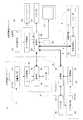
以下、図面を参照してこの発明の実施例1を説明する。図1は、各実施例に係るX線撮影装置の概略図であり、図2は、各実施例に係るX線撮影装置のブロック図であり、図3は、X線管にコリメータランプを配設したときの概略図である。後述する実施例2〜5も含めて、本実施例1では、放射線としてX線を例に採って説明するとともに、放射線装置としてX線撮影を行うX線撮影装置を例に採って説明する。
後述する実施例2〜5も含めて、図1に示すように、本実施例1に係るX線撮影装置1は、天井に沿って移動可能にX線管22を懸垂支持するX線管懸垂ユニット2、被検体Mを立位姿勢の状態でX線撮影を行うX線撮影スタンドユニット3、被検体Mを臥位姿勢の状態でX線撮影を行う臥位テーブルユニット4および被検体MのX線画像に対して画像処理を行う画像処理ユニット5(図1では図示省略)とを備えている。図2に示すように、X線管懸垂ユニット2、X線撮影スタンドユニット3、臥位テーブルユニット4および画像処理ユニット5は互いに通信ケーブル6によって電気的に接続されており、この通信ケーブル6によって、X線管懸垂ユニット2、X線撮影スタンドユニット3、臥位テーブルユニット4および画像処理ユニット5は互いに通信可能に構成される。 As shown in FIG. 1 including Examples 2 to 5 to be described later, the
X線管懸垂ユニット2は、図1に示すように、天井に沿って移動可能で上下に伸縮可能な支柱21と、その支柱21により支持され向きが調整可能なX線管22とを備えている。また、X線管懸垂ユニット2は、図2に示すように、X線管22の位置や角度を検出する位置検出部23と、位置検出部23により得られた位置情報のアナログ電圧をディジタルデータに変換するA/D変換器24とを備えている。その他に、X線管懸垂ユニット2は、メモリ部25と入力部26と出力部27と制御部28と照射野ランプ(コリメータランプ)29とを備えている。具体的な制御部28およびコリメータランプ29の構造については後述する。X線管22は、この発明における放射線照射手段に相当し、制御部28は、この発明における光源点灯制御手段,点灯時間制限手段および光源種類判別手段に相当し、照射野ランプ(コリメータランプ)29は、この発明における光源に相当する。 As shown in FIG. 1, the X-ray
X線撮影スタンドユニット3は、図1に示すように、被検体Mを立位姿勢で支持する立位スタンド31と、この立位スタンド31に搭載され上下に昇降移動可能なフラットパネル型X線検出器(FPD)32とを備えている。また、X線撮影スタンドユニット3は、図2に示すように、FPD32の位置を検出する位置検出部33と、位置検出部33により得られた位置情報のアナログ電圧をディジタルデータに変換するA/D変換器34とを備えている。その他に、X線撮影スタンドユニット3は、メモリ部35と制御部36とを備えている。なお、X線管懸垂ユニット2と同様に、X線撮影スタンドユニット3は入力部と出力部とを備えてもよい。また、X線撮影スタンドユニット3にメモリ部35や制御部36を備えずに、X線管懸垂ユニット2の制御部28が、X線撮影スタンドユニット3のFPD32などを直接的に制御してもよい。 As shown in FIG. 1, the X-ray
臥位テーブルユニット4は、図1に示すように、被検体Mを臥位姿勢で載置する臥位テーブル41と、この臥位テーブル41に搭載され水平移動可能なフラットパネル型X線検出器(FPD)42とを備えている。また、臥位テーブルユニット4は、図2に示すように、FPD42の位置を検出する位置検出部43と、位置検出部43により得られた位置情報のアナログ電圧をディジタルデータに変換するA/D変換器44とを備えている。その他に、臥位テーブルユニット4は、メモリ部45と制御部46とを備えている。なお、X線管懸垂ユニット2と同様に、臥位テーブルユニット4は入力部と出力部とを備えてもよい。また、臥位テーブルユニット4にメモリ部45や制御部46を備えずに、X線管懸垂ユニット2の制御部28が、臥位テーブルユニット4のFPD42などを直接的に制御してもよい。 As shown in FIG. 1, the lying
画像処理ユニット5は、図2に示すように、X線撮影スタンドユニット3のFPD32あるいは臥位テーブルユニット4のFPD42で得られたX線出力信号に基づいて画像処理を行ってX線画像(X線撮影画像)を作成する画像処理部51を備えている。その他に、画像処理ユニット5は、X線画像を書き込んで記憶するメモリ部52を備えている。なお、X線管懸垂ユニット2と同様に、画像処理ユニット5は入力部と出力部とを備えてもよい。また、画像処理ユニット5にメモリ部52を備えずに、X線管懸垂ユニット2のメモリ部25に、X線画像を書き込んで記憶するように構成してもよい。 As shown in FIG. 2, the
X線管懸垂ユニット2の支柱21は、天井に沿って敷設されたレールRに沿って移動可能である。図1の紙面の奥行き方向にも沿ってレールRは敷設され、奥行き方向にも沿って支柱21は移動可能である。この支柱21は伸縮可能に構成され、この支柱21によってX線管22が支持されることにより、X線管22は水平/昇降移動可能である。また、X線管22は向きが調整可能である。したがって、X線撮影スタンドユニット3の立位スタンド31の方に向けて、図1の実線に示すようにX線管22を水平/昇降移動させて向きを調整して、立位姿勢でX線撮影を行うことが可能である。また、臥位テーブルユニット4の臥位テーブル41の方に向けて、図1の2点鎖線に示すようにX線管22を水平/昇降移動させて向きを調整して、臥位姿勢でX線撮影を行うことも可能である。 The
図2に示すように、X線管22には位置検出部23が配設され、その位置検出部23によってX線管22の位置や角度を検出する。位置検出部23は例えばポテンショメータで構成され、X線管22の移動や回転移動に伴ってポテンショメータの抵抗値が変化し、その抵抗値に伴って基準電圧に対して出力電圧が変化する。この出力電圧はアナログ電圧であって、ポテンショメータにより得られた位置情報(角度も含む)のアナログ電圧をA/D変換器24に送り込み、A/D変換器24はアナログ電圧をディジタルデータに変換する。 As shown in FIG. 2, a
X線管懸垂ユニット2のメモリ部25は、制御部28を介して、撮影毎のX線画像取得エリアや各撮影における撮影位置を書き込んで記憶し、適宜必要に応じて読み出す。X線管懸垂ユニット2のメモリ部25や、X線撮影スタンドユニット3のメモリ部35や、臥位テーブルユニット4のメモリ部45や、画像処理ユニット5のメモリ部52は、ROM(Read-only Memory)やRAM(Random-Access Memory)などに代表される記憶媒体で構成されている。 The
X線管懸垂ユニット2の入力部26は、オペレータが入力したデータや命令を制御部28に送り込む。入力部26は、マウスやキーボードやジョイスティックやトラックボールやタッチパネルなどに代表されるポインティングデバイスで構成されている。本実施例1では、点灯ボタン(図示省略)を押下することで、コリメータランプ29を所定時間だけ点灯させ、当該所定時間が経過するとコリメータランプ29が自動的に消灯する。 The
X線管懸垂ユニット2の出力部27は、モニタなどに代表される表示部やプリンタなどで構成されている。出力部27が表示部の場合には出力表示し、出力部27がプリンタの場合には出力印刷する。また、上述した点灯ボタンを搭載したタッチパネルで出力部27を構成し、このタッチパネルをX線管22に取り付けてもよい。このように出力部27に入力部26の機能を搭載してもよい。 The
X線管懸垂ユニット2の制御部28は、X線管懸垂ユニット2を構成する各部分を統括制御する。X線管懸垂ユニット2の制御部28や、X線撮影スタンドユニット3の制御部36や、臥位テーブルユニット4の制御部46や、画像処理ユニット5の画像処理部51は、中央演算処理装置(CPU)などを搭載した制御基板で構成されている。後述する実施例2〜5も含めて、本実施例1では、コリメータランプ29の点灯を制御する光源点灯制御手段の機能、さらには、装置本体に接続されたコリメータランプ29の種類を判別する光源種類判別手段の機能を制御部28は有している。また、後述する実施例2も含めて、本実施例1では、所定の温度以下になるようにコリメータランプ29の点灯時間を制限する点灯時間制限手段の機能、さらには、光源種類判別手段の機能による判別の結果に基づいて、点灯時間制限手段が制限する点灯時間を変更する機能を制御部28は有している。 The
X線管懸垂ユニット2のコリメータランプ29は、図3に示すようにX線管22からのX線の照射野を制御するコリメータ(X線絞り)22aに内蔵されている。具体的には、照射野のサイズが変更可能なリーフ22bおよび反射鏡22cを備え、コリメータランプ29から照射された可視光(光)を反射鏡22cによって反射させてリーフ22bを通るように構成される。コリメータ22aのリーフ22bを操作することによりコリメータランプ29から照射される照射野(「採光野」とも呼ばれる)のサイズを自在に設定することができる。このように、コリメータランプ29は、コリメータ22aのリーフ22bにより調整された照射野全体を可視光(光)で照らす。後述する実施例2〜5も含めて、本実施例1では、コリメータランプ29は、ハロゲンランプまたは発光ダイオード(LED)からなり、いずれか一方に切り替えるように構成されている。 The
図1に示すように、X線撮影スタンドユニット3の立位スタンド31は床面に対して設置されている。X線撮影スタンドユニット3のFPD32は、立位スタンド31に沿って上下に昇降移動可能である。一方、臥位テーブルユニット4の臥位テーブル41も床面に対して設置されている。臥位テーブルユニット4のFPD42は、臥位テーブル41内を水平移動可能である。 As shown in FIG. 1, the standing
図2に示すように、X線撮影スタンドユニット3のFPD32には位置検出部33が配設され、その位置検出部33によってFPD32の位置を検出する。一方、臥位テーブルユニット4のFPD42にも位置検出部43が配設され、その位置検出部43によってFPD42の位置を検出する。X線管懸垂ユニット2の位置検出部23と同様に、X線撮影スタンドユニット3の位置検出部33や、臥位テーブルユニット4の位置検出部43もポテンショメータで構成され、FPD32,42の移動に伴ってポテンショメータの抵抗値が変化し、その抵抗値に伴って基準電圧に対して出力電圧が変化する。この出力電圧はアナログ電圧であって、ポテンショメータにより得られた位置情報のアナログ電圧を、X線撮影スタンドユニット3の場合にはA/D変換器34に送り込み、臥位テーブルユニット4の場合にはA/D変換器44に送り込み、A/D変換器34,44はアナログ電圧をディジタルデータにそれぞれ変換する。また、X線撮影スタンドユニット3や臥位テーブルユニット4のポテンショメータにより得られた位置情報のアナログ電圧を、通信ケーブル6を介してX線管懸垂ユニット2にも送り込む。 As shown in FIG. 2, a
X線撮影スタンドユニット3のメモリ部35は、X線撮影におけるFPD32の上端位置および下端位置を書き込んで記憶し、適宜必要に応じて読み出す。一方、臥位テーブルユニット4のメモリ部45は、X線撮影におけるFPD42の左端位置および右端位置を書き込んで記憶し、適宜必要に応じて読み出す。 The
X線撮影スタンドユニット3の制御部36は、X線撮影スタンドユニット3を構成する各部分を統括制御し、臥位テーブルユニット4の制御部46は、臥位テーブルユニット4を構成する各部分を統括制御する。 The
X線管懸垂ユニット2の制御部28と、X線撮影スタンドユニット3の制御部36とを、通信ケーブル6によって電気的に接続し、X線管懸垂ユニット2の制御部28と、臥位テーブルユニット4の制御部46とを、通信ケーブル6によって電気的に接続し、X線管懸垂ユニット2の制御部28と、画像処理ユニット5の画像処理部51とを、通信ケーブル6によって電気的に接続する。このように接続することによって、X線管懸垂ユニット2、X線撮影スタンドユニット3、臥位テーブルユニット4および画像処理ユニット5を互いに通信可能に構成する。その他に、各制御部28,36,46は、X線管22やFPD32,42を駆動制御し、図示を省略するモータを各制御部28,36,46が制御することによりX線管22やFPD32,42をモータ駆動させる。このモータ駆動により、X線管22やFPD32,42を所望の位置に制御し、X線管22の向きを所望の角度にて調整することができる。 The
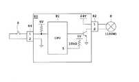
次に、本実施例1に係る制御部28の具体的な構造および制御部28による具体的な制御について、図4を参照して説明する。図4は、光源種類判別手段の説明に供する、実施例1に係る制御基板および周辺の回路である。 Next, a specific structure of the
制御部28(図2を参照)は、図4に示すように、光源種類判別手段の機能を有した制御基板70で構成され、光源点灯制御手段の機能および点灯時間制限手段の機能を有した中央演算処理装置(CPU)71を制御基板70に搭載して構成されている。本実施例1では、図4に示すように1つの制御基板70が、ハロゲンランプHおよび発光ダイオード(LED)Lの両方に接続可能で、いずれか一方に切り替えるように構成されている。図4では、CPU71は、光源点灯制御手段の機能に専ら用いられており、点灯時間制限手段の機能を組み込んで内蔵している。 As shown in FIG. 4, the control unit 28 (see FIG. 2) includes a
具体的には、制御基板70は装置(図1および図2ではX線撮影装置1)本体に搭載されている。そして、制御基板70は、図2に示すように制御部28としてX線撮影装置1を構成する各部分に電気的に接続されている。 Specifically, the
図4に示すように、制御基板70は、ハロゲンランプ用コネクタ72を介してハロゲンランプHに電気的に接続され、LED用コネクタ73を介して発光ダイオード(LED)Lに電気的に接続されている。また、制御基板70はスイッチ用コネクタ74を介してランプ点灯スイッチSに電気的に接続されている。ハロゲンランプ用コネクタ72やスイッチ用コネクタ74は2つのピン(接続端子)を有し、LED用コネクタ73は4つのピン(接続端子)を有している。 As shown in FIG. 4, the
ハロゲンランプ用コネクタ72の1番ピン(図4では「1」で表記)および2番ピン(図4では「2」で表記)はハロゲンランプHにつながっており、当該ハロゲンランプ用コネクタ72を制御基板70に挿すことで、当該1番ピンは24Vの直流電源に電気的に接続され、当該2番ピンはトランジスタを介してCPU71に電気的に接続される。また、24Vの直流電源はAC/DC変換基板(図示省略)に電気的に接続されており、交流を24Vの直流電圧に変換した後にハロゲンランプHに電力を供給する。なお、ハロゲンランプHの場合には交流による点灯も可能であるので、交流電源を直接に取り込んでもよい。 Pin 1 (indicated by “1” in FIG. 4) and pin 2 (indicated by “2” in FIG. 4) of the
スイッチ用コネクタ74の1番ピン(図4では「1」で表記)および2番ピン(図4では「2」で表記)はランプ点灯スイッチSにつながっており、当該スイッチ用コネクタ74を制御基板70に挿すことで、当該1番ピンは、途中で5Vの直流電源に接続された抵抗に電気的に接続され、CPU71に電気的に接続される。また、当該2番ピンは接地される。 The first pin (indicated by “1” in FIG. 4) and the second pin (indicated by “2” in FIG. 4) of the
LED用コネクタ73の1番ピン(図4では「1」で表記)および2番ピン(図4では「2」で表記)は発光ダイオード(LED)Lにつながっており、当該LED用コネクタ73を制御基板70に挿すことで、当該1番ピンは14Vの直流電源に電気的に接続され、当該2番ピンはトランジスタを介してCPU71に電気的に接続される。また、14Vの直流電源はAC/DC変換基板(図示省略)に電気的に接続されており、交流を14Vの直流電圧に変換した後に発光ダイオード(LED)Lに電力を供給する。 The first pin (indicated by “1” in FIG. 4) and the second pin (indicated by “2” in FIG. 4) of the
なお、LED用コネクタ73の3番ピン(図4では「3」で表記)および4番ピン(図4では「4」で表記)はケーブルによって短絡(ショート)するように構成されている。LED用コネクタ73を制御基板70に挿すことで、当該3番ピンは、途中で5Vの直流電源に接続された高抵抗(例えば10kΩ)に電気的に接続され、CPU71の5番ピン(図4では「5」で表記)に電気的に接続される。また、当該4番ピンは接地される。 The third pin (indicated by “3” in FIG. 4) and the fourth pin (indicated by “4” in FIG. 4) of the
CPU71の5番ピンは、電圧が3.7V〜5VのときにはHighロジックになり、電圧が0V〜0.7VのときにはLowロジックになる。ロジックを検知する電圧に閾値のマージンを持たせているのは、Highロジックの場合には電圧降下やノイズを考慮するためであり、Lowロジックの場合にはノイズを考慮するためである。ロジックを検知する電圧に閾値のマージンを持たせることにより、Highロジックの場合には電圧降下やノイズがあったとしても3.7V〜5Vの範囲内にすることができ、Lowロジックの場合にはノイズがあったとしても0V〜0.7Vの範囲内にすることができる。よって、電圧降下やノイズがあったとしても誤検出を防止することができる。なお、ロジックを検知する電圧の閾値の範囲については、上述した範囲(Highロジックを検知する電圧が3.7V〜5Vの範囲,Lowロジックを検知する電圧が0V〜0.7Vの範囲)に限定されない。 The fifth pin of the
制御基板70にハロゲンランプHを接続し、発光ダイオード(LED)Lを接続しない場合には、発光ダイオード(LED)LにつながるLED用コネクタ73を制御基板70に挿し込まないので、CPU71の5番ピンは、途中で接続された5Vの直流電源によって、ほぼ5VにプルアップされてHighロジックになる。なお、当該5Vの直流電源に接続された抵抗によって多少の電圧降下が生じるが、当該抵抗が例えば10kΩ程度の高抵抗であるので、当該抵抗に流れる電流はマイクロアンペア(μA)オーダとなり電圧降下を無視することができる。このように、制御基板70に接続された光源がハロゲンランプHである場合には、CPU71の5番ピンがHighロジックになったのを検出することにより、制御基板70に接続された光源がハロゲンランプHであるのを検出して、検出された当該光源の種類がハロゲンランプHであるのを自動的に判別する。 When the halogen lamp H is connected to the
逆に、制御基板70にハロゲンランプHを接続せず、発光ダイオード(LED)Lを接続する場合には、発光ダイオード(LED)LにつながるLED用コネクタ73を制御基板70に挿すと、CPU71の5番ピンは、LED用コネクタ73につけられたケーブルによって3番ピンと4番ピンとの間がショートされた結果、接地された4番ピンによりLowロジックに落ちる。このように、制御基板70に接続された光源が発光ダイオード(LED)Lである場合には、CPU71の5番ピンがLowロジックになったのを検出することにより、制御基板70に接続された光源が発光ダイオード(LED)Lであるのを検出して、検出された当該光源の種類が発光ダイオード(LED)Lであるのを自動的に判別する。 Conversely, when the light emitting diode (LED) L is connected to the
続いて、本実施例1に係る制御部28による具体的な制御について説明する。制御部28による光源の点灯時間を制限する具体的な制御方式については、例えば以下の制御方式1〜制御方式4が挙げられる。 Subsequently, specific control by the
[制御方式1]
上述した特許文献1:特開2012−55421号公報のように、温度上昇や温度下降を疑似温度カウンターとしてカウントアップあるいはカウントダウンし、そのカウント値が設定値を超えるとコリメータランプの点灯を中止して、外装温度が高温になるのを防止していた。[Control method 1]
As described in Patent Document 1: Japanese Patent Application Laid-Open No. 2012-55421, a temperature rise or a temperature fall is counted up or down as a pseudo temperature counter, and when the count value exceeds a set value, the collimator lamp is turned off. The exterior temperature was prevented from becoming high.
ハロゲンランプを使用する場合には、例えば、点灯中には1秒につき2カウントをカウントアップし、消灯中には1秒につき1カウントをカウントダウンする。つまり、点灯時間の2倍の時間でハロゲンランプが消灯すると、点灯前のカウント値を維持する。なお、“0”までカウントダウンしたらマイナスまではカウントダウンせず、“0”を維持する。このカウント値が、例えば600カウントになったら点灯を中止する。 When using a halogen lamp, for example, 2 counts up per second during lighting, and 1 count down per second during lighting off. That is, when the halogen lamp is turned off in twice the lighting time, the count value before lighting is maintained. Note that if the countdown is performed to “0”, the countdown to minus is not performed and “0” is maintained. When this count value reaches, for example, 600 counts, lighting is stopped.
上記の例では、ハロゲンランプの点灯時間と消灯時間とが1:2を維持している限り、温度制限のようなプロテクトが働かずにコリメータランプが強制的に消灯することはない。逆に、例えば5分(=300秒)連続して点灯する場合には、2カウント/秒×300秒=600カウントとなり、600カウントに到達するので、プロテクトが働きコリメータランプが強制的に消灯する、ということになる。 In the above example, the collimator lamp is not forcibly turned off without protection such as temperature limitation as long as the halogen lamp lighting time and lighting time are maintained at 1: 2. On the other hand, for example, when lighting continuously for 5 minutes (= 300 seconds), it becomes 2 counts / second × 300 seconds = 600 counts and reaches 600 counts, so that the protection is activated and the collimator lamp is forcibly turned off. ,It turns out that.
この例は、ハロゲンランプを使用したときにおける、温度上昇の勾配が温度下降の勾配よりも2倍急峻である場合の演算である。以下、本明細書では、この演算による制御方式を「制御方式1」と呼ぶ。LEDを使用する場合には、制御方式1によって下記のように点灯時間制限手段が制限する点灯時間を変更する。 This example is a calculation when the gradient of temperature rise is twice as steep as the gradient of temperature drop when a halogen lamp is used. Hereinafter, in this specification, the control method based on this calculation is referred to as “
例えば、ハロゲンランプでは600カウントになったら点灯を禁止していたが、LEDでは1200カウントになったら点灯を禁止する。あるいは、ハロゲンランプでは点灯1秒につき2カウントをカウントアップしていたが、LEDでは点灯1秒につき1カウントをカウントアップする。 For example, the halogen lamp prohibits lighting when the count reaches 600, but the LED prohibits lighting when the count reaches 1200. Alternatively, the halogen lamp counts up 2 counts per second, but the LED counts up 1 count per second.
上述した特許文献1:特開2012−55421号公報のような制御方式1は複雑な計算・制御となるが、CPUによって実現可能である。制御方式1のような複雑な計算・制御をするものでなくとも、例えば以下のような単純な制御方式2〜制御方式4でもよい。 The
[制御方式2]
ハロゲンランプを使用する場合には、例えば5分連続して点灯すると、その後に温度制限をかけて10分間点灯を禁止する。以下、本明細書では、この制御方式を「制御方式2」と呼ぶ。LEDを使用する場合には、制御方式2によって下記のように点灯時間制限手段が制限する点灯時間を変更する。[Control method 2]
When a halogen lamp is used, for example, if it is lit continuously for 5 minutes, then it is prohibited to light for 10 minutes with a temperature limit. Hereinafter, this control method is referred to as “
例えば、ハロゲンランプでは5分連続して点灯した後に温度制限をかけていたが、LEDでは10分連続して点灯した後に温度制限をかける。 For example, a halogen lamp has been subjected to temperature limitation after being lit continuously for 5 minutes, whereas an LED is subjected to temperature limitation after being lit continuously for 10 minutes.
[制御方式3]
ハロゲンランプを使用する場合には、例えば5分連続して点灯すると、その後に温度制限をかけて装置を再起動するまでに点灯を禁止する。言い換えれば、5分連続点灯後に装置を再起動すれば温度制限のようなプロテクトが解除される。したがって、温度上昇の勾配が温度下降の勾配よりも2倍急峻である場合には、温度制限をかけた直後から10分以内に装置を再起動しないように技師などの使用者が留意する。以下、本明細書では、この制御方式を「制御方式3」と呼ぶ。LEDを使用する場合には、制御方式3によって下記のように点灯時間制限手段が制限する点灯時間を変更する。[Control method 3]
When using a halogen lamp, for example, if it is lit continuously for 5 minutes, the lighting is prohibited before the device is restarted after the temperature is limited. In other words, if the device is restarted after 5 minutes of continuous lighting, the protection such as temperature limitation is canceled. Therefore, when the temperature increase gradient is twice as steep as the temperature decrease gradient, a user such as an engineer takes care not to restart the apparatus within 10 minutes immediately after the temperature limit is applied. Hereinafter, this control method is referred to as “
例えば、ハロゲンランプでは5分連続して点灯した後に温度制限をかけていたが、制御方式2と同様に、LEDでは10分連続して点灯した後に温度制限をかける。 For example, in the case of a halogen lamp, the temperature is limited after being lit continuously for 5 minutes, but in the same manner as in the
[制御方式4]
ハロゲンランプを使用する場合には、点灯ボタン(図示省略)の1回押下で例えば30秒点灯し、10回押下することにより30秒/回×10回=300秒となり、5分(=300秒)連続して点灯する。その5分連続点灯後の10分間は点灯ボタンの1回押下で10秒しか点灯しないように温度制限をかける。以下、本明細書では、この制御方式を「制御方式4」と呼ぶ。LEDを使用する場合には、制御方式4によって下記のように点灯時間制限手段が制限する点灯時間を変更する。[Control method 4]
When a halogen lamp is used, for example, when the lighting button (not shown) is pressed once, it is lit for 30 seconds, and when it is pressed 10 times, 30 seconds / times × 10 times = 300 seconds, 5 minutes (= 300 seconds) ) Lights continuously. For 10 minutes after the 5 minutes of continuous lighting, the temperature is limited so that only 10 seconds can be lit by pressing the lighting button once. Hereinafter, this control method is referred to as “
例えば、ハロゲンランプでは5分連続点灯後の10分間は点灯ボタンの1回押下で10秒しか点灯しないように温度制限をかけていたが、LEDでは5分連続点灯後の10分間は点灯ボタンの1回押下で25秒まで点灯可能になるように温度制限をかける。 For example, in the case of a halogen lamp, the temperature is limited so that only 10 seconds can be lit by pressing the lighting button once for 10 minutes after 5 minutes of continuous lighting. Temperature is limited so that it can be lit up to 25 seconds when pressed once.
上述の構成を備えた本実施例1に係るX線撮影装置1によれば、放射線(各実施例ではX線)の照射野に可視光(光)を照射する光源(各実施例ではコリメータランプ29)や、当該光源(コリメータランプ29)の点灯を制御する光源点灯制御手段(図4ではCPU71)の他に、所定の温度以下になるように光源(コリメータランプ29)の点灯時間を制限する(図4ではCPU71に組み込まれた)点灯時間制限手段と、装置本体に接続された光源の種類を判別する光源種類判別手段(図4では制御基板70)とを備えている。(CPU71に組み込まれた)点灯時間制限手段が所定の温度以下になるように光源(コリメータランプ29)の点灯時間を制限することにより、装置外装の温度が過熱しないようにする。光源種類判別手段(制御基板70)での装置本体に接続された光源の種類を判別することによる判別の結果に基づいて、(CPU71に組み込まれた)点灯時間制限手段が制限する点灯時間を光源点灯制御手段(CPU71)が変更することより、出荷時の組み立て者や保守時のサービスマンなどの人間が手動で設定する必要がなく、光源(コリメータランプ29)の切り替え設定を自動的に行うことができる。また、光源種類判別手段(制御基板70)による判別の結果に基づいて(CPU71に組み込まれた)点灯時間制限手段が制限する点灯時間を変更するので、誤設定のリスクを防止することができる。例えば、発熱の大きい種類の光源(例えばハロゲンランプ)が実際に接続されていても、当該光源の種類を接続対象として自動的に判別することで、点灯時間を短く制限して過熱を防止する。逆に、発熱の小さい種類の光源(例えばLED)が実際に接続されていても、当該光源の種類を接続対象として自動的に判別することで、点灯時間を長く設定して長時間に連続して使用する。よって、発熱の大きい種類の光源を用いて外装温度の過熱の可能性がある場合には過熱を防止し、発熱の小さい種類の光源を用いて外装温度の過熱の可能性がない場合には長時間に連続して使用することが可能となる。その結果、誤設定のリスクを防止し、光源の切り替え設定を自動的に行うことができる。 According to the
本実施例1では、光源種類判別手段は、光源が接続されたことを検出する。図4に示すように、制御基板70に接続された光源(図4ではハロゲンランプHまたは発光ダイオード(LED)L)を検出する(図4ではCPU71の5番ピンがHighロジックまたはLowロジックになったのを検出する)ことにより、検出された当該光源の種類を判別する。本実施例1の場合には、制御基板を1つ用意して、装置本体に搭載された当該制御基板に光源を接続するだけで、光源の種類の判別を実現することができる。 In the first embodiment, the light source type determination unit detects that the light source is connected. As shown in FIG. 4, the light source (halogen lamp H or light emitting diode (LED) L in FIG. 4) connected to the
次に、図面を参照してこの発明の実施例2を説明する。図5は、光源種類判別手段の説明に供する、実施例2に係るハロゲンランプ用制御基板(ハロゲンランプ点灯用回路)および周辺の回路であり、図6は、光源種類判別手段の説明に供する、実施例2に係るLED用制御基板(LED点灯用回路)および周辺の回路である。本実施例2では、図2のブロック図も含めて、上述した実施例1と同じ図1に示すX線撮影装置1を用いてX線撮影を行っている。 Next,
上述した実施例1では、光源種類判別手段は、図4に示すような制御基板70であったが、本実施例2では、ハロゲンランプを点灯させるための制御基板(ハロゲンランプ用制御基板)と、LEDを点灯させるための制御基板(LED用制御基板)とが別々にあって、それぞれに同じCPU(光源点灯制御手段)を搭載して構成されている。 In the first embodiment described above, the light source type discriminating means is the
具体的には、図5に示すハロゲンランプ用制御基板(ハロゲンランプ点灯用回路)80または図6に示すLED用制御基板(LED点灯用回路)90のいずれか一方の制御基板が装置(図1および図2ではX線撮影装置1)本体に搭載されている。そして、装置本体に搭載された方の制御基板は、図2に示すように制御部28としてX線撮影装置1を構成する各部分に電気的に接続されている。 Specifically, either one of the halogen lamp control board (halogen lamp lighting circuit) 80 shown in FIG. 5 or the LED control board (LED lighting circuit) 90 shown in FIG. And in FIG. 2, it mounts in the X-ray imaging apparatus 1) main body. The control board mounted on the apparatus main body is electrically connected to each part of the
先ず、ハロゲンランプ用制御基板80について、図5を参照して説明する。制御部28(図2を参照)は、図5に示すように、光源種類判別手段の機能を有したハロゲンランプ用制御基板80で構成され、光源点灯制御手段の機能および点灯時間制限手段の機能を有した中央演算処理装置(CPU)81をハロゲンランプ用制御基板80に搭載して構成されている。本実施例2では、図5に示すようにハロゲンランプ用制御基板80がハロゲンランプHのみに電気的に接続されて構成されている。 First, the halogen
具体的には、ハロゲンランプ用制御基板80は、ハロゲンランプ用コネクタ82を介してハロゲンランプHに電気的に接続されている。また、ハロゲンランプ用制御基板80はスイッチ用コネクタ84を介してランプ点灯スイッチSに電気的に接続されている。ハロゲンランプ用コネクタ82やスイッチ用コネクタ84は2つのピン(接続端子)を有している。 Specifically, the halogen
ハロゲンランプ用コネクタ82の1番ピン(図5では「1」で表記)および2番ピン(図5では「2」で表記)はハロゲンランプHにつながっている。上述した実施例1と相違して、ハロゲンランプ用制御基板80はハロゲンランプHのみに電気的に接続されている。当該ハロゲンランプ用コネクタ82をハロゲンランプ用制御基板80に挿すと、当該1番ピンは24Vの直流電源に電気的に接続され、当該2番ピンはトランジスタを介してCPU81に電気的に接続される。 The first pin (indicated by “1” in FIG. 5) and the second pin (indicated by “2” in FIG. 5) of the
スイッチ用コネクタ84の1番ピン(図5では「1」で表記)および2番ピン(図5では「2」で表記)はランプ点灯スイッチSにつながっており、上述した実施例1と同様に、当該スイッチ用コネクタ84をハロゲンランプ用制御基板80に挿すことで、当該1番ピンは、途中で5Vの直流電源に接続された抵抗に電気的に接続され、CPU81に電気的に接続される。また、当該2番ピンは接地される。 The first pin (indicated by “1” in FIG. 5) and the second pin (indicated by “2” in FIG. 5) of the
また、CPU81の5番ピン(図5では「5」で表記)は、5Vの直流電源に接続された高抵抗(例えば10kΩ)に電気的に接続されている。CPU81がハロゲンランプ用制御基板80に搭載された際には、CPU81の5番ピンが、5Vの直流電源によって、ほぼ5VにプルアップされてHighロジックになる。上述した実施例1でも述べたように、当該5Vの直流電源に接続された抵抗によって多少の電圧降下が生じるが、当該抵抗が例えば10kΩ程度の高抵抗であるので、当該抵抗に流れる電流はマイクロアンペア(μA)オーダとなり電圧降下を無視することができる。このように、ハロゲンランプ用制御基板80にCPU81が搭載された場合には、CPU81の5番ピンがHighロジックになったのを検出することにより、ハロゲンランプ用制御基板80にCPU81が搭載されたのを検出して、検出された当該光源の種類がハロゲンランプHであるのを自動的に判別する。 Further, the fifth pin (indicated by “5” in FIG. 5) of the
続いて、LED用制御基板(LED点灯用回路)90について、図6を参照して説明する。制御部28(図2を参照)は、図6に示すように、光源種類判別手段の機能を有したLED用制御基板90で構成され、光源点灯制御手段の機能および点灯時間制限手段の機能を有した中央演算処理装置(CPU)91をLED用制御基板90に搭載して構成されている。本実施例2では、図6に示すようにLED用制御基板90が発光ダイオード(LED)Lのみに電気的に接続されて構成されている。 Next, the LED control board (LED lighting circuit) 90 will be described with reference to FIG. As shown in FIG. 6, the control unit 28 (see FIG. 2) is composed of an
具体的には、LED用制御基板90は、LED用コネクタ93を介して発光ダイオード(LED)Lに電気的に接続されている。また、LED用制御基板90はスイッチ用コネクタ94を介してランプ点灯スイッチSに電気的に接続されている。スイッチ用コネクタ94は2つのピン(接続端子)を有しており、本実施例2では、LED用コネクタ93は2つのピン(接続端子)を有している。 Specifically, the
LED用コネクタ93の1番ピン(図6では「1」で表記)および2番ピン(図6では「2」で表記)は発光ダイオード(LED)Lにつながっている。上述した実施例1と相違して、LED用制御基板90は発光ダイオード(LED)Lのみに電気的に接続されている。当該LED用コネクタ93をLED用制御基板90に挿すと、当該1番ピンは14Vの直流電源に電気的に接続され、当該2番ピンはトランジスタを介してCPU91に電気的に接続される。また、上述した実施例1と同様に、14Vの直流電源はAC/DC変換基板(図示省略)に電気的に接続されており、交流を14Vの直流電圧に変換した後に発光ダイオード(LED)Lに電力を供給する。 The first pin (indicated by “1” in FIG. 6) and the second pin (indicated by “2” in FIG. 6) of the
スイッチ用コネクタ94の1番ピン(図6では「1」で表記)および2番ピン(図6では「2」で表記)はランプ点灯スイッチSにつながっており、上述した実施例1や図5のハロゲンランプ用制御基板80と同様に、当該スイッチ用コネクタ94をLED用制御基板90に挿すことで、当該1番ピンは、途中で5Vの直流電源に接続された抵抗に電気的に接続され、CPU91に電気的に接続される。また、当該2番ピンは接地される。 The first pin (indicated by “1” in FIG. 6) and the second pin (indicated by “2” in FIG. 6) of the
また、CPU91の5番ピン(図6では「5」で表記)は接地されている。CPU91がLED用制御基板90に搭載された際には、CPU91の5番ピンが、接地によってプルダウンされてLowロジックになる。このように、LED用制御基板90にCPU91が搭載された場合には、CPU91の5番ピンがLowロジックになったのを検出することにより、LED用制御基板90にCPU91が搭載されたのを検出して、検出された当該光源の種類が発光ダイオード(LED)Lであるのを自動的に判別する。 Further, the fifth pin (indicated by “5” in FIG. 6) of the
なお、図5および図6ではCPUについて、互いに別々の符号(81,91)を付したが、実際には同一のCPUを、図5に示すハロゲンランプ用制御基板(ハロゲンランプ点灯用回路)80および図6に示すLED用制御基板(LED点灯用回路)90で共用している。したがって、ハロゲンランプ用制御基板80およびLED用制御基板90において、CPUの同一の1つのピンのロジックを反対にしておくことによって、CPUがどちらの基板に搭載されたのかを自動的に検出することができる。 5 and FIG. 6, the CPUs are given different reference numerals (81, 91), but actually the same CPU is connected to the halogen lamp control board (halogen lamp lighting circuit) 80 shown in FIG. And the LED control board (LED lighting circuit) 90 shown in FIG. Therefore, in the halogen
本実施例2においても、上述した実施例1でも述べた制御方式1〜制御方式4による制御を行う。 Also in the second embodiment, control is performed by the
上述の構成を備えた本実施例2に係るX線撮影装置1の作用・効果については、上述した実施例1と同じであるので、説明を省略する。 Since the operations and effects of the
本実施例2では、光源種類判別手段は、図5および図6に示すように、光源点灯制御手段(CPU)が光源(図5および図6ではハロゲンランプHまたは発光ダイオード(LED)L)を点灯させるための当該光源専用の制御基板(図5および図6ではハロゲンランプ用制御基板80およびLED用制御基板90)に搭載されたことを検出する(図5および図6ではCPUの5番ピンがHighロジックまたはLowロジックになったのを検出する)。本実施例2の場合には、光源の種類の数だけ光源専用の制御基板(光源専用の点灯用回路)を用意して、それぞれに同じ光源点灯制御手段(CPU)を搭載するだけで、光源の種類の判別を実現することができる。 In the second embodiment, as shown in FIGS. 5 and 6, the light source type discriminating means is such that the light source lighting control means (CPU) uses the light source (the halogen lamp H or the light emitting diode (LED) L in FIG. 5 and FIG. 6). It is detected that the light source is mounted on the control board dedicated to the light source (in FIG. 5 and FIG. 6, the halogen
次に、図面を参照してこの発明の実施例3を説明する。本実施例3では、図2のブロック図も含めて、上述した実施例1,2と同じ図1に示すX線撮影装置1を用いてX線撮影を行っている。 Next,
上述した実施例1,2では、光源種類判別手段(各実施例1,2では制御基板)による判別の結果に基づいて点灯時間制限手段(各実施例1,2ではCPU)が制限する点灯時間を変更していたが、本実施例3では、光源種類判別手段(制御基板)による判別の結果により光源がLEDのような半導体光源である場合に、点灯時間制限手段(CPU)を無効にしている。これは、LEDの消費電力が10W〜20W程度で、ハロゲンランプの消費電力の1/10〜1/5であって、点灯時間制限手段(CPU)自体を無効にすることでLEDを無制限に点灯させても過熱しにくいからである。 In the first and second embodiments described above, the lighting time limited by the lighting time limiting means (CPU in each of the first and second embodiments) based on the determination result by the light source type determining means (control board in the first and second embodiments). In the third embodiment, when the light source is a semiconductor light source such as an LED as a result of determination by the light source type determination means (control board), the lighting time limit means (CPU) is disabled. Yes. The power consumption of the LED is about 10W to 20W, 1/10 to 1/5 of the power consumption of the halogen lamp, and the LED is turned on indefinitely by disabling the lighting time limit means (CPU) itself. It is because it is hard to overheat even if it makes it.
光源種類判別手段は、図4に示すような制御基板でもよいし、図5や図6に示すような制御基板でもよい。 The light source type discriminating means may be a control board as shown in FIG. 4 or a control board as shown in FIG. 5 or FIG.
また、本実施例3においても、上述した実施例1でも述べた制御方式1〜制御方式4による制御を行う。つまり、制御方式1〜制御方式4のいずれにおいても、光源がLEDのような半導体光源である場合に点灯時間制限手段(CPU)自体を無効にする。 Also in the third embodiment, control is performed by the
例えば、制御方式1において、ハロゲンランプでは600カウントになったら点灯を禁止していたが、LEDでは無効にすることで無制限に点灯させる。また、制御方式2において、ハロゲンランプでは5分連続して点灯した後に温度制限をかけていたが、LEDでは無効にすることで無制限に点灯させる。 For example, in the
また、制御方式3において、ハロゲンランプでは5分連続して点灯した後に装置を再起動するまでに温度制限をかけていたが、LEDでは無効にすることで無制限に点灯させる。また、制御方式4において、ハロゲンランプでは5分連続点灯後の10分間は点灯ボタンの1回押下で10秒しか点灯しないように温度制限をかけていたが、LEDでは無効にすることで無制限に点灯させる。あるいは、LEDでは無効にすることで点灯ボタンの1回押下で温度制限前と同じ30秒間点灯させる。 Further, in the
上述の構成を備えた本実施例3に係るX線撮影装置1によれば、上述した実施例1,2と同様に、放射線(各実施例ではX線)の照射野に可視光(光)を照射する光源(各実施例ではコリメータランプ29)や、当該光源(コリメータランプ29)の点灯を制御する光源点灯制御手段(各実施例ではCPU)の他に、所定の温度以下になるように光源(コリメータランプ29)の点灯時間を制限する(各実施例ではCPUに組み込まれた)点灯時間制限手段と、装置本体に接続された光源の種類を判別する光源種類判別手段(各実施例では制御基板)とを備えている。(CPUに組み込まれた)点灯時間制限手段が所定の温度以下になるように光源(コリメータランプ29)の点灯時間を制限することにより、装置外装の温度が過熱しないようにする。上述した実施例1,2と相違して、光源種類判別手段(制御基板)での装置本体に接続された光源の種類を判別することによる判別の結果により光源が半導体光源(例えばLED)である場合に、(CPUに組み込まれた)点灯時間制限手段を光源点灯制御手段(CPU)が無効にする。半導体光源は、位相のそろった可視光(光)を放射するレーザダイオード(LD)や、各実施例のようなLEDなどのように発熱の小さい半導体光源で構成されている。したがって、発熱の小さい半導体光源が実際に接続されている場合には(CPUに組み込まれた)点灯時間制限手段を無効にすることにより、点灯時間を長く設定して長時間に連続して使用する。逆に、半導体光源以外の発熱の大きい種類の光源(例えばハロゲンランプ)が実際に接続されている場合には(CPUに組み込まれた)点灯時間制限手段を有効にすることにより、点灯時間を短く制限して過熱を防止する。よって、発熱の小さい半導体光源を用いて外装温度の過熱の可能性がない場合には(CPUに組み込まれた)点灯時間制限手段を無効にすることにより、長時間に連続して使用することが可能となる。その結果、誤設定のリスクを防止し、光源の切り替え設定を自動的に行うことができる。 According to the
次に、図面を参照してこの発明の実施例4を説明する。本実施例4では、図2のブロック図も含めて、上述した実施例1〜3と同じ図1に示すX線撮影装置1を用いてX線撮影を行っている。 Next, a fourth embodiment of the present invention will be described with reference to the drawings. In the fourth embodiment, including the block diagram of FIG. 2, X-ray imaging is performed using the same
上述した実施例1,2では、光源種類判別手段(各実施例1,2では制御基板)による判別の結果に基づいて点灯時間制限手段(各実施例1,2ではCPU)が制限する点灯時間を変更していたが、本実施例4では、光源種類判別手段(制御基板)による判別の結果に基づいて点灯電力制限手段(CPU)が制限する点灯電力を変更している。つまり、制限の対象が、実施例1,2では光源の点灯時間であったのに対して、本実施例4では光源の点灯電力である。 In the first and second embodiments described above, the lighting time limited by the lighting time limiting means (CPU in each of the first and second embodiments) based on the determination result by the light source type determining means (control board in the first and second embodiments). However, in the fourth embodiment, the lighting power limited by the lighting power limiting means (CPU) is changed based on the result of determination by the light source type determining means (control board). In other words, the limitation target is the lighting time of the light source in the first and second embodiments, whereas the lighting power of the light source is the fourth embodiment.
上述した実施例3と同様に、光源種類判別手段は、図4に示すような制御基板でもよいし、図5や図6に示すような制御基板でもよい。 As in the third embodiment described above, the light source type determination unit may be a control board as shown in FIG. 4 or a control board as shown in FIG. 5 or FIG.
制限の対象である光源の点灯電力を変更するには、例えば以下のようにする。通常、直流により光源を点灯させる場合には、PWM(Pulse Width Modulation)制御を行う。よって、制限の対象である光源の点灯電力を変更するためには、パルス幅のデュ−ティ比を変更する。 To change the lighting power of the light source to be restricted, for example, the following is performed. Normally, when the light source is turned on by direct current, PWM (Pulse Width Modulation) control is performed. Therefore, in order to change the lighting power of the light source that is the restriction target, the duty ratio of the pulse width is changed.
ハロゲンランプが接続されている場合には、例えばタイマーで点灯時間を監視した後に、ON(High)の時間を段階的に短くする、あるいはOFF(Low)の時間を段階的に長くすることにより、点灯電力を下げて制限して過熱を防止する。逆に、LEDが接続されている場合には、例えばタイマーで点灯時間を監視した後でも、ハロゲンランプのときよりも長く、かつON(High)の時間を段階的に短くする、あるいはハロゲンランプのときよりも短く、かつOFF(Low)の時間を段階的に長くすることにより、点灯電力の下げ率を抑えて設定する。 When a halogen lamp is connected, for example, by monitoring the lighting time with a timer, the ON (High) time is shortened stepwise or the OFF (Low) time is lengthened stepwise. Reduce the lighting power and limit it to prevent overheating. On the contrary, when the LED is connected, for example, even after monitoring the lighting time with a timer, it is longer than that of the halogen lamp and the ON (High) time is shortened stepwise, or the halogen lamp By setting the OFF (Low) time to be longer in steps, the reduction rate of the lighting power is set to be suppressed.
その他に、電圧(図4〜図6の制御基板における直流電源の電圧を参照)を可変にすることで点灯電力を変更してもよい。ハロゲンランプが接続されている場合には、例えばタイマーで点灯時間を監視した後に、電圧を段階的に低くすることにより、点灯電力を下げて制限して過熱を防止する。逆に、LEDが接続されている場合には、例えばタイマーで点灯時間を監視した後でも、ハロゲンランプのときよりも長い時間で電圧を段階的に低くする、あるいはハロゲンランプのときよりも高い電圧で電圧を段階的に低くすることにより、点灯電力の下げ率を抑えて設定する。 In addition, the lighting power may be changed by changing the voltage (refer to the voltage of the DC power supply in the control board of FIGS. 4 to 6). When a halogen lamp is connected, for example, after monitoring the lighting time with a timer, the voltage is lowered stepwise to reduce and limit the lighting power to prevent overheating. Conversely, when the LED is connected, for example, even after monitoring the lighting time with a timer, the voltage is lowered stepwise in a longer time than in the case of a halogen lamp, or higher than in the case of a halogen lamp. By lowering the voltage step by step, the lighting power reduction rate is suppressed and set.
上述の構成を備えた本実施例4に係るX線撮影装置1によれば、放射線(各実施例ではX線)の照射野に可視光(光)を照射する光源(各実施例ではコリメータランプ29)や、当該光源(コリメータランプ29)の点灯を制御する光源点灯制御手段(各実施例ではCPU)の他に、所定の温度以下になるように光源(コリメータランプ29)の点灯電力を制限する(各実施例ではCPUに組み込まれた)点灯電力制限手段と、装置本体に接続された光源の種類を判別する光源種類判別手段(各実施例では制御基板)とを備えている。(CPUに組み込まれた)点灯電力制限手段が所定の温度以下になるように光源(コリメータランプ29)の点灯電力を制限することにより、装置外装の温度が過熱しないようにする。光源種類判別手段(制御基板)での装置本体に接続された光源の種類を判別することによる判別の結果に基づいて、(CPUに組み込まれた)点灯電力制限手段が制限する点灯電力を光源点灯制御手段(CPU)が変更することより、出荷時の組み立て者や保守時のサービスマンなどの人間が手動で設定する必要がなく、光源(コリメータランプ29)の切り替え設定を自動的に行うことができる。また、光源種類判別手段(制御基板)による判別の結果に基づいて(CPUに組み込まれた)点灯電力制限手段が制限する点灯電力を変更するので、誤設定のリスクを防止することができる。例えば、発熱の大きい種類の光源(例えばハロゲンランプ)が実際に接続されていても、当該光源の種類を接続対象として自動的に判別することで、例えばタイマーで点灯時間を監視した後に、点灯電力を下げて制限して過熱を防止する。逆に、発熱の小さい種類の光源(例えばLED)が実際に接続されていても、当該光源の種類を接続対象として自動的に判別することで、例えばタイマーで点灯時間を監視した後でも、点灯電力の下げ率を抑えて設定する。よって、発熱の大きい種類の光源を用いて外装温度の過熱の可能性がある場合には過熱を防止し、発熱の小さい種類の光源を用いて外装温度の過熱の可能性がない場合には点灯電力の下げ率を抑えて設定することが可能となる。その結果、誤設定のリスクを防止し、光源の切り替え設定を自動的に行うことができる。 According to the
次に、図面を参照してこの発明の実施例5を説明する。本実施例5では、図2のブロック図も含めて、上述した実施例1〜4と同じ図1に示すX線撮影装置1を用いてX線撮影を行っている。 Next,
上述した実施例4では、光源種類判別手段(制御基板)による判別の結果に基づいて点灯電力制限手段(CPU)が制限する点灯電力を変更していたが、本実施例5では、光源種類判別手段(制御基板)による判別の結果により光源がLEDのような半導体光源である場合に、点灯電力制限手段(CPU)を無効にしている。上述した実施例3でも述べたように、これは、LEDの消費電力が10W〜20W程度で、ハロゲンランプの消費電力の1/10〜1/5であって、点灯電力制限手段(CPU)自体を無効にすることでLEDを無制限に点灯させても過熱しにくいからである。 In the fourth embodiment described above, the lighting power limited by the lighting power limiting means (CPU) is changed based on the determination result by the light source type determining means (control board). In the fifth embodiment, the light source type determination is performed. When the light source is a semiconductor light source such as an LED as a result of discrimination by the means (control board), the lighting power limiting means (CPU) is disabled. As described in the third embodiment, the power consumption of the LED is about 10W to 20W, 1/10 to 1/5 of the power consumption of the halogen lamp, and the lighting power limiting means (CPU) itself. This is because even if the LED is turned on indefinitely by disabling the LED, it is difficult to overheat.
上述した実施例3,4と同様に、光源種類判別手段は、図4に示すような制御基板でもよいし、図5や図6に示すような制御基板でもよい。 As in the third and fourth embodiments described above, the light source type discriminating means may be a control board as shown in FIG. 4 or a control board as shown in FIG. 5 or FIG.
点灯電力制限手段(CPU)自体を無効にするには、例えば以下のようにする。上述した実施例4と同様に、ハロゲンランプが接続されている場合には、例えばタイマーで点灯時間を監視した後に、ON(High)の時間を段階的に短くする、あるいはOFF(Low)の時間を段階的に長くすることにより、点灯電力を下げて制限して過熱を防止する。これに対して、LEDが接続されている場合には、例えばタイマーで点灯時間を監視した後でも、点灯電力制限手段(CPU)自体を無効にすることで温度制限前と同じデュ−ティ比でPWM制御を行うことにより、点灯電力を下げずに設定する。あるいは、例えばタイマーで点灯時間を監視した後でも、点灯電力制限手段(CPU)自体を無効にすることでPWM制御を行わずにPWM制御のときよりも点灯電力を大きく設定する。 In order to invalidate the lighting power limiting means (CPU) itself, for example, the following is performed. Similarly to the fourth embodiment described above, when a halogen lamp is connected, for example, after monitoring the lighting time with a timer, the ON (High) time is shortened stepwise, or the OFF (Low) time. By gradually increasing the power, the lighting power is lowered and limited to prevent overheating. On the other hand, when the LED is connected, for example, even after monitoring the lighting time with a timer, the lighting power limiting means (CPU) itself is disabled to maintain the same duty ratio as before the temperature limitation. By performing PWM control, the lighting power is set without lowering. Alternatively, for example, even after the lighting time is monitored with a timer, the lighting power limiting means (CPU) itself is disabled, so that the lighting power is set larger than that in the PWM control without performing the PWM control.
なお、LEDが接続されている場合には、点灯電力制限手段(CPU)自体を最初から無効にしてもよい。点灯電力制限手段(CPU)自体を最初から無効にすることで常に同じデュ−ティ比でPWM制御を行うことにより、点灯電力を下げずに設定する。あるいは、点灯電力制限手段(CPU)自体を最初から無効にすることでPWM制御を最初から行わずにPWM制御のときよりも点灯電力を大きく設定する。 When the LED is connected, the lighting power limiting means (CPU) itself may be disabled from the beginning. By setting the lighting power limiting means (CPU) itself to be invalid from the beginning, PWM control is always performed with the same duty ratio, thereby setting the lighting power without lowering. Alternatively, by turning off the lighting power limiting means (CPU) from the beginning, the lighting power is set larger than that in the PWM control without performing the PWM control from the beginning.
その他に、上述した実施例4と同様に、ハロゲンランプが接続されている場合には、例えばタイマーで点灯時間を監視した後に、電圧を段階的に低くすることにより、点灯電力を下げて制限して過熱を防止する。これに対して、LEDが接続されている場合には、例えばタイマーで点灯時間を監視した後でも、点灯電力制限手段(CPU)自体を無効にすることで温度制限前と同じ電圧でPWM制御を行うことにより、点灯電力を下げずに設定する。 In addition, when the halogen lamp is connected as in the fourth embodiment described above, the lighting power is lowered and limited by, for example, decreasing the voltage stepwise after monitoring the lighting time with a timer. To prevent overheating. On the other hand, when the LED is connected, for example, even after monitoring the lighting time with a timer, the PWM control is performed at the same voltage as before the temperature limit by disabling the lighting power limiting means (CPU) itself. By doing so, the lighting power is set without lowering.
上述の構成を備えた本実施例5に係るX線撮影装置1によれば、上述した実施例4と同様に、放射線(各実施例ではX線)の照射野に可視光(光)を照射する光源(各実施例ではコリメータランプ29)や、当該光源(コリメータランプ29)の点灯を制御する光源点灯制御手段(各実施例ではCPU)の他に、所定の温度以下になるように光源(コリメータランプ29)の点灯電力を制限する(各実施例ではCPUに組み込まれた)点灯電力制限手段と、装置本体に接続された光源の種類を判別する光源種類判別手段(各実施例では制御基板)とを備えている。(CPUに組み込まれた)点灯電力制限手段が所定の温度以下になるように光源(コリメータランプ29)の点灯電力を制限することにより、装置外装の温度が過熱しないようにする。上述した実施例4と相違して、光源種類判別手段(制御基板)での装置本体に接続された光源の種類を判別することによる判別の結果により光源が半導体光源(例えばLED)である場合に、(CPUに組み込まれた)点灯電力制限手段を光源点灯制御手段(CPU)が無効にする。半導体光源は、上述した実施例3でも述べたように、レーザダイオード(LD)や、各実施例のようなLEDなどのように発熱の小さい半導体光源で構成されている。したがって、発熱の小さい半導体光源が実際に接続されている場合には(CPUに組み込まれた)点灯電力制限手段を無効にすることにより、点灯電力を下げずに設定、あるいは大きく設定する。逆に、半導体光源以外の発熱の大きい種類の光源(例えばハロゲンランプ)が実際に接続されている場合には(CPUに組み込まれた)点灯電力制限手段を有効にすることにより、点灯電力を下げて制限して過熱を防止する。よって、発熱の小さい半導体光源を用いて外装温度の過熱の可能性がない場合には(CPUに組み込まれた)点灯電力制限手段を無効にすることにより、点灯電力を下げずに設定、あるいは大きく設定することが可能となる。その結果、誤設定のリスクを防止し、光源の切り替え設定を自動的に行うことができる。 According to the
この発明は、上記実施形態に限られることはなく、下記のように変形実施することができる。 The present invention is not limited to the above-described embodiment, and can be modified as follows.
(1)上述した各実施例では、放射線としてX線を例に採って説明したが、X線以外の放射線(例えばα線やβ線やγ線など)にも適用することができる。 (1) In each of the above-described embodiments, X-rays are taken as examples of radiation. However, the present invention can also be applied to radiation other than X-rays (for example, α rays, β rays, γ rays, etc.).
(2)上述した各実施例では、放射線装置としてX線撮影を行うX線撮影装置を例に採って説明したが、X線撮影を行うX線撮影装置に限定されない。例えばX線撮影よりも弱い線量でX線を照射して複数のX線画像を逐次に取得して、各々のX線画像をリアルタイムに表示(動画表示)するX線透視を行うX線透視装置に適用してもよい。 (2) In each of the above-described embodiments, the X-ray imaging apparatus that performs X-ray imaging as the radiation apparatus has been described as an example. However, the present invention is not limited to the X-ray imaging apparatus that performs X-ray imaging. For example, an X-ray fluoroscopy device that performs X-ray fluoroscopy in which X-rays are irradiated with X-rays at a dose lower than that of X-ray imaging to sequentially acquire a plurality of X-ray images and display each X-ray image in real time (moving image display) You may apply to.
(3)上述した各実施例では、X線撮影装置は、図1に示すような装置であったが、被検体に向けて放射線を照射する放射線照射手段(各実施例ではX線管22)を備えた放射線装置であれば、立位姿勢のみの撮影や透視を行う装置であってもよいし、臥位姿勢のみの撮影や透視を行う装置であってもよい。また、立位姿勢・臥位姿勢の両方が適用可能な傾斜可能なテーブルを備えた撮影や透視を行う装置であってもよい。 (3) In each of the above-described embodiments, the X-ray imaging apparatus is an apparatus as shown in FIG. 1, but radiation irradiating means for irradiating radiation toward the subject (
(4)上述した各実施例では、X線検出器として、フラットパネル型X線検出器を例に採って説明したが、X線検出器としては、例えばX線フィルムやCRなどのように通常において用いられるものであれば、特に限定されない。 (4) In each of the above-described embodiments, a flat panel X-ray detector has been described as an example of the X-ray detector. However, the X-ray detector is usually an X-ray detector such as an X-ray film or a CR. If it is used in, it will not specifically limit.
(5)上述した各実施例では、光源の種類は、ハロゲンランプおよび発光ダイオード(LED)の2種類であったが、レーザダイオード(LD)などの他の光源を用いて3種類以上の光源のいずれか1つに切り替える場合に適用してもよい。 (5) In each of the above-described embodiments, there are two types of light sources, halogen lamps and light emitting diodes (LEDs), but three or more types of light sources using other light sources such as laser diodes (LD) are used. You may apply when switching to any one.
(6)上述した各実施例では、光源として、コリメータのリーフにより調整された照射野全体を可視光で照らすコリメータランプを用いたが、放射線の照射野に可視光を照射する光源であれば、コリメータランプに限定されない。ライン状の可視光を照射することで照射野内の基準線(例えば中心線)を可視光で照らすラインマーカを用いてもよい。また、コリメータランプおよびラインマーカを両方用いてもよい。 (6) In each of the embodiments described above, a collimator lamp that illuminates the entire irradiation field adjusted by the leaf of the collimator with visible light is used as the light source, but if the light source emits visible light to the radiation field, It is not limited to a collimator lamp. You may use the line marker which irradiates the reference line (for example, centerline) in an irradiation field with visible light by irradiating with line-shaped visible light. Further, both a collimator lamp and a line marker may be used.
(7)上述した各実施例では、発熱の大きい光源として、ハロゲンガスを封入したハロゲンランプを用いたが、ハロゲン以外のガスを封入した白熱電球を用いてもよい。 (7) In each of the above-described embodiments, a halogen lamp enclosing halogen gas is used as a light source that generates a large amount of heat. However, an incandescent bulb enclosing gas other than halogen may be used.
(8)上述した各実施例では、発熱の小さい半導体光源として、発光ダイオード(LED)を用いたが、位相のそろった可視光を放射するレーザダイオード(LD)を用いてもよい。 (8) In each of the above-described embodiments, a light emitting diode (LED) is used as a semiconductor light source that generates little heat. However, a laser diode (LD) that emits visible light in phase may be used.
(9)上述した各実施例では、中央演算処理装置(CPU)は、光源点灯制御手段の機能に専ら用いられており、点灯時間/点灯電力制限手段の機能を組み込んで内蔵していたが、光源点灯制御手段の機能と点灯時間/点灯電力制限手段の機能とを独立して備えてもよい。 (9) In each of the above-described embodiments, the central processing unit (CPU) is exclusively used for the function of the light source lighting control means and incorporates the function of the lighting time / lighting power limiting means. The function of the light source lighting control means and the function of the lighting time / lighting power limiting means may be provided independently.
(10)上述した各実施例では、光源種類判別手段は、図4〜図6に示すような制御基板であったが、制御基板に限定されない。例えば、コネクタによる接続の有無を光学的に検出する光センサを備え、その光センサとCPUとを接続し、CPUで光源種類判別手段を構成してもよい。その他に、装置本体に接続された光源につながっているケーブルに流れる電流の有無を検出する電流検出回路を備え、その電流検出回路とCPUとを接続し、CPUで光源種類判別手段を構成してもよい。具体的には、図7に示すように、発光ダイオード(LED)Lにつながっているケーブルに流れる電流の有無を検出する電流検出回路75を備え、電流検出回路用コネクタ76を介して、CPU71を電流検出回路75に電気的に接続する。発光ダイオード(LED)Lにつながっているケーブルに電流が流れているのを電流検出回路75が検出する場合には、装置本体に接続された光源が発光ダイオード(LED)Lであるのを検出して、検出された当該光源の種類が発光ダイオード(LED)Lであるのを自動的に判別する。逆に、発光ダイオード(LED)Lにつながっているケーブルに電流が流れていないのを電流検出回路75が検出する場合には、装置本体に接続された光源がハロゲンランプHであるのを検出して、検出された当該光源の種類がハロゲンランプHであるのを自動的に判別する。なお、ハロゲンランプにつながっているケーブルに流れる電流の有無を検出する電流検出回路を備えてもよい。 (10) In each embodiment described above, the light source type discriminating means is a control board as shown in FIGS. 4 to 6, but is not limited to the control board. For example, an optical sensor that optically detects the presence or absence of connection by a connector may be provided, the optical sensor and a CPU may be connected, and the light source type determination unit may be configured by the CPU. In addition, it has a current detection circuit that detects the presence or absence of current flowing in the cable connected to the light source connected to the main body of the device. The current detection circuit is connected to the CPU, and the CPU constitutes the light source type discrimination means. Also good. Specifically, as shown in FIG. 7, a
1 … X線撮影装置
22 … X線管
28 … 制御部
29 … 照射野ランプ(コリメータランプ)
70,80,90 … 制御基板
71,81,91 … 中央演算処理装置(CPU)
H … ハロゲンランプ
L … 発光ダイオード(LED)
M … 被検体DESCRIPTION OF
70, 80, 90 ...
H: Halogen lamp L: Light emitting diode (LED)
M… Subject
Claims (6)
Translated fromJapanese放射線の照射野に可視光を照射する光源と、
当該光源の点灯を制御する光源点灯制御手段と、
前記放射線装置の外装の温度が所定の温度以下になるように前記光源の点灯時間を制限する点灯時間制限手段と、
装置本体に接続された前記光源の種類を判別する光源種類判別手段と
を備え、
前記光源種類判別手段による判別の結果に基づいて、前記点灯時間制限手段が制限する点灯時間を前記光源点灯制御手段が変更することを特徴とする放射線装置。A radiation apparatus provided with radiation irradiation means for irradiating radiation toward a subject,
A light source that emits visible light to the radiation field;
Light source lighting control means for controlling lighting of the light source;
Lighting time limiting means for limiting the lighting time of the light source so thatthe temperature of the exterior of the radiation device is equal to or lower than a predetermined temperature;
A light source type discriminating means for discriminating the type of the light source connected to the apparatus main body,
The radiation apparatus according to claim 1, wherein the light source lighting control unit changes a lighting time limited by the lighting time limiting unit based on a determination result by the light source type determining unit.
放射線の照射野に可視光を照射する光源と、
当該光源の点灯を制御する光源点灯制御手段と、
前記放射線装置の外装の温度が所定の温度以下になるように前記光源の点灯時間を制限する点灯時間制限手段と、
装置本体に接続された前記光源の種類を判別する光源種類判別手段と
を備え、
前記光源種類判別手段による判別の結果により前記光源が半導体光源である場合に、前記点灯時間制限手段を前記光源点灯制御手段が無効にすることを特徴とする放射線装置。A radiation apparatus provided with radiation irradiation means for irradiating radiation toward a subject,
A light source that emits visible light to the radiation field;
Light source lighting control means for controlling lighting of the light source;
Lighting time limiting means for limiting the lighting time of the light source so thatthe temperature of the exterior of the radiation device is equal to or lower than a predetermined temperature;
A light source type discriminating means for discriminating the type of the light source connected to the apparatus main body,
The radiation apparatus according to claim 1, wherein when the light source is a semiconductor light source based on a result of determination by the light source type determination unit, the light source lighting control unit invalidates the lighting time limiting unit.
放射線の照射野に可視光を照射する光源と、
当該光源の点灯を制御する光源点灯制御手段と、
前記放射線装置の外装の温度が所定の温度以下になるように前記光源の点灯電力を制限する点灯電力制限手段と、
装置本体に接続された前記光源の種類を判別する光源種類判別手段と
を備え、
前記光源種類判別手段による判別の結果に基づいて、前記点灯電力制限手段が制限する点灯電力を前記光源点灯制御手段が変更することを特徴とする放射線装置。A radiation apparatus provided with radiation irradiation means for irradiating radiation toward a subject,
A light source that emits visible light to the radiation field;
Light source lighting control means for controlling lighting of the light source;
Lighting power limiting means for limiting the lighting power of the light source so thatthe temperature of the exterior of the radiation device is equal to or lower than a predetermined temperature;
A light source type discriminating means for discriminating the type of the light source connected to the apparatus main body,
The radiation apparatus according to claim 1, wherein the light source lighting control unit changes a lighting power limited by the lighting power limiting unit based on a determination result by the light source type determining unit.
放射線の照射野に可視光を照射する光源と、
当該光源の点灯を制御する光源点灯制御手段と、
前記放射線装置の外装の温度が所定の温度以下になるように前記光源の点灯電力を制限する点灯電力制限手段と、
装置本体に接続された前記光源の種類を判別する光源種類判別手段と
を備え、
前記光源種類判別手段による判別の結果により前記光源が半導体光源である場合に、前記点灯電力制限手段を前記光源点灯制御手段が無効にすることを特徴とする放射線装置。A radiation apparatus provided with radiation irradiation means for irradiating radiation toward a subject,
A light source that emits visible light to the radiation field;
Light source lighting control means for controlling lighting of the light source;
Lighting power limiting means for limiting the lighting power of the light source so thatthe temperature of the exterior of the radiation device is equal to or lower than a predetermined temperature;
A light source type discriminating means for discriminating the type of the light source connected to the apparatus main body,
The radiation apparatus according to claim 1, wherein when the light source is a semiconductor light source according to a result of determination by the light source type determination unit, the light source lighting control unit invalidates the lighting power limiting unit.
前記光源種類判別手段は、前記光源が接続されたことを検出することを特徴とする放射線装置。The radiation apparatus according to any one of claims 1 to 4,
The radiation apparatus according to claim 1, wherein the light source type determination unit detects that the light source is connected.
前記光源種類判別手段は、前記光源点灯制御手段が前記光源を点灯させるための当該光源専用の制御基板に搭載されたことを検出することを特徴とする放射線装置。The radiation apparatus according to any one of claims 1 to 4,
The light source type determining means detects that the light source lighting control means is mounted on a control board dedicated to the light source for turning on the light source.
Applications Claiming Priority (1)
| Application Number | Priority Date | Filing Date | Title |
|---|---|---|---|
| PCT/JP2015/076579WO2017046929A1 (en) | 2015-09-17 | 2015-09-17 | Radiography apparatus |
Publications (2)
| Publication Number | Publication Date |
|---|---|
| JPWO2017046929A1 JPWO2017046929A1 (en) | 2018-06-07 |
| JP6569736B2true JP6569736B2 (en) | 2019-09-04 |
Family
ID=58288365
Family Applications (1)
| Application Number | Title | Priority Date | Filing Date |
|---|---|---|---|
| JP2017540424AActiveJP6569736B2 (en) | 2015-09-17 | 2015-09-17 | Radiation equipment |
Country Status (4)
| Country | Link |
|---|---|
| US (1) | US10893841B2 (en) |
| EP (1) | EP3351179A4 (en) |
| JP (1) | JP6569736B2 (en) |
| WO (1) | WO2017046929A1 (en) |
Families Citing this family (2)
| Publication number | Priority date | Publication date | Assignee | Title |
|---|---|---|---|---|
| US10743823B2 (en)* | 2018-05-18 | 2020-08-18 | Shimadzu Corporation | X-ray imaging apparatus |
| CN113796883B (en)* | 2020-06-15 | 2024-06-21 | 上海西门子医疗器械有限公司 | LED brightness adjustable beam expander, X-ray generator assembly and medical device |
Family Cites Families (35)
| Publication number | Priority date | Publication date | Assignee | Title |
|---|---|---|---|---|
| US4416022A (en)* | 1982-03-29 | 1983-11-15 | Litton Industrial Products, Inc. | Prism light-line system |
| US4811374A (en)* | 1986-11-13 | 1989-03-07 | Medicor Usa Ltd. | Apparatus for setting exposure parameters of an X-ray generator |
| JP2752058B2 (en)* | 1986-11-19 | 1998-05-18 | 株式会社東芝 | X-ray tube rotating anode drive |
| US5553115A (en)* | 1993-06-16 | 1996-09-03 | J. Morita Manufacturing Corporation | Medical x-ray apparatus, irradiation tube, medical position indicating apparatus, and light source control circuit for use in combination with the foregoing apparatuses |
| JP3182284B2 (en)* | 1994-03-07 | 2001-07-03 | 株式会社モリタ製作所 | Light source control circuit, irradiation tube and medical X-ray device |
| US5584292A (en)* | 1994-10-31 | 1996-12-17 | Grumman Aerospace Corporation | Digital X-ray camera for precision mammographic needle biopsy system |
| JPH09163076A (en)* | 1995-12-07 | 1997-06-20 | Canon Inc | Image reading device |
| US5804832A (en)* | 1996-11-26 | 1998-09-08 | Sterling Diagnostic Imaging, Inc. | Digital array for radiographic imaging |
| DE19739321C2 (en)* | 1997-09-09 | 2001-09-27 | Helmut Fischer Gmbh & Co | Method and device for determining the measurement uncertainty in X-ray fluorescence layer thickness measurements |
| US7028899B2 (en)* | 1999-06-07 | 2006-04-18 | Metrologic Instruments, Inc. | Method of speckle-noise pattern reduction and apparatus therefore based on reducing the temporal-coherence of the planar laser illumination beam before it illuminates the target object by applying temporal phase modulation techniques during the transmission of the plib towards the target |
| DE10011294B4 (en)* | 1999-03-31 | 2007-04-05 | Siemens Ag | Method for operating an X-ray tube |
| US6733441B2 (en)* | 2000-05-11 | 2004-05-11 | Olympus Corporation | Endoscope device |
| JP2003014860A (en)* | 2001-06-29 | 2003-01-15 | Toshiba Corp | Radiation detector and radiation inspection device |
| JP3950665B2 (en)* | 2001-10-23 | 2007-08-01 | キヤノン株式会社 | Radiation imaging apparatus and imaging method of radiation imaging apparatus |
| DE10159828B4 (en)* | 2001-12-06 | 2007-09-20 | Rigaku Industrial Corporation, Takatsuki | X-ray fluorescence spectrometer |
| JP4213894B2 (en)* | 2002-01-25 | 2009-01-21 | 株式会社日立メディコ | X-ray tube apparatus, X-ray generator using the same, and X-ray image diagnostic apparatus |
| US6779920B2 (en)* | 2002-02-28 | 2004-08-24 | General Electric Company | X-ray localizer light system |
| JP2003310595A (en)* | 2002-04-19 | 2003-11-05 | Shimadzu Corp | X-ray diagnostic equipment |
| JP4256148B2 (en)* | 2002-11-19 | 2009-04-22 | 株式会社東芝 | X-ray equipment |
| DE60327809D1 (en)* | 2003-01-10 | 2009-07-09 | Scherrer Inst Paul | Photon ILLUSTRATION DEVICE |
| SG115621A1 (en)* | 2003-02-24 | 2005-10-28 | Asml Netherlands Bv | Method and device for measuring contamination of a surface of a component of a lithographic apparatus |
| JP2005304696A (en) | 2004-04-20 | 2005-11-04 | Shimadzu Corp | Mobile X-ray imaging device |
| JP4911958B2 (en)* | 2005-12-02 | 2012-04-04 | 株式会社日立メディコ | X-ray equipment |
| JP2011072346A (en)* | 2009-09-29 | 2011-04-14 | Fujifilm Corp | X-ray imaging apparatus, imaging method, and imaging program |
| JP5652474B2 (en)* | 2010-04-20 | 2015-01-14 | 株式会社島津製作所 | X-ray equipment |
| JP5477236B2 (en) | 2010-09-07 | 2014-04-23 | 株式会社島津製作所 | X-ray equipment |
| JP2012110400A (en)* | 2010-11-22 | 2012-06-14 | Konica Minolta Medical & Graphic Inc | Dynamic diagnosis support information generation system |
| US8890081B2 (en)* | 2011-04-14 | 2014-11-18 | Los Alamos National Security, Llc. | High-sensitivity, high-speed continuous imaging system |
| JP6034786B2 (en)* | 2011-07-26 | 2016-11-30 | 富士フイルム株式会社 | Radiation imaging apparatus, control method therefor, and radiation image detection apparatus |
| JP5835026B2 (en) | 2012-03-09 | 2015-12-24 | 株式会社島津製作所 | X-ray equipment |
| US9788809B2 (en)* | 2013-03-06 | 2017-10-17 | Canon Kabushiki Kaisha | Apparatus, method and computer-readable medium storing program for radiographic imaging with elapsed time control of radiation sensor apparatus |
| US9282622B2 (en)* | 2013-10-08 | 2016-03-08 | Moxtek, Inc. | Modular x-ray source |
| DE102014200679A1 (en)* | 2014-01-16 | 2015-07-16 | Smiths Heimann Gmbh | Method and X-ray inspection system, in particular for nondestructive inspection of objects |
| US9937323B2 (en)* | 2014-02-28 | 2018-04-10 | Cook Medical Technologies Llc | Deflectable catheters, systems, and methods for the visualization and treatment of bodily passages |
| KR102281256B1 (en)* | 2014-12-04 | 2021-07-23 | 삼성전자주식회사 | Method for controlling white balance and an electronic device thereof |
- 2015
- 2015-09-17JPJP2017540424Apatent/JP6569736B2/enactiveActive
- 2015-09-17USUS15/760,801patent/US10893841B2/ennot_activeExpired - Fee Related
- 2015-09-17EPEP15904116.9Apatent/EP3351179A4/ennot_activeWithdrawn
- 2015-09-17WOPCT/JP2015/076579patent/WO2017046929A1/ennot_activeCeased
Also Published As
| Publication number | Publication date |
|---|---|
| US10893841B2 (en) | 2021-01-19 |
| JPWO2017046929A1 (en) | 2018-06-07 |
| US20180249971A1 (en) | 2018-09-06 |
| WO2017046929A1 (en) | 2017-03-23 |
| EP3351179A1 (en) | 2018-07-25 |
| EP3351179A4 (en) | 2018-08-29 |
Similar Documents
| Publication | Publication Date | Title |
|---|---|---|
| US10939884B2 (en) | Radiation emitting device comprising a computing unit for controlling an inclination and a rotation angle of a monitor, method for controlling radiation emitting device, and program | |
| JP5940555B2 (en) | Phototherapy device | |
| WO2014109336A1 (en) | Medical image photography device | |
| JP5933986B2 (en) | UV irradiation equipment | |
| JP6569736B2 (en) | Radiation equipment | |
| JPWO2011132359A1 (en) | X-ray equipment | |
| JP2017148110A (en) | Radiation tomography system and control program therefor | |
| US20190015682A1 (en) | Heating device with contactless temperature control | |
| US7934853B2 (en) | Mobile imaging system with adjustable light source | |
| JP4665797B2 (en) | X-ray collimator and X-ray imaging apparatus using X-ray collimator | |
| KR20090102539A (en) | Lighting device in dental unit | |
| US11659642B1 (en) | Surgical lighting system co-illumination detection | |
| CN103912814A (en) | Operating lamp | |
| JP5114262B2 (en) | Lighting system | |
| KR20210002286U (en) | Medical apparatus and unit chair including the same | |
| JP2001070292A (en) | Mobile X-ray equipment | |
| JP6598523B2 (en) | X-ray diagnostic equipment | |
| JP4907922B2 (en) | X-ray fluoroscopic equipment | |
| JP5843360B2 (en) | Dental lighting fixture | |
| KR20160059943A (en) | X ray apparatus and system | |
| JP2006325909A (en) | X-ray diagnostic system | |
| JP2007151733A (en) | X-ray equipment | |
| KR101484731B1 (en) | Film interpretati0n apparatus | |
| KR102182033B1 (en) | Dental lighting device and method for controling the same | |
| JP5767868B2 (en) | Light source device |
Legal Events
| Date | Code | Title | Description |
|---|---|---|---|
| A621 | Written request for application examination | Free format text:JAPANESE INTERMEDIATE CODE: A621 Effective date:20180213 | |
| A131 | Notification of reasons for refusal | Free format text:JAPANESE INTERMEDIATE CODE: A131 Effective date:20190205 | |
| A521 | Request for written amendment filed | Free format text:JAPANESE INTERMEDIATE CODE: A523 Effective date:20190404 | |
| TRDD | Decision of grant or rejection written | ||
| A01 | Written decision to grant a patent or to grant a registration (utility model) | Free format text:JAPANESE INTERMEDIATE CODE: A01 Effective date:20190709 | |
| A61 | First payment of annual fees (during grant procedure) | Free format text:JAPANESE INTERMEDIATE CODE: A61 Effective date:20190722 | |
| R151 | Written notification of patent or utility model registration | Ref document number:6569736 Country of ref document:JP Free format text:JAPANESE INTERMEDIATE CODE: R151 |