JP6569509B2 - Biological signal detection device - Google Patents
Biological signal detection deviceDownload PDFInfo
- Publication number
- JP6569509B2 JP6569509B2JP2015242887AJP2015242887AJP6569509B2JP 6569509 B2JP6569509 B2JP 6569509B2JP 2015242887 AJP2015242887 AJP 2015242887AJP 2015242887 AJP2015242887 AJP 2015242887AJP 6569509 B2JP6569509 B2JP 6569509B2
- Authority
- JP
- Japan
- Prior art keywords
- neck
- neckband
- pulse wave
- user
- support member
- Prior art date
- Legal status (The legal status is an assumption and is not a legal conclusion. Google has not performed a legal analysis and makes no representation as to the accuracy of the status listed.)
- Active
Links
- 238000001514detection methodMethods0.000titleclaimsdescription65
- 238000013459approachMethods0.000claimsdescription6
- 206010005746Blood pressure fluctuationDiseases0.000description59
- 238000012545processingMethods0.000description59
- 230000001133accelerationEffects0.000description46
- 230000036544postureEffects0.000description44
- 238000000034methodMethods0.000description24
- 238000005259measurementMethods0.000description15
- 230000008569processEffects0.000description14
- 238000012937correctionMethods0.000description13
- 230000036772blood pressureEffects0.000description12
- 230000007246mechanismEffects0.000description12
- 230000004069differentiationEffects0.000description9
- 230000003321amplificationEffects0.000description8
- 238000003199nucleic acid amplification methodMethods0.000description8
- 238000001914filtrationMethods0.000description7
- 230000006698inductionEffects0.000description7
- 238000010586diagramMethods0.000description6
- 239000004744fabricSubstances0.000description5
- 238000010073coating (rubber)Methods0.000description4
- 238000004891communicationMethods0.000description4
- QVGXLLKOCUKJST-UHFFFAOYSA-Natomic oxygenChemical compound[O]QVGXLLKOCUKJST-UHFFFAOYSA-N0.000description3
- 230000008859changeEffects0.000description3
- 238000006073displacement reactionMethods0.000description3
- 230000006870functionEffects0.000description3
- 229910052760oxygenInorganic materials0.000description3
- 239000001301oxygenSubstances0.000description3
- 238000003825pressingMethods0.000description3
- 230000000747cardiac effectEffects0.000description2
- 210000003679cervix uteriAnatomy0.000description2
- 229920001940conductive polymerPolymers0.000description2
- 230000000875corresponding effectEffects0.000description2
- 230000033001locomotionEffects0.000description2
- 239000002184metalSubstances0.000description2
- 229910052751metalInorganic materials0.000description2
- 210000003205muscleAnatomy0.000description2
- 239000004033plasticSubstances0.000description2
- 230000000630rising effectEffects0.000description2
- OKTJSMMVPCPJKN-UHFFFAOYSA-NCarbonChemical compound[C]OKTJSMMVPCPJKN-UHFFFAOYSA-N0.000description1
- 102000001554HemoglobinsHuman genes0.000description1
- 108010054147HemoglobinsProteins0.000description1
- 229920001609Poly(3,4-ethylenedioxythiophene)Polymers0.000description1
- 229910021607Silver chlorideInorganic materials0.000description1
- 208000006011StrokeDiseases0.000description1
- 230000002411adverseEffects0.000description1
- 230000005540biological transmissionEffects0.000description1
- 239000008280bloodSubstances0.000description1
- 210000004369bloodAnatomy0.000description1
- 239000002041carbon nanotubeSubstances0.000description1
- 229910021393carbon nanotubeInorganic materials0.000description1
- 210000001715carotid arteryAnatomy0.000description1
- 238000006243chemical reactionMethods0.000description1
- 239000011248coating agentSubstances0.000description1
- 238000000576coating methodMethods0.000description1
- 230000002596correlated effectEffects0.000description1
- 230000007797corrosionEffects0.000description1
- 238000005260corrosionMethods0.000description1
- 230000008878couplingEffects0.000description1
- 238000010168coupling processMethods0.000description1
- 238000005859coupling reactionMethods0.000description1
- 230000007423decreaseEffects0.000description1
- 230000000694effectsEffects0.000description1
- 238000000605extractionMethods0.000description1
- 230000005484gravityEffects0.000description1
- 230000036541healthEffects0.000description1
- 230000002401inhibitory effectEffects0.000description1
- 230000031700light absorptionEffects0.000description1
- 230000007774longtermEffects0.000description1
- 238000012423maintenanceMethods0.000description1
- 239000000463materialSubstances0.000description1
- 208000010125myocardial infarctionDiseases0.000description1
- 239000004745nonwoven fabricSubstances0.000description1
- 230000010349pulsationEffects0.000description1
- 230000001105regulatory effectEffects0.000description1
- 239000011347resinSubstances0.000description1
- 229920005989resinPolymers0.000description1
- 229910052709silverInorganic materials0.000description1
- 239000004332silverSubstances0.000description1
- HKZLPVFGJNLROG-UHFFFAOYSA-Msilver monochlorideChemical compound[Cl-].[Ag+]HKZLPVFGJNLROG-UHFFFAOYSA-M0.000description1
- 229910001220stainless steelInorganic materials0.000description1
- 239000010935stainless steelSubstances0.000description1
- 230000009466transformationEffects0.000description1
- 239000002759woven fabricSubstances0.000description1
Images


Landscapes
- Measurement And Recording Of Electrical Phenomena And Electrical Characteristics Of The Living Body (AREA)
- Measuring Pulse, Heart Rate, Blood Pressure Or Blood Flow (AREA)
- Measurement Of The Respiration, Hearing Ability, Form, And Blood Characteristics Of Living Organisms (AREA)
Description
Translated fromJapanese本発明は、生体信号を検出する生体信号検出装置に関する。 The present invention relates to a biological signal detection apparatus that detects a biological signal.
近年、健康の管理や維持・増進に対する人々の関心が高まっている。そこでは、人々が、日常生活の中で、より手軽に例えば脈拍や心電などの生体情報を得られることが望まれている。ここで、特許文献1には、衣服を脱がずに日常生活を行いながら心電図を測定することができる心電図測定装置が開示されている。 In recent years, people's interest in health management, maintenance and promotion has increased. Therefore, it is desired that people can obtain biological information such as pulse and electrocardiogram more easily in daily life. Here,
この心電図測定装置は、被測定者の首部を包囲することが可能なバンド部と、バンド部に設けられ、バンド部が被測定者の首部を包囲した時に被測定者の隆椎付近に位置するように配された基準電極を含む基準電極部と、バンド部に設けられた1対の誘導電極部であって、それぞれが、バンド部が被測定者の首部を包囲した時に被測定者の頚動脈付近に位置するように配された誘導電極を含む誘導電極部とを備えている。 This electrocardiogram measuring device is provided in a band portion that can surround the neck portion of the subject and the band portion, and is located near the ridge of the subject when the band portion surrounds the neck portion of the subject. A reference electrode part including a reference electrode arranged in this manner and a pair of induction electrode parts provided in the band part, each of the carotid artery of the subject when the band part surrounds the neck of the subject And an induction electrode portion including an induction electrode arranged so as to be located in the vicinity.
ところで、頸部(首)の太さは個人差が大きい。そのため、頸部の太さによって、基準電極部(基準電極)や誘導電極部(誘導電極)の接触状態が不安定になり(密着状態が変化し)、ノイズがのり易くなる又は生体信号を取得できなくなるおそれがある。そこで、上記心電図測定装置では、バンド部が、被測定者の首周りの大小に適応できるよう、必要に応じてバンド長を調整する機構(たとえば、従来のヘッドフォン等で採用されているような、2以上のバンドが互いに摺動可能に係合する機構)を備える構成とすることが好ましいとしている。 By the way, the thickness of the neck (neck) varies greatly between individuals. Therefore, depending on the thickness of the neck, the contact state of the reference electrode part (reference electrode) and the induction electrode part (induction electrode) becomes unstable (adhesion state changes), noise is easily applied, or a biological signal is acquired. There is a risk that it will not be possible. Therefore, in the above electrocardiogram measuring device, a mechanism for adjusting the band length as necessary so that the band portion can be adapted to the size of the circumference of the subject's neck (for example, as used in conventional headphones, It is preferable to have a configuration in which two or more bands are slidably engaged with each other.
しかしながら、複数の基準電極部(基準電極)及び誘導電極部(誘導電極)と心電図信号処理回路とを接続するための配線等をバンド部内(ネックバンド内)に通す場合、アジャスト機構(スライド機構)には、これらの配線等に悪影響を及ぼすことなく伸縮することが要求される。その結果、アジャスト機構の構造が複雑化し、ネックバンドの大型化や重量の増大を招くおそれがある。そのため、ネックバンドの長さを調節するアジャスト機構を備えることなく、使用者の頸部にフィットさせる(頸部との接触を良好に保つ)ことが望まれていた。 However, when a plurality of reference electrode parts (reference electrodes) and wirings for connecting the induction electrode part (induction electrode) and the electrocardiogram signal processing circuit are passed through the band part (in the neckband), an adjustment mechanism (slide mechanism) It is required to expand and contract without adversely affecting these wirings. As a result, the structure of the adjustment mechanism becomes complicated, which may increase the size and weight of the neckband. For this reason, it has been desired to fit the user's neck (maintaining good contact with the neck) without providing an adjusting mechanism for adjusting the length of the neckband.
本発明は、上記問題点を解消する為になされたものであり、ネックバンド型の生体信号検出装置において、ネックバンドの長さを調節する機構を備えることなく、使用者の頸部の太さにかかわらず、使用者の頸部により安定的に装着することが可能な生体信号検出装置を提供することを目的とする。 The present invention has been made to solve the above-described problems, and in the neckband type biological signal detection device, the thickness of the neck of the user is provided without a mechanism for adjusting the length of the neckband. It is an object of the present invention to provide a biological signal detection device that can be worn more stably by the user's neck.
本発明に係る生体信号検出装置は、使用者の頸部の周方向に沿って装着可能なネックバンドと、ネックバンドの内側面に取り付けられ、生体信号を検出するセンサ部と、ネックバンドの両端部それぞれに、装着時における使用者の頸部の軸方向を揺動軸として、揺動可能に取り付けられた一対の支持部材とを備え、ネックバンドが、略U字状に形成され、両端部が互いに近づく方向に付勢され、一対の支持部材それぞれが、ネックバンドの内側に向けて揺動するように付勢されていることを特徴とする。 A biological signal detection device according to the present invention includes a neckband that can be worn along a circumferential direction of a user's neck, a sensor unit that is attached to an inner surface of the neckband and detects a biological signal, and both ends of the neckband And a pair of support members that are swingably mounted with the axial direction of the user's neck at the time of wearing as the swing axis, and the neckband is formed in a substantially U shape, Are biased toward each other, and each of the pair of support members is biased so as to swing toward the inside of the neckband.
本発明に係る生体信号検出装置によれば、ネックバンドが、略U字状に形成され、両端部が互いに近づく方向(すなわち、装着時に使用者の頸部を挟持する方向)に付勢され、かつ、一対の支持部材それぞれが、ネックバンドの内側に向けて(すなわち、装着時に使用者の頸部を挟持する方向に)揺動するように付勢されている。そのため、使用者の頸部の太さに応じて、ネックバンドの内径、及び支持部材の揺動角(量)が自動的(自律的)に調節される。ここで、使用者の頸部の軸方向を揺動軸として、支持部材が揺動して頸部に当接することによって、頸部に対してネックバンドを頸部前方へ押し出すように押力が作用し、ネックバンドの中央部と頸部後方とが確実に接触することにより、頸部後方及び頸部左右側の3か所で接触し、安定的な装着状態が保持される。その結果、ネックバンドの長さを調節する機構を備えることなく、使用者の頸部の太さにかかわらず、使用者の頸部により安定的に装着する(すなわち、センサ部と頸部との接触状態を良好に保つ)ことが可能となる。 According to the biological signal detection device of the present invention, the neckband is formed in a substantially U shape, and is biased in a direction in which both ends approach each other (that is, a direction in which the user's neck is sandwiched when worn) In addition, each of the pair of support members is biased so as to swing toward the inside of the neckband (that is, in a direction to sandwich the user's neck when worn). Therefore, the inner diameter of the neckband and the swing angle (amount) of the support member are automatically (autonomously) adjusted according to the thickness of the neck of the user. Here, with the axial direction of the user's neck as the swing axis, the support member swings and comes into contact with the neck so that the neck band is pushed forward against the neck by pushing the neck band forward. By acting and the central portion of the neckband and the back of the neck are in contact with each other, contact is made at three locations on the back of the neck and the left and right sides of the neck, and a stable wearing state is maintained. As a result, a mechanism for adjusting the length of the neckband is not provided, and the user's neck is more stably worn regardless of the thickness of the user's neck (that is, between the sensor unit and the neck). It is possible to maintain a good contact state).
本発明に係る生体信号検出装置では、上記支持部材が、装着時に使用者の頸部と接触する内側の面が、装着時における使用者の頸部の周方向において、凸状の曲面で構成されていることが好ましい。 In the biological signal detection apparatus according to the present invention, the support member is configured such that the inner surface that contacts the user's neck when worn is a convex curved surface in the circumferential direction of the user's neck when worn. It is preferable.
この場合、支持部材が、装着時に使用者の頸部と接触する内側の面が、使用者の頸部の周方向において、凸状の曲面で構成されている。そのため、頸部のより後側で支持部材を接触させることができる。すなわち、頸部前方、特に喉頸付近で支持部材が接触することを防止できるため、使用者に違和感や不快感を与えることを抑制することが可能となる。また、支持部材の内側(頸部側)の面が角のない凸状の曲面とされていることから、頸部の太さにかかわらず、より接触面積を大きくすることができ、安定して接触させることができる。 In this case, the inner surface of the support member that contacts the user's neck at the time of wearing is configured as a convex curved surface in the circumferential direction of the user's neck. Therefore, the support member can be brought into contact with the rear side of the neck. That is, since it is possible to prevent the support member from coming into contact with the front of the neck, particularly in the vicinity of the throat, it is possible to prevent the user from feeling uncomfortable or uncomfortable. In addition, since the inner (neck side) surface of the support member is a convex curved surface without corners, the contact area can be increased regardless of the thickness of the neck, Can be contacted.
本発明に係る生体信号検出装置は、使用者の頸部の周方向に沿って装着可能なネックバンドと、ネックバンドの内側面に取り付けられ、生体信号を検出するセンサ部と、ネックバンドの両端部それぞれに、各端部におけるネックバンドの短手方向を揺動軸として、揺動可能に取り付けられた一対の支持部材とを備え、ネックバンドが、略U字状に形成され、両端部が互いに近づく方向に付勢され、一対の支持部材それぞれが、ネックバンドの内側に向けて揺動するように付勢されていることを特徴とする。 A biological signal detection device according to the present invention includes a neckband that can be worn along a circumferential direction of a user's neck, a sensor unit that is attached to an inner surface of the neckband and detects a biological signal, and both ends of the neckband Each of the portions includes a pair of support members that are swingably mounted with the short direction of the neckband at each end as a swing axis, the neckband is formed in a substantially U shape, and both ends are The pair of support members are biased so as to move toward each other, and are biased so as to swing toward the inside of the neckband.
本発明に係る生体信号検出装置によれば、ネックバンドが、略U字状に形成され、両端部が互いに近づく方向(すなわち、装着時に使用者の頸部を挟持する方向)に付勢され、かつ、一対の支持部材それぞれが、ネックバンドの内側に向けて(すなわち、装着時に使用者の頸部を挟持する方向に)揺動するように付勢されている。そのため、使用者の頸部の太さに応じて、ネックバンドの内径、及び支持部材の揺動角(量)が自動的(自律的)に調節される。ここで、ネックバンドの短手方向を揺動軸として、支持部材が揺動して頸部に当接することによって、頸部に対してネックバンドを頸部前方へ押し出すように押力が作用し、ネックバンドの中央部と頸部後方とが確実に接触することにより、頸部後方及び頸部左右側の3か所で接触し、安定的な装着状態が保持される。その結果、ネックバンドの長さを調節する機構を備えることなく、使用者の頸部の太さにかかわらず、使用者の頸部により安定的に装着する(すなわち、センサ部と頸部との接触状態を良好に保つ)ことが可能となる。 According to the biological signal detection device of the present invention, the neckband is formed in a substantially U shape, and is biased in a direction in which both ends approach each other (that is, a direction in which the user's neck is sandwiched when worn) In addition, each of the pair of support members is biased so as to swing toward the inside of the neckband (that is, in a direction to sandwich the user's neck when worn). Therefore, the inner diameter of the neckband and the swing angle (amount) of the support member are automatically (autonomously) adjusted according to the thickness of the neck of the user. Here, with the swing direction of the neck band as the swing axis, the support member swings and comes into contact with the neck, so that a pressing force acts to push the neck band forward toward the neck. The center part of the neckband and the back of the neck are in contact with each other, so that the neckband is in contact with the back of the neck and the left and right sides of the neck, and a stable wearing state is maintained. As a result, a mechanism for adjusting the length of the neckband is not provided, and the user's neck is more stably worn regardless of the thickness of the user's neck (that is, between the sensor unit and the neck). It is possible to maintain a good contact state).
本発明に係る生体信号検出装置では、上記支持部材が、装着時に使用者の頸部と接触する内側の面が、ネックバンドの長手方向において、凸状の曲面で構成されていることが好ましい。 In the biological signal detection apparatus according to the present invention, it is preferable that the inner surface of the support member that comes into contact with the user's neck at the time of wearing is configured as a convex curved surface in the longitudinal direction of the neckband.
この場合、支持部材が、装着時に使用者の頸部と接触する内側の面が、ネックバンドの長手方向において、凸状の曲面で構成されている。そのため、頸部のより後側で支持部材を接触させることができる。すなわち、頸部前方、特に喉頸付近で支持部材が接触することを防止できるため、使用者に違和感や不快感を与えることを抑制することが可能となる。また、支持部材の内側(頸部側)の面が角のない凸状の曲面とされていることから、頸部の太さにかかわらず、より接触面積を大きくすることができ、安定して接触させることができる。 In this case, the inner surface of the support member that comes into contact with the user's neck at the time of wearing is configured as a convex curved surface in the longitudinal direction of the neckband. Therefore, the support member can be brought into contact with the rear side of the neck. That is, since it is possible to prevent the support member from coming into contact with the front of the neck, particularly in the vicinity of the throat, it is possible to prevent the user from feeling uncomfortable or uncomfortable. In addition, since the inner (neck side) surface of the support member is a convex curved surface without corners, the contact area can be increased regardless of the thickness of the neck, Can be contacted.
本発明に係る生体信号検出装置では、上記ネックバンドの両端部の曲率が、中央部の曲率よりも小さくなるように形成されていることが好ましい。 In the biological signal detection apparatus according to the present invention, it is preferable that the curvature of both end portions of the neckband is smaller than the curvature of the central portion.
この場合、ネックバンドの両端部の曲率が、中央部の曲率よりも小さく(すなわち曲率半径が大きく)なるように形成されている。そのため、ネックバンドの中央部(すなわち、頸部の後方に接触する部分)の曲率を、頸部が細い人の頸部の曲率に合わせて設計したとしても、頸部の太い人(使用者)にも容易に装着することができる。また、ネックバンドの両端部の曲率を小さくし、かつ、上述したように支持部材の内側の面を凸状の曲面とすることで、支持部材を、頸部のより後側で接触させることができる。すなわち、頸部前方、特に喉頸付近で支持部材が接触することを防止でき、使用者に違和感や不快感を与えることを抑制することが可能となる。 In this case, the curvature of both ends of the neckband is formed to be smaller than the curvature of the central portion (that is, the curvature radius is larger). Therefore, even if the curvature of the center of the neckband (that is, the part that contacts the back of the neck) is designed to match the curvature of the neck of a person with a narrow neck, the person with a thick neck (user) Can be easily mounted. In addition, by reducing the curvature of both ends of the neckband and making the inner surface of the support member a convex curved surface as described above, the support member can be brought into contact with the rear side of the neck. it can. That is, it is possible to prevent the support member from coming into contact with the front of the neck, particularly in the vicinity of the throat neck, and to prevent the user from feeling uncomfortable or uncomfortable.
本発明に係る生体信号検出装置では、上記支持部材が、所定角度以上、ネックバンドの内側に揺動することを規制する規制部材をさらに備えることが好ましい。 In the biological signal detection device according to the present invention, it is preferable that the support member further includes a restricting member that restricts the support member from swinging inside the neckband by a predetermined angle or more.
ところで、支持部材の接触位置を頸部側方から後方側にずらすには、支持部材が内側(頸部側)に揺動する角度を大きくすることが有効である。しかしながら、支持部材が頸部表面(接線)に対して略垂直となるまで回転すると、ネックバンドの付勢力で支持部材が頸部に押し付けられ、支持部材が外側に回転できなくなるおそれがある。この場合、支持部材が、所定角度以上、ネックバンドの内側に揺動する(回り込む)ことを規制する規制部材をさらに備えているため、支持部材が外側に揺動(回転)できなくなることを防止することが可能となる。 By the way, in order to shift the contact position of the support member from the side of the neck to the rear side, it is effective to increase the angle at which the support member swings inward (neck side). However, if the support member rotates until it is substantially perpendicular to the neck surface (tangent), the support member is pressed against the neck by the urging force of the neckband, and the support member may not be able to rotate outward. In this case, since the support member is further provided with a restricting member that restricts the support member from swinging (turning around) inside the neckband by a predetermined angle or more, the support member can be prevented from swinging (rotating) outward. It becomes possible to do.
本発明に係る生体信号検出装置では、支持部材に作用する付勢力が、ネックバンドに作用する付勢力よりも弱く設定されていることが好ましい。 In the biological signal detection apparatus according to the present invention, it is preferable that the urging force acting on the support member is set to be weaker than the urging force acting on the neckband.
ところで、ネックバンドの内側面にセンサ部が配置されている場合、支持部材の付勢力がネックバンドの付勢力よりも大きいと、支持部材の付勢力によってセンサ部と頸部との接触が阻害されるおそれがある。この場合、支持部材に作用する付勢力が、ネックバンドに作用する付勢力よりも弱く設定されているため、支持部材に作用する付勢力によって、ネックバンドに配置されたセンサ部と頸部との接触が阻害されることを防止することが可能となる。 By the way, when the sensor part is arranged on the inner side surface of the neckband, if the biasing force of the support member is larger than the biasing force of the neckband, the contact between the sensor part and the neck part is inhibited by the biasing force of the support member. There is a risk. In this case, since the urging force acting on the support member is set to be weaker than the urging force acting on the neck band, the urging force acting on the support member causes the sensor portion and the neck portion arranged on the neck band to It is possible to prevent the contact from being inhibited.
本発明に係る生体信号検出装置は、支持部材の内側面に取り付けられ、生体信号を検出するセンサ部をさらに備えることが好ましい。 The biological signal detection apparatus according to the present invention preferably further includes a sensor unit that is attached to the inner surface of the support member and detects a biological signal.
この場合、支持部材の内側面に取り付けられ、生体信号を検出するセンサ部をさらに備えている。そのため、使用者の頸部の太さにかかわらず、センサ部が頸部に安定して密着されることにより、生体信号を安定して測定することが可能となる。 In this case, a sensor unit that is attached to the inner surface of the support member and detects a biological signal is further provided. Therefore, regardless of the thickness of the neck of the user, the biological signal can be stably measured by the sensor unit being in close contact with the neck.
本発明に係る生体信号検出装置では、支持部材が、ネックバンドが使用者の頸部に装着された状態で平面視したときに、使用者の喉頸の中心と頸部後側の正中線とを結ぶ仮想線を中心として、頸部前方側±45°から±80°の範囲で頸部と接触することが好ましい。 In the biological signal detection device according to the present invention, when the support member is viewed in plan with the neckband attached to the neck of the user, the center of the user's throat and the midline on the back of the neck It is preferable to contact the neck in the range of ± 45 ° to ± 80 ° on the front side of the neck centering on a virtual line connecting the two.
この場合、支持部材が、ネックバンドが使用者の頸部に装着された状態で平面視したときに、使用者の喉頸の中心と頸部後側の正中線とを結ぶ仮想線を中心として、頸部前方側±45°から±80°の範囲で頸部と接触するため、頸部前方、特に喉頸付近に支持部材が接触することがなく、使用者に違和感や不快感を与えることを抑制することが可能となる。 In this case, the support member is centered on an imaginary line connecting the center of the user's throat and the midline on the back of the neck when viewed in plan with the neckband attached to the user's neck. Because the neck comes in contact with the neck in the range of ± 45 ° to ± 80 ° on the front side of the neck, the support member does not come into contact with the front of the neck, especially in the vicinity of the throat, giving the user a sense of discomfort and discomfort. Can be suppressed.
本発明によれば、ネックバンド型の生体信号検出装置において、ネックバンドの長さを調節する機構を備えることなく、使用者の頸部の太さにかかわらず、使用者の頸部により安定的に装着することが可能となる。 According to the present invention, in the neckband type biological signal detection device, a mechanism for adjusting the length of the neckband is not provided, and the neck of the user is more stable regardless of the thickness of the user's neck. It becomes possible to attach to.
以下、図面を参照して本発明の好適な実施形態について詳細に説明する。なお、図中、同一又は相当部分には同一符号を用いることとする。また、各図において、同一要素には同一符号を付して重複する説明を省略する。なお、ここでは、生体信号検出装置を血圧変動推定装置に適用した場合を例にして説明する。 DESCRIPTION OF EMBODIMENTS Hereinafter, preferred embodiments of the present invention will be described in detail with reference to the drawings. In the drawings, the same reference numerals are used for the same or corresponding parts. Moreover, in each figure, the same code | symbol is attached | subjected to the same element and the overlapping description is abbreviate | omitted. Here, a case where the biological signal detection device is applied to a blood pressure fluctuation estimation device will be described as an example.
(第1実施形態)
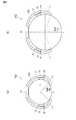
まず、図1〜図3を併せて用いて、第1実施形態に係る生体信号検出装置1を用いた血圧変動推定装置3の構成について説明する。図1は、生体信号検出装置1を用いたネックバンド型の血圧変動推定装置3の外観形状を示す平面図であり、(a)は、細い頸部に装着したときの形状を示し、(b)は、太い頸部に装着したときの形状を示す図である。また、図2は、生体信号検出装置1を用いたネックバンド型の血圧変動推定装置3の外観(装着時)を示す斜視図である。図3は、生体信号検出装置1を用いた血圧変動推定装置3の構成を示すブロック図である。(First embodiment)
First, the configuration of the blood pressure
血圧変動推定装置3は、心電信号及び脈波信号を検出し、検出した心電信号(心電波)のR波ピークと脈波信号(脈波)のピーク(立ち上がり点)との時間差から脈波伝播時間を計測し、計測した脈波伝播時間の時系列データに基づいて、使用者の血圧の変動を推定する。特に、血圧変動推定装置3は、脈波伝播時間の計測中に使用者の姿勢が変化した場合であっても、連続して、より安定的に脈波伝播時間を取得する機能を有している。また、血圧変動推定装置3は、使用者の姿勢を検知して分類し、その分類結果に基づいて脈波伝播時間を補正し、補正後の脈波伝播時間の時系列データに基づいて、血圧の変動を推定する機能を有している。 The blood pressure
そのため、血圧変動推定装置3は、主として、心電信号を検出するための一対の心電電極15,15、脈波信号を検出するための脈波センサ20、使用者の姿勢を検知するための加速度センサ22、及び、検出された心電信号と光電脈波信号から脈波伝播時間を計測・補正して血圧の変動を推定する信号処理部31を備えている(詳細は後述する)。 Therefore, the blood pressure
ここで、本実施形態では、図1,2に示されるように、血圧変動推定装置3をネックバンド型とした。血圧変動推定装置3は、例えば、図2に示されるように、使用者の頸部(首筋)に装着することにより脈波伝播時間の時系列データを取得して血圧の変動を推定するものである。血圧変動推定装置3は、使用者の頸部の後ろ側から頸部を挟むように弾性的に装着される概略U字形(或はC字形)のネックバンド13と、ネックバンド13の両端部それぞれに揺動可能に取り付けられた一対の支持部材16,16と、ネックバンド13の内側面に配設されることで使用者の頸部の両側(左右側面)に接触するセンサ部11,12と、ネックバンド13の略中央部の内側面に配設されることで使用者の頸部の後側正中線近傍に接触する光電脈波センサ20とを備えている。 Here, in this embodiment, as shown in FIGS. 1 and 2, the blood pressure
ネックバンド13は、使用者の頸部の周方向に沿って装着可能なものである。すなわち、ネックバンド13は、略U字状(或はC字形)に形成され、使用者の一方の頸部側方から他方の頸部側方まで、使用者の頸部後方に沿って装着される。より具体的には、ネックバンド13は、例えば、帯状の板バネと、この板バネの周囲を覆うゴム被覆を有して構成されている。そのため、ネックバンド13は、弾性を有し、両端部が互いに近づく方向に(すなわち、装着時には使用者の頸部を挟持する方向に)付勢されており、使用者がネックバンド13を装着した場合に、ネックバンド13が使用者の頸部に接触した状態で保持される。なお、ゴム被覆としては、生体適合性を有するものを用いることが好ましい。また、ゴム被覆に代えて例えばプラスチックからなる被覆を用いることもできる。 The
ネックバンド13は、両端部(先端側)の曲率が、中央部の曲率よりも小さく(すなわち曲率半径が大きく)なるように形成されている。そのため、ネックバンド13の中央部(すなわち、頸部の後方に接触する部分)の曲率を、頸部が細い人の頸部の曲率に合わせて設計したとしても、頸部の太い人(使用者)にも容易に装着することができる。また、ネックバンド13の両端部の曲率を小さくし、かつ、後述するように支持部材16の内側の面を凸状の曲面とすることで、支持部材16を、頸部のより後側で接触させることができる。すなわち、頸部前方、特に喉頸付近で支持部材が接触することを防止でき、使用者に違和感や不快感を与えることを抑制することができる。 The
ネックバンド13の両端部それぞれには、各端部におけるネックバンド13の短手方向(または、装着時における使用者の頸部の軸方向)を揺動軸として、一対の支持部材16,16が、揺動可能に取り付けられている。一対の支持部材16,16それぞれは、ネックバンド13の内側に向けて(すなわち、互いに近づく方向に)揺動するように付勢されている。より詳細には、支持部材16は、例えばヒンジなどによって、揺動可能に接続されている。また、ヒンジなど(接続部)には、支持部材16をネックバンド13の内側(装着時には頸部方向)に付勢する例えばバネなどの弾性部材が設けられている。なお、上記構成に代えて、例えば、可撓性(又は弾性)を有するゴムなどの素材を用いて支持部材16を形成することにより、内側への付勢力を付加する構成としてもよい。ここで、支持部材16に作用する付勢力は、ネックバンド13に作用する付勢力よりも弱く設定されている。そのため、支持部材16に作用する付勢力によって、ネックバンド13に配置されたセンサ部11,12と頸部との接触が阻害されることを防止することができる。 A pair of
また、ネックバンド13の内側、かつ支持部材16との接続部(揺動軸)付近には、各支持部材16が、所定角度以上、ネックバンド13の内側に回動する(回り込む)ことを規制する(すなわち、ネックバンド13と支持部材16との成す角が例えば100°以下にならないように規制する)規制部材(ストッパ)18が突設されている。この規制部材18により、支持部材16が内側に回動できる角度が制限され、支持部材16に対して頸部表面から垂直方向に応力が加わったときに、支持部材16が外側に揺動(回転)できなくなることが防止される。 Further, each
ここで、支持部材16は、ネックバンド13が使用者の頸部に装着された状態で平面視したときに、使用者の喉頸の中心と頸部後側の正中線とを結ぶ仮想線Lを中心として、頸部前方側±45°から±80°の範囲で頸部と接触することが好ましい。なお、ここでは、上記仮想線Lを中心として、頸部左側を「−」、頸部右側を「+」とした。より詳細に説明すると、支持部材16が接触を避けたい頸部の範囲は、頸部の前方側おおよそ±45°(合計90°)の範囲である。この範囲は胸鎖乳突筋等の厚い筋肉に覆われていないため、支持部材16が接触すると、使用者が不快に感じたり、苦しく感じたりしやすいためである。一方、支持部材16が頸部の前方側±90°(合計180°)の範囲内で頸部に接触しないと、ネックバンド13(血圧変動推定装置3)が頸部から外れやすくなってしまう。そのため、望ましくは頸部の前方側±80°(合計160°)までとなる。以上の結果、支持部材16が接触するのに適した範囲は、頸部の前方側−45°から−80°、及び+45°から+80°となる(図1(a)(b)参照)。 Here, the
支持部材16は、使用者の頸部が細くなるほど、支持部材16とネックバンド13との成す角度が小さくなる。ここで、細い頸部に装着したときの血圧変動推定装置3の外観形状を図1(a)に示す。また、太い頸部に装着したときの血圧変動推定装置3の外観形状を図1(b)に示す。図1(a)に示されるように、使用者の頸部が細い場合には、ネックバンド13が閉じ、各支持部材16とネックバンド13との成す角度が小さくなる。一方、図1(b)に示されるように、使用者の頸部が太い場合には、ネックバンド13が左右に開き、各支持部材16とネックバンド13との成す角度が大きくなる。 The
ところで、頸部を両脇(左右)から挟み込む箇所は、ネックバンド13による押圧がかかるため接触が安定するが、支持部材がないと、頸部の後ろは、頸部の太さによっては接触しない場合があり得る。このため、一対の支持部材16,16により頸部の前方から押圧をかけることにより、接触状態を安定させる。その結果、使用者の頸部(首)の太さにかかわらず、ネックバンド13を使用者の頸部後方に当接させることができ、ネックバンド13(血圧変動推定装置3)を安定して装着することができる。特に、装着時には、使用者の頸部の太さに応じてネックバンド13が閉じるとともに、支持部材16,16が内側(頸部方向)に回動するため、頸部の両脇(2か所)と、頸部の後ろとの合計3か所(3点)で頸部を安定的に保持することができる。なお、ネックバンド13にセンサ部11,12(詳細は後述する)を配置する場合には、当該センサ部11,12の位置が両脇から頸部を挟み込む箇所となる。 By the way, the place where the neck is sandwiched from both sides (left and right) is stabilized by contact with the
また、各支持部材16は、装着時に使用者の頸部と接触する内側の面が、少なくともネックバンド13の長手方向において、凸状の曲面で構成されている(すなわち、平面視した場合に円弧状に形成されている)。なお、ネックバンド13の短手方向においては必ずしも曲面になっている必要はない。また、本実施形態では、図1に示されるように、支持部材16を円弧状に形成したが、例えば、楕円状に形成してもよい(すなわち、支持部材16の外側の面は凹状でも凸状でもよい)。 Each
ネックバンド13の内側面にはセンサ部(接触部)11,12が取り付けられている。また、ネックバンド13の中央部の内側面には光電脈波センサ20が取り付けられている。さらに、支持部材16の内側面には、生体信号を検出する生体センサ(センサ部)19が取り付けられている。ここで、生体センサ19としては、例えば、心電センサ、脈波センサ(光電脈波センサ、圧電脈波センサ等)、加速度センサ、酸素飽和度センサ、音センサ(マイク)、変位センサ、温度センサ、湿度センサ等を挙げることができる。 Sensor portions (contact portions) 11 and 12 are attached to the inner side surface of the
センサ部11,12は、ネックバンド13の短手方向及び/又は長手方向を軸として揺動可能に取り付けられていることが好ましい。より具体的には、例えば、球状頭部と、該球状頭部を保持するソケットとを有して構成されるボールジョイント(図示省略)によって、センサ部11,12それぞれが、ネックバンド13の両端部に揺動回動自在に取り付けられている。 The
そのため、センサ部11,12それぞれは、ネックバンド13の短手方向を軸として揺動可能(すなわち、頸部の周方向に揺動可能)になると同時に、ネックバンド13の長手方向を軸として揺動可能(すなわち、頸部の軸方向に揺動可能)になる。なお、センサ部11,12それぞれは、ネックバンド13の短手方向及び長手方向を軸として揺動可能であればよく、頸部の径方向を軸とする回転を制限(規制)する機構を設けてもよい。なお、同様にして、生体センサ19を、ネックバンド13の短手方向及び/又は長手方向を軸として揺動可能に取り付けてもよい。 Therefore, each of the
ネックバンド13(ゴム被覆)の内部には、センサ部11,12(後述する心電電極15,15)及び光電脈波センサ20並びに加速度センサ22と信号処理部31とを電気的に接続するケーブルが配線されている。また、支持部材16,16の内部には、生体センサ19,19と信号処理部31とを電気的に接続するケーブルが配線されている。ここで、これらのケーブルは、ノイズを低減するために、同軸とすることが望ましい。 Inside the neckband 13 (rubber coating), cables for electrically connecting the
センサ部11,12は、一対の心電電極15,15を有している。心電電極15としては、例えば、銀・塩化銀、導電ゲル、導電ゴム、導電プラスチック、金属(ステンレス、Au等の腐食に強く金属アレルギーの少ないものが好ましい)、導電布、金属表面を絶縁層でコーティングした容量性結合電極等を用いることができる。ここで、導電布としては、例えば、導電性を有する導電糸からなる織物や編物、不織布が用いられる。また、導電糸としては、例えば、樹脂糸の表面をAgなどでめっきしたものや、カーボンナノチューブ・コーティングを施したもの、PEDOTなどの導電性高分子をコーティングしたものを用いることができる。また、導電性を有する導電性ポリマー糸を用いてもよい。なお、本実施形態では、心電電極15として、矩形の平面状に形成した導電布15を用いた。一対の心電電極15,15それぞれは、信号処理部31と接続されており、心電信号を信号処理部31へ出力する。 The
また、ネックバンド13の中央部には、脈波伝播時間を取得しているときの使用者(頸部)の姿勢を検出する加速度センサ22が取り付けられている。加速度センサ22は、重力加速度Gがかかる方向(すなわち鉛直方向)を検知する3軸加速度センサであり、その検出信号から、使用者が、例えば、立っているのか、寝ているのかなどを判定することができる。 Further, an
より具体的には、使用者の身体に対して、加速度センサ22がどういう位置関係にあるのかを予めキャリブレーションしておき、例えば、加速度センサ22の出力に対して、使用者が立っているときに重力加速度がかかる方向を下方向(鉛直方向)として座標変換することにより、使用者の姿勢を判定することができる。加速度センサ22も、信号処理部31と接続されており、検出信号(3軸加速度データ)を信号処理部31へ出力する。なお、加速度センサ22に代えて、例えば、ジャイロセンサ等を用いることもできる。 More specifically, the positional relationship of the
ネックバンド13の中央部の内側面(頸部と接触する面)には、加速度センサ22の近傍に、発光素子201および受光素子202を有し、光電脈波信号を検出する光電脈波センサ20が配設されている。光電脈波センサ20は、血中ヘモグロビンの吸光特性を利用して、光電脈波信号を光学的に検出するセンサである。 A photoelectric
上述したように、光電脈波センサ20は、ネックバンド13の略中央部に配設される。そのため、光電脈波センサ20は、ネックバンド13が使用者の頸部に装着されたときに(すなわち、脈波伝播時間が取得される際に)、使用者の頸部後側の正中線(又はその近傍)において頸部と接触する位置に配置される。なお、光電脈波センサ20は、表面が、ネックバンド13の表面と同一(又は略同一)となるように形成されている。 As described above, the photoelectric
光電脈波センサ20及び加速度センサ22は、互いに近接して配設されており、使用時(計測時)には、使用者の頸部(首)に装着されることとなる。このように、光電脈波センサ20と姿勢を判定するための加速度センサ22とを同じ部位に装着することで、姿勢判定と脈波伝播時間の相関を高めることができる。また、手足等ではなく頸部に装着することで、手足の血管内血圧ではなく、脳卒中や心筋梗塞等のリスクと相関が高いと推測される頸部の血管内血圧の推定ができる。さらに、複数のセンサを別々の部位に装着するのではなく頸部に集約することで装着の煩雑さを低減でき、また日常行動への制約を小さくすることもできる。なお、加速度センサ22は、光電脈波センサ20の近傍に配置することが望ましいが、光電脈波センサ20との相対位置が変動しない構造であれば、装置内の他の箇所に配置してもよい。 The photoelectric
発光素子201は、後述する信号処理部31の駆動部350から出力されるパルス状の駆動信号に応じて発光する。発光素子201としては、例えば、LED、VCSEL(Vertical Cavity Surface Emitting LASER)、又は共振器型LED等を用いることができる。なお、駆動部350は、発光素子201を駆動するパルス状の駆動信号を生成して出力する。 The
受光素子202は、発光素子201から照射され、頸部を透過して、又は頸部に反射して入射される光の強さに応じた検出信号を出力する。受光素子202としては、例えば、フォトダイオードやフォトトランジスタ等が好適に用いられる。本実施形態では、受光素子202として、フォトダイオードを用いた。 The
受光素子202は、信号処理部31に接続されており、受光素子202で得られた検出信号(光電脈波信号)は信号処理部31に出力される。 The
また、センサ部11の内部には、光電脈波センサ20や、信号処理部31、無線通信モジュール60などに電力を供給するバッテリ(図示省略)が収納されている。センサ部12の内部には、信号処理部31、及び、血圧変動や、計測した脈波伝播時間、心電信号、光電脈波信号などの生体情報を外部の機器に送信する無線通信モジュール60が収納されている。 In addition, a battery (not shown) that supplies electric power to the photoelectric
上述したように、一対の心電電極15,15、及び光電脈波センサ20それぞれは、信号処理部31に接続されており、検出された心電信号及び光電脈波信号が信号処理部31に入力される。また、加速度センサ22も、信号処理部31に接続されており、検出された3軸加速度信号が信号処理部31に入力される。 As described above, each of the pair of
信号処理部31は、入力された心電信号を処理して、心拍数や心拍間隔などを計測する。また、信号処理部31は、入力された光電脈波信号を処理して、脈拍数や脈拍間隔などを計測する。さらに、信号処理部31は、検出した心電信号(心電波)のR波ピークと光電脈波信号(もしくは加速度脈波信号)のピーク(立ち上がり点)との時間差から脈波伝播時間等を計測する。そして、信号処理部31は、計測した脈波伝播時間の時系列データ(変動)から使用者の血圧の変動を推定する。 The
そのため、信号処理部31は、心電信号増幅部311、脈波信号増幅部321、第1信号処理部310、第2信号処理部320、ピーク検出部316,326、ピーク補正部318,328、脈波伝播時間計測部330、姿勢分類部340、脈波伝播時間変動取得部341、及び血圧変動推定部342を有している。また、上記第1信号処理部310は、アナログフィルタ312、A/Dコンバータ313、ディジタルフィルタ314を有している。一方、第2信号処理部320は、アナログフィルタ322、A/Dコンバータ323、ディジタルフィルタ324、2階微分処理部325を有している。 Therefore, the
ここで、上述した各部の内、ディジタルフィルタ314,324、2階微分処理部325、ピーク検出部316,326、ピーク補正部318,328、脈波伝播時間計測部330、姿勢分類部340、脈波伝播時間変動取得部341、及び血圧変動推定部342は、演算処理を行うCPU、該CPUに各処理を実行させるためのプログラムやデータを記憶するROM、及び演算結果などの各種データを一時的に記憶するRAM等により構成されている。すなわち、ROMに記憶されているプログラムがCPUによって実行されることにより、上記各部の機能が実現される。 Here, among the above-described units, the
心電信号増幅部311は、例えばオペアンプ等を用いた増幅器により構成され、一対の心電電極(導電布)15,15により検出された心電信号を増幅する。心電信号増幅部311で増幅された心電信号は、第1信号処理部310に出力される。同様に、脈波信号増幅部321は、例えばオペアンプ等を用いた増幅器により構成され、光電脈波センサ20により検出された光電脈波信号を増幅する。脈波信号増幅部321で増幅された光電脈波信号は、第2信号処理部320に出力される。 The electrocardiogram
第1信号処理部310は、上述したように、アナログフィルタ312、A/Dコンバータ313、ディジタルフィルタ314を有しており、心電信号増幅部311で増幅された心電信号に対して、フィルタリング処理を施すことにより拍動成分を抽出する。 As described above, the first
また、第2信号処理部320は、上述したように、アナログフィルタ322、A/Dコンバータ323、ディジタルフィルタ324、2階微分処理部325を有しており、脈波信号増幅部321で増幅された光電脈波信号に対して、フィルタリング処理及び2階微分処理を施すことにより拍動成分を抽出する。 Further, as described above, the second
アナログフィルタ312,322、及び、ディジタルフィルタ314,324は、心電信号、光電脈波信号を特徴づける周波数以外の成分(ノイズ)を除去し、S/Nを向上するためのフィルタリングを行う。より詳細には、心電信号は一般的に0.1から200Hzの周波数成分、光電脈波信号は0.1から数十Hz付近の周波数成分が支配的であるため、ローパスフィルタやバンドパスフィルタ等のアナログフィルタ312,322、及びディジタルフィルタ314,324を用いてフィルタリング処理を施し、上記周波数範囲の信号のみを選択的に通過させることによりS/Nを向上する。 The analog filters 312, 322 and the
なお、拍動成分の抽出のみを目的とする場合には、ノイズ耐性を向上するために通過周波数範囲をより狭くして拍動成分以外の成分を遮断してもよい。また、アナログフィルタ312,322とディジタルフィルタ314,324は必ずしも両方備える必要はなく、アナログフィルタ312,322とディジタルフィルタ314,324のいずれか一方のみを設ける構成としてもよい。なお、アナログフィルタ312、ディジタルフィルタ314によりフィルタリング処理が施された心電信号は、ピーク検出部316へ出力される。同様に、アナログフィルタ322、ディジタルフィルタ324によりフィルタリング処理が施された光電脈波信号は、2階微分処理部325へ出力される。 In the case where only the extraction of the pulsating component is intended, in order to improve noise resistance, the pass frequency range may be narrowed to block components other than the pulsating component. The analog filters 312, 322 and the
2階微分処理部325は、光電脈波信号を2階微分することにより、2階微分脈波(加速度脈波)信号を取得する。取得された加速度脈波信号は、ピーク検出部326へ出力される。なお、光電脈波のピーク(立ち上がり点)は変化が明確でなく検出しにくいことがあるため、加速度脈波に変換してピーク検出を行うことが好ましいが、2階微分処理部325を設けることは必須ではなく、省略した構成としてもよい。 The second-order
ピーク検出部316は、第1信号処理部310により信号処理が施された(拍動成分が抽出された)心電信号のピーク(R波)を検出する。一方、ピーク検出部326は、第2信号処理部320によりフィルタリング処理が施された光電脈波信号(加速度脈波)のピークを検出する。なお、ピーク検出部316、及びピーク検出部326それぞれは、心拍間隔、及び脈拍間隔の正常範囲内においてピーク検出を行い、検出したすべてのピークについて、ピーク時間、ピーク振幅等の情報をRAM等に保存する。 The
ピーク補正部318は、第1信号処理部310(アナログフィルタ312、A/Dコンバータ313、ディジタルフィルタ314)における心電信号の遅延時間を求める。ピーク補正部318は、求めた心電信号の遅延時間に基づいて、ピーク検出部316により検出された心電信号のピークを補正する。同様に、ピーク補正部328は、第2信号処理部320(アナログフィルタ322、A/Dコンバータ323、ディジタルフィルタ324、2階微分処理部325)における光電脈波信号の遅延時間を求める。ピーク補正部328は、求めた光電脈波信号の遅延時間に基づいて、ピーク検出部326により検出された光電脈波信号(加速度脈波信号)のピークを補正する。補正後の心電信号のピーク、及び補正後の光電脈波信号(加速度脈波)のピークは、脈波伝播時間計測部330に出力される。なお、ピーク補正部318を設けることは必須ではなく、省略した構成としてもよい。 The
脈波伝播時間計測部330は、ピーク補正部318により補正された心電信号のR波ピークと、ピーク補正部328により補正された光電脈波信号(加速度脈波)のピークとの間隔(時間差)から脈波伝播時間を時系列的に取得する。 The pulse wave propagation
脈波伝播時間計測部330は、脈波伝播時間に加えて、例えば、心電信号から心拍数、心拍間隔、心拍間隔変化率等も算出する。同様に、脈波伝播時間計測部330は、光電脈波信号(加速度脈波)から脈拍数、脈拍間隔、脈拍間隔変化率等も算出する。なお、取得された脈波伝播時間の時系列データは、姿勢分類部340に出力される。 In addition to the pulse wave propagation time, the pulse wave propagation
姿勢分類部340は、加速度センサ22の検出信号(3軸加速度データ)に基づいて使用者の姿勢を判定(推定)するとともに、判定した姿勢に応じて、脈波伝播時間の時系列データを姿勢毎に分類する。例えば、姿勢分類部340は、脈波伝播時間の時系列データを、立位、倒立位、仰臥位、左側臥位、右側臥位、及び伏臥位を含む姿勢毎に分類する。なお、姿勢分類部340による脈波伝播時間の分類結果(分類された脈波伝播時間の時系列データ)は脈波伝播時間変動取得部341に出力される。 The
脈波伝播時間変動取得部341は、姿勢分類部340により姿勢毎に分類された脈波伝播時間の時系列データに基づいて、脈波伝搬時間の変動を求める。 The pulse wave propagation time
より具体的には、脈波伝播時間変動取得部341は、まず、分類された姿勢の中から基準とする姿勢を設定し、該基準姿勢に合わせて、該基準姿勢と異なる姿勢に分類された脈波伝播時間の時系列データを補正する。そして、脈波伝播時間変動取得部341は、基準姿勢における脈波伝播時間の時系列データ、及び、補正された(補正後の)脈波伝播時間の時系列データに基づいて、脈波伝搬時間の変動を求める。 More specifically, the pulse wave transit time
その際に、脈波伝播時間変動取得部341は、取得された脈波伝搬時間の時系列データの時間が最も長い姿勢を基準姿勢として設定する。そして、脈波伝播時間変動取得部341は、姿勢毎の脈波伝播時間の時系列データを曲線で近似したときの近似曲線の相関係数が大きくなるように(好ましくは最大となるように)、姿勢毎の脈波伝播時間の時系列データを補正し、補正後の時系列データから脈波伝播時間の変動を求める。このように、近似曲線の相関係数が大きくなるように、姿勢毎の脈波伝播時間を補正し、補正後の時系列データから脈波伝播時間の変動傾向を推定することで、姿勢変化がある場合でも長時間の脈波伝播時間変動傾向(血圧変動傾向)を煩雑な較正なしに推定できる。なお、上記近似曲線の求め方としては、例えば、最小二乗法を用いることができる。 At that time, the pulse wave propagation time
なお、上述した方法に代えて、各姿勢毎の脈波伝播時間をそれぞれ時系列に並べ、それぞれについて近似曲線を求めてもよい。この場合、複数の近似曲線が算出されるが、所定の時間割合以上の姿勢の近似曲線のうち、その相関係数が大きい近似曲線を選択する。脈波伝播時間変動取得部341により取得された脈波伝播時間の変動データは、血圧変動推定部342に出力される。 Instead of the method described above, the pulse wave propagation times for each posture may be arranged in time series, and approximate curves may be obtained for each. In this case, although a plurality of approximate curves are calculated, an approximate curve having a large correlation coefficient is selected from the approximate curves having a posture of a predetermined time ratio or more. The fluctuation data of the pulse wave propagation time acquired by the pulse wave propagation time
血圧変動推定部342は、補正後の脈波伝播時間の変動データ、及び予め定められている脈波伝播時間と血圧との関係(相関式)に基づいて、血圧変動を推定する。ここで、血圧変動推定部342は、例えば、予め求めておいた基準姿勢での脈波伝播時間と血圧との相関式から血圧変動を推定することで、補正後の脈波伝播時間変動から血圧変動を推定することができる。 The blood pressure
なお、血圧変動推定部342は、事前に、装着状態で姿勢判定のためのキャリブレーション、すなわち、加速度センサ22の出力信号(鉛直方向)と、使用者の姿勢との関係のキャリブレーションを行うとともに、基準とする姿勢からの角度のずれ(ずれ角度)と、心臓から脈波測定部位(すなわち光電脈波センサ20の装着部位)までの高さとの関係式を求めてRAM等のメモリに記憶し、脈波伝播時間の計測時(使用時)に、事前に行ったキャリブレーションの結果に基づいて、加速度センサ22により検知された使用者の姿勢と、基準となる姿勢との角度のずれ(ずれ角度)を算出し、脈波伝播時間から血圧値を演算する際に、算出された角度のずれ(ずれ角度)と、予め記憶されている上記関係式とに基づいて、心臓から脈波測定部位(光電脈波センサ20の装着部位)までの高さを求め、当該高さに応じて血圧値を補正してもよい。ただし、血圧値は必ずしも求めなくてもよい。 The blood pressure
推定された血圧変動、血圧値をはじめ、算出された脈波伝播時間、心拍数、心拍間隔、脈拍数、脈拍間隔、光電脈波、加速度脈波、3軸加速度等の計測データは、RAM等のメモリや無線通信モジュール60等に出力される。ここで、これらの計測データは、メモリに保持しておき、日々の変動履歴と共に読み出せるようにしておいてもよいし、パーソナルコンピュータ(PC)やスマートフォン等の外部機器にリアルタイムに無線で送信するようにしてもよい。また、測定中は装置内のメモリに保存しておき、測定終了後に自動的に外部機器に接続してデータを送信する構成としてもよい。 Measurement data such as estimated blood pressure fluctuation, blood pressure value, calculated pulse wave propagation time, heart rate, heart rate interval, pulse rate, pulse interval, photoelectric pulse wave, acceleration pulse wave, triaxial acceleration, etc. are stored in RAM, etc. To the memory, the
次に、図4を参照しつつ、血圧変動推定装置3の動作について説明する。図4は、血圧変動推定装置3による血圧変動推定処理の処理手順を示すフローチャートである。図4に示される処理は、主として信号処理部31によって所定のタイミングで繰り返して実行される。 Next, the operation of the blood pressure
血圧変動推定装置3(ネックバンド13)が頸部に装着され、センサ部11,12(心電電極15,15)が頸部の左右に接触するとともに、光電脈波センサ20が頸部の後側正中線(又はその近傍)に接触すると、ステップS100では、一対の心電電極15,15により検出された心電信号、及び光電脈波センサ20により検出された光電脈波信号が読み込まれる。続くステップS102では、ステップS100で読み込まれた心電信号、及び光電脈波信号に対してフィルタリング処理が施される。また、光電脈波信号が2階微分されることにより加速度脈波が取得される。 The blood pressure fluctuation estimation device 3 (neckband 13) is attached to the neck, the
続いて、ステップS104では、例えば、光電脈波センサ20の受光量に基づいて、脈波伝播時間計測装置1の装着状態の判定が行われる。すなわち、光電脈波センサ20では、発光素子201から照射され、生体を透過して/生体で反射されて戻ってきた光を受光素子202で受けて、その光量の変動を光電脈波信号として検出するため、装置が適切に装着されていない状態では信号光の受光量が減少する。そこで、ステップS104では、受光量が所定値以上であるか否かについての判断が行われる。ここで、受光量が所定値以上である場合には、ステップS108に処理が移行する。一方、受光量が所定値未満のときには、装着エラーと判定され、ステップS106において、装着エラー情報(ワーニング情報)が出力される。その後、本処理から一旦抜ける。なお、上述した光電脈波センサ20の受光量を用いる方法に代えて、例えば、光電脈波信号の振幅、心電波形のベースラインの安定度やノイズ周波数成分比率を用いる方法等を採用することもできる。 Subsequently, in step S104, for example, the mounting state of the pulse wave transit
ステップS108では、加速度センサ22により検出された頸部の加速度が所定のしきい値以上であるか否か(すなわち、頸部が動き、体動ノイズが大きくなるか否か)についての判断が行われる。ここで、頸部の加速度が所定のしきい値未満の場合には、ステップS112に処理が移行する。一方、頸部の加速度が所定のしきい値以上のときには、ステップS110において、体動エラー情報が出力された後、本処理から一旦抜ける。 In step S108, a determination is made as to whether or not the neck acceleration detected by the
ステップS112では、3軸加速度データに基づいて、使用者(測定部位)の姿勢が判定される。続くステップS114では、心電信号、光電脈波信号(加速度脈波信号)のピークが検出される。そして、検出された心電信号のR波ピークと、光電脈波信号(加速度脈波)のピークとの時間差(ピーク時間差)が算出される。 In step S112, the posture of the user (measurement site) is determined based on the triaxial acceleration data. In the subsequent step S114, the peaks of the electrocardiogram signal and the photoelectric pulse wave signal (acceleration pulse wave signal) are detected. Then, the time difference (peak time difference) between the R wave peak of the detected electrocardiogram signal and the peak of the photoelectric pulse wave signal (acceleration pulse wave) is calculated.
次に、ステップS116では、心電信号のR波ピーク及び光電脈波信号(加速度脈波)のピークそれぞれの遅延時間(ずれ量)が求められるとともに、求められた遅延時間に基づいて、心電信号のR波ピークと光電脈波信号(加速度脈波)のピークとの時間差(ピーク時間差)が補正される。 Next, in step S116, the delay time (shift amount) of each of the R wave peak of the electrocardiogram signal and the peak of the photoelectric pulse wave signal (acceleration pulse wave) is obtained, and based on the obtained delay time, the electrocardiogram is obtained. The time difference (peak time difference) between the R wave peak of the signal and the peak of the photoelectric pulse wave signal (acceleration pulse wave) is corrected.
続いて、ステップS118では、ステップS116で補正されたピーク時間差が所定時間(例えば0.01sec.)以上か否かについての判断が行われる。ここで、ピーク時間差が所定時間以上の場合には、ステップS122に処理が移行する。一方、ピーク時間差が所定未満のときには、ステップS120においてエラー情報(ノイズ判定)が出力された後、本処理から一旦抜ける。 Subsequently, in step S118, a determination is made as to whether or not the peak time difference corrected in step S116 is greater than or equal to a predetermined time (for example, 0.01 sec.). If the peak time difference is greater than or equal to the predetermined time, the process proceeds to step S122. On the other hand, when the peak time difference is less than the predetermined value, error information (noise determination) is output in step S120, and then the process is temporarily exited.
ステップS122では、ステップS114で算出されたピーク時間差が脈波伝播時間として確定されるとともに、脈波間隔が取得される。 In step S122, the peak time difference calculated in step S114 is determined as the pulse wave propagation time, and the pulse wave interval is acquired.
続いて、ステップS124では、使用者の姿勢毎に脈波伝播時間が分類される。なお、脈波伝播時間の分類方法については上述したとおりであるので、ここでは詳細な説明を省略する。 Subsequently, in step S124, the pulse wave propagation time is classified for each posture of the user. Since the pulse wave propagation time classification method is as described above, detailed description is omitted here.
次に、ステップS126では、近似曲線の相関係数が最も大きくなるように、脈波伝播時間が補正される。なお、脈波伝播時間の補正方法については上述したとおりであるので、ここでは詳細な説明を省略する。 Next, in step S126, the pulse wave propagation time is corrected so that the correlation coefficient of the approximate curve becomes the largest. Since the pulse wave propagation time correction method is as described above, detailed description thereof is omitted here.
続いて、ステップS128において、補正後の脈波伝播時間の変動から血圧変動が推定される。なお、血圧変動の推定方法については上述したとおりであるので、ここでは詳細な説明を省略する。そして、ステップS130において、取得された血圧変動データ等が、例えば、メモリや、スマートフォン等の外部機器に出力される。その後、本処理から一旦抜ける。 Subsequently, in step S128, the blood pressure fluctuation is estimated from the fluctuation of the corrected pulse wave propagation time. Since the blood pressure fluctuation estimation method is as described above, detailed description thereof is omitted here. In step S130, the acquired blood pressure fluctuation data or the like is output to an external device such as a memory or a smartphone. Thereafter, the process is temporarily exited.
以上、詳細に説明したように、本実施形態によれば、ネックバンド13が、略U字状に形成され、両端部が互いに近づく方向(すなわち、装着時に使用者の頸部を挟持する方向)に付勢され、かつ、一対の支持部材16,16それぞれが、ネックバンド13の内側に向けて(すなわち、装着時に使用者の頸部を挟持する方向に)揺動するように付勢されている。そのため、使用者の頸部の太さに応じて、ネックバンド13の内径、及び支持部材16,16の揺動角が自動的(自律的)に調節される。ここで、支持部材16,16が揺動して頸部に当接することによって、頸部に対してネックバンド13を頸部前方へ押し出すように押力が作用し、ネックバンド13の中央部と頸部後方とが確実に接触することにより、頸部後方及び頸部左右側の3か所で接触し、安定的な装着状態が保持される。その結果、ネックバンド13の長さを調節する機構を備えることなく、使用者の頸部の太さにかかわらず、使用者の頸部により安定的に装着する(すなわち、センサ部11,12及び光電脈波センサ20等と頸部との接触状態を良好に保つ)ことが可能となる。 As described above in detail, according to the present embodiment, the
本実施形態によれば、支持部材16が、装着時に使用者の頸部と接触する内側の面が、ネックバンド13の長手方向において、凸状の曲面で構成されている。そのため、頸部のより後側で支持部材16を接触させることができる。すなわち、頸部前方、特に喉頸付近で支持部材16が接触することを防止できるため、使用者に違和感や不快感を与えることを抑制することが可能となる。また、支持部材16の内側(頸部側)の面が角のない凸状の曲面とされていることから、頸部の太さにかかわらず、より接触面積を大きくすることができ、安定して接触させることができる。 According to the present embodiment, the inner surface of the
本実施形態によれば、ネックバンド13の両先端部の曲率が、中央部の曲率よりも小さく(すなわち曲率半径が大きく)なるように形成されている。そのため、ネックバンド13の中央部(すなわち、頸部の後方に接触する部分)の曲率を、頸部が細い人の頸部の曲率に合わせて設計したとしても、頸部の太い人(使用者)にも容易に装着することができる。また、ネックバンド13の両先端部の曲率を小さくし、かつ、上述したように支持部材16の内側の面を凸状の曲面とすることで、支持部材16を、頸部のより後側で接触させることができる。すなわち、頸部前方、特に喉頸付近で支持部材16が接触することを防止でき、使用者に違和感や不快感を与えることを抑制することが可能となる。 According to this embodiment, the curvature of the both front-end | tip parts of the
本実施形態によれば、各支持部材16が、所定角度以上、ネックバンド13の内側に揺動する(回り込む)ことを規制する規制部材18をさらに備えているため、支持部材16が外側に揺動(回転)できなくなることを防止することが可能となる。 According to the present embodiment, since each
本実施形態によれば、支持部材16に作用する付勢力が、ネックバンド13に作用する付勢力よりも弱く設定されているため、支持部材16に作用する付勢力によって、ネックバンド13に配置されたセンサ部11,12と頸部との接触が阻害されることを防止することが可能となる。 According to the present embodiment, since the urging force acting on the
本実施形態によれば、支持部材16の内側面に取り付けられ、生体信号を検出する生体センサ19をさらに備えている。そのため、使用者の頸部の太さにかかわらず、生体センサ19を頸部に安定して密着させることができるため、生体信号を安定して測定することが可能となる。 According to this embodiment, the biosensor 19 which is attached to the inner surface of the
本実施形態によれば、支持部材16が、ネックバンド13が使用者の頸部に装着された状態で平面視したときに、使用者の喉頸の中心と頸部後側の正中線とを通る仮想線Lを中心として、頸部前方側±45°から±80°の範囲内で頸部と接触するため、頸部前方、特に喉頸付近に支持部材16が接触することがなく、使用者に違和感や不快感を与えることを抑制することが可能となる。 According to this embodiment, when the
(第2実施形態)
次に、図5を用いて、第2実施形態に係る生体信号検出装置2を用いた血圧変動推定装置4について説明する。ここでは、上述した第1実施形態と同一・同様な構成については説明を簡略化又は省略し、異なる点を主に説明する。図5は、生体信号検出装置2を用いたネックバンド型の血圧変動推定装置4の外観形状を示す平面図であり、(a)は、細い頸部に装着したときの形状を示し、(b)は、太い頸部に装着したときの形状を示す図である。なお、図5において第1実施形態と同一又は同等の構成要素については同一の符号が付されている。(Second Embodiment)
Next, the blood pressure
血圧変動推定装置4(生体信号検出装置2)は、ネックバンド13に代えてネックバンド13Bを備えるとともに、一対の支持部材16,16に代えて、一対の支持部材17,17を備えている点で、上述した第1実施形態に係る血圧変動推定装置3(生体信号検出装置1)と異なっている。なお、その他の構成は、上述した血圧変動推定装置4(生体信号検出装置1)と同一又は同様であるので、ここでは詳細な説明を省略する。 The blood pressure fluctuation estimation device 4 (biological signal detection device 2) includes a
図5に示されるように、ネックバンド13Bは、両端部と中央部とで曲率が一定である点で、上述したネックバンド13(両端部の曲率が中央部の曲率よりも小さい)と異なっている。 As shown in FIG. 5, the
また、図5に示されるように、支持部材17は、内側(頸部側)の頸部と接触する面がネックバンド13の長手方向において凹状の曲面となっている点で、上述した支持部材16(凸状の曲面となっている)と異なっている。そのため、図5(a)に示されるように、使用者の頸部が細い場合、支持部材17と頸部との接触位置が、上述した第1実施形態(図1(a)参照)のときよりも頸部前側(喉頸寄り)となる。なお、その他の構成は、上述した血圧変動推定装置3(生体信号検出装置1)と同一又は同様であるので、ここでは詳細な説明を省略する。 Further, as shown in FIG. 5, the
血圧変動推定装置4(生体信号検出装置2)は、上述した血圧変動推定装置3(生体信号検出装置1)と同様の方法で使用することができる。すなわち、使用者は、血圧変動推定装置4(生体信号検出装置2)を頸部に装着するだけで、心電信号、光電脈波信号、脈波伝搬時間、及び血圧変動などを検出・計測することができる。なお、血圧変動推定装置3(生体信号検出装置1)の使用方法は、上述したとおりであるので、ここでは詳細な説明を省略する。 The blood pressure fluctuation estimation device 4 (biological signal detection device 2) can be used in the same manner as the blood pressure fluctuation estimation device 3 (biological signal detection device 1) described above. That is, the user detects and measures an electrocardiogram signal, a photoelectric pulse wave signal, a pulse wave propagation time, a blood pressure fluctuation, and the like only by wearing the blood pressure fluctuation estimation device 4 (biological signal detection device 2) on the neck. be able to. In addition, since the usage method of the blood pressure fluctuation estimation apparatus 3 (biological signal detection apparatus 1) is as above-mentioned, detailed description is abbreviate | omitted here.
本実施形態によれば、上述した第1実施形態に係る血圧変動推定装置3(生体信号検出装置1)と同様に、ネックバンドの長さを調節する機構を備えることなく、使用者の頸部の太さにかかわらず、使用者の頸部により安定的に装着する(すなわち、センサ部11,12や光電脈波センサ20等と頸部との接触状態を良好に保つ)ことが可能となる。 According to this embodiment, similarly to the blood pressure fluctuation estimation device 3 (biological signal detection device 1) according to the first embodiment described above, the user's neck is not provided with a mechanism for adjusting the length of the neckband. Regardless of the thickness of the user, it is possible to wear it more stably on the neck of the user (that is, keep the contact between the
以上、本発明の実施の形態について詳細に説明したが、本発明は、上記実施形態に限定されるものではなく種々の変形が可能である。例えば、上記実施形態では、生体信号検出装置1(2)を血圧変動推定装置3(4)に適用した場合を例にして説明したが、生体信号検出装置1(2)は血圧変動推定装置3(4)以外にも適用することができる。 As mentioned above, although embodiment of this invention was described in detail, this invention is not limited to the said embodiment, A various deformation | transformation is possible. For example, in the above embodiment, the case where the biological signal detection device 1 (2) is applied to the blood pressure fluctuation estimation device 3 (4) has been described as an example, but the biological signal detection device 1 (2) is a blood pressure
上記実施形態では、生体信号検出装置1(2)が、光電脈波センサ20を備えていたが、光電脈波センサ20を備えていない構成としてもよい。また、脈波センサとして、光電脈波センサに代えて、例えば圧電脈波センサなどを用いてもよい。さらに、上記実施形態では、各支持部材16(17)に一つの生体センサ19が配設されていたが、複数の生体センサを配設してもよい。逆に、生体センサ19を備えない構成としてもよい。なお、上述した各種センサに加えて、例えば、酸素飽和度センサ、音センサ(マイク)、変位センサ、温度センサ、湿度センサなどの生体センサを用いる構成としてもよい。さらに、センサ部11,12は、一対の心電電極15,15を有しているとしたが、光電脈波センサ、圧電脈波センサ、酸素飽和度センサ、音センサ(マイク)、変位センサ、温度センサ、湿度センサなどの生体センサを配設してもよい。 In the above embodiment, the biological signal detection device 1 (2) includes the photoelectric
上記実施形態では、姿勢判定や、姿勢毎の脈波伝播時間の補正、血圧変動の推定等の処理を信号処理部31で行ったが、取得した心電信号、光電脈波信号、3軸加速度等のデータを例えばパーソナルコンピュータ(PC)やスマートフォン等に無線で出力し、PCやスマートフォン側で、上記姿勢判定や、姿勢毎の脈波伝播時間の補正、血圧変動の推定等の処理を行う構成としてもよい。このような場合、上述した相関式等のデータは、PCやスマートフォン側に記憶される。 In the above-described embodiment, processing such as posture determination, correction of pulse wave propagation time for each posture, estimation of blood pressure fluctuation, etc. was performed by the
1,2 生体信号検出装置
3,4 血圧変動推定装置
11,12 センサ部
13,13B ネックバンド
15 心電電極
16,17 支持部材
18 規制部材
19 生体センサ
20 光電脈波センサ
201 発光素子
202 受光素子
22 加速度センサ
31 信号処理部
310 第1信号処理部
320 第2信号処理部
311 心電信号増幅部
321 脈波信号増幅部
312,322 アナログフィルタ
313,323 A/Dコンバータ
314,324 ディジタルフィルタ
325 2階微分処理部
316,326 ピーク検出部
318,328 ピーク補正部
330 脈波伝播時間計測部
340 姿勢分類部
341 脈波伝播時間変動取得部
342 血圧変動推定部
60 無線通信モジュール
DESCRIPTION OF
Claims (9)
Translated fromJapanese前記ネックバンドの内側面に取り付けられ、生体信号を検出するセンサ部と、
前記ネックバンドの両端部それぞれに、装着時における使用者の頸部の軸方向を揺動軸として、揺動可能に取り付けられた一対の支持部材と、を備え、
前記ネックバンドは、略U字状に形成され、両端部が互いに近づく方向に付勢され、
前記一対の支持部材それぞれは、前記ネックバンドの内側に向けて揺動するように付勢されていることを特徴とする生体信号検出装置。A neckband that can be worn along the circumferential direction of the user's neck;
A sensor unit that is attached to the inner surface of the neckband and detects a biological signal;
A pair of support members attached to each end of the neckband so as to be swingable with the axial direction of the neck of the user when worn as a swing axis;
The neckband is formed in a substantially U shape, and is biased in a direction in which both ends approach each other,
Each of the pair of support members is urged so as to swing toward the inside of the neckband.
前記ネックバンドの内側面に取り付けられ、生体信号を検出するセンサ部と、
前記ネックバンドの両端部それぞれに、各端部におけるネックバンドの短手方向を揺動軸として、揺動可能に取り付けられた一対の支持部材と、を備え、
前記ネックバンドは、略U字状に形成され、両端部が互いに近づく方向に付勢され、
前記一対の支持部材それぞれは、前記ネックバンドの内側に向けて揺動するように付勢されていることを特徴とする生体信号検出装置。A neckband that can be worn along the circumferential direction of the user's neck;
A sensor unit that is attached to the inner surface of the neckband and detects a biological signal;
A pair of support members attached to each end of the neckband so as to be swingable with the short direction of the neckband at each end as a swing axis, and
The neckband is formed in a substantially U shape, and is biased in a direction in which both ends approach each other,
Each of the pair of support members is urged so as to swing toward the inside of the neckband.
The support member has a neck line around the imaginary line connecting the center of the user's throat and the midline of the back of the neck when viewed in plan with the neckband attached to the user's neck. The biological signal detection device according to claim 1, wherein the living body signal detection device is in contact with the neck in a range of ± 45 ° to ± 80 ° on the front side of the head.
Priority Applications (1)
| Application Number | Priority Date | Filing Date | Title |
|---|---|---|---|
| JP2015242887AJP6569509B2 (en) | 2015-12-14 | 2015-12-14 | Biological signal detection device |
Applications Claiming Priority (1)
| Application Number | Priority Date | Filing Date | Title |
|---|---|---|---|
| JP2015242887AJP6569509B2 (en) | 2015-12-14 | 2015-12-14 | Biological signal detection device |
Publications (2)
| Publication Number | Publication Date |
|---|---|
| JP2017108761A JP2017108761A (en) | 2017-06-22 |
| JP6569509B2true JP6569509B2 (en) | 2019-09-04 |
Family
ID=59078919
Family Applications (1)
| Application Number | Title | Priority Date | Filing Date |
|---|---|---|---|
| JP2015242887AActiveJP6569509B2 (en) | 2015-12-14 | 2015-12-14 | Biological signal detection device |
Country Status (1)
| Country | Link |
|---|---|
| JP (1) | JP6569509B2 (en) |
Families Citing this family (7)
| Publication number | Priority date | Publication date | Assignee | Title |
|---|---|---|---|---|
| WO2019130832A1 (en)* | 2017-12-27 | 2019-07-04 | アルプスアルパイン株式会社 | Biological information measurement electrode and method for manufacturing biological information measurement electrode |
| JP2019217233A (en)* | 2018-06-20 | 2019-12-26 | 株式会社モノプロダイム | Sleep evaluation device and sleep control method using the same |
| WO2021103758A1 (en)* | 2019-11-29 | 2021-06-03 | 未来穿戴技术有限公司 | Neck massager |
| WO2021181735A1 (en)* | 2020-03-09 | 2021-09-16 | 株式会社村田製作所 | Bioacoustic sensor and stethoscope equipped therewith |
| WO2022011327A1 (en)* | 2020-07-10 | 2022-01-13 | Secondwave Systems, Inc. | Systems and methods for targeting an organ with ultrasound stimulation for treating inflammation |
| CN116157069A (en)* | 2020-08-27 | 2023-05-23 | 株式会社岛津制作所 | Wearable equipment and detecting system |
| CN112842392B (en)* | 2021-02-04 | 2023-06-20 | 广东诗奇制造有限公司 | Wearable blood pressure detection device |
Family Cites Families (6)
| Publication number | Priority date | Publication date | Assignee | Title |
|---|---|---|---|---|
| JP2000166886A (en)* | 1998-12-02 | 2000-06-20 | Nippon Colin Co Ltd | Carotid pulse wave detecting device |
| JP2006026394A (en)* | 2004-06-15 | 2006-02-02 | Sysmex Corp | Noninvasive organism measuring apparatus |
| JP2007202939A (en)* | 2006-02-06 | 2007-08-16 | Masafumi Matsumura | Biological information detecting apparatus |
| JP5055502B2 (en)* | 2008-03-10 | 2012-10-24 | 日立コンシューマエレクトロニクス株式会社 | Biopsy device |
| KR200454882Y1 (en)* | 2009-07-21 | 2011-08-03 | 주식회사 바이오스페이스 | Electrode device |
| JP6210154B2 (en)* | 2014-04-28 | 2017-10-11 | 株式会社村田製作所 | Biological signal detection device |
- 2015
- 2015-12-14JPJP2015242887Apatent/JP6569509B2/enactiveActive
Also Published As
| Publication number | Publication date |
|---|---|
| JP2017108761A (en) | 2017-06-22 |
Similar Documents
| Publication | Publication Date | Title |
|---|---|---|
| JP6569509B2 (en) | Biological signal detection device | |
| JP6597790B2 (en) | Pulse wave propagation time measurement device and biological state estimation device | |
| JP6583427B2 (en) | Pulse wave propagation time measurement device and biological state estimation device | |
| JP6729704B2 (en) | Blood pressure estimation device | |
| JP6662459B2 (en) | Blood pressure measurement device | |
| US20220031243A1 (en) | Biological signal detection apparatus | |
| CN106231995B (en) | Pulse wave propagation time measuring device and living body state estimating device | |
| EP2116183B1 (en) | Robust opto-electrical ear located cardiovascular monitoring device | |
| EP2786702B1 (en) | Physiology signal sensing device | |
| JP6620821B2 (en) | Fatigue detection device | |
| EP3094235B1 (en) | Biosensing electrodes | |
| US20160199001A1 (en) | Heart rate detection earphone | |
| CN106473718B (en) | Neckstrap type biological information detection device | |
| CN111166305A (en) | Ear physiological signal acquisition device | |
| CN207370703U (en) | Biological information detection device and wearable device | |
| JP2017108795A (en) | Biological signal detector | |
| WO2024006861A2 (en) | Bioimpedance ring sensor for physiological monitoring | |
| JP6226063B2 (en) | Biological signal detection device and biological information measurement device | |
| JPWO2016088819A1 (en) | Fatigue detection device | |
| WO2016178363A1 (en) | Biosignal detection device | |
| Kim et al. | Nonintrusive measurement of heart rate using a flexible sensor array | |
| US20170020459A1 (en) | Motion compensated biomedical sensing | |
| WO2023189483A1 (en) | Peripheral blood pressure estimation method and biological information measurement system | |
| JP2025111779A (en) | Biological information measuring device | |
| WO2020251008A1 (en) | Electrocardiogram electrode device, electrocardiogram device, blood pressure measurement device, and blood pressure measurement method |
Legal Events
| Date | Code | Title | Description |
|---|---|---|---|
| A621 | Written request for application examination | Free format text:JAPANESE INTERMEDIATE CODE: A621 Effective date:20180911 | |
| TRDD | Decision of grant or rejection written | ||
| A977 | Report on retrieval | Free format text:JAPANESE INTERMEDIATE CODE: A971007 Effective date:20190628 | |
| A01 | Written decision to grant a patent or to grant a registration (utility model) | Free format text:JAPANESE INTERMEDIATE CODE: A01 Effective date:20190709 | |
| A61 | First payment of annual fees (during grant procedure) | Free format text:JAPANESE INTERMEDIATE CODE: A61 Effective date:20190722 | |
| R150 | Certificate of patent or registration of utility model | Ref document number:6569509 Country of ref document:JP Free format text:JAPANESE INTERMEDIATE CODE: R150 |