Movatterモバイル変換


[0]ホーム

URL:


JP6569271B2 - Optical connector for medical equipment - Google Patents

Optical connector for medical equipment
Download PDF

Info

Publication number
JP6569271B2
JP6569271B2JP2015073303AJP2015073303AJP6569271B2JP 6569271 B2JP6569271 B2JP 6569271B2JP 2015073303 AJP2015073303 AJP 2015073303AJP 2015073303 AJP2015073303 AJP 2015073303AJP 6569271 B2JP6569271 B2JP 6569271B2
Authority
JP
Japan
Prior art keywords
connector
distal end
optical
cover member
ferrule
Prior art date
Legal status (The legal status is an assumption and is not a legal conclusion. Google has not performed a legal analysis and makes no representation as to the accuracy of the status listed.)
Active
Application number
JP2015073303A
Other languages
Japanese (ja)
Other versions
JP2016190011A (en
Inventor
栗原 良卓
良卓 栗原
Current Assignee (The listed assignees may be inaccurate. Google has not performed a legal analysis and makes no representation or warranty as to the accuracy of the list.)
Zeon Corp
Original Assignee
Zeon Corp
Priority date (The priority date is an assumption and is not a legal conclusion. Google has not performed a legal analysis and makes no representation as to the accuracy of the date listed.)
Filing date
Publication date
Application filed by Zeon CorpfiledCriticalZeon Corp
Priority to JP2015073303ApriorityCriticalpatent/JP6569271B2/en
Publication of JP2016190011ApublicationCriticalpatent/JP2016190011A/en
Application grantedgrantedCritical
Publication of JP6569271B2publicationCriticalpatent/JP6569271B2/en
Activelegal-statusCriticalCurrent
Anticipated expirationlegal-statusCritical

Links

Images

Landscapes

Description

Translated fromJapanese

本発明は、医療器具用光コネクタに関し、より詳しくは、たとえば、血圧などを測定する目的で医療器具に内蔵された光学式圧力センサなどに接続される光ファイバを、外部制御装置などに接続するための医療器具用光コネクタに関する。  The present invention relates to an optical connector for a medical instrument, and more specifically, for example, an optical fiber connected to an optical pressure sensor or the like built in the medical instrument for the purpose of measuring blood pressure or the like is connected to an external control device or the like. The present invention relates to an optical connector for a medical instrument.

近年、医療分野においては、カテーテルが種々の治療や検査に多用されている。たとえば、心機能低下時の治療として、大動脈内にバルーンカテーテルを挿入し、心臓の拍動に合わせてバルーンを膨張および収縮させて心機能の補助を行う大動脈内バルーンポンピング法(IABP法)が行われている。  In recent years, in the medical field, catheters are frequently used for various treatments and examinations. For example, an intra-aortic balloon pumping method (IABP method) is performed as a treatment for lowering cardiac function, in which a balloon catheter is inserted into the aorta and the balloon is inflated and deflated according to the heart beat to assist the cardiac function. It has been broken.

このIABP法に用いられる大動脈内バルーンカテーテルとしては、外管と外管の内部に位置する内管とで形成された二重管構造を有するカテーテルが一般的に用いられている。  As an intra-aortic balloon catheter used in this IABP method, a catheter having a double tube structure formed by an outer tube and an inner tube located inside the outer tube is generally used.

このような二重管構造のカテーテルでは、内管の遠位端開口から血液を取り込み、その近位端開口に血圧測定装置を取り付けて、血圧の変動を検出している。ところが、近年では、患者への負荷を低減する観点からカテーテルの外径が小さくなり、そのために血圧導入孔を構成する内管の内径も小さくなり、正確な血圧測定が困難になってきている。血圧測定をタイミング良く正確に測定できないと、IABP法などの処置が良好に行えないおそれがある。  In such a double-tube catheter, blood is taken in from the distal end opening of the inner tube, and a blood pressure measurement device is attached to the proximal end opening to detect fluctuations in blood pressure. However, in recent years, the outer diameter of the catheter is reduced from the viewpoint of reducing the load on the patient, and therefore, the inner diameter of the inner tube constituting the blood pressure introduction hole is also reduced, making accurate blood pressure measurement difficult. If the blood pressure cannot be measured accurately in a timely manner, there is a possibility that treatment such as the IABP method cannot be performed satisfactorily.

そこで、カテーテルの遠位端部に圧力センサ(電気信号変換方式)を取り付け、カテーテル遠位端の血圧を電気信号として検出するカテーテルが提案されている(たとえば特許文献1)。  Therefore, a catheter has been proposed in which a pressure sensor (electrical signal conversion method) is attached to the distal end of the catheter, and the blood pressure at the distal end of the catheter is detected as an electrical signal (for example, Patent Document 1).

しかしながら、圧力信号を電気信号としてカテーテルを通して取り出す方式では、電気ノイズが発生するおそれがある。また、圧力センサを囲む媒体の伝導性が変化することなどにより、圧力センサのドリフト補正が必要であるなどの課題も有している。  However, in the method in which the pressure signal is taken out through the catheter as an electrical signal, electrical noise may occur. In addition, there is a problem that drift correction of the pressure sensor is necessary due to a change in conductivity of the medium surrounding the pressure sensor.

そこで、たとえば特許文献2に示すように、光学式圧力センサをカテーテルに用いる試みがなされている。しかしながら、センサとして光学式圧力センサを用いる場合には、光ファイバのケーブルを、光コネクタを用いて医療器具制御装置やモニタリング装置などの外部機器に接続する必要がある。  Therefore, for example, as shown in Patent Document 2, attempts have been made to use an optical pressure sensor for a catheter. However, when an optical pressure sensor is used as a sensor, it is necessary to connect an optical fiber cable to an external device such as a medical instrument control device or a monitoring device using an optical connector.

従来では、たとえば特許文献3に示すように、光コネクタとして、医療分野以外においても広く用いられるSCコネクタ(SC型光コネクタ)などの汎用のプッシュプル方式の光コネクタを用いている。ただし、汎用の光コネクタは、光配線の技術者向けに設計されていることが多く、確実な接続を行うために把持すべき箇所が限られているなどするため、医療関係者にとっては必ずしも使いやすいものではなかった。医療分野において、医療器具制御装置やモニタリング装置などの外部機器に光コネクタが確実に接続されないと、適切な治療や診断を行えないおそれがある。  Conventionally, for example, as shown in Patent Document 3, a general-purpose push-pull optical connector such as an SC connector (SC type optical connector) widely used outside the medical field is used as an optical connector. However, general-purpose optical connectors are often designed for optical wiring engineers, and there are only a limited number of parts that must be gripped for reliable connections. It was not easy. In the medical field, if an optical connector is not securely connected to an external device such as a medical instrument control device or a monitoring device, there is a possibility that appropriate treatment or diagnosis cannot be performed.

特開平10−137199号公報JP 10-137199 A特表2008−524606号公報Special table 2008-524606特開2012−501807号公報JP 2012-501807 A

本発明は、このような実状に鑑みてなされ、その目的は、医療関係者にとって使いやすく、しかも確実に光ファイバ同士の接続を行い、着脱も容易な医療器具用光コネクタを提供することである。  The present invention has been made in view of such a situation, and an object thereof is to provide an optical connector for a medical instrument that is easy to use for medical personnel, reliably connects optical fibers, and is easy to attach and detach. .

上記目的を達成するために、本発明に係る医療器具用光コネクタは、
光ファイバが内蔵されたケーブルの近位端部に連結してある端フェルールを保持するコネクタ本体と、
前記コネクタ本体の遠位端部を囲むように保持するカバー部材と、
前記カバー部材の遠位端部に連結されて前記ケーブルの外周を囲む応力緩和部材とを有する。
In order to achieve the above object, an optical connector for a medical instrument according to the present invention comprises:
A connector body holding an end ferrule connected to the proximal end of the cable containing the optical fiber;
A cover member held around the distal end of the connector body;
A stress relieving member connected to the distal end of the cover member and surrounding the outer periphery of the cable.

本発明に係る医療器具用光コネクタでは、コネクタ本体をカバー部材が保持してある。コネクタ本体としては、たとえば汎用のプッシュプル方式の光コネクタを用いることができる。カバー部材は、コネクタ本体よりも大きいために、医療関係者でも持ちやすい。また、本発明の医療器具用光コネクタでは、応力緩和部材(ストレインリリーフ)がカバー部材に連結してある。そのため、医療関係者が応力緩和部材を把持して、医療器具用光コネクタを外部機器に接続しようとした場合においても、その接続しようとする力は、カバー部材を介してコネクタ本体に伝達し、コネクタ本体の端フェルールを外部機器の端フェルールに確実に接続することができる。  In the optical connector for medical instruments according to the present invention, the cover body is held by the connector main body. As the connector body, for example, a general-purpose push-pull optical connector can be used. Since the cover member is larger than the connector body, even medical personnel can easily hold it. Moreover, in the optical connector for medical instruments of this invention, the stress relaxation member (strain relief) is connected with the cover member. Therefore, even when a medical person grasps the stress relaxation member and tries to connect the optical connector for a medical instrument to an external device, the force to be connected is transmitted to the connector main body through the cover member, The end ferrule of the connector body can be securely connected to the end ferrule of the external device.

なお、従来の汎用プッシュプル方式光コネクタをそのまま用いる場合では、光ファイバのケーブルを保護する応力緩和部材を把持して、コネクタ本体の端フェルールを外部機器の端フェルールに接続しようとすると、これらの接続が不完全になりやすかった。なぜなら、汎用プッシュプル方式光コネクタでは、接続後にケーブルが引っ張られても接続が外れないようにすべく、接続するに際して、コネクタ本体外側の摺動スリーブを把持して、コネクタ本体内側のフェルールケーシングに対して、摺動スリーブを押し込むことが必要となる構造となっていて、応力緩和部材は、摺動スリーブではなく、フェルールケーシングまたは光ファイバのケーブルに取り付けられているため、応力緩和部材を押し込んでも摺動スリーブはフェルールケーシングに対して押し込まれないためである。  In addition, when the conventional general-purpose push-pull optical connector is used as it is, if the stress relaxation member that protects the optical fiber cable is gripped and the end ferrule of the connector body is connected to the end ferrule of the external device, these The connection was likely to be incomplete. This is because in general-purpose push-pull optical connectors, when connecting, the sliding sleeve on the outer side of the connector body is gripped to connect to the ferrule casing on the inner side of the connector body so that the connection is not disconnected even if the cable is pulled. On the other hand, it is necessary to push the sliding sleeve, and the stress relief member is attached to the ferrule casing or the optical fiber cable, not the sliding sleeve. This is because the sliding sleeve is not pushed into the ferrule casing.

好ましくは、前記カバー部材は、
前記応力緩和部材の近位端部に形成してある応力緩和溝に係合する第1内方凸部と、
前記コネクタ本体の遠位端部の外周に形成してある摘まみ用凹部に係合する第2内方凸部と、を有する。
Preferably, the cover member is
A first inward protrusion that engages with a stress relief groove formed at a proximal end of the stress relief member;
A second inward convex portion that engages with a knob concave portion formed on the outer periphery of the distal end portion of the connector main body.

このように構成することで、カバー部材とコネクタ本体との連結、およびカバー部材と応力緩和部材との連結が容易になる。  By comprising in this way, a connection with a cover member and a connector main body and a connection with a cover member and a stress relaxation member become easy.

好ましくは、前記カバー部材は、一対の半割体が組み合わされて構成される。このように構成することで、カバー部材とコネクタ本体との連結、およびカバー部材と応力緩和部材との連結が容易になる。  Preferably, the cover member is configured by combining a pair of halves. By comprising in this way, a connection with a cover member and a connector main body and a connection with a cover member and a stress relaxation member become easy.

好ましくは、前記応力緩和部材の主要部分は、前記カバー部材の遠位端部から露出しており、前記ケーブルの周囲を覆っている。このように構成することで、特にダメージを受けやすいカバー部材近くのケーブル内の光ファイバを確実に保護することができる。  Preferably, a main portion of the stress relaxation member is exposed from a distal end portion of the cover member and covers the periphery of the cable. By comprising in this way, the optical fiber in the cable near the cover member which is especially easy to receive damage can be reliably protected.

好ましくは、前記コネクタ本体の近位端部には、コネクタ側電気接続端子が装着してあり、
前記コネクタ側電気接続端子は、機器側電気接続端子に着脱自在に接続されることが可能であり、前記機器側電気接続端子は、受け側フェルールと共に、機器側接続部に装着してあり、前記受け側フェルールは、前記コネクタ本体の前記端フェルールに着脱自在に連結可能になっている。
Preferably, a connector-side electrical connection terminal is attached to the proximal end of the connector body,
The connector-side electrical connection terminal can be detachably connected to the equipment-side electrical connection terminal, and the equipment-side electrical connection terminal is attached to the equipment-side connection portion together with the receiving-side ferrule, The receiving ferrule is detachably connectable to the end ferrule of the connector body.

このように構成することで、コネクタ本体の近位端部を、機器側接続部に接続することのみで、端フェルールと受け側フェルールとの接続が成されると同時に、コネクタ側電気接続端子と機器側電気接続端子との接続が成される。  By configuring in this way, the connection between the end ferrule and the receiving ferrule is made only by connecting the proximal end portion of the connector main body to the device side connection portion, and at the same time, the connector side electrical connection terminal and Connection to the device-side electrical connection terminal is made.

好ましくは、前記カバー部材の内部には、前記コネクタ側電気接続端子に接続してあるメモリ素子が装着してあり、
前記メモリ素子には、前記光ファイバの遠位端が接続される医療器具に関連するデータが記憶してあり、
前記コネクタ側電気接続端子を通して前記データを読み取り可能になっている。
Preferably, a memory element connected to the connector-side electrical connection terminal is mounted inside the cover member,
The memory element stores data relating to a medical device to which a distal end of the optical fiber is connected;
The data can be read through the connector-side electrical connection terminal.

このように構成することで、機器側接続部では、光ファイバおよびフェルールを通して光データを受け取ることができると共に、コネクタ側電気接続端子を通して医療器具に関連するデータを受け取ることができる。そのため、医療器具に関するデータが正確に機器側に伝達され、正確なデータに基づき、医療器具の制御などを行うことができる。  With this configuration, the device-side connection unit can receive optical data through the optical fiber and the ferrule, and can receive data related to the medical device through the connector-side electrical connection terminal. Therefore, the data regarding the medical device is accurately transmitted to the device side, and the medical device can be controlled based on the accurate data.

また、前記コネクタ本体は、SC型光コネクタであってもよい。  The connector body may be an SC type optical connector.

図1は本発明の一実施形態に係る医療器具用光コネクタが用いられるスタイレットの全体斜視図である。FIG. 1 is an overall perspective view of a stylet in which an optical connector for a medical instrument according to an embodiment of the present invention is used.図2は図1に示す医療用スタイレットの遠位端部を拡大した斜視図である。2 is an enlarged perspective view of a distal end portion of the medical stylet shown in FIG.図3は図2に示す医療用スタイレットの遠位端部における光学式圧力センサ付近の要部断面図である。FIG. 3 is a cross-sectional view of the main part near the optical pressure sensor at the distal end of the medical stylet shown in FIG.図4は図3に示す光学式圧力センサ付近をさらに拡大した要部断面図である。FIG. 4 is a cross-sectional view of an essential part in which the vicinity of the optical pressure sensor shown in FIG. 3 is further enlarged.図5は図1に示すフロントコネクタの要部断面図である。FIG. 5 is a cross-sectional view of a main part of the front connector shown in FIG.図6は図5に示すフロントコネクタの要部拡大断面図である。6 is an enlarged cross-sectional view of a main part of the front connector shown in FIG.図7は図6に示す一対のフェルールの接合部詳細を示す要部斜視図である。FIG. 7 is a perspective view of a main part showing details of a joint portion of the pair of ferrules shown in FIG.図8は図1に示す医療用スタイレットの使用例を示すバルーンカテーテルの断面図である。FIG. 8 is a sectional view of a balloon catheter showing an example of use of the medical stylet shown in FIG.図9は図8に示すバルーンカテーテルの遠位端部の要部拡大断面図である。FIG. 9 is an enlarged cross-sectional view of a main part of the distal end portion of the balloon catheter shown in FIG.図10Aは図1に示す医療器具用光コネクタの底面図である。FIG. 10A is a bottom view of the optical connector for medical instruments shown in FIG.図10Bは図1に示す医療器具用光コネクタの一方の半割体を取り除いた状態を示す底面図である。FIG. 10B is a bottom view showing a state where one half of the optical connector for medical instruments shown in FIG. 1 is removed.図11は図10Aに示す医療器具用光コネクタのXI−XI線に沿う要部断面図である。FIG. 11 is a cross-sectional view of a principal part taken along line XI-XI of the optical connector for medical instruments shown in FIG. 10A.図12は図10Aに示す医療器具用光コネクタを外部機器に接続する前の状態を示す要部斜視図である。FIG. 12 is a perspective view of a principal part showing a state before the optical connector for medical instruments shown in FIG. 10A is connected to an external device.

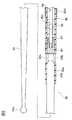
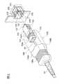
図1に示す本発明の一実施形態に係る医療器具用光コネクタとしてのバックコネクタ100を有する医療用スタイレット60は、たとえば図8に示すバルーンカテーテル20と共に用いられる。まず、図8に示すバルーンカテーテル20について説明する。  Amedical stylet 60 having aback connector 100 as an optical connector for a medical instrument according to an embodiment of the present invention shown in FIG. 1 is used together with, for example, theballoon catheter 20 shown in FIG. First, theballoon catheter 20 shown in FIG. 8 will be described.

図8に示すバルーンカテーテル20は、大動脈内バルーンポンピング法に用いるバルーンカテーテルであり、心臓の拍動に合わせて膨張および収縮するバルーン部22を有する。バルーン部22は、膜厚50〜150μm程度の薄膜で構成される。薄膜の材質は、特に限定されないが、抗血栓性および耐屈曲疲労特性に優れた材質であることが好ましく、たとえばポリウレタンなどにより構成される。  Aballoon catheter 20 shown in FIG. 8 is a balloon catheter used for an intra-aortic balloon pumping method, and has aballoon portion 22 that expands and contracts in accordance with the pulsation of the heart. Theballoon part 22 is comprised with the thin film about 50-150 micrometers in film thickness. The material of the thin film is not particularly limited, but is preferably a material excellent in antithrombogenicity and resistance to bending fatigue, and is made of, for example, polyurethane.

バルーン部22の外径および長さは、心機能の補助効果に大きく影響するバルーン部22の内容積と、動脈血管の内径などに応じて決定される。バルーン部22の内容積は、特に限定されないが、20〜50ccであり、バルーン部22の外径は、膨張時で12〜18mmが好ましく、長さは、150〜250mmが好ましい。  The outer diameter and length of theballoon portion 22 are determined according to the inner volume of theballoon portion 22 that greatly influences the assisting effect on the cardiac function, the inner diameter of the arterial blood vessel, and the like. The internal volume of theballoon part 22 is not particularly limited, but is 20 to 50 cc. The outer diameter of theballoon part 22 is preferably 12 to 18 mm at the time of inflation, and the length is preferably 150 to 250 mm.

このバルーン部22の遠位端部22aには、遠位端開口23が形成してある遠位端チップ部25が熱融着ないしは接着などの手段で取り付けてある。この遠位端チップ部25の内周側には、内管30の遠位端部が熱融着ないしは接着などの手段で取り付けてある。  A distalend tip portion 25 in which adistal end opening 23 is formed is attached to thedistal end portion 22a of theballoon portion 22 by means such as heat fusion or adhesion. A distal end portion of theinner tube 30 is attached to the inner peripheral side of the distalend tip portion 25 by means such as heat fusion or adhesion.

バルーン部22の近位端部22bには、外管24の遠位端部が接続してある。この外管24の内部に形成された圧力流体導通路29を通じて、バルーン部22の内部に、圧力流体が導入および導出され、バルーン部22が膨張および収縮するようになっている。バルーン部22と外管24との接続は、熱融着あるいは接着剤による接着により行われる。  A distal end portion of theouter tube 24 is connected to theproximal end portion 22 b of theballoon portion 22. The pressure fluid is introduced and led out into theballoon portion 22 through thepressure fluid passage 29 formed in theouter tube 24, and theballoon portion 22 is inflated and deflated. The connection between theballoon portion 22 and theouter tube 24 is performed by heat fusion or bonding with an adhesive.

内管30は、バルーン部22および外管24の内部を軸方向に延在し、後述するハンドル部42のワイヤ挿入口44に連通するようになっており、その内部には、バルーン部22の内部および外管24内に形成された圧力流体導通路29とは連通しないルーメン31が形成してある。  Theinner tube 30 extends in the axial direction inside theballoon portion 22 and theouter tube 24, and communicates with awire insertion port 44 of thehandle portion 42 described later. Alumen 31 that does not communicate with the pressurefluid communication path 29 formed in the inner andouter pipes 24 is formed.

バルーン部22内に位置する内管30は、バルーンカテーテル20を動脈内に挿入する際に、収縮した状態のバルーン部22が巻きつけられ、ルーメン31は、バルーン部22を都合良く動脈内に差し込むために用いるガイドワイヤを挿通する管腔としても用いられる。  When theballoon catheter 20 is inserted into the artery, theinner tube 30 positioned in theballoon portion 22 is wound around theballoon portion 22 in a deflated state, and thelumen 31 conveniently inserts theballoon portion 22 into the artery. It is also used as a lumen for inserting a guide wire used for the purpose.

外管24の近位端部には、患者の体外に設置されるハンドル部42が連結してある。ハンドル部42は、外管24と別体に成形され、熱融着あるいは接着などの手段で固着される。ハンドル部42には、外管24内の圧力流体導通路29およびバルーン部22内に圧力流体を導入または導出するための圧力流体導入出口46が形成される第1通路47と、内管30内に連通するワイヤ挿入口44が形成される第2通路45とが形成してある。  Ahandle portion 42 installed outside the patient's body is connected to the proximal end portion of theouter tube 24. Thehandle portion 42 is molded separately from theouter tube 24 and is fixed by means such as heat fusion or adhesion. Thehandle portion 42 includes afirst fluid passage 47 in which a pressurefluid introduction passage 46 for introducing or deriving a pressure fluid into theballoon portion 22 and a pressurefluid communication path 29 in theouter tube 24 and aninner tube 30 are formed. And asecond passage 45 in which awire insertion port 44 communicating with thesecond passage 45 is formed.

圧力流体導入出口46は、たとえば図示省略してある駆動装置の圧力流体コネクタチューブに接続され、この駆動装置により、流体圧がバルーン部内に導入または導出されるようになっている。導入される流体としては、特に限定されないが、駆動装置の駆動に応じて素早くバルーン部が拡張または収縮するように、粘性の小さいヘリウムガスなどが用いられる。また、駆動装置(IABP駆動装置)としては、特に限定されず、たとえば特公平2−39265号公報やWO2011/114779号公報に示すような装置が用いられる。  The pressurefluid introduction outlet 46 is connected to, for example, a pressure fluid connector tube of a driving device (not shown), and fluid pressure is introduced into or led out from the balloon portion by this driving device. The fluid to be introduced is not particularly limited, but helium gas having a low viscosity or the like is used so that the balloon portion can be quickly expanded or contracted according to the driving of the driving device. Further, the driving device (IABP driving device) is not particularly limited, and for example, a device as shown in Japanese Patent Publication No. 2-39265 and WO 2011/114779 is used.

本実施形態のハンドル部42では、圧力流体導入出口46が形成された第1通路47を外管24の軸心方向に沿ってストレート状に配置し、ワイヤ挿入口44が形成される第2通路45を、第1通路47の軸心に対して所定の傾きを以て配置するように構成してある。  In thehandle portion 42 of the present embodiment, thefirst passage 47 in which the pressurefluid introduction outlet 46 is formed is arranged in a straight shape along the axial direction of theouter tube 24, and the second passage in which thewire insertion port 44 is formed. 45 is arranged with a predetermined inclination with respect to the axis of thefirst passage 47.

また、本実施形態のハンドル部42では、第2通路45内に、内管30の端部を保持し、この内管30を、外管24の内壁に接するように偏心させて配置させるための第1内管端部保持具48と第2内管端部保持具50とが装着してある。ハンドル部42に形成される圧力流体導入出口46に連通する第1通路47を外管24の軸心方向に沿ってストレート状に配置してあるので、ワイヤ挿入口を外管の軸心方向に沿ってストレート状に配置する場合に比較し、圧力流体の流路抵抗を低減することが可能になると共に、バルーン部における拡張・収縮の応答性が向上する。  In thehandle portion 42 of the present embodiment, the end portion of theinner tube 30 is held in thesecond passage 45, and theinner tube 30 is arranged eccentrically so as to contact the inner wall of theouter tube 24. A first innertube end holder 48 and a second innertube end holder 50 are mounted. Since thefirst passage 47 communicating with the pressurefluid introduction outlet 46 formed in thehandle portion 42 is arranged in a straight shape along the axial direction of theouter tube 24, the wire insertion port extends in the axial direction of the outer tube. Compared to the case where the pressure fluid is arranged along the straight line, the flow resistance of the pressure fluid can be reduced, and the response of expansion / contraction in the balloon portion is improved.

ワイヤ挿入口44が形成してある第2内管端部保持具50の取付ポート52(第2通路45およびルーメン31に後述する挿入用ワイヤ80を通すためのポート)に対して、図1に示す医療用スタイレット60のフロントコネクタ70のポート接続部72が着脱自在に装着される。医療用スタイレット60の挿入用ワイヤ80は、内管30のルーメン31の内部に挿入可能になっている。なお、取付ポート52に対してポート接続部72を着脱自在に装着させる方法は、常法に従えばよく、たとえば、螺合などの手段を採用すればよい。  FIG. 1 shows the mountingport 52 of the second innertube end holder 50 in which thewire insertion port 44 is formed (port for inserting aninsertion wire 80 described later through thesecond passage 45 and the lumen 31). Aport connector 72 of thefront connector 70 of themedical stylet 60 shown is detachably mounted. Theinsertion wire 80 of themedical stylet 60 can be inserted into thelumen 31 of theinner tube 30. In addition, the method of attaching theport connection part 72 to theattachment port 52 in a detachable manner may be in accordance with a conventional method. For example, means such as screwing may be employed.

以下、医療用スタイレット60について詳細に説明する。図1に示すように、医療用スタイレット60は、挿入用ワイヤ80と、挿入用ワイヤ80の近位端部が取り付けられるコネクタ65とを有する。  Hereinafter, themedical stylet 60 will be described in detail. As shown in FIG. 1, themedical stylet 60 includes aninsertion wire 80 and aconnector 65 to which a proximal end portion of theinsertion wire 80 is attached.

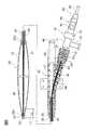
図2および図3に示すように、挿入用ワイヤ80は、中空ワイヤ82と、その中空ワイヤ82の遠位端に差し込まれて取り付けられている遠位端ワイヤ81を有する。遠位端ワイヤ81は、遠位端に向けてテーパ状に細くなっており、その最も遠位端には、遠位端付近のワイヤ81の外径よりも大きな径を持つ球状体81aが一体成形してある。この球状体81aをワイヤ81の遠位端に設けることで、挿入用ワイヤ80の遠位端を、図8に示す内管30のルーメン31内に差し込みやすくなり、挿入用ワイヤ80の遠位端部で内管30を傷つけるおそれが小さくなる。  As shown in FIGS. 2 and 3, theinsertion wire 80 has ahollow wire 82 and adistal end wire 81 inserted and attached to the distal end of thehollow wire 82. Thedistal end wire 81 is tapered toward the distal end, and aspherical body 81a having a diameter larger than the outer diameter of thewire 81 near the distal end is integrally formed at the most distal end. Molded. By providing thespherical body 81a at the distal end of thewire 81, the distal end of theinsertion wire 80 can be easily inserted into thelumen 31 of theinner tube 30 shown in FIG. The risk of damaging theinner tube 30 at the portion is reduced.

球状体81aの外径は、テーパ状のワイヤ81における最も大きな外径と同程度以下のサイズが好ましく、中空ワイヤ82の外径よりも小さいことが好ましい。遠位端ワイヤ81の長さ(中空ワイヤ82から飛び出している部分の長さ)L0は、特に限定されないが、好ましくは5〜50mmである。中空ワイヤ82の外径は、特に限定されないが、たとえば0.3〜0.7mmである。中空ワイヤ82の内径は、光学式圧力センサ84および光ファイバ88が挿入可能な内径であればよい。また、挿入用ワイヤ80の全長も、特に限定されないが、好ましくは50〜800mmである。  The outer diameter of thespherical body 81 a is preferably about the same as or smaller than the largest outer diameter of the taperedwire 81, and is preferably smaller than the outer diameter of thehollow wire 82. The length L0 of the distal end wire 81 (the length of the portion protruding from the hollow wire 82) L0 is not particularly limited, but is preferably 5 to 50 mm. Although the outer diameter of thehollow wire 82 is not specifically limited, For example, it is 0.3-0.7 mm. The inner diameter of thehollow wire 82 may be an inner diameter into which theoptical pressure sensor 84 and theoptical fiber 88 can be inserted. The total length of theinsertion wire 80 is not particularly limited, but is preferably 50 to 800 mm.

遠位端ワイヤ81の近位端部81bは、図3に示すように、中空ワイヤ82の取付遠位端部82aの内部に接合してある。これらの接合は、レーザ溶接、その他の溶接、あるいは接着剤による接合などでもよい。中空ワイヤ82の取付遠位端部82aの近くには、少なくとも1つ、好ましくは一対、または複数の開口部82bが設けてあり、開口部82bを通して、中空ワイヤ82の内部と外部とが連通可能になっている。  As shown in FIG. 3, theproximal end portion 81 b of thedistal end wire 81 is joined to the inside of the attachmentdistal end portion 82 a of thehollow wire 82. These joinings may be laser welding, other welding, joining by an adhesive, or the like. Near the attachmentdistal end portion 82a of thehollow wire 82, at least one, preferably a pair or a plurality ofopenings 82b are provided, and the inside and the outside of thehollow wire 82 can communicate with each other through theopenings 82b. It has become.

本実施形態では、遠位端ワイヤ81の近位端部は、開口部82bの近位端側縁部まで到達し、開口部82bに少しせり出しているが、必ずしも開口部82bまで到達しなくてもよい。ただし、この遠位端ワイヤ81の近位端部は、開口部82bを完全には塞がないようになっており、好ましくは開口部82bの開口面積を狭めないように、中空ワイヤ82の取付遠位端部82aの内部に接合してある。  In the present embodiment, the proximal end portion of thedistal end wire 81 reaches the proximal end side edge portion of theopening portion 82b and protrudes slightly to theopening portion 82b, but does not necessarily reach theopening portion 82b. Also good. However, the proximal end portion of thedistal end wire 81 does not completely block theopening portion 82b, and preferably thehollow wire 82 is attached so as not to reduce the opening area of theopening portion 82b. It is joined to the inside of thedistal end portion 82a.

開口部82bの近位端側縁部では、開口部82bから入り込む流体の圧力を検出する光学式圧力センサ84が中空ワイヤ82の内部に取り付けてある。光学式圧力センサ84の近位端には、光ファイバ88の遠位端が接合してある。図4に示すように、光ファイバ88の遠位端88aは、光学式圧力センサ84の基板本体84aの近位端側に形成してある凹部84b内に入り込み、接着剤87などにより基板本体84aに接合してある。  Anoptical pressure sensor 84 for detecting the pressure of the fluid entering from theopening 82b is attached to the inside of thehollow wire 82 at the edge on the proximal end side of theopening 82b. The distal end of theoptical fiber 88 is joined to the proximal end of theoptical pressure sensor 84. As shown in FIG. 4, thedistal end 88a of theoptical fiber 88 enters into arecess 84b formed on the proximal end side of thesubstrate body 84a of theoptical pressure sensor 84, and thesubstrate body 84a is bonded by an adhesive 87 or the like. Is joined.

基板本体84aは、たとえばガラスで構成してあり、その先端(遠位端)には、ダイヤフラム85が装着してあり、その背後に光の共振部を構成するように、空洞86が形成してある。ダイヤフラム85に圧力が加わることで、光ファイバ88を通して伝達する光の行路差などが変化し、ダイヤフラム85に加わる圧力を検出することができる。光学式圧力センサ84としては、特に限定されず、たとえば特表2008−524606号公報、特開2000−35369号公報、特表2014−507666号公報などに記載されたものを用いることができる。  Thesubstrate body 84a is made of, for example, glass. Adiaphragm 85 is attached to the tip (distal end) of thesubstrate body 84a, and a cavity 86 is formed behind thediaphragm 85 so as to form a light resonance portion. is there. By applying pressure to thediaphragm 85, the path difference of light transmitted through theoptical fiber 88 changes, and the pressure applied to thediaphragm 85 can be detected. Theoptical pressure sensor 84 is not particularly limited, and those described in, for example, JP-T 2008-524606, JP-A 2000-35369, JP-A 2014-507666, and the like can be used.

本実施形態では、圧力検出センサ84の圧力検出部であるダイヤフラム85が、中空ワイヤ82の開口部82bにおける近位端縁部に位置し、開口部82bを通して伝達する血液の血圧を正確に測定することが可能になっている。光学式圧力センサ84の近位端に接続してある光ファイバ88の外周には、たとえばポリイミド樹脂などによりコーティング層88bが形成してある。  In this embodiment, thediaphragm 85 which is a pressure detection part of thepressure detection sensor 84 is located at the proximal end edge of theopening 82b of thehollow wire 82, and accurately measures the blood pressure of blood transmitted through theopening 82b. It is possible. On the outer periphery of theoptical fiber 88 connected to the proximal end of theoptical pressure sensor 84, acoating layer 88b is formed of, for example, polyimide resin.

光学式圧力センサ84の近くに位置する光ファイバ88の遠位端近傍は、隔壁リング83により中空ワイヤ82の内部に固定される。隔壁リング83を中空ワイヤ82の内部で所定位置に固定するために、図2および図3に示すように、中空ワイヤ82の開口部82bから所定位置に、接着用孔82cが1つ以上形成してある。その接着用孔82cを通して、接着剤を注入することで、隔壁リング83を中空ワイヤ82の内部で開口部82bから近位端側に所定位置に固定することが容易になり、開口部82bと光学式圧力センサ84との位置決めも同時に行うことができる。光学式圧力センサ84で検出された圧力は、光ファイバ88を通して光信号として送信することができる。  The vicinity of the distal end of theoptical fiber 88 located near theoptical pressure sensor 84 is fixed inside thehollow wire 82 by thepartition ring 83. In order to fix thepartition ring 83 at a predetermined position inside thehollow wire 82, one ormore bonding holes 82c are formed at predetermined positions from theopening 82b of thehollow wire 82, as shown in FIGS. It is. By injecting an adhesive through thebonding hole 82c, it becomes easy to fix thepartition ring 83 in a predetermined position from theopening 82b to the proximal end side inside thehollow wire 82. The positioning with thepressure sensor 84 can be performed simultaneously. The pressure detected by theoptical pressure sensor 84 can be transmitted as an optical signal through theoptical fiber 88.

本実施形態では、遠位端ワイヤ81と中空ワイヤ82とは、たとえば、ステンレス鋼やニッケル・チタン合金などの金属で構成してあり、これらは同一の材質で構成してもよく、あるいは異なる材質で構成してもよい。図4に示すように、中空ワイヤ82の外周には、たとえばPTFEなどのフッ素樹脂からなるコーティング層82dを施してもよい。  In the present embodiment, thedistal end wire 81 and thehollow wire 82 are made of metal such as stainless steel or nickel / titanium alloy, and these may be made of the same material or different materials. You may comprise. As shown in FIG. 4, acoating layer 82 d made of a fluororesin such as PTFE may be applied to the outer periphery of thehollow wire 82.

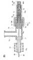
図1に示すように、コネクタ65は、中空ワイヤ82の近位端部が取り付けられたフロントコネクタ70と、バックコネクタ(本実施形態の医療器具用光コネクタ)100と、これらを連結するケーブル90とを有する。フロントコネクタ70は、図8に示すように、カテーテルとしてのバルーンカテーテル20のルーメン31に挿入用ワイヤ80を通すための取付ポート52に連結されるポート接続部72を有する。ポート接続部72は、フロントコネクタ70のフロントコネクタ本体71の遠位端部に形成してあり、さらに、フロントコネクタ本体71には、分岐ポート73が形成してある。なお、フロントコネクタ70と中空ワイヤ82(挿入用ワイヤ80)との接続は、着脱自在な接続としてもよいし、着脱不可に固定してもよいが、フロントコネクタ70および中空ワイヤ82内の光ファイバ88の導通を長期間確実に保つ観点からは、着脱不可に固定して接続することが好ましい。  As shown in FIG. 1, theconnector 65 includes afront connector 70 to which the proximal end of thehollow wire 82 is attached, a back connector (optical connector for a medical instrument of this embodiment) 100, and acable 90 that connects them. And have. As shown in FIG. 8, thefront connector 70 has aport connection portion 72 connected to anattachment port 52 for passing theinsertion wire 80 through thelumen 31 of theballoon catheter 20 as a catheter. Theport connection portion 72 is formed at the distal end portion of thefront connector body 71 of thefront connector 70, and thebranch port 73 is formed in thefront connector body 71. The connection between thefront connector 70 and the hollow wire 82 (insertion wire 80) may be a detachable connection or may be fixed so as not to be detachable, but the optical fiber in thefront connector 70 and thehollow wire 82 may be fixed. From the viewpoint of reliably maintaining the continuity of 88 for a long period of time, it is preferable that the connection is fixed so as not to be detachable.

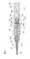
図5に示すように、ポート接続部72の内部には、略同芯状に、フラッシュ用ノズル72aが取り付けてある。フラッシュ用ノズル72aの内部は、分岐ポート73の内部に連通してある。分岐ポート73から導入される生理食塩水や抗血液凝固薬液などの液体は、図8に示すフラッシュ用ノズル72aの先端からワイヤ挿入口44内部に導入され、そこから内管30のルーメン31を通して挿入用ワイヤ80の外側を流れ、内管30の遠位端開口23まで導かれるようになっている。  As shown in FIG. 5, aflush nozzle 72 a is attached inside theport connection portion 72 so as to be substantially concentric. The inside of theflash nozzle 72 a communicates with the inside of thebranch port 73. Liquids such as physiological saline and anticoagulant solution introduced from thebranch port 73 are introduced into thewire insertion port 44 from the tip of theflush nozzle 72a shown in FIG. 8, and inserted through thelumen 31 of theinner tube 30 therefrom. It flows outside thewire 80 and is led to the distal end opening 23 of theinner tube 30.

図5に示すように、フロントコネクタ本体71の近位端には、連結ポート74が形成してあり、連結ポート74には、フェルール保持部75が連結してある。図6および図7に示すように、フェルール保持部75の内部には、挿入用ワイヤ80の中空ワイヤ82の内部に装着してある光ファイバ88の近位端部をケーブル90内の光ファイバ88Aに連結するための一対のフェルール76,77がスリーブ78の内部で突き合わされて配置してある。また、この一対のフェルール76,77およびスリーブ78の外周側には、たとえばステンレス鋼などの金属で構成してあるパイプ78aが被せてあり、このパイプ78aの内部は、光学部品シール用接着剤などのシール材78bで封止されている。中空ワイヤ82の内部に装着してある光ファイバ88と、ケーブル90内の光ファイバとを、それぞれ別体の光ファイバで構成し、フロントコネクタ本体71内で接続することで、中空ワイヤ82部分とケーブル90部分とを個別の製造工程で製造することが可能になり、医療用スタイレット60の生産性が良好なものとなる。また、これらの光ファイバ88,88Aとして、互いに種類や径が異なる光ファイバを用いることも可能となり、たとえば、中空ワイヤ82の径を細くすることを目的に、中空ワイヤ82内の光ファイバ88として、特別に径を細くした高価な光ファイバを用い、ケーブル90内の光ファイバ88Aとしては、汎用的な安価な光ファイバを用いることもできる。なお、フェルール76,77は、異なる光ファイバ88,88Aの端部同士を相互に光信号の伝達可能に接続することを容易にするために用いられるが、必ずしも用いる必要はなく、たとえば、光ファイバ88,88Aの端部同士を融着などの手段により直接接続してもよい。  As shown in FIG. 5, aconnection port 74 is formed at the proximal end of the front connectormain body 71, and aferrule holding portion 75 is connected to theconnection port 74. As shown in FIGS. 6 and 7, theferrule holding part 75 has anoptical fiber 88 </ b> A in thecable 90 that is connected to the proximal end of theoptical fiber 88 attached to thehollow wire 82 of theinsertion wire 80. A pair offerrules 76 and 77 are connected to each other inside thesleeve 78. Further, apipe 78a made of a metal such as stainless steel is covered on the outer peripheral side of the pair offerrules 76 and 77 and thesleeve 78, and the inside of thepipe 78a is an adhesive for sealing an optical component or the like. It is sealed with a sealingmaterial 78b. Theoptical fiber 88 mounted inside thehollow wire 82 and the optical fiber in thecable 90 are configured as separate optical fibers, and are connected in the front connectormain body 71. Thecable 90 portion can be manufactured in a separate manufacturing process, and the productivity of themedical stylet 60 is improved. Also, as theseoptical fibers 88 and 88A, optical fibers having different types and diameters can be used. For example, for the purpose of reducing the diameter of thehollow wire 82, theoptical fiber 88 in thehollow wire 82 is used. Alternatively, an expensive optical fiber with a particularly small diameter may be used, and a general-purpose inexpensive optical fiber may be used as theoptical fiber 88A in thecable 90. Theferrules 76 and 77 are used to facilitate connecting the ends of the differentoptical fibers 88 and 88A to each other so that an optical signal can be transmitted to each other. However, theferrules 76 and 77 are not necessarily used. The ends of 88 and 88A may be directly connected by means such as fusion.

図6に示すように、光ファイバ88Aの遠位端部が連結されたフェルール77の近位端は、栓部材79の遠位端に取り付けてあり、栓部材79の近位端側筒部79aは、ケーブル90内で光ファイバ88Aの周囲に光ファイバ88Aを支持および保護する目的で設けられたアラミド繊維93とかしめリングを用いたかしめ等の手段によって接続され、さらに、その外側から、ケーブル90を構成するチューブ本体91の遠位端91aともかしめリングを用いたかしめ等の手段によって接続される。フェルール保持部75の収容筒部75bの内部には、一対のフェルール76,77およびスリーブ78が内部に封止されたパイプ78aをさらに封止するように、たとえば紫外線硬化型接着剤の硬化物などで構成される充填物75gが充填される。  As shown in FIG. 6, the proximal end of theferrule 77 to which the distal end portion of theoptical fiber 88A is connected is attached to the distal end of theplug member 79, and the proximal end sidetubular portion 79a of theplug member 79 is attached. Is connected to thearamid fiber 93 provided for the purpose of supporting and protecting theoptical fiber 88A around theoptical fiber 88A in thecable 90 by means such as caulking using a caulking ring. Are connected to thedistal end 91a of the tubemain body 91 constituting the above by means such as caulking using a caulking ring. A pair offerrules 76 and 77 and apipe 78a in which asleeve 78 is sealed are further sealed in thehousing cylinder portion 75b of theferrule holding portion 75, for example, a cured product of an ultraviolet curable adhesive or the like. Filled with 75 g of filling material.

フェルール保持部75の近位端には、その内面の周方向に延在する凸部75fが設けられていて、その凸部75fが存在することにより、栓部材79の近位端側筒部79aとケーブル90との接続部分がフェルール保持部75の近位端側から抜けることが防止されて、フェルール保持部75とケーブル90との接続が確実なものとされている。また、フェルール保持部75の遠位端には、挿入筒部75cと、その外周に位置する外周筒部75dとが形成してあり、これらの間の隙間75eに、図5に示す連結ポート74が入り込むことによって、フロントコネクタ本体71とフェルール保持部75とが連結されている。なお、フロントコネクタ本体71とフェルール保持部75との連結は、フェルール保持部75の収容筒部75b内での光ファイバ88,88Aの接続および収容筒部75b内への充填物75gの充填が完了した後に行うことが望ましい。また、フロントコネクタ本体71とフェルール保持部75との連結に、螺合や接着などの手段を用いてもよい。フェルール保持部75の挿入筒部75cおよび収容筒部75bの内部では、一対のフェルール76,77およびスリーブ78が配置されるが、その周囲は、シール材78bおよび充填物75gで満たされているために、分岐ポート73から流入される液体は、挿入筒部75cおよび収容筒部75bの内部に入り込むことはなく、その遠位端側に配置されるフラッシュ用ノズル72aから、図8に示すハンドル部42のワイヤ挿入口44に吐出されるようになっている。したがって、一対のフェルール76,77を用いて接続された光ファイバ88,88Aの接続部は、ポート接続部72と分岐ポート73との間を流れる液体と接触することがないので、光ファイバ88,88Aは、その液体の影響を受けることなく、確実な接続が確保される。  The proximal end of theferrule holding portion 75 is provided with aconvex portion 75f extending in the circumferential direction of its inner surface, and the presence of theconvex portion 75f allows the proximal end sidecylindrical portion 79a of theplug member 79 to be provided. The connection part between thecable 90 and thecable 90 is prevented from coming off from the proximal end side of theferrule holding part 75, and the connection between theferrule holding part 75 and thecable 90 is ensured. In addition, aninsertion tube portion 75c and anouter tube portion 75d located on the outer periphery thereof are formed at the distal end of theferrule holding portion 75, and aconnection port 74 shown in FIG. The front connectormain body 71 and theferrule holding part 75 are connected to each other. The connection between the front connectormain body 71 and theferrule holding part 75 is completed when theoptical fibers 88 and 88A are connected in theaccommodating cylinder part 75b of theferrule holding part 75 and the fillingmaterial 75g is filled in theaccommodating cylinder part 75b. It is desirable to do this after. Further, a means such as screwing or adhesion may be used for connection between the front connectormain body 71 and theferrule holding portion 75. A pair offerrules 76 and 77 and asleeve 78 are arranged inside theinsertion cylinder part 75c and theaccommodation cylinder part 75b of theferrule holding part 75, but the periphery thereof is filled with the sealingmaterial 78b and thefiller 75g. In addition, the liquid flowing in from thebranch port 73 does not enter the inside of theinsertion cylinder part 75c and theaccommodation cylinder part 75b, but from theflush nozzle 72a arranged on the distal end side thereof, the handle part shown in FIG. 42 is discharged into thewire insertion port 44. Therefore, the connection portion of theoptical fibers 88 and 88A connected using the pair offerrules 76 and 77 does not come into contact with the liquid flowing between theport connection portion 72 and thebranch port 73. The 88A is secured without being affected by the liquid.

図1に示すように、ケーブル90の両端の外周には、応力緩和部材としてのストレインリリーフ92および94が装着してある。ストレインリリーフ92および94は、例えば熱可塑性エラストマーなどにより形成された、一方の端部から他方の端部に向かうほど外径が小さくなっている略筒状の部材であり、その外周面には、径方向に沿って応力緩和溝95が設けられている。そして、一方のストレインリリーフ92は、外径の大きいほうの端部を遠位端として、フロントコネクタ70のフェルール保持部75の近位端に連結してあり、ケーブル90の遠位端を覆う。他方のストレインリリーフ94は、外径の大きいほうの端部を近位端として、バックコネクタ100のカバー部材106の遠位端に連結してあり、ケーブル90の近位端を覆う。  As shown in FIG. 1, strain reliefs 92 and 94 as stress relaxation members are attached to the outer periphery of both ends of thecable 90. The strain reliefs 92 and 94 are substantially cylindrical members formed of, for example, a thermoplastic elastomer and having an outer diameter that decreases from one end to the other end. Astress relaxation groove 95 is provided along the radial direction. Onestrain relief 92 is connected to the proximal end of theferrule holding portion 75 of thefront connector 70 with the end having the larger outer diameter as the distal end, and covers the distal end of thecable 90. Theother strain relief 94 is connected to the distal end of thecover member 106 of theback connector 100 with the end having the larger outer diameter as the proximal end, and covers the proximal end of thecable 90.

図5および図6に示すように、ケーブル90を構成する可撓性チューブ91の内部には、光ファイバ88Aが通してあり、光ファイバ88Aの近位端は、図11に示すように、バックコネクタ100のカバー部材106により保持してあるバックコネクタ本体(コネクタ本体)104の端フェルール102に連結してある。  As shown in FIGS. 5 and 6, anoptical fiber 88A is passed through aflexible tube 91 constituting thecable 90, and the proximal end of theoptical fiber 88A is connected to the back as shown in FIG. It is connected to theend ferrule 102 of the back connector main body (connector main body) 104 held by thecover member 106 of theconnector 100.

図10A、図10Bおよび図11に示すように、カバー部材106の遠位端側外周には、その他の部分よりも外径が小さくなっている把持部106aが形成してあり、操作者の指で摘みやすくなっている。把持部106aの内部には、ストレインリリーフ94の近位端部94aが位置し、カバー部材106の遠位端に形成してある第1内方凸部130が、ストレインリリーフ94の近位端部94aに形成してある応力緩和溝95に係合してある。ストレインリリーフ94の近位端部94aは、カバー部材106の内部で、たとえば接着剤などにより固定してもよい。  As shown in FIGS. 10A, 10B, and 11, agrip portion 106a having an outer diameter smaller than that of the other portion is formed on the outer periphery on the distal end side of thecover member 106. It is easy to pick with. Aproximal end portion 94 a of thestrain relief 94 is located inside thegrip portion 106 a, and a first inwardconvex portion 130 formed at the distal end of thecover member 106 is a proximal end portion of thestrain relief 94. It is engaged with astress relaxation groove 95 formed in 94a. Theproximal end portion 94a of thestrain relief 94 may be fixed inside thecover member 106 with, for example, an adhesive.

カバー部材106は、たとえば合成樹脂などにより形成され、特に把持部106aでは、操作者が指で摘みやすくするために柔軟性を持たせてもよい。また、カバー部材106は、図12に示すように、一対の半割体106Aおよび106Bが組み合わされて構成される。図10Bは、一方の半割体106Bを取り除き、他方の半割体106Aを底面側から見た状態を示すが、取り除かれた他方の半割体106Bも同様な構造を有している。  Thecover member 106 is formed of, for example, a synthetic resin, and may be flexible so that the operator can easily pick it with a finger, particularly in thegrip portion 106a. Further, as shown in FIG. 12, thecover member 106 is configured by combining a pair ofhalves 106A and 106B. FIG. 10B shows a state in which onehalf 106B is removed and theother half 106A is viewed from the bottom side, but theother half 106B that has been removed has a similar structure.

図10Bに示すように、カバー部材106の近位端内部には、一対の第2内方凸部132が一体に形成してあり、それぞれの第2内方凸部132は、コネクタ本体104の摺動スリーブ104Aの遠位端104aに形成してある摘まみ用凹部124に係合して、コネクタ本体104の遠位端104aをカバー部材106の内部に固定可能にしてある。コネクタ本体104の近位端底面(図10Aおよび図10B参照)には、一対のコネクタ側電気接続端子110が装着してある。  As shown in FIG. 10B, a pair of second inwardconvex portions 132 are integrally formed inside the proximal end of thecover member 106, and each second inwardconvex portion 132 is formed on theconnector body 104. Thedistal end 104a of theconnector body 104 can be fixed to the inside of thecover member 106 by engaging with aknob recess 124 formed at thedistal end 104a of the slidingsleeve 104A. A pair of connector-sideelectrical connection terminals 110 are attached to the bottom surface of the proximal end of the connector main body 104 (see FIGS. 10A and 10B).

図11に示すように、コネクタ側電気接続端子110は、機器側電気接続端子210に着脱自在に接続可能になっている。機器側電気接続端子210は、コネクタ本体104の端フェルール102の近位端102aが着脱自在に連結される受け側フェルール202が固定してある機器側接続部204の基板211に装着してある。  As shown in FIG. 11, the connector-sideelectrical connection terminal 110 can be detachably connected to the device-sideelectrical connection terminal 210. The device-sideelectrical connection terminal 210 is mounted on thesubstrate 211 of the device-side connection portion 204 to which the receiving-side ferrule 202 to which theproximal end 102a of theend ferrule 102 of the connectormain body 104 is detachably connected is fixed.

図12に示すように、機器側接続部204は、たとえば雌型ソケット200として構成される。コネクタ本体104の近位端は、雄型ソケットを構成する。そのため、雌型ソケット200にバックコネクタ100のコネクタ本体104の近位端を差し込むことで、端フェルール102と受け側フェルール202との光接続が可能になり、同時に、コネクタ側電気接続端子110と機器側電気接続端子210との電気的接続が可能になる。  As illustrated in FIG. 12, the device-side connection unit 204 is configured as, for example, afemale socket 200. The proximal end of theconnector body 104 constitutes a male socket. Therefore, by inserting the proximal end of the connectormain body 104 of theback connector 100 into thefemale socket 200, theend ferrule 102 and the receivingferrule 202 can be optically connected, and at the same time, the connector sideelectrical connection terminal 110 and the device The electrical connection with the sideelectrical connection terminal 210 becomes possible.

図11に示すように、機器側接続部204の内部では、受け側フェルール202に光ファイバ88Bが接続してあり、機器側電気接続端子210に基板211の電気配線が接続してある。機器側接続部204を含む雌型ソケット200は、図示省略してあるIABP駆動装置、または血圧測定表示装置などに組み込まれている。  As shown in FIG. 11, theoptical fiber 88 </ b> B is connected to the receivingferrule 202 and the electrical wiring of thesubstrate 211 is connected to the equipment sideelectrical connection terminal 210 inside the equipmentside connection unit 204. Thefemale socket 200 including the deviceside connection unit 204 is incorporated in an IABP driving device, a blood pressure measurement display device, or the like that is not shown.

雌型ソケット200の光ファイバ88Bに伝達された光信号は、図3および図4に示す光学式圧力センサ84により検出された圧力信号を含む。その光信号は、図示省略してあるIABP駆動装置、または血圧測定表示装置などにより、血圧信号に変換され、血圧データとして、IABP駆動装置の駆動信号に利用される。具体的には、圧力センサで測定された血圧変動データに基づき、心臓の拍動に応じてポンプ装置を制御し、0.4〜2秒の短周期で、図8に示すバルーン部22を膨張および収縮させるようになっている。あるいは、その血圧データは、リアルタイムで、表示することも可能である。  The optical signal transmitted to theoptical fiber 88B of thefemale socket 200 includes the pressure signal detected by theoptical pressure sensor 84 shown in FIGS. The optical signal is converted into a blood pressure signal by an IABP driving device (not shown) or a blood pressure measurement display device, and used as a blood pressure data for a driving signal of the IABP driving device. Specifically, based on the blood pressure fluctuation data measured by the pressure sensor, the pump device is controlled according to the pulsation of the heart, and theballoon portion 22 shown in FIG. 8 is inflated in a short cycle of 0.4 to 2 seconds. And is supposed to shrink. Alternatively, the blood pressure data can be displayed in real time.

図11に示すように、カバー部材106の近位端側内周には、凹部106bが形成してあり、その凹部106b内に、コネクタ本体104(摺動スリーブ104A)の底面部に固定してあるメモリ素子としてのICチップ112を配置してある。ICチップ112は、コネクタ本体104の背面を通して、コネクタ側電気接続端子110に接続してある。ICチップ112には、たとえば医療用スタイレット60または医療用スタイレット60が連結されるカテーテル(バルーンカテーテル20)に関連するデータなどを記憶することができ、電気接続端子110および210を通して、そのデータを読み取り可能になっている。また、電気接続端子110および210を通して、ICチップ112の内部に保存してあるデータを書き換えることも可能である。  As shown in FIG. 11, arecess 106b is formed on the inner periphery of thecover member 106 at the proximal end side, and thecover member 106 is fixed to the bottom surface of the connector body 104 (slidingsleeve 104A) in therecess 106b. AnIC chip 112 as a certain memory element is arranged. TheIC chip 112 is connected to the connector sideelectrical connection terminal 110 through the back surface of the connectormain body 104. TheIC chip 112 can store, for example, data related to themedical stylet 60 or a catheter (balloon catheter 20) to which themedical stylet 60 is coupled, and the data is transmitted through theelectrical connection terminals 110 and 210. Can be read. In addition, data stored in theIC chip 112 can be rewritten through theelectrical connection terminals 110 and 210.

ICチップ112に保存することができるデータとしては、特に限定されないが、光学式圧力センサ84の個体差を補償するためのデータ、バルーン部の拡張外径および容量と製品番号に関するデータ、あるいはバルーンカテーテルのタイプなどがある。バルーンカテーテルのタイプとしては、ショートバルーンタイプ、ロングバルーンタイプ、その他の特殊形状タイプなどがある。  The data that can be stored in theIC chip 112 is not particularly limited, but is data for compensating for individual differences of theoptical pressure sensor 84, data on the expansion outer diameter and capacity of the balloon portion and product number, or balloon catheter. There are other types. The types of balloon catheter include a short balloon type, a long balloon type, and other special shape types.

図示省略してあるIABP駆動装置では、ICチップ112に記憶してあるデータに基づき、駆動装置からバルーンカテーテルに送られる圧力流体の流量調整を自動的に行うこともできる。すなわち、バルーン部の容量が小さい場合には、バルーンカテーテルに送られる圧力流体の流量も小さくなる。  In the IABP driving device (not shown), the flow rate of the pressure fluid sent from the driving device to the balloon catheter can be automatically adjusted based on the data stored in theIC chip 112. That is, when the volume of the balloon portion is small, the flow rate of the pressure fluid sent to the balloon catheter is also small.

また、使用済みのバルーンカテーテルと共に用いられた医療用スタイレット60のICチップ112に書き込まれるデータとしては、特に限定されないが、たとえばバルーンカテーテルを実際に駆動した駆動装置の識別番号などが例示される。その場合には、図8に示すバルーンカテーテル20および医療用スタイレット60を駆動装置から取り外した後においても、そのバルーンカテーテル20が用いられた駆動装置を容易に特定することができる。  Further, the data written to theIC chip 112 of themedical stylet 60 used together with the used balloon catheter is not particularly limited. For example, the identification number of the driving device that actually drives the balloon catheter is exemplified. . In that case, even after theballoon catheter 20 and themedical stylet 60 shown in FIG. 8 are removed from the drive device, the drive device using theballoon catheter 20 can be easily identified.

そのため、そのICチップ112のデータを読み取り、さらに、そのデータから特定される駆動装置のデータを組み合わせることで、臨床研究やトラブル対応時に、使用されたバルーンカテーテル20の駆動状態を、後で正確に把握することが容易になり、駆動状態の解析に要する時間を短縮することができる。  Therefore, by reading the data of theIC chip 112 and combining the data of the driving device specified from the data, the driving state of theballoon catheter 20 used at the time of clinical research or troubleshooting can be accurately determined later. It becomes easy to grasp and the time required for the analysis of the driving state can be shortened.

なお、ICチップ112のメモリ容量に余裕があるときには、ICチップ112に書き込まれるデータは、たとえばバルーンカテーテル20を実際に駆動した駆動装置の駆動状態の全てのデータ、あるいはその一部のデータであってもよい。駆動状態に関するデータとしては、たとえば駆動期間中における心電図、血圧、駆動圧などの波形データや、駆動期間中のイベントデータなどである。  When the memory capacity of theIC chip 112 has a margin, the data written to theIC chip 112 is, for example, all data of the driving state of the driving device that actually drives theballoon catheter 20 or a part of the data. May be. Examples of data relating to the driving state include waveform data such as an electrocardiogram, blood pressure, and driving pressure during the driving period, and event data during the driving period.

このようなデータをICチップ112から読み取ることにより、臨床研究やトラブル対応時に、使用されたバルーンカテーテル20の駆動状態を、後で正確に把握することが容易になり、駆動状態の解析に要する時間を短縮することができる。  Reading such data from theIC chip 112 makes it easy to accurately grasp the driving state of the usedballoon catheter 20 later during clinical research or troubleshooting, and the time required for analyzing the driving state. Can be shortened.

図11に示すように、本実施形態では、カバー部材106がコネクタ本体104の遠位端部を囲むように保持することで、操作者は、カバー部材106あるいはストレインリリーフ94を片手で把持して、コネクタ本体104の近位端を、雌型ソケット200の機器側接続部204に着脱自在に接続することが容易になる。しかも、コネクタ本体104の近位端を、機器側接続部204に接続することのみで、端フェルール102と受け側フェルール202との接続が成されると同時に、コネクタ側電気接続端子110と機器側電気接続端子210との接続が成される。  As shown in FIG. 11, in this embodiment, thecover member 106 is held so as to surround the distal end portion of theconnector body 104, so that the operator holds thecover member 106 or thestrain relief 94 with one hand. It becomes easy to detachably connect the proximal end of the connectormain body 104 to the deviceside connection portion 204 of thefemale socket 200. Moreover, the connection between theend ferrule 102 and the receivingferrule 202 is made only by connecting the proximal end of theconnector body 104 to the deviceside connection portion 204, and at the same time, the connector sideelectrical connection terminal 110 and the device side. Connection to theelectrical connection terminal 210 is made.

図12に示すように、機器側接続部204は、雌型ソケット200であり、その内部には、一対の係合片220が配置してある。係合片220は、たとえば弾性変形可能な合成樹脂で構成され、係合片220のフック部は、コネクタ本体104の両側に形成してある係合凹部122に着脱自在に係合可能になっている。係合凹部122は、コネクタ本体104の摺動スリーブ104Aの内部に装着してあるフェルールケーシング120に形成してある。フェルールケーシング120は、その内部に端フェルール102を保持し、摺動スリーブ104Aの内部に、所定の範囲で軸方向移動自在に装着してある。また、ケーブル90は、フェルールケーシング120に接続してあり、コネクタ本体104の摺動スリーブ104Aに対して、所定の範囲で軸方向移動自在である。雌型ソケット200の係合片220は、摺動スリーブ104Aがフェルールケーシング120に対して接続方向に押し込まれた状態でコネクタ本体104が雌型ソケット200に挿し込まれたときにのみ、摺動スリーブ104Aを乗り越えて、フェルールケーシング120の係合凹部122と係合できるようになっていて、それ以外の状態で挿し込まれても、摺動スリーブ104Aが邪魔となって、係合凹部122と係合できないようになっている。  As shown in FIG. 12, the apparatusside connection part 204 is thefemale socket 200, and a pair ofengagement pieces 220 are disposed therein. Theengagement piece 220 is made of, for example, an elastically deformable synthetic resin, and the hook portions of theengagement piece 220 are detachably engageable withengagement recesses 122 formed on both sides of the connectormain body 104. Yes. The engagingrecess 122 is formed in theferrule casing 120 mounted inside the slidingsleeve 104 </ b> A of the connectormain body 104. Theferrule casing 120 holds theend ferrule 102 therein, and is mounted inside the slidingsleeve 104A so as to be axially movable within a predetermined range. Thecable 90 is connected to theferrule casing 120, and is movable in the axial direction within a predetermined range with respect to the slidingsleeve 104A of the connectormain body 104. Theengagement piece 220 of thefemale socket 200 is a sliding sleeve only when the connectormain body 104 is inserted into thefemale socket 200 with the slidingsleeve 104A pushed into theferrule casing 120 in the connecting direction. 104 A can be overcome and engaged with theengaging recess 122 of theferrule casing 120, and even if it is inserted in any other state, the slidingsleeve 104 A becomes a hindrance and engages with theengaging recess 122. Can not be matched.

図1に示す本実施形態に係る医療用スタイレット60は、たとえば図8に示すバルーンカテーテル20と共に用いられる。バルーンカテーテル20は、それを体内に導入するためのルーメン31に、図示しないガイドワイヤを通して体内の所定位置に搬送される。  Amedical stylet 60 according to this embodiment shown in FIG. 1 is used together with, for example, theballoon catheter 20 shown in FIG. Theballoon catheter 20 is conveyed to a predetermined position in the body through a guide wire (not shown) to alumen 31 for introducing theballoon catheter 20 into the body.

その後、ルーメン31からガイドワイヤが取り去られた後に、図8に示すように、医療用スタイレット60におけるフロントコネクタ70のポート接続部72が、バルーンカテーテル20のハンドル部42の取付ポート52に取り付けられる。その結果、内管30のルーメン31に遠位端ワイヤ81側から挿入用ワイヤ80を挿入することができる。  Thereafter, after the guide wire is removed from thelumen 31, theport connection portion 72 of thefront connector 70 in themedical stylet 60 is attached to theattachment port 52 of thehandle portion 42 of theballoon catheter 20, as shown in FIG. It is done. As a result, theinsertion wire 80 can be inserted into thelumen 31 of theinner tube 30 from thedistal end wire 81 side.

図2および図3に示すように、遠位端ワイヤ81は、中空ワイヤ82の遠位端部に取り付けられ、中空ワイヤ82とは異なる材質や特性や形状で成形することができ、たとえば柔軟性に優れ、図8に示すルーメン31の内部を都合良く案内されて目的とする位置に容易に到達することができる。  As shown in FIGS. 2 and 3, thedistal end wire 81 is attached to the distal end portion of thehollow wire 82, and can be formed with a different material, characteristic, or shape from thehollow wire 82. It can be easily guided to the inside of thelumen 31 shown in FIG. 8 and easily reach the target position.

また、医療用スタイレット60をバルーンカテーテル20に挿入することで、バルーンカテーテル20の剛性が高くなり、バルーンカテーテル20のバルーン部22が血流により押戻されるおそれが減少し、キンク(折れ)も有効に防止できる。  Further, by inserting themedical stylet 60 into theballoon catheter 20, the rigidity of theballoon catheter 20 is increased, the possibility that theballoon portion 22 of theballoon catheter 20 is pushed back by the blood flow is reduced, and kinking (breaking) is also caused. It can be effectively prevented.

さらに、本実施形態では、図3に示すように、光学式圧力センサ84が、遠位端ワイヤ81の後側に設けられるために、図8および図9に示すように、開口部82bの近位端縁部の位置(光学式圧力センサ84の位置と略同じ)を、バルーンカテーテル20の遠位端開口23から近位端に向けて所定距離L2で内管30の内側に位置させることができる。その結果、血栓などの影響を受けることなく、しかも電気ノイズに影響されることなく、光学式圧力センサ84により血圧などを正確に測定することが可能である。  Furthermore, in this embodiment, as shown in FIG. 3, since theoptical pressure sensor 84 is provided on the rear side of thedistal end wire 81, as shown in FIGS. The position of the distal end edge (substantially the same as the position of the optical pressure sensor 84) may be positioned inside theinner tube 30 at a predetermined distance L2 from the distal end opening 23 of theballoon catheter 20 toward the proximal end. it can. As a result, blood pressure and the like can be accurately measured by theoptical pressure sensor 84 without being affected by blood clots and without being affected by electrical noise.

そして、本実施形態では、図8および図9に示すように、内管30のルーメン31に医療用スタイレット60の挿入用ワイヤ80を挿入して装着したとき、すなわち、医療用スタイレット60のフロントコネクタ70のポート接続部72がバルーンカテーテル20のハンドル部42における第2内管端部保持具50の取付ポート52に取り付けられたとき、遠位端ワイヤ81の遠位端81aの位置は、バルーンカテーテル20の遠位端開口23より外部に飛び出さないようにされていて、遠位端81aは遠位端開口23より近位端に向けて所定距離L1の位置にある。所定距離L1は、バルーンの駆動などによる振動があっても遠位端81aが遠位端開口23から突出することを防止し、かつ、光学式圧力センサ84によって、より正確な圧力を測定する観点から、好ましくは、30〜250mmである。また、所定距離L2は、好ましくは、31mm以上である。  In this embodiment, as shown in FIGS. 8 and 9, when theinsertion wire 80 of themedical stylet 60 is inserted and attached to thelumen 31 of theinner tube 30, that is, themedical stylet 60 is attached. When theport connection portion 72 of thefront connector 70 is attached to theattachment port 52 of the second innertube end holder 50 in thehandle portion 42 of theballoon catheter 20, the position of thedistal end 81a of thedistal end wire 81 is Theballoon catheter 20 is prevented from jumping out from the distal end opening 23 of theballoon catheter 20, and thedistal end 81a is located at a predetermined distance L1 from the distal end opening 23 toward the proximal end. The predetermined distance L1 prevents thedistal end 81a from protruding from the distal end opening 23 even when there is vibration due to the driving of the balloon and the like, and theoptical pressure sensor 84 measures a more accurate pressure. Therefore, the thickness is preferably 30 to 250 mm. The predetermined distance L2 is preferably 31 mm or more.

本実施形態では、図8に示す分岐ポート73から生理食塩水や抗血液凝固薬液などの液体を導入することで、その液体がバルーンカテーテル20のルーメン31内に位置する光学式圧力センサ84の周囲にまで到達し、センサ84の周囲で血栓などが生じることを抑制することができ、血圧などを正確に検出することができる。  In this embodiment, by introducing a liquid such as physiological saline or an anticoagulant drug solution from thebranch port 73 shown in FIG. 8, the liquid around theoptical pressure sensor 84 positioned in thelumen 31 of theballoon catheter 20. It is possible to suppress the formation of blood clots and the like around thesensor 84 and to accurately detect blood pressure and the like.

特に本実施形態に係る医療器具用光コネクタとしてのバックコネクタ100では、コネクタ本体104をカバー部材106が保持してある。コネクタ本体104としては、たとえば汎用のプッシュプル方式の光コネクタを用いることができ、本実施形態ではSC型光コネクタを用いている。カバー部材106は、コネクタ本体104よりも大きいために、光コネクタの取り扱いに精通していない医療関係者でも持ちやすい。また、ストレインリリーフ94がカバー部材106に連結してある。そのため、医療関係者がストレインリリーフ94を把持して、バックコネクタ100を外部機器の雌型ソケット200に接続しようとした場合においても、その接続しようとする力は、カバー部材106を介してコネクタ本体104の外側(摺動スリーブ104A)に伝達し、コネクタ本体104の端フェルール102を外部機器の受け側フェルール202に確実に接続することができる。  In particular, in theback connector 100 as the optical connector for a medical instrument according to this embodiment, thecover member 106 holds the connectormain body 104. As the connectormain body 104, for example, a general-purpose push-pull optical connector can be used. In this embodiment, an SC-type optical connector is used. Since thecover member 106 is larger than the connectormain body 104, even a medical staff who is not familiar with the handling of the optical connector can easily hold thecover member 106. Astrain relief 94 is connected to thecover member 106. Therefore, even when a medical person grasps thestrain relief 94 and tries to connect theback connector 100 to thefemale socket 200 of the external device, the force to be connected is connected to the connector main body via thecover member 106. 104, theend ferrule 102 of the connectormain body 104 can be reliably connected to the receivingferrule 202 of the external device.

なお、カバー部材106を設けずに、汎用のプッシュプル方式の光コネクタをそのまま用いる場合では、医療関係者がストレインリリーフ94を把持して、バックコネクタ100を外部機器の雌型ソケット200に接続しようとすると、接続が不完全になりがちであった。なぜなら、汎用のプッシュプル方式の光コネクタでは、ストレインリリーフ94が、コネクタ本体104の摺動スリーブ104Aの内部に装着してあるフェルールケーシング120の遠位端、または直接にケーブル90の外周に装着してある。そのため、ストレインリリーフを誤って把持して、コネクタ本体104の端フェルールを外部機器の雌型ソケット200に入れようとしても、その力は、コネクタ本体104の摺動スリーブ104Aに伝達しないことがある。そのために、フェルールケーシング120に対して摺動スリーブ104Aが押し込まれず、係合片220と係合凹部122とが都合良く係合しないおそれがあった。本実施形態では、この不都合を解消することができる。  When a general-purpose push-pull optical connector is used as it is without providing thecover member 106, a medical staff grasps thestrain relief 94 and connects theback connector 100 to thefemale socket 200 of the external device. Then, the connection tends to be incomplete. This is because in a general-purpose push-pull optical connector, thestrain relief 94 is attached to the distal end of theferrule casing 120 attached to the inside of the slidingsleeve 104A of theconnector body 104 or directly to the outer periphery of thecable 90. It is. Therefore, even if the strain relief is gripped by mistake and the end ferrule of the connectormain body 104 is inserted into thefemale socket 200 of the external device, the force may not be transmitted to the slidingsleeve 104A of the connectormain body 104. For this reason, the slidingsleeve 104A is not pushed into theferrule casing 120, and there is a possibility that theengaging piece 220 and theengaging recess 122 are not conveniently engaged. In this embodiment, this inconvenience can be solved.

また、本実施形態では、図10Bに示すように、カバー部材106は、ストレインリリーフ94の近位端部に形成してある応力緩和溝95に係合する第1内方凸部130と、コネクタ本体104の遠位端部の外周に形成してある摘まみ用凹部124に係合する第2内方凸部132と、を有する。そのため、本実施形態では、カバー部材106とコネクタ本体104との連結、およびカバー部材106とストレインリリーフ94との連結が容易である。また、コネクタ本体104およびストレインリリーフ94には、それぞれ加工を加える必要がないため、それぞれ市販のものを使用することができ、コストの低減に寄与する。  In this embodiment, as shown in FIG. 10B, thecover member 106 includes a first inwardconvex portion 130 that engages with astress relaxation groove 95 formed at the proximal end portion of thestrain relief 94, and a connector. And a second inwardconvex portion 132 that engages with a knobconcave portion 124 formed on the outer periphery of the distal end portion of themain body 104. Therefore, in this embodiment, the connection between thecover member 106 and the connectormain body 104 and the connection between thecover member 106 and thestrain relief 94 are easy. Moreover, since it is not necessary to add processing to the connectormain body 104 and thestrain relief 94, commercially available ones can be used, which contributes to cost reduction.

また、カバー部材106は、一対の半割体106Aおよび106Bが組み合わされて構成されるため、この点でも、カバー部材106とコネクタ本体104との連結、およびカバー部材106とストレインリリーフ94との連結が容易である。さらに、ストレインリリーフ94の主要部分は、カバー部材106の遠位端部から露出しており、ケーブル90の周囲を覆っていることから、特にダメージを受けやすいケーブル90のカバー部材106近くを確実に保護することができる。  Further, since thecover member 106 is configured by combining a pair ofhalves 106A and 106B, the connection between thecover member 106 and the connectormain body 104 and the connection between thecover member 106 and thestrain relief 94 are also performed in this respect. Is easy. Further, since the main portion of thestrain relief 94 is exposed from the distal end portion of thecover member 106 and covers the periphery of thecable 90, it is ensured that thecable 90 is particularly susceptible to damage near thecover member 106. Can be protected.

なお、本発明は、上述した実施形態に限定されるものではなく、本発明の範囲内で種々に改変することができる。  The present invention is not limited to the above-described embodiment, and can be variously modified within the scope of the present invention.

たとえば本発明の医療器具用光コネクタは、医療用スタイレットのバックコネクタ以外の用途にも用いることが可能である。医療器具用光コネクタが用いられる医療器具としては、特に限定されず、光学式圧力センサ内臓大動脈内バルーンカテーテルなどの光学式センサ内臓カテーテル、内視鏡、内視鏡用処置具、レーザ診断装置、レーザ治療装置、医療用画像診断システム、血管内画像診断装置、血圧計、生体情報モニタなどが例示される。  For example, the optical connector for medical instruments of the present invention can be used for applications other than the back connector of a medical stylet. The medical instrument in which the optical connector for the medical instrument is used is not particularly limited, and an optical sensor visceral catheter such as an optical pressure sensor visceral intra-aortic balloon catheter, an endoscope, an endoscopic treatment instrument, a laser diagnostic apparatus, Examples include a laser treatment apparatus, a medical image diagnosis system, an intravascular image diagnosis apparatus, a blood pressure monitor, and a biological information monitor.

20…バルーンカテーテル
22…バルーン部
23… 遠位端開口
24… 外管
25… 遠位端チップ部
29… 圧力流体導通路
30… 内管
31… ルーメン
42… ハンドル部
44… ワイヤ挿入口
46… 圧力流体導入出口
52… 取付ポート
60… 医療用スタイレット
65… コネクタ
70… フロントコネクタ
72… ポート接続部
73… 分岐ポート
74… 連結ポート
75… フェルール保持部
76,77… フェルール
80… 挿入用ワイヤ
81… 遠位端ワイヤ
82… 中空ワイヤ
82a… 取付遠位端部
82b… 開口部
84… 光学式圧力センサ
88,88A,88B… 光ファイバ
90… ケーブル
92,94… ストレインリリーフ
95… 応力緩和溝
100… バックコネクタ(医療器具用光コネクタ)
102… 端フェルール
104… バックコネクタ本体(コネクタ本体)
106… カバー部材
110… コネクタ側電気接続端子
112… ICチップ
124… 摘まみ用凹部
130… 第1内方凸部
132… 第2内方凸部
200… 雌型ソケット
202… 受け側フェルール
204… 機器側接続部


DESCRIPTION OFSYMBOLS 20 ...Balloon catheter 22 ...Balloon part 23 ...Distal end opening 24 ...Outer tube 25 ... Distalend tip part 29 ... Pressurefluid conduction path 30 ...Inner pipe 31 ...Lumen 42 ... Handlepart 44 ...Wire insertion port 46 ... PressureFluid introduction outlet 52 ... Mountingport 60 ...Medical stylet 65 ...Connector 70 ...Front connector 72 ...Port connection 73 ...Branch port 74 ...Connection port 75 ...Ferrule holding part 76, 77 ...Ferrule 80 ...Insertion wire 81 ...Distal end wire 82 ...Hollow wire 82a ... Mountingdistal end 82b ...Opening 84 ...Optical pressure sensor 88, 88A, 88B ...Optical fiber 90 ...Cable 92, 94 ...Strain relief 95 ...Stress relief groove 100 ... Back Connector (Optical connector for medical equipment)
102 ...End ferrule 104 ... Back connector body (connector body)
DESCRIPTION OFSYMBOLS 106 ...Cover member 110 ... Connector sideelectrical connection terminal 112 ...IC chip 124 ... Knobconcave part 130 ... First inwardconvex part 132 ... Second inwardconvex part 200 ...Female socket 202 ... Receivingside ferrule 204 ... Equipment Side connection


Claims (6)

Translated fromJapanese
光ファイバが内蔵されたケーブルの近位端部に連結してある端フェルールを保持するコネクタ本体と、
前記コネクタ本体の遠位端部を囲むように保持するカバー部材と、
前記カバー部材の遠位端部に連結されて前記ケーブルの外周を囲む応力緩和部材とを有し、
前記カバー部材は、
前記応力緩和部材の近位端部に形成してある応力緩和溝に係合する第1内方凸部と、
前記コネクタ本体の遠位端部の外周に形成してある摘まみ用凹部に係合する第2内方凸部と、を有する医療器具用光コネクタ。
A connector body holding an end ferrule connected to the proximal end of the cable containing the optical fiber;
A cover member held around the distal end of the connector body;
Is connected to the distal end portion of the cover memberhave a and the stress relaxation member surrounding the outer periphery of saidcable,
The cover member is
A first inward protrusion that engages with a stress relief groove formed at a proximal end of the stress relief member;
An optical connector fora medical instrument, comprising: a second inward convex portion that engages with a knob concave portion formed on an outer periphery of a distal end portion of the connector main body .
前記カバー部材は、一対の半割体が組み合わされて構成される請求項1記載の医療器具用光コネクタ。The optical connector for a medical instrument accordingto claim 1, wherein the cover member is configured by combining a pair of halves. 前記応力緩和部材の主要部分は、前記カバー部材の遠位端部から露出しており、前記ケーブルの周囲を覆っている請求項1または2に記載の医療器具用光コネクタ。The optical connector for a medical instrument according to claim 1or 2 , wherein a main portion of the stress relaxation member is exposed from a distal end portion of the cover member and covers the periphery of the cable. 前記コネクタ本体の近位端部には、コネクタ側電気接続端子が装着してあり、
前記コネクタ側電気接続端子は、機器側電気接続端子に着脱自在に接続されることが可能であり、前記機器側電気接続端子は、受け側フェルールと共に、機器側接続部に装着してあり、前記受け側フェルールは、前記コネクタ本体の前記端フェルールに着脱自在に連結可能になっている請求項1〜のいずれかに記載の医療器具用光コネクタ。
A connector-side electrical connection terminal is attached to the proximal end of the connector body,
The connector-side electrical connection terminal can be detachably connected to the equipment-side electrical connection terminal, and the equipment-side electrical connection terminal is attached to the equipment-side connection portion together with the receiving-side ferrule, The optical connector for a medical instrument according to any one of claims 1 to3 , wherein the receiving ferrule is detachably connectable to the end ferrule of the connector main body.
前記カバー部材の内部には、前記コネクタ側電気接続端子に接続してあるメモリ素子が装着してあり、
前記メモリ素子には、前記光ファイバの遠位端が接続される医療器具に関連するデータが記憶してあり、
前記コネクタ側電気接続端子を通して前記データを読み取り可能になっている請求項に記載の医療器具用光コネクタ。
Inside the cover member, a memory element connected to the connector-side electrical connection terminal is mounted,
The memory element stores data relating to a medical device to which a distal end of the optical fiber is connected;
The optical connector for medical instruments according to claim4 , wherein the data can be read through the connector-side electrical connection terminal.
前記コネクタ本体が、SC型光コネクタである請求項1〜のいずれかに記載の医療器具用光コネクタ。Said connector body, the medical instrument optical connector according to any one of claims 1 to5, which is a SC-type optical connector.
JP2015073303A2015-03-312015-03-31 Optical connector for medical equipmentActiveJP6569271B2 (en)

Priority Applications (1)

Application NumberPriority DateFiling DateTitle
JP2015073303AJP6569271B2 (en)2015-03-312015-03-31 Optical connector for medical equipment

Applications Claiming Priority (1)

Application NumberPriority DateFiling DateTitle
JP2015073303AJP6569271B2 (en)2015-03-312015-03-31 Optical connector for medical equipment

Publications (2)

Publication NumberPublication Date
JP2016190011A JP2016190011A (en)2016-11-10
JP6569271B2true JP6569271B2 (en)2019-09-04

Family

ID=57245930

Family Applications (1)

Application NumberTitlePriority DateFiling Date
JP2015073303AActiveJP6569271B2 (en)2015-03-312015-03-31 Optical connector for medical equipment

Country Status (1)

CountryLink
JP (1)JP6569271B2 (en)

Families Citing this family (5)

* Cited by examiner, † Cited by third party
Publication numberPriority datePublication dateAssigneeTitle
JP6472487B2 (en)*2017-07-132019-02-20株式会社東海メディカルプロダクツ Steel tube with measuring element
WO2019146688A1 (en)*2018-01-252019-08-01日本ゼオン株式会社Iabp balloon catheter and iabp drive device
CN111526898B (en)*2018-01-252023-12-01日本瑞翁株式会社IABP balloon catheter and IABP driving device
JP7463969B2 (en)*2019-01-302024-04-09日本ゼオン株式会社 Intra-aortic balloon catheter
JP7505546B2 (en)*2020-03-302024-06-25日本ゼオン株式会社 Sensor-equipped catheter

Family Cites Families (3)

* Cited by examiner, † Cited by third party
Publication numberPriority datePublication dateAssigneeTitle
US6749344B2 (en)*2001-10-242004-06-15Scimed Life Systems, Inc.Connection apparatus for optical coherence tomography catheters
JP2006267130A (en)*2003-06-272006-10-05Asahi Glass Co Ltd Optical fiber connector assembly method
US7226217B1 (en)*2005-11-182007-06-05Stratos International, Inc.Transceiver/fiber optic connector adaptor with patch cord ID reading capability

Also Published As

Publication numberPublication date
JP2016190011A (en)2016-11-10

Similar Documents

PublicationPublication DateTitle
JP5347656B2 (en) catheter
JP6569271B2 (en) Optical connector for medical equipment
JP2017176719A (en)catheter
US9320493B2 (en)System and method for measuring fluidics in arteries
JP6395826B2 (en) SENSOR GUIDE WIRE DEVICE AND SYSTEM WITH SENSOR GUIDE WIRE DEVICE
CN113316465B (en)Sacculus pipe in aorta
JP2021072939A (en)Medically technological measuring system, and manufacturing method of the measuring system
JP6511781B2 (en) Medical stylet
US11357899B2 (en)Measuring device and method for measuring a property of a fluid in a line
WO2018180976A1 (en)Catheter
JPWO2016111294A1 (en) Medical device
CN115151293A (en)Sensor-mounted catheter
JP6550726B2 (en) Balloon catheter
WO2017104158A1 (en)Removable pressure sensor and extracorporeal circulation device provided with removable pressure sensor
JP3177552U (en) Balloon catheter and drive system
JP6429001B2 (en) catheter
EP3110317B1 (en)Patient monitoring system with gatekeeper signal and corresponding method
JP6530947B2 (en) Medical device
JP7331701B2 (en) IABP balloon catheter and IABP driving device
JP7331702B2 (en) IABP balloon catheter and IABP driving device
CN217118530U (en)Surgical puncture drainage assembly and surgical puncture drainage system
US20240065560A1 (en)Lumen design within intravenous tube to transmit blood pressure wave for invasive blood pressure monitoring

Legal Events

DateCodeTitleDescription
A621Written request for application examination

Free format text:JAPANESE INTERMEDIATE CODE: A621

Effective date:20171109

A977Report on retrieval

Free format text:JAPANESE INTERMEDIATE CODE: A971007

Effective date:20181005

A131Notification of reasons for refusal

Free format text:JAPANESE INTERMEDIATE CODE: A131

Effective date:20181016

A601Written request for extension of time

Free format text:JAPANESE INTERMEDIATE CODE: A601

Effective date:20181205

A521Request for written amendment filed

Free format text:JAPANESE INTERMEDIATE CODE: A523

Effective date:20190214

TRDDDecision of grant or rejection written
A01Written decision to grant a patent or to grant a registration (utility model)

Free format text:JAPANESE INTERMEDIATE CODE: A01

Effective date:20190709

A61First payment of annual fees (during grant procedure)

Free format text:JAPANESE INTERMEDIATE CODE: A61

Effective date:20190722

R150Certificate of patent or registration of utility model

Ref document number:6569271

Country of ref document:JP

Free format text:JAPANESE INTERMEDIATE CODE: R150

R250Receipt of annual fees

Free format text:JAPANESE INTERMEDIATE CODE: R250

R250Receipt of annual fees

Free format text:JAPANESE INTERMEDIATE CODE: R250

R250Receipt of annual fees

Free format text:JAPANESE INTERMEDIATE CODE: R250


[8]ページ先頭

©2009-2025 Movatter.jp