JP6569122B2 - In-vehicle charging system - Google Patents
In-vehicle charging systemDownload PDFInfo
- Publication number
- JP6569122B2 JP6569122B2JP2015155424AJP2015155424AJP6569122B2JP 6569122 B2JP6569122 B2JP 6569122B2JP 2015155424 AJP2015155424 AJP 2015155424AJP 2015155424 AJP2015155424 AJP 2015155424AJP 6569122 B2JP6569122 B2JP 6569122B2
- Authority
- JP
- Japan
- Prior art keywords
- charging
- control unit
- relay
- unit
- vehicle
- Prior art date
- Legal status (The legal status is an assumption and is not a legal conclusion. Google has not performed a legal analysis and makes no representation as to the accuracy of the status listed.)
- Active
Links
Images


Classifications
- B—PERFORMING OPERATIONS; TRANSPORTING
- B60—VEHICLES IN GENERAL
- B60L—PROPULSION OF ELECTRICALLY-PROPELLED VEHICLES; SUPPLYING ELECTRIC POWER FOR AUXILIARY EQUIPMENT OF ELECTRICALLY-PROPELLED VEHICLES; ELECTRODYNAMIC BRAKE SYSTEMS FOR VEHICLES IN GENERAL; MAGNETIC SUSPENSION OR LEVITATION FOR VEHICLES; MONITORING OPERATING VARIABLES OF ELECTRICALLY-PROPELLED VEHICLES; ELECTRIC SAFETY DEVICES FOR ELECTRICALLY-PROPELLED VEHICLES
- B60L3/00—Electric devices on electrically-propelled vehicles for safety purposes; Monitoring operating variables, e.g. speed, deceleration or energy consumption
- B60L3/0023—Detecting, eliminating, remedying or compensating for drive train abnormalities, e.g. failures within the drive train
- B60L3/0046—Detecting, eliminating, remedying or compensating for drive train abnormalities, e.g. failures within the drive train relating to electric energy storage systems, e.g. batteries or capacitors
- B—PERFORMING OPERATIONS; TRANSPORTING
- B60—VEHICLES IN GENERAL
- B60L—PROPULSION OF ELECTRICALLY-PROPELLED VEHICLES; SUPPLYING ELECTRIC POWER FOR AUXILIARY EQUIPMENT OF ELECTRICALLY-PROPELLED VEHICLES; ELECTRODYNAMIC BRAKE SYSTEMS FOR VEHICLES IN GENERAL; MAGNETIC SUSPENSION OR LEVITATION FOR VEHICLES; MONITORING OPERATING VARIABLES OF ELECTRICALLY-PROPELLED VEHICLES; ELECTRIC SAFETY DEVICES FOR ELECTRICALLY-PROPELLED VEHICLES
- B60L3/00—Electric devices on electrically-propelled vehicles for safety purposes; Monitoring operating variables, e.g. speed, deceleration or energy consumption
- B60L3/04—Cutting off the power supply under fault conditions
- B—PERFORMING OPERATIONS; TRANSPORTING
- B60—VEHICLES IN GENERAL
- B60L—PROPULSION OF ELECTRICALLY-PROPELLED VEHICLES; SUPPLYING ELECTRIC POWER FOR AUXILIARY EQUIPMENT OF ELECTRICALLY-PROPELLED VEHICLES; ELECTRODYNAMIC BRAKE SYSTEMS FOR VEHICLES IN GENERAL; MAGNETIC SUSPENSION OR LEVITATION FOR VEHICLES; MONITORING OPERATING VARIABLES OF ELECTRICALLY-PROPELLED VEHICLES; ELECTRIC SAFETY DEVICES FOR ELECTRICALLY-PROPELLED VEHICLES
- B60L53/00—Methods of charging batteries, specially adapted for electric vehicles; Charging stations or on-board charging equipment therefor; Exchange of energy storage elements in electric vehicles
- B60L53/60—Monitoring or controlling charging stations
- H—ELECTRICITY
- H01—ELECTRIC ELEMENTS
- H01M—PROCESSES OR MEANS, e.g. BATTERIES, FOR THE DIRECT CONVERSION OF CHEMICAL ENERGY INTO ELECTRICAL ENERGY
- H01M10/00—Secondary cells; Manufacture thereof
- H01M10/42—Methods or arrangements for servicing or maintenance of secondary cells or secondary half-cells
- H01M10/44—Methods for charging or discharging
- H—ELECTRICITY
- H01—ELECTRIC ELEMENTS
- H01M—PROCESSES OR MEANS, e.g. BATTERIES, FOR THE DIRECT CONVERSION OF CHEMICAL ENERGY INTO ELECTRICAL ENERGY
- H01M10/00—Secondary cells; Manufacture thereof
- H01M10/42—Methods or arrangements for servicing or maintenance of secondary cells or secondary half-cells
- H01M10/48—Accumulators combined with arrangements for measuring, testing or indicating the condition of cells, e.g. the level or density of the electrolyte
- H—ELECTRICITY
- H01—ELECTRIC ELEMENTS
- H01R—ELECTRICALLY-CONDUCTIVE CONNECTIONS; STRUCTURAL ASSOCIATIONS OF A PLURALITY OF MUTUALLY-INSULATED ELECTRICAL CONNECTING ELEMENTS; COUPLING DEVICES; CURRENT COLLECTORS
- H01R31/00—Coupling parts supported only by co-operation with counterpart
- H01R31/06—Intermediate parts for linking two coupling parts, e.g. adapter
- H01R31/065—Intermediate parts for linking two coupling parts, e.g. adapter with built-in electric apparatus
- H—ELECTRICITY
- H02—GENERATION; CONVERSION OR DISTRIBUTION OF ELECTRIC POWER
- H02J—CIRCUIT ARRANGEMENTS OR SYSTEMS FOR SUPPLYING OR DISTRIBUTING ELECTRIC POWER; SYSTEMS FOR STORING ELECTRIC ENERGY
- H02J7/00—Circuit arrangements for charging or depolarising batteries or for supplying loads from batteries
- H02J7/007—Regulation of charging or discharging current or voltage
- H02J7/0071—Regulation of charging or discharging current or voltage with a programmable schedule
- H—ELECTRICITY
- H04—ELECTRIC COMMUNICATION TECHNIQUE
- H04L—TRANSMISSION OF DIGITAL INFORMATION, e.g. TELEGRAPHIC COMMUNICATION
- H04L12/00—Data switching networks
- H04L12/28—Data switching networks characterised by path configuration, e.g. LAN [Local Area Networks] or WAN [Wide Area Networks]
- H04L12/40—Bus networks
- H04L12/40006—Architecture of a communication node
- H04L12/40013—Details regarding a bus controller
- H—ELECTRICITY
- H01—ELECTRIC ELEMENTS
- H01R—ELECTRICALLY-CONDUCTIVE CONNECTIONS; STRUCTURAL ASSOCIATIONS OF A PLURALITY OF MUTUALLY-INSULATED ELECTRICAL CONNECTING ELEMENTS; COUPLING DEVICES; CURRENT COLLECTORS
- H01R2201/00—Connectors or connections adapted for particular applications
- H01R2201/26—Connectors or connections adapted for particular applications for vehicles
- H—ELECTRICITY
- H02—GENERATION; CONVERSION OR DISTRIBUTION OF ELECTRIC POWER
- H02J—CIRCUIT ARRANGEMENTS OR SYSTEMS FOR SUPPLYING OR DISTRIBUTING ELECTRIC POWER; SYSTEMS FOR STORING ELECTRIC ENERGY
- H02J2310/00—The network for supplying or distributing electric power characterised by its spatial reach or by the load
- H02J2310/40—The network being an on-board power network, i.e. within a vehicle
- H02J2310/48—The network being an on-board power network, i.e. within a vehicle for electric vehicles [EV] or hybrid vehicles [HEV]
- H—ELECTRICITY
- H02—GENERATION; CONVERSION OR DISTRIBUTION OF ELECTRIC POWER
- H02J—CIRCUIT ARRANGEMENTS OR SYSTEMS FOR SUPPLYING OR DISTRIBUTING ELECTRIC POWER; SYSTEMS FOR STORING ELECTRIC ENERGY
- H02J7/00—Circuit arrangements for charging or depolarising batteries or for supplying loads from batteries
- H02J7/00032—Circuit arrangements for charging or depolarising batteries or for supplying loads from batteries characterised by data exchange
- H02J7/00034—Charger exchanging data with an electronic device, i.e. telephone, whose internal battery is under charge
- H—ELECTRICITY
- H04—ELECTRIC COMMUNICATION TECHNIQUE
- H04L—TRANSMISSION OF DIGITAL INFORMATION, e.g. TELEGRAPHIC COMMUNICATION
- H04L12/00—Data switching networks
- H04L12/28—Data switching networks characterised by path configuration, e.g. LAN [Local Area Networks] or WAN [Wide Area Networks]
- H04L12/40—Bus networks
- H04L2012/40208—Bus networks characterized by the use of a particular bus standard
- H04L2012/40215—Controller Area Network CAN
- H—ELECTRICITY
- H04—ELECTRIC COMMUNICATION TECHNIQUE
- H04L—TRANSMISSION OF DIGITAL INFORMATION, e.g. TELEGRAPHIC COMMUNICATION
- H04L12/00—Data switching networks
- H04L12/28—Data switching networks characterised by path configuration, e.g. LAN [Local Area Networks] or WAN [Wide Area Networks]
- H04L12/40—Bus networks
- H04L2012/40267—Bus for use in transportation systems
- H04L2012/40273—Bus for use in transportation systems the transportation system being a vehicle
- Y—GENERAL TAGGING OF NEW TECHNOLOGICAL DEVELOPMENTS; GENERAL TAGGING OF CROSS-SECTIONAL TECHNOLOGIES SPANNING OVER SEVERAL SECTIONS OF THE IPC; TECHNICAL SUBJECTS COVERED BY FORMER USPC CROSS-REFERENCE ART COLLECTIONS [XRACs] AND DIGESTS
- Y02—TECHNOLOGIES OR APPLICATIONS FOR MITIGATION OR ADAPTATION AGAINST CLIMATE CHANGE
- Y02E—REDUCTION OF GREENHOUSE GAS [GHG] EMISSIONS, RELATED TO ENERGY GENERATION, TRANSMISSION OR DISTRIBUTION
- Y02E60/00—Enabling technologies; Technologies with a potential or indirect contribution to GHG emissions mitigation
- Y02E60/10—Energy storage using batteries
- Y—GENERAL TAGGING OF NEW TECHNOLOGICAL DEVELOPMENTS; GENERAL TAGGING OF CROSS-SECTIONAL TECHNOLOGIES SPANNING OVER SEVERAL SECTIONS OF THE IPC; TECHNICAL SUBJECTS COVERED BY FORMER USPC CROSS-REFERENCE ART COLLECTIONS [XRACs] AND DIGESTS
- Y02—TECHNOLOGIES OR APPLICATIONS FOR MITIGATION OR ADAPTATION AGAINST CLIMATE CHANGE
- Y02T—CLIMATE CHANGE MITIGATION TECHNOLOGIES RELATED TO TRANSPORTATION
- Y02T10/00—Road transport of goods or passengers
- Y02T10/60—Other road transportation technologies with climate change mitigation effect
- Y02T10/70—Energy storage systems for electromobility, e.g. batteries
- Y—GENERAL TAGGING OF NEW TECHNOLOGICAL DEVELOPMENTS; GENERAL TAGGING OF CROSS-SECTIONAL TECHNOLOGIES SPANNING OVER SEVERAL SECTIONS OF THE IPC; TECHNICAL SUBJECTS COVERED BY FORMER USPC CROSS-REFERENCE ART COLLECTIONS [XRACs] AND DIGESTS
- Y02—TECHNOLOGIES OR APPLICATIONS FOR MITIGATION OR ADAPTATION AGAINST CLIMATE CHANGE
- Y02T—CLIMATE CHANGE MITIGATION TECHNOLOGIES RELATED TO TRANSPORTATION
- Y02T10/00—Road transport of goods or passengers
- Y02T10/60—Other road transportation technologies with climate change mitigation effect
- Y02T10/7072—Electromobility specific charging systems or methods for batteries, ultracapacitors, supercapacitors or double-layer capacitors
- Y—GENERAL TAGGING OF NEW TECHNOLOGICAL DEVELOPMENTS; GENERAL TAGGING OF CROSS-SECTIONAL TECHNOLOGIES SPANNING OVER SEVERAL SECTIONS OF THE IPC; TECHNICAL SUBJECTS COVERED BY FORMER USPC CROSS-REFERENCE ART COLLECTIONS [XRACs] AND DIGESTS
- Y02—TECHNOLOGIES OR APPLICATIONS FOR MITIGATION OR ADAPTATION AGAINST CLIMATE CHANGE
- Y02T—CLIMATE CHANGE MITIGATION TECHNOLOGIES RELATED TO TRANSPORTATION
- Y02T90/00—Enabling technologies or technologies with a potential or indirect contribution to GHG emissions mitigation
- Y02T90/10—Technologies relating to charging of electric vehicles
- Y02T90/12—Electric charging stations
- Y—GENERAL TAGGING OF NEW TECHNOLOGICAL DEVELOPMENTS; GENERAL TAGGING OF CROSS-SECTIONAL TECHNOLOGIES SPANNING OVER SEVERAL SECTIONS OF THE IPC; TECHNICAL SUBJECTS COVERED BY FORMER USPC CROSS-REFERENCE ART COLLECTIONS [XRACs] AND DIGESTS
- Y02—TECHNOLOGIES OR APPLICATIONS FOR MITIGATION OR ADAPTATION AGAINST CLIMATE CHANGE
- Y02T—CLIMATE CHANGE MITIGATION TECHNOLOGIES RELATED TO TRANSPORTATION
- Y02T90/00—Enabling technologies or technologies with a potential or indirect contribution to GHG emissions mitigation
- Y02T90/10—Technologies relating to charging of electric vehicles
- Y02T90/16—Information or communication technologies improving the operation of electric vehicles
Landscapes
- Engineering & Computer Science (AREA)
- Power Engineering (AREA)
- Transportation (AREA)
- Mechanical Engineering (AREA)
- Chemical Kinetics & Catalysis (AREA)
- General Chemical & Material Sciences (AREA)
- Electrochemistry (AREA)
- Manufacturing & Machinery (AREA)
- Chemical & Material Sciences (AREA)
- Sustainable Energy (AREA)
- Sustainable Development (AREA)
- Life Sciences & Earth Sciences (AREA)
- Computer Networks & Wireless Communication (AREA)
- Signal Processing (AREA)
- Charge And Discharge Circuits For Batteries Or The Like (AREA)
- Electric Propulsion And Braking For Vehicles (AREA)
- Secondary Cells (AREA)
Description
Translated fromJapanese本発明は、充電スタンドなどに設置された充電装置から供給される電力を車両のバッテリに充電する制御を行う車載充電システムに関する。 The present invention relates to an in-vehicle charging system that performs control for charging electric power supplied from a charging device installed in a charging stand to a battery of a vehicle.
電動モータ及びエンジンを併用したプラグインハイブリッド自動車(PHEV: Plug-in Hybrid Electric Vehicle)、並びに、エンジンを備えず、電動モータで駆動する電気自動車(EV: Electric Vehicle)が普及しつつある。プラグインハイブリッド自動車及び電気自動車等の車両は、電動モータを駆動する電力を蓄積するためのバッテリを備えており、バッテリの充電は外部の充電スタンドを用いて行われる。 Plug-in hybrid electric vehicles (PHEV) using both an electric motor and an engine, and electric vehicles (EV: Electric Vehicle) that are not equipped with an engine and are driven by an electric motor are becoming widespread. Vehicles such as plug-in hybrid vehicles and electric vehicles include a battery for storing electric power for driving an electric motor, and the battery is charged using an external charging stand.
モータを駆動するためのバッテリの充電方法としてはAC充電と、DC充電とがある。DC充電の方式としては、チャデモ(CHAdeMO)方式と、CCS(Combined Charging System)方式(又はコンボ(Combo)方式)とが存在する。チャデモ方式に準拠した充電スタンドはDC充電用コネクタを有し、車両との通信をCAN(Controller Area Network)通信にて行う。一方、コンボ方式に準拠した充電スタンドはDC充電用コネクタ及びAC充電用コネクタを有し、通信線を通じて送受信されるコントロールパイロット(CPLT:Control Pilot)信号にて、車両との接続、充電準備の完了、充電状態等の確認を行い、給電制御を行う。また、コントロールパイロット信号に他の制御信号を重畳させたPLC通信にて、車両及び充電スタンド間で充電に係る各種情報を送受信することも行われている。 Battery charging methods for driving the motor include AC charging and DC charging. As a method of DC charging, there are a CHAdeMO method and a CCS (Combined Charging System) method (or Combo method). The charging stand that conforms to the CHAdeMO system has a DC charging connector, and communicates with the vehicle by CAN (Controller Area Network) communication. On the other hand, the charging station conforming to the combo system has a connector for DC charging and a connector for AC charging, and the connection with the vehicle and the preparation for charging are completed by a control pilot (CPLT) signal transmitted and received through the communication line. , Check the state of charge, etc., and perform power supply control. In addition, various types of information related to charging are transmitted and received between the vehicle and the charging station by PLC communication in which another control signal is superimposed on the control pilot signal.
DC充電の方式が2種類存在することから、充電スタンドが採用する方式と車両が採用する方式とが一致しない場合には、充電を行うことができないという事態が発生し得る。特許文献1及び特許文献2においては、DC充電の方式が異なる車両及び充電スタンド間で充電に係る制御信号の方式を変換して中継することにより、充電方式が異なる充電スタンドによるバッテリ充電を低コストで実現する中継機が開示されている。 Since there are two types of DC charging methods, if the method adopted by the charging stand and the method adopted by the vehicle do not match, a situation where charging cannot be performed may occur. In
しかしながら、特許文献1、2に係る中継機においては、車両及び充電スタンド間で制御信号を正常に送受信できたとしても、バッテリの電圧と、充電スタンドが出力する直流電圧との電位差に起因する逆電流、突入電流等の異常電流の発生まで防止することはできない。 However, in the relay device according to
本発明は、斯かる事情に鑑みてなされたものであって、その目的とするところは、充電スタンドが採用する充電方式がいずれの方式であっても、車両のバッテリの充電を行うことができ、車両及び充電スタンド間の異常電流の発生を防止することができる車載充電システムを提供することにある。 The present invention has been made in view of such circumstances, and an object of the present invention is to charge a vehicle battery regardless of the charging method adopted by the charging stand. Another object of the present invention is to provide an in-vehicle charging system capable of preventing the occurrence of abnormal current between the vehicle and the charging station.
本発明に係る車載充電システムは、第1充電方式による充電を行う第1充電装置の充電ケーブルが接続される第1接続部及び第2充電方式による充電を行う第2充電装置の充電ケーブルが接続される第2接続部が設けられた車両に搭載され、前記第1充電装置又は前記第2充電装置から供給される電力を前記車両のバッテリに充電する車載充電システムであって、前記第1接続部及び前記第2接続部から前記バッテリへの電力供給経路に設けられ、該電力供給経路の導通又は遮断を切り替える第1リレーと、前記第1接続部に接続された充電ケーブルを介して前記第1充電装置との通信を行い、前記第1充電方式に従い前記第1リレーを導通させて前記バッテリの充電を行う充電制御部と、前記第1充電方式又は前記第2充電方式のいずれの方式で前記バッテリの充電を行うべきかを判定する充電方式判定部と、前記第2充電方式で充電を行うべきと前記充電方式判定部が判定した場合に、前記第2接続部に接続された充電ケーブルを介して前記第2充電装置との通信を行うと共に、前記充電制御部との通信を行い、前記第2充電装置及び前記充電制御部の間の通信を中継する中継部と、前記第2充電方式で充電を行うべきと前記充電方式判定部が判定した場合に、前記充電制御部による前記第1リレーの導通を遅延させる制御を行う遅延制御部と、前記充電制御部から前記第1リレーまでの制御信号伝達経路に設けられ、該制御信号伝達経路の導通又は遮断を切り替える第2リレーとを備え、前記遅延制御部は、前記充電方式判定部が前記第1充電方式で充電を行うべきと判定した場合に、前記第2リレーを導通状態で維持し、前記充電方式判定部が前記第2充電方式で充電を行うべきと判定した場合に、前記第2リレーを遮断状態とした後、前記充電制御部が前記第1リレーを導通状態とする信号を出力するタイミングより遅いタイミングで前記第2リレーを導通状態に切り替えることを特徴とする。The in-vehicle charging system according to the present invention is connected to the first connecting portion to which the charging cable of the first charging device that performs charging by the first charging method is connected and the charging cable of the second charging device that performs charging by the second charging method. A vehicle-mounted charging system that is mounted on a vehicle provided with a second connection unit and charges the vehicle battery with electric power supplied from the first charging device or the second charging device, wherein the first connection And a first relay that is provided in a power supply path from the second connection part to the battery and switches between conduction and interruption of the power supply path, and a charging cable connected to the first connection part. A charging control unit that performs communication with one charging device and charges the battery by energizing the first relay according to the first charging method, and either the first charging method or the second charging method. Connected to the second connection unit when the charging method determination unit that determines whether to charge the battery in accordance with the equation and the charging method determination unit determines that charging should be performed according to the second charging method A relay unit that communicates with the second charging device via a charging cable, communicates with the charging control unit, and relays communication between the second charging device and the charging control unit; when 2 determines that the charging system determination unit and should be charged by the charging system, and a delay control unit that controls to delay the conduction of the first relay by the charge controlunit, the first from the charge control unit A second relay that is provided in a control signal transmission path to the relay and switches between conduction and cutoff of the control signal transmission path, and thedelay control unit is charged by the charging method determination unit in the first charging method Judge that it should If the second relay is maintained in a conductive state, and the charging method determination unit determines that charging should be performed in the second charging method, the charging control is performed after the second relay is set in a cutoff state. The second relay is switched to the conductive state at a timing later than the timing at which the unit outputs a signal that makes the first relay conductive .
また、本発明に係る車載充電システムは、前記第1接続部に対する充電ケーブルの接続を検知する第1接続検知部と、前記第2接続部に対する充電ケーブルの接続を検知する第2接続検知部とを備え、前記充電方式判定部は、前記第1接続検知部の検知結果及び前記第2接続検知部の検知結果に基づいて判定を行うことを特徴とする。 In addition, the in-vehicle charging system according to the present invention includes a first connection detection unit that detects connection of a charging cable to the first connection unit, and a second connection detection unit that detects connection of the charging cable to the second connection unit. The charging method determination unit performs determination based on a detection result of the first connection detection unit and a detection result of the second connection detection unit.
また、本発明に係る車載充電システムは、前記第1接続部及び前記第2接続部のいずれか一方に充電ケーブルが接続された場合に、他方への充電ケーブルの接続を禁止する接続禁止部を備えることを特徴とする。 In addition, the in-vehicle charging system according to the present invention includes a connection prohibiting unit that prohibits connection of the charging cable to the other when the charging cable is connected to one of the first connecting unit and the second connecting unit. It is characterized by providing.
また、本発明に係る車載充電システムは、前記第1充電方式は、CHAdeMO方式であり、前記第2充電方式は、CCS(Combined Charging System)方式であることを特徴とする。 In the in-vehicle charging system according to the present invention, the first charging method is a CHAdeMO method, and the second charging method is a CCS (Combined Charging System) method.
本発明においては、第1充電方式による充電を行うための充電ケーブルが接続される第1接続部と、第2充電方式による充電を行うための充電ケーブルが接続される第2接続部とを車両に設ける。これにより第1充電方式又は第2充電方式のいずれを採用した充電装置であっても、充電ケーブルを車両の第1接続部又は第2接続部へ接続して電力を供給することが可能となる。車載充電システムは、第1充電方式によりバッテリへの充電を制御する充電制御部を備える。充電制御部は、第1接続部に接続された充電ケーブルを介して第1充電装置との通信を行い、第1接続部からバッテリへの電力供給経路に設けられた第1リレーを導通させることによってバッテリの充電を行う。これにより、第1充電方式を採用した第1充電装置を利用して車両のバッテリを充電することができる。
また車載充電システムは、第2充電方式にて充電を行うべきと判定した場合、第2充電装置と上記の充電制御部との通信を中継部が中継する。中継部は、第1充電方式に従った通信にて送受信する情報と、第2充電方式に従った通信にて送受信する情報とを相互に変換する処理を行うことができる。更に車載充電システムは、第1充電方式と第2充電方式とでは電力供給経路を導通させるタイミングが異なることから、第2充電方式にて充電を行う場合には、充電制御部が第1リレーを導通させるタイミングに対して、実際に第1リレーを導通させるタイミングを遅らせる制御を行う。これにより、本来は第1充電方式に従った充電制御を行う充電制御部は、中継部を介して第2充電方式に従う第2充電装置との通信を行うことができ、第2充電方式に適したタイミングでバッテリへの電力供給を開始することが可能となる。
よって車載充電システムは、第1充電方式及び第2充電方式のいずれを採用した充電装置であっても、車両のバッテリへの充電を行うことができる。In the present invention, a vehicle is provided with a first connecting portion to which a charging cable for charging by the first charging method is connected and a second connecting portion to which a charging cable for charging by the second charging method is connected. Provided. Thereby, even if it is a charging device which employ | adopted either the 1st charge system or the 2nd charge system, it becomes possible to connect a charge cable to the 1st connection part or 2nd connection part of a vehicle, and to supply electric power. . The in-vehicle charging system includes a charging control unit that controls charging of the battery by the first charging method. The charge control unit communicates with the first charging device via the charging cable connected to the first connection unit, and conducts the first relay provided in the power supply path from the first connection unit to the battery. To charge the battery. Thereby, the battery of a vehicle can be charged using the 1st charging device which adopted the 1st charge system.
In addition, when the in-vehicle charging system determines that charging should be performed by the second charging method, the relay unit relays communication between the second charging device and the above-described charging control unit. The relay unit can perform processing for mutually converting information transmitted / received by communication according to the first charging method and information transmitted / received by communication according to the second charging method. Furthermore, in the in-vehicle charging system, the timing for conducting the power supply path is different between the first charging method and the second charging method. Therefore, when charging is performed by the second charging method, the charging control unit turns on the first relay. Control which delays the timing which actually makes a 1st relay conduct | electrically_connected with respect to the timing made to conduct is performed. Accordingly, the charge control unit that originally performs the charge control according to the first charging method can communicate with the second charging device according to the second charging method via the relay unit, and is suitable for the second charging method. The power supply to the battery can be started at the same timing.
Therefore, the in-vehicle charging system can charge the battery of the vehicle regardless of the charging device adopting either the first charging method or the second charging method.
導通又は遮断を切り替える制御信号が充電制御部から第1リレーに対して与えられ、充電制御部から第1リレーまでは制御信号を伝達するための制御信号伝達経路が設けられる。本発明においては、この制御信号伝達経路の導通又は遮断を切り替える第2リレーを設け、この第2リレーの導通又は遮断を制御することにより、バッテリへの電力供給開始のタイミングを遅らせる制御を行う。即ち、充電制御部が第1リレーを導通させる制御信号を出力しても、第2リレーを遮断状態としておくことで、第1リレーを導通させずに遮断状態で維持することが可能となる。(ただし第1リレーは、充電制御部からの制御信号が与えられない状態において遮断状態を維持するものとする。) A control signal for switching between conduction and interruption is supplied from the charge control unit to the first relay, and a control signal transmission path for transmitting the control signal is provided from the charge control unit to the first relay. In this invention, the 2nd relay which switches conduction | electrical_connection or interruption | blocking of this control signal transmission path | route is provided, and control which delays the timing of the electric power supply start to a battery is performed by controlling conduction | electrical_connection or interruption | blocking of this 2nd relay. In other words, even if the charge control unit outputs a control signal for energizing the first relay, it is possible to maintain the second relay in the cut-off state by keeping the second relay in the cut-off state without turning on the first relay. (However, the 1st relay shall maintain a cutoff state in the state where the control signal from a charge control part is not given.)
また本発明においては、第1充電方式で充電を行うべきと判定した場合、第2リレーを導通状態で維持する。これにより第1リレーは充電制御部から与えられる制御信号に応じて導通又は遮断の切り替えが行われ、充電制御部による第1充電方式に従ったバッテリへの充電を行うことができる。これに対して第2充電方式で充電を行うべきと判定した場合、第2リレーを遮断状態とした後、充電制御部が第1リレーを導通状態とする信号を出力するタイミングより遅いタイミングで、第2リレーを導通状態とする。これにより第2リレーが導通状態とされた際に、充電制御部からの制御信号が第1リレーへ伝達され、第1リレーが導通状態となる。よって第2充電方式で充電を行う場合には、第1充電方式の場合よりも遅いタイミングで第1リレーを導通させることが可能となり、第2充電方式に適したタイミングでバッテリへの電力供給を開始することができる。 In the present invention, when it is determined that charging should be performed by the first charging method, the second relay is maintained in a conductive state. As a result, the first relay is switched between conduction and interruption according to the control signal given from the charge control unit, and the battery can be charged according to the first charging method by the charge control unit. On the other hand, when it is determined that charging should be performed by the second charging method, after the second relay is turned off, at a timing later than the timing at which the charge control unit outputs a signal to make the first relay conductive, The second relay is turned on. Thus, when the second relay is turned on, the control signal from the charge control unit is transmitted to the first relay, and the first relay is turned on. Therefore, when charging by the second charging method, the first relay can be turned on at a later timing than in the first charging method, and power supply to the battery can be performed at a timing suitable for the second charging method. Can start.
また本発明においては、第1接続部に対する充電ケーブルの接続検知と、第2接続部に対する充電ケーブルの接続検知とを行い、これらの検知結果に基づいて第1充電方式で充電を行うべきか又は第2充電方式で充電を行うべきかを判定する。これにより車載充電システムは、容易且つ確実に充電方式を選択してバッテリの充電を行うことが可能となる。 In the present invention, the charging cable connection detection with respect to the first connection part and the charging cable connection detection with respect to the second connection part should be performed, and charging should be performed by the first charging method based on these detection results. It is determined whether charging should be performed by the second charging method. As a result, the in-vehicle charging system can easily and reliably select the charging method and charge the battery.
また本発明においては、第1接続部又は第2接続部のいずれか一方に充電ケーブルが接続された場合に、他方への充電ケーブルの接続を禁止する。例えば車両において第1接続部及び第2接続部が並べて配置されている場合に、第1接続部又は第2接続部のいずれか一方を覆い隠す位置へスライドするカバーなどを設けることで接続禁止を実現することができる。このカバーは、第1接続部を覆い隠した状態では第2接続部が露出し、第1接続部を覆い隠す位置から第2接続部を覆い隠す位置へスライドさせることができ、第2接続部を覆い隠した状態では第1接続部が露出する。またカバーは、第1接続部及び第2接続部の両方が露出した状態とならないようその大きさ及びスライドさせる位置等が定められる。これにより、第1接続部及び第2接続部の両方にそれぞれ充電ケーブルが接続されることを防止できる。 Moreover, in this invention, when a charging cable is connected to either one of a 1st connection part or a 2nd connection part, the connection of the charging cable to the other is prohibited. For example, when the first connection part and the second connection part are arranged side by side in a vehicle, the connection is prohibited by providing a cover that slides to a position that covers either the first connection part or the second connection part. Can be realized. The cover can be slid from a position covering the first connection portion to a position covering the second connection portion, while the second connection portion is exposed when the first connection portion is covered. In a state of covering and covering, the first connection portion is exposed. In addition, the size and position of the cover are determined so that both the first connection portion and the second connection portion are not exposed. Thereby, it can prevent that a charging cable is connected to both a 1st connection part and a 2nd connection part, respectively.
また本発明においては、上述の第1リレーを導通させるタイミングを遅らせる制御を行う構成に代えて、第1接続部及び第2接続部からバッテリへの電力供給経路に逆流防止部を設ける。これにより、第2充電方式で充電を行う際に、第2充電方式での電力供給開始タイミングより早いタイミング(第1充電方式での電力供給開始タイミング)で第1リレーが接続された場合であっても、バッテリから充電装置へ電流が逆流することを防止できる。 Moreover, in this invention, it replaces with the structure which delays the timing which makes the above-mentioned 1st relay conduct | electrically_connected, and a backflow prevention part is provided in the electric power supply path | route from a 1st connection part and a 2nd connection part to a battery. As a result, when charging with the second charging method, the first relay is connected at a timing earlier than the power supply start timing with the second charging method (power supply start timing with the first charging method). However, it is possible to prevent the current from flowing backward from the battery to the charging device.
また本発明においては、第1充電方式としてCHAdeMO方式を採用し、第2充電方式としてCCS方式を採用する。CCS方式は、CHAdeMO方式よりも第1リレーを導通させるタイミングが遅いため、上述の構成に好適である。 In the present invention, the CHAdeMO method is adopted as the first charging method, and the CCS method is adopted as the second charging method. The CCS method is suitable for the above-described configuration because the timing at which the first relay is turned on is later than the CHAdeMO method.
本発明による場合は、第1充電方式にて充電制御を行う充電制御部と第2充電方式にて充電を行う第2充電装置との通信を中継部が中継すると共に、第1接続部及び第2接続部からバッテリまでの電力供給経路に設けられた第1リレーを導通させるタイミングを遅らせる制御を行うか、又は、この電力供給経路に逆流防止部を設けることにより、充電装置がいずれの方式を採用したものであっても車両のバッテリの充電を行うことができると共に、車両及び充電装置間の異常電流の発生を防止することができる。 In the case of the present invention, the relay unit relays communication between the charging control unit that performs charging control by the first charging method and the second charging device that performs charging by the second charging method, and the first connecting unit and the first charging unit. 2 Control the charging device to delay the timing for turning on the first relay provided in the power supply path from the connection part to the battery, or by providing a backflow prevention part in this power supply path, Even if it employ | adopts, while being able to charge the battery of a vehicle, generation | occurrence | production of the abnormal current between a vehicle and a charging device can be prevented.
<実施の形態1>
以下、本発明をその実施の形態を示す図面に基づき具体的に説明する。図1及び図2は、本実施の形態に係る車載充電システムの概要を説明するための模式図である。本実施の形態に係る車載充電システムは、電気自動車又はプラグインハイブリッド自動車等の車両1に対して、充電スタンドなどに設置された第1充電装置80又は第2充電装置90から充電ケーブル81又は91を介して直流電圧を供給することにより、車両1に搭載されたバッテリ2の充電を行うシステムである。<
Hereinafter, the present invention will be specifically described with reference to the drawings showing embodiments thereof. FIG.1 and FIG.2 is a schematic diagram for demonstrating the outline | summary of the vehicle-mounted charging system which concerns on this Embodiment. The in-vehicle charging system according to the present embodiment includes a charging
本実施の形態において、第1充電装置80は第1充電方式(例えばCHAdeMO方式)を採用した充電装置であり、第2充電装置90は第2充電方式(例えばCSS方式)を採用した充電装置である。第1充電装置80及び第2充電装置90は、採用されている充電方式が異なることから、それぞれに設けられる充電ケーブル81,91の先端部分、いわゆる充電ガン82,92の形状が異なっている。これに対して本実施の形態に係る車両1には、第1充電装置80の充電ガン82を接続可能な第1インレット11と、第2充電装置90の充電ガン92を接続可能な第2インレット12とを備えている。このため車両1は、バッテリ2を充電するために、充電方式が異なる第1充電装置80及び第2充電装置90のいずれをも利用することができる。ただし、車両1の第1インレット11及び第2インレット12には、いずれか一方にのみ充電ガン82又は92を接続することができ、同時的に2つの充電ガン82及び92を接続することはできない。即ち車両1は、第1充電装置80及び第2充電装置90の2つを同時的に利用してバッテリ2の充電を行うことはできない。In the present embodiment, the
また本実施の形態に係る車両1は、第1充電方式によるバッテリ2の充電を行う機能を基本的に備えており、第2充電方式による充電機能はオプションなどとして追加される構成である。図1には第2充電方式による充電機能を搭載した状態の車両1の構成を示し、図2には第2充電方式による充電機能を搭載していない状態の車両1の構成を示してある。図2に示すように車両1は、バッテリ2を第1充電方式に従って充電するため、第1充電装置80の充電ガン82が接続可能な第1インレット11と、この第1インレット11からバッテリ2への電力供給経路中に配された直流遮断リレー13と、第1充電方式に従う第1充電装置80との通信及び直流遮断リレー13の導通/遮断の切替制御等を行ってバッテリ2の充電を制御する第1充電制御部10とを備えている。第1充電制御部10は、例えばCPU(Central Processing Unit)、ROM(Read Only Memory)及びRAM(Random Access Memory)等を有するマイコンを用いて構成される。第1充電制御部10は、第1インレット11に充電ガン82が接続された場合に、充電ケーブル81を介して第1充電装置80との間で通信を行って第1充電方式に定められた情報の授受などを行った後、適宜のタイミングで直流遮断リレー13を導通状態に切り替えることにより、バッテリ2の充電を行う。 The
第2充電方式によるバッテリ2の充電は、車両1の所定箇所に設けられたユニット装着部などに充電制御ユニット20を装着することで実現される。充電制御ユニット20は、第2充電装置90の充電ガン92が接続可能な第2インレット12を有している。充電制御ユニット20は、車両1に装着された場合、第1インレット11から第1充電制御部10までの通信線の間と、第1充電制御部10から直流遮断リレー13までの信号線の間とに介在するように設けられる。また充電制御ユニット20は、第1インレット11から直流遮断リレー13までの電力供給経路に分岐して接続され、第2インレット12に接続された充電ケーブル91を介して供給される第2充電装置90からの電力を、直流遮断リレー13を介してバッテリ2へ供給する。 Charging of the battery 2 by the second charging method is realized by mounting the charging
第1充電装置80を利用して第1充電方式によるバッテリ2の充電を行う場合、充電制御ユニット20は、第1充電制御部10に対して自身が存在しないかのように振る舞うことで、第1充電制御部10に第1充電方式による制御を行わせる。即ち充電制御ユニット20は、第1インレット11及び第1充電制御部10の間で送受信される信号、並びに、第1充電制御部10及び直流遮断リレー13の間で授受される信号を素通しする。 When charging the battery 2 according to the first charging method using the
第2充電装置90を利用して第2充電方式によるバッテリ2の充電を行う場合、充電制御ユニット20は、第2充電装置90との間で第2充電方式に従った通信を行うと共に、第1充電制御部10との間で第1充電方式に従った通信を行う。充電制御ユニット20は、第2充電装置90から受信した第2充電方式に従う情報を、第1充電方式に従った情報に変換して第1充電制御部10へ与える。また充電制御ユニット20は、第1充電制御部10から受信した第1充電方式に従う情報を、第2充電方式に従った情報に変換して第2充電装置90へ与える。このように、充電制御ユニット20が情報変換して第2充電装置90及び第1充電制御部10の通信を中継することにより、第1充電制御部10は、第1充電方式を採用した充電装置との通信と同様の方法で、第2充電方式を採用した第2充電装置90との通信を行うことができる。 When charging the battery 2 by the second charging method using the
また充電制御ユニット20は、第1充電制御部10から直流遮断リレー13への制御信号を中継する。第2充電装置90を利用して第2充電方式によるバッテリ2の充電を行う場合、充電制御ユニット20は、第1充電制御部10による直流遮断リレー13を導通させるタイミング(即ち、第1充電方式での導通タイミング)に対し、直流遮断リレー13の導通タイミングを遅らせることにより、第2充電方式に従った直流遮断リレー13の導通を行う。これは、CSS方式などの第2充電方式では直流遮断リレー13にて遮断された電力線の両側の電位が略同じとなるまで直流遮断リレー13の導通を待つ必要があるのに対し、CHAdeMO方式などの第1充電方式では両側の電位が略同じとなる前の段階で直流遮断リレー13の導通が行われるというタイミングの差異を埋めるための制御である。 The charging
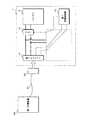
図3は、本実施の形態に係る車載充電システムの構成を示すブロック図である。本実施の形態に係る車載充電システムは、第1充電制御部10、第1インレット11、直流遮断リレー13及び充電制御ユニット20等を備えて構成されている。また充電制御ユニット20は、第2インレット12、充電方式判定部21、コンバータ22及び信号遮断リレー23等を備えて構成されている。 FIG. 3 is a block diagram showing a configuration of the in-vehicle charging system according to the present embodiment. The in-vehicle charging system according to the present embodiment includes a first
第1インレット11は、第1充電方式を採用した第1充電装置80の充電ケーブル81の先端に設けられた充電ガン82が接続される。図示は省略するが、充電ケーブル81には、例えば2本の電力供給線と、一又は複数の信号線とが含まれている。電力供給線は、充電装置80から出力された直流電圧が印加される導線である。信号線は、車両1に搭載されたバッテリ2の充電を制御するための制御信号を伝送する導線である。第1インレット11に充電ガン82が接続された場合、充電ケーブル81の2本の電力供給線は、車両1内の2本の電力供給線101,102に対して電気的に接続される。第1インレット11は2本の電力供給線101,102を介してバッテリ2に接続されるが、その途中には直流遮断リレー13が設けられている。即ち第1インレット11及びバッテリ2は、途中に直流遮断リレー13が設けられたDC+及びDC−の2つの電力供給経路にて接続されており、直流遮断リレー13の導通/遮断により第1インレット11及びバッテリ2の間の電力供給経路が導通/遮断される。 The
また第1インレット11に充電ガン82が接続された場合、充電ケーブル81の一又は複数の信号線は、車両1内の一又は複数の信号線103,104に対して電気的に接続される(図3においては簡略化して2本の信号線103,104のみを図示してある)。信号線103,104は、充電制御ユニット20内の充電方式判定部21を経て、第1充電制御部10に接続されている。また信号線103,104は途中に分岐部分が設けられ、分岐した信号線109,110は充電制御ユニット20内のコンバータ22に接続されている。これによりコンバータ22は、第1インレット11及び第1充電制御部10の間で授受される信号を監視することができ、場合によっては信号線103,104に対して信号を出力することができる。一又は複数の信号線103,104には、例えば第1充電装置80との通信を行うための通信線(CANバス)、第1インレット11に対する充電ガン82の接続検知に関する信号を伝達する信号線、又は、第1インレット11に接続された充電ガン82をロックするための制御信号を伝達する信号線等が含まれ得る。CHAdeMO方式の場合、信号線103,104には、充電開始停止1、充電開始停止2、コネクタ接続確認及び充電許可禁止等の情報を授受するためのアナログ信号を伝達する信号線が含まれる。 When the charging
充電制御ユニット20の第2インレット12は、第2充電方式を採用した第2充電装置90の充電ケーブル91の先端に設けられた充電ガン92が接続される。図示は省略するが、充電ケーブル91には、例えば2本の電力供給線と、一又は複数の信号線とが含まれている。第2インレット12に充電ガン92が接続された場合、充電ケーブル91の2本の電力供給線は、車両1内の2本の電力供給線105,106に対して電気的に接続される。2本の電力供給線105,106の一端は第2インレット12に接続され、他端は2本の電力供給線101,102の第1インレット11及び直流遮断リレー13の間の適所にそれぞれ接続されている。よって第2インレットは、2本の電力供給線105,106と、2本の電力供給線101,102とを介してバッテリ2に接続され、その途中には直流遮断リレー13が設けられて電力供給経路の導通/遮断が行われる。 The
また第2インレット12に充電ガン92が接続された場合、充電ケーブル91の一又は複数の信号線は、充電制御ユニット20内の一又は複数の信号線107,108に対して電気的に接続される。信号線107,108は、充電方式判定部21を経て、コンバータ22に接続されている。一又は複数の信号線107,108には、例えば第2充電装置90との通信を行うための通信線(CPLT)、第2インレット12に対する充電ガン92の接続検知に関する信号を伝達する信号線、又は、第2インレット12に接続された充電ガン92をロックするための制御信号を伝達する信号線等が含まれ得る。When the charging
直流遮断リレー13は、第1インレット11及びバッテリ2を接続する2つの電力供給線101,102の途中にそれぞれ設けられた2つの電磁リレーである。直流遮断リレー13の制御端子には、導通/遮断を切り替える制御信号を伝達するための信号線111,112が接続されている。直流遮断リレー13及び第1充電制御部10は、信号線111,112を介して接続されているが、その途中には信号遮断リレー23が設けられている。信号遮断リレー23は、充電制御ユニット20内に設けられており、2つの信号線111,112の途中にそれぞれ設けられた2つの電磁リレーである。信号遮断リレー23の制御端子は、信号線113,114を介してコンバータ22に接続されている。即ち、第1充電制御部10から直流遮断リレー13までの制御信号の伝達経路中に信号遮断リレー23が設けられ、この伝達経路の導通/遮断がコンバータ22により制御されている。なお直流遮断リレー13及び信号遮断リレー23は、通常は遮断状態であり、導通状態へ切り替えられる制御信号が与えられた場合にのみ導通状態となる。 The
図4は、充電制御ユニット20の充電方式判定部21及びコンバータ22の構成を示すブロック図である。充電制御ユニット20の充電方式判定部21は、第1嵌合検知部21a及び第2嵌合検知部21bを備えて構成されている。またコンバータ22は、変換部30、ロック制御部31、CPLT制御部32、CPLT観測部33、PLC通信部34、CAN通信部35及び入出力監視部36等を備えて構成されている。 FIG. 4 is a block diagram illustrating the configuration of the charging
第1嵌合検知部21aは、第1インレット11及び第1充電制御部10の間に配される一又は複数の信号線103,104のうち、充電ガン82の接続状態を示す信号を伝達する信号線に接続され、この信号の状態変化を検知することにより第1インレット11に対する充電ガン82の接続を検知する。第1インレット11には、例えば充電ガン82が接続された場合に押下される機械式のスイッチが設けられており、このスイッチの状態を示す信号が第1インレット11から第1充電制御部10へ信号線を介して伝達される。 The first
同様に、第2嵌合検知部21bは、第2インレット12及びコンバータ22の間に配される一又は複数の信号線107,108のうち、充電ガン92の接続状態を示す信号を伝達する信号線に接続され、この信号の状態変化を検知することにより第2インレット12に対する充電ガン92の接続を検知する。第2インレット12には、例えば充電ガン92が接続された場合に押下される機械式のスイッチが設けられており、このスイッチの状態を示す信号が第2インレット12からコンバータ22へ信号線を介して伝達される。 Similarly, the second
充電方式判定部21は、第1嵌合検知部21aの検知結果及び第2嵌合検知部21bの検知結果に基づいて、第1充電方式による充電を行うか又は第2充電方式による充電を行うかを判定し、判定結果をコンバータ22の変換部30へ通知する。充電方式判定部21は、第1インレット11に対する充電ガン82の接続を第1嵌合検知部21aが検知した場合、第1充電方式による充電を行う旨を変換部30へ通知する。充電方式判定部21は、第2インレット12に対する充電ガン92の接続を第2嵌合検知部21bが検知した場合、第2充電方式による充電を行う旨を変換部30へ通知する。また、第1インレット11に充電ガン82が接続されておらず、且つ、第2インレット12に充電ガン92が接続されていない場合、充電方式判定部21は、充電を行わない旨を変換部30へ通知する。The charging
コンバータ22のロック制御部31は、第2インレット12に充電ガン92が接続された後、第2充電装置90からバッテリ2への充電が行われている状態において充電ガン92が第2インレット12から取り外されることを防止するために、充電ガン92を第2インレット12に接続された状態でロックする制御を行う。このため第2インレット12には、例えばアクチュエータなどを利用したロック機構が備えられている。第2インレット12及びコンバータ22の間に設けられる信号線107,108には、このアクチュエータの動作を制御するための信号線が含まれており、この信号線はロック制御部31に接続されている。ロック制御部31は、変換部30から与えられる命令に応じて、第2インレット12のロック機構にロック又はアンロックを行わせる制御信号を出力する。なお第1インレット11にも同様のロック機構が備えられており、このロック機構の制御は第1充電制御部10により行われる。After the charging
また第2インレット12及びコンバータ22の間に設けられる信号線107,108には、第2充電装置90との間で授受されるCPLT信号を伝達する信号線が含まれている。このCPLTの信号線は、コンバータ22のCPLT制御部32、CPLT観測部33及びPLC通信部34に接続されている。CPLT信号は、第2充電方式にて車両1及び第2充電装置90の間で授受される制御信号であり、例えば1kHzの矩形波信号である。CPLT制御部32は、CPLT信号の出力及び停止を制御する。CPLT観測部33は、CPLT信号の電位の測定及び電位の変化の検出等を行う。CPLT制御部32及びCPLT観測部33は、基準電位に対する矩形波信号の電位、矩形波信号の出力の有無、及び、デューティ比等により、第2充電装置90との間で、第2充電装置90及び車両1の接続確認、充電の可否及び充電状態等の充電に関する情報を授受する。例えばCPLT観測部33は、デューティ比5%のCPLT信号を検出することによって、DC充電を行うことができる充電スタンドに接続されたことを検知することができる。PLC通信部34は、CPLT信号よりも高周波の信号、例えば2〜30MHzの信号を、CPLT信号に重畳することにより第2充電装置90との間で通信を行う。PLC通信部34は、第2充電装置90との間で充電に関する情報を送受信する。 The signal lines 107 and 108 provided between the
このように第2充電方式では、第2充電装置90及び車両1の間でCPLT信号による情報の授受と、CPLT信号に重畳した信号による情報の授受とが行われる。 As described above, in the second charging method, information exchange using the CPLT signal and information exchange using the signal superimposed on the CPLT signal are performed between the
これに対して第1充電方式では、第1充電装置80及び車両1の間で、CANのプロトコルに従った通信が行われる。このため第1充電装置80の充電ケーブル81にはCANの通信線(CANバス)が含まれており、第1インレット11及び第1充電制御部10の間に設けられる信号線103,104にはCANバスが含まれている。なおCANのプロトコルでは差動信号が授受されるため、実際のCANバスは2本の通信線で構成されるが、図4においてCANバスは1本の線として略して記載している。In contrast, in the first charging method, communication according to the CAN protocol is performed between the
コンバータ22のCAN通信部35は、第1インレット11及び第1充電制御部10の間に設けられるCANバスに接続されており、CANプロトコルに従った通信により第1充電制御部10との通信を行うことができる。CAN通信部35は、変換部30から与えられた送信情報を電気信号に変換してCANバスへ出力することにより情報の送信を行うと共に、CANバスの電位をサンプリングして得られた受信情報を変換部30へ与える。The
コンバータ22の入出力監視部36は、第1インレット11及び第1充電制御部10の間に設けられるCANバス以外の信号線、例えばCHAdeMO方式のアナログ信号線を介して授受される信号を監視すると共に、必要に応じてこれらの信号線に信号を出力する。即ち入出力監視部36は、第2充電方式での充電を行う際に、充電開始停止1、充電開始停止2、コネクタ接続確認及び充電許可禁止等のアナログ信号線に対する信号の出力及び監視を行うことによって、第1充電制御部10との情報交換を行う。The input /
このように第2充電方式では、コンバータ22は第1充電制御部10との間で、CANバスを介した通信をCAN通信部35にて行うと共に、アナログ信号線を介した通信を入出力監視部36にて行う。これに対して第1充電方式では、第1充電装置80と第1充電制御部10との間で直接的にCANバスを介した通信及びアナログ信号線を介した通信が行われる。 As described above, in the second charging method, the
コンバータ22の変換部30は、コンバータ22内の各部から与えられる情報を取得すると共に、各部の動作を制御することによって、第1充電方式に従った通信と、第2充電方式に従った通信との変換を行う。変換部30は、CPLT制御部32、CPLT観測部33及びPLC通信部34により、第2インレット12に充電ケーブル91を介して接続された第2充電装置90との間で、第2充電方式に従った通信を行うことができる。また変換部30は、CAN通信部35及び入出力監視部36により、第1充電制御部10との間で第1充電方式に従った通信を行うことができる。よって変換部30は、第2充電方式に従った通信にて第2充電装置90から受信した情報を、第1充電方式の通信に適した情報に変換して第1充電制御部10へ送信すると共に、第1充電方式に従った通信にて第1充電制御部10から受信した情報を、第2充電方式に適した情報に変換して第2充電装置90へ送信することができる。
また変換部30は、信号遮断リレー23の導通/遮断を切り替える制御を行う。充電方式判定部21から第1充電方式にて充電を行う旨の通知が与えられた場合、変換部30は、信号遮断リレー23を導通状態とする。これにより直流遮断リレー13は、第1充電制御部10が出力する制御信号に応じて導通/遮断の切り替えが行われる。なおこのときに交換部30は、CPLT制御部32、CPLT観測部33及びPLC通信部34によるCPLTの通信線を介した通信を行わず、CAN通信部35による第1充電制御部10との通信を行わない。この状態において車両1のバッテリ2の充電は、第1充電制御部10により制御され、第1充電方式に従って第1充電装置80からバッテリ2への充電が行われる。The
これに対して、充電方式判定部21から第2充電方式にて充電を行う旨の通知が与えられた場合、変換部30は、まず信号遮断リレー23を遮断状態とする。その後、変換部30は、上述のように第2充電装置90及び第1充電制御部10の間の通信を中継する処理を行い、この処理過程において所定のタイミングで信号遮断リレー23を導通状態とする。なおこれより前のタイミングで第1充電制御部10は直流遮断リレー13を導通状態とする信号を出力しているが、信号遮断リレー23が遮断状態であるためこの信号が直流遮断リレー13に伝達されず、直流遮断リレー13は遮断状態となっている。変換部30が信号遮断リレー23を導通させることにより第1充電制御部10の出力信号が直流遮断リレー13まで伝達され、直流遮断リレー13が導通状態となる。 On the other hand, when the notification that the charging is performed by the second charging method is given from the charging
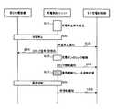
図5は、第2充電方式にて充電を行う際に充電制御ユニット20が行う中継処理を説明するためのシーケンス図である。第2充電装置90の充電ガン92が第2インレット12に接続されたことを第2嵌合検知部21bが検知し、充電方式判定部21が第2充電方式で充電を行うと判定することにより(ステップS1)、充電制御ユニット20による中継処理が開始される。CPLT観測部33がデューティ比5%のCPLT信号を検出した場合(ステップS2)、第2充電装置90及び充電制御ユニット20は、充電ケーブル91を介して制御信号の送受信を行い、通信セッションを初期化し、通信を確立する(ステップS3)。なおこのときのCPLT信号の電圧レベルは9Vであり、いわゆる状態Bにある。また、第2充電装置90及び充電制御ユニット20は、ユーザ認証等の各種処理を行い(ステップS4)、バッテリ2の充電に必要な各種パラメータの交換を行う(ステップS5)。 FIG. 5 is a sequence diagram for explaining a relay process performed by the charging
次いで、充電制御ユニット20は、入出力監視部36にてアナログ信号線に含まれるコネクタ接続確認の信号をオン状態とすることで、充電装置との接続が行われた旨を第1充電制御部10へ通知する(ステップS6)。また充電制御ユニット20は、入出力監視部36にてアナログ信号線に含まれる充電開始停止1の信号をオン状態とする(ステップS7)。充電開始停止1の信号がオン状態となったことを検出すると、第1充電制御部10はCAN通信を開始する。充電制御ユニット20のCAN通信部35は、第1充電制御部10との間でCAN通信を行い、充電パラメータの交換を行う(ステップS8)。第2充電装置90の充電パラメータが車両1のバッテリ2に適合している場合、第1充電制御部10は、アナログ信号線の充電許可禁止の信号により、充電制御ユニット20へ充電許可の通知を行う(ステップS9)。 Next, the charging
充電許可の通知を受けた充電制御ユニット20は、ロック制御部31にて第2インレット12に接続された充電ガン92をロックする(ステップS10)。充電制御ユニット20は、充電ガン92がロックされたことを第1充電制御部10へ通知する(ステップS11)。 The
次いで、充電制御ユニット20は、CPLT制御部32にてCPLT信号を状態Cに制御する(ステップS12)。状態Cは、CPLT信号の電圧レベルが6Vの状態であり、車両1側の充電の準備が完了した状態を示している。 Next, the charging
次いで、充電制御ユニット20は、信号遮断リレー23を遮断状態とし(ステップS13)、第2充電装置90との間で安全確認を行い(ステップS14)、プリチャージを行う(ステップS15)。安全確認及びプリチャージの結果に問題が無いことが確認された場合、充電制御ユニット20は、入出力監視部36にてアナログ信号線に含まれる充電開始停止2の信号をオン状態とする(ステップS16)。その後、充電制御ユニット20は、信号遮断リレー23を導通状態とする(ステップS17)。Next, the charging
そして、充電制御ユニット20は、第2充電装置90との間で制御信号を送受信し、第2充電装置90にバッテリ2の充電を開始させる(ステップS18)。充電中、充電制御ユニット20は、第1充電制御部10からの充電電流の指示をCAN通信部35にて受信する(ステップS19)。次いで、充電制御ユニット20は、PLC通信部34にて、受信した充電電流の指示を第2充電装置90へ送信し、第2充電装置90から送信された充電電圧、電流等の通知を受信し(ステップS20)、受信した充電電圧、電流等の情報をCAN通信部35にて第1充電制御部10へ送信する(ステップS21)。第1充電制御部10、充電制御ユニット20及び第2充電装置90は、ステップS19〜ステップS21の処理を繰り返し実行することにより、充電制御を行う。 Then, the charging
図6は、第2充電方式による充電を停止する際に充電制御ユニット20が行う中継処理を説明するためのシーケンス図である。充電制御ユニット20は、充電中、充電停止条件を監視している。例えば、第1充電制御部10から送信される充電停止要求をCAN通信部35にて監視しており、第1充電制御部10から充電停止要求があった場合、充電停止条件が成立したと判定する。充電制御ユニット20は、充電停止条件が成立した場合(ステップS31)、PLC通信部34にて充電停止を第2充電装置90へ通知し、第2充電装置90は充電停止の通知を受けて、直流電圧の供給を停止させる(ステップS32)。 FIG. 6 is a sequence diagram for explaining a relay process performed by the charging
次いで、充電制御ユニット20は、充電の停止を第1充電制御部10へ通知し(ステップS33)、CPLT制御部32にて、CPLT信号を状態Bに制御する(ステップS34)。そして、充電制御ユニット20は、ロック制御部31にて第2インレット12に対する充電ガン92のロックを解除し(ステップS35)、ロックを解除したことを第1充電制御部10へ通知する(ステップS36)。 Next, the charging
次いで、充電制御ユニット20は、信号遮断リレー23を遮断状態とし(ステップS37)、第2充電装置90との間で通信切断に係る処理を実行し(ステップS38)、第2インレット12に充電ガン92が未接続であることを第1充電制御部10へ通知する(ステップS39)。 Next, the charging
以上の処理手順に従って車両1のバッテリ2の充電が行われる。次に、異常電流の発生を防ぐための信号遮断リレー23の導通/遮断の切り替えに係る処理手順の要部を説明する。図7は、充電制御ユニット20が行う信号遮断リレー23の制御処理の手順を示すフローチャートである。なお本処理において充電制御ユニット20は、第2充電装置90から供給される直流電圧(以下、充電電圧という)と、バッテリ2の端子間の電圧(以下、バッテリ電圧という)とを取得する必要があり。図1〜図3において図示は省略したが、本実施の形態において車両1には、充電電圧を検出する電圧計と、バッテリ電圧を検出する電圧計とが備えられている。これらの電圧計が検出した電圧値は、充電制御ユニット20及び第1充電制御部10等へ与えられる。 The battery 2 of the
充電制御ユニット20の変換部30は、充電方式判定部21により第1充電方式で充電を行うか否かを判定する(ステップS100)。第1充電方式で充電を行う場合(S100:YES)、変換部30は、信号遮断リレー23を導通させる信号を出力し、信号遮断リレー23を導通状態に切り替えて(ステップS106)、処理を終了する。第2充電方式で充電を行う場合(S100:NO)、変換部30は、所定のタイミングで信号遮断リレー23を遮断する信号を出力し、信号遮断リレー23を遮断状態へ切り替える(ステップS101)。つまり、変換部30は、信号遮断リレー23を遮断状態に制御することによって、第1充電制御部10の制御に拘わらず、直流遮断リレー13が導通状態とならないようにし、第2充電装置90及びバッテリ2間の通電を制限する。なお、前記所定のタイミングは、第2充電装置90から直流電圧が供給され、直流遮断リレー13を閉じる制御が第1充電制御部10により行われる前段階のタイミングであれば、そのタイミングは特に限定されるものでは無い。 The
次いで、変換部30は、電圧計にて検出された充電電圧を取得し(ステップS102)、検出されたバッテリ電圧を取得する(ステップS103)。そして、変換部30は、ステップS102及びステップS103にて取得した直流電圧及びバッテリ電圧の電圧差が閾値未満であるか否かを判定する(ステップS104)。充電電圧及びバッテリ電圧の電圧差が閾値以上であると判定した場合(ステップS104:NO)、変換部30は、第2充電装置90が供給する直流電圧を変更させるための情報をPLC通信部34にて第2充電装置90へ送信し(ステップS105)、処理をステップS102へ戻す。第2充電装置90は、車両1から送信された情報を受信し、受信した情報に従って、直流電圧の電圧を変更する。Next, the
充電電圧及びバッテリ電圧の電圧差が閾値未満であると判定した場合(ステップS104:YES)、変換部30は、信号遮断リレー23を導通状態とする信号を出力し、信号遮断リレー23を導通状態に切り替え(ステップS106)、処理を終える。つまり、変換部30は、信号遮断リレー23を通電状態に制御することによって、第2充電装置90及びバッテリ2間の通電の制限を解除する。 When it is determined that the voltage difference between the charging voltage and the battery voltage is less than the threshold value (step S104: YES), the
図8は、本実施の形態に係る車両1に設けられる充電口の構成を示す模式図である。本実施の形態に係る車両1は、充電制御ユニット20を装着することによって、第1充電方式及び第2充電方式の2種の充電方式にてバッテリ2の充電を行うことができる。充電制御ユニット20を装着した状態において、車両1の充電口には、第1充電方式に対応した充電ガン82を接続するための第1インレット11と、第2充電方式に対応した充電ガン92を接続するための第2インレット12とが並べて設けられる。 FIG. 8 is a schematic diagram showing a configuration of a charging port provided in
図示の例では、車両1の充電口は、水平方向に長い略長方形の開口部を有する凹所として設けられる。第1インレット11及び第2インレット12は、この凹所の底部分に、長手方向へ並べて設けられている。また車両1の充電口は、開口部の略半分を覆い隠すことができるスライドカバー3が設けられている。スライドカバー3は、開口部の長手方向へ自在にスライドさせることができる。スライドカバー3は、長手方向の端部までスライドされることにより、充電口内に設けられた第1インレット11及び第2インレット12のいずれか一方を覆い隠し、他方を露出させる。 In the illustrated example, the charging port of the
よって車両1のユーザは、利用する充電装置の充電ガンの形状などに応じてスライドカバー3をスライドさせて、第1インレット11及び第2インレット12のいずれか一方を露出させ、露出させたインレットへ充電ガンを接続することができる。このときに使用されないインレットは、スライドカバー3により覆い隠されて、使用が禁止される。 Therefore, the user of the
以上の構成の本実施の形態に係る車載充電システムは、第1充電方式による充電を行うための充電ケーブル81の充電ガン82が接続される第1インレット11と、第2充電方式による充電を行うための充電ケーブル91の充電ガン92が接続される第2インレットとを車両1に設けている。これにより第1充電方式又は第2充電方式のいずれを採用した充電装置であっても、充電ケーブル81,91を車両1の第1インレット11又は第2インレット12に接続してバッテリ2への電力を供給することが可能となる。 The in-vehicle charging system according to the present embodiment having the above-described configuration performs charging by the
本実施の形態に係る車載充電システムは、第1充電方式によりバッテリ2への充電を制御する第1充電制御部10を備える。第1充電制御部10は、第1インレット11に接続された充電ケーブル81を介して第1充電装置80との通信を行い、第1インレット11からバッテリ2への電力供給経路に設けられた直流遮断リレー13を導通させることによってバッテリ2の充電を行う。これにより、第1充電方式を採用した第1充電装置80を利用して車両1のバッテリ2を充電することができる。 The in-vehicle charging system according to the present embodiment includes a first
本実施の形態に係る車載充電システムは、第2充電方式にて充電を行うべきと判定した場合、第2充電装置90と第1充電制御部10との通信を充電制御ユニット20が中継する。充電制御ユニット20は、第1充電方式に従った通信にて送受信する情報と、第2充電方式に従った通信にて送受信する情報とを相互に変換する処理を行う。更に車載充電システムは、第1充電方式と第2充電方式とでは直流遮断リレー13を導通させるタイミングが異なることから、第2充電方式で充電を行う場合には、第1充電制御部10が直流遮断リレー13を導通させるタイミングに対して、実際に直流遮断リレー13を導通させるタイミングを遅らせる制御を行う。これにより、本来は第1充電方式に従った充電制御を行う第1充電制御部10は、充電制御ユニット20を介して第2充電方式に従う第2充電装置90との通信を行うことができ、第2充電方式に適したタイミングで直流遮断リレー13を導通させてバッテリ2への電力供給を開始することが可能となる。 In the in-vehicle charging system according to the present embodiment, when it is determined that charging should be performed by the second charging method, the charging
よって本実施の形態に係る車載充電システムは、第1充電方式及び第2充電方式のいずれを採用した充電装置であっても、車両1のバッテリ2の充電を行うことができる。 Therefore, the in-vehicle charging system according to the present embodiment can charge the battery 2 of the
また本実施の形態に係る車載充電システムでは、導通/遮断を切り替える制御信号が第1充電制御部10から直流遮断リレー13に対して与えられ、第1充電制御部10から直流遮断リレー13までの間には制御信号を伝達するための制御信号伝達経路が信号線111,112として設けられる。本実施の形態においては、この制御信号伝達経路の導通/遮断を切り替える信号遮断リレー23を設け、この信号遮断リレー23の導通/遮断を制御することにより、充電制御ユニット20がバッテリ2への電力供給開始のタイミングを遅らせる制御を行う。即ち、第1充電制御部10が直流遮断リレー13を導通させる制御信号を出力しても、信号遮断リレー23を遮断状態としておくことで、直流遮断リレー13を導通させずに遮断状態で維持することができる。 Further, in the in-vehicle charging system according to the present embodiment, a control signal for switching between conduction / cutoff is given from the first
また本実施の形態に係る車載充電システムでは、充電方式判定部21が第1充電方式で充電を行うべきと判定した場合、信号遮断リレー23を導通状態で維持する。これにより直流遮断リレー13は第1充電制御部10から与えられる制御信号に応じて導通/遮断の切り替えが行われ、第1充電制御部10による第1充電方式に従ったバッテリ2の充電を行うことができる。 Further, in the in-vehicle charging system according to the present embodiment, when the charging
これに対して第2充電方式で充電を行うべきと充電方式判定部21判定した場合、充電制御ユニット20は、信号遮断リレー23を遮断状態とした後、第1充電制御部10が直流遮断リレー13を導通状態とする信号を出力するタイミングより遅いタイミングで、信号遮断リレー23を導通状態とする。これにより信号遮断リレー23が導通状態とされた際に、第1充電制御部10からの制御信号が直流遮断リレー13へ伝達され、直流遮断リレー13が導通状態となる。よって第2充電方式で充電を行う場合には、第1充電方式の場合よりも遅いタイミングで直流遮断リレー13を導通させることが可能となり、第2充電方式に適したタイミングでバッテリ2への電力供給を開始することができる。On the other hand, when the charging
また本実施の形態に係る車載充電システムでは、第1インレット11に対する充電ケーブル81の充電ガン82の接続検知を第1嵌合検知部21aにて行うと共に、第2インレット12に対する充電ケーブル91の充電ガン92の接続検知を第2嵌合検知部21bにて行い、これらの検知結果に基づいて第1充電方式又は第2充電方式のいずれの方式で充電を行うべきかを充電方式判定部21が判定する。これにより車載充電システムは、容易且つ確実に充電方式を選択してバッテリ2の充電を行うことができる。 In the in-vehicle charging system according to the present embodiment, the connection detection of the charging
また本実施の形態に係る車載充電システムでは、第1インレット11又は第2インレット12のいずれか一方に充電ケーブル81,91の充電ガン82,92が接続された場合に、他方への接続を禁止する。例えば車両1の充電口に第1インレット11及び第2インレット12が並べて配置されている場合に、第1インレット11又は第2インレット12のいずれか一方を覆い隠す位置へスライドするスライドカバー3などを設けることで接続禁止を実現することができる。これにより、第1インレット11及び第2インレット12の両方にそれぞれ充電ケーブル81,91が接続されることを防止できる。なお接続禁止をスライドカバー3にて行う構成は一例であり、これ以外の構成を採用してもよい。Further, in the in-vehicle charging system according to the present embodiment, when charging
また本実施の形態に係る車載充電システムでは、第1充電方式としてCHAdeMO方式を採用し、第2充電方式としてCCS方式を採用することができる。CCS方式は、CHAdeMO方式より直流遮断リレー13を導通させるタイミングが遅いため、上述の構成に好適である。ただし第1充電方式又は第2充電方式として、CHAdeMO方式又はCCS方式以外の充電方式を採用してもよい。 In the in-vehicle charging system according to the present embodiment, the CHAdeMO method can be adopted as the first charging method, and the CCS method can be adopted as the second charging method. The CCS method is suitable for the above-described configuration because the timing for turning on the
また本実施の形態に係る車載充電システムでは、第2インレット12、充電方式判定部21、コンバータ22及び信号遮断リレー23を備える充電制御ユニット20を、車両1に対して着脱可能な構成とする。これにより、第1充電方式を採用した車両1に対して、第2充電方式による充電を行う機能を容易に追加又は削除することが可能となる。 In the in-vehicle charging system according to the present embodiment, the charging
<実施の形態2>
図9は、実施の形態2に係る車載充電システムの構成を示すブロック図である。実施の形態2に係る車載充電システムは、第1充電制御部10から直流遮断リレー13までの制御信号伝達経路に信号遮断リレー23を備えず、直流遮断リレー13は第1充電制御部10の制御に応じてのみ導通/遮断の切り替えが行われる。このため実施の形態2に係る充電制御ユニット202のコンバータ22は、信号遮断リレー23の導通/遮断を制御する機能を有していない。<Embodiment 2>
FIG. 9 is a block diagram illustrating a configuration of the in-vehicle charging system according to the second embodiment. The in-vehicle charging system according to Embodiment 2 does not include the
実施の形態2に係る車載充電システムは、第1インレット11からバッテリ2までの電力供給経路中に逆流防止ダイオード250が設けられている。逆流防止ダイオード250は、2本の電力供給線101,102のうち、DC+に相当する電力供給線101に設けられている。逆流防止ダイオード250は、第1インレット11からバッテリ2へ順接続されており、第1インレット11からバッテリ2へ電流を流すが、バッテリ2から第1インレット11への電流は流さない。 In the in-vehicle charging system according to Embodiment 2, a
よって実施の形態2に係る車載充電システムでは、実施の形態1に係る信号遮断リレー23により直流遮断リレー13の導通を遅らせる制御を行う構成に代えて、第1インレット11及び第2インレット12からバッテリ2への電力供給経路中に逆流防止ダイオード250を設けた構成である。これにより第2充電方式で充電を行う際に、第2充電方式でのタイミングより早いタイミングで直流遮断リレー13が導通された場合であっても、バッテリ2から第2充電装置90へ電流が逆流することを防止できる。 Therefore, in the in-vehicle charging system according to the second embodiment, instead of the configuration in which the signal cut-
1 車両
2 バッテリ
3 スライドカバー(接続禁止部)
10 第1充電制御部(充電制御部)
11 第1インレット(第1接続部)
12 第2インレット(第2接続部)
13 直流遮断リレー(第1リレー)
20 充電制御ユニット
21 充電方式判定部
21a 第1嵌合検知部(第1接続検知部)
21b 第2嵌合検知部(第2接続検知部)
22 コンバータ(中継部、遅延制御部)
23 信号遮断リレー(第2リレー)
30 変換部
31 ロック制御部
32 CPLT制御部
33 CPLT観測部
34 PLC通信部
35 CAN通信部
36 入出力監視部
80 第1充電装置
81 充電ケーブル
82 充電ガン
90 第2充電装置
91 充電ケーブル
92 充電ガン
202 充電制御ユニット
250 逆流防止ダイオード(逆流防止部)1 Vehicle 2
10 1st charge control part (charge control part)
11 1st inlet (1st connection part)
12 2nd inlet (2nd connection part)
13 DC cutoff relay (first relay)
20
21b 2nd fitting detection part (2nd connection detection part)
22 Converter (relay unit, delay control unit)
23 Signal interruption relay (second relay)
30
Claims (4)
Translated fromJapanese前記第1接続部及び前記第2接続部から前記バッテリへの電力供給経路に設けられ、該電力供給経路の導通又は遮断を切り替える第1リレーと、
前記第1接続部に接続された充電ケーブルを介して前記第1充電装置との通信を行い、前記第1充電方式に従い前記第1リレーを導通させて前記バッテリの充電を行う充電制御部と、
前記第1充電方式又は前記第2充電方式のいずれの方式で前記バッテリの充電を行うべきかを判定する充電方式判定部と、
前記第2充電方式で充電を行うべきと前記充電方式判定部が判定した場合に、前記第2接続部に接続された充電ケーブルを介して前記第2充電装置との通信を行うと共に、前記充電制御部との通信を行い、前記第2充電装置及び前記充電制御部の間の通信を中継する中継部と、
前記第2充電方式で充電を行うべきと前記充電方式判定部が判定した場合に、前記充電制御部による前記第1リレーの導通を遅延させる制御を行う遅延制御部と、
前記充電制御部から前記第1リレーまでの制御信号伝達経路に設けられ、該制御信号伝達経路の導通又は遮断を切り替える第2リレーと
を備え、
前記遅延制御部は、
前記充電方式判定部が前記第1充電方式で充電を行うべきと判定した場合に、前記第2リレーを導通状態で維持し、
前記充電方式判定部が前記第2充電方式で充電を行うべきと判定した場合に、前記第2リレーを遮断状態とした後、前記充電制御部が前記第1リレーを導通状態とする信号を出力するタイミングより遅いタイミングで前記第2リレーを導通状態に切り替えること
を特徴とする車載充電システム。A first connecting part to which a charging cable of a first charging device that performs charging by the first charging method is connected and a second connecting part to which a charging cable of a second charging device that performs charging by the second charging method are connected are provided. An on-vehicle charging system that is mounted on a vehicle and charges the battery of the vehicle with electric power supplied from the first charging device or the second charging device,
A first relay provided in a power supply path from the first connection part and the second connection part to the battery, and switching between conduction and interruption of the power supply path;
A charge control unit that communicates with the first charging device via a charging cable connected to the first connection unit, and conducts the first relay according to the first charging method to charge the battery;
A charging method determination unit that determines whether the battery should be charged in any of the first charging method or the second charging method;
When the charging method determination unit determines that charging should be performed by the second charging method, the charging method is communicated with the second charging device via a charging cable connected to the second connection unit, and the charging is performed. A relay unit that communicates with the control unit and relays communication between the second charging device and the charging control unit;
A delay control unit that performs control to delay conduction of the first relay by the charge control unit when the charging method determination unit determines that charging should be performed by the second charging method;
A control signal transmission path from the charge control unit to the first relay, and a second relay that switches between conduction and interruption of the control signal transmission path,
The delay control unit
When the charging method determination unit determines that charging should be performed in the first charging method, the second relay is maintained in a conductive state;
When the charging method determination unit determines that charging should be performed by the second charging method, the charging control unit outputs a signal for setting the first relay to a conductive state after the second relay is turned off. The vehicle-mounted charging system, wherein the second relay is switched to a conductive state at a timing later than the timing to perform.
前記第2接続部に対する充電ケーブルの接続を検知する第2接続検知部と
を備え、
前記充電方式判定部は、前記第1接続検知部の検知結果及び前記第2接続検知部の検知結果に基づいて判定を行うこと
を特徴とする請求項1に記載の車載充電システム。A first connection detection unit for detecting connection of a charging cable to the first connection unit;
A second connection detection unit that detects connection of a charging cable to the second connection unit;
The in-vehicle charging system according to claim1, wherein the charging method determination unit makes a determination based on a detection result of the first connection detection unit and a detection result of the second connection detection unit.
を特徴とする請求項1又は請求項2に記載の車載充電システム。When the first connecting portion and the charging cable to one of the second connecting portion are connected, according to claim 1or claim, characterized in that it comprises a connection prohibition portion that prohibits connection of the charging cable to the other The in-vehicle charging system according to Item2 .
前記第2充電方式は、CCS(Combined Charging System)方式であること
を特徴とする請求項1乃至請求項3のいずれか1つに記載の車載充電システム。The first charging method is a CHAdeMO method,
The in-vehicle charging system according to any one of claims 1 to3 , wherein the second charging method is a CCS (Combined Charging System) method.
Priority Applications (4)
| Application Number | Priority Date | Filing Date | Title |
|---|---|---|---|
| JP2015155424AJP6569122B2 (en) | 2015-08-05 | 2015-08-05 | In-vehicle charging system |
| PCT/JP2016/071889WO2017022572A1 (en) | 2015-08-05 | 2016-07-26 | Vehicle-mounted charging system |
| US15/748,273US10471836B2 (en) | 2015-08-05 | 2016-07-26 | Vehicle-mounted charging system |
| CN201680042120.5ACN107852020B (en) | 2015-08-05 | 2016-07-26 | Vehicle-mounted charging system |
Applications Claiming Priority (1)
| Application Number | Priority Date | Filing Date | Title |
|---|---|---|---|
| JP2015155424AJP6569122B2 (en) | 2015-08-05 | 2015-08-05 | In-vehicle charging system |
Publications (3)
| Publication Number | Publication Date |
|---|---|
| JP2017034938A JP2017034938A (en) | 2017-02-09 |
| JP2017034938A5 JP2017034938A5 (en) | 2018-03-01 |
| JP6569122B2true JP6569122B2 (en) | 2019-09-04 |
Family
ID=57943896
Family Applications (1)
| Application Number | Title | Priority Date | Filing Date |
|---|---|---|---|
| JP2015155424AActiveJP6569122B2 (en) | 2015-08-05 | 2015-08-05 | In-vehicle charging system |
Country Status (4)
| Country | Link |
|---|---|
| US (1) | US10471836B2 (en) |
| JP (1) | JP6569122B2 (en) |
| CN (1) | CN107852020B (en) |
| WO (1) | WO2017022572A1 (en) |
Families Citing this family (29)
| Publication number | Priority date | Publication date | Assignee | Title |
|---|---|---|---|---|
| DE102016211335B4 (en)* | 2016-06-24 | 2025-01-02 | Volkswagen Aktiengesellschaft | Method, adapter, additional control unit and charging system for the electrical charging of electric vehicles |
| JP6541713B2 (en)* | 2017-04-28 | 2019-07-10 | 本田技研工業株式会社 | Vehicle power supply |
| KR102500690B1 (en)* | 2017-09-18 | 2023-02-17 | 삼성전자주식회사 | Battery status based charging control method and appratus thereof |
| DE102018102714A1 (en)* | 2018-02-07 | 2019-08-08 | Man Truck & Bus Ag | Device for charging an electrical energy store of an electric motor vehicle, in particular electric utility vehicle |
| JP7020187B2 (en)* | 2018-03-02 | 2022-02-16 | トヨタ自動車株式会社 | In-vehicle power supply |
| CN109130909B (en)* | 2018-07-27 | 2023-11-10 | 广州万城万充新能源科技有限公司 | Intelligent connection device for conducting and charging electric automobile |
| CN109278576A (en)* | 2018-11-08 | 2019-01-29 | 东软睿驰汽车技术(沈阳)有限公司 | A kind of charging management method of electric vehicle, system and electric vehicle |
| JP7249164B2 (en)* | 2019-02-05 | 2023-03-30 | 株式会社Subaru | vehicle |
| FR3094150B1 (en)* | 2019-03-18 | 2021-02-19 | Renault Sas | Method for controlling electromagnetic relays of an electric or hybrid motor vehicle |
| KR102699009B1 (en)* | 2019-04-18 | 2024-08-26 | 현대자동차주식회사 | Battery to vehicle charging system |
| CN109927589B (en)* | 2019-04-18 | 2024-09-03 | 珠海广通汽车有限公司 | Storage battery power supplementing method and device and automobile |
| US11772504B2 (en)* | 2019-08-22 | 2023-10-03 | Ioan Sasu | Fast rechargeable battery assembly and recharging equipment |
| WO2021073977A1 (en) | 2019-10-15 | 2021-04-22 | Vitesco Technologies GmbH | Vehicle on-board electrical system |
| DE102019007347B4 (en)* | 2019-10-21 | 2021-12-16 | Vitesco Technologies GmbH | Vehicle electrical system |
| CN111775734A (en)* | 2020-07-13 | 2020-10-16 | 东风汽车股份有限公司 | Adaptive American standard charging control system for pure electric vehicle and control method thereof |
| CN113991762B (en)* | 2020-07-27 | 2025-09-23 | 华为技术有限公司 | Charging device, electronic device, charging system and charging method |
| JP7399831B2 (en)* | 2020-09-11 | 2023-12-18 | 株式会社日立建機ティエラ | electric construction machinery |
| US11590850B2 (en) | 2021-02-02 | 2023-02-28 | Toyota Motor Engineering & Manufacturing North America, Inc. | Systems and methods with dual function coil providing in-vehicle wireless power |
| BR112023018849A2 (en)* | 2021-03-19 | 2023-10-10 | Changchun Jetty Automotive Tech Co Ltd | CHARGING CONTROL PILOT CIRCUIT AND CHARGING SOCKET |
| CN114179643B (en)* | 2021-10-29 | 2024-02-09 | 深圳市科华恒盛科技有限公司 | Bidirectional charging pile |
| EP4432509A4 (en)* | 2021-11-08 | 2025-04-02 | Nissan Motor Co., Ltd. | CHARGING/DISCHARGE CONTROL METHOD AND CHARGING/DISCHARGE CONTROL DEVICE |
| US11605964B1 (en)* | 2022-03-07 | 2023-03-14 | Beta Air, Llc | Charging connector control system and method for charging an electric vehicle |
| JP2023151963A (en)* | 2022-04-01 | 2023-10-16 | 株式会社Subaru | vehicle |
| JP7652130B2 (en) | 2022-04-18 | 2025-03-27 | トヨタ自動車株式会社 | server |
| CN114906000A (en)* | 2022-06-19 | 2022-08-16 | 上海阪辉新能源科技有限公司 | Control device for charging system |
| DE102022121235A1 (en)* | 2022-08-23 | 2024-02-29 | Man Truck & Bus Se | Vehicle charging communication device for establishing a charging communication connection |
| JP2024034241A (en)* | 2022-08-31 | 2024-03-13 | 株式会社小松製作所 | Charging control system, work machine, and charging control method |
| KR102790573B1 (en)* | 2023-03-15 | 2025-04-08 | 유에이티(주) | Emergency Counter Measure System against Li-Battery Pack Fire of Battery Electric Vehicle |
| CN118636733B (en)* | 2024-08-15 | 2024-11-19 | 成都赛力斯科技有限公司 | Vehicle charging method, electronic device, and storage medium |
Family Cites Families (77)
| Publication number | Priority date | Publication date | Assignee | Title |
|---|---|---|---|---|
| JP3554057B2 (en)* | 1995-02-06 | 2004-08-11 | 本田技研工業株式会社 | Battery charging control device for electric vehicles |
| JP3484251B2 (en)* | 1995-02-06 | 2004-01-06 | 本田技研工業株式会社 | Battery charging control device for electric vehicles |
| JPH09163510A (en)* | 1995-12-05 | 1997-06-20 | Suzuki Motor Corp | Electric vehicle charging control device |
| US5765656A (en)* | 1996-01-18 | 1998-06-16 | Weaver; Winstead B. | Hybrid electric motor vehicle drive |
| JPH11135159A (en)* | 1997-10-28 | 1999-05-21 | Japan Storage Battery Co Ltd | Detecting method of remaining capacity of secondary battery and its device |
| WO1999026330A2 (en)* | 1997-11-17 | 1999-05-27 | Lifestyle Technologies | Universal power supply |
| JP4341712B2 (en)* | 2007-09-10 | 2009-10-07 | トヨタ自動車株式会社 | Charge control device and charge control method for power storage mechanism |
| CN101515657A (en)* | 2008-02-22 | 2009-08-26 | 中信国安盟固利新能源科技有限公司 | Battery pack automatic maintenance device |
| JP5259220B2 (en)* | 2008-03-25 | 2013-08-07 | 富士重工業株式会社 | Electric car |
| JP4561878B2 (en)* | 2008-06-05 | 2010-10-13 | トヨタ自動車株式会社 | Vehicle equipped with power storage device and charging cable |
| WO2010022059A1 (en)* | 2008-08-18 | 2010-02-25 | Austin Christopher B | Vehicular battery charger, charging system, and method |
| JP4726939B2 (en)* | 2008-09-26 | 2011-07-20 | 富士通テン株式会社 | Control system, control device, and cable connection state determination method |
| JP4969547B2 (en)* | 2008-10-14 | 2012-07-04 | トヨタ自動車株式会社 | Control device and charge control method |
| JP5185065B2 (en)* | 2008-10-23 | 2013-04-17 | トヨタ自動車株式会社 | Control apparatus and control method |
| EP2404801B1 (en)* | 2009-03-05 | 2017-07-26 | Toyota Jidosha Kabushiki Kaisha | Charge/discharge control system for hybrid vehicle, and control method therefor |
| US8774997B2 (en)* | 2009-04-23 | 2014-07-08 | Toyota Jidosha Kabushiki Kaisha | Vehicle, charging cable, and charging system for vehicle |
| WO2011016135A1 (en)* | 2009-08-07 | 2011-02-10 | トヨタ自動車株式会社 | Power supply system of electrically driven vehicle |
| JP5087064B2 (en)* | 2009-11-20 | 2012-11-28 | パナソニック株式会社 | Power supply control device |
| JP5321695B2 (en)* | 2010-01-18 | 2013-10-23 | トヨタ自動車株式会社 | vehicle |
| JP5418301B2 (en)* | 2010-02-26 | 2014-02-19 | 株式会社デンソー | In-vehicle charging controller |
| JP5914980B2 (en)* | 2010-06-09 | 2016-05-11 | 日産自動車株式会社 | Charge control apparatus and method |
| EP2592711A4 (en)* | 2010-07-05 | 2014-09-10 | Toyota Motor Co Ltd | CHARGE CONTROL DEVICE |
| US8655535B2 (en)* | 2010-07-09 | 2014-02-18 | Lg Electronics Inc. | Electric vehicle and method for controlling same |
| US8525480B2 (en)* | 2010-12-28 | 2013-09-03 | Ford Global Technologies, Llc | Method and system for charging a vehicle high voltage battery |
| US8849499B2 (en)* | 2011-01-06 | 2014-09-30 | Ford Global Technologies, Llc | Methods and systems for monitoring a vehicle's energy source |
| JP5258920B2 (en)* | 2011-03-30 | 2013-08-07 | 三菱電機株式会社 | Charge / discharge system |
| EP2698270B1 (en)* | 2011-04-13 | 2016-11-16 | Toyota Jidosha Kabushiki Kaisha | Power source apparatus for electrically powered vehicle and control method therefor |
| US20120265459A1 (en)* | 2011-04-14 | 2012-10-18 | General Electric Company | Integrated electric meter and electric vehicle charging station (evcs) |
| CN202019221U (en)* | 2011-04-18 | 2011-10-26 | 成都秦川科技发展有限公司 | PWM (Pulse-Width Modulation) rectifying and variable-voltage variable-current pulse charging system for electric vehicle |
| US9020648B2 (en)* | 2011-04-19 | 2015-04-28 | Cooper Technologies Company | Zero power appliance control, systems and methods |
| JP5672378B2 (en)* | 2011-05-27 | 2015-02-18 | トヨタ自動車株式会社 | Power supply system, vehicle equipped with the same, and control method of power supply system |
| US20140132226A1 (en)* | 2011-06-17 | 2014-05-15 | Toyota Jidosha Kabushiki Kaisha | Power source system, vehicle including power source system, and method for controlling power source system |
| CN103097174B (en)* | 2011-08-25 | 2015-05-06 | 丰田自动车株式会社 | Vehicle, charging system, and method for controlling vehicle |
| JP5847506B2 (en)* | 2011-09-14 | 2016-01-20 | 株式会社ケーヒン | Electronic control device and vehicle control system |
| US20140191720A1 (en)* | 2011-09-21 | 2014-07-10 | Toyota Jidosha Kabushiki Kaisha | Charging system and charging control method of electric powered vehicle |
| US20140239894A1 (en)* | 2011-10-14 | 2014-08-28 | Toyota Jidosha Kabushiki Kaisha | Charging device for electric vehicle |
| CA2792310C (en)* | 2011-10-21 | 2019-06-04 | Keihin Corporation | Electronic control unit |
| DE102012200660A1 (en)* | 2011-10-28 | 2013-05-02 | Siemens Aktiengesellschaft | Charging device for attachment to electrical supply network for supplying current to electric passenger car, has triggering device for generating signal delayed with delay time if current difference is smaller than upper trigger value |
| JP5177274B1 (en)* | 2011-10-31 | 2013-04-03 | トヨタ自動車株式会社 | Charge / discharge connector and vehicle capable of charge / discharge via the charge / discharge connector |
| US9216655B2 (en)* | 2011-11-17 | 2015-12-22 | Toyota Jidosha Kabushiki Kaisha | Vehicle and power supply system |
| CN103946058B (en)* | 2011-11-25 | 2016-06-22 | 株式会社Ihi | Mobile vehicle and non-contact power transmission device |
| CN103988087B (en)* | 2011-12-26 | 2016-11-09 | 川崎重工业株式会社 | Leakage detector, electric vehicle leakage detection method |
| WO2013124978A1 (en)* | 2012-02-22 | 2013-08-29 | トヨタ自動車株式会社 | Vehicle, charging device, and charging system |
| JP5787176B2 (en)* | 2012-04-05 | 2015-09-30 | 株式会社デンソー | Vehicle power supply control device |
| US9013168B2 (en)* | 2012-06-07 | 2015-04-21 | General Electric Company | System for transferring energy from an energy source and method of making same |
| CN104521091B (en)* | 2012-08-02 | 2016-05-18 | 日产自动车株式会社 | The charging management system of automatic guided vehicle and charging management method |
| JP5772784B2 (en)* | 2012-10-19 | 2015-09-02 | トヨタ自動車株式会社 | Vehicle, power supply system, and control method for power supply system |
| JP5680613B2 (en)* | 2012-11-27 | 2015-03-04 | トヨタ自動車株式会社 | vehicle |
| JP2014117975A (en)* | 2012-12-13 | 2014-06-30 | Auto Network Gijutsu Kenkyusho:Kk | In-vehicle communication device and communication system |
| JP6024468B2 (en)* | 2013-01-17 | 2016-11-16 | 日立金属株式会社 | Vehicle charging device |
| SG11201506735UA (en)* | 2013-02-27 | 2015-09-29 | Softbank Corp | Power supply system |
| MX349232B (en)* | 2013-03-29 | 2017-07-19 | Nissan Motor | Contactless electricity supply system and electricity supply device. |
| MX346304B (en)* | 2013-03-29 | 2017-03-15 | Nissan Motor | Contactless electricity supply system. |
| MX346283B (en)* | 2013-03-29 | 2017-03-14 | Nissan Motor | Contactless electricity supply system. |
| MY162431A (en)* | 2013-03-29 | 2017-06-15 | Nissan Motor | Non-contact power supply system |
| CN105246751B (en)* | 2013-05-29 | 2017-05-10 | 日产自动车株式会社 | Control devices for plug-in hybrid vehicles |
| CN105453374B (en)* | 2013-08-09 | 2019-02-01 | 日立汽车系统株式会社 | battery control system, vehicle control system |
| US9180781B2 (en)* | 2013-11-13 | 2015-11-10 | Honda Motor Co., Ltd. | Electric automobile |
| JP6221836B2 (en)* | 2014-02-28 | 2017-11-01 | トヨタ自動車株式会社 | Vehicle power management device |
| JP6024687B2 (en)* | 2014-03-07 | 2016-11-16 | トヨタ自動車株式会社 | Vehicle power transfer control device |
| KR101575469B1 (en)* | 2014-05-08 | 2015-12-08 | 현대자동차주식회사 | Method and controller for controlling scheduled charging of electric vehicle |
| EP3010157B1 (en)* | 2014-05-30 | 2019-03-20 | Huawei Technologies Co., Ltd. | Method for detecting electric quantity of device, device and system |
| US9696743B1 (en)* | 2014-08-27 | 2017-07-04 | Motiv Power Systems, Inc. | Generating leakage canceling current in electric vehicle charging systems |
| US20160193932A1 (en)* | 2015-01-04 | 2016-07-07 | Pedram Vaghefinazari | Electrical vehicle charging devices, systems, and methods |
| US10005371B2 (en)* | 2015-07-09 | 2018-06-26 | Powertree Services, Inc. | Grid integration with photovoltaic generation and electric vehicle charging |
| JP6421095B2 (en)* | 2015-08-05 | 2018-11-07 | 株式会社オートネットワーク技術研究所 | Repeater |
| US10183586B1 (en)* | 2015-09-25 | 2019-01-22 | Evercharge, Inc. | Mixed-level electric vehicle supply equipment (EVSE) and associated charging methods for multi-type electric vehicles and non-electric vehicle devices |
| US10040363B2 (en)* | 2015-10-15 | 2018-08-07 | Powin Energy Corporation | Battery-assisted electric vehicle charging system and method |
| JP6458756B2 (en)* | 2016-03-22 | 2019-01-30 | トヨタ自動車株式会社 | Automobile |
| WO2017218660A1 (en)* | 2016-06-15 | 2017-12-21 | Clay Rodney L | Power supply charging system |
| JP6520848B2 (en)* | 2016-07-04 | 2019-05-29 | トヨタ自動車株式会社 | Battery charging system for electric vehicles |
| JP6504137B2 (en)* | 2016-09-05 | 2019-04-24 | トヨタ自動車株式会社 | Charging device and control method of charging device |
| US10259336B2 (en)* | 2016-10-18 | 2019-04-16 | Ford Global Technologies, Llc | Charging a battery using interpack switch |
| JP6551371B2 (en)* | 2016-11-29 | 2019-07-31 | トヨタ自動車株式会社 | Automobile |
| US10471831B2 (en)* | 2016-12-30 | 2019-11-12 | Textron Innovations Inc. | Handling a fault condition on a lithium-battery-powered utility vehicle |
| JP6551424B2 (en)* | 2017-01-10 | 2019-07-31 | トヨタ自動車株式会社 | Charge control device and charge control method |
| JP7035571B2 (en)* | 2018-01-31 | 2022-03-15 | トヨタ自動車株式会社 | Electric vehicle |
- 2015
- 2015-08-05JPJP2015155424Apatent/JP6569122B2/enactiveActive
- 2016
- 2016-07-26CNCN201680042120.5Apatent/CN107852020B/enactiveActive
- 2016-07-26USUS15/748,273patent/US10471836B2/enactiveActive
- 2016-07-26WOPCT/JP2016/071889patent/WO2017022572A1/ennot_activeCeased
Also Published As
| Publication number | Publication date |
|---|---|
| CN107852020B (en) | 2020-10-13 |
| JP2017034938A (en) | 2017-02-09 |
| US20180215278A1 (en) | 2018-08-02 |
| WO2017022572A1 (en) | 2017-02-09 |
| US10471836B2 (en) | 2019-11-12 |
| CN107852020A (en) | 2018-03-27 |
Similar Documents
| Publication | Publication Date | Title |
|---|---|---|
| JP6569122B2 (en) | In-vehicle charging system | |
| CN107925256B (en) | Relay device | |
| CN106042947B (en) | The supply unit of vehicle | |
| US9821669B2 (en) | Electric vehicular connector and vehicular power supply device | |
| US10668820B2 (en) | Protocol conversion apparatus for electric vehicle | |
| JP2017034938A5 (en) | ||
| US9481324B2 (en) | Vehicle battery charger | |
| US20140184141A1 (en) | Method and Apparatus for High-Voltage DC Charging of Battery-Electric and Plug-in Hybrid Electric Vehicles | |
| KR20180019448A (en) | Charging appratus of electric vehicle | |
| KR20150105651A (en) | Vehicle | |
| CN104918820A (en) | Charging equipment for electric vehicles | |
| WO2018201771A1 (en) | Time-sharing communication method and system for alternating current charging apparatus and object to be charged | |
| KR101560655B1 (en) | Plug-in electric vehicle charging method, and apparatus for converting charging protocol of plug-in electric vehicle | |
| JP6074682B2 (en) | Charge / discharge device | |
| JP6127286B2 (en) | Vehicle charging device | |
| JP2009231171A (en) | Charging connector and power supply system | |
| JP5566056B2 (en) | charging cable | |
| JP2021191053A (en) | Charging connector connection determination method and charging connector connection determination device | |
| JP2015220782A (en) | Stationary storage battery device and power supply system | |
| KR20230025756A (en) | Vehicle controller, vehicle, power supply system, discharge connector, power equipment, and power supply method | |
| JP6003775B2 (en) | Power supply system, vehicle including the same, and control method of power supply system | |
| CN113872309B (en) | Distribution box and vehicle | |
| JP2012085457A (en) | Charging cable for vehicle | |
| JP2019140794A (en) | Charge and discharge device | |
| JP2025110824A (en) | Charging system |
Legal Events
| Date | Code | Title | Description |
|---|---|---|---|
| A621 | Written request for application examination | Free format text:JAPANESE INTERMEDIATE CODE: A621 Effective date:20171128 | |
| A521 | Request for written amendment filed | Free format text:JAPANESE INTERMEDIATE CODE: A523 Effective date:20180116 | |
| A131 | Notification of reasons for refusal | Free format text:JAPANESE INTERMEDIATE CODE: A131 Effective date:20190129 | |
| A521 | Request for written amendment filed | Free format text:JAPANESE INTERMEDIATE CODE: A523 Effective date:20190322 | |
| TRDD | Decision of grant or rejection written | ||
| A01 | Written decision to grant a patent or to grant a registration (utility model) | Free format text:JAPANESE INTERMEDIATE CODE: A01 Effective date:20190702 | |
| A61 | First payment of annual fees (during grant procedure) | Free format text:JAPANESE INTERMEDIATE CODE: A61 Effective date:20190715 | |
| R150 | Certificate of patent or registration of utility model | Ref document number:6569122 Country of ref document:JP Free format text:JAPANESE INTERMEDIATE CODE: R150 | |
| R250 | Receipt of annual fees | Free format text:JAPANESE INTERMEDIATE CODE: R250 | |
| R250 | Receipt of annual fees | Free format text:JAPANESE INTERMEDIATE CODE: R250 |