JP6567440B2 - Ground compaction state measuring device, compaction state measuring method, and compaction machine - Google Patents
Ground compaction state measuring device, compaction state measuring method, and compaction machineDownload PDFInfo
- Publication number
- JP6567440B2 JP6567440B2JP2016020637AJP2016020637AJP6567440B2JP 6567440 B2JP6567440 B2JP 6567440B2JP 2016020637 AJP2016020637 AJP 2016020637AJP 2016020637 AJP2016020637 AJP 2016020637AJP 6567440 B2JP6567440 B2JP 6567440B2
- Authority
- JP
- Japan
- Prior art keywords
- ground
- compaction
- height
- machine
- measurement point
- Prior art date
- Legal status (The legal status is an assumption and is not a legal conclusion. Google has not performed a legal analysis and makes no representation as to the accuracy of the status listed.)
- Active
Links
Images


Landscapes
- Pit Excavations, Shoring, Fill Or Stabilisation Of Slopes (AREA)
- Investigation Of Foundation Soil And Reinforcement Of Foundation Soil By Compacting Or Drainage (AREA)
Description
Translated fromJapanese本発明は、地盤の締固め状態測定装置、締固め状態測定方法、及び締固め機械に関する。 The present invention relates to a ground compaction state measuring device, a compaction state measuring method, and a compaction machine.
従来、土地造成において、例えばブルドーザを用いて盛土材料を撒き出し、盛土が所定の厚さとなるようにした後、例えば振動ローラにより盛土を転圧して締め固めている。このような土地造成では、振動ローラによる転圧によって盛土が充分に締め固められたか否かを管理する締固め管理が実行されている。 Conventionally, in land preparation, a banking material is rolled out using, for example, a bulldozer so that the banking has a predetermined thickness, and then the banking is rolled and compacted by, for example, a vibrating roller. In such land preparation, compaction management is performed to manage whether or not the embankment is sufficiently compacted by rolling with a vibrating roller.
例えば造成工事やダム工事における盛土の締固め管理方法としては、従来から知られている現場密度試験の他、下記の非特許文献1に記載のものがある。 For example, as a compaction management method for embankment work and dam construction, there is a method described in Non-Patent
この管理方法では、現場材料を用いて事前に施工試験を行い、この施工試験の結果に基づき、所要の密度を得るための締固め回数を決定する。そして、現場施工において、施工場所全域について予め決められた回数の締固めが履行されているかを管理している。この管理方法では、締固め機械にGPS等の位置測定器を設置し、この位置測定器によって走行軌跡データを計測している。これにより、施工場所における締固め管理を自動で行うことができる。 In this management method, a construction test is performed in advance using on-site materials, and the number of times of compaction for obtaining a required density is determined based on the result of the construction test. In the on-site construction, it is managed whether or not the predetermined number of times of compaction is performed for the entire construction site. In this management method, a position measuring device such as a GPS is installed in the compacting machine, and travel locus data is measured by this position measuring device. Thereby, compaction management in a construction place can be performed automatically.
また、非特許文献1に記載の管理要領では、締固め回数の他に、締固め前の敷均し厚さや、締固め後の盛土厚さも施工品質の評価の対象としている。 Further, in the management procedure described in Non-Patent
しかしながら、非特許文献1に記載の従来技術では、事前に施工試験を行う必要があり、手間が掛かるので、締固め管理を含めた全体の作業効率において改善の余地がある。 However, in the conventional technique described in Non-Patent
本発明は、地盤の締固めにおける作業効率の向上を図ることが可能な地盤の締固め状態測定装置、締固め状態測定方法、及び締固め機械を提供することを目的とする。 An object of the present invention is to provide a ground compaction state measuring device, a compaction state measuring method, and a compacting machine capable of improving work efficiency in compacting the ground.
本発明は、締固める締固め機械による地盤の締固め状態を測定する地盤の締固め状態測定装置であって、締固め機械に搭載され、地盤に対して検出波を送信して締固め機械の移動方向の前方の地盤高さ及び後方の地盤高さを計測可能な高さ計測部と、締固め機械の通過前の測定地点における前方の地盤高さの計測値と締固め機械の通過後の測定地点における後方の地盤高さの計測値との差である地盤沈下量を算出する地盤沈下量算出部と、を備える。 The present invention relates to a ground compaction state measuring device for measuring a ground compaction state by a compaction compacting machine, which is mounted on the compaction machine, transmits a detection wave to the ground, and transmits the detection wave of the compaction machine. A height measurement unit that can measure the height of the ground in the front and the back of the moving direction, the measured value of the ground level in front of the measurement point before passing the compaction machine, and the value after passing the compaction machine A ground subsidence amount calculation unit that calculates a ground subsidence amount that is a difference from a measured value of the ground height behind the measurement point.
このような締固め状態測定装置では、締固め機械を移動させて締固めを行いながら、締固め機械に搭載された高さ計測部から検出波を送信して、締固め機械の前方の地盤高さと、締固め機械の後方の地盤高さとを計測する。これにより、同一の測定地点について、締固め機械の通過前の地盤高さの計測値と、締固め機械の通過後の地盤高さの計測値とを比較して、リアルタイムで地盤沈下量を算出することが可能である。事前に施工試験を行う必要がなくなるので、締固め管理の手間を低減して、作業効率の向上を図ることができる。 In such a compaction state measuring device, while the compaction machine is moved and compacted, a detection wave is transmitted from the height measuring unit mounted on the compaction machine, and the ground height in front of the compaction machine is transmitted. And the ground height behind the compaction machine. As a result, the ground subsidence amount is calculated in real time by comparing the ground height measurement value before passing the compaction machine with the ground height measurement value after passing the compaction machine at the same measurement point. Is possible. Since it is not necessary to perform a construction test in advance, it is possible to reduce the work of compaction management and improve work efficiency.
また、締固め機械が測定地点を通過した直後に地盤沈下量を算出可能であるので、通過前の地盤高さの計測時刻と通過後の地盤高さの計測時刻とに大きな差が生じないようにすることができる。そのため、GPSにおける誤差要因の影響を抑制して、地盤沈下量を計測することができる。その結果、地盤沈下量の測定精度を向上させることができる。 In addition, the amount of ground subsidence can be calculated immediately after the compaction machine passes the measurement point, so that there is no significant difference between the ground height measurement time before passage and the ground height measurement time after passage. Can be. Therefore, it is possible to measure the amount of ground subsidence while suppressing the influence of error factors in GPS. As a result, the measurement accuracy of the ground subsidence amount can be improved.
また、従来の締固め管理では、事前に決定された締固め回数分、締固めを行うことになっていた。この締固め状態測定装置では、締固め機械による締固め後に、地盤沈下量を算出することができるので、算出された地盤沈下量に基づいて、所要の地盤沈下量に達しているかを判断することが可能となる。この判断に基づいて、締固めの終了を決定することができる。そのため、事前に決定された回数分の締固めを実行する前に、締固めを終了することが可能であり、不要な締固めを減らすことができる。その結果、作業効率を向上させることができる。 Further, in the conventional compaction management, compaction is performed for a predetermined number of compactions. This compaction state measuring device can calculate the amount of ground subsidence after compaction by the compacting machine, so it is necessary to judge whether the required amount of ground subsidence has been reached based on the calculated amount of ground subsidence. Is possible. Based on this determination, the end of compaction can be determined. Therefore, it is possible to end the compaction before executing the compaction for a predetermined number of times, and unnecessary compaction can be reduced. As a result, work efficiency can be improved.
高さ計測部は、締固め機械の前部に設置され、締固め機械の前方の地盤高さを計測する前方高さ計測部と、締固め機械の後部に設置され、締固め機械の後方の地盤高さを計測する後方高さ計測部と、を有する構成でもよい。これにより、締固め機械の前方の地盤に対して、前方高さ計測部を近付けて配置し、締固め機械の後方の地盤に対して、後方高さ計測部を近付けて配置することができ、高さ計測部による測定精度を向上させることができる。その結果、地盤沈下量を精度良く測定することができるので、締固めの終了を精度良く判断することができ、不要な締固め作業を削減することができる。 The height measurement unit is installed at the front of the compaction machine, and is installed at the front height measurement unit that measures the ground height in front of the compaction machine, and at the rear of the compaction machine, and behind the compaction machine. The structure which has a back height measurement part which measures ground height may be sufficient. Thereby, it is possible to place the front height measuring unit closer to the ground in front of the compacting machine, and to place the rear height measuring unit closer to the ground behind the compacting machine, Measurement accuracy by the height measuring unit can be improved. As a result, since the amount of ground subsidence can be measured with high accuracy, the end of compaction can be determined with high accuracy, and unnecessary compacting work can be reduced.
また、締固め状態測定装置は、締固め機械に搭載され、当該締固め機械の位置情報を取得する位置情報取得部を更に備え、地盤沈下量算出部は、位置情報取得部で取得された位置情報に基づいて、測定地点を特定し、特定された測定地点の計測値に基づいて、地盤沈下量を算出してもよい。位置情報取得部が締固め機械に搭載されているので、締固め機械の移動に合わせて測定地点の位置情報を取得し、特定された同一の測定地点同士の計測値を比較して、地盤沈下量を算出することができる。 The compaction state measuring device is further provided with a position information acquisition unit that is mounted on the compaction machine and acquires position information of the compaction machine, and the ground subsidence amount calculation unit is the position acquired by the position information acquisition unit. A measurement point may be specified based on the information, and the amount of ground subsidence may be calculated based on the measurement value at the specified measurement point. Since the position information acquisition unit is mounted on the compaction machine, the position information of the measurement points is acquired as the compaction machine moves, and the measured values at the same specified measurement points are compared to subsidence the ground. The amount can be calculated.
また、位置情報取得部は、締固め機械の位置を検出するGPS位置検出部を含み、GPS位置検出部は、通過前の測定地点の計測値を測定した際の締固め機械の位置情報を取得すると共に、通過後の測定地点の計測値を測定した際の締固め機械の位置情報を取得する構成でもよい。これにより、締固め機械に搭載されたGPS位置検出部を用いて、締固め機械の移動に合わせて位置情報を取得して、締固め機械の通過前後における測定地点を特定することができる。 In addition, the position information acquisition unit includes a GPS position detection unit that detects the position of the compacting machine, and the GPS position detection unit acquires position information of the compacting machine when the measurement value at the measurement point before passing is measured. In addition, the position information of the compacting machine when the measurement value at the measurement point after passing is measured may be obtained. Thus, using the GPS position detection unit mounted on the compacting machine, position information can be acquired in accordance with the movement of the compacting machine, and the measurement points before and after passing through the compacting machine can be specified.
また、位置情報取得部は、締固め機械の移動速度を検出する移動速度検出部を含み、地盤沈下量算出部は、締固め機械の移動速度に基づいて、測定地点を特定する構成でもよい。これにより、前方の地盤高さを計測してから、締固め機械が移動して、同一の測定地点について、後方の地盤高さを計測するまでの移動距離(または移動時間)を算出し、同一測定地点の計測値を特定して、地盤沈下量を算出することができる。 The position information acquisition unit may include a movement speed detection unit that detects the movement speed of the compacting machine, and the ground subsidence amount calculation unit may be configured to identify the measurement point based on the movement speed of the compaction machine. As a result, after measuring the ground height in the front, the compaction machine moves to calculate the movement distance (or movement time) until the ground height behind is measured for the same measurement point. The ground subsidence amount can be calculated by specifying the measurement value at the measurement point.
本発明は、締固め機械による地盤の締固め状態を測定する地盤の締固め状態測定方法であって、締固め機械を移動させて地盤の締固めを行いながら、当該締固め機械から地盤に対して検出波を送信して締固め機械の移動方向の前方の地盤高さ及び後方の地盤高さを計測する地盤高さ計測工程と、締固め機械の通過前の測定地点における前方の地盤高さの計測値と締固め機械の通過後の測定地点における後方の地盤高さの計測値との差である地盤沈下量を算出する地盤沈下量算出工程と、を含む。 The present invention relates to a ground compaction state measuring method for measuring a ground compaction state by a compaction machine, wherein the compaction machine moves the compaction machine and compacts the ground while the compaction machine is applied to the ground. The ground height measurement process in which the detection wave is transmitted to measure the ground height in the forward and backward directions of the compaction machine and the ground height in front of the measurement point before passing the compaction machine. And a ground subsidence amount calculating step of calculating a ground subsidence amount which is a difference between the measured value of the ground and the measured value of the ground height at the rear of the measurement point after passing through the compaction machine.
このような締固め状態測定方法によれば、締固め機械を移動させながら、当該締固め機械から検出波を送信して、締固め機械の前方の地盤高さと、締固め機械の後方の地盤高さとを計測する。これにより、同一の測定地点について、締固め機械の通過前の地盤高さの計測値と、締固め機械の通過後の地盤高さの計測値とを比較して、リアルタイムで地盤沈下量を算出することが可能である。事前に施工試験を行う必要がなくなるので、締固め管理の手間を低減し、作業効率の向上を図ることができる。 According to such a compaction state measuring method, while the compaction machine is moved, a detection wave is transmitted from the compaction machine, and the ground height in front of the compaction machine and the ground height in the rear of the compaction machine are measured. Measure. As a result, the ground subsidence amount is calculated in real time by comparing the ground height measurement value before passing the compaction machine with the ground height measurement value after passing the compaction machine at the same measurement point. Is possible. Since it is not necessary to conduct a construction test in advance, it is possible to reduce the work of compaction management and improve work efficiency.
また、締固め機械が測定地点を通過した直後に地盤沈下量を算出可能であるので、通過前の地盤高さの計測時刻と通過後の地盤高さの計測時刻とに大きな差が生じないようにすることができる。そのため、GPSにおける誤差要因の影響を抑制して、地盤沈下量を計測することができる。その結果、地盤沈下量の測定精度を向上させることができる。 In addition, the amount of ground subsidence can be calculated immediately after the compaction machine passes the measurement point, so that there is no significant difference between the ground height measurement time before passage and the ground height measurement time after passage. Can be. Therefore, it is possible to measure the amount of ground subsidence while suppressing the influence of error factors in GPS. As a result, the measurement accuracy of the ground subsidence amount can be improved.
この締固め状態測定方法では、締固め機械による締固め後に、地盤沈下量を算出することができるので、算出された地盤沈下量に基づいて、所要の地盤沈下量に達しているかを判断することが可能となる。この判断に基づいて、締固めの終了を決定することができる。そのため、事前に決定された回数分の締固めを実行する前に、締固めを終了することが可能であり、不要な締固めを減らすことができる。その結果、作業効率を向上させることができる。 In this compaction state measurement method, the ground subsidence amount can be calculated after compaction by the compacting machine, so it is necessary to judge whether the required ground subsidence amount has been reached based on the calculated ground subsidence amount. Is possible. Based on this determination, the end of compaction can be determined. Therefore, it is possible to end the compaction before executing the compaction for a predetermined number of times, and unnecessary compaction can be reduced. As a result, work efficiency can be improved.
本発明は、地盤を締固める締固め機械であって、地盤を締固めるローラを有する車体と、当該車体に取り付けられており、地盤に対して検出波を送信して締固め機械の移動方向の前方の地盤高さ及び後方の地盤高さを計測可能な高さ計測部と、車体の通過前の測定地点における前方の地盤高さの計測値と車体の通過後の測定地点における後方の地盤高さの計測値との差である地盤沈下量を算出する地盤沈下量算出部と、を備える。 The present invention is a compacting machine that compacts the ground, and includes a vehicle body having a roller that compacts the ground, and the vehicle body attached thereto, and transmits a detection wave to the ground in the direction of movement of the compacting machine. A height measurement unit that can measure the front ground height and the rear ground height, the measured value of the front ground height at the measurement point before passing the vehicle body, and the rear ground height at the measurement point after passing the vehicle body A ground subsidence amount calculation unit that calculates a ground subsidence amount that is a difference from the measured value of the height.
このような締固め機械では、締固め機械を移動させて締固めを行いながら、車体に搭載された高さ計測部から検出波を送信して、締固め機械の前方の地盤高さと、締固め機械の後方の地盤高さとを計測する。これにより、同一の測定地点について、締固め機械の通過前の地盤高さの計測値と、締固め機械の通過後の地盤高さの計測値とを比較して、リアルタイムで地盤沈下量を算出することが可能である。事前に施工試験を行う必要がなくなるので、締固め管理の手間を低減し、作業効率の向上を図ることができる。 In such a compacting machine, while the compacting machine is moved and compacted, a detection wave is transmitted from the height measuring unit mounted on the vehicle body, and the ground height in front of the compacting machine and the compacting are measured. Measure the ground height behind the machine. As a result, the ground subsidence amount is calculated in real time by comparing the ground height measurement value before passing the compaction machine with the ground height measurement value after passing the compaction machine at the same measurement point. Is possible. Since it is not necessary to conduct a construction test in advance, it is possible to reduce the work of compaction management and improve work efficiency.
また、締固め機械が測定地点を通過した直後に地盤沈下量を算出可能であるので、通過前の地盤高さの計測時刻と通過後の地盤高さの計測時刻とに大きな差が生じないようにすることができる。そのため、GPSにおける誤差要因の影響を抑制して、地盤沈下量を計測することができる。その結果、地盤沈下量の測定精度を向上させることができる。 In addition, the amount of ground subsidence can be calculated immediately after the compaction machine passes the measurement point, so that there is no significant difference between the ground height measurement time before passage and the ground height measurement time after passage. Can be. Therefore, it is possible to measure the amount of ground subsidence while suppressing the influence of error factors in GPS. As a result, the measurement accuracy of the ground subsidence amount can be improved.
この締固め機械では、締固め後に、地盤沈下量を算出することができるので、算出された地盤沈下量に基づいて、所要の地盤沈下量に達しているかを判断することが可能となる。この判断に基づいて、締固めの終了を決定することができる。そのため、事前に決定された回数分の締固めを実行する前に、締固めの終了することが可能であり、不要な締固めを減らすことができる。その結果、作業効率を向上させることができる。 In this compaction machine, since the amount of ground settlement can be calculated after compaction, it is possible to determine whether the required amount of ground settlement has been reached based on the calculated ground settlement amount. Based on this determination, the end of compaction can be determined. Therefore, it is possible to finish the compaction before executing the compaction for the predetermined number of times, and unnecessary compaction can be reduced. As a result, work efficiency can be improved.
本発明によれば、地盤の締固めにおける作業効率の向上を図ることが可能な地盤の締固め状態測定装置、締固め状態測定方法、締固め機械を提供することができる。 According to the present invention, it is possible to provide a ground compaction state measuring device, a compaction state measuring method, and a compacting machine capable of improving work efficiency in compacting the ground.
以下、本発明の好適な実施形態について、図面を参照しながら詳細に説明する。なお、各図において同一部分又は相当部分には同一の符号を付し、重複する説明は省略する。 DESCRIPTION OF EXEMPLARY EMBODIMENTS Hereinafter, preferred embodiments of the invention will be described in detail with reference to the drawings. In addition, in each figure, the same code | symbol is attached | subjected to the same part or an equivalent part, and the overlapping description is abbreviate | omitted.
(第1実施形態)
まず、第1実施形態に係る地盤の締固め状態測定装置、締固め状態測定方法、及び締固め機械について説明する。(First embodiment)
First, a ground compaction state measuring device, a compaction state measuring method, and a compacting machine according to the first embodiment will be described.
例えば、ダムや道路の整備又は住宅地の開発等の造成工事においては、ダンプトラック等で運搬された盛土材料をブルドーザで一定厚さとなるように敷き均し、その後、振動ローラ2aで盛土を転圧することによって盛土の締固めを行う。ブルドーザで敷き均された直後の盛土は空気と水を多く含んでいるので軟らかい状態となっているが、振動ローラ2aの転圧によって盛土の空気を減らすことで盛土を所望の固さとなるように締め固める。 For example, in construction work such as dam and road maintenance or residential area development, the embankment material transported by a dump truck or the like is leveled with a bulldozer to a certain thickness, and then the embankment is rolled by a vibrating
図1に示されるように、振動ローラ等のローラ車両(締固め機械)1は走行可能な車体2を備え、車体2には、前輪及び後輪として複数のローラ2a,2bが設けられている。複数のローラ2a,2bは鉄製のローラであり、略円柱状を成している。車体2では、例えば前輪が起振ローラ2aである。また、車体2は、起振ローラ2aに取り付けられた起振装置2cを備えている。なお、ローラ車両1は、後輪として起振ローラを備える構成でもよい。 As shown in FIG. 1, a roller vehicle (compacting machine) 1 such as a vibration roller includes a
ローラ車両1は、起振装置2cで振動ローラ2aを振動させながら盛土上を移動する。ローラ車両1が盛土上を移動することで、ローラ車両1の自重及び振動ローラ2aの振動が盛土に伝達されて、盛土が効果的に締め固められる。 The
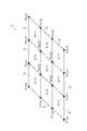
ローラ車両1には、盛土(地盤)の締固め状態を測定する締固め状態測定装置3が搭載されている。締固め状態測定装置3では、例えば、盛土された盛土領域A(図3参照)を正方形状の締固め管理ブロック(締固め対象区域)Dに区画して、締固め管理ブロックD毎に盛土が充分に締め固められたか否かを判定する。 The
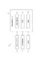
図2に示されるように、締固め状態測定装置3は、車体2の前方及び後方の地盤高さを計測する三次元レーザスキャナ(高さ計測部)4と、盛土の沈下量を算出すると共に、盛土が締め固められたか否かを判定する締固め情報処理ユニット6と、を備える。また、締固め状態測定装置3は、ローラ車両1の位置情報を取得するGPS位置検出部(位置情報取得部)7を有する。 As shown in FIG. 2, the compaction
GPS位置検出部7は、盛土領域Aにおけるローラ車両1の位置を検出する。GPS位置検出部7は、人工衛星から発信された電波をローラ車両1の上部に設置された受信アンテナで受信することによってローラ車両1の高さ情報を含む位置の三次元座標である位置情報を検出する。ローラ車両1の高さ情報は、後述する地盤高さを測定する際の基準としての位置情報であって必ずしも座標値でなくてもよい。 The
GPS位置検出部7によって取得されたローラ車両1の位置情報は、位置情報を取得した時刻と共に締固め情報処理ユニット6の後述する記憶部10に記憶される。すなわち、測定地点の位置情報及び当該測定地点における地盤高さの計測値を計測した際の時刻が関係付けられて記憶される。 The position information of the
なお、GPS位置検出部7により検出した位置情報を時刻とともに計測することで、ローラ車両1では、盛土領域Aにおけるローラ車両1の移動経路データを作成することができる。また、ローラ車両1は、締固め管理ブロックD毎にローラ車両1による転圧回数を算出することも可能となる。 In addition, by measuring the position information detected by the GPS
三次元レーザスキャナ4は、例えば、車体2の運転室の屋根上に設置されている。三次元レーザスキャナ4は、車体2の前方にレーザ光(検出波)L1を照射して、車体2の前方の地盤の表面形状に関する情報を取得する。また、三次元レーザスキャナ4は、車体2の後方にレーザ光L2を照射して、車体2の後方の地盤の表面形状に関する情報を取得する。三次元レーザスキャナ4は、基準点を起点として距離を測定できるので、レーザ光L1,L2の設定された照射角により地盤高さを算出でき、地盤の高さを計測することができる。例えば、高さ情報は三次元レーザスキャナ4によるレーザ光L1,L2の出射点P4a,P4bを基準点(上下方向における基準点)としてもよい。The three-
三次元レーザスキャナ4において、前方に照射されるレーザ光L1の出射点を出射点P4aとし、後方に照射されるレーザ光L2の出射点を出射点P4bとする。また、レーザ光L1の照射角θ1は、X方向から見た場合において、鉛直方向Zとレーザ光L1の照射方向とが交差する角度である。レーザ光L1の照射角θ2は、X方向から見た場合において、鉛直方向Zとレーザ光L2の照射方向とが交差する角度である。例えば、照射角θ1,θ2は三次元レーザスキャナ4を車体2に取付ける際に設定した値とすることができる。また、レーザ光L1,L2の距離の測定に際して、照射角θ1,θ2を測定してもよい。In the three-
ローラ車両1では、ローラ2a,2bにより盛土を転圧しながら、前方にレーザ光L1を照射し、後方にレーザ光L2を照射して、盛土Aの表面形状に関する情報を取得する。三次元レーザスキャナ4では、レーザ光L1,L2を照射し、盛土Aの表面(以下、「地表S」という)からの反射光を受光することによって、地表Sの三次元座標データを測定する。三次元レーザスキャナ4は、ローラ車両1の走行中にリアルタイムで、車体2の前方(転圧前)の地表S(測定地点Pa0)の三次元座標データを測定すると共に、車体2の後方(転圧後)の地表S(測定地点Pb1)の三次元座標データを測定する。In
三次元レーザスキャナ4は、図1、図4及び図5に示されるように、車体2の前方の地表Sの高さH0(Ha0)と、車体2の後方の地表Sの高さH1(Ha1)を算出する。三次元レーザスキャナ4は、測定地点の三次元座標データに基づいて、高さH0(Ha0),H1(Ha1)を算出する。なお、ローラ車両1は走行しながら、三次元座標データに基づく地表Sの高さH0,H1を算出する。測定した三次元座標データより高さを計測することができる。As shown in FIGS. 1, 4 and 5, the three-
三次元レーザスキャナ4によって算出された地表Sの高さH0,H1に関するデータは、締固め情報処理ユニット6に出力される。Data relating to the heights H0 and H1 of the ground surface S calculated by the three-
締固め情報処理ユニット6は、演算処理を行うCPU、記憶部10となるROM及びRAM、入力信号回路、出力信号回路、電源回路などにより構成されている。締固め情報処理ユニット6では、記憶部10に記憶されたプログラムを実行することで、地盤沈下量算出部8、判定部9が構築される。 The compaction information processing unit 6 includes a CPU that performs arithmetic processing, a ROM and a RAM that serve as the
締固め情報処理ユニット6は、盛土領域Aを予め締固め管理ブロックDに区画する。図3に示されるように、締固め情報処理ユニット6は、締固め管理ブロックDの頂点(x1,y1)、(x1,y2)、(x1,y3)…(x2,y1)、(x2,y2)、(x2,y3)…(x3,y1)、(x3,y2)、(x3,y3)…を定めると共に、各締固め管理ブロックDを領域「X1,Y1」、「X1,Y2」、「X1,Y3」、「X2,Y1」、「X2,Y2」、「X2,Y3」、「X3,Y1」、「X3,Y2」、「X3,Y3」として識別する。The compaction information processing unit 6 partitions the embankment area A into compaction management blocks D in advance. As shown in FIG. 3, the compaction information processing unit 6 includes the apexes (x1 , y1 ), (x1 , y2 ), (x1 , y3 ),... (X2 ) of the compaction management block D. , Y1 ), (x2 , y2 ), (x2 , y3 )... (X3 , y1 ), (x3 , y2 ), (x3 , y3 ). The compaction management block D is assigned to the areas “X1 , Y1 ”, “X1 , Y2 ”, “X1 , Y3 ”, “X2 , Y1 ”, “X2 , Y2 ”, “X2 ”. , Y3 ”,“ X3 , Y1 ”,“ X3 , Y2 ”,“ X3 , Y3 ”.
締固め情報処理ユニット6の記憶部10には、三次元レーザスキャナ4の計測範囲を示す計測位置情報が格納されている。三次元レーザスキャナ4の計測範囲は、単一の締固め管理ブロックD、複数の締固め管理ブロックD又は盛土領域A全体のいずれであってもよい。 The
締固め情報処理ユニット6は、GPS位置検出部7から出力された情報に基づいて、ローラ車両1の位置情報を取得する。締固め情報処理ユニット6は、ローラ車両1が領域「X1,Y1」の各頂点(x2,y1)、(x1,y1)、(x2,y2)、(x1,y2)に一回ずつ到達したときに、領域「X1,Y1」の転圧回数を1加算する。記憶部10は、締固め管理ブロックD毎の転圧回数を記憶する。The compaction information processing unit 6 acquires the position information of the
また、記憶部10は、沈下量ΔHの判定閾値に関する情報を記憶する。また、記憶部10は、三次元レーザスキャナ4で計測された三次元座標データに基づく地表Sの高さH0,H1に関するデータ、及び当該三次元座標データが計測されたときの車体2の位置情報が記憶されている。In addition, the
また、締固め情報処理ユニット6は、時刻情報を取得するためのタイマーを有する。高さH0,H1に関するデータを記憶部10に記憶する際には、締固め情報処理ユニット6は、高さH0,H1に関するデータと共に、そのデータを取得した時刻を示す時刻情報を記憶する。Moreover, the compaction information processing unit 6 has a timer for acquiring time information. When storing the data related to the heights H0 and H1 in the
地盤沈下量算出部8は、図5に示されるように、ローラ車両1の通過前の測定地点Paにおける地盤の高さ(前方の地盤高さの計測値)Ha0と、ローラ車両1の通過後の測定地点Paにおける地盤の高さ(後方の地盤高さの計測値)Ha1との差である沈下量ΔH(=Ha0−Ha1)を算出する。ローラ車両1は、走行しながら沈下量ΔHを算出する。Ground subsidence
また、地盤沈下量算出部8は、測定位置同士を特定するための測定位置照合部を含んでいる。測定位置照合部は、同一の測定位置について、転圧前の高さに関するデータと、転圧後の高さに関するデータとを照合する。例えば、車体2から測定位置までの距離に関するデータ、及び車体2の位置情報に基づいて、同一の測定位置について転圧前後の高さに関するデータを照合する。 The ground subsidence
図5では、図示右側から左側へ移動するローラ車両1が示されている。右側に示されたローラ車両1は、時刻t0において位置Pt0に存在している。この右側のローラ車両1は、前方に照射したレーザ光L1によって測定地点Paの地盤の高さHa0を計測している。このとき、測定地点Paは、位置Pt0に存在する車体2の基準位置から距離La0(=l1sinθ1)前方に位置している。FIG. 5 shows a
左側に示されたローラ車両1は、時刻t1において位置Pt1に存在している。ローラ車両1は、位置Pt0から位置Pt1に移動する間に測定地点Paを転圧している。この左側のローラ車両1は、測定地点Paを通過した後において、後方に照射したレーザ光L2によって測定地点Paの地盤の高さHa1を計測している。このとき、測定地点Paは、位置Pt1に存在する車体2の基準位置から距離La1(=l2sinθ2)後方に位置している。The
地盤沈下量算出部8は、GPS位置検出部7で取得されたローラ車両1の位置情報及び車体2の基準位置からの距離La0に基づいて、通過前の高さHa0を測定した際の測定地点Paの絶対位置を特定する。特定された絶対位置に関する情報及び当該測定地点Paにおける通過前の高さHa0の計測値は、記憶部10に記憶される。The ground subsidence
地盤沈下量算出部8は、GPS位置検出部7で取得されたローラ車両1の位置情報及び車体2の基準位置からの距離La1に基づいて、通過後の高さHa1を測定した際の測定地点Paの絶対位置を特定する。特定された絶対位置に関する情報及び当該測定地点Paにおける通過後の高さHa1の計測値は、記憶部10に記憶される。The ground subsidence
地盤沈下量算出部8は、記憶部10に記憶されているデータを照合して、同一の測定地点Paの転圧前後の地盤の高さHa0,Ha1を特定して、沈下量ΔH(=Ha0−Ha1)を算出する。The ground settlement
判定部9は、例えば沈下量ΔHが判定閾値以下であるか否かを判定し、締固めの終了を判定する。また、判定部9は、前回(N−1回目)の沈下量ΔHN−1と、今回(N回目)の沈下量ΔHNとの差分である沈下量変化値に基づいて、締固めの終了を判定してもよい。The
なお、算出される地盤の高さは、例えば、締固め管理ブロックD内の各測定点の高さの平均値としてもよい。地盤沈下量算出部8は、ローラ2a,2bの通過に合わせて、沈下量ΔHを算出する。 The calculated ground height may be, for example, an average value of the heights of the respective measurement points in the compaction management block D. The ground settlement
また、締固め情報処理ユニット6には、表示部11が接続されている。表示部11は、例えば、車体2の姿勢、地盤の高さH1,H2、沈下量ΔH、転圧回数、ローラ車両1の走行位置などに関する情報を表示してもよい。A
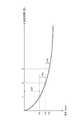
図6は、転圧回数と盛土の地盤の高さとの関係を示すグラフである。図6では横軸に転圧回数(回)を示し、縦軸に同一の測定地点における盛土の地盤の高さを示す。沈下量ΔH1は、転圧回数が1回目であるときの沈下量である。沈下量ΔHNは、転圧回数がN回目であるときの沈下量である(Nは自然数)。なお、一般的に盛土は振動ローラ2aの転圧回数Nが少ないほど大きく沈下するので、転圧回数Nが増えるほど盛土の沈下量ΔHNは減少していく。判定部9では、沈下量ΔHNが判定閾値以下となった場合に、転圧を終了すると判定する。FIG. 6 is a graph showing the relationship between the number of rolling times and the height of the ground of the embankment. In FIG. 6, the horizontal axis indicates the number of times of rolling (times), and the vertical axis indicates the height of the ground of the embankment at the same measurement point. The amount of settlement ΔH1 is the amount of settlement when the number of rolling operations is the first time. The amount of settlement ΔHN is the amount of settlement when the number of rolling operations is the Nth (N is a natural number). In general, as the embankment sinks more greatly as the rolling rolling number N of the
次に、図7を参照して、締固め状態測定方法について説明する。 Next, the compaction state measuring method will be described with reference to FIG.
まず、締固め情報処理ユニット6は、盛土領域Aにおける締固め管理ブロックDの設定を行う(ステップS1)。ステップS1において、ローラ2a,2bによる盛土の転圧が行われる前に盛土領域Aが区画され、正方形状の締固め管理ブロックDが定められる。 First, the compaction information processing unit 6 sets a compaction management block D in the embankment area A (step S1). In step S1, the embankment area A is divided before the rolling of the embankment by the
そして、ローラ車両1を走行させて、ローラ2a,2bによる盛土領域Aの転圧を開始する(ステップS2)。また、GPS位置検出部7は、ローラ車両1の位置情報を取得する。GPS位置検出部7は、盛土領域A上におけるローラ車両1の移動経路を検出する。GPS位置検出部7は、ローラ車両1の移動経路に基づいて転圧回数を計数する。例えば、締固め管理ブロックDの各頂点が1回ずつ踏まれている場合には、転圧回数が1加算される。 Then, the
また、締固め状態測定装置3は、GPS位置検出部7によってローラ車両1の位置情報を取得する(ステップS3)。取得した位置情報は、記憶部10に記憶される。 Moreover, the compaction
また、締固め状態測定装置3では、ローラ車両1による転圧が行われている際に(走行しながら)、転圧前の地表Sの高さHa0及び転圧後の地表Sの高さHb1を計測する(ステップS4:地盤高さ計測工程)。三次元レーザスキャナ4は、車体2の前方にレーザ光L1を照射すると共に、車体2の後方にレーザ光L2を照射する。三次元レーザスキャナ4は、地表Sの表面形状データに基づいて、転圧前後の盛土の地表の高さHa0,Hb1を計測する。三次元レーザスキャナ4は、計測結果を締固め情報処理ユニット6に出力する。Further, in the compaction
ローラ車両1が移動して転圧している間、ステップS3,S4の処理を並行して行っている。地盤沈下量算出部8は、ローラ車両1の位置情報及び車体2の基準位置からの距離La0に基づいて、通過前の高さHa0を測定した際の測定地点Paの絶対位置を特定する。同様に、地盤沈下量算出部8は、ローラ車両1の位置情報及び車体2の基準位置からの距離La1に基づいて、通過後の高さHa1を測定した際の測定地点Paの絶対位置を特定する。特定された絶対位置に関する情報及び当該測定地点Paにおける通過前の高さHa0の計測値及び通過後の高さHa1は、記憶部10に記憶される。While the
次に、締固め状態測定装置3は、同一の測定地点における転圧前の地盤の高さの計測値と、転圧後の地盤の高さの計測値とを特定する(ステップS5)。地盤沈下量算出部8は、記憶部10に記憶されているデータを照合して、同一の測定地点Paの転圧前後の地盤の高さHa0,Ha1を特定する。Next, the compaction
次に、地盤沈下量算出部8は、沈下量ΔHを算出する(ステップS6、地盤沈下量算出工程)。地盤沈下量算出部8は、ステップS5で特定された同一の測定地点Paの転圧前後の地盤の高さHa0,Ha1に基づいて、沈下量ΔH(=Ha0−Ha1)を算出する。Next, the ground settlement
次に、締固め状態測定装置3の判定部9は、沈下量ΔHが判定閾値以下であるか否かを判定する(ステップS7)。沈下量ΔHが判定閾値以下である場合には、その回の転圧により、ローラ車両1による転圧を終了すると決定する。沈下量ΔHが判定閾値以下ではない場合には、ローラ車両1による転圧を継続して転圧回数を増加し、ステップS3〜ステップS7を繰り返す。 Next, the
また、締固め状態測定装置3は、表示部11を用いて各種情報を表示する。締固め情報処理ユニット6は、例えば、転圧回数、転圧前の盛土の高さH0、転圧後の盛土の高さH1、沈下量ΔHに関する情報を、表示部11に表示させる。In addition, the compaction
このような締固め状態測定装置3では、ローラ車両1を移動させて締固めを行いながら、車体2に搭載された三次元レーザスキャナ4から光を照射して、ローラ車両1の前方の地盤高さと、ローラ車両1の後方の地盤高さとを計測する。これにより、同一の測定地点について、ローラ車両1の通過前の地盤高さの計測値と、ローラ車両1の通過後の地盤高さの計測値とを比較して、リアルタイムで沈下量ΔHを算出することが可能である。事前に施工試験を行う必要がなくなるので、締固め管理の手間を低減して、作業効率の向上を図ることができる。 In such a compaction
また、ローラ車両1が測定地点を通過した直後に沈下量ΔHを算出可能であるので、通過前の地盤高さの計測時刻と通過後の地盤高さの計測時刻とに大きな差が生じないようにすることができる。従来の技術では、前回の転圧時の計測値と、今回の転圧時の計測値とを比較しているので、時間差が大きくGPSにおける誤差要因の影響が大きくなっていた。この締固め状態測定装置3では、ローラ車両1の通過前と通過後の計測値に基づいて沈下量を測定しているので、時間差を小さくして、GPSにおける誤差要因の影響を抑制することができる。その結果、沈下量ΔHの測定精度を向上させることができる。 Further, since the subsidence amount ΔH can be calculated immediately after the
また、締固め状態測定装置3では、リアルタイムで沈下量ΔHが計測されるので、沈下量の変化を素早く把握して、沈下量ΔHの変化に基づいて、所要の沈下量に達しているか否かを判断することができる。この判断に基づいて、転圧の終了時を適切に判定することができる。その結果、沈下量ΔHの変化が少ない場合において、不要な転圧作業の継続が防止され、工期の短縮を図ることができる。また、リアルタイムで沈下量ΔHが計測されるので、締固め管理の迅速化を図ることができる。従来の管理方法では、事前に決定された回数分、転圧を実行していたので、沈下量ΔHが変化しない状態となっていても、そのまま、転圧作業を継続していた。 Further, the compaction
(第2実施形態)
次に、図8を参照して、第2実施形態に係る地盤の締固め状態測定装置、締固め状態測定方法、及び締固め機械について説明する。第2実施形態の説明において、第1実施形態の説明と同様の説明は省略する。(Second Embodiment)
Next, a ground compaction state measuring apparatus, compaction state measuring method, and compaction machine according to the second embodiment will be described with reference to FIG. In the description of the second embodiment, the same description as that of the first embodiment is omitted.
第2実施形態に係る締固め状態測定装置3Bが、第1実施形態に係る締固め状態測定装置3と違う点は、ローラ車両1の車速(移動速度)を検出する車速センサ(移動速度検出部)12を備える点である。車速センサ12は、起振ローラ2aの回転角度を計測して、ローラ車両1の車速を検出する。検出された車速に関するデータは、締固め情報処理ユニット6に出力される。 The compacted
地盤沈下量算出部8の測定位置照合部は、ローラ車両1の車速に基づいて、ローラ車両1の移動距離を算出して、車体2の水平方向における基準位置を特定する。測定位置照合部では、例えば任意の位置を基点として設定し、この基点からの移動距離(走行履歴情報)に基づいて、測定地点を特定する。 The measurement position collation unit of the ground subsidence
例えば、図5に示されるように、時刻t0における車体2の位置Pt0を基点として設定する。そして、ローラ車両1の車速及び移動時間に基づいて、ローラ車両1の位置Pt1を特定する。これにより、通過前の測定地点Paの地盤高さを計測した後に、測定地点Paを通過して転圧を行い、所定時間経過後に、通過後の測定地点Paの地盤高さを計測し、この通過後の計測値を特定することができる。For example, as shown in FIG. 5, the position Pt0 of the
このように、ローラ車両1の車速及び移動時間に基づいて、転圧前後の測定地点Paの地盤高さの計測値を特定して、測定地点Paにおける沈下量を算出することができる。なお、ローラ車両1が等速で移動する場合には、時間の経過に基づいて、転圧前後の同一の測定地点同士の計測値を特定することができる。Thus, based on the vehicle speed and the travel time of the
(第3実施形態)
次に、図9を参照して、第3実施形態に係る地盤の締固め状態測定装置、締固め状態測定方法、及び締固め機械について説明する。第3実施形態の説明において、第1,第2実施形態の説明と同様の説明は省略する。(Third embodiment)
Next, a ground compaction state measuring apparatus, compaction state measuring method, and compaction machine according to a third embodiment will be described with reference to FIG. In the description of the third embodiment, the same description as that of the first and second embodiments is omitted.
図9に示される第3実施形態のローラ車両1Bが、図1に示される第1実施形態のローラ車両1と異なる点は、三次元レーザスキャナ14A,14Bの配置が異なる点である。ローラ車両1Bでは、車体2の前部に三次元レーザスキャナ14Aが設けられ、車体2の後部に三次元レーザスキャナ14Bが設けられている。三次元レーザスキャナ14A,14Bにおけるレーザ光の出射点P14a,P14bは、車体2を水平面に載置したときに、同じ高さ位置となるように配置されている。締固め状態測定装置3は、車体2の前方の盛土の高さを計測する前方高さ計測部として、三次元レーザスキャナ14Aを備え、車体2の後方の盛土の高さを計測する後方高さ計測部として、三次元レーザスキャナ14Bを備える。The roller vehicle 1B of the third embodiment shown in FIG. 9 is different from the
三次元レーザスキャナ14Aは、例えば、車体2の運転室より前方に張り出すボンネット部に設けられている。三次元レーザスキャナ14Aは、例えば、ボンネット部の正面(前面)であり、前輪である振動ローラ2aより上方に配置されている。三次元レーザスキャナ14Aは、車体2の前方に向けてレーザ光L1を照射する。三次元レーザスキャナ14Aは、転圧前の盛土の地表S上の測定地点Pa0の高さを測定する。The three-dimensional laser scanner 14 </ b> A is provided, for example, in a bonnet portion that projects forward from the cab of the
三次元レーザスキャナ14Bは、例えば、車体2の運転室の背面(後面)に設けられている。三次元レーザスキャナ14Bは、車体2の後方に向けてレーザ光L2を照射する。三次元レーザスキャナ14Bは、転圧後の盛土の地表S上の測定地点Pb1の高さを測定する。The three-
このような第3実施形態に係る締固め状態測定装置3においても、ローラ車両1Bに搭載された三次元レーザスキャナ14Aから前方にレーザ光を照射して、ローラ車両1Bの通過前の盛土の高さH0を計測し、三次元レーザスキャナ14Bから後方にレーザ光を照射して、ローラ車両1Bの通過後の盛土の高さH1を計測して、沈下量ΔHを算出することができる。これにより、転圧前後の地盤の高さを測定する際の時間差を短くして、GPSにおける誤差要因の影響を抑制することができる。また、位置情報を取得しないで、単に前方の地盤高さと後方の地盤高さの差により沈下量を算出することも可能である。Also in the compaction
また、締固め状態測定装置3では、三次元レーザスキャナ14Aを車体2の前方の地表Sに近付けて配置することができ、三次元レーザスキャナ14Bを車体2の後方の地表Sに近付けて配置することができる。これにより、レーザ光の出射点P14a,P14bとを地表Sに近付けることで、レーザ光の照射距離を短くして誤差要因を減らして測定精度の向上を図ることができる。 Further, in the compaction
(第4実施形態)
次に、図10を参照して、第4実施形態に係る地盤の締固め状態測定装置、締固め状態測定方法、及び締固め機械について説明する。第4実施形態の説明において、第1〜第3実施形態の説明と同様の説明は省略する。(Fourth embodiment)
Next, a ground compaction state measuring device, a compaction state measuring method, and a compacting machine according to a fourth embodiment will be described with reference to FIG. In the description of the fourth embodiment, the same description as that of the first to third embodiments is omitted.
図10に示される第4実施形態のローラ車両1Cが、図9に示される第3実施形態のローラ車両1Bと異なる点は、三次元レーザスキャナ15A,15Bの配置が異なる点である。ローラ車両1Cでは、車体2の前部に三次元レーザスキャナ15Aが設けられ、車体2の後部に三次元レーザスキャナ15Bが設けられている。 The
三次元レーザスキャナ15Aは、車体2のボンネットから前方に延びる支持部16によって支持されている。三次元レーザスキャナ15Aは、ローラ2aよりも前方に配置されている。三次元レーザスキャナ15Aは、鉛直方向において下方にレーザ光を照射する。 The three-dimensional laser scanner 15 </ b> A is supported by a
三次元レーザスキャナ15Bは、車体2の運転室の背面から後方に延びる支持部17によって支持されている。三次元レーザスキャナ15Bは、ローラ2bよりも後方に配置されている。三次元レーザスキャナ15Bは、鉛直方向において下方にレーザ光を照射する。 The three-dimensional laser scanner 15 </ b> B is supported by a
このような第4実施形態に係る締固め状態測定装置においても、ローラ車両1Bに搭載された三次元レーザスキャナ15Aからローラ2aより前方の位置にレーザ光を照射して、ローラ車両1Cの通過前の盛土の高さH0を計測し、三次元レーザスキャナ15Bからローラ2bより後方の位置にレーザ光を照射して、ローラ車両1Cの通過後の盛土の高さH1を計測して、沈下量ΔHを算出することができる。これにより、転圧前後の地盤の高さを測定する際の時間差を短くして、GPSにおける誤差要因の影響を抑制することができる。また、位置情報を取得しないで、単に前方の地盤高さと後方の地盤高さの差により沈下量を算出することも可能である。Also in the compaction state measuring apparatus according to the fourth embodiment, a laser beam is irradiated from the three-
(第5実施形態)
次に、図11を参照して第5実施形態に係る地盤の締固め状態測定装置、締固め状態測定方法、及び締固め機械について説明する。第5実施形態の説明において、第1〜第4実施形態の説明と同様の説明は省略する。(Fifth embodiment)
Next, a ground compaction state measuring device, a compaction state measuring method, and a compacting machine according to a fifth embodiment will be described with reference to FIG. In the description of the fifth embodiment, the same description as in the first to fourth embodiments is omitted.
第5実施形態に係る締固め状態測定装置3Cが、第1実施形態に係る締固め状態測定装置3と違う点は、車体2の姿勢を検知する姿勢検知部5を備える点である。 The compaction
姿勢検知部5は、車体2の姿勢を検知するための各種センサとしてジャイロセンサを有する。姿勢検知部5は、車体2の角度を検出する傾斜計としての機能を有する。姿勢検知部5は、車体2の前後方向に延在する軸線(図4参照)Yθ3の水平面(XY面)に対する傾斜角θ3を検出する。車体2が水平面に載置されている場合には、軸線Yθ3は、水平面に平行となる。姿勢検知部5は、ローラ車両1の車幅方向(X方向)に延在するX軸周りの車体2の回転角を計測する。姿勢検知部5は、その他の方向に延在する軸線周りの回転角を計測するものでもよい。The
また、姿勢検知部5は、車体2の3軸(X軸、Y軸、Z軸)周りの角度変化を検出して、車体2の姿勢を算出してもよい。X軸及びY軸は、水平面内で直交する2軸であり、X軸は、車体2の移動方向と交差する車幅方向に延在し、Y軸は、車体2の移動方向に延在する軸である。Z軸は、鉛直方向に延在する軸である。姿勢検知部5は、各種センサから取得した情報に基づいて、車体2の姿勢として、ピッチ、ロール、ヨーを検出することができる。姿勢検知部5は、車体2の姿勢に関する情報を締固め情報処理ユニット6に出力する。また、姿勢検知部5は、例えば車体2の3軸周りの角速度又は角加速度を検出して、車体2の姿勢を算出してもよい。 In addition, the
締固め状態測定装置3Cは、姿勢検知部5によって検知された車体2の姿勢に基づいて、測定位置を補正する。また、締固め状態測定装置3Cは、姿勢検知部5によって検知された車体2の姿勢に基づいて、前方の地盤高さHa0、または後方の地盤高さHb1の計測値を補正してもよい(図4参照)。The compaction
例えば、締固め状態測定装置3Cは、姿勢検知部5によって検知された車体2の傾斜角θ3を考慮して、レーザ光L1の照射角θ1を算出し、前方の地盤高さHa0を算出することができる(図4参照)。同様に、締固め状態測定装置3Cは、姿勢検知部5によって検知された車体2の傾斜角θ3を考慮して、レーザ光L2の照射角θ2を算出し、後方の地盤高さHb1を算出することができる。For example, the compaction
このような第5実施形態に係る締固め状態測定装置3Cにおいても、ローラ車両1に搭載された三次元レーザスキャナ4からローラ2aより前方の位置にレーザ光L1を照射して、ローラ車両1の通過前の盛土の高さH0を計測し、三次元レーザスキャナ4からローラ2bより後方の位置にレーザ光L2を照射して、ローラ車両1の通過後の盛土の高さH1を計測して、沈下量ΔHを算出することができる。これにより、事前の施工試験を行う必要がなく、締固め管理の手間を低減し、作業効率の向上を図ることができる。Also in compaction
本発明は、前述した実施形態に限定されず、本発明の要旨を逸脱しない範囲で下記のような種々の変形が可能である。 The present invention is not limited to the above-described embodiments, and various modifications as described below are possible without departing from the gist of the present invention.
上記実施形態に係る締固め状態測定装置の締固め情報処理ユニットは、高さ基準を補正する高さ位置照合部を備える構成でもよい。高さ位置照合部は、例えば、GPS位置検出部7で検出されたローラ車両1の高さ情報に基づいて、各測定位置におけるローラ車両1の高さ位置を把握して、車体2の高さ基準を補正してもよい。また、締固め状態測定装置は、ローラ車両1の外部から、車体2の高さ方向における位置を計測し、その計測データに基づいて、各測定位置における車体2の高さ基準としてもよい。 The compaction information processing unit of the compaction state measuring apparatus according to the above embodiment may include a height position matching unit that corrects the height reference. For example, the height position collation unit grasps the height position of the
上記実施形態では、締固め機械をローラ車両として説明しているが、締固め機械は、例えば、振動ローラを有する締固め機械、転圧ローラを有する締固め機械、その他締固め機械でもよい。 In the above embodiment, the compacting machine is described as a roller vehicle. However, the compacting machine may be, for example, a compacting machine having a vibration roller, a compacting machine having a rolling roller, or another compacting machine.
上記実施形態では、三次元レーザスキャナ4を、運転室の屋根上の中央(前後方向の中央)に配置しているが、三次元レーザスキャナ4を、例えば運転室の屋根上において、前後に離間させて配置してもよい。 In the above embodiment, the three-
上記第2実施形態では、三次元レーザスキャナ14A,14Bを前後に離間して配置し、三次元レーザスキャナ14A,14Bによるレーザ光の出射点P14a,P14bの高さ位置を合わせるようにしているが、ローラ車両1Bが水平面に載置された状態において、出射点P14a,P14bの高さ位置は異なっていてもよい。この場合には、出射点P14a,P14bの高さ位置の差及び車体2の傾斜角θ3を考慮して、沈下量ΔHを算出する。In the second embodiment, the three-
上記実施形態の締固め状態測定装置3は、姿勢検知部が締固め機械の幅方向に延在するX軸周りの車体2の回転角を計測する傾斜計を有する構成でもよく、三次元レーザスキャナ4,14A,14BのX軸周りの車体2の回転角を計測する傾斜計を有する構成でもよい。また、傾斜計は、その他の方向に延在する軸線周りの車体2の回転角を計測するものでもよい。 The compaction
また、上記の実施形態では、地盤の高さを計測する高さ計測部として、レーザ光を照射する三次元レーザスキャナを備える構成としているが、例えば光を照射して距離を測定する光波距離測定機等でもよく、その他の検出波を用いて地盤高さを計測する高さ計測部を備える構成でもよい。なお、検出波とは、地盤高さや構造物までの距離を計測可能な電磁波、超音波などをいう。 In the above embodiment, the height measurement unit that measures the height of the ground is configured to include a three-dimensional laser scanner that irradiates laser light. For example, light wave distance measurement that measures the distance by irradiating light. A machine etc. may be sufficient and the composition provided with the height measurement part which measures ground height using other detection waves may be sufficient. The detection wave refers to an electromagnetic wave, an ultrasonic wave, or the like that can measure the ground height or the distance to the structure.
また、上記実施形態の締固め状態測定装置では、GPS位置検出部7を備え、振動ローラ2aの位置を検出しているが、GPS位置検出部7を備えず、振動ローラ2aの位置を検出しない構成でもよい。また、上記実施形態では、盛土領域Aを締固め管理ブロックDに区画した後に、締固め管理ブロックDを設定せずに、盛土の転圧を行ってもよい。 In the compaction state measuring device of the above embodiment, the
また、上記の実施形態では、盛土を転圧して締め固めた際の締固め管理について説明しているが、本実施形態の地盤の締固め状態測定装置、締固め状態測定方法、および締固め機械を、その他の地盤を締固める際の締固め管理に適用してもよい。 In the above embodiment, the compaction management when the embankment is rolled and compacted is described, but the ground compaction state measuring device, compaction state measuring method, and compaction machine of the present embodiment are described. May be applied to compaction management when compacting other ground.
また、上記実施形態では、締固め情報処理ユニット6がローラ車両1に搭載されている構成について説明しているが、締固め情報処理ユニット6がローラ車両1に搭載されていない構成でもよい。例えば、三次元レーザスキャナ4で測定されたデータ、姿勢検知部5で測定されたデータを通信手段によって送信し、外部の締固め情報処理ユニット6で各種処理を行って、沈下量ΔHの算出、締固め状態の判定を行ってもよい。 Moreover, although the said embodiment demonstrated the structure by which the compaction information processing unit 6 is mounted in the
また、車体2の基準位置を、ローラ車両1の外部に設置されたセンサを用いて計測してもよい。例えば、ローラ車両1の外部に設置されたセンサを用いて、車体2の位置及び姿勢を計測して、測定地点を特定してもよい。 Further, the reference position of the
また、ローラ車両1は、ローラ車両1の側方に対してレーザ光を照射して、ローラ車両1によって転圧されている部分に隣接する外側の部分(今回の走行では転圧されていない領域)の地盤高さを測定してもよい。これにより、ローラ車両1によって転圧されていない領域の地盤高さを基準として、ローラ車両1による転圧前後の地盤高さを算出して、沈下量ΔHを算出してもよい。 Further, the
また、ローラ車両1は、ローラ車両1の進行方向を計測する方位計を備え、この方位計によって計測されたデータを用いて、ローラ車両1が直進しているか否かを判定してもよい。これにより、ローラ車両1が直進していない場合には、ローラ車両1の移動方向に応じて、転圧前後の測定地点を特定することができる。 In addition, the
1,1B,1C…ローラ車両(締固め機械)
2…車体、2a…起振ローラ、2b…ローラ、2c…起振装置
3,3B,3C…締固め状態測定装置
4…三次元レーザスキャナ(高さ計測部)
5…姿勢検知部
6…締固め情報処理ユニット
7…GPS位置検出部(位置情報取得部)
8…地盤沈下量算出部
9…判定部
10…記憶部
11…表示部
12…車速センサ(移動速度検出部)
14A,15A…三次元レーザスキャナ(前方高さ計測部)
14B,15B…三次元レーザスキャナ(後方高さ計測部)
16,17…支持部
A…盛土領域
D…管理ブロック
Pa…測定地点。1, 1B, 1C ... Roller vehicle (compaction machine)
DESCRIPTION OF
5 ... posture detection unit 6 ... compaction
8 ... Ground subsidence
14A, 15A ... Three-dimensional laser scanner (front height measurement unit)
14B, 15B ... Three-dimensional laser scanner (rear height measurement unit)
16, 17 ... support portion A ... fill region D ... management blockP a ... measuring location.
Claims (7)
Translated fromJapanese前記締固め機械に搭載され、前記地盤に対して検出波を送信して前記締固め機械の移動方向の前方の地盤高さ及び後方の地盤高さを計測可能な高さ計測部と、
前記締固め機械の通過前の測定地点における前記前方の地盤高さの計測値と前記締固め機械の通過後の前記測定地点における前記後方の地盤高さの計測値との差である地盤沈下量を算出する地盤沈下量算出部と、備える地盤の締固め状態測定装置。A ground compaction state measuring device for measuring a ground compaction state by a compaction machine,
A height measuring unit mounted on the compacting machine, capable of measuring a front ground height and a rear ground height in a moving direction of the compacting machine by transmitting a detection wave to the ground;
Ground subsidence amount, which is the difference between the measured value of the front ground height at the measurement point before passing the compaction machine and the measured value of the rear ground height at the measurement point after passing the compaction machine A ground subsidence amount calculating unit, and a ground compaction state measuring device.
前記締固め機械の後部に設置され、前記後方の地盤高さを計測する後方高さ計測部と、を有する請求項1に記載の地盤の締固め状態測定装置。The height measuring unit is installed at a front portion of the compacting machine, and measures a front height measuring unit that measures the front ground height;
The ground compaction state measuring device according to claim 1, further comprising a rear height measuring unit that is installed at a rear portion of the compacting machine and measures the rear ground height.
前記地盤沈下量算出部は、前記位置情報取得部で取得された前記位置情報に基づいて、前記測定地点を特定し、特定された前記測定地点の前記計測値に基づいて、前記地盤沈下量を算出する請求項1又は2に記載の地盤の締固め状態測定装置。A position information acquisition unit that is mounted on the compacting machine and acquires position information of the compacting machine,
The ground settlement amount calculation unit identifies the measurement point based on the position information acquired by the position information acquisition unit, and calculates the ground settlement amount based on the measurement value of the specified measurement point. The ground compaction state measuring device according to claim 1 or 2, which is calculated.
前記GPS位置検出部は、前記通過前の前記測定地点の前記計測値を測定した際の前記締固め機械の前記位置情報を取得すると共に、前記通過後の前記測定地点の前記計測値を測定した際の前記締固め機械の前記位置情報を取得する請求項3に記載の地盤の締固め状態測定装置。The position information acquisition unit includes a GPS position detection unit that detects a position of the compacting machine,
The GPS position detection unit acquires the position information of the compacting machine when measuring the measurement value of the measurement point before the passage, and measures the measurement value of the measurement point after the passage. The ground compaction state measuring apparatus according to claim 3, wherein the position information of the compacting machine at the time of acquisition is acquired.
前記地盤沈下量算出部は、前記締固め機械の前記移動速度に基づいて、前記測定地点を特定する請求項3又は4に記載の地盤の締固め状態測定装置。The position information acquisition unit includes a movement speed detection unit that detects a movement speed of the compacting machine,
The ground compaction state measuring device according to claim 3 or 4, wherein the ground settlement amount calculation unit identifies the measurement point based on the moving speed of the compacting machine.
前記締固め機械を移動させて前記地盤の締固めを行いながら、前記締固め機械から前記地盤に対して検出波を送信して前記締固め機械の移動方向の前方の地盤高さ及び後方の地盤高さを計測する地盤高さ計測工程と、
前記締固め機械の通過前の測定地点における前記前方の地盤高さの計測値と前記締固め機械の通過後の前記測定地点における前記後方の地盤高さの計測値との差である地盤沈下量を算出する地盤沈下量算出工程と、を含む地盤の締固め状態測定方法。A ground compaction state measuring method for measuring a ground compaction state by a compaction machine,
While the compaction machine is moved to compact the ground, a detection wave is transmitted from the compaction machine to the ground, and the ground height in front of the compaction machine in the moving direction and the ground behind the ground. Ground height measurement process to measure the height,
Ground subsidence amount, which is the difference between the measured value of the front ground height at the measurement point before passing the compaction machine and the measured value of the rear ground height at the measurement point after passing the compaction machine A ground subsidence amount calculating step, and a ground compaction state measuring method.
前記地盤を締固めるローラを有する車体と、
前記車体に取り付けられており、前記地盤に対して検出波を送信して前記締固め機械の移動方向の前方の地盤高さ及び後方の地盤高さを計測可能な高さ計測部と、
前記車体の通過前の測定地点における前記前方の地盤高さの計測値と前記車体の通過後の前記測定地点における前記後方の地盤高さの計測値との差である地盤沈下量を算出する地盤沈下量算出部と、を備える締固め機械。A compacting machine for compacting the ground,
A vehicle body having a roller for compacting the ground;
A height measuring unit attached to the vehicle body, capable of measuring a front ground height and a rear ground height in a moving direction of the compacting machine by transmitting a detection wave to the ground;
A ground for calculating a ground subsidence amount that is a difference between a measured value of the front ground height at the measurement point before the vehicle body passes and a measured value of the rear ground height at the measurement point after the vehicle body passes. A compaction machine comprising a settlement amount calculation unit.
Priority Applications (1)
| Application Number | Priority Date | Filing Date | Title |
|---|---|---|---|
| JP2016020637AJP6567440B2 (en) | 2016-02-05 | 2016-02-05 | Ground compaction state measuring device, compaction state measuring method, and compaction machine |
Applications Claiming Priority (1)
| Application Number | Priority Date | Filing Date | Title |
|---|---|---|---|
| JP2016020637AJP6567440B2 (en) | 2016-02-05 | 2016-02-05 | Ground compaction state measuring device, compaction state measuring method, and compaction machine |
Publications (2)
| Publication Number | Publication Date |
|---|---|
| JP2017137729A JP2017137729A (en) | 2017-08-10 |
| JP6567440B2true JP6567440B2 (en) | 2019-08-28 |
Family
ID=59565595
Family Applications (1)
| Application Number | Title | Priority Date | Filing Date |
|---|---|---|---|
| JP2016020637AActiveJP6567440B2 (en) | 2016-02-05 | 2016-02-05 | Ground compaction state measuring device, compaction state measuring method, and compaction machine |
Country Status (1)
| Country | Link |
|---|---|
| JP (1) | JP6567440B2 (en) |
Families Citing this family (62)
| Publication number | Priority date | Publication date | Assignee | Title |
|---|---|---|---|---|
| JP7164142B2 (en)* | 2017-12-27 | 2022-11-01 | 学校法人立命館 | Arithmetic device, construction method, and computer program |
| KR102146783B1 (en)* | 2018-04-09 | 2020-08-24 | 군산대학교산학협력단 | Construction method for embankmet ground structured using high water content dredged cohesive soil |
| US11641800B2 (en) | 2020-02-06 | 2023-05-09 | Deere & Company | Agricultural harvesting machine with pre-emergence weed detection and mitigation system |
| US11957072B2 (en) | 2020-02-06 | 2024-04-16 | Deere & Company | Pre-emergence weed detection and mitigation system |
| US11467605B2 (en) | 2019-04-10 | 2022-10-11 | Deere & Company | Zonal machine control |
| US11240961B2 (en) | 2018-10-26 | 2022-02-08 | Deere & Company | Controlling a harvesting machine based on a geo-spatial representation indicating where the harvesting machine is likely to reach capacity |
| US12069978B2 (en) | 2018-10-26 | 2024-08-27 | Deere & Company | Predictive environmental characteristic map generation and control system |
| US11178818B2 (en) | 2018-10-26 | 2021-11-23 | Deere & Company | Harvesting machine control system with fill level processing based on yield data |
| US11079725B2 (en) | 2019-04-10 | 2021-08-03 | Deere & Company | Machine control using real-time model |
| US11589509B2 (en) | 2018-10-26 | 2023-02-28 | Deere & Company | Predictive machine characteristic map generation and control system |
| US11672203B2 (en) | 2018-10-26 | 2023-06-13 | Deere & Company | Predictive map generation and control |
| US11653588B2 (en) | 2018-10-26 | 2023-05-23 | Deere & Company | Yield map generation and control system |
| US11778945B2 (en) | 2019-04-10 | 2023-10-10 | Deere & Company | Machine control using real-time model |
| US11234366B2 (en) | 2019-04-10 | 2022-02-01 | Deere & Company | Image selection for machine control |
| KR102135013B1 (en)* | 2019-06-17 | 2020-07-16 | 한국생산기술연구원 | Apparatus for measuring sinkage caused by tractor wheel using 2D LiDAR sensor and, measuring methods using the same |
| US12035648B2 (en) | 2020-02-06 | 2024-07-16 | Deere & Company | Predictive weed map generation and control system |
| US12329148B2 (en) | 2020-02-06 | 2025-06-17 | Deere & Company | Predictive weed map and material application machine control |
| US12225846B2 (en) | 2020-02-06 | 2025-02-18 | Deere & Company | Machine control using a predictive map |
| US11477940B2 (en) | 2020-03-26 | 2022-10-25 | Deere & Company | Mobile work machine control based on zone parameter modification |
| US11849671B2 (en) | 2020-10-09 | 2023-12-26 | Deere & Company | Crop state map generation and control system |
| US11927459B2 (en) | 2020-10-09 | 2024-03-12 | Deere & Company | Machine control using a predictive map |
| US11889788B2 (en) | 2020-10-09 | 2024-02-06 | Deere & Company | Predictive biomass map generation and control |
| US11675354B2 (en) | 2020-10-09 | 2023-06-13 | Deere & Company | Machine control using a predictive map |
| US11983009B2 (en) | 2020-10-09 | 2024-05-14 | Deere & Company | Map generation and control system |
| US11864483B2 (en) | 2020-10-09 | 2024-01-09 | Deere & Company | Predictive map generation and control system |
| US11849672B2 (en) | 2020-10-09 | 2023-12-26 | Deere & Company | Machine control using a predictive map |
| US12419220B2 (en) | 2020-10-09 | 2025-09-23 | Deere & Company | Predictive map generation and control system |
| US11871697B2 (en) | 2020-10-09 | 2024-01-16 | Deere & Company | Crop moisture map generation and control system |
| US12069986B2 (en) | 2020-10-09 | 2024-08-27 | Deere & Company | Map generation and control system |
| US11650587B2 (en) | 2020-10-09 | 2023-05-16 | Deere & Company | Predictive power map generation and control system |
| US11946747B2 (en) | 2020-10-09 | 2024-04-02 | Deere & Company | Crop constituent map generation and control system |
| US11592822B2 (en) | 2020-10-09 | 2023-02-28 | Deere & Company | Machine control using a predictive map |
| US20220110238A1 (en) | 2020-10-09 | 2022-04-14 | Deere & Company | Machine control using a predictive map |
| US11874669B2 (en) | 2020-10-09 | 2024-01-16 | Deere & Company | Map generation and control system |
| US12013245B2 (en) | 2020-10-09 | 2024-06-18 | Deere & Company | Predictive map generation and control system |
| US11895948B2 (en) | 2020-10-09 | 2024-02-13 | Deere & Company | Predictive map generation and control based on soil properties |
| US11635765B2 (en) | 2020-10-09 | 2023-04-25 | Deere & Company | Crop state map generation and control system |
| US11844311B2 (en) | 2020-10-09 | 2023-12-19 | Deere & Company | Machine control using a predictive map |
| US11711995B2 (en) | 2020-10-09 | 2023-08-01 | Deere & Company | Machine control using a predictive map |
| US12386354B2 (en) | 2020-10-09 | 2025-08-12 | Deere & Company | Predictive power map generation and control system |
| US11474523B2 (en) | 2020-10-09 | 2022-10-18 | Deere & Company | Machine control using a predictive speed map |
| US12178158B2 (en) | 2020-10-09 | 2024-12-31 | Deere & Company | Predictive map generation and control system for an agricultural work machine |
| US11727680B2 (en) | 2020-10-09 | 2023-08-15 | Deere & Company | Predictive map generation based on seeding characteristics and control |
| US20220110258A1 (en) | 2020-10-09 | 2022-04-14 | Deere & Company | Map generation and control system |
| US11825768B2 (en) | 2020-10-09 | 2023-11-28 | Deere & Company | Machine control using a predictive map |
| US11845449B2 (en) | 2020-10-09 | 2023-12-19 | Deere & Company | Map generation and control system |
| US12422847B2 (en) | 2020-10-09 | 2025-09-23 | Deere & Company | Predictive agricultural model and map generation |
| US12250905B2 (en) | 2020-10-09 | 2025-03-18 | Deere & Company | Machine control using a predictive map |
| US11889787B2 (en) | 2020-10-09 | 2024-02-06 | Deere & Company | Predictive speed map generation and control system |
| US12127500B2 (en) | 2021-01-27 | 2024-10-29 | Deere & Company | Machine control using a map with regime zones |
| US12229886B2 (en) | 2021-10-01 | 2025-02-18 | Deere & Company | Historical crop state model, predictive crop state map generation and control system |
| US12310286B2 (en) | 2021-12-14 | 2025-05-27 | Deere & Company | Crop constituent sensing |
| US12302791B2 (en) | 2021-12-20 | 2025-05-20 | Deere & Company | Crop constituents, predictive mapping, and agricultural harvester control |
| US12245549B2 (en) | 2022-01-11 | 2025-03-11 | Deere & Company | Predictive response map generation and control system |
| US12082531B2 (en) | 2022-01-26 | 2024-09-10 | Deere & Company | Systems and methods for predicting material dynamics |
| US12295288B2 (en) | 2022-04-05 | 2025-05-13 | Deere &Company | Predictive machine setting map generation and control system |
| US12284934B2 (en) | 2022-04-08 | 2025-04-29 | Deere & Company | Systems and methods for predictive tractive characteristics and control |
| US12058951B2 (en) | 2022-04-08 | 2024-08-13 | Deere & Company | Predictive nutrient map and control |
| US12358493B2 (en) | 2022-04-08 | 2025-07-15 | Deere & Company | Systems and methods for predictive power requirements and control |
| US12298767B2 (en) | 2022-04-08 | 2025-05-13 | Deere & Company | Predictive material consumption map and control |
| CN114855743A (en)* | 2022-04-27 | 2022-08-05 | 交通运输部公路科学研究所 | A soil foundation compaction monitoring device and method for an airport prefabricated runway |
| CN115491952A (en)* | 2022-09-30 | 2022-12-20 | 湖南交通国际经济工程合作有限公司 | Highway subgrade road surface wisdom compaction monitored control system |
Family Cites Families (5)
| Publication number | Priority date | Publication date | Assignee | Title |
|---|---|---|---|---|
| JPH06167326A (en)* | 1992-11-30 | 1994-06-14 | Hazama Gumi Ltd | Management method of compaction degree |
| JPH0979924A (en)* | 1995-09-13 | 1997-03-28 | Hazama Gumi Ltd | Method of estimating compaction degree |
| JP2004257190A (en)* | 2003-02-27 | 2004-09-16 | Taisei Corp | Embankment management method |
| JP6161475B2 (en)* | 2013-09-05 | 2017-07-12 | 鹿島建設株式会社 | Compaction management method and compaction management system |
| JP6298313B2 (en)* | 2014-02-18 | 2018-03-20 | 鹿島建設株式会社 | Ground stiffness measuring device, compaction machine, and ground stiffness measuring method |
- 2016
- 2016-02-05JPJP2016020637Apatent/JP6567440B2/enactiveActive
Also Published As
| Publication number | Publication date |
|---|---|
| JP2017137729A (en) | 2017-08-10 |
Similar Documents
| Publication | Publication Date | Title |
|---|---|---|
| JP6567440B2 (en) | Ground compaction state measuring device, compaction state measuring method, and compaction machine | |
| US10018611B2 (en) | Soil compaction system and method | |
| AU2016201809B2 (en) | Determining milled volume or milled area of a milled surface | |
| JP6161475B2 (en) | Compaction management method and compaction management system | |
| JP6641535B2 (en) | Structure measuring device, measuring point correcting device, and measuring point correcting method | |
| US20180002882A1 (en) | An Impact Compactor, Compaction System and a Method of Obtaining Soil Strength | |
| JP6757749B2 (en) | Work machine management system, work machine, work machine management method | |
| EP3335003B1 (en) | Point cloud based surface construction | |
| US20160168806A1 (en) | System and method for determining ground stiffness | |
| JP6764392B2 (en) | Road surface cutting method and road surface cutting machine | |
| RU2526793C1 (en) | Method to determine condition of motor road surface by its geometric parameters | |
| US10329740B2 (en) | Earth moving machine, range finder arrangement and method for 3D scanning | |
| Brzeziński et al. | Soil compaction monitoring via photogrammetric settlement measurement–Feasibility study | |
| JPH0748809A (en) | Rolling compactor | |
| KR101921959B1 (en) | Autonomous Compaction Device, Method and Program to improve a quality of a compaction near pipes | |
| CN105783925A (en) | System and method for positioning drill jambo body | |
| US12060684B2 (en) | System for compaction measurements | |
| US20250052024A1 (en) | A system and method to measure a deformation of a geomaterial portion due to compaction of the geomaterial portion | |
| WO2024047785A1 (en) | Survey system and survey method | |
| JP2009114691A (en) | Management method of embankment density | |
| Magnusson et al. | 3d modelling for underground mining vehicles | |
| CN120610285A (en) | Real settlement monitoring method and monitoring equipment for earth-rock dam construction period | |
| CN117630345A (en) | Compaction quality detection method, controller, system, road roller and storage medium | |
| GB2571103A (en) | An autonomous vehicle system | |
| Thomsen et al. | An integrated real time GPS-and laserscanner system for high precision guidance in harsh environment |
Legal Events
| Date | Code | Title | Description |
|---|---|---|---|
| A621 | Written request for application examination | Free format text:JAPANESE INTERMEDIATE CODE: A621 Effective date:20181003 | |
| A977 | Report on retrieval | Free format text:JAPANESE INTERMEDIATE CODE: A971007 Effective date:20190627 | |
| TRDD | Decision of grant or rejection written | ||
| A01 | Written decision to grant a patent or to grant a registration (utility model) | Free format text:JAPANESE INTERMEDIATE CODE: A01 Effective date:20190716 | |
| A61 | First payment of annual fees (during grant procedure) | Free format text:JAPANESE INTERMEDIATE CODE: A61 Effective date:20190731 | |
| R150 | Certificate of patent or registration of utility model | Ref document number:6567440 Country of ref document:JP Free format text:JAPANESE INTERMEDIATE CODE: R150 | |
| R250 | Receipt of annual fees | Free format text:JAPANESE INTERMEDIATE CODE: R250 |