JP6563075B2 - catheter - Google Patents
catheterDownload PDFInfo
- Publication number
- JP6563075B2 JP6563075B2JP2018097014AJP2018097014AJP6563075B2JP 6563075 B2JP6563075 B2JP 6563075B2JP 2018097014 AJP2018097014 AJP 2018097014AJP 2018097014 AJP2018097014 AJP 2018097014AJP 6563075 B2JP6563075 B2JP 6563075B2
- Authority
- JP
- Japan
- Prior art keywords
- mesh member
- strand
- protective film
- hollow shaft
- catheter
- Prior art date
- Legal status (The legal status is an assumption and is not a legal conclusion. Google has not performed a legal analysis and makes no representation as to the accuracy of the status listed.)
- Active
Links
Images


Classifications
- A—HUMAN NECESSITIES
- A61—MEDICAL OR VETERINARY SCIENCE; HYGIENE
- A61B—DIAGNOSIS; SURGERY; IDENTIFICATION
- A61B17/00—Surgical instruments, devices or methods
- A61B17/22—Implements for squeezing-off ulcers or the like on inner organs of the body; Implements for scraping-out cavities of body organs, e.g. bones; for invasive removal or destruction of calculus using mechanical vibrations; for removing obstructions in blood vessels, not otherwise provided for
- A61B17/221—Gripping devices in the form of loops or baskets for gripping calculi or similar types of obstructions
- A—HUMAN NECESSITIES
- A61—MEDICAL OR VETERINARY SCIENCE; HYGIENE
- A61M—DEVICES FOR INTRODUCING MEDIA INTO, OR ONTO, THE BODY; DEVICES FOR TRANSDUCING BODY MEDIA OR FOR TAKING MEDIA FROM THE BODY; DEVICES FOR PRODUCING OR ENDING SLEEP OR STUPOR
- A61M25/00—Catheters; Hollow probes
- A61M25/0067—Catheters; Hollow probes characterised by the distal end, e.g. tips
- A61M25/0082—Catheter tip comprising a tool
- A—HUMAN NECESSITIES
- A61—MEDICAL OR VETERINARY SCIENCE; HYGIENE
- A61B—DIAGNOSIS; SURGERY; IDENTIFICATION
- A61B17/00—Surgical instruments, devices or methods
- A61B17/32—Surgical cutting instruments
- A61B17/3205—Excision instruments
- A61B17/32053—Punch like cutting instruments, e.g. using a cylindrical or oval knife
- A—HUMAN NECESSITIES
- A61—MEDICAL OR VETERINARY SCIENCE; HYGIENE
- A61B—DIAGNOSIS; SURGERY; IDENTIFICATION
- A61B17/00—Surgical instruments, devices or methods
- A61B17/22—Implements for squeezing-off ulcers or the like on inner organs of the body; Implements for scraping-out cavities of body organs, e.g. bones; for invasive removal or destruction of calculus using mechanical vibrations; for removing obstructions in blood vessels, not otherwise provided for
- A61B17/22031—Gripping instruments, e.g. forceps, for removing or smashing calculi
- A61B2017/22034—Gripping instruments, e.g. forceps, for removing or smashing calculi for gripping the obstruction or the tissue part from inside
- A—HUMAN NECESSITIES
- A61—MEDICAL OR VETERINARY SCIENCE; HYGIENE
- A61B—DIAGNOSIS; SURGERY; IDENTIFICATION
- A61B17/00—Surgical instruments, devices or methods
- A61B17/22—Implements for squeezing-off ulcers or the like on inner organs of the body; Implements for scraping-out cavities of body organs, e.g. bones; for invasive removal or destruction of calculus using mechanical vibrations; for removing obstructions in blood vessels, not otherwise provided for
- A61B2017/22038—Implements for squeezing-off ulcers or the like on inner organs of the body; Implements for scraping-out cavities of body organs, e.g. bones; for invasive removal or destruction of calculus using mechanical vibrations; for removing obstructions in blood vessels, not otherwise provided for with a guide wire
- A61B2017/22039—Implements for squeezing-off ulcers or the like on inner organs of the body; Implements for scraping-out cavities of body organs, e.g. bones; for invasive removal or destruction of calculus using mechanical vibrations; for removing obstructions in blood vessels, not otherwise provided for with a guide wire eccentric
- A—HUMAN NECESSITIES
- A61—MEDICAL OR VETERINARY SCIENCE; HYGIENE
- A61B—DIAGNOSIS; SURGERY; IDENTIFICATION
- A61B17/00—Surgical instruments, devices or methods
- A61B17/22—Implements for squeezing-off ulcers or the like on inner organs of the body; Implements for scraping-out cavities of body organs, e.g. bones; for invasive removal or destruction of calculus using mechanical vibrations; for removing obstructions in blood vessels, not otherwise provided for
- A61B2017/22079—Implements for squeezing-off ulcers or the like on inner organs of the body; Implements for scraping-out cavities of body organs, e.g. bones; for invasive removal or destruction of calculus using mechanical vibrations; for removing obstructions in blood vessels, not otherwise provided for with suction of debris
- A—HUMAN NECESSITIES
- A61—MEDICAL OR VETERINARY SCIENCE; HYGIENE
- A61B—DIAGNOSIS; SURGERY; IDENTIFICATION
- A61B17/00—Surgical instruments, devices or methods
- A61B17/22—Implements for squeezing-off ulcers or the like on inner organs of the body; Implements for scraping-out cavities of body organs, e.g. bones; for invasive removal or destruction of calculus using mechanical vibrations; for removing obstructions in blood vessels, not otherwise provided for
- A61B17/221—Gripping devices in the form of loops or baskets for gripping calculi or similar types of obstructions
- A61B2017/2215—Gripping devices in the form of loops or baskets for gripping calculi or similar types of obstructions having an open distal end
- A—HUMAN NECESSITIES
- A61—MEDICAL OR VETERINARY SCIENCE; HYGIENE
- A61M—DEVICES FOR INTRODUCING MEDIA INTO, OR ONTO, THE BODY; DEVICES FOR TRANSDUCING BODY MEDIA OR FOR TAKING MEDIA FROM THE BODY; DEVICES FOR PRODUCING OR ENDING SLEEP OR STUPOR
- A61M25/00—Catheters; Hollow probes
- A61M25/0067—Catheters; Hollow probes characterised by the distal end, e.g. tips
- A61M25/0082—Catheter tip comprising a tool
- A61M2025/0096—Catheter tip comprising a tool being laterally outward extensions or tools, e.g. hooks or fibres
- A—HUMAN NECESSITIES
- A61—MEDICAL OR VETERINARY SCIENCE; HYGIENE
- A61M—DEVICES FOR INTRODUCING MEDIA INTO, OR ONTO, THE BODY; DEVICES FOR TRANSDUCING BODY MEDIA OR FOR TAKING MEDIA FROM THE BODY; DEVICES FOR PRODUCING OR ENDING SLEEP OR STUPOR
- A61M25/00—Catheters; Hollow probes
- A61M25/01—Introducing, guiding, advancing, emplacing or holding catheters
- A61M2025/0183—Rapid exchange or monorail catheters
Landscapes
- Health & Medical Sciences (AREA)
- Life Sciences & Earth Sciences (AREA)
- General Health & Medical Sciences (AREA)
- Surgery (AREA)
- Veterinary Medicine (AREA)
- Engineering & Computer Science (AREA)
- Biomedical Technology (AREA)
- Heart & Thoracic Surgery (AREA)
- Public Health (AREA)
- Animal Behavior & Ethology (AREA)
- Anesthesiology (AREA)
- Hematology (AREA)
- Pulmonology (AREA)
- Orthopedic Medicine & Surgery (AREA)
- Vascular Medicine (AREA)
- Nuclear Medicine, Radiotherapy & Molecular Imaging (AREA)
- Biophysics (AREA)
- Medical Informatics (AREA)
- Molecular Biology (AREA)
- Surgical Instruments (AREA)
- Media Introduction/Drainage Providing Device (AREA)
Description
Translated fromJapanese本発明は、血管内の閉塞物を捕獲したり、レトロ用ガイドワイヤを捕獲したりするためのカテーテルに関する。 The present invention relates to a catheter for capturing an obstruction in a blood vessel or capturing a retro guide wire.
従来から、慢性完全閉塞(CTO:Chronic total occlusion)等のように、血管内が閉塞物によって閉塞されてしまう場合がある。このような場合の治療に用いられる医療機器としては、例えば特許文献1に開示されているように、血管内の閉塞物を除去する目的で径方向に拡張又は収縮するように複数のワイヤが互いに編み込まれた閉塞物除去エレメントを備えた脈管閉塞物除去装置(カテーテル)がある。 Conventionally, there are cases where the inside of a blood vessel is occluded by an obstruction, such as chronic total occlusion (CTO). As a medical device used for treatment in such a case, for example, as disclosed in Patent Document 1, a plurality of wires are mutually connected so as to expand or contract in the radial direction in order to remove an obstruction in a blood vessel. There are vascular obstruction removal devices (catheters) with braided obstruction removal elements.
また、例えば特許文献2には、メッシュとしての自己拡張可能なエリアを有するカテーテルが開示されている。そして、かかるカテーテルにあっては、自己拡張可能なエリアの後端部に、カテーテルのルーメンの中へと血流を誘導または方向付けするための漏斗の役割を果たすカバー(保護膜)が備えられている。なお、前記カバーは、接着結合、溶接、又はコーティング等によってメッシュに直接形成されたり、あるいは、機械式締結具を用いた連結等によってメッシュに取り付けられたりしている。 For example, Patent Document 2 discloses a catheter having a self-expandable area as a mesh. Such a catheter is provided with a cover (protective membrane) at the rear end of the self-expandable area that acts as a funnel for guiding or directing blood flow into the lumen of the catheter. ing. The cover is formed directly on the mesh by adhesive bonding, welding, coating, or the like, or attached to the mesh by connection using a mechanical fastener.
さらに、血管内の閉塞物の反対側から挿入されたレトロ用ガイドワイヤを捕獲するために、上記したような径方向に拡張可能なメッシュ状の部材を備えたカテーテルを使用することもよく知られている。 It is also well known to use a catheter with a radially expandable mesh member as described above to capture a retro guidewire inserted from the opposite side of the occlusion in the blood vessel. ing.
しかしながら、上記特許文献1の構成にあっては、拡張された複数のワイヤによって削り取られた閉塞物を細径のカテーテルの先端から取り込む必要があり、取りこぼしが多く、閉塞物を除去する効率が悪いという問題がある。 However, in the configuration of the above-mentioned Patent Document 1, it is necessary to take in an obstruction scraped off by a plurality of expanded wires from the distal end of a small-diameter catheter, so there are many spills and the efficiency of removing the obstruction is poor. There is a problem.
また、レトロ用ガイドワイヤを捕獲する場合には、閉塞物除去エレメントを拡張させてワイヤを起こし、この状態で閉塞物除去エレメントの網目にレトロ用ガイドワイヤを挿通させ、その後、閉塞物除去エレメントを強引に収縮させてワイヤを寝かし、複数のワイヤでレトロ用ガイドワイヤを拘束するため、レトロ用ガイドワイヤが無理に屈曲してしまって、破損するおそれがあるという問題がある。 When capturing the retro guide wire, expand the obstruction removal element to raise the wire, and in this state, insert the retro guide wire into the mesh of the obstruction removal element, and then install the obstruction removal element. Since the wire is laid down forcibly and the retro guide wire is restrained by a plurality of wires, the retro guide wire may be bent forcibly and may be damaged.
また、上記特許文献2の構成にあっては、メッシュの動きに対してカバーの動きの自由度がないため、メッシュの拡張又は収縮が円滑に行えなくなる問題がある。 Moreover, in the structure of the said patent document 2, since there is no freedom degree of a movement of a cover with respect to the movement of a mesh, there exists a problem which cannot perform the expansion or contraction of a mesh smoothly.
そこで本発明は、血管内の閉塞物の除去効率を向上させ、またレトロ用ガイドワイヤを破損させてしまうことがなく、また保護膜を有するメッシュ部材の拡縮を円滑に行うことができるカテーテルを提供することを目的とする。 Accordingly, the present invention provides a catheter that improves the removal efficiency of occlusions in blood vessels, does not damage the retro guide wire, and can smoothly expand and contract the mesh member having a protective film. The purpose is to do.
本発明は、中空シャフトと、前記中空シャフトの先端に接合されたチューブ状のメッシュ部材と、前記メッシュ部材の先端に接合された先端チップと、前記先端チップに接合されたコアワイヤと、を備え、前記メッシュ部材は、径方向に拡縮するように少なくとも第一素線と第二素線とが互いに編み込まれてなり、前記コアワイヤによって、前記メッシュ部材の拡縮が操作可能とされているカテーテルであって、前記メッシュ部材の後端側の内周の少なくとも一部を被覆した保護膜を備え、前記保護膜は、前記第一素線と前記第二素線との何れか一方のみに接合されていることを特徴とするカテーテル。 The present invention comprises a hollow shaft, a tubular mesh member joined to the tip of the hollow shaft, a tip attached to the tip of the mesh member, and a core wire joined to the tip. The mesh member is a catheter in which at least a first strand and a second strand are knitted together so as to expand and contract in the radial direction, and the expansion and contraction of the mesh member can be operated by the core wire. And a protective film covering at least a part of the inner periphery on the rear end side of the mesh member, wherein the protective film is bonded to only one of the first strand and the second strand. A catheter characterized by that.
かかる構成にあっては、前記保護膜によって血管内の閉塞物をカテーテルの先端に案内することができるため、前記閉塞物の除去効率を向上させることができる。また、メッシュ部材に侵入したレトロ用ガイドワイヤをそのまま保護膜の案内作用によってカテーテル内に円滑に誘導することができるため、メッシュ部材の拡縮操作によってレトロ用ガイドワイヤを拘束する必要がなくなり、レトロ用ガイドワイヤを破損させてしまうことがない。さらに、上記態様で前記保護膜が接合されたメッシュ部材にあっては、前記第一素線と前記第二素線とが前記保護膜を介して互いに拘束されてしまうことがないため、前記メッシュ部材の拡縮を円滑に行うことができる。 In such a configuration, the obstruction in the blood vessel can be guided to the distal end of the catheter by the protective film, so that the removal efficiency of the obstruction can be improved. In addition, the retro guide wire that has entered the mesh member can be smoothly guided into the catheter as it is by the guiding action of the protective film, so there is no need to constrain the retro guide wire by the expansion / contraction operation of the mesh member. The guide wire will not be damaged. Furthermore, in the mesh member to which the protective film is bonded in the above-described aspect, the first strand and the second strand are not bound to each other via the protective film. The member can be smoothly expanded and contracted.
また、前記保護膜の後端は、前記中空シャフトの先端の位置まで延びていることが望ましい。 Moreover, it is desirable that the rear end of the protective film extends to the position of the front end of the hollow shaft.
かかる構成にあっては、前記メッシュ部材と前記中空シャフトとの接合部分において、血管内の閉塞物やレトロ用ガイドワイヤを中空シャフト内に漏れなく円滑に誘導することができる。 In such a configuration, the obstruction in the blood vessel and the retro guide wire can be smoothly guided into the hollow shaft without leakage at the joint portion between the mesh member and the hollow shaft.
さらに、前記保護膜の先端部は、前記メッシュ部材の前記第一素線と前記第二素線との何れか一方のみに接合されている一方、前記保護膜の後端部は、前記第一素線と前記第二素線との何れにも接合されていないことが望ましい。 Furthermore, while the front-end | tip part of the said protective film is joined only to either one of said 1st strand of said mesh member and said 2nd strand, the rear-end part of said protective film is said 1st It is desirable that it is not joined to either the strand or the second strand.
かかる構成にあっては、前記メッシュ部材が拡径した際、前記保護膜の先端部はメッシュ部材に追従して径方向に拡張される。これに対し、保護膜の後端部はメッシュ部材の動きに追従しないため、径方向に拡張されない。したがって、かかる構成とすることにより、メッシュ部材が拡径した際の保護膜の形状を、後端方向に向かって縮径した漏斗形状とすることができる。また、保護膜の後端部が、メッシュ部材の第一素線と第二素線との何れにも接合されていないため、血管内におけるカテーテルの柔軟性が損なわれない。 In such a configuration, when the diameter of the mesh member is increased, the tip of the protective film is expanded in the radial direction following the mesh member. On the other hand, since the rear end portion of the protective film does not follow the movement of the mesh member, it is not expanded in the radial direction. Therefore, by adopting such a configuration, the shape of the protective film when the diameter of the mesh member is expanded can be a funnel shape having a diameter reduced toward the rear end direction. Further, since the rear end portion of the protective film is not joined to either the first strand or the second strand of the mesh member, the flexibility of the catheter in the blood vessel is not impaired.
本発明のカテーテルは、血管内の閉塞物の除去効率を向上させ、またレトロ用ガイドワイヤを破損させてしまうことがなく、また保護膜を有するメッシュ部材の拡縮操作を円滑に行うことができる効果がある。 The catheter of the present invention improves the removal efficiency of the obstruction in the blood vessel, does not damage the retro guide wire, and can smoothly perform the expansion / contraction operation of the mesh member having the protective film. There is.
以下、本発明のカテーテルを具体化した実施例を詳細に説明する。ただし、本発明は下記に示す実施例に限定されることはなく、適宜設計変更が可能である。なお、図1(a),図2,及び図4から図7(a)においては、左側が体内に挿入される先端側(遠位側)であり、右側が医師等の手技者によって操作される後端側(近位側、基端側)である。 Hereinafter, the embodiment which actualized the catheter of the present invention is described in detail. However, the present invention is not limited to the examples shown below, and the design can be changed as appropriate. In FIGS. 1 (a), 2 and 4 to 7 (a), the left side is the distal end side (distal side) to be inserted into the body, and the right side is operated by an operator such as a doctor. This is the rear end side (proximal side, proximal end side).
〔実施例1〕
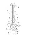
例えば血管内の閉塞物の除去に用いられるカテーテル11は、図1(a),図1(b),図2に示すように、中空シャフト20を備えている。[Example 1]
For example, the
前記中空シャフト20は、内部にルーメン23を有するように中空のチューブ状をなし、先端部と後端部との間に位置する側壁には、後端側へ向かって開口するRXポート21が形成されている。 The
なお、前記中空シャフト20は、例えばポリアミド、ポリアミドエラストマー、ポリオレフィン、ポリエステル、又はポリエステルエラストマー等の樹脂からなるチューブで構成されることが好ましい。また後端側と先端側とで異なる材料が用いられていても構わない。例えば後端側は、ステンレス鋼(SUS304)やNi−Ti合金等の超弾性合金で構成されるものであってもよい。 The
また、前記中空シャフト20の先端22には、メッシュ部材30が接合されている。さらに詳述すると、前記メッシュ部材30は、第一素線31と第二素線32とが互いに編み込まれたチューブ状をなし、前記メッシュ部材30の後端36と前記中空シャフト20の先端22とが接続されて、前記メッシュ部材30と前記中空シャフト20とがほぼ同軸状となるように配置されている。 A
なお、前記メッシュ部材30を構成する前記第一素線31及び前記第二素線32は、例えばステンレス鋼(SUS304)等の金属材からなることが望ましい。特に、少なくとも前記第一素線31と前記第二素線32とのいずれか一方に、放射線不透過性を有する材料(例えば、タングステンやCo−Cr合金)を用いることで、冠動脈造影時に、手技者はメッシュ部材30の位置を正確に把握することができる。 The
さらに、前記メッシュ部材30の先端37には、先端チップ40が接合されている。さらに詳述すると、前記先端チップ40はチューブ状をなし、前記先端チップ40の先端には開口41が形成されている。 Further, a
なお、前記先端チップ40は、ポリウレタン、又はポリウレタンエラストマー等の柔軟な樹脂で形成されていることが望ましい。 The
また、前記先端チップ40の後端には、コアワイヤ50の先端が接合されている。さらに詳述すると、前記コアワイヤ50は、前記中空シャフト20の内部(ルーメン23)に挿通されており、断面が円形であって先端に向かって細径化されたテーパ状の金属製線材で構成されている。そして、後で詳述するように、前記コアワイヤ50を軸方向に操作することで、前記メッシュ部材30を径方向に拡縮することができる。 The tip of the
また、前記中空シャフト20の後端には、コネクタ60が接合されている。 A
さらに、前記メッシュ部材30の後端側35の内周には、薄厚で可撓性を有する保護膜70Aがチューブ状に配設されている。なお、図1(a)及び図2では、理解を助けるために、中空シャフト20、先端チップ40、コネクタ60、並びに、中空シャフト20及びメッシュ部材30内に配置されたコアワイヤ50は、断面図で示している。ただし、保護膜70A内に位置しているコアワイヤ50については、破線で示している。 Further, a thin and flexible protective film 70 </ b> A is disposed in a tube shape on the inner periphery of the
なお、前記保護膜70Aは、例えばポリエチレン、ポリウレタン、ポリアミド、ポリアミドエラストマー、ポリオレフィン、ポリエステル、又はポリエステルエラストマー等の樹脂で構成されていることが望ましく、一般的なバルーンカテーテルのバルーンに用いられる材料が好適に適用できる。 The
以下、本発明の要部について説明する。
前記保護膜70Aは、前記メッシュ部材30の後端側35の内周全域を被覆している。さらに、前記保護膜70Aの後端71は、前記中空シャフト20の先端22の位置まで延びており、前記保護膜70Aの後端71が、前記中空シャフト20の先端22に接合されることなく前記中空シャフト20内に位置している。Hereafter, the principal part of this invention is demonstrated.
The protective film 70 </ b> A covers the entire inner circumference of the
また、前記保護膜70Aの先端部のみが、接着剤75によって前記メッシュ部材30と接合されており、前記保護膜70Aは、先端部以外がメッシュ部材30の何れの位置にも接合されていない非接合部Qとされている。 Further, only the tip of the
さらに詳述すると、図3に示したように、前記保護膜70Aの先端部は、前記メッシュ部材30の第一素線31と接着剤75を介して接合されており、前記第一素線31と交差する第二素線32とは接合されていない。したがって、前記保護膜70Aと前記第二素線32とは、互いに拘束されることなく個別に相対移動可能となっている。 More specifically, as shown in FIG. 3, the front end portion of the protective film 70 </ b> A is joined to the
次に、上述したカテーテル11の使用態様について説明する。 Next, the usage aspect of the
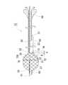
前記カテーテル11にあっては、前記コアワイヤ50を軸方向に操作して前記先端チップ40と前記中空シャフト20との相対距離を変更することにより、前記メッシュ部材30は拡径された状態(図2参照)又は縮径された状態(図1(a)参照)となる。 In the
そして、前記カテーテル11は、図1(a)に示したような、前記メッシュ部材30が縮径された状態で血管内に挿入される。次いで、例えば、前記メッシュ部材30がCTO部分等の所定の位置に達したところで前記コアワイヤ50を操作して、図2に示したような、メッシュ部材30が拡径された状態とする。なお、前記メッシュ部材30を拡径状態とする位置は、状況に合わせて適宜変更可能である。 The
このような前記メッシュ部材30が拡径されることに伴い、前記保護膜70Aの先端側も前記メッシュ部材30の状態変化に追従して拡径され、前記保護膜70A全体が漏斗形状となる(図2参照)。 As the
上述のように前記メッシュ部材30が拡径された状態においては、閉塞物等を前記保護膜70Aの先端72から前記中空シャフト20内へ取り込むことができる。 In the state where the diameter of the
また、当該カテーテル11の反対側からレトロ用ガイドワイヤ80を挿入した場合、図4に示したように、拡径された状態の前記メッシュ部材30の先端部が、レトロ用ガイドワイヤ80が導入される導入部Pとなり、前記レトロ用ガイドワイヤ80が前記導入部Pから前記メッシュ部材30内に挿入される。そして、前記メッシュ部材30内に挿入されたレトロ用ガイドワイヤ80が、漏斗形状となった前記保護膜70Aの案内作用によって前記中空シャフト20内に案内される。その後、レトロ用ガイドワイヤ80は、中空シャフト20のルーメン23及びRXポート21を経由して、体外に回収される。これにより、前記カテーテル11内に案内されたレトロ用ガイドワイヤ80は破損することなく捕獲される。このように、本実施例のカテーテル11は、前記レトロ用ガイドワイヤ80と組み合わせた医療機器として好適に用いることができる。 When the
ここで、本実施例における前記保護膜70Aの先端部は、前記メッシュ部材30を構成する第一素線31にのみ接合されているため、前記メッシュ部材30を拡径する際の自由度が高い。すなわち、前記メッシュ部材30が拡径する際、前記保護膜70Aの先端部は前記メッシュ部材30の第一素線31の動きにのみ追従して径方向に拡張される。したがって、前記メッシュ部材30にあっては、前記第一素線31と前記第二素線32とが互いに前記保護膜70Aの先端部に拘束されてしまう、といった問題がなくなり、前記メッシュ部材30の拡縮が円滑に行われる。 Here, since the tip of the
さらに、前記保護膜70Aの後端部は、前記第一素線31及び前記第二素線32に接合されていないため、前記メッシュ部材30が拡径された際にも径方向に拡張されない。したがって、前記メッシュ部材30の拡径時における保護膜70Aを、容易に、後端方向に向かって縮径した漏斗形状とすることができる。また、このように保護膜70Aの後端部が、前記メッシュ部材30の第一素線31と第二素線32との何れにも接合されていないため、血管内におけるカテーテル11の柔軟性が損なわれない。 Furthermore, since the rear end portion of the
また、上述のように、前記保護膜70Aの後端71は、前記中空シャフト20の先端22の位置まで延びているため、前記メッシュ部材30と前記中空シャフト20との接合部分において、血管内の閉塞物やレトロ用ガイドワイヤ80を中空シャフト20内に漏れなく円滑に誘導することができる。なお、前記保護膜70Aの後端71は、前記中空シャフト20の先端22よりも後端側の位置まで(言い換えると、中空シャフト20のルーメン23まで)延びていてもよい。 Further, as described above, the
〔実施例2〕
実施例2のカテーテル12を、図5に従って説明する。なお、上記実施例1と同様の構成を有するものは同じ符号を付し、説明を省略する。[Example 2]
The
前記カテーテル12にあっては、保護膜70Bの後端73と、前記中空シャフト20の先端22とが、距離dだけ離間し、前記保護膜70Bがメッシュ部材30の後端側の内周を部分的に被覆している。かかる構成にあっては、前記保護膜70Bの後端73が中空シャフト20に拘束されることがないため、前記保護膜70Bが拡縮する際の自由度がさらに向上し、メッシュ部材30の拡縮操作がより一層円滑なものとなる。 In the
〔実施例3〕
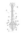
実施例3のカテーテル13を、図6に従って説明する。なお、上記実施例1と同様の構成を有するものは同じ符号を付し、説明を省略する。Example 3
The
前記カテーテル13の保護膜70Aは、前記保護膜70Aの先端部から後端部にわたって、前記メッシュ部材30の第一素線31のみと接着剤75を介して接合されている。すなわち、前記カテーテル13は、実質的に上述した非接合部Qを具備していない。かかる構成にあっても、前記保護膜70Aは、前記メッシュ部材30の第一素線31のみと接合されているため、前記メッシュ部材30の拡縮は円滑に行われる。 The
〔実施例4〕
実施例4のカテーテル14を、図7(a),(b)に従って説明する。なお、上記実施例1と同様の構成を有するものは同じ符号を付し、説明を省略する。Example 4
The
前記カテーテル14は、いわゆる2ルーメン構造であり、中空シャフト20は、内部に中空シャフト20とは別の第二中空シャフト25が挿入されており、中空シャフト20及び第二中空シャフト25は、互いに溶着されている。中空シャフト20と第二中空シャフト25との間に、ルーメン23が形成され、第二中空シャフトの内部に、第二ルーメン24が形成され、この第二ルーメン24にコアワイヤ50が挿通されている。かかる構成にあっては、実施例1〜3のカテーテル11,12,13とは異なり、前記中空シャフト20のルーメン23内に前記コアワイヤ50が挿入されていないため、前記中空シャフト20のルーメン23内において、前記コアワイヤ50と、前記レトロ用ガイドワイヤ80との干渉を好適に回避することができる。また、中空シャフト20のルーメン23に取り込まれた閉塞物等がコアワイヤ50に付着することがないため、閉塞物等により、コアワイヤ50の軸方向への操作が阻害されず、メッシュ部材30の拡縮を円滑に行うことができる。 The
なお、本発明は、上記実施例1〜4以外にも適宜変更可能である。例えば中空シャフト20は、単層構造であってもよいし、複数の層を有した多層構造であってもよい。 In addition, this invention can be suitably changed besides the said Examples 1-4. For example, the
また、メッシュ部材30は、第一素線31及び第二素線32のみで構成されているものに限定されず、他の素線をさらに加えて構成されているものであってもよい。 Moreover, the
また、カテーテル11,12,13,14は、保護膜70A,70Bと第一素線31とが接着剤75を介して接合されている構成に限定されず、例えば保護膜70Aが部分的に第一素線31に溶着されて接合されている構成であってもよい。さらに、カテーテル11,12,13,14において、各部材同士の接合部分についても、接合手段は特に限定されない。 Further, the
また、前記保護膜70A,70Bは、第一素線31に代えて、第二素線32のみに接合されていてもよい。なお、実施例1〜4では、保護膜70A,70Bと第一素線31とは、第一素線31と第二素線32とが交差する交点からずれた位置で接合されていたが、これに限定されない。第一素線31と第二素線32とが交差する交点で、保護膜70A,70Bは、第一素線31と第二素線32とのいずれか一方のみに接合してもよい。 Further, the protective films 70 </ b> A and 70 </ b> B may be joined only to the
また、保護膜70A,70Bは、血管内の閉塞物及びレトロ用ガイドワイヤ80を中空シャフト20内に誘導することができるものであれば、例えばメッシュ部材30よりも目の細かいメッシュ材等によって構成されたものであってもよい。 The
また、前記メッシュ部材30に対して、前記保護膜70A,70Bが軸方向に複数並んで配置されていても勿論よい。 Of course, a plurality of the
なお、レトロ用ガイドワイヤ80は、一般的に使用される公知のものが好適に使用可能である。 In addition, the well-known thing generally used can be used conveniently for the
11,12,13,14 カテーテル
20 中空シャフト
22 先端
25 コアシャフト
30 メッシュ部材
31 第一素線
32 第二素線
35 後端部
40 先端チップ
50 コアワイヤ
70A,70B 保護膜
71 後端11, 12, 13, 14
Claims (2)
Translated fromJapanese前記中空シャフトの先端に接合されたチューブ状のメッシュ部材と、
前記メッシュ部材の先端に接合された先端チップと、
前記先端チップに接合されたコアワイヤと、
を備え、
前記メッシュ部材は、径方向に拡縮するように少なくとも第一素線と第二素線とが互いに編み込まれてなり、前記コアワイヤによって、前記メッシュ部材の拡縮が操作可能とされているカテーテルであって、
前記メッシュ部材の後端側の内周の少なくとも一部を被覆した保護膜を備え、
前記保護膜は、前記第一素線と前記第二素線との何れか一方のみに接合されている
ことを特徴とするカテーテル。A hollow shaft;
A tubular mesh member joined to the tip of the hollow shaft;
A tip chip joined to the tip of the mesh member;
A core wire joined to the tip,
With
The mesh member is a catheter in which at least a first strand and a second strand are knitted together so as to expand and contract in the radial direction, and the expansion and contraction of the mesh member can be operated by the core wire. ,
A protective film covering at least a part of the inner periphery of the rear end side of the mesh member;
The catheter, wherein the protective film is bonded to only one of the first strand and the second strand.
請求項1に記載のカテーテル。The catheter according to claim 1, wherein a rear end of the protective film extends to a position of a front end of the hollow shaft.
Priority Applications (1)
| Application Number | Priority Date | Filing Date | Title |
|---|---|---|---|
| JP2018097014AJP6563075B2 (en) | 2018-05-21 | 2018-05-21 | catheter |
Applications Claiming Priority (1)
| Application Number | Priority Date | Filing Date | Title |
|---|---|---|---|
| JP2018097014AJP6563075B2 (en) | 2018-05-21 | 2018-05-21 | catheter |
Related Parent Applications (1)
| Application Number | Title | Priority Date | Filing Date |
|---|---|---|---|
| JP2015206219ADivisionJP6368291B2 (en) | 2015-10-20 | 2015-10-20 | catheter |
Publications (2)
| Publication Number | Publication Date |
|---|---|
| JP2018126603A JP2018126603A (en) | 2018-08-16 |
| JP6563075B2true JP6563075B2 (en) | 2019-08-21 |
Family
ID=63172742
Family Applications (1)
| Application Number | Title | Priority Date | Filing Date |
|---|---|---|---|
| JP2018097014AActiveJP6563075B2 (en) | 2018-05-21 | 2018-05-21 | catheter |
Country Status (1)
| Country | Link |
|---|---|
| JP (1) | JP6563075B2 (en) |
Family Cites Families (6)
| Publication number | Priority date | Publication date | Assignee | Title |
|---|---|---|---|---|
| CA2161640C (en)* | 1993-04-29 | 2005-04-12 | Thomas V. Ressemann | Expandable intravascular occlusion material removal device |
| US20020138094A1 (en)* | 1999-02-12 | 2002-09-26 | Thomas Borillo | Vascular filter system |
| US20010031981A1 (en)* | 2000-03-31 | 2001-10-18 | Evans Michael A. | Method and device for locating guidewire and treating chronic total occlusions |
| JP2004097807A (en)* | 2002-08-20 | 2004-04-02 | Nipro Corp | Thrombus capturing catheter |
| JP4327573B2 (en)* | 2003-12-02 | 2009-09-09 | 株式会社パイオラックスメディカルデバイス | Stent graft |
| WO2009124288A1 (en)* | 2008-04-04 | 2009-10-08 | Reverse Medical Corporation | Multi-utilitarian microcatheter system and method of use |
- 2018
- 2018-05-21JPJP2018097014Apatent/JP6563075B2/enactiveActive
Also Published As
| Publication number | Publication date |
|---|---|
| JP2018126603A (en) | 2018-08-16 |
Similar Documents
| Publication | Publication Date | Title |
|---|---|---|
| JP6368291B2 (en) | catheter | |
| US11517339B2 (en) | Flexible intravascular treatment devices and associated systems and methods of use | |
| US11213307B2 (en) | Retrieval systems and methods for use thereof | |
| JP5746014B2 (en) | Rapid exchange catheter with tear-resistant guidewire shaft | |
| JP5770105B2 (en) | Catheter assembly | |
| JP6296580B1 (en) | Catheter and balloon catheter | |
| JP5164283B2 (en) | Balloon catheter | |
| JP7000417B2 (en) | Medical long body and medical equipment set | |
| CN105963848B (en) | Balloon catheter | |
| JP2021137574A (en) | Catheter proximal junction | |
| EP2762192A1 (en) | Balloon catheter | |
| JP2013022187A (en) | Balloon catheter | |
| JP6972315B2 (en) | catheter | |
| JP2012005704A (en) | Balloon catheter | |
| JP6563075B2 (en) | catheter | |
| JP2012045043A (en) | Medical appliance | |
| WO2007034639A1 (en) | Stent delivery catheter | |
| JP2020062318A (en) | catheter | |
| JP6811511B2 (en) | Catheter and balloon catheter | |
| JP2023129895A (en) | catheter | |
| JP7598822B2 (en) | Foreign object capture device and foreign object capture system | |
| CN113056243A (en) | Medical stent and stent delivery device | |
| JP2019150317A (en) | Guide wire | |
| JP7021464B2 (en) | Separator and suction system | |
| JP2022059511A (en) | catheter |
Legal Events
| Date | Code | Title | Description |
|---|---|---|---|
| A621 | Written request for application examination | Free format text:JAPANESE INTERMEDIATE CODE: A621 Effective date:20180614 | |
| TRDD | Decision of grant or rejection written | ||
| A01 | Written decision to grant a patent or to grant a registration (utility model) | Free format text:JAPANESE INTERMEDIATE CODE: A01 Effective date:20190709 | |
| A61 | First payment of annual fees (during grant procedure) | Free format text:JAPANESE INTERMEDIATE CODE: A61 Effective date:20190723 | |
| R150 | Certificate of patent or registration of utility model | Ref document number:6563075 Country of ref document:JP Free format text:JAPANESE INTERMEDIATE CODE: R150 | |
| R250 | Receipt of annual fees | Free format text:JAPANESE INTERMEDIATE CODE: R250 | |
| R250 | Receipt of annual fees | Free format text:JAPANESE INTERMEDIATE CODE: R250 | |
| R250 | Receipt of annual fees | Free format text:JAPANESE INTERMEDIATE CODE: R250 | |
| R250 | Receipt of annual fees | Free format text:JAPANESE INTERMEDIATE CODE: R250 |