JP6557274B2 - Component mounting position guidance device, component mounting position guidance system, and component mounting position guidance method - Google Patents
Component mounting position guidance device, component mounting position guidance system, and component mounting position guidance methodDownload PDFInfo
- Publication number
- JP6557274B2 JP6557274B2JP2017072132AJP2017072132AJP6557274B2JP 6557274 B2JP6557274 B2JP 6557274B2JP 2017072132 AJP2017072132 AJP 2017072132AJP 2017072132 AJP2017072132 AJP 2017072132AJP 6557274 B2JP6557274 B2JP 6557274B2
- Authority
- JP
- Japan
- Prior art keywords
- machine
- mounting position
- image
- guidance
- component mounting
- Prior art date
- Legal status (The legal status is an assumption and is not a legal conclusion. Google has not performed a legal analysis and makes no representation as to the accuracy of the status listed.)
- Active
Links
Images


Classifications
- G—PHYSICS
- G09—EDUCATION; CRYPTOGRAPHY; DISPLAY; ADVERTISING; SEALS
- G09B—EDUCATIONAL OR DEMONSTRATION APPLIANCES; APPLIANCES FOR TEACHING, OR COMMUNICATING WITH, THE BLIND, DEAF OR MUTE; MODELS; PLANETARIA; GLOBES; MAPS; DIAGRAMS
- G09B19/00—Teaching not covered by other main groups of this subclass
- G—PHYSICS
- G05—CONTROLLING; REGULATING
- G05B—CONTROL OR REGULATING SYSTEMS IN GENERAL; FUNCTIONAL ELEMENTS OF SUCH SYSTEMS; MONITORING OR TESTING ARRANGEMENTS FOR SUCH SYSTEMS OR ELEMENTS
- G05B19/00—Programme-control systems
- G05B19/02—Programme-control systems electric
- G05B19/04—Programme control other than numerical control, i.e. in sequence controllers or logic controllers
- G—PHYSICS
- G08—SIGNALLING
- G08B—SIGNALLING OR CALLING SYSTEMS; ORDER TELEGRAPHS; ALARM SYSTEMS
- G08B5/00—Visible signalling systems, e.g. personal calling systems, remote indication of seats occupied
- G08B5/22—Visible signalling systems, e.g. personal calling systems, remote indication of seats occupied using electric transmission; using electromagnetic transmission
- G—PHYSICS
- G09—EDUCATION; CRYPTOGRAPHY; DISPLAY; ADVERTISING; SEALS
- G09B—EDUCATIONAL OR DEMONSTRATION APPLIANCES; APPLIANCES FOR TEACHING, OR COMMUNICATING WITH, THE BLIND, DEAF OR MUTE; MODELS; PLANETARIA; GLOBES; MAPS; DIAGRAMS
- G09B5/00—Electrically-operated educational appliances
- G09B5/06—Electrically-operated educational appliances with both visual and audible presentation of the material to be studied
- G09B5/065—Combinations of audio and video presentations, e.g. videotapes, videodiscs, television systems
- H—ELECTRICITY
- H04—ELECTRIC COMMUNICATION TECHNIQUE
- H04L—TRANSMISSION OF DIGITAL INFORMATION, e.g. TELEGRAPHIC COMMUNICATION
- H04L41/00—Arrangements for maintenance, administration or management of data switching networks, e.g. of packet switching networks
- H04L41/06—Management of faults, events, alarms or notifications
- H04L41/0631—Management of faults, events, alarms or notifications using root cause analysis; using analysis of correlation between notifications, alarms or events based on decision criteria, e.g. hierarchy, tree or time analysis
Landscapes
- Engineering & Computer Science (AREA)
- Physics & Mathematics (AREA)
- General Physics & Mathematics (AREA)
- Business, Economics & Management (AREA)
- Educational Administration (AREA)
- Educational Technology (AREA)
- Theoretical Computer Science (AREA)
- Multimedia (AREA)
- Entrepreneurship & Innovation (AREA)
- Electromagnetism (AREA)
- Computer Networks & Wireless Communication (AREA)
- Signal Processing (AREA)
- Automation & Control Theory (AREA)
- Supply And Installment Of Electrical Components (AREA)
- Numerical Control (AREA)
- General Factory Administration (AREA)
- Automatic Assembly (AREA)
- Controls And Circuits For Display Device (AREA)
Description
Translated fromJapanese本発明は、機械を構成する部品の実装位置を表示装置に表示させる、部品実装位置ガイダンス装置、部品実装位置ガイダンスシステム、及び部品実装位置ガイダンス方法に関する。 The present invention relates to a component mounting position guidance device, a component mounting position guidance system, and a component mounting position guidance method that display a mounting position of components constituting a machine on a display device.
従来、構造が複雑な機械においては、アラームが発生し、故障部品が特定された場合でも、故障部品の実装位置を特定することが難しい。この点、特許文献1には、車の故障箇所を特定するため、ユーザが所有している車両と同じ車両の図面を表示し、ガイダンスを利用しながら故障箇所を特定する技術が記載されている。 Conventionally, in a machine having a complicated structure, it is difficult to specify a mounting position of a failed part even when an alarm is generated and the failed part is specified. In this regard,
引用文献1に係る技術において引用されている図は、一般的に車を運転している人であれば当然知っていると思われる内部構造から説明されている。しかし、メーカによって構造が大きく変わると共に構造が複雑な工作機械等の機械の場合、実際に操作しているオペレータは、通常時に操作する機械の場所は熟知しているが、機械の側面や背面の構造には不慣れなことが多い。このため、故障部品や故障部品を含むユニットが特定されたとしても、これら部品やユニットが側面や背面にある場合に、部品やユニットの実装位置を把握することが難しいという課題がある。 The figure quoted in the technology according to the cited
本発明は、上記課題に鑑みてなされたものであり、オペレータがいつも操作している機械位置から、故障箇所の実装位置へガイダンスする部品実装位置ガイダンス装置を提供することを目的とする。 The present invention has been made in view of the above problems, and an object of the present invention is to provide a component mounting position guidance device that provides guidance from a machine position that is always operated by an operator to a mounting position of a failure location.
(1) 本発明によれば、制御部(例えば、後述の「制御部11」)を備え、前記制御部は、機械(例えば、後述の「機械30」)を構成する部品ごとに、機械の所定位置から、前記部品の実装位置に至るまでの1つ以上の位置情報を順序付けした位置順序データを取得する位置順序データ取得部(例えば、後述の「位置順序データ取得部12」)と、前記位置順序データ取得部により取得した前記位置順序データに基づいて、前記機械の所定位置を示す画像から前記部品の実装位置を示す画像に至るまでの前記1つ以上の位置情報を示す画像を順番に表示装置(例えば、後述の「表示部20」)に表示させるガイダンス表示制御部(例えば、後述の「ガイダンス表示制御部13」)と、を備える部品実装位置ガイダンス装置(例えば、後述の「部品実装位置ガイダンス装置10」)が提供される。 (1) According to the present invention, a control unit (for example, “
(2) (1)に記載の部品実装位置ガイダンス装置(例えば、後述の「部品実装位置ガイダンス装置10」)において、前記位置順序データは、さらに、前記位置順序データを構成する各位置情報と前記機械の外形図及び/又は前記機械の内部構造図の画像データとの対応関係を含み、前記ガイダンス表示制御部(例えば、後述の「ガイダンス表示制御部13」)は、前記対応関係に基づいて、前記機械の所定位置を示す画像から前記部品の実装位置を示す画像に至るまでの前記1つ以上の位置情報を示す画像を順番に表示装置に表示させることが好ましい。 (2) In the component mounting position guidance device according to (1) (for example, “component mounting
(3) (1)又は(2)に記載の部品実装位置ガイダンス装置(例えば、後述の「部品実装位置ガイダンス装置10」)において、前記ガイダンス表示制御部(例えば、後述の「ガイダンス表示制御部13)は、さらに、前記機械がアラームを出力した場合に、前記アラームと前記部品との対応関係に基づいて、前記機械の所定位置を示す画像から前記アラームに対応する部品の実装位置を示す画像に至るまでの前記1つ以上の位置情報を示す画像を順番に前記表示装置に表示させることが好ましい。 (3) In the component mounting position guidance device described in (1) or (2) (for example, “component mounting
(4) (2)又は(3)に記載の部品実装位置ガイダンス装置(例えば、後述の「部品実装位置ガイダンス装置10」)において、前記機械の所定位置を示す画像は、前記機械の操作盤を見る地点から前記機械を見た外形図であることが好ましい。 (4) In the component mounting position guidance device according to (2) or (3) (for example, “component mounting
(5) (1)〜(4)に記載の部品実装位置ガイダンス装置(例えば、後述の「部品実装位置ガイダンス装置10」)において、前記ガイダンス表示制御部(例えば、後述の「ガイダンス表示制御部13」)は、コメント付きの静止画像を順番に表示装置(例えば、後述の「表示部20」)に表示させることが好ましい。 (5) In the component mounting position guidance device (for example, “component mounting
(6) (1)〜(5)に記載の部品実装位置ガイダンス装置(例えば、後述の「部品実装位置ガイダンス装置10」)において、前記ガイダンス表示制御部(例えば、後述の「ガイダンス表示制御部13」)は、音声付きの動画を順番に表示装置(例えば、後述の「表示部20」)に表示させることが好ましい。 (6) In the component mounting position guidance device (for example, “component mounting
(7) (1)〜(6)に記載の部品実装位置ガイダンス装置(例えば、後述の「部品実装位置ガイダンス装置10」)において、前記位置順序データを記憶する記憶装置(例えば、後述の「記憶部14」)から、前記位置順序データを取得することが好ましい。 (7) In the component mounting position guidance device (for example, “component mounting
(8) 本発明によれば、(1)〜(7)のいずれか1項に記載の部品実装位置ガイダンス装置(例えば、後述の「部品実装位置ガイダンス装置10」)を備える機械(例えば、後述の「機械30」)が提供される。 (8) According to the present invention, a machine (for example, described later) including the component mounting position guidance device (for example, “component mounting
(9) 本発明によれば、(1)〜(7)のいずれか1項に記載の部品実装位置ガイダンス装置(例えば、後述の「部品実装位置ガイダンス装置10」)と、通信可能に接続された一つ以上の前記機械(例えば、後述の「機械30」)とを備える、部品実装位置ガイダンスシステム(例えば、後述の「部品実装位置ガイダンスシステム1」)が提供される。 (9) According to the present invention, communication with the component mounting position guidance device according to any one of (1) to (7) (for example, “component mounting
(10) 本発明によれば、機械(例えば、後述の「機械30」)を構成する部品ごとに、機械の所定位置から、前記部品の実装位置に至るまでの1つ以上の位置情報を順序付けした位置順序データを取得する位置順序データ取得工程と、前記位置順序データ取得工程により取得した前記位置順序データに基づいて、前記機械の所定位置を示す画像から前記部品の実装位置を示す画像に至るまでの前記1つ以上の位置情報を示す画像を順番に表示装置に表示させる工程と、を有する部品実装位置ガイダンス方法が提供される。 (10) According to the present invention, one or more pieces of position information from a predetermined position of the machine to a mounting position of the part are ordered for each part constituting the machine (for example, “
本発明によれば、構造が複雑な機械を構成する部品やユニットの、機械内における実装位置を、ユーザが容易に把握することが可能となる。とりわけ、本発明の部品実装位置ガイダンス装置は、オペレータがいつも操作している機械位置から、故障箇所の実装位置へガイダンスするので、オペレータは短時間に故障箇所の実装位置を特定することができる。 According to the present invention, it becomes possible for a user to easily grasp the mounting position of a part or unit constituting a machine having a complicated structure in the machine. In particular, the component mounting position guidance apparatus according to the present invention provides guidance from the machine position that is always operated by the operator to the mounting position of the failure location, so that the operator can specify the mounting location of the failure location in a short time.
〔第1実施形態〕
以下、図1〜図6を参照しながら、本発明の第1実施形態について詳述する。
図1は、本実施形態に係る部品実装位置ガイダンスシステム1の全体構成図である。部品実装位置ガイダンスシステム1は、部品実装位置ガイダンス装置10と機械30とを備える。部品実装位置ガイダンス装置10と機械30とは、1対1の組とされて、通信可能に接続されている。部品実装位置ガイダンス装置10と機械30とは、接続インタフェースを介して直接接続されても、またLAN(Local Area Network)等のネットワークを介して接続されてもよい。[First Embodiment]
Hereinafter, the first embodiment of the present invention will be described in detail with reference to FIGS.
FIG. 1 is an overall configuration diagram of a component mounting
部品実装位置ガイダンス装置10は、機械30を構成する部品ごとに、機械30の所定位置からその部品の実装位置までの位置情報を示す画像を、後述の表示部15に順番に表示させる装置である。 The component mounting
機械30は、工場内に設置された産業用ロボットや工作機械等といった装置である。機械30は、演算処理装置や記憶装置や、オペレータによる入出力装置等を備え、ソフトウェアにより制御することができる。なお、図1中では、一つの機能ブロックで機械30を表しているが、機械30は、産業用ロボット又は工作機械と、これらを制御する数値制御装置との組み合わせといった複数の装置の組み合わせであってもよい。なお、工作機械としては、例えば、旋盤、フライス盤、放電加工機、研削盤、マシニングセンタ、レーザー加工機等が挙げられる。 The
図2は、部品実装位置ガイダンス装置10の全体構成図である。部品実装位置ガイダンス装置10は、制御部11、記憶部14、入力部19、表示部20を備える。 FIG. 2 is an overall configuration diagram of the component mounting
制御部11は、部品実装位置ガイダンス装置10の全体を制御する部分であり、各種プログラムを、ROM、RAM、フラッシュメモリ又はハードディスク(HDD)等の記憶領域から適宜読み出して実行することにより、本実施形態における各種機能を実現している。制御部11は、CPUであってよい。制御部11は、位置順序データ取得部12とガイダンス表示制御部13とを備える。位置順序データ取得部12とガイダンス表示制御部13の機能の詳細については、後述する。
また、制御部11は、それ以外にも、部品実装位置ガイダンス装置10の全体を制御するための機能ブロック、通信を行うための機能ブロックといった一般的な機能ブロックを備える。ただし、これらの一般的な機能ブロックについては当業者によく知られているので図示及び説明を省略する。The
In addition, the
記憶部14は、位置順序データとして、位置順序テーブル15、位置画像対応テーブル16、アラーム部品対応テーブル17、画像ファイル18を記憶する。以下、図3A〜図3C、図4A〜図4Iを参照しながら、各テーブル、及び画像ファイルの内容について詳述する。 The
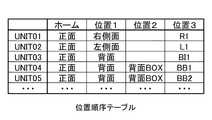
図3Aは、例えば、機械の操作盤を見る地点から機械を眺めた正面である所定位置から、機械30を構成する各部品の実装位置に至るまで、どのような順序の位置情報でガイダンスするかを定義する位置順序テーブル15を示す。具体的には、図3Aの位置順序テーブル15は、各部品ごと(UNIT01〜UNIT05)に、上記の「所定位置」に対応する「ホーム」の画像を表示した後、「位置1」→「位置2」→「位置3」(実装位置)の順で、位置nを示す画像を表示する順序を定義する。 In FIG. 3A, for example, in what order position information is guided from a predetermined position which is a front view of the machine from a point where the machine operation panel is viewed to a mounting position of each component constituting the
例えば、第1行目のデータであれば、「UNIT01」という部品の実装位置を、後述の表示部20で表示する際、最初に「ホーム」として「正面」の画像を示し、2番目に「位置1」として「右側面」の画像を示し、3番目に「位置3」(UNIT01の実装位置)として「右側面」の画像の中の「R1」という箇所を示すことを定義する。
また、例えば、第4行目のデータであれば、「UNIT04」という部品の実装位置を表示部20で表示する際、最初に「ホーム」として「正面」の画像を示し、2番目に「位置1」として「背面」の画像を示し、3番目に「位置2」として「背面BOX」の画像を示し、4番目に「位置3」(UNIT04の実装位置)として、「BB1」の画像を示すことを定義する。For example, in the case of the data in the first row, when displaying the mounting position of the component “UNIT01” on the
Further, for example, in the case of the data in the fourth row, when displaying the mounting position of the component “UNIT04” on the
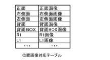
図3Bは、図3Aの位置順序テーブル15に記載された位置情報の各々と、後述の図4A〜図4Iで示される各画像データとの対応関係を定義する位置画像対応テーブル16を示す。
例えば、図3Bの位置画像対応テーブル16中1行目のデータにおいて、図3Aの位置順序テーブル15に記載の「正面」という位置情報は、後述の図4Aで示される「正面画像」の画像データに対応することが定義される。
また、図3Bの位置画像対応テーブル16中2行目のデータにおいて、図3Aの位置順序テーブル15に記載の「右側面」という位置情報は、後述の図4Bで示される「右側面画像」の画像データに対応することが示される。
また、図3Bの位置画像対応テーブル16中3行目のデータにおいて、図3Aの位置順序テーブル15に記載の「左側面」という位置情報は、後述の図4Cで示される「左側面画像」の画像データに対応することが示される。
また、図3Bの位置画像対応テーブル16中4行目のデータにおいて、図3Aの位置順序テーブル15に記載の「背面」という位置情報は、後述の図4Dで示される「背面画像」の画像データに対応することが定義される。
また、図3Bの位置画像対応テーブル16中5行目のデータにおいて、図3Aの位置順序テーブル15に記載の「背面BOX」という位置情報は、後述の図4Eで示される「背面BOX画像」に対応することが定義される。
また、図3Bの位置画像対応テーブル16中6行目のデータにおいて、図3Aの位置順序テーブル15に記載の「R1」という位置情報は、後述の図4Fで示される「R1画像」の画像データに対応することが示される。
また、図3Bの位置画像対応テーブル16中7行目のデータにおいて、図3Aの位置順序テーブル15に記載の「L1」という位置情報は、後述の図4Gで示される「L1画像」の画像データに対応することが示される。
また、図3Bには示されていないが、図3Aの位置順序テーブル15に記載の「BB1」という位置情報は、後述の図4Iの画像を用いて示される「BB1画像」に対応することが定義される。FIG. 3B shows a position image correspondence table 16 that defines a correspondence relationship between each piece of position information described in the position order table 15 of FIG. 3A and each image data shown in FIGS. 4A to 4I described later.
For example, in the data of the first row in the position image correspondence table 16 in FIG. 3B, the position information “front” described in the position order table 15 in FIG. 3A is the image data of “front image” shown in FIG. Is defined to correspond to
Further, in the data of the second row in the position image correspondence table 16 in FIG. 3B, the position information “right side” described in the position order table 15 in FIG. 3A is the “right side image” shown in FIG. It is shown that it corresponds to image data.
Further, in the data of the third row in the position image correspondence table 16 of FIG. 3B, the position information “left side” described in the position order table 15 of FIG. 3A is the “left side image” shown in FIG. It is shown that it corresponds to image data.
Further, in the data of the fourth row in the position image correspondence table 16 of FIG. 3B, the position information “back” described in the position order table 15 of FIG. 3A is the image data of “back image” shown in FIG. Is defined to correspond to
Further, in the data of the fifth row in the position image correspondence table 16 of FIG. 3B, the position information “back BOX” described in the position order table 15 of FIG. 3A is stored in “back BOX image” shown in FIG. 4E described later. Corresponding is defined.
3B, the position information “R1” described in the position order table 15 in FIG. 3A is the image data of “R1 image” shown in FIG. 4F described later. Corresponding to.
3B, the position information “L1” described in the position order table 15 in FIG. 3A is the image data of “L1 image” shown in FIG. 4G described later. Corresponding to.
Although not shown in FIG. 3B, the position information “BB1” described in the position order table 15 in FIG. 3A may correspond to “BB1 image” shown using the image in FIG. 4I described later. Defined.
なお、位置順序テーブル15において、「UNIT01」〜「UNIT03」の「位置2」の欄がブランクとなっているが、これは、「位置3」で示される符号が、「位置1」に対応する画像に含まれているためである。例えば、「UNIT01」であれば、「位置3」の欄で、後述の図4Fに示す「R1画像」を示すことが定義されるが、この「R1画像」は、後述の図4Fに示されるように、「位置1」に対応する「右側面画像」(後述の図4B)に符号を付加したものであり、「位置2」の欄で改めて「右側面画像」の表示を定義する必要はないため、「位置2」の欄はブランクとなっている。「UNIT02」及び「UNIT03」の「位置2」の欄がブランクとなっている理由も同様である。 In the position order table 15, the “
図3Cは、機械30が発する各アラームと、機械30を構成する部品の部品番号との対応関係を定義するアラーム部品対応テーブル17を示す。例えば、図3Cのアラーム部品対応テーブル17中1行目のデータにおいて、「AL(1)」というアラームは、部品番号「UNIT03」の部品に対応することが定義される。 FIG. 3C shows an alarm part correspondence table 17 that defines a correspondence relationship between each alarm generated by the
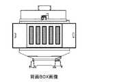
図4A〜図4Iは、画像ファイル18に含まれる、各位置情報に対応する画像データを示す。図4Aは、機械30の正面画像である。図4Bは、機械30の右側面画像である。図4Cは、機械30の左側面画像である。図4Dは、機械30の背面画像である。図4Eは、機械30の背面に設置された各BOXを示す背面BOX画像である。図4Fは、位置「R1」を示す画像である。図4Gは、位置「L1」を示す画像である。図4Hは、位置「BI1」を示す画像である。図4Iは、背面BOX画像に示される各BOXの符号をまとめて示す画像である。具体的には、図4Iは、背面BOXが、左から順に、「BB1」、「BB2」、「BB3」、「BB4」、「BB5」の符号で示されることを示す。実際に図4Iの画像を用いる際は、符号「BB1」のみを示した「BB1画像」、符号「BB2」のみを示した「BB2画像」、符号「BB3」のみを示した「BB3画像」、符号「BB4」の身を示した「BB4画像」、又は、符号「BB5」のみを示した「BB5画像」として用いる。 4A to 4I show image data corresponding to each position information included in the
なお、各画像データのうち、図3Aの位置順序テーブル15の「ホーム」の位置情報に対応する画像は、機械30の操作盤を見る地点から機械30を見た外形図であることが好ましい。 Of the image data, the image corresponding to the “home” position information in the position order table 15 of FIG. 3A is preferably an outline view of the
次に、制御部11について説明する。
位置順序データ取得部12は、機械30を構成する部品ごとに、機械の所定位置から、当該部品の実装位置に至るまでの1つ以上の位置情報を順序付けした位置順序データを取得するために、位置順序テーブル15、位置画像対応テーブル16、アラーム部品対応テーブル17及び画像ファイル18を参照する。より具体的には、機械30がアラームを発すると、位置順序データ取得部12は、アラーム部品対応テーブル17を参照することにより、アラームに対応する部品番号を特定し、位置順序テーブル15を参照することにより、部品番号に対応する位置順序を特定し、位置画像対応テーブル16を参照することにより、位置順序に含まれる各々の位置情報に対応する画像を特定する。Next, the
The position order data acquisition unit 12 acquires, for each part constituting the
ガイダンス表示制御部13は、位置順序データ取得部12が取得した位置順序データに基づいて、機械の所定位置を示す画像から、当該部品の実装位置を示す画像に至るまでの1つ以上の位置情報を示す画像を、順番に、表示部20に表示させる。より具体的には、ガイダンス表示制御部13は、位置順序データ取得部12によって特定された、位置順序に含まれる各々の位置情報に対応する画像を、表示部20に表示させる。 The guidance
入力部19は、部品実装位置ガイダンス装置10のオペレータが、機械30を構成する部品の部品番号を入力するために用いる装置である。 The
表示部20は、上記のガイダンス表示制御部13からの制御により、機械の所定位置を示す画像から、部品の実装位置を示す画像に至るまでの1つ以上の位置情報を示す画像を表示するために用いる装置である。 The
次に、部品実装位置ガイダンス装置10の処理フローについて説明する。
図5は、部品実装位置ガイダンス装置10の動作を示すフローチャートである。
図5を参照すると、ステップS11において、アラームが発生した場合(S11:YES)には、処理はステップS12に移行する。アラームが発生していない場合(S11:NO)には、処理はステップS11に戻る。Next, a processing flow of the component mounting
FIG. 5 is a flowchart showing the operation of the component mounting
Referring to FIG. 5, if an alarm is generated in step S11 (S11: YES), the process proceeds to step S12. If no alarm has occurred (S11: NO), the process returns to step S11.
ステップS12において、位置順序データ取得部12は、記憶部14からアラーム部品対応テーブル17を取得し、アラーム部品対応テーブル17を参照することにより、アラームに対応する部品番号を特定する。 In step S12, the position order data acquisition unit 12 acquires the alarm component correspondence table 17 from the
ステップS13において、位置順序データ取得部12は、記憶部14から位置順序テーブル15を取得し、位置順序テーブル15を参照することにより、ステップS12において特定された部品番号に対応する位置順序を特定する。 In step S13, the position order data acquisition unit 12 acquires the position order table 15 from the
ステップS14において、位置順序データ取得部12は、記憶部14から位置画像対応テーブル16を取得し、位置画像対応テーブル16を参照することにより、ステップS13において特定された位置順序のうち、「ホーム」の位置に対応する画像を特定する。さらに、ガイダンス表示制御部13は、位置順序データ取得部12により特定された画像を、表示部20に表示させる。 In step S <b> 14, the position order data acquisition unit 12 acquires the position image correspondence table 16 from the
ステップS15において、位置順序データ取得部12は、位置画像対応テーブル16を参照することにより、ステップS13において特定された位置順序のうち、「位置1」の位置に対応する画像を特定し、ガイダンス表示制御部13は、位置順序データ取得部12により特定された画像を、表示部20に表示させる。 In step S15, the position order data acquisition unit 12 refers to the position image correspondence table 16 to identify an image corresponding to the position of “
ステップS16において、位置順序データ取得部12は、位置画像対応テーブル16を参照することにより、ステップS13において特定された位置順序のうち、「位置2」の位置に対応する画像を特定し、ガイダンス表示制御部13は、位置順序データ取得部12により特定された画像を、表示部20に表示させる。 In step S <b> 16, the position order data acquisition unit 12 refers to the position image correspondence table 16 to identify an image corresponding to the position “
ステップS17において、位置順序データ取得部12は、位置画像対応テーブル16を参照することにより、ステップS13において特定された位置順序のうち、「位置3」の位置に対応する画像を特定し、ガイダンス表示制御部13は、位置順序データ取得部12により特定された画像を、表示部20に表示させ、動作フローを終了する。 In step S <b> 17, the position order data acquisition unit 12 refers to the position image correspondence table 16 to identify an image corresponding to the position “
なお、上記の動作フロー中、ステップS14〜S17において、ガイダンス表示制御部13が、1つ以上の位置情報を示す画像を順番に表示部20に表示させる際、コメント付きの静止画像を順番に表示部20に表示させてもよい。あるいは、ガイダンス表示制御部13は、音声付きの動画を順番に表示部20に表示させてもよい。 In the above operation flow, when the guidance
次に、アラームが「AL(3)」である場合における、部品実装位置ガイダンス装置10の具体的な動作と、表示画面の遷移について、図6を参照しながら説明する。 Next, a specific operation of the component mounting
アラームが「AL(3)」である場合、位置順序データ取得部12は、アラーム部品対応テーブル17から、アラーム「AL(3)」が部品番号「UNIT05」に対応することを特定する。次に、位置順序データ取得部12は、位置順序テーブル15から、部品番号「UNIT05」に対応する位置順序が、「ホーム:正面」→「位置1:背面」→「位置2:背面BOX」→「位置3:BB2」であることを特定する。 When the alarm is “AL (3)”, the position sequence data acquisition unit 12 specifies from the alarm component correspondence table 17 that the alarm “AL (3)” corresponds to the component number “UNIT05”. Next, the position order data acquisition unit 12 determines from the position order table 15 that the position order corresponding to the part number “UNIT05” is “home: front” → “position 1: back” → “position 2: back BOX” → Specify “Position 3: BB2”.
次に、位置順序データ取得部12は、位置画像対応テーブル16から、「正面」に対応する画像が「正面画像」であり、「背面」に対応する画像が「背面画像」であり、「背面BOX」に対応する画像が「背面BOX画像」であり、「BB2」に対応する画像が「BB2画像」であることを特定する。ガイダンス表示制御部13は、これに従い、図6に示すように、最初に図4Aの正面画像を表示させ、2番目に図4Dの背面画像を表示させ、3番目に図4Eの背面BOX画像を表示させ、最後に図4Iの画像を、符号が「BB2」であることを示す画像として表示させる。 Next, from the position image correspondence table 16, the position sequence data acquisition unit 12 has the “front image” as the image corresponding to “front”, the “rear image” as the image corresponding to “rear”, and the “rear image”. It is specified that the image corresponding to “BOX” is the “rear BOX image” and the image corresponding to “BB2” is the “BB2 image”. In accordance with this, the guidance
なお、上記の実施形態においては、機械30でアラームが発生した際、部品実装位置ガイダンス装置10は、アラームと対応する部品の実装位置をガイダンスする構成としたが、これには限定されない。例えば、アラームが未発生の段階での定期メンテナンス時において、機械30を構成する部品を補修する必要が発生した場合に、保守員が入力部19から部品の部品番号を入力し、部品実装位置ガイダンス装置10は、この部品番号に対応する位置順序データを特定することにより、部品の実装位置をガイダンスすることができる。 In the above embodiment, when the alarm is generated in the
〔第1実施形態の効果〕
本実施形態によれば、部品実装位置ガイダンス装置10の制御部11は、位置順序データ取得部12とガイダンス表示制御部13とを備える。また、位置順序データ取得部12は、記憶部14から、位置順序テーブル15、位置画像対応テーブル16、アラーム部品対応テーブル17、画像ファイル18を参照して位置順序データを取得する。また、ガイダンス表示制御部13は、位置順序データ取得部12が取得した位置順序データに基づいて、機械30の所定位置を示す画像から部品の実装位置を示す画像に至るまでの1つ以上の位置情報を示す画像を順番に表示部20に表示させる。
これにより、部品実装位置ガイダンス装置10は、オペレータがいつも操作している機械位置から、故障箇所の実装位置へガイダンスするので、オペレータは、短時間に故障箇所の実装位置を特定することができる。[Effects of First Embodiment]
According to the present embodiment, the
As a result, the component mounting
また、位置順序データは、各位置情報と機械30の外形図及び/又は機械30の内部構造図の画像データとの対応関係を含むため、1つ以上の位置情報を表示する際、画像を用いて表示することが可能となる。
これにより、機械30のオペレータは、各位置情報に対応する画像から、部品の実装位置をより容易に認識することが可能となる。Further, since the position order data includes a correspondence relationship between each position information and the image data of the outline drawing of the
Thereby, the operator of the
また、機械30がアラームを出力した場合に、部品実装位置ガイダンス装置10は、アラーム部品対応テーブル17を参照して取得した当該アラームと部品との対応関係に基づいて、機械30の所定位置を示す画像から、当該アラームに対応する部品の実装位置を示す画像に至るまでの1つ以上の位置情報を示す画像を表示部20に表示させる。
これにより、機械30に故障が発生した場合に、機械30のオペレータは、故障部品の実装位置を容易に認識することが可能となる。In addition, when the
Thereby, when a failure occurs in the
また、上記の機械30の所定位置を示す画像は、例えば、機械30の操作盤を見る地点から機械30を見た外形図である。
これにより、オペレータは、短時間に故障部品の実装位置を特定することができる。The image showing the predetermined position of the
Thereby, the operator can specify the mounting position of the failed component in a short time.
また、ガイダンス表示制御部13は、コメント付きの静止画像を順番に表示部20に表示させたり、音声付きの動画を順番に表示部20に表示させたりすることが可能である。
これにより、機械30のオペレータは、容易に部品の実装位置を特定することができる。Further, the guidance
Thereby, the operator of the
〔第2実施形態〕
本発明の第2実施形態では、第1実施形態における機械30が、部品実装位置ガイダンス装置10を、自身の一部として備える。以下、図7を参照しながら、本発明の第2実施形態について説明する。
図7は、本発明の第2実施形態に係る機械40の全体構成図である。機械40は、制御装置41、記憶装置42、表示装置43、制御盤44、駆動装置45を備える。[Second Embodiment]
In the second embodiment of the present invention, the
FIG. 7 is an overall configuration diagram of a
制御装置41は、その一部として、第1実施形態に係る部品実装位置ガイダンス装置10の制御部11と同様に、位置順序データ取得部12とガイダンス表示制御部13とを備える。また、この制御装置41で、駆動装置45のアラームを検出する。さらに、制御装置41は、それ以外にも、駆動装置45を制御するための機能ブロック、通信を行うための機能ブロック、ユーザからの操作を受け付けるための機能ブロック、といった一般的な機能ブロックを備える。ただし、これらの一般的な機能ブロックについては当業者によく知られているので図示及び説明を省略する。 The
記憶装置42は、第1実施形態に係る部品実装位置ガイダンス装置10の記憶部14と同様に、位置順序テーブル15、位置画像対応テーブル16、アラーム部品対応テーブル17、及び画像ファイル18を記憶する。 The
表示装置43は、第1実施形態に係る部品実装位置ガイダンス装置10の表示部20と同一の機能を有する。具体的には、ガイダンス表示制御部13からの制御により、機械の所定位置を示す画像から、部品の実装位置を示す画像に至るまでの1つ以上の位置情報を示す画像を表示する。 The
制御盤44は、後述の駆動装置45の動作を電気制御するために用いられる制御盤であり、例えば、電磁開閉器、インバータ、サーボドライバ、サーボアンプ、セレクタスイッチ、シーケンサ等を含んでもよい。 The
駆動装置45は、機械40で切削や加工等の作業をする際に駆動される装置であり、例えば、主軸モータ及び送り軸モータを含んでもよい。 The
機械40においては、オペレータが実際に切削や加工等の作業をしている最中に、アラームが発生した場合、制御装置41が当該アラームに対応する部品番号を特定し、この部品番号に対応する位置順序データを用いて、表示装置43に、機械40の所定位置を示す画像から故障部品の実装位置を示す画像に至るまで、順番に表示させる。 In the
〔第2実施形態による効果〕
本実施形態においては、機械40自身が、第1実施形態に係る部品実装位置ガイダンス装置10と同一の機能を有する。より具体的には、機械40は、部品実装位置ガイダンス装置10の制御部11と同一機能を含む制御装置41と、部品実装位置ガイダンス装置10の記憶部14と同一データを含む記憶装置42と、部品実装位置ガイダンス装置10の表示部20と同一機能を有する表示装置43とを備える。
これにより、機械40のオペレータは、機械40の運転中にアラームが発生した場合、同一機械に対する操作のみで、迅速に、故障部品の実装位置を特定することが可能となる。[Effects of Second Embodiment]
In the present embodiment, the
Thereby, when an alarm is generated during the operation of the
〔第3実施形態〕
以下、図8を参照しながら、本発明の第3実施形態について詳述する。第3実施形態は、第1実施形態における部品実装位置ガイダンス装置10が、ネットワークを介して接続される、1台以上の機械30を構成する部品の実装位置を、ガイダンスするシステムである。
図8は、本実施形態に係る部品実装位置ガイダンスシステム1Aの全体構成図である。なお、第1実施形態に係る部品実装位置ガイダンスシステム1と同一の構成要素については、同一の符号を用いて示し、その機能の説明を省略する。[Third Embodiment]
Hereinafter, the third embodiment of the present invention will be described in detail with reference to FIG. The third embodiment is a system in which the component mounting
FIG. 8 is an overall configuration diagram of a component mounting
部品実装位置ガイダンスシステム1Aは、部品実装位置ガイダンス装置10と、機械30A〜30Nとネットワーク50とを備える。 The component mounting
部品実装位置ガイダンスシステム1Aにおいては、機械30A〜30Nのいずれかで故障が発生した際、故障が発生した機械が、ネットワーク50を介して、部品実装位置ガイダンス装置10にアラームを通知する。部品実装位置ガイダンス装置10は、アラームを通知されると、記憶部14から、位置順序テーブル15、位置画像対応テーブル16、アラーム部品対応テーブル17、画像ファイル18を参照して、位置順序データを取得する。さらに、部品実装位置ガイダンス装置10は、第1実施形態に係る図7の動作フローと同一のフローにより、故障が発生した機械の所定位置を示す画像から、故障部品の実装位置を示す画像に至るまでの1つ以上の位置情報を示す画像を、順番に、表示部20に表示する。 In the component mounting
上記の部品実装位置ガイダンス装置10は、ネットワークを介して、機械30A〜30Nと接続するため、機械30A〜30Nとは別の箇所、例えば、サービスセンタやコールセンタに設置することが可能である。
とりわけ、ネットワークを利用した工場監視システムに、部品実装位置ガイダンスシステム1Aを組み入れ、工場監視システムのサービスセンタに部品実装位置ガイダンス装置10を設置することにより、工場の機械に不具合が発生した際、工場へのフィールドサービスマンの派遣が不要になったり、最適な部品を手配し、最適なフィールドサービスマンを速やかに派遣できることが可能となったりする。Since the component mounting
In particular, when a component mounting
なお、部品実装位置ガイダンス装置10は、機械30A〜30Nを集中管理する管理装置としての機能を有してもよい。また、部品実装位置ガイダンス装置10の記憶部14は、部品実装位置ガイダンス装置10とは別体の記憶装置として、ネットワーク50上に設置されてもよい。 The component mounting
〔第3実施形態の効果〕
本実施形態においては、1台の部品実装位置ガイダンス装置10が、1台以上の機械30の部品の実装位置をガイダンスすることができる。これにより、1台以上の機械30を管理するオペレータは、部品実装位置ガイダンス装置10の表示部20のみを確認することにより、1台以上の機械30の所定位置から実装位置に至るまでの位置情報を順番に認識することが可能となる。[Effect of the third embodiment]
In the present embodiment, one component mounting
〔変形例〕
以上、本発明の実施形態について説明したが、本発明は前述した実施形態に限るものではない。また、本実施形態に記載された効果は、本発明から生じる最も好適な効果を列挙したに過ぎず、本発明による効果は、本実施形態に記載されたものに限定されるものではない。[Modification]
As mentioned above, although embodiment of this invention was described, this invention is not restricted to embodiment mentioned above. Further, the effects described in the present embodiment are merely a list of the most preferable effects resulting from the present invention, and the effects of the present invention are not limited to those described in the present embodiment.
上記の実施形態において、一つのアラームに一つの部品が対応する構成としたが、これには限定されない。例えば、一つのアラームに複数の部品が対応し、部品実装位置ガイダンス装置10は、複数の部品の実装位置をガイダンスしてもよい。 In the above embodiment, one component corresponds to one alarm. However, the present invention is not limited to this. For example, a plurality of components may correspond to one alarm, and the component mounting
また、部品実装位置ガイダンス装置10の全部、又は一部の構成要素、例えば制御部11は、ネットワーク上に設置されてもよく、クラウド上の仮想サーバとして設置されてもよい。 Further, all or a part of the component mounting
部品実装位置ガイダンスシステム1又は1Aによるガイダンス方法は、ソフトウェアにより実現される。ソフトウェアによって実現される場合には、このソフトウェアを構成するプログラムが、コンピュータにインストールされる。また、これらのプログラムは、リムーバブルメディアに記録されてユーザに配布されてもよいし、ネットワークを介してユーザのコンピュータにダウンロードされることにより配布されてもよい。 The guidance method by the component mounting
1 1A 部品実装位置ガイダンスシステム
10 部品実装位置ガイダンス装置
11 制御部
12 位置順序データ取得部
13 ガイダンス表示制御部
14 記憶部
15 位置順序テーブル
16 位置画像対応テーブル
17 アラーム部品対応テーブル
18 画像ファイル
19 入力部
20 表示部
30 40 機械
41 制御装置
42 記憶装置
43 表示装置
44 制御盤
45 駆動装置
50 ネットワークDESCRIPTION OF
Claims (9)
Translated fromJapanese前記制御部は、
機械を構成する部品ごとに、機械の所定位置から、前記部品の実装位置に至るまでの1つ以上の位置情報を順序付けした位置順序データを取得する位置順序データ取得部と、
前記位置順序データ取得部により取得した前記位置順序データに基づいて、前記機械の所定位置を示す画像から前記部品の実装位置を示す画像に至るまでの前記1つ以上の位置情報を示す画像を順番に表示装置に表示させるガイダンス表示制御部と、
を備え、
前記位置順序データは、さらに、前記位置順序データを構成する各位置情報と前記機械の外形図及び/又は前記機械の内部構造図の画像データとの対応関係を含み、
前記ガイダンス表示制御部は、前記対応関係に基づいて、前記機械の所定位置を示す画像から前記部品の実装位置を示す画像に至るまでの前記1つ以上の位置情報を示す画像を順番に表示装置に表示させる部品実装位置ガイダンス装置。With a control unit,
The controller is
A position order data acquisition unit for acquiring position order data obtained by ordering one or more pieces of position information from a predetermined position of the machine to a mounting position of the part for each part constituting the machine;
Based on the position order data acquired by the position order data acquisition unit, the images indicating the one or more position information from the image indicating the predetermined position of the machine to the image indicating the mounting position of the component are sequentially displayed. Guidance display control unit to be displayed on the display device,
Equipped witha,
The position sequence data further includes a correspondence relationship between each position information constituting the position sequence data and image data of an outline drawing of the machine and / or an internal structure diagram of the machine,
The guidance display control unit sequentially displays an image indicating the one or more position information from an image indicating a predetermined position of the machine to an image indicating a mounting position of the component based on the correspondence relationship. Ruis displayed in the component mounting position guidance apparatus.
前記機械がアラームを出力した場合に、前記アラームと前記部品との対応関係に基づいて、前記機械の所定位置を示す画像から前記アラームに対応する部品の実装位置を示す画像に至るまでの前記1つ以上の位置情報を示す画像を順番に前記表示装置に表示させる、請求項1に記載の部品実装位置ガイダンス装置。The guidance display control unit further includes:
When the machine outputs an alarm, based on the correspondence relationship between the alarm and the component, the 1 from the image indicating the predetermined position of the machine to the image indicating the mounting position of the component corresponding to the alarm The component mounting position guidance device accordingto claim 1, wherein images indicating two or more pieces of position information are displayed on the display device in order.
前記位置順序データ取得工程により取得した前記位置順序データに基づいて、前記機械の所定位置を示す画像から前記部品の実装位置を示す画像に至るまでの前記1つ以上の位置情報を示す画像を順番に表示装置に表示させるガイダンス表示工程と、
を有し、
前記位置順序データは、さらに、前記位置順序データを構成する各位置情報と前記機械の外形図及び/又は前記機械の内部構造図の画像データとの対応関係を含み、
前記ガイダンス表示工程において、前記対応関係に基づいて、前記機械の所定位置を示す画像から前記部品の実装位置を示す画像に至るまでの前記1つ以上の位置情報を示す画像を順番に表示装置に表示させる部品実装位置ガイダンス方法。A position order data obtaining step for obtaining position order data obtained by ordering one or more pieces of position information from a predetermined position of the machine to a mounting position of the part for each part constituting the machine;
Based on the position order data acquired in the position order data acquisition step, the images indicating the one or more position information from the image indicating the predetermined position of the machine to the image indicating the mounting position of the component are sequentially displayed. Aguidance display process to be displayed on the display device;
I have a,
The position sequence data further includes a correspondence relationship between each position information constituting the position sequence data and image data of an outline drawing of the machine and / or an internal structure diagram of the machine,
In the guidance displaystep, on the basis of the correspondence, images indicating the one or more position information from an image indicating a predetermined position of the machine to an image indicating a mounting position of the component are sequentially displayed on the display device. The component mounting position guidance methodto be displayed .
Priority Applications (4)
| Application Number | Priority Date | Filing Date | Title |
|---|---|---|---|
| JP2017072132AJP6557274B2 (en) | 2017-03-31 | 2017-03-31 | Component mounting position guidance device, component mounting position guidance system, and component mounting position guidance method |
| CN201810258110.6ACN108693791B (en) | 2017-03-31 | 2018-03-27 | Component mounting position guide device, component mounting position guide system and method |
| DE102018204875.4ADE102018204875B4 (en) | 2017-03-31 | 2018-03-29 | Part mounting position guide device, part mounting position guide system, and part mounting position guide method |
| US15/940,224US10580320B2 (en) | 2017-03-31 | 2018-03-29 | Part mounting position guidance device, part mounting position guidance system, and part mounting position guidance method |
Applications Claiming Priority (1)
| Application Number | Priority Date | Filing Date | Title |
|---|---|---|---|
| JP2017072132AJP6557274B2 (en) | 2017-03-31 | 2017-03-31 | Component mounting position guidance device, component mounting position guidance system, and component mounting position guidance method |
Related Child Applications (1)
| Application Number | Title | Priority Date | Filing Date |
|---|---|---|---|
| JP2019124558ADivisionJP6813631B2 (en) | 2019-07-03 | 2019-07-03 | Component mounting position guidance device, component mounting position guidance system, and component mounting position guidance method |
Publications (2)
| Publication Number | Publication Date |
|---|---|
| JP2018173859A JP2018173859A (en) | 2018-11-08 |
| JP6557274B2true JP6557274B2 (en) | 2019-08-07 |
Family
ID=63525284
Family Applications (1)
| Application Number | Title | Priority Date | Filing Date |
|---|---|---|---|
| JP2017072132AActiveJP6557274B2 (en) | 2017-03-31 | 2017-03-31 | Component mounting position guidance device, component mounting position guidance system, and component mounting position guidance method |
Country Status (4)
| Country | Link |
|---|---|
| US (1) | US10580320B2 (en) |
| JP (1) | JP6557274B2 (en) |
| CN (1) | CN108693791B (en) |
| DE (1) | DE102018204875B4 (en) |
Families Citing this family (406)
| Publication number | Priority date | Publication date | Assignee | Title |
|---|---|---|---|---|
| US20070084897A1 (en) | 2003-05-20 | 2007-04-19 | Shelton Frederick E Iv | Articulating surgical stapling instrument incorporating a two-piece e-beam firing mechanism |
| US9060770B2 (en) | 2003-05-20 | 2015-06-23 | Ethicon Endo-Surgery, Inc. | Robotically-driven surgical instrument with E-beam driver |
| US8215531B2 (en) | 2004-07-28 | 2012-07-10 | Ethicon Endo-Surgery, Inc. | Surgical stapling instrument having a medical substance dispenser |
| US11998198B2 (en) | 2004-07-28 | 2024-06-04 | Cilag Gmbh International | Surgical stapling instrument incorporating a two-piece E-beam firing mechanism |
| US11890012B2 (en) | 2004-07-28 | 2024-02-06 | Cilag Gmbh International | Staple cartridge comprising cartridge body and attached support |
| US9072535B2 (en) | 2011-05-27 | 2015-07-07 | Ethicon Endo-Surgery, Inc. | Surgical stapling instruments with rotatable staple deployment arrangements |
| US7934630B2 (en) | 2005-08-31 | 2011-05-03 | Ethicon Endo-Surgery, Inc. | Staple cartridges for forming staples having differing formed staple heights |
| US7669746B2 (en) | 2005-08-31 | 2010-03-02 | Ethicon Endo-Surgery, Inc. | Staple cartridges for forming staples having differing formed staple heights |
| US11246590B2 (en) | 2005-08-31 | 2022-02-15 | Cilag Gmbh International | Staple cartridge including staple drivers having different unfired heights |
| US10159482B2 (en) | 2005-08-31 | 2018-12-25 | Ethicon Llc | Fastener cartridge assembly comprising a fixed anvil and different staple heights |
| US9237891B2 (en) | 2005-08-31 | 2016-01-19 | Ethicon Endo-Surgery, Inc. | Robotically-controlled surgical stapling devices that produce formed staples having different lengths |
| US11484312B2 (en) | 2005-08-31 | 2022-11-01 | Cilag Gmbh International | Staple cartridge comprising a staple driver arrangement |
| US20070106317A1 (en) | 2005-11-09 | 2007-05-10 | Shelton Frederick E Iv | Hydraulically and electrically actuated articulation joints for surgical instruments |
| US20110024477A1 (en) | 2009-02-06 | 2011-02-03 | Hall Steven G | Driven Surgical Stapler Improvements |
| US11278279B2 (en) | 2006-01-31 | 2022-03-22 | Cilag Gmbh International | Surgical instrument assembly |
| US20110295295A1 (en) | 2006-01-31 | 2011-12-01 | Ethicon Endo-Surgery, Inc. | Robotically-controlled surgical instrument having recording capabilities |
| US8708213B2 (en) | 2006-01-31 | 2014-04-29 | Ethicon Endo-Surgery, Inc. | Surgical instrument having a feedback system |
| US8820603B2 (en) | 2006-01-31 | 2014-09-02 | Ethicon Endo-Surgery, Inc. | Accessing data stored in a memory of a surgical instrument |
| US7753904B2 (en) | 2006-01-31 | 2010-07-13 | Ethicon Endo-Surgery, Inc. | Endoscopic surgical instrument with a handle that can articulate with respect to the shaft |
| US20120292367A1 (en) | 2006-01-31 | 2012-11-22 | Ethicon Endo-Surgery, Inc. | Robotically-controlled end effector |
| US11224427B2 (en) | 2006-01-31 | 2022-01-18 | Cilag Gmbh International | Surgical stapling system including a console and retraction assembly |
| US7845537B2 (en) | 2006-01-31 | 2010-12-07 | Ethicon Endo-Surgery, Inc. | Surgical instrument having recording capabilities |
| US8186555B2 (en) | 2006-01-31 | 2012-05-29 | Ethicon Endo-Surgery, Inc. | Motor-driven surgical cutting and fastening instrument with mechanical closure system |
| US11793518B2 (en) | 2006-01-31 | 2023-10-24 | Cilag Gmbh International | Powered surgical instruments with firing system lockout arrangements |
| US8992422B2 (en) | 2006-03-23 | 2015-03-31 | Ethicon Endo-Surgery, Inc. | Robotically-controlled endoscopic accessory channel |
| US8322455B2 (en) | 2006-06-27 | 2012-12-04 | Ethicon Endo-Surgery, Inc. | Manually driven surgical cutting and fastening instrument |
| US10568652B2 (en) | 2006-09-29 | 2020-02-25 | Ethicon Llc | Surgical staples having attached drivers of different heights and stapling instruments for deploying the same |
| US7506791B2 (en) | 2006-09-29 | 2009-03-24 | Ethicon Endo-Surgery, Inc. | Surgical stapling instrument with mechanical mechanism for limiting maximum tissue compression |
| US11980366B2 (en) | 2006-10-03 | 2024-05-14 | Cilag Gmbh International | Surgical instrument |
| US8632535B2 (en) | 2007-01-10 | 2014-01-21 | Ethicon Endo-Surgery, Inc. | Interlock and surgical instrument including same |
| US8684253B2 (en) | 2007-01-10 | 2014-04-01 | Ethicon Endo-Surgery, Inc. | Surgical instrument with wireless communication between a control unit of a robotic system and remote sensor |
| US11291441B2 (en) | 2007-01-10 | 2022-04-05 | Cilag Gmbh International | Surgical instrument with wireless communication between control unit and remote sensor |
| US8652120B2 (en) | 2007-01-10 | 2014-02-18 | Ethicon Endo-Surgery, Inc. | Surgical instrument with wireless communication between control unit and sensor transponders |
| US11039836B2 (en) | 2007-01-11 | 2021-06-22 | Cilag Gmbh International | Staple cartridge for use with a surgical stapling instrument |
| US20080169333A1 (en) | 2007-01-11 | 2008-07-17 | Shelton Frederick E | Surgical stapler end effector with tapered distal end |
| US7673782B2 (en) | 2007-03-15 | 2010-03-09 | Ethicon Endo-Surgery, Inc. | Surgical stapling instrument having a releasable buttress material |
| US8893946B2 (en) | 2007-03-28 | 2014-11-25 | Ethicon Endo-Surgery, Inc. | Laparoscopic tissue thickness and clamp load measuring devices |
| US11564682B2 (en) | 2007-06-04 | 2023-01-31 | Cilag Gmbh International | Surgical stapler device |
| US8931682B2 (en) | 2007-06-04 | 2015-01-13 | Ethicon Endo-Surgery, Inc. | Robotically-controlled shaft based rotary drive systems for surgical instruments |
| US7753245B2 (en) | 2007-06-22 | 2010-07-13 | Ethicon Endo-Surgery, Inc. | Surgical stapling instruments |
| US11849941B2 (en) | 2007-06-29 | 2023-12-26 | Cilag Gmbh International | Staple cartridge having staple cavities extending at a transverse angle relative to a longitudinal cartridge axis |
| US7866527B2 (en) | 2008-02-14 | 2011-01-11 | Ethicon Endo-Surgery, Inc. | Surgical stapling apparatus with interlockable firing system |
| US7819298B2 (en) | 2008-02-14 | 2010-10-26 | Ethicon Endo-Surgery, Inc. | Surgical stapling apparatus with control features operable with one hand |
| US8636736B2 (en) | 2008-02-14 | 2014-01-28 | Ethicon Endo-Surgery, Inc. | Motorized surgical cutting and fastening instrument |
| US9179912B2 (en) | 2008-02-14 | 2015-11-10 | Ethicon Endo-Surgery, Inc. | Robotically-controlled motorized surgical cutting and fastening instrument |
| US8758391B2 (en) | 2008-02-14 | 2014-06-24 | Ethicon Endo-Surgery, Inc. | Interchangeable tools for surgical instruments |
| US11986183B2 (en) | 2008-02-14 | 2024-05-21 | Cilag Gmbh International | Surgical cutting and fastening instrument comprising a plurality of sensors to measure an electrical parameter |
| US8573465B2 (en) | 2008-02-14 | 2013-11-05 | Ethicon Endo-Surgery, Inc. | Robotically-controlled surgical end effector system with rotary actuated closure systems |
| JP5410110B2 (en) | 2008-02-14 | 2014-02-05 | エシコン・エンド−サージェリィ・インコーポレイテッド | Surgical cutting / fixing instrument with RF electrode |
| US9585657B2 (en) | 2008-02-15 | 2017-03-07 | Ethicon Endo-Surgery, Llc | Actuator for releasing a layer of material from a surgical end effector |
| US11648005B2 (en) | 2008-09-23 | 2023-05-16 | Cilag Gmbh International | Robotically-controlled motorized surgical instrument with an end effector |
| US9386983B2 (en) | 2008-09-23 | 2016-07-12 | Ethicon Endo-Surgery, Llc | Robotically-controlled motorized surgical instrument |
| US8210411B2 (en) | 2008-09-23 | 2012-07-03 | Ethicon Endo-Surgery, Inc. | Motor-driven surgical cutting instrument |
| US9005230B2 (en) | 2008-09-23 | 2015-04-14 | Ethicon Endo-Surgery, Inc. | Motorized surgical instrument |
| US8608045B2 (en) | 2008-10-10 | 2013-12-17 | Ethicon Endo-Sugery, Inc. | Powered surgical cutting and stapling apparatus with manually retractable firing system |
| US8517239B2 (en) | 2009-02-05 | 2013-08-27 | Ethicon Endo-Surgery, Inc. | Surgical stapling instrument comprising a magnetic element driver |
| US8444036B2 (en) | 2009-02-06 | 2013-05-21 | Ethicon Endo-Surgery, Inc. | Motor driven surgical fastener device with mechanisms for adjusting a tissue gap within the end effector |
| RU2525225C2 (en) | 2009-02-06 | 2014-08-10 | Этикон Эндо-Серджери, Инк. | Improvement of drive surgical suturing instrument |
| US8220688B2 (en) | 2009-12-24 | 2012-07-17 | Ethicon Endo-Surgery, Inc. | Motor-driven surgical cutting instrument with electric actuator directional control assembly |
| US8851354B2 (en) | 2009-12-24 | 2014-10-07 | Ethicon Endo-Surgery, Inc. | Surgical cutting instrument that analyzes tissue thickness |
| US8783543B2 (en) | 2010-07-30 | 2014-07-22 | Ethicon Endo-Surgery, Inc. | Tissue acquisition arrangements and methods for surgical stapling devices |
| US10945731B2 (en) | 2010-09-30 | 2021-03-16 | Ethicon Llc | Tissue thickness compensator comprising controlled release and expansion |
| US9629814B2 (en) | 2010-09-30 | 2017-04-25 | Ethicon Endo-Surgery, Llc | Tissue thickness compensator configured to redistribute compressive forces |
| US11925354B2 (en) | 2010-09-30 | 2024-03-12 | Cilag Gmbh International | Staple cartridge comprising staples positioned within a compressible portion thereof |
| US9016542B2 (en) | 2010-09-30 | 2015-04-28 | Ethicon Endo-Surgery, Inc. | Staple cartridge comprising compressible distortion resistant components |
| US9788834B2 (en) | 2010-09-30 | 2017-10-17 | Ethicon Llc | Layer comprising deployable attachment members |
| US9351730B2 (en) | 2011-04-29 | 2016-05-31 | Ethicon Endo-Surgery, Llc | Tissue thickness compensator comprising channels |
| US11812965B2 (en) | 2010-09-30 | 2023-11-14 | Cilag Gmbh International | Layer of material for a surgical end effector |
| US12213666B2 (en) | 2010-09-30 | 2025-02-04 | Cilag Gmbh International | Tissue thickness compensator comprising layers |
| US11298125B2 (en) | 2010-09-30 | 2022-04-12 | Cilag Gmbh International | Tissue stapler having a thickness compensator |
| US9364233B2 (en) | 2010-09-30 | 2016-06-14 | Ethicon Endo-Surgery, Llc | Tissue thickness compensators for circular surgical staplers |
| US9386988B2 (en) | 2010-09-30 | 2016-07-12 | Ethicon End-Surgery, LLC | Retainer assembly including a tissue thickness compensator |
| US8695866B2 (en) | 2010-10-01 | 2014-04-15 | Ethicon Endo-Surgery, Inc. | Surgical instrument having a power control circuit |
| AU2012250197B2 (en) | 2011-04-29 | 2017-08-10 | Ethicon Endo-Surgery, Inc. | Staple cartridge comprising staples positioned within a compressible portion thereof |
| US11207064B2 (en) | 2011-05-27 | 2021-12-28 | Cilag Gmbh International | Automated end effector component reloading system for use with a robotic system |
| US9044230B2 (en) | 2012-02-13 | 2015-06-02 | Ethicon Endo-Surgery, Inc. | Surgical cutting and fastening instrument with apparatus for determining cartridge and firing motion status |
| MX358135B (en) | 2012-03-28 | 2018-08-06 | Ethicon Endo Surgery Inc | Tissue thickness compensator comprising a plurality of layers. |
| JP6224070B2 (en) | 2012-03-28 | 2017-11-01 | エシコン・エンド−サージェリィ・インコーポレイテッドEthicon Endo−Surgery,Inc. | Retainer assembly including tissue thickness compensator |
| BR112014024098B1 (en) | 2012-03-28 | 2021-05-25 | Ethicon Endo-Surgery, Inc. | staple cartridge |
| US9101358B2 (en) | 2012-06-15 | 2015-08-11 | Ethicon Endo-Surgery, Inc. | Articulatable surgical instrument comprising a firing drive |
| BR112014032776B1 (en) | 2012-06-28 | 2021-09-08 | Ethicon Endo-Surgery, Inc | SURGICAL INSTRUMENT SYSTEM AND SURGICAL KIT FOR USE WITH A SURGICAL INSTRUMENT SYSTEM |
| US12383267B2 (en) | 2012-06-28 | 2025-08-12 | Cilag Gmbh International | Robotically powered surgical device with manually-actuatable reversing system |
| US9282974B2 (en) | 2012-06-28 | 2016-03-15 | Ethicon Endo-Surgery, Llc | Empty clip cartridge lockout |
| US20140005718A1 (en) | 2012-06-28 | 2014-01-02 | Ethicon Endo-Surgery, Inc. | Multi-functional powered surgical device with external dissection features |
| US20140001231A1 (en) | 2012-06-28 | 2014-01-02 | Ethicon Endo-Surgery, Inc. | Firing system lockout arrangements for surgical instruments |
| US9289256B2 (en) | 2012-06-28 | 2016-03-22 | Ethicon Endo-Surgery, Llc | Surgical end effectors having angled tissue-contacting surfaces |
| US11278284B2 (en) | 2012-06-28 | 2022-03-22 | Cilag Gmbh International | Rotary drive arrangements for surgical instruments |
| JP6290201B2 (en) | 2012-06-28 | 2018-03-07 | エシコン・エンド−サージェリィ・インコーポレイテッドEthicon Endo−Surgery,Inc. | Lockout for empty clip cartridge |
| US9408606B2 (en) | 2012-06-28 | 2016-08-09 | Ethicon Endo-Surgery, Llc | Robotically powered surgical device with manually-actuatable reversing system |
| RU2672520C2 (en) | 2013-03-01 | 2018-11-15 | Этикон Эндо-Серджери, Инк. | Hingedly turnable surgical instruments with conducting ways for signal transfer |
| BR112015021082B1 (en) | 2013-03-01 | 2022-05-10 | Ethicon Endo-Surgery, Inc | surgical instrument |
| US9629629B2 (en) | 2013-03-14 | 2017-04-25 | Ethicon Endo-Surgey, LLC | Control systems for surgical instruments |
| US9808244B2 (en) | 2013-03-14 | 2017-11-07 | Ethicon Llc | Sensor arrangements for absolute positioning system for surgical instruments |
| US9826976B2 (en) | 2013-04-16 | 2017-11-28 | Ethicon Llc | Motor driven surgical instruments with lockable dual drive shafts |
| BR112015026109B1 (en) | 2013-04-16 | 2022-02-22 | Ethicon Endo-Surgery, Inc | surgical instrument |
| US9775609B2 (en) | 2013-08-23 | 2017-10-03 | Ethicon Llc | Tamper proof circuit for surgical instrument battery pack |
| MX369362B (en) | 2013-08-23 | 2019-11-06 | Ethicon Endo Surgery Llc | Firing member retraction devices for powered surgical instruments. |
| US9962161B2 (en) | 2014-02-12 | 2018-05-08 | Ethicon Llc | Deliverable surgical instrument |
| US20150272580A1 (en) | 2014-03-26 | 2015-10-01 | Ethicon Endo-Surgery, Inc. | Verification of number of battery exchanges/procedure count |
| US12232723B2 (en) | 2014-03-26 | 2025-02-25 | Cilag Gmbh International | Systems and methods for controlling a segmented circuit |
| US10013049B2 (en) | 2014-03-26 | 2018-07-03 | Ethicon Llc | Power management through sleep options of segmented circuit and wake up control |
| BR112016021943B1 (en) | 2014-03-26 | 2022-06-14 | Ethicon Endo-Surgery, Llc | SURGICAL INSTRUMENT FOR USE BY AN OPERATOR IN A SURGICAL PROCEDURE |
| US10004497B2 (en) | 2014-03-26 | 2018-06-26 | Ethicon Llc | Interface systems for use with surgical instruments |
| US10470768B2 (en) | 2014-04-16 | 2019-11-12 | Ethicon Llc | Fastener cartridge including a layer attached thereto |
| BR112016023825B1 (en) | 2014-04-16 | 2022-08-02 | Ethicon Endo-Surgery, Llc | STAPLE CARTRIDGE FOR USE WITH A SURGICAL STAPLER AND STAPLE CARTRIDGE FOR USE WITH A SURGICAL INSTRUMENT |
| US10327764B2 (en) | 2014-09-26 | 2019-06-25 | Ethicon Llc | Method for creating a flexible staple line |
| US20150297225A1 (en) | 2014-04-16 | 2015-10-22 | Ethicon Endo-Surgery, Inc. | Fastener cartridges including extensions having different configurations |
| CN106456176B (en) | 2014-04-16 | 2019-06-28 | 伊西康内外科有限责任公司 | Fastener Cartridge Including Extensions With Different Configurations |
| CN106456159B (en) | 2014-04-16 | 2019-03-08 | 伊西康内外科有限责任公司 | Fastener Cartridge Assembly and Nail Retainer Cover Arrangement |
| US10135242B2 (en) | 2014-09-05 | 2018-11-20 | Ethicon Llc | Smart cartridge wake up operation and data retention |
| BR112017004361B1 (en) | 2014-09-05 | 2023-04-11 | Ethicon Llc | ELECTRONIC SYSTEM FOR A SURGICAL INSTRUMENT |
| US11311294B2 (en) | 2014-09-05 | 2022-04-26 | Cilag Gmbh International | Powered medical device including measurement of closure state of jaws |
| US10105142B2 (en) | 2014-09-18 | 2018-10-23 | Ethicon Llc | Surgical stapler with plurality of cutting elements |
| US11523821B2 (en) | 2014-09-26 | 2022-12-13 | Cilag Gmbh International | Method for creating a flexible staple line |
| CN107427300B (en) | 2014-09-26 | 2020-12-04 | 伊西康有限责任公司 | Surgical suture buttresses and auxiliary materials |
| US10076325B2 (en) | 2014-10-13 | 2018-09-18 | Ethicon Llc | Surgical stapling apparatus comprising a tissue stop |
| US9924944B2 (en) | 2014-10-16 | 2018-03-27 | Ethicon Llc | Staple cartridge comprising an adjunct material |
| US10517594B2 (en) | 2014-10-29 | 2019-12-31 | Ethicon Llc | Cartridge assemblies for surgical staplers |
| US11141153B2 (en) | 2014-10-29 | 2021-10-12 | Cilag Gmbh International | Staple cartridges comprising driver arrangements |
| US9844376B2 (en) | 2014-11-06 | 2017-12-19 | Ethicon Llc | Staple cartridge comprising a releasable adjunct material |
| US10736636B2 (en) | 2014-12-10 | 2020-08-11 | Ethicon Llc | Articulatable surgical instrument system |
| US9943309B2 (en) | 2014-12-18 | 2018-04-17 | Ethicon Llc | Surgical instruments with articulatable end effectors and movable firing beam support arrangements |
| US9844375B2 (en) | 2014-12-18 | 2017-12-19 | Ethicon Llc | Drive arrangements for articulatable surgical instruments |
| US9844374B2 (en) | 2014-12-18 | 2017-12-19 | Ethicon Llc | Surgical instrument systems comprising an articulatable end effector and means for adjusting the firing stroke of a firing member |
| US10085748B2 (en) | 2014-12-18 | 2018-10-02 | Ethicon Llc | Locking arrangements for detachable shaft assemblies with articulatable surgical end effectors |
| MX389118B (en) | 2014-12-18 | 2025-03-20 | Ethicon Llc | SURGICAL INSTRUMENT WITH AN ANVIL THAT CAN BE SELECTIVELY MOVED ON A DISCRETE, NON-MOBILE AXIS RELATIVE TO A STAPLE CARTRIDGE. |
| US9987000B2 (en) | 2014-12-18 | 2018-06-05 | Ethicon Llc | Surgical instrument assembly comprising a flexible articulation system |
| US11154301B2 (en) | 2015-02-27 | 2021-10-26 | Cilag Gmbh International | Modular stapling assembly |
| US10548504B2 (en) | 2015-03-06 | 2020-02-04 | Ethicon Llc | Overlaid multi sensor radio frequency (RF) electrode system to measure tissue compression |
| US10441279B2 (en) | 2015-03-06 | 2019-10-15 | Ethicon Llc | Multiple level thresholds to modify operation of powered surgical instruments |
| JP2020121162A (en) | 2015-03-06 | 2020-08-13 | エシコン エルエルシーEthicon LLC | Time dependent evaluation of sensor data to determine stability element, creep element and viscoelastic element of measurement |
| US9924961B2 (en) | 2015-03-06 | 2018-03-27 | Ethicon Endo-Surgery, Llc | Interactive feedback system for powered surgical instruments |
| US9993248B2 (en) | 2015-03-06 | 2018-06-12 | Ethicon Endo-Surgery, Llc | Smart sensors with local signal processing |
| US9901342B2 (en) | 2015-03-06 | 2018-02-27 | Ethicon Endo-Surgery, Llc | Signal and power communication system positioned on a rotatable shaft |
| US9808246B2 (en) | 2015-03-06 | 2017-11-07 | Ethicon Endo-Surgery, Llc | Method of operating a powered surgical instrument |
| US10617412B2 (en) | 2015-03-06 | 2020-04-14 | Ethicon Llc | System for detecting the mis-insertion of a staple cartridge into a surgical stapler |
| US10245033B2 (en) | 2015-03-06 | 2019-04-02 | Ethicon Llc | Surgical instrument comprising a lockable battery housing |
| US10687806B2 (en) | 2015-03-06 | 2020-06-23 | Ethicon Llc | Adaptive tissue compression techniques to adjust closure rates for multiple tissue types |
| US10433844B2 (en) | 2015-03-31 | 2019-10-08 | Ethicon Llc | Surgical instrument with selectively disengageable threaded drive systems |
| US10835249B2 (en) | 2015-08-17 | 2020-11-17 | Ethicon Llc | Implantable layers for a surgical instrument |
| US10327769B2 (en) | 2015-09-23 | 2019-06-25 | Ethicon Llc | Surgical stapler having motor control based on a drive system component |
| US10105139B2 (en) | 2015-09-23 | 2018-10-23 | Ethicon Llc | Surgical stapler having downstream current-based motor control |
| US10238386B2 (en) | 2015-09-23 | 2019-03-26 | Ethicon Llc | Surgical stapler having motor control based on an electrical parameter related to a motor current |
| US10299878B2 (en) | 2015-09-25 | 2019-05-28 | Ethicon Llc | Implantable adjunct systems for determining adjunct skew |
| US11890015B2 (en) | 2015-09-30 | 2024-02-06 | Cilag Gmbh International | Compressible adjunct with crossing spacer fibers |
| US10433846B2 (en) | 2015-09-30 | 2019-10-08 | Ethicon Llc | Compressible adjunct with crossing spacer fibers |
| US10980539B2 (en) | 2015-09-30 | 2021-04-20 | Ethicon Llc | Implantable adjunct comprising bonded layers |
| US10478188B2 (en) | 2015-09-30 | 2019-11-19 | Ethicon Llc | Implantable layer comprising a constricted configuration |
| US10368865B2 (en) | 2015-12-30 | 2019-08-06 | Ethicon Llc | Mechanisms for compensating for drivetrain failure in powered surgical instruments |
| US10292704B2 (en) | 2015-12-30 | 2019-05-21 | Ethicon Llc | Mechanisms for compensating for battery pack failure in powered surgical instruments |
| US10265068B2 (en) | 2015-12-30 | 2019-04-23 | Ethicon Llc | Surgical instruments with separable motors and motor control circuits |
| US11213293B2 (en) | 2016-02-09 | 2022-01-04 | Cilag Gmbh International | Articulatable surgical instruments with single articulation link arrangements |
| US10413291B2 (en) | 2016-02-09 | 2019-09-17 | Ethicon Llc | Surgical instrument articulation mechanism with slotted secondary constraint |
| BR112018016098B1 (en) | 2016-02-09 | 2023-02-23 | Ethicon Llc | SURGICAL INSTRUMENT |
| US11224426B2 (en) | 2016-02-12 | 2022-01-18 | Cilag Gmbh International | Mechanisms for compensating for drivetrain failure in powered surgical instruments |
| US10448948B2 (en) | 2016-02-12 | 2019-10-22 | Ethicon Llc | Mechanisms for compensating for drivetrain failure in powered surgical instruments |
| US10413297B2 (en) | 2016-04-01 | 2019-09-17 | Ethicon Llc | Surgical stapling system configured to apply annular rows of staples having different heights |
| US10617413B2 (en) | 2016-04-01 | 2020-04-14 | Ethicon Llc | Closure system arrangements for surgical cutting and stapling devices with separate and distinct firing shafts |
| US10456137B2 (en) | 2016-04-15 | 2019-10-29 | Ethicon Llc | Staple formation detection mechanisms |
| US10492783B2 (en) | 2016-04-15 | 2019-12-03 | Ethicon, Llc | Surgical instrument with improved stop/start control during a firing motion |
| US10828028B2 (en) | 2016-04-15 | 2020-11-10 | Ethicon Llc | Surgical instrument with multiple program responses during a firing motion |
| US10335145B2 (en) | 2016-04-15 | 2019-07-02 | Ethicon Llc | Modular surgical instrument with configurable operating mode |
| US10405859B2 (en) | 2016-04-15 | 2019-09-10 | Ethicon Llc | Surgical instrument with adjustable stop/start control during a firing motion |
| US11179150B2 (en) | 2016-04-15 | 2021-11-23 | Cilag Gmbh International | Systems and methods for controlling a surgical stapling and cutting instrument |
| US10357247B2 (en) | 2016-04-15 | 2019-07-23 | Ethicon Llc | Surgical instrument with multiple program responses during a firing motion |
| US10426467B2 (en) | 2016-04-15 | 2019-10-01 | Ethicon Llc | Surgical instrument with detection sensors |
| US11607239B2 (en) | 2016-04-15 | 2023-03-21 | Cilag Gmbh International | Systems and methods for controlling a surgical stapling and cutting instrument |
| US11317917B2 (en) | 2016-04-18 | 2022-05-03 | Cilag Gmbh International | Surgical stapling system comprising a lockable firing assembly |
| US20170296173A1 (en) | 2016-04-18 | 2017-10-19 | Ethicon Endo-Surgery, Llc | Method for operating a surgical instrument |
| US10363037B2 (en) | 2016-04-18 | 2019-07-30 | Ethicon Llc | Surgical instrument system comprising a magnetic lockout |
| US10500000B2 (en) | 2016-08-16 | 2019-12-10 | Ethicon Llc | Surgical tool with manual control of end effector jaws |
| US11090048B2 (en) | 2016-12-21 | 2021-08-17 | Cilag Gmbh International | Method for resetting a fuse of a surgical instrument shaft |
| JP6983893B2 (en) | 2016-12-21 | 2021-12-17 | エシコン エルエルシーEthicon LLC | Lockout configuration for surgical end effectors and replaceable tool assemblies |
| US20180168625A1 (en) | 2016-12-21 | 2018-06-21 | Ethicon Endo-Surgery, Llc | Surgical stapling instruments with smart staple cartridges |
| JP7010957B2 (en) | 2016-12-21 | 2022-01-26 | エシコン エルエルシー | Shaft assembly with lockout |
| US10898186B2 (en) | 2016-12-21 | 2021-01-26 | Ethicon Llc | Staple forming pocket arrangements comprising primary sidewalls and pocket sidewalls |
| US10426471B2 (en) | 2016-12-21 | 2019-10-01 | Ethicon Llc | Surgical instrument with multiple failure response modes |
| JP7010956B2 (en) | 2016-12-21 | 2022-01-26 | エシコン エルエルシー | How to staple tissue |
| US11419606B2 (en) | 2016-12-21 | 2022-08-23 | Cilag Gmbh International | Shaft assembly comprising a clutch configured to adapt the output of a rotary firing member to two different systems |
| MX2019007295A (en) | 2016-12-21 | 2019-10-15 | Ethicon Llc | Surgical instrument system comprising an end effector lockout and a firing assembly lockout. |
| CN110087565A (en) | 2016-12-21 | 2019-08-02 | 爱惜康有限责任公司 | Surgical stapling system |
| US11134942B2 (en) | 2016-12-21 | 2021-10-05 | Cilag Gmbh International | Surgical stapling instruments and staple-forming anvils |
| US10973516B2 (en) | 2016-12-21 | 2021-04-13 | Ethicon Llc | Surgical end effectors and adaptable firing members therefor |
| US10813638B2 (en) | 2016-12-21 | 2020-10-27 | Ethicon Llc | Surgical end effectors with expandable tissue stop arrangements |
| US10582928B2 (en) | 2016-12-21 | 2020-03-10 | Ethicon Llc | Articulation lock arrangements for locking an end effector in an articulated position in response to actuation of a jaw closure system |
| JP2020501815A (en) | 2016-12-21 | 2020-01-23 | エシコン エルエルシーEthicon LLC | Surgical stapling system |
| US20180168615A1 (en) | 2016-12-21 | 2018-06-21 | Ethicon Endo-Surgery, Llc | Method of deforming staples from two different types of staple cartridges with the same surgical stapling instrument |
| US10485543B2 (en) | 2016-12-21 | 2019-11-26 | Ethicon Llc | Anvil having a knife slot width |
| US10980536B2 (en) | 2016-12-21 | 2021-04-20 | Ethicon Llc | No-cartridge and spent cartridge lockout arrangements for surgical staplers |
| US10568625B2 (en) | 2016-12-21 | 2020-02-25 | Ethicon Llc | Staple cartridges and arrangements of staples and staple cavities therein |
| US10542982B2 (en) | 2016-12-21 | 2020-01-28 | Ethicon Llc | Shaft assembly comprising first and second articulation lockouts |
| US10695055B2 (en) | 2016-12-21 | 2020-06-30 | Ethicon Llc | Firing assembly comprising a lockout |
| US10758229B2 (en) | 2016-12-21 | 2020-09-01 | Ethicon Llc | Surgical instrument comprising improved jaw control |
| US11653914B2 (en) | 2017-06-20 | 2023-05-23 | Cilag Gmbh International | Systems and methods for controlling motor velocity of a surgical stapling and cutting instrument according to articulation angle of end effector |
| US11517325B2 (en) | 2017-06-20 | 2022-12-06 | Cilag Gmbh International | Closed loop feedback control of motor velocity of a surgical stapling and cutting instrument based on measured displacement distance traveled over a specified time interval |
| USD890784S1 (en) | 2017-06-20 | 2020-07-21 | Ethicon Llc | Display panel with changeable graphical user interface |
| US10881399B2 (en) | 2017-06-20 | 2021-01-05 | Ethicon Llc | Techniques for adaptive control of motor velocity of a surgical stapling and cutting instrument |
| US10307170B2 (en) | 2017-06-20 | 2019-06-04 | Ethicon Llc | Method for closed loop control of motor velocity of a surgical stapling and cutting instrument |
| US10881396B2 (en) | 2017-06-20 | 2021-01-05 | Ethicon Llc | Surgical instrument with variable duration trigger arrangement |
| USD879809S1 (en) | 2017-06-20 | 2020-03-31 | Ethicon Llc | Display panel with changeable graphical user interface |
| US11382638B2 (en) | 2017-06-20 | 2022-07-12 | Cilag Gmbh International | Closed loop feedback control of motor velocity of a surgical stapling and cutting instrument based on measured time over a specified displacement distance |
| US10813639B2 (en) | 2017-06-20 | 2020-10-27 | Ethicon Llc | Closed loop feedback control of motor velocity of a surgical stapling and cutting instrument based on system conditions |
| US10779820B2 (en) | 2017-06-20 | 2020-09-22 | Ethicon Llc | Systems and methods for controlling motor speed according to user input for a surgical instrument |
| US10980537B2 (en) | 2017-06-20 | 2021-04-20 | Ethicon Llc | Closed loop feedback control of motor velocity of a surgical stapling and cutting instrument based on measured time over a specified number of shaft rotations |
| US11071554B2 (en) | 2017-06-20 | 2021-07-27 | Cilag Gmbh International | Closed loop feedback control of motor velocity of a surgical stapling and cutting instrument based on magnitude of velocity error measurements |
| US10646220B2 (en) | 2017-06-20 | 2020-05-12 | Ethicon Llc | Systems and methods for controlling displacement member velocity for a surgical instrument |
| US10624633B2 (en) | 2017-06-20 | 2020-04-21 | Ethicon Llc | Systems and methods for controlling motor velocity of a surgical stapling and cutting instrument |
| US11090046B2 (en) | 2017-06-20 | 2021-08-17 | Cilag Gmbh International | Systems and methods for controlling displacement member motion of a surgical stapling and cutting instrument |
| USD879808S1 (en) | 2017-06-20 | 2020-03-31 | Ethicon Llc | Display panel with graphical user interface |
| US10888321B2 (en) | 2017-06-20 | 2021-01-12 | Ethicon Llc | Systems and methods for controlling velocity of a displacement member of a surgical stapling and cutting instrument |
| US11324503B2 (en) | 2017-06-27 | 2022-05-10 | Cilag Gmbh International | Surgical firing member arrangements |
| US11090049B2 (en) | 2017-06-27 | 2021-08-17 | Cilag Gmbh International | Staple forming pocket arrangements |
| US10856869B2 (en) | 2017-06-27 | 2020-12-08 | Ethicon Llc | Surgical anvil arrangements |
| US11266405B2 (en) | 2017-06-27 | 2022-03-08 | Cilag Gmbh International | Surgical anvil manufacturing methods |
| US10772629B2 (en) | 2017-06-27 | 2020-09-15 | Ethicon Llc | Surgical anvil arrangements |
| US10993716B2 (en) | 2017-06-27 | 2021-05-04 | Ethicon Llc | Surgical anvil arrangements |
| US11484310B2 (en) | 2017-06-28 | 2022-11-01 | Cilag Gmbh International | Surgical instrument comprising a shaft including a closure tube profile |
| US10765427B2 (en) | 2017-06-28 | 2020-09-08 | Ethicon Llc | Method for articulating a surgical instrument |
| USD906355S1 (en) | 2017-06-28 | 2020-12-29 | Ethicon Llc | Display screen or portion thereof with a graphical user interface for a surgical instrument |
| US10903685B2 (en) | 2017-06-28 | 2021-01-26 | Ethicon Llc | Surgical shaft assemblies with slip ring assemblies forming capacitive channels |
| USD869655S1 (en) | 2017-06-28 | 2019-12-10 | Ethicon Llc | Surgical fastener cartridge |
| US10716614B2 (en) | 2017-06-28 | 2020-07-21 | Ethicon Llc | Surgical shaft assemblies with slip ring assemblies with increased contact pressure |
| US11564686B2 (en) | 2017-06-28 | 2023-01-31 | Cilag Gmbh International | Surgical shaft assemblies with flexible interfaces |
| US11259805B2 (en) | 2017-06-28 | 2022-03-01 | Cilag Gmbh International | Surgical instrument comprising firing member supports |
| US10758232B2 (en) | 2017-06-28 | 2020-09-01 | Ethicon Llc | Surgical instrument with positive jaw opening features |
| EP3420947B1 (en) | 2017-06-28 | 2022-05-25 | Cilag GmbH International | Surgical instrument comprising selectively actuatable rotatable couplers |
| US11246592B2 (en) | 2017-06-28 | 2022-02-15 | Cilag Gmbh International | Surgical instrument comprising an articulation system lockable to a frame |
| US10398434B2 (en) | 2017-06-29 | 2019-09-03 | Ethicon Llc | Closed loop velocity control of closure member for robotic surgical instrument |
| US10932772B2 (en) | 2017-06-29 | 2021-03-02 | Ethicon Llc | Methods for closed loop velocity control for robotic surgical instrument |
| US10898183B2 (en) | 2017-06-29 | 2021-01-26 | Ethicon Llc | Robotic surgical instrument with closed loop feedback techniques for advancement of closure member during firing |
| US11007022B2 (en) | 2017-06-29 | 2021-05-18 | Ethicon Llc | Closed loop velocity control techniques based on sensed tissue parameters for robotic surgical instrument |
| US11471155B2 (en) | 2017-08-03 | 2022-10-18 | Cilag Gmbh International | Surgical system bailout |
| US11304695B2 (en) | 2017-08-03 | 2022-04-19 | Cilag Gmbh International | Surgical system shaft interconnection |
| US11944300B2 (en) | 2017-08-03 | 2024-04-02 | Cilag Gmbh International | Method for operating a surgical system bailout |
| US11974742B2 (en) | 2017-08-03 | 2024-05-07 | Cilag Gmbh International | Surgical system comprising an articulation bailout |
| US11399829B2 (en) | 2017-09-29 | 2022-08-02 | Cilag Gmbh International | Systems and methods of initiating a power shutdown mode for a surgical instrument |
| US10765429B2 (en)* | 2017-09-29 | 2020-09-08 | Ethicon Llc | Systems and methods for providing alerts according to the operational state of a surgical instrument |
| USD917500S1 (en) | 2017-09-29 | 2021-04-27 | Ethicon Llc | Display screen or portion thereof with graphical user interface |
| US10796471B2 (en) | 2017-09-29 | 2020-10-06 | Ethicon Llc | Systems and methods of displaying a knife position for a surgical instrument |
| USD907647S1 (en) | 2017-09-29 | 2021-01-12 | Ethicon Llc | Display screen or portion thereof with animated graphical user interface |
| US10729501B2 (en) | 2017-09-29 | 2020-08-04 | Ethicon Llc | Systems and methods for language selection of a surgical instrument |
| USD907648S1 (en) | 2017-09-29 | 2021-01-12 | Ethicon Llc | Display screen or portion thereof with animated graphical user interface |
| US10743872B2 (en) | 2017-09-29 | 2020-08-18 | Ethicon Llc | System and methods for controlling a display of a surgical instrument |
| US11090075B2 (en) | 2017-10-30 | 2021-08-17 | Cilag Gmbh International | Articulation features for surgical end effector |
| US11134944B2 (en) | 2017-10-30 | 2021-10-05 | Cilag Gmbh International | Surgical stapler knife motion controls |
| US10842490B2 (en) | 2017-10-31 | 2020-11-24 | Ethicon Llc | Cartridge body design with force reduction based on firing completion |
| US10779903B2 (en) | 2017-10-31 | 2020-09-22 | Ethicon Llc | Positive shaft rotation lock activated by jaw closure |
| US10779825B2 (en) | 2017-12-15 | 2020-09-22 | Ethicon Llc | Adapters with end effector position sensing and control arrangements for use in connection with electromechanical surgical instruments |
| US10743874B2 (en) | 2017-12-15 | 2020-08-18 | Ethicon Llc | Sealed adapters for use with electromechanical surgical instruments |
| US11197670B2 (en) | 2017-12-15 | 2021-12-14 | Cilag Gmbh International | Surgical end effectors with pivotal jaws configured to touch at their respective distal ends when fully closed |
| US10966718B2 (en) | 2017-12-15 | 2021-04-06 | Ethicon Llc | Dynamic clamping assemblies with improved wear characteristics for use in connection with electromechanical surgical instruments |
| US11033267B2 (en) | 2017-12-15 | 2021-06-15 | Ethicon Llc | Systems and methods of controlling a clamping member firing rate of a surgical instrument |
| US10743875B2 (en) | 2017-12-15 | 2020-08-18 | Ethicon Llc | Surgical end effectors with jaw stiffener arrangements configured to permit monitoring of firing member |
| US11071543B2 (en) | 2017-12-15 | 2021-07-27 | Cilag Gmbh International | Surgical end effectors with clamping assemblies configured to increase jaw aperture ranges |
| US10828033B2 (en) | 2017-12-15 | 2020-11-10 | Ethicon Llc | Handheld electromechanical surgical instruments with improved motor control arrangements for positioning components of an adapter coupled thereto |
| US10687813B2 (en) | 2017-12-15 | 2020-06-23 | Ethicon Llc | Adapters with firing stroke sensing arrangements for use in connection with electromechanical surgical instruments |
| US11006955B2 (en) | 2017-12-15 | 2021-05-18 | Ethicon Llc | End effectors with positive jaw opening features for use with adapters for electromechanical surgical instruments |
| US10779826B2 (en) | 2017-12-15 | 2020-09-22 | Ethicon Llc | Methods of operating surgical end effectors |
| US10869666B2 (en) | 2017-12-15 | 2020-12-22 | Ethicon Llc | Adapters with control systems for controlling multiple motors of an electromechanical surgical instrument |
| US11020112B2 (en) | 2017-12-19 | 2021-06-01 | Ethicon Llc | Surgical tools configured for interchangeable use with different controller interfaces |
| US10835330B2 (en) | 2017-12-19 | 2020-11-17 | Ethicon Llc | Method for determining the position of a rotatable jaw of a surgical instrument attachment assembly |
| US10729509B2 (en) | 2017-12-19 | 2020-08-04 | Ethicon Llc | Surgical instrument comprising closure and firing locking mechanism |
| US10716565B2 (en) | 2017-12-19 | 2020-07-21 | Ethicon Llc | Surgical instruments with dual articulation drivers |
| USD910847S1 (en) | 2017-12-19 | 2021-02-16 | Ethicon Llc | Surgical instrument assembly |
| US11045270B2 (en) | 2017-12-19 | 2021-06-29 | Cilag Gmbh International | Robotic attachment comprising exterior drive actuator |
| US11179151B2 (en) | 2017-12-21 | 2021-11-23 | Cilag Gmbh International | Surgical instrument comprising a display |
| US12336705B2 (en) | 2017-12-21 | 2025-06-24 | Cilag Gmbh International | Continuous use self-propelled stapling instrument |
| US11129680B2 (en) | 2017-12-21 | 2021-09-28 | Cilag Gmbh International | Surgical instrument comprising a projector |
| US11076853B2 (en) | 2017-12-21 | 2021-08-03 | Cilag Gmbh International | Systems and methods of displaying a knife position during transection for a surgical instrument |
| US11311290B2 (en) | 2017-12-21 | 2022-04-26 | Cilag Gmbh International | Surgical instrument comprising an end effector dampener |
| US11291440B2 (en) | 2018-08-20 | 2022-04-05 | Cilag Gmbh International | Method for operating a powered articulatable surgical instrument |
| US11083458B2 (en) | 2018-08-20 | 2021-08-10 | Cilag Gmbh International | Powered surgical instruments with clutching arrangements to convert linear drive motions to rotary drive motions |
| US11039834B2 (en) | 2018-08-20 | 2021-06-22 | Cilag Gmbh International | Surgical stapler anvils with staple directing protrusions and tissue stability features |
| US11045192B2 (en) | 2018-08-20 | 2021-06-29 | Cilag Gmbh International | Fabricating techniques for surgical stapler anvils |
| US11253256B2 (en) | 2018-08-20 | 2022-02-22 | Cilag Gmbh International | Articulatable motor powered surgical instruments with dedicated articulation motor arrangements |
| US20200054321A1 (en) | 2018-08-20 | 2020-02-20 | Ethicon Llc | Surgical instruments with progressive jaw closure arrangements |
| US11324501B2 (en) | 2018-08-20 | 2022-05-10 | Cilag Gmbh International | Surgical stapling devices with improved closure members |
| US10912559B2 (en) | 2018-08-20 | 2021-02-09 | Ethicon Llc | Reinforced deformable anvil tip for surgical stapler anvil |
| US10856870B2 (en) | 2018-08-20 | 2020-12-08 | Ethicon Llc | Switching arrangements for motor powered articulatable surgical instruments |
| US10842492B2 (en) | 2018-08-20 | 2020-11-24 | Ethicon Llc | Powered articulatable surgical instruments with clutching and locking arrangements for linking an articulation drive system to a firing drive system |
| US11207065B2 (en) | 2018-08-20 | 2021-12-28 | Cilag Gmbh International | Method for fabricating surgical stapler anvils |
| USD914878S1 (en) | 2018-08-20 | 2021-03-30 | Ethicon Llc | Surgical instrument anvil |
| US10779821B2 (en) | 2018-08-20 | 2020-09-22 | Ethicon Llc | Surgical stapler anvils with tissue stop features configured to avoid tissue pinch |
| US11696761B2 (en) | 2019-03-25 | 2023-07-11 | Cilag Gmbh International | Firing drive arrangements for surgical systems |
| US11147551B2 (en) | 2019-03-25 | 2021-10-19 | Cilag Gmbh International | Firing drive arrangements for surgical systems |
| US11172929B2 (en) | 2019-03-25 | 2021-11-16 | Cilag Gmbh International | Articulation drive arrangements for surgical systems |
| US11147553B2 (en) | 2019-03-25 | 2021-10-19 | Cilag Gmbh International | Firing drive arrangements for surgical systems |
| US11903581B2 (en) | 2019-04-30 | 2024-02-20 | Cilag Gmbh International | Methods for stapling tissue using a surgical instrument |
| US11471157B2 (en) | 2019-04-30 | 2022-10-18 | Cilag Gmbh International | Articulation control mapping for a surgical instrument |
| US11648009B2 (en) | 2019-04-30 | 2023-05-16 | Cilag Gmbh International | Rotatable jaw tip for a surgical instrument |
| US11452528B2 (en) | 2019-04-30 | 2022-09-27 | Cilag Gmbh International | Articulation actuators for a surgical instrument |
| US11253254B2 (en) | 2019-04-30 | 2022-02-22 | Cilag Gmbh International | Shaft rotation actuator on a surgical instrument |
| US11426251B2 (en) | 2019-04-30 | 2022-08-30 | Cilag Gmbh International | Articulation directional lights on a surgical instrument |
| US11432816B2 (en) | 2019-04-30 | 2022-09-06 | Cilag Gmbh International | Articulation pin for a surgical instrument |
| US11478241B2 (en) | 2019-06-28 | 2022-10-25 | Cilag Gmbh International | Staple cartridge including projections |
| US11464601B2 (en) | 2019-06-28 | 2022-10-11 | Cilag Gmbh International | Surgical instrument comprising an RFID system for tracking a movable component |
| US11291451B2 (en) | 2019-06-28 | 2022-04-05 | Cilag Gmbh International | Surgical instrument with battery compatibility verification functionality |
| US11523822B2 (en) | 2019-06-28 | 2022-12-13 | Cilag Gmbh International | Battery pack including a circuit interrupter |
| US11399837B2 (en) | 2019-06-28 | 2022-08-02 | Cilag Gmbh International | Mechanisms for motor control adjustments of a motorized surgical instrument |
| US11553971B2 (en) | 2019-06-28 | 2023-01-17 | Cilag Gmbh International | Surgical RFID assemblies for display and communication |
| US11497492B2 (en) | 2019-06-28 | 2022-11-15 | Cilag Gmbh International | Surgical instrument including an articulation lock |
| US12004740B2 (en) | 2019-06-28 | 2024-06-11 | Cilag Gmbh International | Surgical stapling system having an information decryption protocol |
| US11376098B2 (en) | 2019-06-28 | 2022-07-05 | Cilag Gmbh International | Surgical instrument system comprising an RFID system |
| US11638587B2 (en) | 2019-06-28 | 2023-05-02 | Cilag Gmbh International | RFID identification systems for surgical instruments |
| US11051807B2 (en) | 2019-06-28 | 2021-07-06 | Cilag Gmbh International | Packaging assembly including a particulate trap |
| US11298132B2 (en) | 2019-06-28 | 2022-04-12 | Cilag GmbH Inlernational | Staple cartridge including a honeycomb extension |
| US11771419B2 (en) | 2019-06-28 | 2023-10-03 | Cilag Gmbh International | Packaging for a replaceable component of a surgical stapling system |
| US11298127B2 (en) | 2019-06-28 | 2022-04-12 | Cilag GmbH Interational | Surgical stapling system having a lockout mechanism for an incompatible cartridge |
| US11660163B2 (en) | 2019-06-28 | 2023-05-30 | Cilag Gmbh International | Surgical system with RFID tags for updating motor assembly parameters |
| US11259803B2 (en) | 2019-06-28 | 2022-03-01 | Cilag Gmbh International | Surgical stapling system having an information encryption protocol |
| US11219455B2 (en) | 2019-06-28 | 2022-01-11 | Cilag Gmbh International | Surgical instrument including a lockout key |
| US11627959B2 (en) | 2019-06-28 | 2023-04-18 | Cilag Gmbh International | Surgical instruments including manual and powered system lockouts |
| US11246678B2 (en) | 2019-06-28 | 2022-02-15 | Cilag Gmbh International | Surgical stapling system having a frangible RFID tag |
| US11241235B2 (en) | 2019-06-28 | 2022-02-08 | Cilag Gmbh International | Method of using multiple RFID chips with a surgical assembly |
| US11426167B2 (en) | 2019-06-28 | 2022-08-30 | Cilag Gmbh International | Mechanisms for proper anvil attachment surgical stapling head assembly |
| US11224497B2 (en) | 2019-06-28 | 2022-01-18 | Cilag Gmbh International | Surgical systems with multiple RFID tags |
| US11684434B2 (en) | 2019-06-28 | 2023-06-27 | Cilag Gmbh International | Surgical RFID assemblies for instrument operational setting control |
| US11576672B2 (en) | 2019-12-19 | 2023-02-14 | Cilag Gmbh International | Surgical instrument comprising a closure system including a closure member and an opening member driven by a drive screw |
| US11559304B2 (en) | 2019-12-19 | 2023-01-24 | Cilag Gmbh International | Surgical instrument comprising a rapid closure mechanism |
| US11446029B2 (en) | 2019-12-19 | 2022-09-20 | Cilag Gmbh International | Staple cartridge comprising projections extending from a curved deck surface |
| US11931033B2 (en) | 2019-12-19 | 2024-03-19 | Cilag Gmbh International | Staple cartridge comprising a latch lockout |
| US11607219B2 (en) | 2019-12-19 | 2023-03-21 | Cilag Gmbh International | Staple cartridge comprising a detachable tissue cutting knife |
| US11234698B2 (en) | 2019-12-19 | 2022-02-01 | Cilag Gmbh International | Stapling system comprising a clamp lockout and a firing lockout |
| US11701111B2 (en) | 2019-12-19 | 2023-07-18 | Cilag Gmbh International | Method for operating a surgical stapling instrument |
| US11911032B2 (en) | 2019-12-19 | 2024-02-27 | Cilag Gmbh International | Staple cartridge comprising a seating cam |
| US11291447B2 (en) | 2019-12-19 | 2022-04-05 | Cilag Gmbh International | Stapling instrument comprising independent jaw closing and staple firing systems |
| US11844520B2 (en) | 2019-12-19 | 2023-12-19 | Cilag Gmbh International | Staple cartridge comprising driver retention members |
| US12035913B2 (en) | 2019-12-19 | 2024-07-16 | Cilag Gmbh International | Staple cartridge comprising a deployable knife |
| US11304696B2 (en) | 2019-12-19 | 2022-04-19 | Cilag Gmbh International | Surgical instrument comprising a powered articulation system |
| US11504122B2 (en) | 2019-12-19 | 2022-11-22 | Cilag Gmbh International | Surgical instrument comprising a nested firing member |
| US11464512B2 (en) | 2019-12-19 | 2022-10-11 | Cilag Gmbh International | Staple cartridge comprising a curved deck surface |
| US11529137B2 (en) | 2019-12-19 | 2022-12-20 | Cilag Gmbh International | Staple cartridge comprising driver retention members |
| US11529139B2 (en) | 2019-12-19 | 2022-12-20 | Cilag Gmbh International | Motor driven surgical instrument |
| USD975850S1 (en) | 2020-06-02 | 2023-01-17 | Cilag Gmbh International | Staple cartridge |
| USD967421S1 (en) | 2020-06-02 | 2022-10-18 | Cilag Gmbh International | Staple cartridge |
| USD966512S1 (en) | 2020-06-02 | 2022-10-11 | Cilag Gmbh International | Staple cartridge |
| USD975278S1 (en) | 2020-06-02 | 2023-01-10 | Cilag Gmbh International | Staple cartridge |
| USD976401S1 (en) | 2020-06-02 | 2023-01-24 | Cilag Gmbh International | Staple cartridge |
| USD975851S1 (en) | 2020-06-02 | 2023-01-17 | Cilag Gmbh International | Staple cartridge |
| USD974560S1 (en) | 2020-06-02 | 2023-01-03 | Cilag Gmbh International | Staple cartridge |
| CN111860217B (en)* | 2020-06-30 | 2025-01-07 | 优地机器人(无锡)股份有限公司 | Fault detection method, device, electronic device and storage medium |
| US11871925B2 (en) | 2020-07-28 | 2024-01-16 | Cilag Gmbh International | Surgical instruments with dual spherical articulation joint arrangements |
| US11517390B2 (en) | 2020-10-29 | 2022-12-06 | Cilag Gmbh International | Surgical instrument comprising a limited travel switch |
| US11717289B2 (en) | 2020-10-29 | 2023-08-08 | Cilag Gmbh International | Surgical instrument comprising an indicator which indicates that an articulation drive is actuatable |
| US11534259B2 (en) | 2020-10-29 | 2022-12-27 | Cilag Gmbh International | Surgical instrument comprising an articulation indicator |
| US11931025B2 (en) | 2020-10-29 | 2024-03-19 | Cilag Gmbh International | Surgical instrument comprising a releasable closure drive lock |
| USD980425S1 (en) | 2020-10-29 | 2023-03-07 | Cilag Gmbh International | Surgical instrument assembly |
| USD1013170S1 (en) | 2020-10-29 | 2024-01-30 | Cilag Gmbh International | Surgical instrument assembly |
| US12053175B2 (en) | 2020-10-29 | 2024-08-06 | Cilag Gmbh International | Surgical instrument comprising a stowed closure actuator stop |
| US11896217B2 (en) | 2020-10-29 | 2024-02-13 | Cilag Gmbh International | Surgical instrument comprising an articulation lock |
| US11617577B2 (en) | 2020-10-29 | 2023-04-04 | Cilag Gmbh International | Surgical instrument comprising a sensor configured to sense whether an articulation drive of the surgical instrument is actuatable |
| US11779330B2 (en) | 2020-10-29 | 2023-10-10 | Cilag Gmbh International | Surgical instrument comprising a jaw alignment system |
| US11452526B2 (en) | 2020-10-29 | 2022-09-27 | Cilag Gmbh International | Surgical instrument comprising a staged voltage regulation start-up system |
| US11844518B2 (en) | 2020-10-29 | 2023-12-19 | Cilag Gmbh International | Method for operating a surgical instrument |
| US11653920B2 (en) | 2020-12-02 | 2023-05-23 | Cilag Gmbh International | Powered surgical instruments with communication interfaces through sterile barrier |
| US11653915B2 (en) | 2020-12-02 | 2023-05-23 | Cilag Gmbh International | Surgical instruments with sled location detection and adjustment features |
| US11944296B2 (en) | 2020-12-02 | 2024-04-02 | Cilag Gmbh International | Powered surgical instruments with external connectors |
| US11678882B2 (en) | 2020-12-02 | 2023-06-20 | Cilag Gmbh International | Surgical instruments with interactive features to remedy incidental sled movements |
| US11849943B2 (en) | 2020-12-02 | 2023-12-26 | Cilag Gmbh International | Surgical instrument with cartridge release mechanisms |
| US11890010B2 (en) | 2020-12-02 | 2024-02-06 | Cllag GmbH International | Dual-sided reinforced reload for surgical instruments |
| US11627960B2 (en) | 2020-12-02 | 2023-04-18 | Cilag Gmbh International | Powered surgical instruments with smart reload with separately attachable exteriorly mounted wiring connections |
| US11737751B2 (en) | 2020-12-02 | 2023-08-29 | Cilag Gmbh International | Devices and methods of managing energy dissipated within sterile barriers of surgical instrument housings |
| US11744581B2 (en) | 2020-12-02 | 2023-09-05 | Cilag Gmbh International | Powered surgical instruments with multi-phase tissue treatment |
| US11749877B2 (en) | 2021-02-26 | 2023-09-05 | Cilag Gmbh International | Stapling instrument comprising a signal antenna |
| US11744583B2 (en) | 2021-02-26 | 2023-09-05 | Cilag Gmbh International | Distal communication array to tune frequency of RF systems |
| US11751869B2 (en) | 2021-02-26 | 2023-09-12 | Cilag Gmbh International | Monitoring of multiple sensors over time to detect moving characteristics of tissue |
| US11950777B2 (en) | 2021-02-26 | 2024-04-09 | Cilag Gmbh International | Staple cartridge comprising an information access control system |
| US11980362B2 (en) | 2021-02-26 | 2024-05-14 | Cilag Gmbh International | Surgical instrument system comprising a power transfer coil |
| US11696757B2 (en) | 2021-02-26 | 2023-07-11 | Cilag Gmbh International | Monitoring of internal systems to detect and track cartridge motion status |
| US11723657B2 (en) | 2021-02-26 | 2023-08-15 | Cilag Gmbh International | Adjustable communication based on available bandwidth and power capacity |
| US11730473B2 (en) | 2021-02-26 | 2023-08-22 | Cilag Gmbh International | Monitoring of manufacturing life-cycle |
| US12108951B2 (en) | 2021-02-26 | 2024-10-08 | Cilag Gmbh International | Staple cartridge comprising a sensing array and a temperature control system |
| US11812964B2 (en) | 2021-02-26 | 2023-11-14 | Cilag Gmbh International | Staple cartridge comprising a power management circuit |
| US11925349B2 (en) | 2021-02-26 | 2024-03-12 | Cilag Gmbh International | Adjustment to transfer parameters to improve available power |
| US11793514B2 (en) | 2021-02-26 | 2023-10-24 | Cilag Gmbh International | Staple cartridge comprising sensor array which may be embedded in cartridge body |
| US11701113B2 (en) | 2021-02-26 | 2023-07-18 | Cilag Gmbh International | Stapling instrument comprising a separate power antenna and a data transfer antenna |
| US11950779B2 (en) | 2021-02-26 | 2024-04-09 | Cilag Gmbh International | Method of powering and communicating with a staple cartridge |
| US12324580B2 (en) | 2021-02-26 | 2025-06-10 | Cilag Gmbh International | Method of powering and communicating with a staple cartridge |
| US11759202B2 (en) | 2021-03-22 | 2023-09-19 | Cilag Gmbh International | Staple cartridge comprising an implantable layer |
| US11717291B2 (en) | 2021-03-22 | 2023-08-08 | Cilag Gmbh International | Staple cartridge comprising staples configured to apply different tissue compression |
| US11723658B2 (en) | 2021-03-22 | 2023-08-15 | Cilag Gmbh International | Staple cartridge comprising a firing lockout |
| US11826042B2 (en) | 2021-03-22 | 2023-11-28 | Cilag Gmbh International | Surgical instrument comprising a firing drive including a selectable leverage mechanism |
| US11826012B2 (en) | 2021-03-22 | 2023-11-28 | Cilag Gmbh International | Stapling instrument comprising a pulsed motor-driven firing rack |
| US11737749B2 (en) | 2021-03-22 | 2023-08-29 | Cilag Gmbh International | Surgical stapling instrument comprising a retraction system |
| US11806011B2 (en) | 2021-03-22 | 2023-11-07 | Cilag Gmbh International | Stapling instrument comprising tissue compression systems |
| US11896218B2 (en) | 2021-03-24 | 2024-02-13 | Cilag Gmbh International | Method of using a powered stapling device |
| US12102323B2 (en) | 2021-03-24 | 2024-10-01 | Cilag Gmbh International | Rotary-driven surgical stapling assembly comprising a floatable component |
| US11896219B2 (en) | 2021-03-24 | 2024-02-13 | Cilag Gmbh International | Mating features between drivers and underside of a cartridge deck |
| US11849945B2 (en) | 2021-03-24 | 2023-12-26 | Cilag Gmbh International | Rotary-driven surgical stapling assembly comprising eccentrically driven firing member |
| US11793516B2 (en) | 2021-03-24 | 2023-10-24 | Cilag Gmbh International | Surgical staple cartridge comprising longitudinal support beam |
| US11744603B2 (en) | 2021-03-24 | 2023-09-05 | Cilag Gmbh International | Multi-axis pivot joints for surgical instruments and methods for manufacturing same |
| US11832816B2 (en) | 2021-03-24 | 2023-12-05 | Cilag Gmbh International | Surgical stapling assembly comprising nonplanar staples and planar staples |
| US11786243B2 (en) | 2021-03-24 | 2023-10-17 | Cilag Gmbh International | Firing members having flexible portions for adapting to a load during a surgical firing stroke |
| US11903582B2 (en) | 2021-03-24 | 2024-02-20 | Cilag Gmbh International | Leveraging surfaces for cartridge installation |
| US11849944B2 (en) | 2021-03-24 | 2023-12-26 | Cilag Gmbh International | Drivers for fastener cartridge assemblies having rotary drive screws |
| US11857183B2 (en) | 2021-03-24 | 2024-01-02 | Cilag Gmbh International | Stapling assembly components having metal substrates and plastic bodies |
| US11944336B2 (en) | 2021-03-24 | 2024-04-02 | Cilag Gmbh International | Joint arrangements for multi-planar alignment and support of operational drive shafts in articulatable surgical instruments |
| US11786239B2 (en) | 2021-03-24 | 2023-10-17 | Cilag Gmbh International | Surgical instrument articulation joint arrangements comprising multiple moving linkage features |
| US11826047B2 (en) | 2021-05-28 | 2023-11-28 | Cilag Gmbh International | Stapling instrument comprising jaw mounts |
| US11877745B2 (en) | 2021-10-18 | 2024-01-23 | Cilag Gmbh International | Surgical stapling assembly having longitudinally-repeating staple leg clusters |
| US11980363B2 (en) | 2021-10-18 | 2024-05-14 | Cilag Gmbh International | Row-to-row staple array variations |
| US12239317B2 (en) | 2021-10-18 | 2025-03-04 | Cilag Gmbh International | Anvil comprising an arrangement of forming pockets proximal to tissue stop |
| US11957337B2 (en) | 2021-10-18 | 2024-04-16 | Cilag Gmbh International | Surgical stapling assembly with offset ramped drive surfaces |
| US12089841B2 (en) | 2021-10-28 | 2024-09-17 | Cilag CmbH International | Staple cartridge identification systems |
| US12432790B2 (en) | 2021-10-28 | 2025-09-30 | Cilag Gmbh International | Method and device for transmitting UART communications over a security short range wireless communication |
| US11937816B2 (en) | 2021-10-28 | 2024-03-26 | Cilag Gmbh International | Electrical lead arrangements for surgical instruments |
Family Cites Families (15)
| Publication number | Priority date | Publication date | Assignee | Title |
|---|---|---|---|---|
| US6138056A (en)* | 1998-03-02 | 2000-10-24 | Therwood Corporation | System and method for maintenance and repair of CNC machines |
| JP2001137757A (en) | 1999-11-16 | 2001-05-22 | Dainippon Printing Co Ltd | Electric field ejection control method and electric field ejection head |
| JP4706890B2 (en)* | 2001-05-08 | 2011-06-22 | マツダ株式会社 | In-vehicle remote fault diagnosis device |
| JP2005259930A (en)* | 2004-03-11 | 2005-09-22 | Dainippon Screen Mfg Co Ltd | Substrate processor and processing method |
| JP4963205B2 (en)* | 2006-08-29 | 2012-06-27 | ヤマザキマザック株式会社 | Support system for failure prediction / warning / repair work of processing machines |
| JP4560562B2 (en)* | 2008-03-14 | 2010-10-13 | シャープ株式会社 | Image forming apparatus |
| DE102008019478A1 (en)* | 2008-04-17 | 2009-10-22 | Wincor Nixdorf International Gmbh | Method and device for controlling user dialogues on a technical device |
| JP5495169B2 (en)* | 2009-06-11 | 2014-05-21 | 富士ゼロックス株式会社 | Electronic apparatus, image forming apparatus, and image forming system |
| JP2011014658A (en)* | 2009-06-30 | 2011-01-20 | Canon Anelva Corp | Electronic component manufacturing apparatus, alarm notification program, and alarm notification system |
| JP5261438B2 (en)* | 2010-06-03 | 2013-08-14 | 本田技研工業株式会社 | Work procedure display method and work procedure display system |
| US9235819B2 (en)* | 2011-11-04 | 2016-01-12 | Canon Kabushiki Kaisha | Printing system, image forming apparatus, and method |
| CN103454515B (en)* | 2012-05-31 | 2017-06-23 | Ge医疗系统环球技术有限公司 | Graphical self-diagnosable system and method |
| CN105793882A (en)* | 2013-12-12 | 2016-07-20 | 富士通株式会社 | Device inspection work support program, device inspection work support method, and device inspection work support apparatus |
| JP6475915B2 (en)* | 2013-12-26 | 2019-02-27 | サトーホールディングス株式会社 | Printer maintenance guide device and maintenance guide method thereof |
| JP6776616B2 (en)* | 2016-05-23 | 2020-10-28 | 富士ゼロックス株式会社 | Work guidance device and program |
- 2017
- 2017-03-31JPJP2017072132Apatent/JP6557274B2/enactiveActive
- 2018
- 2018-03-27CNCN201810258110.6Apatent/CN108693791B/enactiveActive
- 2018-03-29USUS15/940,224patent/US10580320B2/enactiveActive
- 2018-03-29DEDE102018204875.4Apatent/DE102018204875B4/enactiveActive
Also Published As
| Publication number | Publication date |
|---|---|
| CN108693791A (en) | 2018-10-23 |
| JP2018173859A (en) | 2018-11-08 |
| CN108693791B (en) | 2020-05-26 |
| US10580320B2 (en) | 2020-03-03 |
| US20180286274A1 (en) | 2018-10-04 |
| DE102018204875B4 (en) | 2021-03-04 |
| DE102018204875A1 (en) | 2018-10-04 |
Similar Documents
| Publication | Publication Date | Title |
|---|---|---|
| JP6557274B2 (en) | Component mounting position guidance device, component mounting position guidance system, and component mounting position guidance method | |
| CN104932419B (en) | Simulation device using manual operation of working machines | |
| CN111142475B (en) | Information processing device | |
| US20160091889A1 (en) | Numerical control system | |
| JP6434434B2 (en) | A processing robot system that connects a processing device to a robot for processing | |
| CN111610754B (en) | Picture making device and picture making system | |
| JP2017528781A (en) | Information retrieval system and method | |
| EP2919080B1 (en) | Job plan display system | |
| JP2010287034A (en) | Address display system of modbus protocol communication between external equipment and plc | |
| JP2016164721A (en) | Numerical control device with processing process management function, and processing process management program | |
| JP5058246B2 (en) | Control unit with built-in machine model | |
| JP6748139B2 (en) | Visual guidance device, visual guidance system, and visual guidance method | |
| JP6813631B2 (en) | Component mounting position guidance device, component mounting position guidance system, and component mounting position guidance method | |
| JP5702833B2 (en) | Numerical control device with screen display switching function following NC program | |
| JP2003202910A (en) | Parameter setting apparatus for numerically controlled machine tool | |
| US20200110387A1 (en) | Machine tool and authentication system of machine tool | |
| JP6705848B2 (en) | Control device and control system | |
| WO2023127056A1 (en) | Simulation device for robot or machine tool | |
| US20200306853A1 (en) | Control device for wire electrical discharge machine, wire electrical discharge machine, and displaying method of machining information | |
| US20040215364A1 (en) | Method for generating and visualizing a task-oriented step representation | |
| JP2020198674A (en) | Slave unit and servo drive system | |
| JP2009163607A (en) | Numerical control device having alarm cause display function | |
| US20070157149A1 (en) | Design configuration method for an automation system | |
| JP4774683B2 (en) | Support device for servo controller | |
| WO2021241436A1 (en) | Control device and control method |
Legal Events
| Date | Code | Title | Description |
|---|---|---|---|
| A975 | Report on accelerated examination | Free format text:JAPANESE INTERMEDIATE CODE: A971005 Effective date:20180913 | |
| A977 | Report on retrieval | Free format text:JAPANESE INTERMEDIATE CODE: A971007 Effective date:20181225 | |
| A131 | Notification of reasons for refusal | Free format text:JAPANESE INTERMEDIATE CODE: A131 Effective date:20190108 | |
| A521 | Request for written amendment filed | Free format text:JAPANESE INTERMEDIATE CODE: A523 Effective date:20190308 | |
| TRDD | Decision of grant or rejection written | ||
| A01 | Written decision to grant a patent or to grant a registration (utility model) | Free format text:JAPANESE INTERMEDIATE CODE: A01 Effective date:20190611 | |
| A61 | First payment of annual fees (during grant procedure) | Free format text:JAPANESE INTERMEDIATE CODE: A61 Effective date:20190711 | |
| R150 | Certificate of patent or registration of utility model | Ref document number:6557274 Country of ref document:JP Free format text:JAPANESE INTERMEDIATE CODE: R150 |