JP6556340B2 - Smart meter - Google Patents
Smart meterDownload PDFInfo
- Publication number
- JP6556340B2 JP6556340B2JP2018512708AJP2018512708AJP6556340B2JP 6556340 B2JP6556340 B2JP 6556340B2JP 2018512708 AJP2018512708 AJP 2018512708AJP 2018512708 AJP2018512708 AJP 2018512708AJP 6556340 B2JP6556340 B2JP 6556340B2
- Authority
- JP
- Japan
- Prior art keywords
- smart meter
- board
- unit
- power
- measurement
- Prior art date
- Legal status (The legal status is an assumption and is not a legal conclusion. Google has not performed a legal analysis and makes no representation as to the accuracy of the status listed.)
- Active
Links
Images


Classifications
- G—PHYSICS
- G01—MEASURING; TESTING
- G01R—MEASURING ELECTRIC VARIABLES; MEASURING MAGNETIC VARIABLES
- G01R22/00—Arrangements for measuring time integral of electric power or current, e.g. electricity meters
- G01R22/06—Arrangements for measuring time integral of electric power or current, e.g. electricity meters by electronic methods
Landscapes
- Engineering & Computer Science (AREA)
- Power Engineering (AREA)
- Physics & Mathematics (AREA)
- General Physics & Mathematics (AREA)
- Support Of Aerials (AREA)
- Selective Calling Equipment (AREA)
- Arrangements For Transmission Of Measured Signals (AREA)
Description
Translated fromJapaneseこの発明は、電力量計測機能と通信機能とを備えたいわゆるスマートメーターに関するものである。 The present invention relates to a so-called smart meter having an electric energy measuring function and a communication function.
スマートメーターは、需要家と電力会社との間での双方向通信を可能にし、エネルギーマネジメントの機能を備えた次世代電力量計である。スマートメーターは、電力量を計量する機能等を実装した電力量計測ユニット、電力線を接続する端子部、端子部を覆う端子カバー、電力量計測ユニット内部に実装される計測基板、無線または有線通信を行う通信基板、及び電流の入り切りを行う開閉部から構成される。 The smart meter is a next-generation watt-hour meter that enables two-way communication between a consumer and an electric power company and has an energy management function. A smart meter is a power measurement unit that implements a function to measure the amount of power, etc., a terminal part that connects power lines, a terminal cover that covers the terminal part, a measurement board that is mounted inside the power measurement unit, and wireless or wired communication. It is comprised from the communication board to perform, and the opening-and-closing part which turns on and off of an electric current.
スマートメーターの通信方式としては、無線通信(特許文献1)、有線通信(特許文献2)、等が用いられる。無線通信の場合、通信周波数として2.4GHz帯(IEEE 802.15.4)、920MHz帯(IEEE 802.15.4g)、400MHz(ARIB STD―T67)帯、等が用いられる。有線通信の場合、電力線搬送通信(以下、PLC通信と呼ぶ)が主流である。国、電力会社、等により通信方式、周波数帯、等が異なる。As a communication method of the smart meter, wireless communication (Patent Document 1), wired communication (Patent Document 2), and the like are used. In the case of wireless communication, a 2.4 GHz band (IEEE 802.15.4), a 920 MHz band (IEEE 802.15.4 g), a 400 MHz (ARIB STD-T67) band, or the like is used as a communication frequency. In the case of wired communication, power line carrier communication (hereinafter referred to as PLC communication) is the mainstream. The communication system, frequency band, etc. vary depending on the country, power company, etc.
通信基板のスマートメーターへの実装の仕方として、無線通信時で、2.4GHz帯、920MHz帯、等の通信周波数の場合、通信基板はアンテナが実装された状態で保護カバーに覆われ、メーター本体外部に取り付けられることが多い。一方、400MHz帯の場合、アンテナが大型化するため、アンテナは通信基板と別体となり、アンテナ、通信基板ともに保護カバーに覆われた状態で、メーター本体外部に取り付けられる。
PLC通信の場合は、通信基板は保護カバーに覆われ、メーター本体外部に取り付けられることが多い。As a method of mounting the communication board on the smart meter, when the communication frequency is 2.4 GHz band, 920 MHz band, etc. during wireless communication, the communication board is covered with a protective cover with the antenna mounted, and the meter body Often attached externally. On the other hand, in the case of the 400 MHz band, since the antenna is enlarged, the antenna is separated from the communication board, and both the antenna and the communication board are attached to the outside of the meter body while being covered with a protective cover.
In the case of PLC communication, the communication board is often covered with a protective cover and attached outside the meter body.
無線通信及びPLC通信を用いるスマートメーターにおいて、通信基板及びアンテナをスマートメーターの本体内部に実装し、無線通信とPLC通信の通信方式の切替を通信基板の付け替えのみで実現でき、小型かつ安価なスマートメーターを実現することが望ましい。 Smart meter that uses wireless communication and PLC communication, a communication board and antenna are mounted inside the main body of the smart meter, and switching between wireless communication and PLC communication methods can be realized simply by replacing the communication board. It is desirable to realize a meter.
この発明は、前述のような課題を解決するためなされたもので、通信基板及びアンテナをスマートメーターの本体内部に実装し、無線通信とPLC通信の通信方式の切替を通信基板の付け替えのみで実現でき、小型かつ安価なスマートメーターを実現することを目的とするものである。 The present invention has been made to solve the above-described problems. A communication board and an antenna are mounted inside the main body of the smart meter, and switching between communication methods of wireless communication and PLC communication is realized only by changing the communication board. The purpose is to realize a small and inexpensive smart meter.
この発明に係るスマートメーターは、メーター本体内の一端部に、それぞれ金属部を含む前記端子部、前記電圧線、前記変成器、前記電源部、及び前記開閉部が配設され、
前記メーター本体内の他端部に、前記端子部、前記電圧線、前記変成器、前記電源部、及び前記開閉部から空間的に離間して前記アンテナ部が配設されていることにより、通信基板及びアンテナ部をスマートメーターの本体内部に実装でき、アンテナ特性を劣化させることなく、小型化を実現できる。In the smart meter according to the present invention, the terminal part including the metal part, the voltage line, the transformer, the power supply part, and the opening / closing part are disposed at one end part in the meter body,
The antenna unit is disposed at the other end in the meter body so as to be spatially separated from the terminal unit, the voltage line, the transformer, the power source unit, and the opening / closing unit. The substrate and the antenna part can be mounted inside the main body of the smart meter, and downsizing can be realized without deteriorating the antenna characteristics.
この発明のスマートメーターは、
電力量を計測する電力量計測部と、
電力量を表示する電力量表示部と、
外部と無線通信または電力線搬送通信を行う通信基板と、
電力の給電停電を行う開閉部と、
前記電力量計測部、前記電力量表示部、前記通信基板、及び前記開閉部に供給する電源を生成する電源部と、
通信基板により外部機器との無線通信を行う際に使用されるアンテナ部と、
前記電力量計測部、前記電力量表示部、通信基板、及び前記アンテナ部が搭載された計測基板と、
前記通信基板と前記計測基板とを接続するコネクタと、
電力線搬送通信時に必要となる前記通信基板と電力線とを接続する配線と、
前記電力量計測部に電圧を供給する電圧線と、
前記電力線に流れる電流を検知し前記電力量計測部に出力する変成器と、
電力線を接続する端子部と、
を備えたスマートメーターであって、
メーター本体内の一端部に、それぞれ金属部を含む前記端子部、前記電圧線、前記変成器、前記電源部、及び前記開閉部が配設され、
前記メーター本体内の他端部に、前記端子部、前記電圧線、前記変成器、前記電源部、及び前記開閉部から空間的に離間して前記アンテナ部が配設されているので、
通信基板及びアンテナをスマートメーターの本体内部に実装でき、アンテナ特性を劣化させることなく、小型化を実現できる効果を奏する。The smart meter of this invention is
An electric energy measuring unit for measuring electric energy;
An electric energy display unit for displaying electric energy;
A communication board for performing wireless communication or power line carrier communication with the outside;
An open / close unit for power supply power outage;
A power supply unit that generates power to be supplied to the power measurement unit, the power display unit, the communication board, and the opening / closing unit;
An antenna unit used when performing wireless communication with an external device through a communication board;
A measurement board on which the power measurement unit, the power display unit, a communication board, and the antenna unit are mounted;
A connector for connecting the communication board and the measurement board;
A wiring for connecting the communication board and the power line needed whenpower line communication,
A voltage line for supplying a voltage to the electric energy measuring unit;
A transformer that detects the current flowing in the power line and outputs the current to the power measurement unit;
A terminal part for connecting a power line;
A smart meter with
The terminal part including the metal part, the voltage line, the transformer, the power supply part, and the opening / closing part are disposed at one end part in the meter body,
Since the antenna portion is disposed spatially separated from the terminal portion, the voltage line, the transformer, the power source portion, and the opening / closing portion at the other end portion in the meter body.
The communication board and the antenna can be mounted inside the main body of the smart meter, and the size can be reduced without deteriorating the antenna characteristics.
実施の形態1.
以下、この発明の実施の形態1を図1から図7により説明する。図1は、スマートメーター1の斜視図である。
以下の実施の形態1から4における説明で、3次元のX方向、Y方向、およびZ方向のうち、水平方向をX方向、鉛直方向をY方向、X方向及びY方向に垂直に交わる方向(奥行方向)をZ方向と例示する。また、X方向の長さを幅、Y方向の長さを高さ、Z方向の長さを厚さと表現する。
In the description of
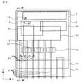
図2、図3、図4、及び図5は、スマートメーター1の概略構成の一例を示している。図2はスマートメーターの内部の概略構成の一例を示す正面図である。図3は図2に示されるA1-A1線における断面を矢印方向に見た縦断側面図である。図4は電力量計測ユニットに実装される計測基板の構成の一例を示す正面図である。図5は電力量計測ユニットの主要機能部の一例を示すブロック図である。 2, 3, 4, and 5 illustrate an example of a schematic configuration of the
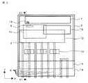
図1、図2、及び図3に示すように、スマートメーター1は、電力量を計測する計測基板3、無線通信を行う無線通信基板4a、無線通信基板4aと計測基板3を接続する汎用コネクタ5、計測基板3上に実装されるアンテナ部7、電力を供給する電力線8、電圧を電力線8から計測基板3に伝送する電圧線9、電流を検知する変成器10、変成器10で検知した電流を計測基板3に伝送する電流線11、電流の入り切りを行う開閉部12を備えた電力量計測ユニット2と、電力線8を接続する端子部13と、端子部13を覆う端子カバー14と、を備えている。 As shown in FIGS. 1, 2, and 3, the
スマートメーター1は、各需要家に設置され、通信機能を用いて使用した電力量を電力会社等の管理センターに自動的に送信できる。また、この通信機能により、管理センターから開閉部12を遠隔制御し、配線の接続及び切断を遠隔制御できる。 The
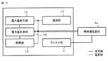
図4は、電力量計測ユニット2に実装される計測基板3の構成を示す正面図である。計測基板3は、電力量計測部15、電力量表示部16、電源部17、アンテナ部7から構成され、計測基板3の裏面にはコネクタ5を介して無線通信基板4aが取り付けられる。計測基板3と無線通信基板4aとは、コネクタ5により電気的に接続されている。無線通信基板4a及びアンテナ部7は、図示のように、それらを保護する一般的な保護カバーでは覆われていない状態で電力量計測ユニット2内、即ち電力量計本体内に配置されている。 FIG. 4 is a front view showing the configuration of the
図5は、電力量計測ユニット2の主要機能部の一例を示すブロック図である。電力量計測ユニット2は、電力量計測部15、電力量表示部16、開閉部12、電源部17、アンテナ部7から構成される計測基板3と、無線通信基板4aとを含む。
なお、図5において、電力量計測部15、電力量表示部16、開閉部12、電源部17、アンテナ部7、および無線通信基板4aの間の接続線のうち、実線で示す接続線は信号線、点線で示す接続線は電源線である。FIG. 5 is a block diagram illustrating an example of main functional units of the electric
In FIG. 5, among the connection lines among the electric
なお、図2、図3、及び図4では、構成の理解を容易にするために発明の要部以外の詳細な部分についての記載は省略している。以下で、図2、図3、図4、及び図5を参照して、提案するスマートメーター1の一例の詳細を説明する。 In FIG. 2, FIG. 3, and FIG. 4, detailed descriptions other than the essential parts of the invention are omitted for easy understanding of the configuration. Hereinafter, an example of the proposed
図1に示す端子カバー14は、非金属部材で形成される。例えば、端子カバー14は樹脂で形成される。端子カバー14は、端子部13を覆うように設置される。 The
端子部13は、電力線8を接続する。端子部13は、例えば構成部材として金属部材を含む。端子部13は、図2に示すように、電力量計測ユニット2に面して接続されている。 The
電力線8は、図2及び図3に示すように、一端は端子部13に、他端は開閉部12に接続され、Y方向に沿って配置される。電力線8は、電力会社からの電力を、開閉部12を介して各需要家の配電盤に伝搬する。 2 and 3, one end of the
電圧線9は、図3に示すように、一端は端子部13に接続され、他端は計測基板3に接続される。電圧線9は、電力線8から供給された電圧を、電力量計測部15等に伝搬する。 As shown in FIG. 3, the
変成器10は、図2及び図3に示すように、電力線8を囲うように設置される。変成器10は、電力線8に流れる電流を検知し、電力量計測部15へ伝搬される。Z方向において、変成器10は、電力量計測ユニット2の厚さの中心から奥側又は手前側のいずれかの方向に配置される。 The
電流線11は、図3に示すように、変成器10と計測基板3を接続する。電流線11は、変成器10で検知した電流を計測基板3に伝送する。 As shown in FIG. 3, the
電力量計測部15は、電力量計測ユニット2の内部に配置される。電力量計測部15は、需要家の電力量を計測する。電力量計測部15は、図5に示すように、電力量表示部16、開閉部12、及び無線通信基板4aと電気的に接続される。計測した電力量の信号を通信部及び電力量表示部16等に送る。電力量計測部15は、例えば、構成部材として金属部材を含む。 The electric
電力量表示部16は、後述する電力量計測部15で計測された電力量を可視表示する。電力量表示部16は、長辺と短辺とを有する形状である。電力量表示部16は、例えば、X方向に長い直方体形状に形成される。このとき、電力量表示部16は、電力量計測ユニット2の計測基板3に格納できる大きさに形成される。電力量表示部16は電力量計測部15で計測された電力量を可視表示するために、外側から電力量計測ユニット2の表面部分に見えるように設置されている。例えば、この電力量表示部16は、電力量計測ユニット2の表面に形成された窓部から見えるように設置される。 The power
電源部17は、電力量計測部15、電力量表示部16、開閉部12、及び無線通信基板4aに供給する電源を生成する。電力量計測部15は、例えば、構成部材として金属部材を含む。 The
開閉部12は、電力の電路を開閉するスイッチである。開閉部12は、電力量計測部15と電気的に接続される。開閉部12は、無線通信基板4aで受信された制御信号に従って電力の給停電を制御する。 The opening /
アンテナ部7は、電力量計測ユニット2において、金属部材から構成される端子部13、電力線8、電圧線9、変成器10、電流線11、及び開閉部12からY方向に距離を空けるように配置される。また、アンテナ部7は、計測基板3において、金属部材から構成される電力量計測部15、及び電源部17からY方向に距離を空けるように配置される。アンテナ部7は、計測基板3上にプリントされたパターンとして実装される。アンテナ部7には、周波数帯の異なる複数のアンテナを実装してもよい。アンテナ部7は、一端が給電点に接続され、他端が開放されている。アンテナ部7は、金属部材を含む構成部材からY方向に距離を空けて設置されており、遮蔽物がない。したがって、アンテナ部7のアンテナ性能の劣化が抑制される。 In the electric
無線通信基板4aは、無線通信を行う。無線通信基板4aは、計測基板3との接続用の汎用コネクタ5を有する。無線通信基板4aは、アンテナ部7に近接して配置されており、アンテナ部7と後述の汎用コネクタ5とを接続する接続線はパターン配線であるのでノイズが乗りにくい。したがって、アンテナ部7のアンテナ性能の劣化が抑制される。 The
計測基板3との接続用の汎用コネクタ5と、アンテナ部7の給電点とは、Y方向に近付けて配置される。図2に示す無線通信基板4aと計測基板3の接続用の汎用コネクタ5は、X方向に対して設置されても、Y方向に対して設置されてもよい。 The general-
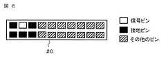
図6は、無線通信基板4a接続用のコネクタ5のピン配置の一例を示す説明図である。無線通信基板4aと計測基板3との接続用の汎用コネクタ5は、図6に参照符号20として拡大して示すように、高周波の無線信号が通過する信号ピンの周囲に接地用の接地ピンが配置されており、接地用の接地ピンが信号ピンを通過する高周波無線信号に対するシールドの作用をし、特性インピーダンスを低く調整できる。
図6において、黒塗りの四角は接地用のピン、白抜きの四角は無線信号が通過する信号ピン、ハッチングを施した四角は、電源ほか用のその他用途用のピンである。
なお、図6では汎用コネクタ20のピン数を10ピン2列としているが、その他のピン数であってもよい。FIG. 6 is an explanatory diagram showing an example of pin arrangement of the
In FIG. 6, black squares are grounding pins, white squares are signal pins through which radio signals pass, and hatched squares are pins for other uses such as a power source.
In FIG. 6, the number of pins of the general-
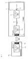
図7は、インピーダンスマッチング回路(インピーダンス整合回路とも言われる)19の配置の一例を示す説明図である。インピーダンスマッチング回路19は、計測基板に実装される汎用コネクタ5a、及び無線通信基板に実装される汎用コネクタ5bの入出力部付近、及びアンテナの給電点18付近の三箇所に配置されるが、いずれか一箇所、または二箇所であってもよい。計測基板3に実装されるインピーダンスマッチング回路19,19間は、計測基板3自体に施されたパターン配線21で接続される。インピーダンスマッチング回路19により、特性インピーダンスを調整できる。 FIG. 7 is an explanatory diagram showing an example of the arrangement of an impedance matching circuit (also referred to as an impedance matching circuit) 19. The
このような構成により、電力会社から供給された電力は、スマートメーター1の電力量測定部を介して電力線8を通り需要家の各電化製品等に供給される。電力量測定部15で検針された電力量は、電力量表示部16に信号として送られる。この電力量の情報信号は、汎用コネクタ5を介して無線通信基板4aにも送られる。無線通信基板4aは、アンテナ部7を介して管理センターに使用電力に関連する情報を載せた電波を送信する。また、無線通信基板4aは、アンテナ部7を介して管理センターなどからの制御指示等の指示を載せた電波を受信する。さらに、無線通信基板4aは、アンテナ部7を介して需要家に備わった家電等との信号の送受信により各家電への電力量の調整及び各家電の消費電力の情報等を取得する。取得された情報は、アンテナ部7で受信され、無線通信基板4aを介して電力量測定部15に送られる。また、取得された情報は、無線通信基板4aを介して管理センター若しくは需要者の端末等に送信することもできる。このようなアンテナ部7を介した通信基板と各通信場所との信号の送受信は、随時実行されている。 With such a configuration, the electric power supplied from the electric power company is supplied to each electric appliance of the consumer through the
本実施形態によれば、無線通信基板4a及び周波数帯の異なる複数のアンテナを、アンテナ特性を劣化させることなく、スマートメーター1の本体内部に実装できる。また、無線通信基板4a及び周波数帯の異なる複数のアンテナをスマートメーター1の本体内部に実装する構成としたことにより、無線通信基板4a及びアンテナ部7の専用の保護カバーを別途用いる必要がなくなり、安価な方法で実装できるという効果がある。さらに、汎用コネクタの信号ピンの周囲を接地ピンで囲うように配置し、汎用コネクタの入力部、出力部、アンテナの給電点の三箇所にマッチング回路を設置することで、特性インピーダンスの調整が可能となるため、異なる通信周波数帯の通信基板に共用することができ、従って、通信基板の付け替えのみで通信周波数帯の切り替えを実現できる。According to this embodiment, the
実施の形態2.
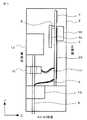
以下、図8、図9、図10、及び図11を参照して、実施の形態2について説明する。図8は実施の形態2のスマートメーターの内部の概略構成を示す正面図である。図9は図8に示されるA2-A2線における断面を矢印方向に見た縦断側面図である。図10は実施の形態2の電力量計測ユニットの主要機能部を示すブロック図である。図11は実施の形態2のリード線6を接続するコネクタ5のピン配置の説明図である。本実施形態のスマートメーター1は、実施の形態1のスマートメーター1とほぼ同等の構成である。したがって、実施の形態1と同一の構成要素には同一の参照符号を付し、詳細な説明は省略する。
Hereinafter, the second embodiment will be described with reference to FIG. 8, FIG. 9, FIG. 10, and FIG. FIG. 8 is a front view showing a schematic configuration inside the smart meter according to the second embodiment. FIG. 9 is a vertical side view of the cross section taken along the line A2-A2 shown in FIG. FIG. 10 is a block diagram illustrating main functional units of the electric energy measuring unit according to the second embodiment. FIG. 11 is an explanatory diagram of pin arrangement of the
実施の形態2では、通信方式としてPLC通信を使用し、第2のPLC通信基板4bと電力線8との接続にリード線6を用いたスマートメーター1を提案する。第2のPLC通信基板4bは、PLC通信を行う。図8及び図9に示すように、第2のPLC通信基板4bと電力線8の接続にリード線6が用いられる。第2のPLC通信基板4bは、計測基板3との接続用の汎用コネクタ5、及びリード線6を接続する汎用コネクタ22を有する。リード線6の一端は第2のPLC通信基板4bと計測基板3の接続用の汎用コネクタ5に接続し、他端は電力線8が接続される端子部13に接続される。 In the second embodiment, a
図11は、実施の形態2のコネクタのピン配置説明図である。図8に例示の第2のPLC通信基板4bと電力線8との接続に使用されるリード線6の一端は、図11に示す汎用コネクタ22のピンに接続される。なお、図11では2ピンの場合を示したが、その他のピン数であってもよい。また、図6に示した第2のPLC通信基板4bと計測基板3を接続するコネクタ5の使用していないピンを用いてもよい。 FIG. 11 is an explanatory diagram of pin arrangement of the connector according to the second embodiment. One end of the
本実施形態によれば、汎用コネクタに設けたPLC通信用の信号注入ピンと、計測基板に入力される電圧信号端子とを接続できるリード線を設けることで、無線通信とPLC通信の切り替えを通信基板の付け替えのみで実現でき、通信方式に依らず計測基板3を共通化できる。 According to the present embodiment, the communication board can be switched between wireless communication and PLC communication by providing the lead wire that can connect the signal injection pin for PLC communication provided in the general-purpose connector and the voltage signal terminal input to the measurement board. The
実施の形態3.
以下図12、図13、および図14を参照して、実施の形態3について説明する。図12は、実施の形態3のスマートメーター1の内部の概略構成を示す正面図である。図13は、図12に示されるA3-A3線における断面を矢印方向に見た縦断側面図である。図14は、実施の形態3の電力量計測ユニットの主要機能部のブロック図である。本実施形態のスマートメーター1は、実施の形態1及び実施の形態2のスマートメーター1とほぼ同等の構成である。したがって、実施の形態1及び実施の形態2と同一の構成要素には同一の参照符号を付し、詳細な説明は省略する。
Hereinafter, the third embodiment will be described with reference to FIG. 12, FIG. 13, and FIG. FIG. 12 is a front view showing a schematic configuration inside the
実施の形態3のスマートメーター1では、通信方式としてPLC通信を使用し、第3のPLC通信基板4cと電力線8との接続に、計測基板3上に施されたパターン配線23を用いたスマートメーター1を提案する。第3のPLC通信基板4cは、PLC通信を行う。図12及び図13に示すように、第3のPLC通信基板4cと電力線8との接続にパターン配線23が用いられる。パターン配線23の一端は第3のPLC通信基板4cと計測基板3の接続用の汎用コネクタ5に接続し、他端は計測基板3上の電圧が供給されるランド24に接続される。計測基板3上への電圧供給は、上述した電圧線9によってなされる。 In the
第3のPLC通信基板4cと電力線8の接続に使用されるパターン配線23の一端は、第3のPLC通信基板4cと計測基板3を接続する汎用コネクタ5の、実施の形態1で述べた無線通信用の信号ピン及び接地ピンを除いたその他のピンのいずれか、または無線通信用の信号ピンから離れたピンに接続される。One end of the
本実施形態によれば、実施の形態2に比べ、PLC通信基板と電力線8の接続をより安価な方法で実現できる。 According to the present embodiment, compared to the second embodiment, the connection between the PLC communication board and the
上述の実施形態によれば、無線通信及びPLC通信を用いるスマートメーター1において、無線通信基板、第2のPLC通信基板または第3のPLC通信基板、及びアンテナ部7をスマートメーター1の本体内部に実装し、無線通信とPLC通信の方式切替を、無線通信基板、第2のPLC通信基板または第3のPLC通信基板の付け替えのみで実現でき、小型かつ安価なスマートメーター1を提供できる。According to the above-described embodiment, in the
実施の形態4.
実施の形態1を参照して、実施の形態4について説明する。実施の形態4では、アンテナとして、実施の形態1における電力量表示部16のリードを用いたスマートメーター1を提案する。図16は、電力量表示部のリードを利用したアンテナの一例を示す平面図である。図17は、電力量表示部のリードを利用したアンテナの一例を示す平面図である。本実施形態のスマートメーター1は、実施の形態1のスマートメーター1とほぼ同等の構成である。したがって、実施の形態1と同一の構成要素には同一の参照符号を付し、詳細な説明は省略する。Embodiment 4 FIG.
The fourth embodiment will be described with reference to the first embodiment. In the fourth embodiment, a
スマートメーター1では、表示部が筐体表面付近に配置されており、長いリード27で計測基板3に接続されている。
実施の形態4のスマートメーター1では、アンテナとして、実施の形態1における電力量表示部16のリードを用いたスマートメーター1を提案する。
実施の形態4のスマートメーター1では、図16、及び図17に示すように、電力量表示部16と計測基板3とを接続する多数のリード27の少なくとも一部の複数のリードを利用して、第4のアンテナ部26を構成する。
アンテナとして用いる各リード28間は、接続端子29、及び計測基板3上に設けたパターン配線により導通させる。
第4のアンテナ部26は、アンテナとして用いる複数のリード28,28,・・・と、各リード間を接続する接続端子29と、給電点30とを含む。アンテナとして用いるリード28,28,・・・間を接続する接続端子29は、例えば電力量表示部16と計測基板3とを接続するリード27と同一の材質である。In the
The
In the
The leads 28 used as the antenna are electrically connected by the
The
無線通信基板4aは、図15に示す箇所に配置される。無線通信基板4aと計測基板3とを接続する汎用コネクタ5は、電力量表示部16に近接して配置される。
無線通信基板4aと計測基板3とを接続する汎用コネクタ5を、第4のアンテナ部26の給電点30に近接して配置することで、汎用コネクタ5と第4のアンテナ部26の給電点30間を接続するパターン配線間でノイズが乗りにくく、アンテナ性能の劣化が抑制される。The
By disposing the general-
本実施形態によれば、電力量表示部16のリードをアンテナとして用いることで、実施の形態1に比べ、アンテナの実装スペースを削減でき、小型化及び低コスト化を実現できる。 According to the present embodiment, by using the lead of the power
上述の実施形態によれば、無線通信及びPLC通信を用いるスマートメーター1において、計測基板の一部をアンテナ領域として利用することによって、複数の周波数帯のアンテナの内蔵を可能にした。また、汎用コネクタの信号ピンの周囲を接地ピンで囲うように配置し、汎用コネクタの入力部、出力部、アンテナの給電点の三箇所にマッチング回路を設置することで、特性インピーダンスの調整が可能となり、通信基板の付け替えのみで通信周波数帯の切り替えを実現できる。さらに、汎用コネクタに設けたPLC通信用の信号注入ピンと、計測基板に入力される電圧信号端子とを、リード線またはパターン配線することで、無線通信とPLC通信の切り替えを通信基板の付け替えのみで実現でき、通信方式に依らず計測基板を共通化できる。加えて、電力量表示部16のリードをアンテナとして用いることで、実施の形態1に比べ、アンテナの実装スペースを削減でき、さらなる小型化及び低コスト化を実現できる。 According to the above-described embodiment, in the
計測基板に設けられた電力量表示部を液晶パネルとし、液晶パネルと計測基板とを接続する端子の空きピンをパターンアンテナの一部とした構造にしてもよい。 The power amount display portion provided on the measurement board may be a liquid crystal panel, and the unused pins of the terminals connecting the liquid crystal panel and the measurement board may be part of the pattern antenna.
なお、前述の説明および前述の各図からも明白なように、本実施の形態1には、以下のような技術的特徴がある。
特徴点1: 電力量を計測する電力量計測部と、
電力量を表示する電力量表示部と、
外部と無線通信またはPLC通信を行う通信基板と、
電力の給電停電を行う開閉部と、
前記電力量計測部、前記電力量表示部、前記通信基板、及び前記開閉部に供給する電源を生成する電源部と、
通信基板により外部機器との無線通信を行う際に使用されるアンテナ部と、
前記電力量計測部、前記電力量表示部、通信基板、及び前記アンテナ部が搭載された計測基板と、
前記通信基板と前記計測基板とを接続するコネクタと、
前記PLC通信時に必要となる前記通信基板と電力線とを接続する配線と、
前記電力量計測部に電圧を供給する電圧線と、
前記電力線に流れる電流を検知し前記電力量計測部に出力する変成器と、
電力線を接続する端子部と、
を備えたスマートメーターであって、
メーター本体内の一端部に、それぞれ金属部を含む前記端子部、前記電圧線、前記変成器、前記電源部、及び前記開閉部が配設され、
前記メーター本体内の他端部に、前記端子部、前記電圧線、前記変成器、前記電源部、及び前記開閉部から空間的に離間して前記アンテナ部が配設されている。
特徴点2:計測基板の一部をアンテナ領域とすることによって、比較的大きなアンテナを必要とする400MHz帯においても、前記メーター本体内へのアンテナの内蔵を可能にした構成である。
特徴点3:通信基板は、メータ本体内の計測基板の裏面側の、アンテナに近接する位置に、専用の保護カバーに覆われていない裸の状態で配設されている。
特徴点4:通信基板と計測基板とは汎用のコネクタで接続され、当該コネクタにおけるピンの配置が、信号ピンの周囲を接地ピンで囲う配置である。
特徴点5:汎用のコネクタの入力部、コネクタの出力部、およびアンテナの給電点、の三箇所にインピーダンスマッチング回路が設けられている。
特徴点6:汎用のコネクタに設けたPLC通信用の信号注入ピンと、計測基板に入力される電圧信号端子(ランド)とが、パターン配線で接続されている。
特徴点7:計測基板に設けられた電力量表示部を液晶パネルとし、液晶パネルと計測基板とを接続する端子の空きピンをパターンアンテナの一部とした構造にしてある。As is clear from the above description and the respective drawings, the first embodiment has the following technical features.
Feature point 1: Electric energy measuring unit for measuring electric energy;
An electric energy display unit for displaying electric energy;
A communication board for performing wireless communication or PLC communication with the outside;
An open / close unit for power supply power outage;
A power supply unit that generates power to be supplied to the power measurement unit, the power display unit, the communication board, and the opening / closing unit;
An antenna unit used when performing wireless communication with an external device through a communication board;
A measurement board on which the power measurement unit, the power display unit, a communication board, and the antenna unit are mounted;
A connector for connecting the communication board and the measurement board;
Wiring for connecting the communication board and a power line required at the PLC communication;
A voltage line for supplying a voltage to the electric energy measuring unit;
A transformer that detects the current flowing in the power line and outputs the current to the power measurement unit;
A terminal part for connecting a power line;
A smart meter with
The terminal part including the metal part, the voltage line, the transformer, the power supply part, and the opening / closing part are disposed at one end part in the meter body,
The antenna portion is disposed spatially separated from the terminal portion, the voltage line, the transformer, the power source portion, and the opening / closing portion at the other end portion in the meter body.
Feature point 2: By configuring a part of the measurement board as an antenna region, the antenna can be built in the meter body even in a 400 MHz band that requires a relatively large antenna.
Feature 3: The communication board is arranged in a bare state not covered with a dedicated protective cover, at a position near the antenna on the back side of the measurement board in the meter body.
Feature point 4: The communication board and the measurement board are connected by a general-purpose connector, and the pin arrangement in the connector is an arrangement in which the periphery of the signal pin is surrounded by a ground pin.
Feature 5: Impedance matching circuits are provided at three locations: a general-purpose connector input section, a connector output section, and an antenna feed point.
Feature 6: A signal injection pin for PLC communication provided in a general-purpose connector and a voltage signal terminal (land) input to the measurement board are connected by pattern wiring.
Feature 7: The structure is such that the power amount display portion provided on the measurement board is a liquid crystal panel, and the unused pins of the terminals connecting the liquid crystal panel and the measurement board are part of the pattern antenna.
なお、各図中、同一符合は同一または相当部分を示す。
なお、本発明は、その発明の範囲内において、各実施の形態を適宜、変形、省略、組み合わせることができる。In addition, in each figure, the same code | symbol shows the same or an equivalent part.
In the present invention, each embodiment can be appropriately modified, omitted, or combined within the scope of the invention.
1…スマートメーター、2…電力量計測ユニット、3…計測基板、4a…無線通信基板、4b…第2のPLC通信基板、4c…第3のPLC通信基板、5…汎用コネクタ、5a…計測基板に実装される汎用コネクタ、5b…無線通信基板に実装される汎用コネクタ、6…通信基板と電力線を接続するリード線、7…アンテナ部、8…電力線、9…電圧線、10…変成器、11…電流線、12…開閉部、13…端子部、14…端子カバー、15…電力量計測部、16…電力量表示部、17…電源部、18…アンテナの給電点、19…インピーダンスマッチング回路、20…汎用コネクタ、21…計測基板上のマッチング回路間を接続するパターン配線、22…リード線を接続する汎用コネクタ、23…第3の通信基板と電力線とを接続するパターン配線、24…電圧が供給されるランド、26…第4のアンテナ部、27…電力量表示部と計測基板を接続するリード、28…アンテナとして用いるリード、29…リード間を接続する端子、30…第4のアンテナの給電点。
DESCRIPTION OF
Claims (11)
Translated fromJapanese電力量を表示する電力量表示部と、
外部と無線通信または電力線搬送通信を行う通信基板と、
電力の給電停電を行う開閉部と、
前記電力量計測部、前記電力量表示部、前記通信基板、及び前記開閉部に供給する電源を生成する電源部と、
通信基板により外部機器との無線通信を行う際に使用されるアンテナ部と、
前記電力量計測部、前記電力量表示部、通信基板、及び前記アンテナ部が搭載された計測基板と、
前記通信基板と前記計測基板とを接続するコネクタと、
電力線搬送通信時に必要となる前記通信基板と電力線とを接続する配線と、
前記電力量計測部に電圧を供給する電圧線と、
前記電力線に流れる電流を検知し前記電力量計測部に出力する変成器と、
電力線を接続する端子部と、
を備えたスマートメーターであって、
メーター本体内の一端部に、それぞれ金属部を含む前記端子部、前記電圧線、前記変成器、前記電源部、及び前記開閉部が配設され、
前記メーター本体内の他端部に、前記端子部、前記電圧線、前記変成器、前記電源部、及び前記開閉部から空間的に離間して前記アンテナ部が配設されている
ことを特徴とするスマートメーター。An electric energy measuring unit for measuring electric energy;
An electric energy display unit for displaying electric energy;
A communication board for performing wireless communication or power line carrier communication with the outside;
An open / close unit for power supply power outage;
A power supply unit that generates power to be supplied to the power measurement unit, the power display unit, the communication board, and the opening / closing unit;
An antenna unit used when performing wireless communication with an external device through a communication board;
A measurement board on which the power measurement unit, the power display unit, a communication board, and the antenna unit are mounted;
A connector for connecting the communication board and the measurement board;
A wiring for connecting the communication board and the power line needed whenpower line communication,
A voltage line for supplying a voltage to the electric energy measuring unit;
A transformer that detects the current flowing in the power line and outputs the current to the power measurement unit;
A terminal part for connecting a power line;
A smart meter with
The terminal part including the metal part, the voltage line, the transformer, the power supply part, and the opening / closing part are disposed at one end part in the meter body,
The antenna portion is disposed spatially separated from the terminal portion, the voltage line, the transformer, the power supply portion, and the opening / closing portion at the other end portion in the meter body. Smart meter to do.
前記アンテナ部と前記電力量計測部との間に前記電力量表示部が配設されている
ことを特徴とするスマートメーター。The smart meter according to claim 1,
The smart meter, wherein the power amount display unit is disposed between the antenna unit and the power amount measuring unit.
前記アンテナ部が前記計測基板の正面側に搭載されている
ことを特徴とするスマートメーター。In請 Motomeko 1 or smart meter according to claim 2,
The smart meter, wherein the antenna unit is mounted on the front side of the measurement board.
前記アンテナ部が前記計測基板の一部に前記アンテナ部が形成されている
ことを特徴とするスマートメーター。In請 Motomeko 1 or smart meter according to claim 2,
The smart meter, wherein the antenna portion is formed on a part of the measurement substrate.
前記通信基板が前記コネクタを介して前記計測基板の裏面側に搭載されている
ことを特徴とするスマートメーター。In請 Motomeko 3 or smart meter according to claim 4,
The smart meter, wherein the communication board is mounted on the back side of the measurement board via the connector.
前記開閉部、前記変成器、及び前記端子部が、前記計測基板の裏面側に、前記計測基板から空間的に離間して配設されている
ことを特徴とするスマートメーター。In the smart meter as set forth in請 Motomeko 5,
The smart meter, wherein the opening / closing part, the transformer, and the terminal part are arranged on the back side of the measurement board so as to be spatially separated from the measurement board.
前記通信基板と前記計測基板とはコネクタで接続され、当該コネクタにおけるピンの配置が、信号ピンの周囲を接地ピンで囲う配置である
ことを特徴とするスマートメーター。The smart meter according to any one of claims 1 to 6,
The smart board, wherein the communication board and the measurement board are connected by a connector, and an arrangement of pins in the connector is an arrangement in which a signal pin is surrounded by a ground pin.
前記コネクタの入力部、前記コネクタの出力部、及び前記アンテナ部の給電点、の三箇所にインピーダンスマッチング回路が設けられている
ことを特徴とするスマートメーター。In the smart meter according to any one of claims 1 to 7,
A smart meter, wherein impedance matching circuits are provided at three locations: an input portion of the connector, an output portion of the connector, and a feeding point of the antenna portion.
電力線搬送通信用の前記コネクタの信号注入ピンと、前記計測基板に入力される電圧信号端子とが、パターン配線で接続されている
ことを特徴とするスマートメーター。The smart meter according to any one of claims 1 to 8,
Smart meter to the signal injection pin of the connector of thepower line carrier communication, a voltage signal terminal to be input to the measuring substrate, characterized in that it is connected by pattern wiring.
前記電力量表示部と前記計測基板とを接続するリードで前記アンテナ部が形成されている
ことを特徴とするスマートメーター。The smart meter according to any one of claims 1 to 9,
The smart meter, wherein the antenna unit is formed by a lead connecting the power amount display unit and the measurement board.
前記電力量表示部が液晶パネルであり、前記アンテナ部が、前記液晶パネルと前記計測基板とを接続する端子の空きピンを使ったパターンアンテナである
ことを特徴とするスマートメーター。The smart meter according to any one of claims 1 to 10,
Wherein a power amount display section a liquid crystal panel, a smart meter the antenna unit, characterized in that said apattern antennausing reserved pin terminals for connecting the liquid crystal panel and the measuring board.
Applications Claiming Priority (1)
| Application Number | Priority Date | Filing Date | Title |
|---|---|---|---|
| PCT/JP2016/062528WO2017183137A1 (en) | 2016-04-20 | 2016-04-20 | Smart meter |
Publications (2)
| Publication Number | Publication Date |
|---|---|
| JPWO2017183137A1 JPWO2017183137A1 (en) | 2019-03-07 |
| JP6556340B2true JP6556340B2 (en) | 2019-08-07 |
Family
ID=60115812
Family Applications (1)
| Application Number | Title | Priority Date | Filing Date |
|---|---|---|---|
| JP2018512708AActiveJP6556340B2 (en) | 2016-04-20 | 2016-04-20 | Smart meter |
Country Status (2)
| Country | Link |
|---|---|
| JP (1) | JP6556340B2 (en) |
| WO (1) | WO2017183137A1 (en) |
Families Citing this family (4)
| Publication number | Priority date | Publication date | Assignee | Title |
|---|---|---|---|---|
| JP2021043136A (en)* | 2019-09-13 | 2021-03-18 | 東光東芝メーターシステムズ株式会社 | Electricity meter |
| JP7281390B2 (en)* | 2019-11-27 | 2023-05-25 | 東光東芝メーターシステムズ株式会社 | electricity meter |
| JP2021117059A (en)* | 2020-01-23 | 2021-08-10 | パナソニックIpマネジメント株式会社 | Measuring device |
| JP7484500B2 (en) | 2020-07-02 | 2024-05-16 | オムロン株式会社 | Power Measuring Device |
Family Cites Families (3)
| Publication number | Priority date | Publication date | Assignee | Title |
|---|---|---|---|---|
| JP2001093073A (en)* | 1999-09-17 | 2001-04-06 | Kansai Electric Power Co Inc:The | Instrument with remote meter reading function |
| JP5832406B2 (en)* | 2012-09-28 | 2015-12-16 | 三菱電機株式会社 | Power consumption measuring device |
| JP6411026B2 (en)* | 2014-01-06 | 2018-10-24 | 株式会社東芝 | Remote meter reading device |
- 2016
- 2016-04-20WOPCT/JP2016/062528patent/WO2017183137A1/ennot_activeCeased
- 2016-04-20JPJP2018512708Apatent/JP6556340B2/enactiveActive
Also Published As
| Publication number | Publication date |
|---|---|
| WO2017183137A1 (en) | 2017-10-26 |
| JPWO2017183137A1 (en) | 2019-03-07 |
Similar Documents
| Publication | Publication Date | Title |
|---|---|---|
| US10673142B2 (en) | Antenna module | |
| JP6556340B2 (en) | Smart meter | |
| US9601831B2 (en) | Radio device | |
| US9939474B2 (en) | Meter with communication function | |
| JP6411026B2 (en) | Remote meter reading device | |
| US20150185253A1 (en) | Probe module | |
| GB2541761A (en) | Communication device and smart meter | |
| CN107645054B (en) | Antenna structure and wireless communication device with same | |
| US20200044308A1 (en) | Antenna system and mobile terminal | |
| CN107735905A (en) | Antenna assembly | |
| US8810476B2 (en) | Wireless apparatus | |
| CN105849974B (en) | Antenna assembly and the wireless device for having the antenna assembly | |
| TWI573317B (en) | Wireless communication device | |
| JP6440073B2 (en) | Distribution board | |
| US11245184B2 (en) | Antenna device and electrical appliance | |
| CN205280108U (en) | Intelligence teletransmission equipment and teletransmission instrument | |
| KR101138656B1 (en) | A Coaxial Cable and A Communication Terminal thereof | |
| JP2015211248A (en) | Electronics | |
| CN107742781A (en) | Antenna structure and the mobile terminal with the antenna structure | |
| JP2019115076A (en) | Antenna module and communication device | |
| CN105444796B (en) | Intelligent telemetering equipment and remote transmission instrument | |
| JP5285731B2 (en) | Parasitic antenna and wireless communication system | |
| US10587301B2 (en) | Wireless communications module | |
| CN108292960A (en) | Electronic device with limited spurious radio emissions | |
| CN105633549A (en) | Antenna structure and wireless communication equipment using same |
Legal Events
| Date | Code | Title | Description |
|---|---|---|---|
| A521 | Request for written amendment filed | Free format text:JAPANESE INTERMEDIATE CODE: A523 Effective date:20180926 | |
| A621 | Written request for application examination | Free format text:JAPANESE INTERMEDIATE CODE: A621 Effective date:20180926 | |
| TRDD | Decision of grant or rejection written | ||
| A01 | Written decision to grant a patent or to grant a registration (utility model) | Free format text:JAPANESE INTERMEDIATE CODE: A01 Effective date:20190611 | |
| A61 | First payment of annual fees (during grant procedure) | Free format text:JAPANESE INTERMEDIATE CODE: A61 Effective date:20190709 | |
| R151 | Written notification of patent or utility model registration | Ref document number:6556340 Country of ref document:JP Free format text:JAPANESE INTERMEDIATE CODE: R151 | |
| R250 | Receipt of annual fees | Free format text:JAPANESE INTERMEDIATE CODE: R250 | |
| R250 | Receipt of annual fees | Free format text:JAPANESE INTERMEDIATE CODE: R250 | |
| R250 | Receipt of annual fees | Free format text:JAPANESE INTERMEDIATE CODE: R250 | |
| R250 | Receipt of annual fees | Free format text:JAPANESE INTERMEDIATE CODE: R250 |