JP6556149B2 - Precision casting method for hollow members - Google Patents
Precision casting method for hollow membersDownload PDFInfo
- Publication number
- JP6556149B2 JP6556149B2JP2016547221AJP2016547221AJP6556149B2JP 6556149 B2JP6556149 B2JP 6556149B2JP 2016547221 AJP2016547221 AJP 2016547221AJP 2016547221 AJP2016547221 AJP 2016547221AJP 6556149 B2JP6556149 B2JP 6556149B2
- Authority
- JP
- Japan
- Prior art keywords
- core
- model
- casting
- ceramic
- mold
- Prior art date
- Legal status (The legal status is an assumption and is not a legal conclusion. Google has not performed a legal analysis and makes no representation as to the accuracy of the status listed.)
- Expired - Fee Related
Links
- 238000000034methodMethods0.000titleclaimsdescription63
- 238000005495investment castingMethods0.000titledescription24
- 239000000919ceramicSubstances0.000claimsdescription92
- 238000005266castingMethods0.000claimsdescription66
- 238000004519manufacturing processMethods0.000claimsdescription40
- 239000000463materialSubstances0.000claimsdescription18
- 238000003801millingMethods0.000claimsdescription12
- 239000002184metalSubstances0.000claimsdescription11
- 229910052751metalInorganic materials0.000claimsdescription11
- 230000008569processEffects0.000claimsdescription9
- 238000012545processingMethods0.000claimsdescription8
- 238000003754machiningMethods0.000claimsdescription7
- 238000002844meltingMethods0.000claimsdescription6
- 230000008018meltingEffects0.000claimsdescription6
- 239000007787solidSubstances0.000claimsdescription4
- 2380000101463D printingMethods0.000claimsdescription3
- 238000000149argon plasma sinteringMethods0.000claimsdescription3
- 230000008878couplingEffects0.000claims1
- 238000010168coupling processMethods0.000claims1
- 238000005859coupling reactionMethods0.000claims1
- 239000011162core materialSubstances0.000description113
- 238000001816coolingMethods0.000description16
- 238000002347injectionMethods0.000description7
- 239000007924injectionSubstances0.000description7
- 239000007788liquidSubstances0.000description7
- PXHVJJICTQNCMI-UHFFFAOYSA-NNickelChemical compound[Ni]PXHVJJICTQNCMI-UHFFFAOYSA-N0.000description6
- 230000015572biosynthetic processEffects0.000description5
- 238000004513sizingMethods0.000description5
- 229910000601superalloyInorganic materials0.000description5
- 229910045601alloyInorganic materials0.000description4
- 239000000956alloySubstances0.000description4
- 230000008901benefitEffects0.000description4
- 238000010304firingMethods0.000description4
- 238000001746injection mouldingMethods0.000description4
- 238000005058metal castingMethods0.000description4
- 239000002002slurrySubstances0.000description4
- 238000007711solidificationMethods0.000description4
- 230000008023solidificationEffects0.000description4
- 239000011230binding agentSubstances0.000description3
- 229910017052cobaltInorganic materials0.000description3
- 239000010941cobaltSubstances0.000description3
- GUTLYIVDDKVIGB-UHFFFAOYSA-Ncobalt atomChemical compound[Co]GUTLYIVDDKVIGB-UHFFFAOYSA-N0.000description3
- 230000007547defectEffects0.000description3
- 238000005516engineering processMethods0.000description3
- 238000000227grindingMethods0.000description3
- 239000007769metal materialSubstances0.000description3
- 239000000203mixtureSubstances0.000description3
- 239000012778molding materialSubstances0.000description3
- 229910052759nickelInorganic materials0.000description3
- 238000012805post-processingMethods0.000description3
- 238000005245sinteringMethods0.000description3
- 229910000760Hardened steelInorganic materials0.000description2
- 239000000306componentSubstances0.000description2
- 239000013078crystalSubstances0.000description2
- 238000000465mouldingMethods0.000description2
- 239000000843powderSubstances0.000description2
- 239000000126substanceSubstances0.000description2
- 238000005406washingMethods0.000description2
- 229910000906BronzeInorganic materials0.000description1
- 241001522319Chloris chlorisSpecies0.000description1
- RYGMFSIKBFXOCR-UHFFFAOYSA-NCopperChemical compound[Cu]RYGMFSIKBFXOCR-UHFFFAOYSA-N0.000description1
- 241000238413OctopusSpecies0.000description1
- 230000001133accelerationEffects0.000description1
- 230000006978adaptationEffects0.000description1
- 239000000654additiveSubstances0.000description1
- 239000010974bronzeSubstances0.000description1
- 238000005524ceramic coatingMethods0.000description1
- 230000008859changeEffects0.000description1
- 230000000295complement effectEffects0.000description1
- 229910052802copperInorganic materials0.000description1
- 239000010949copperSubstances0.000description1
- KUNSUQLRTQLHQQ-UHFFFAOYSA-Ncopper tinChemical compound[Cu].[Sn]KUNSUQLRTQLHQQ-UHFFFAOYSA-N0.000description1
- 239000008358core componentSubstances0.000description1
- 230000002950deficientEffects0.000description1
- 230000001419dependent effectEffects0.000description1
- 238000007599dischargingMethods0.000description1
- 230000000694effectsEffects0.000description1
- 239000013013elastic materialSubstances0.000description1
- 210000003746featherAnatomy0.000description1
- PCHJSUWPFVWCPO-UHFFFAOYSA-NgoldChemical compound[Au]PCHJSUWPFVWCPO-UHFFFAOYSA-N0.000description1
- 229910052737goldInorganic materials0.000description1
- 239000010931goldSubstances0.000description1
- 238000009776industrial productionMethods0.000description1
- 238000009434installationMethods0.000description1
- 238000012804iterative processMethods0.000description1
- 230000007257malfunctionEffects0.000description1
- 150000002739metalsChemical class0.000description1
- 238000005555metalworkingMethods0.000description1
- 239000002245particleSubstances0.000description1
- 238000002360preparation methodMethods0.000description1
- 239000002994raw materialSubstances0.000description1
- 230000009467reductionEffects0.000description1
- 239000004576sandSubstances0.000description1
- 238000007493shaping processMethods0.000description1
- 239000000243solutionSubstances0.000description1
- 229920005992thermoplastic resinPolymers0.000description1
- 238000007514turningMethods0.000description1
- 238000011144upstream manufacturingMethods0.000description1
- 238000003466weldingMethods0.000description1
Images


Classifications
- B—PERFORMING OPERATIONS; TRANSPORTING
- B22—CASTING; POWDER METALLURGY
- B22C—FOUNDRY MOULDING
- B22C9/00—Moulds or cores; Moulding processes
- B22C9/10—Cores; Manufacture or installation of cores
- B—PERFORMING OPERATIONS; TRANSPORTING
- B22—CASTING; POWDER METALLURGY
- B22C—FOUNDRY MOULDING
- B22C7/00—Patterns; Manufacture thereof so far as not provided for in other classes
- B22C7/02—Lost patterns
- B—PERFORMING OPERATIONS; TRANSPORTING
- B22—CASTING; POWDER METALLURGY
- B22C—FOUNDRY MOULDING
- B22C9/00—Moulds or cores; Moulding processes
- B22C9/10—Cores; Manufacture or installation of cores
- B22C9/108—Installation of cores
- B—PERFORMING OPERATIONS; TRANSPORTING
- B22—CASTING; POWDER METALLURGY
- B22D—CASTING OF METALS; CASTING OF OTHER SUBSTANCES BY THE SAME PROCESSES OR DEVICES
- B22D29/00—Removing castings from moulds, not restricted to casting processes covered by a single main group; Removing cores; Handling ingots
- B22D29/001—Removing cores
- B—PERFORMING OPERATIONS; TRANSPORTING
- B33—ADDITIVE MANUFACTURING TECHNOLOGY
- B33Y—ADDITIVE MANUFACTURING, i.e. MANUFACTURING OF THREE-DIMENSIONAL [3-D] OBJECTS BY ADDITIVE DEPOSITION, ADDITIVE AGGLOMERATION OR ADDITIVE LAYERING, e.g. BY 3-D PRINTING, STEREOLITHOGRAPHY OR SELECTIVE LASER SINTERING
- B33Y10/00—Processes of additive manufacturing
- B—PERFORMING OPERATIONS; TRANSPORTING
- B33—ADDITIVE MANUFACTURING TECHNOLOGY
- B33Y—ADDITIVE MANUFACTURING, i.e. MANUFACTURING OF THREE-DIMENSIONAL [3-D] OBJECTS BY ADDITIVE DEPOSITION, ADDITIVE AGGLOMERATION OR ADDITIVE LAYERING, e.g. BY 3-D PRINTING, STEREOLITHOGRAPHY OR SELECTIVE LASER SINTERING
- B33Y80/00—Products made by additive manufacturing
- Y—GENERAL TAGGING OF NEW TECHNOLOGICAL DEVELOPMENTS; GENERAL TAGGING OF CROSS-SECTIONAL TECHNOLOGIES SPANNING OVER SEVERAL SECTIONS OF THE IPC; TECHNICAL SUBJECTS COVERED BY FORMER USPC CROSS-REFERENCE ART COLLECTIONS [XRACs] AND DIGESTS
- Y02—TECHNOLOGIES OR APPLICATIONS FOR MITIGATION OR ADAPTATION AGAINST CLIMATE CHANGE
- Y02P—CLIMATE CHANGE MITIGATION TECHNOLOGIES IN THE PRODUCTION OR PROCESSING OF GOODS
- Y02P10/00—Technologies related to metal processing
- Y02P10/25—Process efficiency
Landscapes
- Engineering & Computer Science (AREA)
- Mechanical Engineering (AREA)
- Molds, Cores, And Manufacturing Methods Thereof (AREA)
Description
Translated fromJapanese本発明は、精密鋳造の分野において、中空室構造部を有する鋳造品を、セラミックス製の型を用いて製造する方法に関する。 The present invention relates to a method of manufacturing a cast product having a hollow chamber structure using a ceramic mold in the field of precision casting.
精密鋳造は、公知のように、ロスト型内においてロストモデルを使用して行われる。ロスト型は、モデルの一度使用可能なセラミック被覆の形(Gestalt)で形成される。公知の方法は以下のステップを有している:
・硬質材料又は弾性材料からポジティブモデル(製造される鋳造品と同じ形を有する)を製造する;
・モデルへの液体の注ぎかけ及び液体凝固までの冷却により、一時的な型を製造する;
・モデルを取り出す;
・一時的な型の中空室内への第2の液体の注入及び液体凝固までの冷却により、一時的なモデルを形成する;
・一時的な型を溶融又は溶解する;
・固体のセラミックシェルを一時的なモデルの周りに形成するために、セラミックスにより一時的なモデルを被覆する;
・一時的なモデルを溶融又は溶解し、このときに発生する液体をセラミックシェルから排出する;
・溶融金属によりシェルの中空室を充填し、最終的な鋳造品を形成するために凝固させる。As is known, precision casting is performed using a lost model in a lost mold. The lost mold is formed in the model once-use ceramic coating (Gestalt). The known method has the following steps:
Manufacturing a positive model (having the same shape as the casting produced) from a hard or elastic material;
Producing a temporary mold by pouring liquid into the model and cooling to liquid solidification;
-Take out the model;
Creating a temporary model by injecting a second liquid into a temporary mold cavity and cooling to liquid solidification;
Melting or dissolving the temporary mold;
Covering the temporary model with ceramics to form a solid ceramic shell around the temporary model;
Melting or dissolving the temporary model and discharging the resulting liquid from the ceramic shell;
Fill the shell's hollow chamber with molten metal and solidify to form the final casting.
ガスタービンの多くのメーカは、改善された複数壁でかつ薄壁のガスタービン羽根を超合金から製作する。このようなガスタービン羽根は、羽根内部冷却の効果を改善するため、より多くの推力を可能にするため、及び満足できる耐用寿命を得るために、複雑化された空気冷却通路を有している。米国特許第5295530号明細書及び米国特許第5545003号明細書は、改善された複数壁でかつ薄壁のガスタービン羽根デザインに関し、この先行技術は、そのために複雑化された空気冷却通路を有している。 Many manufacturers of gas turbines make improved multi-walled and thin-walled gas turbine blades from superalloys. Such gas turbine blades have complicated air cooling passages in order to improve the effectiveness of the blade internal cooling, to allow more thrust and to obtain a satisfactory service life . U.S. Pat. No. 5,295,530 and U.S. Pat. No. 5,545,003 relate to an improved multi-walled and thin-walled gas turbine blade design, which has a complicated air cooling passage for that purpose. ing.
本発明に係る方法は、すべての形式の高価値の鋳造品の製造を可能にする。なぜならば本発明に係る方法は、鋳造品の複雑さとは無関係に、ロスト型内におけるロストモデルの形成を可能にし、同時にロストモデルの破損及び変形のおそれを排除し、変形に対して敏感なコアの使用の必要性を回避するからである。 The method according to the invention makes it possible to produce all types of high-value castings. This is because the method according to the present invention allows the formation of a lost model in the lost mold, irrespective of the complexity of the casting, and at the same time eliminates the risk of the lost model being damaged and deformed, and is sensitive to deformation. This is because it avoids the need for use of.
精密鋳造は、銅、青銅及び金のような金属から繊密な工芸品を製造するために、数千年前に使用された、最も古くから知られている変形プロセスのうちの1つである。第二次世界大戦が、特殊化された合金から成る寸法正確な部品に対する要求を高めた時に、工業生産による精密鋳造は、1940年代に一般的になった。今日、複雑な形状及び内部の冷却通路ジオメトリを有する羽根及び案内面のようなガスタービン構成部材を形成するために、精密鋳造はしばしば航空工業及びエネルギ工業において使用されている。 Precision casting is one of the oldest known deformation processes used thousands of years ago to produce delicate crafts from metals such as copper, bronze and gold . Precision casting by industrial production became common in the 1940's when World War II increased the demand for dimensionally accurate parts made of specialized alloys. Today, precision casting is often used in the aviation and energy industries to form gas turbine components such as vanes and guide surfaces with complex shapes and internal cooling passage geometry.
精密鋳造によるガスタービン動翼及びガスタービン静翼の製造は、セラミックス製の鋳造型の製造を含む。この鋳造型は、羽根形状に相当する内面を備えた外側のセラックス製のシェルと、外側のセラックス製のシェルの内部に位置している1つ又は複数のセラミックス製のコアとを有しており、コアは、支持面の内部に形成される内側の冷却通路に相当する。セラミックス製の鋳造型に溶融合金が注入され、次いで冷却され硬化する。外側のセラミックシェル及びセラミックコアは、機械的又は化学的な方法で除去され、これによって外部の成形形状、及び、(1つ又は複数のセラミックコアの形をした)内部の冷却通路の中空形状を有する鋳造された羽根ブレードを露出させることができる。 Production of gas turbine rotor blades and gas turbine stationary blades by precision casting includes the production of ceramic casting molds. The casting mold has an outer ceramic shell having an inner surface corresponding to a blade shape, and one or more ceramic cores located inside the outer ceramic shell. The core corresponds to an inner cooling passage formed inside the support surface. A molten alloy is poured into a ceramic casting mold and then cooled and hardened. The outer ceramic shell and ceramic core are removed by mechanical or chemical methods, thereby creating an outer shaped shape and a hollow shape of the internal cooling passage (in the form of one or more ceramic cores). The cast vane blades having can be exposed.
極めて複雑化されかつ細かいジオメトリ及び寸法を有する型インサート及びコアを形成するために、多数の技術が存在する。同様に、インサートを型内で位置決めし保持するためにも、一連の種々様々な技術が使用される。型装置においてコアを保持するための最も広まっている技術は、小さなセラミックピンの位置決めである。このようなセラミックピンは、型又はコアと一体に又は型及びコアの両方と一体に形成されていてよく、型の表面からコアの表面に向かって延び、コアインサートを位置決め及び支持するのに役立つ。鋳造後に、鋳造品における孔は、例えば溶接又はこれに類した方法によって、好ましくは鋳造品を形成する合金によって、満たされる。 Numerous techniques exist to form mold inserts and cores that are extremely complex and have fine geometries and dimensions. Similarly, a series of different techniques are used to position and hold the insert in the mold. The most widespread technique for holding the core in a mold apparatus is the positioning of small ceramic pins. Such ceramic pins may be formed integrally with the mold or core or integrally with both the mold and core and extend from the mold surface toward the core surface to help position and support the core insert. . After casting, the holes in the cast are filled, for example by welding or similar methods, preferably by the alloy forming the cast.
セラミックコアは、典型的には、セラミックス製のコア材料の適宜な液体を、射出成形、圧送成形又は注入することによって、所望のコア形状に形成される。セラミックス製のコア材料は、1つ又は複数のセラミックスパウダ、結合剤又は追加的な添加剤を有しており、これらは、相応に成形されたコア成形型内に注入される。 The ceramic core is typically formed into a desired core shape by injection molding, pressure molding or pouring an appropriate liquid of a ceramic core material. The ceramic core material has one or more ceramic powders, binders or additional additives, which are poured into correspondingly shaped core molds.
射出成形用のセラミックス製のコアは、次のようにして製造される。すなわち、まず、コアの対応する鋳造型半部において、耐摩耗性の焼入れ鋼から精密加工によって所望のコア型が形成され、次いで型半部は、所望のコア型に相応するインジェクション容積体にまとめられ、その後で、インジェクション容積体内へのセラミックスの成形材料の噴射が、圧力下で行われる。既に述べたように、成形材料は、セラミックスパウダと結合剤とから成る混合物を有している。セラミックス製の成形材料が「グリーン体(Gruenling)」に硬化された後で、両型半部は分離され、グリーン体が解放される。 The ceramic core for injection molding is manufactured as follows. That is, first, the desired core mold is formed by precision machining from wear-resistant hardened steel in the corresponding casting mold half of the core, and then the mold half is collected into an injection volume corresponding to the desired core mold. Thereafter, the injection of the ceramic molding material into the injection volume is carried out under pressure. As already mentioned, the molding material has a mixture of ceramic powder and binder. After the ceramic molding material is hardened to “Gruenling”, the mold halves are separated and the green body is released.
グリーン体成形コアは、型から離型された後で、1つ又は複数のステップにおいて高温で焼成され、これによって揮発性の結合剤を除去し、コアを焼結して硬化させることができる。そして例えばニッケルベース又はコバルトベースの超合金のような金属材料の鋳造時に使用するコアが得られる。このような超合金は、通常、単結晶のガスタービン羽根を鋳造するのに使用される。 After being released from the mold, the green body molded core can be fired at high temperature in one or more steps, thereby removing volatile binder and sintering the core to cure. A core for use in casting a metallic material such as a nickel-based or cobalt-based superalloy is then obtained. Such superalloys are typically used to cast single crystal gas turbine blades.
内部の冷却通路を備えた中空のガスタービン羽根の鋳造時に、焼成されたセラミックコアは、鋳造品内に内部の冷却通路を形成するために、セラミックス製の精密鋳造シェル型内に位置決めされる。中空の羽根の精密鋳造における焼成されたセラミックコアは、典型的には、薄い横断面の上流縁と下流縁とを備えた空気力学的に最適化された輪郭を有している。この前側の縁部領域と後側の縁部領域との間において、コアは、縦長の、しかしながらまた別の形に成形された複数の開口を有することができ、これによって、鋳造されたタービン羽根における冷却通路の画定及び製造を目的として、例えば内壁、段部、変向部、リブ及びこれに似た成形部を形成することができる。 During casting of a hollow gas turbine blade with an internal cooling passage, the fired ceramic core is positioned in a ceramic precision casting shell mold to form an internal cooling passage in the casting. The fired ceramic core in precision casting of hollow blades typically has an aerodynamically optimized profile with a thin cross-section upstream and downstream edges. Between the front edge region and the rear edge region, the core can have a plurality of longitudinally shaped but otherwise shaped openings, thereby casting the turbine blades. For example, an inner wall, a stepped portion, a turning portion, a rib, and a molded portion similar to this can be formed for the purpose of defining and manufacturing a cooling passage.
焼成されたセラミックコアは、次いで公知のロストワックス法における外側の成形シェルの製造時に使用される。このとき、セラミックコアは、モデル成形型内に配置され、コアの周りにロストモデルが形成され、ワックス、熱可塑性樹脂又はこれに類したもののようなモデル材料が、コアと型の内壁との間の型内の空間に、圧力下で射出される。 The fired ceramic core is then used in the production of the outer molded shell in the known lost wax process. At this time, the ceramic core is placed in a model mold, a lost model is formed around the core, and a model material such as wax, thermoplastic resin or the like is placed between the core and the inner wall of the mold. It is injected under pressure into the space in the mold.
セラミックス製の完全な鋳造型は、精密加工された焼入れ鋼から成る別の型(ワックスモデル型と呼ばれる)のまとめられた2つの半部の内部でのセラミックコアの位置決めによって形成される。この別の型は、羽根の所望の形状に相当する射出容積体を画定し、次いで溶融されたワックスが、セラミックコアの周囲でワックスモデル型内に射出される。ワックスが硬化すると、ワックスモデル型の半部は分離されて、取り除かれ、いまや羽根形状に相当するワックスモデルによって取り囲まれているセラミックコアを解放する。 A complete casting mold made of ceramics is formed by positioning the ceramic core inside two assembled halves of another mold made of precision machined hardened steel (called wax model mold). This alternative mold defines an injection volume corresponding to the desired shape of the vanes, and then the molten wax is injected into the wax model mold around the ceramic core. As the wax hardens, the wax model mold halves are separated and removed, releasing the ceramic core now surrounded by the wax model corresponding to the blade shape.
次いで、内部にセラミックコアを備えた一時的なモデルに、シェル型を構成するステップが再び繰り返される。例えばモデル/コア構成群が、繰り返しセラミックスラリ内に浸漬され、過剰のスラリは流出させられ、セラミックスタッコ(Keramikstuck)によって砂処理(besanden)され、次いで空気乾燥させられ、これによって、アッセンブリ上に成形シェルを形成する複数のセラミックス層を形成することができる。生じる取り囲まれたモデル/コアアッセンブリは、次いで、例えば蒸気オートクレーブによってモデルを除去するステップが施され、これにより、一時的なモデルつまりロストモデルを所望のように除去することができる。その結果、内部にセラミックコアを配置された成形シェルが残る。この成形シェルは次いで、金属鋳造のための成形シェルの適切な強度を得るために、高温で焼成される。 The steps of configuring the shell mold are then repeated again on a temporary model with an internal ceramic core. For example, the model / core component group is repeatedly immersed in a ceramic slurry, excess slurry is allowed to drain, besanden with ceramic ceramics, and then air dried, thereby forming on the assembly A plurality of ceramic layers forming the shell can be formed. The resulting enclosed model / core assembly is then subjected to a step of removing the model, for example by a steam autoclave, so that the temporary or lost model can be removed as desired. As a result, a molded shell having a ceramic core disposed therein remains. This molded shell is then fired at an elevated temperature to obtain the appropriate strength of the molded shell for metal casting.
ニッケルベース又はコバルトベースの超合金のような溶融金属材料が、予加熱されたシェル型内に注入されて凝固され、これによって、多結晶の又は単結晶の粒子を備えた鋳造品を形成することができる。生じる鋳造羽根ブレードは、なおセラミックコアを有しており、これによってコアの除去後に内部の冷却通路を形成することができる。コアは、洗浄又は他の汎用の技術によって除去することができる。これによって、中空に鋳造された金属製の空力学的に成形された鋳造品が生ぜしめられる。 Molten metal material, such as nickel-based or cobalt-based superalloys, is injected into a preheated shell mold and solidified, thereby forming a cast article with polycrystalline or single crystal particles Can do. The resulting cast blade blade still has a ceramic core, which can form an internal cooling passage after removal of the core. The core can be removed by washing or other general purpose techniques. This gives rise to a metal aerodynamically shaped casting cast in the hollow.
この公知の精密鋳造方法は、高価でありかつ時間がかかる。新しい羽根デザインの開発には、典型的には、数ヶ月の時間と数十万ドルの投資が必要である。さらに、デザインの決定は、セラミックコアの製造時における、例えばセラミックコアの脆性に起因する、方法に基づく制限によって、かつ細かい部分が多い又は大きなコアの場合における、時間のかかる製造によって、制限されている。金属加工工業は、このような限界を確かに認識し、例えば米国特許第7438527号明細書に記載された、羽根下流縁における冷却通路を鋳造する公知の方法のように、段階的な改善を開発している。しかしながら、また市場は、ガスタービンのますます高くなる効果及び出力を望んでいるので、現在の製造プロセスの限界は、益々問題になる。 This known precision casting method is expensive and time consuming. Developing a new feather design typically requires months of time and hundreds of thousands of dollars of investment. In addition, design decisions are limited by method-based limitations in the manufacture of ceramic cores, for example due to the brittleness of the ceramic core, and by time-consuming manufacturing in the case of many fine or large cores. Yes. The metalworking industry certainly recognizes these limitations and develops step-by-step improvements, such as the known method of casting cooling passages at the blade downstream edge described in US Pat. No. 7,438,527. doing. However, the limitations of current manufacturing processes are becoming increasingly problematic as the market also desires the increasingly higher effects and power output of gas turbines.
精密鋳造技術は、一連の不正確さを生ぜしめる。外輪郭における不正確さは、しばしば汎用の製造技術によって修正することができるのに対して、コアの、内部の構造形状における不正確さは、修正が困難であり、しばしば不正確さを排除することは不可能である。 Precision casting technology creates a series of inaccuracies. Inaccuracies in the outer contour can often be corrected by general-purpose manufacturing techniques, whereas inaccuracies in the internal structural shape of the core are difficult to correct and often eliminate inaccuracies It is impossible.
内部における不正確さは、公知の要因によって生じる。不正確さの原因としては通常、コア構造体の製造時における不正確さ、製造中のワックス型におけるコアの射出成形時における不正確さ、型の取付け時における不正確さ、セラミックス製の型の疲れによる予期しない変化又は不具合、製造中、取付け中及び鋳造工程前又は鋳造工程中における取扱い中における、シェル、コア又は固定エレメントの故障が挙げられる。 Internal inaccuracy is caused by known factors. Inaccuracy is usually due to inaccuracies in the manufacture of the core structure, inaccuracies in the injection molding of the core in the wax mold being manufactured, inaccuracies in the installation of the mold, Unexpected changes or malfunctions due to fatigue, failure of shells, cores or fixed elements during manufacturing, mounting and handling prior to or during the casting process.
コアインサートの正確な設計、寸法設定及び位置決めは、型の製造時における最も難しい問題である。本発明の方法は他の技術にも使用することができるが、精密鋳造のこの観点が、本発明の根底にある。 Accurate design, sizing and positioning of the core insert is the most difficult problem during mold manufacture. Although the method of the present invention can be used for other techniques, this aspect of precision casting is the basis of the present invention.
典型的に、鋳造型及びコアの製造において、精密なディテールを十分な解決策で確実に形成するという可能性は、制限されている。位置決めの精度、確実な寸法設定及び、細部の多い複雑な型の形成に関して、公知のシステムは極めて制限されている。 Typically, in the manufacture of casting molds and cores, the possibility of reliably producing precise details with sufficient solutions is limited. Known systems are very limited in terms of positioning accuracy, reliable sizing and formation of complex molds with many details.
コアインサートは、通常、汎用のセラミックスの射出成形を使用して、又は、適宜な焼成技術によって行われるセラミックスの成形を使用して製造される成形品である。例えば金属鋳造法で得ることができる精度に比べて、精度が著しく低い点は、セラミックコアの性質である。通常のセラミック鋳造材料組成における極めて大きな収縮、又は亀裂形成、膨出及びその他の障害を生ぜしめる極めて大きな傾向のような欠陥が存在する。従って、欠陥のあるコア及びコア位置決めに起因するコントロール不能な欠点によって生ぜしめられる高い欠陥率及びスクラップ率が存在する。又は許容誤差を上回る鋳造品を修正するためには、そしてこのような鋳造品が、後加工、研削又はこれに類した作業によってそもそも修正が可能であったとしても、後加工時に少なくともかなりの手間もしくはコストが必要である。精密鋳造の生産性及び効果は、主としてこのような制限によって限定される。 The core insert is usually a molded article manufactured using general-purpose ceramic injection molding or ceramic molding performed by an appropriate firing technique. For example, the extremely low accuracy compared to the accuracy that can be obtained by metal casting is the nature of the ceramic core. There are defects such as extremely large shrinkage or a very large tendency to cause crack formation, bulging and other obstacles in normal ceramic casting material compositions. Therefore, there are high defect rates and scrap rates caused by defective cores and uncontrollable defects due to core positioning. Or to correct castings that exceed tolerances, and even if such castings could be corrected in the first place by post-processing, grinding or similar operations, at least considerable effort during post-processing Or cost is necessary. Precision casting productivity and effectiveness are limited primarily by such limitations.
精密鋳造の、制限を加える別の観点としては、コア及び一時的なモデルのための、通常金属製の型工具の開発にかかるかなりの準備時間や、これに関連したコストが挙げられる。特にワックス型のジオメトリ及び寸法設定、グリーン体のジオメトリ及び寸法設定、焼成された型、特にコアの最終ジオメトリを含む、型工具の個々の段階の開発、及びこれらの型工具において製造された、鋳造品の配置構成及び寸法設定は、種々様々な製造ステップ中、特にセラミックスのグリーン体の焼成中における歪み、収縮及び亀裂形成を含む、多数の変化値に関連している。当該分野における当業者が良く知っているように、これらのパラメータを予め正確に予測することは不可能であり、精密鋳造型の開発は、実験と誤謬の何回も繰り返される経験に基づくプロセスである。このようなプロセスは、複雑な鋳造品に対しては、当該プロセスを運転できるようになる前に、典型的には20〜50週間にわたって実施される。 Another limiting aspect of precision casting is the considerable preparation time and associated costs associated with the development of usually metal mold tools for the core and temporary models. Wax mold geometry and sizing, green body geometry and sizing, development of individual stages of mold tools, including the final geometry of the fired mold, especially the core, and the castings produced in these mold tools Article configuration and sizing is associated with a number of change values, including strain, shrinkage and crack formation during a variety of manufacturing steps, particularly during firing of green bodies of ceramics. As those skilled in the art are well aware, it is impossible to accurately predict these parameters in advance, and the development of precision casting molds is a process based on repeated experience of experimentation and error. is there. Such a process is typically carried out for complex castings for 20-50 weeks before the process can be operated.
従って、中空体の複雑な精密鋳造は、特に個別部品の製造に制限されており、比較的多数の部品数の鋳造は、通常、方法及びそのエレメント、特に型工具のサイクル数が制限されていることに基づいて、不可能である。鋳造品のデザインにおける変更は、相応の規模の工具後加工を必要とし、従って極めて高いコスト及び長い時間がかかる。 Thus, the complex precision casting of hollow bodies is particularly restricted to the production of individual parts, and the casting of a relatively large number of parts is usually limited in the number of cycles of the method and its elements, in particular mold tools. It is impossible based on that. Changes in the casting design require a correspondingly large scale of tool post-processing and are therefore very expensive and time consuming.
従来技術は、これらの問題に注目し、このような問題の発生をある程度減じる、改善されたセラミックス組成の使用において、進歩を果たした。 The prior art has focused on these problems and has made progress in the use of improved ceramic compositions that reduce the occurrence of such problems to some extent.
これらの技術によって改善がなされたにも拘わらず、このような技術は、鋳造工程のコストを高めることになり、望まれているすべての改善は得られていない。 Despite improvements made by these techniques, such techniques increase the cost of the casting process and do not provide all the improvements that are desired.
グリーン体に対する影響、特にグリーン体の機械加工を含む技術では、セラミックス体の焼成時における寸法の変化が、いまなお一連の不正確さの原因である、ということが経験から分かっている。このような不正確さは、焼成体の望まれているジオメトリ及び寸法の実現を制限している。グリーン体の脆性のために、使用することができる技術は限られており、通常、かなりの手作業が必要になる。そしてたとえ最高の予備措置を講じ、かつ最大の注意深さをもってしても、かなりの割合のコアは、作業工程によって最終的に破壊される。 Experience has shown that in technologies involving green bodies, especially green body machining, dimensional changes during the firing of ceramic bodies are still a source of a series of inaccuracies. Such inaccuracies limit the realization of the desired geometry and dimensions of the fired body. Due to the brittleness of the green body, the techniques that can be used are limited and usually require considerable manual work. And even with the best precautions and with the greatest care, a significant percentage of the core will eventually be destroyed by the work process.
しかしながら特に不都合にも、従来技術の努力でさえも、型工具開発のサイクル時間を改善するため、又は、形状及び寸法に関して必要な精度を有する最終的な型工具を製造するのに必要となる、必要な繰り返しの数を減じるための、最新のレベルにまでほとんど達していない。従来技術は、規格外に位置するシェル及びコアの型を改訂するための、又は、型工具の開発プロセスを新たに受け入れることなく、デザイン変更のための型を変化させるための、効果的な技術を提供していない。 However, particularly disadvantageously, even prior art efforts are required to improve the mold tool development cycle time or to produce the final mold tool with the required accuracy in terms of shape and dimensions. Little has been reached to the latest level to reduce the number of iterations required. The prior art is an effective technique for revising out-of-standard shell and core molds, or for changing molds for design changes without newly accepting the mold tool development process. Not offer.
追加的な従来技術は、特に歯科の使用におけるワックスの粉砕を含んでいるが、このようなワックスの粉砕技術が、精密鋳造において直接的に使用されるわけではない。 Additional prior art includes wax grinding, particularly in dental use, but such wax grinding techniques are not directly used in precision casting.
ゆえに本発明の課題は、精密鋳造型を製造する方法、特に、改善された高い再現性、寸法安定性及び精度を有する成形コアを製造する方法を提供することである。 The object of the present invention is therefore to provide a method for producing precision casting molds, in particular a method for producing molded cores with improved high reproducibility, dimensional stability and accuracy.
この課題は、請求項1に記載の特徴を有する方法によって解決される。好適な態様は、従属請求項に記載されている。 This problem is solved by a method having the features of
本発明によって得られる利点は、今までワックスモデル及びコアを噴射するのに必要であった工具の使用が回避されること、及び、高い精度及び複雑なジオメトリを有する精密鋳造型及びコアを製造するための工具開発・サイクル時間が短縮されることである。 The advantages afforded by the present invention are that the use of tools previously required to inject wax models and cores is avoided, and precision casting molds and cores with high precision and complex geometry are produced. Tool development and cycle time for
本発明に係る方法の別の利点としては、精密鋳造型及び精密鋳造コアのジオメトリ及び寸法を迅速に変更することができ、これによって、その際に工具開発サイクルを繰り返すことなしに、構造変更のためのジオメトリ及び寸法を準備できることが挙げられる。 Another advantage of the method according to the invention is that the geometry and dimensions of the precision casting mold and the precision casting core can be changed quickly, so that structural changes can be made without repeating the tool development cycle. For example, the geometry and dimensions can be prepared.
本発明は、中空室構造部を有する鋳造品を、該鋳造品のデジタル式の幾何学座標の3Dモデルの使用下で、セラミックス製の型を用いて製造する方法である。この方法は、以下に記載のステップ、すなわち:
− (任意にまず初めに)コアの第1の(好ましくは少なくともその最後のステップにおいて鋳造技術的ではない)CNC製造法のための、中空室構造体を製造するコアの3Dモデルにおけるジオメトリの適合;
a)(好ましくはフライス加工による又は、例えば3Dプリント、選択的レーザ溶融又はレーザ焼結のような付加製造方法(generatives Fertigungsverfahren)における)第1のCNC製造法における3Dモデルに従ったコアのコンピュータ数値制御された(CNC)製造;
b)加工保持装置におけるコアの位置決め;
c)(好ましくは3Dモデルに応じて加工保持装置におけるコアの位置決めによって空間的に決定される、鋳造品体積を全面的に上回る)鋳造品よりも大きな容積体内への、コアを取り囲むようにしてのモデル材料(好ましくはモデルワックス)の注入、及びモデル材料の凝固;
d)(好ましくは最後のステップにおいて鋳造技術的ではない)第2のCNC製造法(例えば、好ましくはフライス加工による切削加工)における、3Dモデルに従った、コアを取り囲む凝固したモデル材料からの鋳造品の一時的な(ロスト)モデルの外輪郭のCNC製造;
e)ロストモデルの外輪郭へのセラミックス製の(好ましくは耐高温性のセラミックスから成る)型シェルの塗布、及び該セラミックス製の型と加工保持装置との位置決め結合部の形成;
f)加工保持装置におけるコアの周囲の、セラミックス製の型からのロストモデルの溶融除去;
g)セラミックス製の鋳造型の焼結;
h)加工保持装置におけるコアの周囲の、セラミックス製の型内への溶融金属の注入;
i)固体の鋳造品への溶融金属の凝固、及び
j)鋳造品からのセラミックス製の型及びコアの除去、
というステップを含む。The present invention is a method for producing a cast product having a hollow chamber structure using a ceramic die under the use of a 3D model of digital geometric coordinates of the cast product. This method comprises the steps described below:
-(Optionally first) geometry adaptation in the 3D model of the core producing the hollow chamber structure for the first (preferably not casting technical in at least its last step) CNC manufacturing process of the core ;
a) Computer numerical value of the core according to the 3D model in the first CNC manufacturing method (preferably by milling or in generatives Fertigungsverfahren, eg 3D printing, selective laser melting or laser sintering) Controlled (CNC) manufacturing;
b) positioning of the core in the work holding device;
c) Surrounding the core in a volume larger than the casting (preferably exceeding the entire casting volume, preferably spatially determined by the positioning of the core in the work holding device according to the 3D model) Injection of a model material (preferably a model wax) and solidification of the model material;
d) Casting from solidified model material surrounding the core, according to the 3D model, in a second CNC production method (preferably not a casting technique in the last step), for example preferably by milling CNC production of the outer profile of the temporary model of the product;
e) application of a ceramic shell (preferably made of high temperature resistant ceramic) to the outer contour of the lost model, and formation of a positioning joint between the ceramic mold and the work holding device;
f) Melting removal of the lost model from the ceramic mold around the core in the work holding device;
g) sintering of a ceramic casting mold;
h) injection of molten metal into the ceramic mold around the core in the work holding device;
i) solidification of the molten metal into a solid casting, and j) removal of the ceramic mold and core from the casting,
This step is included.
例えばガスタービン羽根を精密鋳造によって本発明のように製造することは、タービン羽根の輪郭に相当する内面を有する外側のセラミックス製のシェルと、外側のセラミックス製のシェルの内部に位置決めされていて、支持面の内部に形成される内部の冷却通路に相当する1つ又は複数のセラミックス製のコアと、を備えるセラミックス製の鋳造型の製造を含む。溶融された合金が、セラミックス製の鋳造型内に注入され、次いで冷却されて、硬化する。外側のセラミックシェル及び1つ又は複数のコアは、機械的又は化学的な方法で除去され、これによって、外側の成形形状と、(1つ又は複数のコアの形状をした)内部の冷却通路の中空形状とを備えた、鋳造された羽根ブレードを露出させることができる。 For example, manufacturing a gas turbine blade as in the present invention by precision casting is positioned inside an outer ceramic shell having an inner surface corresponding to the contour of the turbine blade, and an outer ceramic shell, Including the production of a ceramic casting mold comprising one or more ceramic cores corresponding to internal cooling passages formed within the support surface. The molten alloy is poured into a ceramic casting mold and then cooled and hardened. The outer ceramic shell and the one or more cores are removed by mechanical or chemical methods, so that the outer molded shape and the internal cooling passages (in the form of one or more cores) are removed. A cast blade blade with a hollow shape can be exposed.
しかしながら、本発明によれば、セラミックコアは、製造される鋳造品の3Dモデルに従った中空室構造体の相補型(Komlementaerform)又はネガティブ型として、コンピュータ数値制御(CNC Computer Numeric Control)により製造される。ステップa)のこの第1のCNC製造法において、フライス加工及び/又は、例えば3Dプリント、選択的レーザ溶融又はレーザ焼結のような付加製造方法を使用することができる。 However, according to the present invention, the ceramic core is manufactured by computer numerical control as a complementary type (Komlementaerform) or negative type of the hollow chamber structure according to the 3D model of the manufactured casting. The In this first CNC manufacturing method of step a), milling and / or additional manufacturing methods such as 3D printing, selective laser melting or laser sintering can be used.
3Dモデルは、任意の第1のステップにおいて、CADを用いて、当該3Dモデルが精密鋳造のため及び特にCNC製造のために適するべく特に寸法設定されるように、適合させることができる。 The 3D model can be adapted in any first step using CAD so that the 3D model is specifically sized to be suitable for precision casting and especially for CNC manufacturing.
(ステップa)及び/又はd)における)本発明に係るCNC方法において、作業を実施する工作機械を制御するための命令は、コア及び/又はモデルの3Dモデルの少なくとも1つの部分に対応して、生ぜしめられる。 In the CNC method according to the invention (in steps a) and / or d), the instructions for controlling the machine tool performing the work correspond to at least one part of the 3D model of the core and / or model. , You are born.
本発明によれば、ステップa)において、再現可能な高い精度を有する少なくとも1つの成形コアインサートが、例えばセラミックス製のコアインサートの原料の注入、セラミックスの焼成、及び例えばフライス加工のような1つ又は複数の加工技術を使用した、コアエレメントの最終加工によっても形成される。 According to the present invention, in step a), at least one molded core insert having a reproducible high accuracy is one such as, for example, injection of ceramic core insert raw material, ceramic firing, and milling, for example. Alternatively, it is formed by final processing of the core element using a plurality of processing techniques.
セラミックインサートは、均一の多孔性を有する予備焼結された又は焼結セラミックスのブロックから加工することができ、後続の処理及び取扱い中における収縮が許容される。なぜならば、予見可能だからである。すなわち、予備焼結された又は焼結セラミックスのブロックを、極めて均一なかつ極めて良好に予想可能な収縮で製造することが可能である。これは、(多孔性及び収縮特性が著しく変化する)汎用の形式で製造されたコアに比べて正確な鋳造を可能にする。 Ceramic inserts can be fabricated from pre-sintered or sintered ceramic blocks with uniform porosity, allowing shrinkage during subsequent processing and handling. Because it is predictable. That is, it is possible to produce pre-sintered or sintered ceramic blocks with very uniform and very well predictable shrinkage. This allows for accurate casting compared to cores manufactured in a general purpose format (where porosity and shrinkage properties vary significantly).
コアの表面は、加工後に被覆することができ、これによって、鋳造のための滑らかな成形表面を得ることができる。セラミックスの表面は、型内において初期成形される鋳造品の相応に滑らかな表面を模写する。 The surface of the core can be coated after processing, thereby obtaining a smooth molded surface for casting. The surface of the ceramic replicates a correspondingly smooth surface of the casting that is initially formed in the mold.
ステップb)において、1つ又は複数の加工されたコアインサートは、好ましくは該コアインサートに合わせて形成された加工保持装置内で位置決めされ、これによって、全体として最高の部材寸法安定性または部材寸法精度を、特にコア輪郭と外輪郭との間においても保証することができる。なぜならば、加工保持装置は、コアジオメトリと、ロストモデルの外輪郭の後続の高精度のCNC形状付与(例えばステップd)におけるワックスブロックのCNCフライス加工)との間における少なくとも1つの基準点を決定するための基礎としても役立つからである。 In step b), the one or more machined core inserts are preferably positioned in a work holding device formed to the core insert, so that overall best member dimensional stability or member dimension is achieved. Accuracy can be ensured especially between the core contour and the outer contour. This is because the work holding device determines at least one reference point between the core geometry and the subsequent high precision CNC shaping of the outer contour of the lost model (eg CNC milling of the wax block in step d). It is also useful as a basis for doing so.
ステップa)において、例えば5軸CNCフライス加工機において最後のコアがフライス加工された後で、ステップc)においてモデル材料が、特に温度を導かれて(Temperatur-gefuehrt)、保持装置の容積体内に注入され、凝固時に、その内部に1つ又は複数のコアインサートを備えたモデル材料ブロックを形成する。このとき容積体は、好ましくは、全面的に、3Dモデルによる鋳造品体積を超えるような大きさを有している。鋳造品体積は、3Dモデルによれば、加工保持装置内におけるコアの位置によって空間的に決定されている。 In step a), after the last core has been milled, for example in a 5-axis CNC milling machine, in step c) the model material is brought to a temperature (Temperatur-gefuehrt), in particular in the volume of the holding device. When injected and solidified, it forms a model material block with one or more core inserts therein. At this time, the volume body preferably has a size so as to exceed the entire casting volume of the 3D model. According to the 3D model, the casting product volume is spatially determined by the position of the core in the work holding device.
モデル材料ブロックを含む、上に述べた加工保持装置は、その後で例えばCNC5軸フライス加工機に位置決めされ、これによって次いで行われる、ロストワックスモデルの外輪郭のフライス加工時にも、最高の加工精度を保証することができる。モデル材料ブロックは、CNC工作機械において、部材構造に関する要求を、最高の表面品質及び寸法精度に相応して加工することができる。コアに対するステップd)におけるこの加工の位置精度は、既に機械構造において汎用の嵌合及び位置決め処置によって、加工保持装置におけるコアの緊締時及びCNC工作機械における加工保持装置の緊締時に保証することができる。しかしながら、代替的に又は追加的に、コアに(及び/又は加工保持装置に)、特にステップd)の前においてCNC工作機械によって制御される基準位置決めジオメトリが設けられていてもよく、これによって、この基準位置決めジオメトリに基づくCNC工具移動命令を方向付けること及び/又はコントロールすることができる。 The above-mentioned machine holding device, including the model material block, is then positioned, for example, on a CNC 5-axis milling machine, so that the highest machining accuracy is also achieved during the subsequent milling of the outer contour of the lost wax model. Can be guaranteed. The model material block can be processed in a CNC machine tool in accordance with the highest surface quality and dimensional accuracy for the component structure requirements. The position accuracy of this machining in step d) with respect to the core can already be ensured during the clamping of the core in the machining holding device and in the clamping of the machining holding device in the CNC machine tool by means of universal fitting and positioning procedures in the machine structure. . However, alternatively or additionally, a reference positioning geometry may be provided in the core (and / or in the work holding device), in particular prior to step d), which is controlled by the CNC machine tool, CNC tool movement commands based on this reference positioning geometry can be directed and / or controlled.
つまりセラミックス製の完全な鋳造型は、以下のように形成される:すなわち、モデル材料用の容積型の内部におけるセラミックコアの位置決め及び、その内部における例えばワックスのようなモデル材料の鋳造によって、その硬化後に、ロスト型のブランクが生じる。ワックスが硬化すると、鋳造品の外輪郭(ほぼタービンエレメントの形状)が、CNC方法で好ましくフライス加工される。そして内部にセラミックコアを備えたこのロストモデルは、シェル型を形成するためのステップに繰り返し使用される。例えばモデル/コア構成群は、セラミックスラリ内に繰り返し浸漬させられ、過剰のスラリは流出させられ、セラミックスタッコ又は砂によって湿潤され、次いで空気乾燥させられ、これによって、その上に型シェルが形成される複数のセラミック層を形成することができる。このようにして生じる取り囲まれたモデル/コア形態は、次いで、モデルを例えば蒸気オートクレーブによって除去するステップにもたらされ、これによって所望のように一時的なモデル又はロストモデルを除去することができ、その結果、セラミックコアが内部に配置された型シェルが残る。次いでこの型シェルが高温で焼成され、金属鋳造のための適宜な強度を有する型シェルを製造することができる。 In other words, a complete casting mold made of ceramics is formed as follows: by positioning the ceramic core inside the volume mold for the model material and casting the model material such as wax inside it After curing, a lost-type blank is produced. When the wax is cured, the outer contour of the casting (approximately the shape of the turbine element) is preferably milled by the CNC method. This lost model with a ceramic core inside is used repeatedly in the steps for forming the shell mold. For example, the model / core configuration group is repeatedly immersed in a ceramic slurry, excess slurry is drained, wetted with ceramic octopus or sand, and then air dried, thereby forming a mold shell thereon. A plurality of ceramic layers can be formed. The resulting enclosed model / core configuration is then brought to the step of removing the model, for example by a steam autoclave, so that the temporary or lost model can be removed as desired, As a result, a mold shell having a ceramic core disposed therein remains. The mold shell is then fired at a high temperature to produce a mold shell with suitable strength for metal casting.
ニッケルベース又はコバルトベースの超合金のような、液状の金属材料が、予加熱されたシェル型内に注入されて凝固され、これによって、同軸の又は方向付けられて凝固した多結晶のコア又は単結晶のコアを備えた鋳造品を生ぜしめることができる。このようにして鋳造された羽根は、なおセラミックコアを有しており、このコアの除去後に内部の冷却通路を形成することができる。コアは、洗浄又は汎用の技術によって、除去することができる。そして本発明によって、中空に鋳造された金属製の鋳造品が生ぜしめられる。 A liquid metallic material, such as a nickel-based or cobalt-based superalloy, is injected into a preheated shell mold and solidified, thereby producing a coaxial core or oriented solidified polycrystalline core or unit. Castings with a crystalline core can be produced. The blade thus cast still has a ceramic core, and an internal cooling passage can be formed after removal of this core. The core can be removed by washing or general purpose techniques. According to the present invention, a metal casting that is cast in the hollow is produced.
本発明の方法の最大の利点の1つは、成形品を製造するための作業時間の短縮と、型の開発プロセスの加速である。従来技術における汎用の開発の繰り返しプロセスは、本発明によれば大幅に減じられるか、又はそれどころか回避される。なぜならば、特に最終的な「正味の」型を、例えば焼結縮み及び収縮のような、セラミックスの鋳造成形技術における後での型構成工程を考慮して得る必要がないからである。最終的な型を直接製造することができるので、所望の形状及び寸法の精密鋳造品を本発明により製造することは、もはや困難でなく、また時間もかからない。特に、従来技術において必要であった試行錯誤の手順のループを回避することができる。 One of the greatest advantages of the method of the present invention is the reduction of the working time for producing the molded part and the acceleration of the mold development process. The iterative process of general purpose development in the prior art is greatly reduced or even avoided according to the present invention. This is because, in particular, the final “net” mold does not have to be taken into account later mold building steps in the ceramic casting technology, such as sintering shrinkage and shrinkage. Since the final mold can be produced directly, it is no longer difficult and time consuming to produce a precision casting of the desired shape and dimensions according to the invention. In particular, it is possible to avoid a loop of trial and error procedures required in the prior art.
本発明のこのような及びその他の利点及び特徴については、一実施形態を示す図面を参照しながら、以下で詳しく説明する。 These and other advantages and features of the present invention are described in detail below with reference to the drawings illustrating an embodiment.
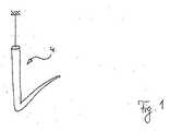
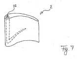
図1によれば、最初の方法ステップで、デジタル式の幾何学座標を有する、鋳造品2(図7)の3Dモデル(図示せず)を使用して、第1のCNC製造法によって、つまりCNCフライス加工(図示せず)によって、3Dモデルに従ってコア4が製造される。 According to FIG. 1, in a first method step, using a 3D model (not shown) of the casting 2 (FIG. 7) with digital geometric coordinates, the first CNC manufacturing method, The core 4 is manufactured according to the 3D model by CNC milling (not shown).
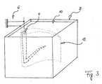
図2によれば、次の方法ステップで、加工保持装置6内でコア4が位置決めされる。コア4の周りに容積体(Volumen)8が配置され、同様に加工保持装置6内で位置決めされかつ固定される。 According to FIG. 2, the core 4 is positioned in the processing and holding device 6 in the next method step. A volume 8 is arranged around the core 4 and is similarly positioned and fixed in the processing and holding device 6.
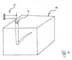
図3によれば、次の方法ステップで、コア4を取り囲むようにモデルワックス10が容積体8内に注入される。容積体8は、鋳造品体積(Gussteilkubatur)12よりも大きく、モデルワックス10は、全面的に鋳造品体積12を超えるまでコア4を取り囲むように容積体8に注入される。鋳造品体積12の三次元位置は、鋳造品2(図7)の3Dモデル(図示せず)に従って、加工保持装置6内でのコア4の位置によって決定される。 According to FIG. 3, the
図4によれば、次の方法ステップで、いまやモデル材料10がコア4の周りで凝固し、容積体8は除去される。 According to FIG. 4, in the next method step, the
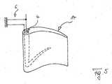
図5によれば、次の方法ステップで、鋳造品2(図7)の一時的な(ロスト)モデル14の外輪郭がコア4の周りに製造される。つまり、凝固したモデル材料10から、3Dモデル(図示せず)に従った第2のCNC製造法によって、つまり同様にCNCフライス加工(図示せず)によって製造される。 According to FIG. 5, the outer contour of the temporary (lost)
図6によれば、次の方法ステップで、ロストモデル14の外輪郭にセラミックス製の型16が塗布される。このとき、セラミックス製の型16と加工保持装置6との位置決め結合部18が形成され、この結果、セラミックス製の型16は、コア4に対して、鋳造品2(図7)の3Dモデル(図示せず)に従って寸法正確に、加工保持装置6によって位置決めされる。次の方法ステップで、コア4を取り囲むセラミックス製の型16からロストモデル14が除去される(コア4及びセラミックス製の型16は引き続き加工保持装置6によって保持されかつ互いに位置決めされる)。これによって、セラミックス製のコア4の表面とセラミックス製の型16の内面との間に、中空型20が形成される。次の方法ステップで、この中空型20内に、溶融金属(図示せず)が注入される。次の方法ステップで、この溶融金属が冷却される。 According to FIG. 6, a
溶融金属(図示せず)は凝固して固体の鋳造品2を形成し、この鋳造品2は、図7に示すように、次の方法ステップで、該鋳造品2からのセラミックス製の型16及びコア4の除去によって見えるようになり、大きな寸法精度を有する、コア4に相当する中空室構造部22を有する部材として使用することができる。 Molten metal (not shown) is solidified to form a
Claims (4)
Translated fromJapanesea)第1のCNC製造法により、3Dモデルに従ってコア(4)をCNC製造し;
b)3Dモデルに従って決定される鋳造品体積(12)よりも形状が大きいことを除いて、前記鋳造品(2)の形状とは無関係の任意の形状を有している容積体(8)を準備し;
c)前記容積体(8)が前記コア(4)の周りに配置され、3Dモデルに従って加工保持装置(6)によって前記容積体(8)内に前記コア(4)を位置決めし、前記容積体(8)内にモデル材料(10)を注入し、前記モデル材料(10)を凝固させてモデル材料ブロックを形成し;
d)第2のCNC製造法により、3Dモデルに従って、前記コア(4)を取り囲む凝固したモデル材料ブロックから前記鋳造品のロストモデル(14)の外輪郭をCNC製造し;
e)ロストモデル(14)の外輪郭にセラミックス製の型(16)を塗布し、該セラミックス製の型(16)と前記加工保持装置(6)との位置決め結合部(18)を形成して3Dモデルに従って前記加工保持装置(6)によって前記コア(4)に対して前記セラミックス製の型(16)を位置決めし;
f)前記加工保持装置(6)内の前記コア(4)の周囲の、前記セラミックス製の型(16)から前記ロストモデル(14)を除去し;
g)前記加工保持装置(6)内の前記コア(4)の周囲の、セラミックス製の型(16)内に金属を注入し;
h)固体の鋳造品へと溶融金属を凝固させ;
i)前記鋳造品から前記セラミックス製の型(16)及び前記コア(4)を除去する
ステップを含むことを特徴とする、鋳造品を製造する方法。A method for producing a cast product (2) having a hollow chamber structure (22) using a ceramic mold (16) using a 3D model of digital geometric coordinates of the cast product. The steps described below, ie:
a) CNC manufacturing the core (4) according to the 3D model according to the first CNC manufacturing method;
b) A volume (8) having an arbitrary shape unrelated to the shape of the casting (2), except that the shape is larger than the casting volume (12) determined according to the 3D model. Prepare;
c) Thevolume body (8) is arranged around the core (4), and the core (4) is positioned in the volume body (8) by the work holding device (6) according to the 3D model, and the volume body (8) injecting amodel material (10)ina model material block is formed by solidifying the model material (10);
d) CNC manufacturing the outer contour of the lost model (14) of the casting from a solidified model materialblock surrounding the core (4) according to a 3D model according to a second CNC manufacturing method;
ceramic mold (16) is applied to the outer contour of e) lost model (14),to form a positioning coupling portion between the machining holding device and said ceramic mold (16) (6) (18)Positioning the ceramic mold (16) with respect to the core (4) by the work holding device (6) according to a 3D model ;
f) removing the lost model (14) from the ceramic mold (16) around the core (4) in the processing and holding device (6);
g) pouring metal into a ceramic mold (16) around the core (4) in the processing and holding device (6);
h) solidifying the molten metal into a solid casting;
i) A method for producing a cast product, comprising the step of removing the ceramic mold (16) and the core (4) from the cast product.
Applications Claiming Priority (3)
| Application Number | Priority Date | Filing Date | Title |
|---|---|---|---|
| DE201310016868DE102013016868A1 (en) | 2013-10-11 | 2013-10-11 | Investment casting of hollow components |
| DE102013016868.6 | 2013-10-11 | ||
| PCT/EP2014/002739WO2015051916A1 (en) | 2013-10-11 | 2014-10-09 | Investment casting of hollow components |
Publications (2)
| Publication Number | Publication Date |
|---|---|
| JP2016532567A JP2016532567A (en) | 2016-10-20 |
| JP6556149B2true JP6556149B2 (en) | 2019-08-07 |
Family
ID=52011127
Family Applications (1)
| Application Number | Title | Priority Date | Filing Date |
|---|---|---|---|
| JP2016547221AExpired - Fee RelatedJP6556149B2 (en) | 2013-10-11 | 2014-10-09 | Precision casting method for hollow members |
Country Status (9)
| Country | Link |
|---|---|
| US (1) | US10357819B2 (en) |
| EP (1) | EP3055089B1 (en) |
| JP (1) | JP6556149B2 (en) |
| CN (1) | CN105792962A (en) |
| CA (1) | CA2926778A1 (en) |
| DE (1) | DE102013016868A1 (en) |
| MX (1) | MX383776B (en) |
| RU (1) | RU2676539C2 (en) |
| WO (1) | WO2015051916A1 (en) |
Families Citing this family (17)
| Publication number | Priority date | Publication date | Assignee | Title |
|---|---|---|---|---|
| US10697305B2 (en)* | 2016-01-08 | 2020-06-30 | General Electric Company | Method for making hybrid ceramic/metal, ceramic/ceramic body by using 3D printing process |
| LU92951B1 (en)* | 2016-01-20 | 2017-08-07 | Intelprop S A | Swivel lifting point for lifting loads |
| GB201608336D0 (en) | 2016-05-12 | 2016-06-29 | Rolls Royce Plc | A method of providing a fixture for a ceramic article, a method of machining a ceramic article and a method of investment casting using a ceramic article |
| US10279388B2 (en) | 2016-08-03 | 2019-05-07 | General Electric Company | Methods for forming components using a jacketed mold pattern |
| FR3059259B1 (en) | 2016-11-29 | 2019-05-10 | Jy'nove | PROCESS FOR PRODUCING A CERAMIC FOUNDRY CORE |
| US10391670B2 (en)* | 2017-06-28 | 2019-08-27 | General Electric Company | Additively manufactured integrated casting core structure with ceramic shell |
| DE102017122973A1 (en) | 2017-10-04 | 2019-04-04 | Flc Flowcastings Gmbh | Method for producing a ceramic core for producing a cavity-type casting and ceramic core |
| FR3074800B1 (en)* | 2017-12-11 | 2019-11-01 | S.A.S 3Dceram-Sinto | PROCESS FOR MANUFACTURING PIECES OF CERAMIC MATERIAL BY THE TECHNIQUE OF ADDITIVE PROCESSES |
| DE102018200705A1 (en) | 2018-01-17 | 2019-07-18 | Flc Flowcastings Gmbh | Method for producing a ceramic core for producing a cavity-type casting and ceramic core |
| WO2019213597A1 (en)* | 2018-05-04 | 2019-11-07 | Addleap Ab | A support edifice for three-dimensional printing |
| WO2019245532A1 (en)* | 2018-06-19 | 2019-12-26 | Siemens Aktiengesellschaft | Manufacturing method for finishing of ceramic cores flash |
| ES2891542T3 (en)* | 2018-09-03 | 2022-01-28 | Johannes Michael Otto Gbr Vertreten Durch Die Ges Johannes Otto Und Michael Otto | Method for the production of a model mold core blank, a model mold core and a precision casting mold, as well as a casting method for the production of a casting with a cavity structure |
| EP4069447B1 (en)* | 2020-01-13 | 2024-03-06 | Siemens Energy Global GmbH & Co. KG | Rapid manufacturing process for high definition ceramic core used for investment casting applications |
| US12285798B2 (en) | 2020-06-01 | 2025-04-29 | LightSpeed Concepts Inc. | Tool-less method for making molds, cores, and temporary tools |
| EP4146449A4 (en)* | 2020-06-09 | 2024-06-26 | Essentium, Inc. | TOOL FORMED FROM A 3D PRINTED TOOL FRAME |
| KR102325280B1 (en)* | 2020-08-26 | 2021-11-11 | 두산중공업 주식회사 | Core-wax assembly for precision casting manufacturing method |
| US11813665B2 (en)* | 2020-09-14 | 2023-11-14 | General Electric Company | Methods for casting a component having a readily removable casting core |
Family Cites Families (17)
| Publication number | Priority date | Publication date | Assignee | Title |
|---|---|---|---|---|
| US5295530A (en)* | 1992-02-18 | 1994-03-22 | General Motors Corporation | Single-cast, high-temperature, thin wall structures and methods of making the same |
| US5339888A (en)* | 1993-07-15 | 1994-08-23 | General Electric Company | Method for obtaining near net shape castings by post injection forming of wax patterns |
| US5465780A (en) | 1993-11-23 | 1995-11-14 | Alliedsignal Inc. | Laser machining of ceramic cores |
| CA2134805A1 (en)* | 1993-11-29 | 1995-05-30 | Furgan Z. Shaikh | Rapidly making complex castings |
| DE4340646A1 (en) | 1993-11-30 | 1995-06-01 | Mec Gmbh | Method and device for producing a workpiece serving as a prototype |
| RU2093298C1 (en)* | 1995-04-10 | 1997-10-20 | Ульяновский государственный технический университет | Method for manufacturing press moulds for production of investment patterns of noncircular gear wheels |
| US6513567B2 (en)* | 1998-11-04 | 2003-02-04 | Ford Global Technologies, Inc. | Method of making a spray formed rapid tool |
| JP2004330280A (en)* | 2003-05-12 | 2004-11-25 | Ishikawajima Harima Heavy Ind Co Ltd | Heat-resistant ceramic core having three-dimensional shape and method of manufacturing cast product thereof |
| US7302990B2 (en)* | 2004-05-06 | 2007-12-04 | General Electric Company | Method of forming concavities in the surface of a metal component, and related processes and articles |
| CA2511154C (en)* | 2004-07-06 | 2012-09-18 | General Electric Company | Synthetic model casting |
| FR2878458B1 (en) | 2004-11-26 | 2008-07-11 | Snecma Moteurs Sa | METHOD FOR MANUFACTURING CERAMIC FOUNDRY CORES FOR TURBOMACHINE BLADES, TOOL FOR IMPLEMENTING THE METHOD |
| US7438527B2 (en) | 2005-04-22 | 2008-10-21 | United Technologies Corporation | Airfoil trailing edge cooling |
| JP4641464B2 (en) | 2005-08-19 | 2011-03-02 | アイコクアルファ株式会社 | Titanium compressor wheel manufacturing method |
| EP1772210A3 (en) | 2005-09-30 | 2008-05-28 | General Electric Company | Methods for making ceramic casting cores and cores |
| DE102007012321A1 (en) | 2007-03-09 | 2008-09-11 | Rolls-Royce Deutschland Ltd & Co Kg | Process for investment casting of metallic components with thin through-channels |
| DE102008037534A1 (en)* | 2008-11-07 | 2010-05-12 | General Electric Co. | Production of a gas turbine component, e.g. blade, comprises forming a one-part disposable core and shell mold of a gas turbine component, introducing a rod through the mold and further processing |
| US20110042858A1 (en)* | 2009-08-19 | 2011-02-24 | Vinch Jr Samuel D | Method of making molds with production ready surfaces |
- 2013
- 2013-10-11DEDE201310016868patent/DE102013016868A1/ennot_activeWithdrawn
- 2014
- 2014-10-09CACA2926778Apatent/CA2926778A1/ennot_activeAbandoned
- 2014-10-09EPEP14808483.3Apatent/EP3055089B1/enactiveActive
- 2014-10-09MXMX2016004656Apatent/MX383776B/enunknown
- 2014-10-09CNCN201480056067.5Apatent/CN105792962A/enactivePending
- 2014-10-09USUS15/028,384patent/US10357819B2/ennot_activeExpired - Fee Related
- 2014-10-09WOPCT/EP2014/002739patent/WO2015051916A1/enactiveApplication Filing
- 2014-10-09JPJP2016547221Apatent/JP6556149B2/ennot_activeExpired - Fee Related
- 2014-10-09RURU2016121593Apatent/RU2676539C2/enactive
Also Published As
| Publication number | Publication date |
|---|---|
| EP3055089A1 (en) | 2016-08-17 |
| MX383776B (en) | 2025-03-14 |
| RU2016121593A (en) | 2017-12-06 |
| RU2676539C2 (en) | 2019-01-09 |
| US20160256918A1 (en) | 2016-09-08 |
| RU2016121593A3 (en) | 2018-06-27 |
| CA2926778A1 (en) | 2015-04-16 |
| US10357819B2 (en) | 2019-07-23 |
| DE102013016868A1 (en) | 2015-04-16 |
| MX2016004656A (en) | 2016-11-14 |
| CN105792962A (en) | 2016-07-20 |
| EP3055089B1 (en) | 2019-11-27 |
| JP2016532567A (en) | 2016-10-20 |
| WO2015051916A1 (en) | 2015-04-16 |
Similar Documents
| Publication | Publication Date | Title |
|---|---|---|
| JP6556149B2 (en) | Precision casting method for hollow members | |
| EP3096900B1 (en) | Method of additive manufacturing of a mold | |
| EP2777842B1 (en) | Cast-in cooling features especially for turbine airfoils | |
| US12318837B2 (en) | Investment casting process for hollow components | |
| US20200338630A1 (en) | Method for producing a ceramic core for the production of a casting having hollow structures and ceramic core | |
| CN111182982A (en) | Method for producing a ceramic core for producing a cast part having a cavity structure, and ceramic core | |
| Thomas et al. | A review on transition in the manufacturing of mechanical components from conventional techniques to rapid casting using rapid prototyping | |
| Balyakin et al. | Rapid prototyping technology for manufacturing GTE turbine blades | |
| KR101358278B1 (en) | Lost wax casting method of the nozzle ring | |
| EP4069447B1 (en) | Rapid manufacturing process for high definition ceramic core used for investment casting applications | |
| Pradyumna et al. | Wax patterns for integrally cast rotors/stators of aeroengine gas turbines | |
| Nguyen et al. | A study on the Ability to Fabricate Mold Using 3D Printing Technology and Evaluate the Surface Roughness of Products in Investment Casting | |
| JP7100399B2 (en) | Model Mold Core A method for making blanks, model mold cores, and precision molds, and a casting method for making cast parts with void structures. | |
| Magerramova et al. | Development of a method for manufacturing ceramic tooling for precision casting of blades made of heat-resistant alloys using additive technologies | |
| Pradyumna et al. | TECHNOLOGY OF CERAMIC CORES–PROCESS, TOOLING, INSPECTION AND APPLICATIONS | |
| Futas et al. | DIMENSIONING GATING SYSTEM FOR THE CASTING PRODUCED BY INVESTMENT CASTING AND ITS VERIFICATION VIA COMPUTER SIMULATION | |
| Atwood et al. | Rapid prototyping: A paradigm shift in investment casting | |
| Behera | A conceptual design of pattern to replace investment casting | |
| HK1196331B (en) | Cast-in cooling features especially for turbine airfoils |
Legal Events
| Date | Code | Title | Description |
|---|---|---|---|
| A621 | Written request for application examination | Free format text:JAPANESE INTERMEDIATE CODE: A621 Effective date:20170911 | |
| A977 | Report on retrieval | Free format text:JAPANESE INTERMEDIATE CODE: A971007 Effective date:20180823 | |
| A131 | Notification of reasons for refusal | Free format text:JAPANESE INTERMEDIATE CODE: A131 Effective date:20180910 | |
| A601 | Written request for extension of time | Free format text:JAPANESE INTERMEDIATE CODE: A601 Effective date:20181210 | |
| A521 | Request for written amendment filed | Free format text:JAPANESE INTERMEDIATE CODE: A523 Effective date:20190208 | |
| TRDD | Decision of grant or rejection written | ||
| A01 | Written decision to grant a patent or to grant a registration (utility model) | Free format text:JAPANESE INTERMEDIATE CODE: A01 Effective date:20190610 | |
| A61 | First payment of annual fees (during grant procedure) | Free format text:JAPANESE INTERMEDIATE CODE: A61 Effective date:20190709 | |
| R150 | Certificate of patent or registration of utility model | Ref document number:6556149 Country of ref document:JP Free format text:JAPANESE INTERMEDIATE CODE: R150 | |
| LAPS | Cancellation because of no payment of annual fees |