JP6555827B2 - Communication device and communication method - Google Patents
Communication device and communication methodDownload PDFInfo
- Publication number
- JP6555827B2 JP6555827B2JP2016548812AJP2016548812AJP6555827B2JP 6555827 B2JP6555827 B2JP 6555827B2JP 2016548812 AJP2016548812 AJP 2016548812AJP 2016548812 AJP2016548812 AJP 2016548812AJP 6555827 B2JP6555827 B2JP 6555827B2
- Authority
- JP
- Japan
- Prior art keywords
- frame structure
- subframe
- ofdm symbol
- ofdm
- symbol
- Prior art date
- Legal status (The legal status is an assumption and is not a legal conclusion. Google has not performed a legal analysis and makes no representation as to the accuracy of the status listed.)
- Active
Links
Images


Classifications
- H—ELECTRICITY
- H04—ELECTRIC COMMUNICATION TECHNIQUE
- H04L—TRANSMISSION OF DIGITAL INFORMATION, e.g. TELEGRAPHIC COMMUNICATION
- H04L5/00—Arrangements affording multiple use of the transmission path
- H04L5/0001—Arrangements for dividing the transmission path
- H04L5/0003—Two-dimensional division
- H04L5/0005—Time-frequency
- H04L5/0007—Time-frequency the frequencies being orthogonal, e.g. OFDM(A) or DMT
- H—ELECTRICITY
- H04—ELECTRIC COMMUNICATION TECHNIQUE
- H04J—MULTIPLEX COMMUNICATION
- H04J11/00—Orthogonal multiplex systems, e.g. using WALSH codes
- H—ELECTRICITY
- H04—ELECTRIC COMMUNICATION TECHNIQUE
- H04L—TRANSMISSION OF DIGITAL INFORMATION, e.g. TELEGRAPHIC COMMUNICATION
- H04L41/00—Arrangements for maintenance, administration or management of data switching networks, e.g. of packet switching networks
- H04L41/08—Configuration management of networks or network elements
- H04L41/0803—Configuration setting
- H04L41/0823—Configuration setting characterised by the purposes of a change of settings, e.g. optimising configuration for enhancing reliability
- H04L41/083—Configuration setting characterised by the purposes of a change of settings, e.g. optimising configuration for enhancing reliability for increasing network speed
- H—ELECTRICITY
- H04—ELECTRIC COMMUNICATION TECHNIQUE
- H04L—TRANSMISSION OF DIGITAL INFORMATION, e.g. TELEGRAPHIC COMMUNICATION
- H04L47/00—Traffic control in data switching networks
- H04L47/70—Admission control; Resource allocation
- H04L47/78—Architectures of resource allocation
- H04L47/783—Distributed allocation of resources, e.g. bandwidth brokers
- H—ELECTRICITY
- H04—ELECTRIC COMMUNICATION TECHNIQUE
- H04L—TRANSMISSION OF DIGITAL INFORMATION, e.g. TELEGRAPHIC COMMUNICATION
- H04L47/00—Traffic control in data switching networks
- H04L47/70—Admission control; Resource allocation
- H04L47/80—Actions related to the user profile or the type of traffic
- H04L47/806—Broadcast or multicast traffic
- H—ELECTRICITY
- H04—ELECTRIC COMMUNICATION TECHNIQUE
- H04L—TRANSMISSION OF DIGITAL INFORMATION, e.g. TELEGRAPHIC COMMUNICATION
- H04L5/00—Arrangements affording multiple use of the transmission path
- H—ELECTRICITY
- H04—ELECTRIC COMMUNICATION TECHNIQUE
- H04L—TRANSMISSION OF DIGITAL INFORMATION, e.g. TELEGRAPHIC COMMUNICATION
- H04L5/00—Arrangements affording multiple use of the transmission path
- H04L5/0001—Arrangements for dividing the transmission path
- H04L5/0003—Two-dimensional division
- H04L5/0005—Time-frequency
- H04L5/0007—Time-frequency the frequencies being orthogonal, e.g. OFDM(A) or DMT
- H04L5/001—Time-frequency the frequencies being orthogonal, e.g. OFDM(A) or DMT the frequencies being arranged in component carriers
- H—ELECTRICITY
- H04—ELECTRIC COMMUNICATION TECHNIQUE
- H04L—TRANSMISSION OF DIGITAL INFORMATION, e.g. TELEGRAPHIC COMMUNICATION
- H04L41/00—Arrangements for maintenance, administration or management of data switching networks, e.g. of packet switching networks
- H04L41/08—Configuration management of networks or network elements
- H04L41/0803—Configuration setting
- H04L41/0823—Configuration setting characterised by the purposes of a change of settings, e.g. optimising configuration for enhancing reliability
- H—ELECTRICITY
- H04—ELECTRIC COMMUNICATION TECHNIQUE
- H04L—TRANSMISSION OF DIGITAL INFORMATION, e.g. TELEGRAPHIC COMMUNICATION
- H04L5/00—Arrangements affording multiple use of the transmission path
- H04L5/003—Arrangements for allocating sub-channels of the transmission path
- H04L5/0048—Allocation of pilot signals, i.e. of signals known to the receiver
- H—ELECTRICITY
- H04—ELECTRIC COMMUNICATION TECHNIQUE
- H04L—TRANSMISSION OF DIGITAL INFORMATION, e.g. TELEGRAPHIC COMMUNICATION
- H04L5/00—Arrangements affording multiple use of the transmission path
- H04L5/003—Arrangements for allocating sub-channels of the transmission path
- H04L5/0053—Allocation of signalling, i.e. of overhead other than pilot signals
- H04L5/0055—Physical resource allocation for ACK/NACK
Landscapes
- Engineering & Computer Science (AREA)
- Signal Processing (AREA)
- Computer Networks & Wireless Communication (AREA)
- Mobile Radio Communication Systems (AREA)
Description
Translated fromJapanese 本発明は、通信装置、および通信方法に関する。
The present invention relates to acommunication device and a communication method.
近年、スマートフォンやタブレット端末の普及に伴い、モバイル伝送におけるトラフィックは、指数的に増大を続けており、今後もさらに増大することが予想されている。このような無線トラフィックの増大の対策の1つとして、帯域幅を増加させる検討が行なわれている。3GPP(3rd Generation Partnership Project)によるLTE(Long Term Evolution)、LTE−A(LTE-Advanced)では、複数のコンポーネントキャリアを束ねて広帯域を実現するキャリアアグリゲーションが検討されている。このキャリアアグリゲーションについては非特許文献1に記載されている。非特許文献1の方法では、一つのコンポーネントキャリアのシステム帯域幅は最大20MHzに設定され、一つの端末装置に割り当てられる最大のコンポーネントキャリア数は5に設定されている。 In recent years, with the spread of smartphones and tablet terminals, traffic in mobile transmission continues to increase exponentially and is expected to increase further in the future. As one of countermeasures against such an increase in radio traffic, studies have been made to increase the bandwidth. In LTE (Long Term Evolution) and LTE-A (LTE-Advanced) based on 3GPP (3rd Generation Partnership Project), carrier aggregation that bundles a plurality of component carriers to realize a wide band is being studied. This carrier aggregation is described in
しかしながら、非特許文献1に記載の方法では最大100MHzまでしか帯域幅を広げることができず、無線トラフィックの増加に限界があるという問題がある。 However, the method described in Non-Patent
本発明はこのような事情を鑑みてなされたものであり、その目的は、より広帯域を用いた通信が可能な通信装置、および通信方法を提供することにある。
The present invention has been made in view of such circumstances, and an object of the present invention is to provide acommunication device and a communication method capable ofcommunication using a wider band.
上述した課題を解決するために本発明に係る通信装置、および通信方法の構成は、次の通りである。In order to solve the above-described problems, the configuration of thecommunication device and the communication method according to the present invention is as follows.
本発明の端末装置は、少なくともサブキャリア間隔と最大システム帯域幅がそれぞれ、15kHzと20MHzである第1のフレーム構造の信号を受信する端末装置であって、少なくとも前記サブキャリア間隔と前記最大システム帯域幅のいずれかが前記第1のフレーム構造と異なる第2のフレーム構造をさらに受信する。 A terminal apparatus according to the present invention is a terminal apparatus that receives a signal having a first frame structure in which at least a subcarrier interval and a maximum system bandwidth are 15 kHz and 20 MHz, respectively, and at least the subcarrier interval and the maximum system band A second frame structure is received that is different in any of the widths from the first frame structure.
また、本発明の端末装置において、前記第2のフレーム構造のサブキャリア間隔は15kHzより大きい。 In the terminal device according to the present invention, the subcarrier interval of the second frame structure is greater than 15 kHz.
また、本発明の端末装置において、前記第2のフレーム構造のサブキャリア間隔は15kHzのm倍(mは自然数)である。 In the terminal device of the present invention, the subcarrier interval of the second frame structure is m times 15 kHz (m is a natural number).
また、本発明の端末装置において、前記第1のフレーム構造のサブフレームは14OFDMシンボルであり、前記第2のフレーム構造のサブフレームは14のm倍個のOFDMシンボルであり、前記第2のフレーム構造のサブフレームグループは14OFDMシンボルである。 Also, in the terminal apparatus of the present invention, the subframe of the first frame structure is 14 OFDM symbols, the subframe of the second frame structure is m times OFDM symbols of 14, and the second frame The structure subframe group is 14 OFDM symbols.
また、本発明の端末装置において、前記第2のフレーム構造の最大システム帯域幅は20MHzより大きい。 In the terminal device of the present invention, the maximum system bandwidth of the second frame structure is greater than 20 MHz.
また、本発明の端末装置において、前記第1のフレーム構造のリソースブロックは12サブキャリアであり、前記第2のフレーム構造のリソースブロックは12のn倍(nは自然数)個のサブキャリアであり、前記第2のフレーム構造のサブリソースブロックは12サブキャリアである。 In the terminal device of the present invention, the resource block of the first frame structure is 12 subcarriers, and the resource block of the second frame structure is n times (n is a natural number) subcarriers of 12. , The sub-resource block of the second frame structure is 12 subcarriers.
本発明の基地局装置は、少なくともサブキャリア間隔と最大システム帯域幅がそれぞれ、15kHzと20MHzである第1のフレーム構造の信号を送信する基地局装置であって、少なくとも前記サブキャリア間隔と前記最大システム帯域幅のいずれかが前記第1のフレーム構造と異なる第2のフレーム構造をさらに送信する。 The base station apparatus of the present invention is a base station apparatus that transmits a signal having a first frame structure in which at least a subcarrier interval and a maximum system bandwidth are 15 kHz and 20 MHz, respectively, and at least the subcarrier interval and the maximum A second frame structure is transmitted, wherein any of the system bandwidths is different from the first frame structure.
また、本発明の基地局装置において、前記第2のフレーム構造のサブキャリア間隔は15kHzより大きい。 In the base station apparatus of the present invention, the subcarrier interval of the second frame structure is greater than 15 kHz.
また、本発明の基地局装置において、前記第2のフレーム構造のサブキャリア間隔は15kHzのm倍(mは自然数)である。 In the base station apparatus of the present invention, the subcarrier interval of the second frame structure is m times 15 kHz (m is a natural number).
また、本発明の基地局装置において、前記第1のフレーム構造のサブフレームは14OFDMシンボルであり、前記第2のフレーム構造のサブフレームは14のm倍個のOFDMシンボルであり、前記第2のフレーム構造のサブフレームグループは14OFDMシンボルである。 In the base station apparatus of the present invention, the subframe of the first frame structure is 14 OFDM symbols, the subframe of the second frame structure is m times OFDM symbols of 14, and the second frame structure The subframe group of the frame structure is 14 OFDM symbols.
また、本発明の基地局装置において、前記第2のフレーム構造の最大システム帯域幅は20MHzより大きい。 In the base station apparatus of the present invention, the maximum system bandwidth of the second frame structure is greater than 20 MHz.
また、本発明の基地局装置において、前記第1のフレーム構造のリソースブロックは12サブキャリアであり、前記第2のフレーム構造のリソースブロックは12のn倍(nは自然数)個のサブキャリアであり、前記第2のフレーム構造のサブリソースブロックは12サブキャリアである。 In the base station apparatus of the present invention, the resource block of the first frame structure is 12 subcarriers, and the resource block of the second frame structure is n times (n is a natural number) subcarriers of 12. The sub-resource block of the second frame structure is 12 subcarriers.
本発明の通信方法は、少なくともサブキャリア間隔と最大システム帯域幅がそれぞれ、15kHzと20MHzである第1のフレーム構造の信号を受信する端末装置の通信方法であって、少なくとも前記サブキャリア間隔と前記最大システム帯域幅のいずれかが前記第1のフレーム構造と異なる第2のフレーム構造をさらに受信する。 The communication method of the present invention is a communication method of a terminal apparatus that receives a signal having a first frame structure having at least a subcarrier interval and a maximum system bandwidth of 15 kHz and 20 MHz, respectively, and includes at least the subcarrier interval and the A second frame structure is received that is different in any of the maximum system bandwidths from the first frame structure.
本発明の通信方法は、少なくともサブキャリア間隔と最大システム帯域幅がそれぞれ、15kHzと20MHzである第1のフレーム構造の信号を送信する基地局装置の通信方法であって、少なくとも前記サブキャリア間隔と前記最大システム帯域幅のいずれかが前記第1のフレーム構造と異なる第2のフレーム構造をさらに送信する。 The communication method of the present invention is a communication method of a base station apparatus that transmits a signal of a first frame structure having at least a subcarrier interval and a maximum system bandwidth of 15 kHz and 20 MHz, respectively, and includes at least the subcarrier interval and Further transmitting a second frame structure in which any of the maximum system bandwidths is different from the first frame structure.
本発明によれば、端末装置は、広帯域を用いてスループットを改善することができる。 According to the present invention, the terminal device can improve the throughput using a wide band.
本実施形態における通信システムは、基地局装置(送信装置、セル、送信点、送信アンテナ群、送信アンテナポート群、コンポーネントキャリア、eNodeB)および端末装置(端末、移動端末、受信点、受信端末、受信装置、受信アンテナ群、受信アンテナポート群、UE)を備える。 The communication system in this embodiment includes a base station device (transmitting device, cell, transmission point, transmitting antenna group, transmitting antenna port group, component carrier, eNodeB) and terminal device (terminal, mobile terminal, receiving point, receiving terminal, receiving terminal). Device, receiving antenna group, receiving antenna port group, UE).
本実施形態において、“X/Y”は、“XまたはY”の意味を含む。本実施形態において、“X/Y”は、“XおよびY”の意味を含む。本実施形態において、“X/Y”は、“Xおよび/またはY”の意味を含む。 In the present embodiment, “X / Y” includes the meaning of “X or Y”. In the present embodiment, “X / Y” includes the meanings of “X and Y”. In the present embodiment, “X / Y” includes the meaning of “X and / or Y”.
図1は、本実施形態に係る通信システムの例を示す図である。図1に示すように、本実施形態における通信システムは、基地局装置1、端末装置2を備える。また、カバレッジ1−1は、基地局装置1が端末装置と接続可能な範囲(通信エリア)である。 FIG. 1 is a diagram illustrating an example of a communication system according to the present embodiment. As shown in FIG. 1, the communication system according to the present embodiment includes a
図1において、端末装置2から基地局装置1への上りリンクの無線通信では、以下の上りリンク物理チャネルが用いられる。上りリンク物理チャネルは、上位層から出力された情報を送信するために使用される。
・PUCCH(Physical Uplink Control Channel)
・PUSCH(Physical Uplink Shared Channel)
・PRACH(Physical Random Access Channel)In FIG. 1, the following uplink physical channels are used in uplink wireless communication from the terminal apparatus 2 to the
-PUCCH (Physical Uplink Control Channel)
・ PUSCH (Physical Uplink Shared Channel)
・ PRACH (Physical Random Access Channel)
PUCCHは、上りリンク制御情報(Uplink Control Information: UCI)を送信するために用いられる。ここで、上りリンク制御情報は、下りリンクデータ(下りリンクトランスポートブロック、Downlink-Shared Channel: DL-SCH)に対するACK(a positive acknowledgement)またはNACK(a negative acknowledgement)(ACK/NACK)を含む。下りリンクデータに対するACK/NACKを、HARQ−ACK、HARQフィードバックとも称する。 The PUCCH is used for transmitting uplink control information (UPCI). Here, the uplink control information includes ACK (a positive acknowledgement) or NACK (a negative acknowledgement) (ACK / NACK) for downlink data (downlink transport block, Downlink-Shared Channel: DL-SCH). ACK / NACK for downlink data is also referred to as HARQ-ACK and HARQ feedback.
また、上りリンク制御情報は、下りリンクに対するチャネル状態情報(Channel State Information: CSI)を含む。また、上りリンク制御情報は、上りリンク共用チャネル(Uplink-Shared Channel: UL-SCH)のリソースを要求するために用いられるスケジューリング要求(Scheduling Request: SR)を含む。 Further, the uplink control information includes channel state information (CSI) for the downlink. Further, the uplink control information includes a scheduling request (SR) used for requesting an uplink shared channel (UL-SCH) resource.
PUSCHは、上りリンクデータ(上りリンクトランスポートブロック、UL-SCH)を送信するために用いられる。また、PUSCHは、上りリンクデータと共に、ACK/NACKおよび/またはチャネル状態情報を送信するために用いられても良い。また、PUSCHは、上りリンク制御情報のみを送信するために用いられても良い。 PUSCH is used to transmit uplink data (uplink transport block, UL-SCH). Moreover, PUSCH may be used to transmit ACK / NACK and / or channel state information together with uplink data. Moreover, PUSCH may be used in order to transmit only uplink control information.
また、PUSCHは、RRCメッセージを送信するために用いられる。RRCメッセージは、無線リソース制御(Radio Resource Control: RRC)層において処理される情報/信号である。また、PUSCHは、MAC CE(Control Element)を送信するために用いられる。ここで、MAC CEは、媒体アクセス制御(MAC: Medium Access Control)層において処理(送信)される情報/信号である。 The PUSCH is used for transmitting an RRC message. The RRC message is information / signal processed in a radio resource control (RRC) layer. The PUSCH is used to transmit a MAC CE (Control Element). Here, the MAC CE is information / signal processed (transmitted) in a medium access control (MAC) layer.
例えば、パワーヘッドルームは、MAC CEに含まれ、PUSCHを経由して報告されても良い。すなわち、MAC CEのフィールドが、パワーヘッドルームのレベルを示すために用いられても良い。 For example, the power headroom may be included in the MAC CE and reported via PUSCH. That is, the MAC CE field may be used to indicate the power headroom level.
PRACHは、ランダムアクセスプリアンブルを送信するために用いられる。 The PRACH is used for transmitting a random access preamble.
また、上りリンクの無線通信では、上りリンク物理信号として上りリンク参照信号(Uplink Reference Signal: UL RS)が用いられる。上りリンク物理信号は、上位層から出力された情報を送信するためには使用されないが、物理層によって使用される。ここで、上りリンク参照信号には、DMRS(Demodulation Reference Signal)、SRS(Sounding Reference Signal)が含まれる。 In uplink wireless communication, an uplink reference signal (UL RS) is used as an uplink physical signal. The uplink physical signal is not used for transmitting information output from the upper layer, but is used by the physical layer. Here, the uplink reference signal includes DMRS (Demodulation Reference Signal) and SRS (Sounding Reference Signal).
DMRSは、PUSCHまたはPUCCHの送信に関連する。例えば、基地局装置1は、PUSCHまたはPUCCHの伝搬路補正を行なうためにDMRSを使用する。SRSは、PUSCHまたはPUCCHの送信に関連しない。例えば、基地局装置1は、上りリンクのチャネル状態を測定するためにSRSを使用する。 DMRS relates to transmission of PUSCH or PUCCH. For example, the
図1において、基地局装置1から端末装置2への下りリンクの無線通信では、以下の下りリンク物理チャネルが用いられる。下りリンク物理チャネルは、上位層から出力された情報を送信するために使用される。
・PBCH(Physical Broadcast Channel)
・PCFICH(Physical Control Format Indicator Channel)
・PHICH(Physical Hybrid automatic repeat request Indicator Channel)
・PDCCH(Physical Downlink Control Channel)
・EPDCCH(Enhanced Physical Downlink Control Channel)
・PDSCH(Physical Downlink Shared Channel)In FIG. 1, the following downlink physical channels are used in downlink wireless communication from the
・ PBCH (Physical Broadcast Channel)
・ PCFICH (Physical Control Format Indicator Channel)
・ PHICH (Physical Hybrid automatic repeat request Indicator Channel)
・ PDCCH (Physical Downlink Control Channel)
・ EPDCCH (Enhanced Physical Downlink Control Channel)
・ PDSCH (Physical Downlink Shared Channel)
PBCHは、端末装置2で用いられるマスターインフォメーションブロック(Master Information Block: MIB, Broadcast Channel: BCH)を報知するために用いられる。PCFICHは、PDCCHの送信に用いられる領域(例えば、OFDMシンボルの数)を指示する情報を送信するために用いられる。 The PBCH is used to broadcast a master information block (MIB, Broadcast Channel: BCH) used in the terminal device 2. PCFICH is used for transmitting information indicating a region (for example, the number of OFDM symbols) used for transmission of PDCCH.
PHICHは、基地局装置1が受信した上りリンクデータに対するACK/NACKを送信するために用いられる。すなわち、PHICHは、上りリンクデータに対するACK/NACKを示すHARQインディケータ(HARQフィードバック)を送信するために用いられる。 PHICH is used for transmitting ACK / NACK for uplink data received by the
PDCCHおよびEPDCCHは、下りリンク制御情報(Downlink Control Information: DCI)を送信するために用いられる。ここで、下りリンク制御情報の送信に対して、複数のDCIフォーマットが定義される。すなわち、下りリンク制御情報に対するフィールドがDCIフォーマットに定義され、情報ビットへマップされる。 PDCCH and EPDCCH are used for transmitting downlink control information (Downlink Control Information: DCI). Here, a plurality of DCI formats are defined for transmission of downlink control information. That is, fields for downlink control information are defined in the DCI format and mapped to information bits.
例えば、下りリンクに対するDCIフォーマットとして、1つのセルにおける1つのPDSCH(1つの下りリンクトランスポートブロックの送信)のスケジューリングに使用されるDCIフォーマット1Aが定義される。 For example, a DCI format 1A used for scheduling one PDSCH (transmission of one downlink transport block) in one cell is defined as a DCI format for the downlink.
例えば、下りリンクに対するDCIフォーマットには、PDSCHのリソース割り当てに関する情報、PDSCHに対するMCS(Modulation and Coding Scheme)に関する情報、PUCCHに対するTPCコマンドなどの下りリンク制御情報が含まれる。ここで、下りリンクに対するDCIフォーマットを、下りリンクグラント(または、下りリンクアサインメント)とも称する。 For example, the downlink DCI format includes information on PDSCH resource allocation, information on MCS (Modulation and Coding Scheme) for PDSCH, and downlink control information such as a TPC command for PUCCH. Here, the DCI format for the downlink is also referred to as a downlink grant (or downlink assignment).
また、例えば、上りリンクに対するDCIフォーマットとして、1つのセルにおける1つのPUSCH(1つの上りリンクトランスポートブロックの送信)のスケジューリングに使用されるDCIフォーマット0が定義される。 Also, for example, DCI format 0 used for scheduling one PUSCH (transmission of one uplink transport block) in one cell is defined as a DCI format for uplink.
例えば、上りリンクに対するDCIフォーマットには、PUSCHのリソース割り当てに関する情報、PUSCHに対するMCSに関する情報、PUSCHに対するTPCコマンドなど上りリンク制御情報が含まれる。上りリンクに対するDCIフォーマットを、上りリンクグラント(または、上りリンクアサインメント)とも称する。 For example, the uplink DCI format includes uplink control information such as information on PUSCH resource allocation, information on MCS for PUSCH, and TPC command for PUSCH. The DCI format for the uplink is also referred to as uplink grant (or uplink assignment).
また、上りリンクに対するDCIフォーマットは、下りリンクのチャネル状態情報(CSI: Channel State Information。受信品質情報とも称する。)を要求(CSI request)するために用いることができる。チャネル状態情報は、好適な空間多重数を指定するランク指標RI(Rank Indicator)、好適なプレコーダを指定するプレコーディング行列指標PMI(Precoding Matrix Indicator)、好適な伝送レートを指定するチャネル品質指標CQI(Channel Quality Indicator)などが該当する。 Also, the DCI format for uplink can be used to request downlink channel state information (CSI: Channel State Information, also referred to as reception quality information). The channel state information includes a rank indicator RI (Rank Indicator) designating a suitable number of spatial multiplexing, a precoding matrix indicator PMI (Precoding Matrix Indicator) designating a suitable precoder, and a channel quality indicator CQI (Specifying a suitable transmission rate). Channel Quality Indicator).
また、上りリンクに対するDCIフォーマットは、端末装置が基地局装置にフィードバックするチャネル状態情報報告(CSI feedback report, CSI reporting)をマップする上りリンクリソースを示す設定のために用いることができる。例えば、チャネル状態情報報告は、定期的(周期的)にチャネル状態情報(Periodic CSI)を報告する上りリンクリソースを示す設定のために用いることができる。チャネル状態情報報告は、定期的にチャネル状態情報を報告するモード設定(CSI report mode)のために用いることができる。 Further, the DCI format for uplink can be used for setting indicating an uplink resource for mapping a channel state information report (CSI feedback report, CSI reporting) that the terminal apparatus feeds back to the base station apparatus. For example, the channel state information report can be used for setting indicating an uplink resource for reporting channel state information (Periodic CSI) periodically (periodically). The channel state information report can be used for mode setting (CSI report mode) for periodically reporting channel state information.
例えば、チャネル状態情報報告は、不定期(非周期的)なチャネル状態情報(Aperiodic CSI)を報告する上りリンクリソースを示す設定のために用いることができる。チャネル状態情報報告は、不定期的にチャネル状態情報を報告するモード設定(CSI reporting mode)のために用いることができる。基地局装置1は、前記定期的なチャネル状態情報報告または前記不定期的なチャネル状態情報報告のいずれかを設定することができる。また、基地局装置1は、前記定期的なチャネル状態情報報告および前記不定期的なチャネル状態情報報告の両方を設定することもできる。 For example, the channel state information report can be used for configuration indicating an uplink resource that reports irregular (aperiodic) channel state information (Aperiodic CSI). The channel state information report can be used for mode setting (CSI reporting mode) for reporting channel state information irregularly. The
また、上りリンクに対するDCIフォーマットは、端末装置が基地局装置にフィードバックするチャネル状態情報報告の種類を示す設定のために用いることができる。チャネル状態情報報告の種類は、広帯域CSI(例えば、Wideband CQI)と狭帯域CSI(例えば、Subband CQI)などがある。 Also, the DCI format for uplink can be used for setting indicating the type of channel state information report that the terminal apparatus feeds back to the base station apparatus. The types of channel state information reports include wideband CSI (for example, Wideband CQI) and narrowband CSI (for example, Subband CQI).
また、前記上りリンクに対するDCIフォーマットにおいて、前記定期的なチャネル状態情報報告または前記不定期的なチャネル状態情報報告と前記チャネル状態情報報告の種類を含めたモード設定のために用いることができる。例えば、不定期的なチャネル状態情報報告かつ広帯域CSIを報告するモード、不定期的なチャネル状態情報報告かつ狭帯域CSIを報告するモード、不定期的なチャネル状態情報報告かつ広帯域CSIおよび狭帯域CSIを報告するモード、定期的なチャネル状態情報報告かつ広帯域CSIを報告するモード、定期的なチャネル状態情報報告かつ狭帯域CSIを報告するモード、定期的なチャネル状態情報報告かつ広帯域CSIおよび狭帯域CSIを報告するモードなどがある。 Further, in the DCI format for the uplink, it can be used for mode setting including the periodic channel state information report or the irregular channel state information report and the type of the channel state information report. For example, a mode for reporting irregular channel state information and wideband CSI, a mode for reporting irregular channel state information and reporting narrowband CSI, an irregular channel state information report, and broadband CSI and narrowband CSI Mode, periodic channel state information report and wideband CSI report mode, periodic channel state information report and narrowband CSI mode, periodic channel state information report and wideband CSI and narrowband CSI There is a mode to report.
端末装置2は、下りリンクアサインメントを用いてPDSCHのリソースがスケジュールされた場合、スケジュールされたPDSCHで下りリンクデータを受信する。また、端末装置2は、上りリンクグラントを用いてPUSCHのリソースがスケジュールされた場合、スケジュールされたPUSCHで上りリンクデータおよび/または上りリンク制御情報を送信する。 When the PDSCH resource is scheduled using the downlink assignment, the terminal device 2 receives the downlink data using the scheduled PDSCH. Moreover, when the PUSCH resource is scheduled using the uplink grant, the terminal device 2 transmits uplink data and / or uplink control information using the scheduled PUSCH.
PDSCHは、下りリンクデータ(下りリンクトランスポートブロック、DL-SCH)を送信するために用いられる。また、PDSCHは、システムインフォメーションブロックタイプ1メッセージを送信するために用いられる。システムインフォメーションブロックタイプ1メッセージは、セルスペシフィック(セル固有)な情報である。 The PDSCH is used to transmit downlink data (downlink transport block, DL-SCH). The PDSCH is used to transmit a system
また、PDSCHは、システムインフォメーションメッセージを送信するために用いられる。システムインフォメーションメッセージは、システムインフォメーションブロックタイプ1以外のシステムインフォメーションブロックXを含む。システムインフォメーションメッセージは、セルスペシフィック(セル固有)な情報である。 The PDSCH is used for transmitting a system information message. The system information message includes a system information block X other than the system
また、PDSCHは、RRCメッセージを送信するために用いられる。ここで、基地局装置1から送信されるRRCメッセージは、セル内における複数の端末装置2に対して共通であっても良い。また、基地局装置1から送信されるRRCメッセージは、ある端末装置2に対して専用のメッセージ(dedicated signalingとも称する)であっても良い。すなわち、ユーザ装置スペシフィック(ユーザ装置固有)な情報は、ある端末装置2に対して専用のメッセージを使用して送信される。また、PDSCHは、MAC CEを送信するために用いられる。 The PDSCH is used to transmit an RRC message. Here, the RRC message transmitted from the
ここで、RRCメッセージおよび/またはMAC CEを、上位層の信号(higher layer signaling)とも称する。 Here, the RRC message and / or the MAC CE is also referred to as higher layer signaling.
また、下りリンクの無線通信では、下りリンク物理信号として同期信号(Synchronization signal: SS)、下りリンク参照信号(Downlink Reference Signal: DL RS)が用いられる。下りリンク物理信号は、上位層から出力された情報を送信するためには使用されないが、物理層によって使用される。 In downlink radio communication, a synchronization signal (SS) and a downlink reference signal (DL RS) are used as downlink physical signals. The downlink physical signal is not used to transmit information output from the upper layer, but is used by the physical layer.
同期信号は、端末装置2が、下りリンクの周波数領域および時間領域の同期を取るために用いられる。また、下りリンク参照信号は、端末装置2が、下りリンク物理チャネルの伝搬路補正を行なうために用いられる。例えば、下りリンク参照信号は、端末装置2が、下りリンクのチャネル状態情報を算出するために用いられる。 The synchronization signal is used by the terminal device 2 to synchronize the downlink frequency domain and time domain. Further, the downlink reference signal is used by the terminal device 2 for performing channel correction of the downlink physical channel. For example, the downlink reference signal is used by the terminal device 2 to calculate downlink channel state information.
ここで、下りリンク参照信号には、CRS(Cell-specific Reference Signal)、PDSCHに関連するUERS(UE-specific Reference Signal)、EPDCCHに関連するDMRS(Demodulation Reference Signal)、NZP CSI−RS(Non-Zero Power Chanel State Information - Reference Signal)、ZP CSI−RS(Zero Power Chanel State Information - Reference Signal)が含まれる。 Here, the downlink reference signal includes CRS (Cell-specific Reference Signal), UERS (UE-specific Reference Signal) related to PDSCH, DMRS (Demodulation Reference Signal) related to EPDCCH, NZP CSI-RS (Non- Zero Power Channel State Information-Reference Signal) and ZP CSI-RS (Zero Power Channel State Information-Reference Signal) are included.
CRSは、サブフレームの全帯域で送信され、PBCH/PDCCH/PHICH/PCFICH/PDSCHの復調を行なうために用いられる。PDSCHに関連するURSは、URSが関連するPDSCHの送信に用いられるサブフレームおよび帯域で送信され、URSが関連するPDSCHの復調を行なうために用いられる。 The CRS is transmitted in the entire band of the subframe, and is used to demodulate PBCH / PDCCH / PHICH / PCFICH / PDSCH. The URS associated with the PDSCH is transmitted in subframes and bands used for transmission of the PDSCH associated with the URS, and is used to demodulate the PDSCH associated with the URS.
EPDCCHに関連するDMRSは、DMRSが関連するEPDCCHの送信に用いられるサブフレームおよび帯域で送信される。DMRSは、DMRSが関連するEPDCCHの復調を行なうために用いられる。 The DMRS associated with the EPDCCH is transmitted in subframes and bands used for transmission of the EPDCCH associated with the DMRS. DMRS is used to demodulate the EPDCCH with which DMRS is associated.
NZP CSI−RSのリソースは、基地局装置1によって設定される。例えば、端末装置2は、NZP CSI−RSを用いて信号の測定(チャネルの測定)を行なう。ZP CSI−RSのリソースは、基地局装置1によって設定される。基地局装置1は、ZP CSI−RSをゼロ出力で送信する。例えば、端末装置2は、NZP CSI−RSが対応するリソースにおいて干渉の測定を行なう。 The resource of NZP CSI-RS is set by the
ここで、下りリンク物理チャネルおよび下りリンク物理信号を総称して、下りリンク信号とも称する。また、上りリンク物理チャネルおよび上りリンク物理信号を総称して、上りリンク信号とも称する。また、下りリンク物理チャネルおよび上りリンク物理チャネルを総称して、物理チャネルとも称する。また、下りリンク物理信号および上りリンク物理信号を総称して、物理信号とも称する。 Here, the downlink physical channel and the downlink physical signal are collectively referred to as a downlink signal. Also, the uplink physical channel and the uplink physical signal are collectively referred to as an uplink signal. Also, the downlink physical channel and the uplink physical channel are collectively referred to as a physical channel. Also, the downlink physical signal and the uplink physical signal are collectively referred to as a physical signal.
また、BCH、UL−SCHおよびDL−SCHは、トランスポートチャネルである。MAC層で用いられるチャネルを、トランスポートチャネルと称する。また、MAC層で用いられるトランスポートチャネルの単位を、トランスポートブロック(Transport Block: TB)、または、MAC PDU(Protocol Data Unit)とも称する。トランスポートブロックは、MAC層が物理層に渡す(deliverする)データの単位である。物理層において、トランスポートブロックはコードワードにマップされ、コードワード毎に符号化処理などが行なわれる。 BCH, UL-SCH and DL-SCH are transport channels. A channel used in the MAC layer is referred to as a transport channel. A unit of a transport channel used in the MAC layer is also referred to as a transport block (TB) or a MAC PDU (Protocol Data Unit). The transport block is a unit of data that is delivered (delivered) by the MAC layer to the physical layer. In the physical layer, the transport block is mapped to a code word, and an encoding process or the like is performed for each code word.
本実施形態における基地局装置は、高周波数帯を用いて、広帯域伝送を行なうことができる。基地局装置は、高周波数帯を用いて通信する場合、従来とは異なるフレーム構造を用いて通信することができる。フレーム構造には、サブキャリア間隔、最大システム帯域幅、通信周波数帯、リソースブロック(Resource Block: RB)サイズ、リソースブロック数、リソースエレメント数、フレーム長、サブフレーム長、スロット等のパラメータを含む。ここで、従来のフレーム構造を第1のフレーム構造(第1の無線アクセス技術(RAT:Radio Access Technology))、高周波数帯で通信する場合のフレーム構造を第2のフレーム構造(第2の無線アクセス技術)とも称する。なお、高周波数帯とは、所定の周波数帯よりも高い周波数帯のことを示す。例えば、所定の周波数帯は6GHz帯、10GHz帯など、である。例えば、所定の周波数帯が10GHz帯である場合、第1のフレーム構造は10GHz帯未満で用い、第2のフレーム構造は10GHz帯以上で用いるとしても良い。 The base station apparatus in the present embodiment can perform broadband transmission using a high frequency band. When communicating using a high frequency band, the base station apparatus can communicate using a frame structure different from the conventional one. The frame structure includes parameters such as subcarrier spacing, maximum system bandwidth, communication frequency band, resource block (RB) size, resource block number, resource element number, frame length, subframe length, and slot. Here, the conventional frame structure is the first frame structure (first radio access technology (RAT)), and the frame structure for communication in the high frequency band is the second frame structure (second radio access technology). Also referred to as access technology). Note that the high frequency band indicates a frequency band higher than a predetermined frequency band. For example, the predetermined frequency band is a 6 GHz band, a 10 GHz band, or the like. For example, when the predetermined frequency band is the 10 GHz band, the first frame structure may be used below the 10 GHz band, and the second frame structure may be used above the 10 GHz band.
例えば、第2のフレーム構造では、第1のフレーム構造と比較して、リソースブロック数を増やすことができる。この場合、OFDM(直交周波数分割多重: orthogonal Frequency division multiplexing)シンボルのサブキャリア間隔は同じとすると、第2のフレーム構造は第1のフレーム構造よりも多数のリソースブロックで通信ができるため、広帯域通信が可能となる。また、リソースブロック数が増えた場合、OFDMシンボルを生成する場合に用いるIFFT(逆高速フーリエ変換: Inverse Fast Fourier Transform)のFFTポイント数は増える。例えば、第2のフレーム構造で用いられるリソースブロック数が最大500であった場合、FFTポイント数は8192を用いれば良い。 For example, in the second frame structure, the number of resource blocks can be increased compared to the first frame structure. In this case, if the subcarrier spacing of OFDM (orthogonal frequency division multiplexing) symbols is the same, the second frame structure can communicate with a larger number of resource blocks than the first frame structure. Is possible. Further, when the number of resource blocks increases, the number of FFT points of IFFT (Inverse Fast Fourier Transform) used when generating an OFDM symbol increases. For example, when the maximum number of resource blocks used in the second frame structure is 500, 8192 may be used as the number of FFT points.
また、例えば、第2のフレーム構造では、第1のフレーム構造と比較して、1つのリソースブロック当たりのサブキャリア数を増やすことができる。この場合、第2のフレーム構造と第1のフレーム構造で使用可能なリソースブロック数が同じであっても、広帯域通信が可能となる。例えば、第2のフレーム構造で用いるリソースブロックあたりのサブキャリア数を第1のフレーム構造で用いるリソースブロックあたりのサブキャリア数のn倍(nは自然数)とすることができる。例えば、n=5とした場合、第2のフレーム構造のリソースブロックあたりのサブキャリア数は60となり、OFDMシンボル生成に用いるFFTポイント数は8192を用いれば良い。 In addition, for example, in the second frame structure, the number of subcarriers per resource block can be increased compared to the first frame structure. In this case, wideband communication is possible even if the number of resource blocks that can be used in the second frame structure and the first frame structure are the same. For example, the number of subcarriers per resource block used in the second frame structure can be n times (n is a natural number) the number of subcarriers per resource block used in the first frame structure. For example, when n = 5, the number of subcarriers per resource block of the second frame structure is 60, and the number of FFT points used for generating an OFDM symbol may be 8192.
また、第2のフレーム構造における1リソースブロックは、第1のフレーム構造における複数のリソースブロックから構成することも可能である。例えば、第2のフレーム構造におけるリソースブロックのサブキャリア数が60の場合、第2のフレーム構造におけるリソースブロックは、5つの第1のフレーム構造におけるリソースブロックで構成される。なお、第2のフレーム構造において、第1のフレーム構造におけるリソースブロックをサブリソースブロックと呼称することができる。別の言い方としては、第2のフレーム構造では、第1のフレーム構造におけるリソースブロックの複数から構成されるリソースブロックセットを有し、リソースブロックセットを第1のフレーム構造におけるリソースブロックと同様に用いることができる。 Also, one resource block in the second frame structure can be composed of a plurality of resource blocks in the first frame structure. For example, when the number of subcarriers in the resource block in the second frame structure is 60, the resource block in the second frame structure is composed of five resource blocks in the first frame structure. In the second frame structure, resource blocks in the first frame structure can be referred to as sub-resource blocks. In other words, the second frame structure has a resource block set including a plurality of resource blocks in the first frame structure, and the resource block set is used in the same manner as the resource block in the first frame structure. be able to.
また、例えば、第2のフレーム構造では、第1のフレーム構造と比較して、OFDMシンボルのサブキャリア間隔を広げることができる。この場合、第2のフレーム構造で、第1のフレーム構造と同じサイズのリソースブロック、および、第1のフレーム構造と同数のリソースブロックが使用可能であれば、第2のフレーム構造のOFDMシンボル長は第1のフレーム構造のOFDMシンボル長よりも短くなる。例えば、第2のフレーム構造におけるOFDMシンボルのサブキャリア間隔を第1のフレーム構造のサブキャリア間隔のm倍(mは自然数)とすることができる。例えば、m=5の場合、第2のフレーム構造におけるOFDMシンボルのサブキャリア間隔は75kHzとなり、第2のフレーム構造におけるOFDMシンボル長は、第1のフレーム構造におけるOFDMシンボル長の5分の1となる。なお、OFDMシンボルに付加するCP長を5分の1としても良い。このとき、基地局装置は、第2のフレーム構造を用いる場合、第1のフレーム構造と同様に、10ミリ秒を単位とするフレーム、1ミリ秒を単位とするサブフレームを用いることができる。この場合、第1のフレーム構造と第2のフレーム構造では、1フレーム/サブフレームに含まれるOFDMシンボル数は異なる。 Further, for example, in the second frame structure, the subcarrier interval of the OFDM symbol can be widened as compared with the first frame structure. In this case, if the second frame structure can use resource blocks having the same size as the first frame structure and the same number of resource blocks as the first frame structure, the OFDM symbol length of the second frame structure can be used. Becomes shorter than the OFDM symbol length of the first frame structure. For example, the subcarrier interval of the OFDM symbol in the second frame structure can be m times (m is a natural number) the subcarrier interval of the first frame structure. For example, when m = 5, the OFDM symbol subcarrier interval in the second frame structure is 75 kHz, and the OFDM symbol length in the second frame structure is 1/5 of the OFDM symbol length in the first frame structure. Become. Note that the CP length added to the OFDM symbol may be 1/5. At this time, when the second frame structure is used, the base station apparatus can use a frame in units of 10 milliseconds and a subframe in units of 1 millisecond, as in the first frame structure. In this case, the number of OFDM symbols included in one frame / subframe differs between the first frame structure and the second frame structure.
また、第1のフレーム構造と第2のフレーム構造で、サブキャリア間隔が異なり、フレーム長とサブフレーム長を同じ場合、第2のフレーム構造は第1のフレーム構造と比較して、1フレームおよび1サブフレームに含まれるOFDMシンボル数が増加する。例えば、第2のフレーム構造において、サブキャリア間隔を75kHzとし、OFDMシンボル長が第1のフレーム構造の5分の1となる場合、1サブフレームに含まれるOFDMシンボル数は70シンボルとなる。 In addition, when the subframe spacing is different between the first frame structure and the second frame structure, and the frame length and the subframe length are the same, the second frame structure has one frame and the second frame structure compared to the first frame structure. The number of OFDM symbols included in one subframe increases. For example, in the second frame structure, when the subcarrier interval is 75 kHz and the OFDM symbol length is 1/5 of the first frame structure, the number of OFDM symbols included in one subframe is 70 symbols.
また、第1のフレーム構造と第2のフレーム構造で、サブキャリア間隔が異なり、フレーム長および1サブフレーム内のOFDMシンボル数が同じ場合、第2のフレーム構造におけるサブフレーム長は短くなり、1フレームにおけるサブフレーム数が増加する。例えば、第2のフレーム構造におけるOFDMシンボルのサブキャリア間隔を75kHzとし、第2のフレーム構造におけるOFDMシンボル長が5分の1となったとする。このとき、第2のフレーム構造におけるサブフレーム長は0.2ミリ秒となり、1フレーム内のサブフレーム数は50となる。また、第2のフレーム構造では、複数のサブフレームで構成されるサブフレームグループを用いることも可能である。例えば、この例では、1サブフレームグループは10サブフレームで構成され、1サブフレームグループ内は、第1のフレーム構造におけるサブフレームと同様の動作/処理が行なわれる。また別の例では、1サブフレームグループは5サブフレームで構成され、サブフレームグループと第1のフレーム構造のサブフレームは同様の役割を持つ。別の言い方をすれば、第2のフレーム構造におけるサブフレームは、第1のフレーム構造における複数のサブフレームで構成される。 Further, when the subframe spacing is different between the first frame structure and the second frame structure, and the frame length and the number of OFDM symbols in one subframe are the same, the subframe length in the second frame structure becomes short. The number of subframes in the frame increases. For example, it is assumed that the subcarrier interval of the OFDM symbol in the second frame structure is 75 kHz, and the OFDM symbol length in the second frame structure is 1/5. At this time, the subframe length in the second frame structure is 0.2 milliseconds, and the number of subframes in one frame is 50. In the second frame structure, it is also possible to use a subframe group including a plurality of subframes. For example, in this example, one subframe group is composed of 10 subframes, and operations / processes similar to the subframes in the first frame structure are performed in one subframe group. In another example, one subframe group is composed of five subframes, and the subframe group and the subframe having the first frame structure have the same role. In other words, the subframe in the second frame structure is composed of a plurality of subframes in the first frame structure.
また、例えば、第2のフレーム構造では、第1のフレーム構造と比較して、OFDMシンボルのサブキャリア間隔、リソースブロック数、リソースブロック当たりのサブキャリア数のうち、複数を異なるようにすることができる。 Further, for example, in the second frame structure, a plurality of OFDM symbol subcarrier intervals, the number of resource blocks, and the number of subcarriers per resource block may be different from each other in comparison with the first frame structure. it can.
また、端末装置がキャリアアグリゲーション可能な場合、基地局装置は、第2のフレーム構造を用いる場合、第1のフレーム構造を用いる場合よりも多数のセカンダリセル(Secondary Cell: SCell)を設定することができる。また、第1のフレーム構造は、プライマリセル(Primary Cell: PCell)で用い、第2のフレーム構造は、セカンダリセルで用いることも可能である。この場合、第2のフレーム構造は、キャリアアグリゲーションの場合にのみ用いられる。つまり、端末装置は、第1のフレーム構造と第2のフレーム構造をキャリアアグリゲーションすることが可能である。 In addition, when the terminal device is capable of carrier aggregation, the base station device may set a larger number of secondary cells (secondary cells: SCells) when using the second frame structure than when using the first frame structure. it can. Further, the first frame structure can be used in a primary cell (Primary Cell: PCell), and the second frame structure can be used in a secondary cell. In this case, the second frame structure is used only in the case of carrier aggregation. That is, the terminal device can perform carrier aggregation on the first frame structure and the second frame structure.
また、第1のフレーム構造と第2のフレーム構造とで、サブキャリア間隔が異なり、フレーム長、サブフレーム長が同じ場合で、プライマリセルでは第1のフレーム構造で送信され、セカンダリセルでは第2のフレーム構造で送信された場合、端末装置は、プライマリセルとセカンダリセルのサブフレーム(サブフレームの切れ目、サブフレームインデックス)が同期していると想定することができる。 Also, when the first frame structure and the second frame structure have different subcarrier intervals and the same frame length and subframe length, the primary cell transmits with the first frame structure, and the secondary cell transmits with the second frame structure. When the terminal apparatus transmits the frame structure, it can be assumed that the subframes (subframe breaks, subframe index) of the primary cell and the secondary cell are synchronized.
また、第1のフレーム構造と比べて、第2のフレーム構造のサブフレーム長が短い場合で、プライマリセルでは第1のフレーム構造で送信され、セカンダリセルでは第2のフレーム構造で送信された場合、端末装置は、プライマリセルの1サブフレームと、セカンダリセルの複数サブフレーム(サブフレームグループ)が同期していると仮定する。例えば、第1のフレーム構造と比べて、第2のフレーム構造のサブフレーム長が5分の1の場合、端末装置は、プライマリセルの第n(nは0以上の整数)サブフレームとセカンダリセルの第5nサブフレーム、第5n+1サブフレーム、第5n+2サブフレーム、第5n+3サブフレーム、第5n+4サブフレームとが同期していると想定することができる。 Also, when the subframe length of the second frame structure is shorter than that of the first frame structure, the primary cell transmits with the first frame structure, and the secondary cell transmits with the second frame structure. The terminal apparatus assumes that one subframe of the primary cell is synchronized with a plurality of subframes (subframe groups) of the secondary cell. For example, when the subframe length of the second frame structure is 1/5 as compared with the first frame structure, the terminal device may use the nth (n is an integer of 0 or more) subframe and secondary cell of the primary cell. It can be assumed that the fifth n subframe, the fifth n + 1 subframe, the fifth n + 2 subframe, the fifth n + 3 subframe, and the fifth n + 4 subframe are synchronized.
また、第1のフレーム構造は、FDD(周波数分割複信: Frequency Division Duplex)およびTDD(時間分割複信: Time Division Duplex)で用いることができるが、第2のフレーム構造は、TDDのみで用いるようにすることができる。 The first frame structure can be used in FDD (Frequency Division Duplex) and TDD (Time Division Duplex), but the second frame structure is used only in TDD. Can be.
なお、FDDおよびTDDは、それぞれ第1のフレーム構成タイプ(frame structure type 1)および第2のフレーム構成タイプ(frame structure type 2)とも称される。また、第1のフレーム構造は、第1のフレーム構成タイプまたは第2のフレーム構成タイプのみを設定できるようにしても良い。第2のフレーム構造は、第1のフレーム構成タイプまたは第2のフレーム構成タイプとは異なる第3のフレーム構成タイプのみを設定できるようにしても良い。すなわち、第2のフレーム構造に用いられるフレーム構成タイプは、FDDまたはTDDとは異なることができる。 FDD and TDD are also referred to as a first frame structure type (frame structure type 1) and a second frame structure type (frame structure type 2), respectively. Further, the first frame structure may be configured to set only the first frame configuration type or the second frame configuration type. The second frame structure may be configured to set only the first frame configuration type or a third frame configuration type different from the second frame configuration type. That is, the frame configuration type used for the second frame structure can be different from FDD or TDD.
また、第2のフレーム構造は、下りリンクのみで用いるようにすることができる。 Also, the second frame structure can be used only in the downlink.
また、第2のフレーム構造は、セカンダリセルとしてのみ設定できるようにしても良い。その場合、第1のフレーム構造がプライマリセルとして設定されることができる。 Further, the second frame structure may be set only as a secondary cell. In that case, the first frame structure can be set as the primary cell.
また、第1のフレーム構造において、端末装置はActivated状態であるサービングセルでは少なくともCRSが送信されていると想定することができる。第2のフレーム構造において、端末装置は少なくともCRSが送信されていないと想定することができる。 In the first frame structure, the terminal apparatus can assume that at least a CRS is transmitted in the serving cell in the activated state. In the second frame structure, the terminal apparatus can assume that at least CRS is not transmitted.
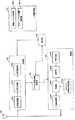
図2は、本実施形態における基地局装置の構成を示す概略ブロック図である。図2に示すように、基地局装置は、上位層処理部101、制御部102、送信部103、受信部104と送受信アンテナ105を含んで構成される。また、上位層処理部101は、無線リソース制御部1011、および、スケジューリング部1012を含んで構成される。また、送信部103は、符号化部1031、変調部1032、下りリンク参照信号生成部1033、多重部1034、無線送信部1035を含んで構成される。また、受信部104は、無線受信部1041、多重分離部1042、復調部1043、復号部1044を含んで構成される。 FIG. 2 is a schematic block diagram showing the configuration of the base station apparatus in the present embodiment. As illustrated in FIG. 2, the base station apparatus includes an upper
上位層処理部101は、媒体アクセス制御(Medium Access Control: MAC)層、パケットデータ統合プロトコル(Packet Data Convergence Protocol: PDCP)層、無線リンク制御(Radio Link Control: RLC)層、無線リソース制御(Radio Resource Control: RRC)層の処理を行なう。また、上位層処理部101は、送信部103および受信部104の制御を行なうために必要な情報を生成し、制御部102に出力する。 The upper
上位層処理部101は、端末装置の機能(UE capability)等、端末装置に関する情報を端末装置から受信する。言い換えると、端末装置は、自身の機能を基地局装置に上位層の信号で送信する。 The upper
なお、以下の説明において、端末装置に関する情報は、その端末装置が所定の機能をサポートするかどうかを示す情報、または、その端末装置が所定の機能に対する導入およびテストの完了を示す情報を含む。なお、以下の説明において、所定の機能をサポートするかどうかは、所定の機能に対する導入およびテストを完了しているかどうかを含む。例えば、その端末装置が所定の機能をサポートする場合、その端末装置が所定の機能をサポートするかどうかを示す情報、または、その端末装置が所定の機能に対する導入およびテストの完了を示す情報を送信する。その端末装置が所定の機能をサポートしない場合、その端末装置が所定の機能をサポートするかどうかを示す情報、または、その端末装置が所定の機能に対する導入およびテストの完了を示す情報を送信しない。すなわち、その端末装置が所定の機能をサポートするかどうかを示す情報、または、その端末装置が所定の機能に対する導入およびテストの完了を示す情報を送信するかどうかが、その端末装置が所定の機能をサポートするかどうかを示す。 In the following description, the information regarding the terminal device includes information indicating whether the terminal device supports a predetermined function, or information indicating that the terminal device has introduced the predetermined function and completed the test. In the following description, whether or not to support a predetermined function includes whether or not installation and testing for the predetermined function have been completed. For example, when the terminal device supports a predetermined function, information indicating whether the terminal device supports the predetermined function, or information indicating that the terminal device has introduced and tested for the predetermined function is transmitted. To do. When the terminal device does not support the predetermined function, information indicating whether the terminal device supports the predetermined function, or information indicating that the terminal device is installed and tested for the predetermined function is not transmitted. That is, whether or not the terminal device transmits information indicating whether the terminal device supports a predetermined function or whether the terminal device transmits information indicating introduction and test completion for the predetermined function is determined by the terminal device. Indicates whether to support.
例えば、端末装置が所定の機能をサポートする場合、その端末装置はその所定の機能をサポートするかどうかを示す情報(パラメータ)を送信する。端末装置が所定の機能をサポートしない場合、その端末装置はその所定の機能をサポートするかどうかを示す情報(パラメータ)を送信しない。すなわち、その所定の機能をサポートするかどうかは、その所定の機能をサポートするかどうかを示す情報(パラメータ)を送信するかどうかによって通知される。なお、所定の機能をサポートするかどうかを示す情報(パラメータ)は、1または0の1ビットを用いて通知しても良い。 For example, when a terminal device supports a predetermined function, the terminal device transmits information (parameter) indicating whether the predetermined function is supported. When the terminal device does not support the predetermined function, the terminal device does not transmit information (parameter) indicating whether or not the predetermined device is supported. That is, whether or not to support the predetermined function is notified by whether or not information (parameter) indicating whether or not to support the predetermined function is transmitted. Note that information (parameter) indicating whether or not to support a predetermined function may be notified using 1 bit of 1 or 0.
端末装置の機能には、高周波数帯をサポートしているかどうかを示すパラメータを含めることができる。なお、所定のリリースにおける端末装置で、高周波数帯のサポートが必須(Mandatory)とすることもできる。 The function of the terminal device can include a parameter indicating whether the high frequency band is supported. The terminal device in a predetermined release may be required to support high frequency bands (Mandatory).
無線リソース制御部1011は、下りリンクのPDSCHに配置される下りリンクデータ(トランスポートブロック)、システムインフォメーション、RRCメッセージ、MAC CEなどを生成し、または上位ノードから取得する。無線リソース制御部1011は、下りリンクデータを送信部103に出力し、他の情報を制御部102に出力する。また、無線リソース制御部1011は、端末装置2の各種設定情報の管理をする。 The radio
基地局装置は、高周波数帯の信号を送信したかどうかを示す情報を上位層の信号で送信する。高周波数帯での通信は、PCell、SCellの全てのセルで設定可能であっても良いし、PCellのみに設定可能であっても良いし、SCellのみに設定可能であっても良い。 The base station apparatus transmits information indicating whether or not a signal in a high frequency band has been transmitted as an upper layer signal. Communication in the high frequency band may be set in all cells of PCell and SCell, may be set only in PCell, or may be set only in SCell.
スケジューリング部1012は、物理チャネル(PDSCHおよびPUSCH)を割り当てる周波数およびサブフレーム、物理チャネル(PDSCHおよびPUSCH)の符号化率および変調方式(あるいはMCS)および送信電力などを決定する。スケジューリング部1012は、決定した情報を制御部102に出力する。
なお、基地局装置は、第2のフレーム構造を用いる場合、UEの割当ては、リソースブロック毎、および/または、リソースブロックセット毎、および/または、サブフレーム毎、および/または、サブフレームセット毎に行なう。 When the base station apparatus uses the second frame structure, UE allocation is performed for each resource block and / or for each resource block set and / or for each subframe and / or for each subframe set. To do.
スケジューリング部1012は、スケジューリング結果に基づき、物理チャネル(PDSCHおよびPUSCH)のスケジューリングに用いられる情報を生成する。スケジューリング部1012は、生成した情報を制御部102に出力する。 The
なお、第2のフレーム構造では、第1のフレーム構造よりも、大きな値のMCSを用いることも可能である。つまり、第2のフレーム構造では、第1のフレーム構造を用いる場合よりも、高いビットレートで通信可能である。また、第2のフレーム構造では、第1のフレーム構造よりも、1UEに対して多くのコードワードを割り当てることもできる。また、第2のフレーム構造では、第1のフレーム構造を用いる場合よりも、高いランク数で送信することもできる。また、第2のフレーム構造では、第1のフレーム構造を用いる場合よりも、多くのアンテナポートに対応することができる。 In the second frame structure, it is possible to use a larger value of MCS than in the first frame structure. That is, in the second frame structure, communication can be performed at a higher bit rate than in the case where the first frame structure is used. In the second frame structure, more codewords can be assigned to one UE than in the first frame structure. Further, in the second frame structure, transmission can be performed with a higher rank number than in the case of using the first frame structure. Further, the second frame structure can cope with a larger number of antenna ports than when the first frame structure is used.
制御部102は、上位層処理部101から入力された情報に基づいて、送信部103および受信部104の制御を行なう制御信号を生成する。また、制御部102は、上位層処理部101から入力された情報に基づいて、MCSを決定する。また、制御部102は、上位層処理部101から入力された情報に基づいて、コードワード数を決定する。また、制御部102は、上位層処理部101から入力された情報に基づいて、レイヤ数、アンテナポート番号、スクランブリングアイデンティティ(スクランブリング識別子、scrambling identity)を決定する。 The
制御部102は、上位層処理部101から入力された情報に基づいて、下りリンク制御情報を生成し、送信部103に出力する。基地局装置がプライマリセルである場合は、セカンダリセルの上位層の設定情報を下りリンク制御情報に含めても良い。 The
送信部103は、制御部102から入力された制御信号に従って、下りリンク参照信号を生成し、上位層処理部101から入力されたHARQインディケータ、下りリンク制御情報、および、下りリンクデータを、符号化および変調し、PHICH、PDCCH、EPDCCH、PDSCH、および下りリンク参照信号を多重して、送受信アンテナ105を介して端末装置2に信号を送信する。なお、基地局装置は、第2のフレーム構造を用いる場合、少なくともPDSCHを多重し、下りリンク制御情報を多重しないようにすることができる。また、第2のフレーム構造では、第1のフレーム構造と比べて、下りリンク参照信号の周波数間隔/時間間隔を広くすることができる。また、基地局装置は、第2のフレーム構造に割り当てた信号の制御情報は、第1のフレーム構造を用いて送信することができる。 The
符号化部1031は、上位層処理部101から入力されたHARQインディケータ、下りリンク制御情報、および下りリンクデータを、ブロック符号化、畳み込み符号化、ターボ符号化等の予め定められた符号化方式を用いて符号化を行なう、または無線リソース制御部1011が決定した符号化方式を用いて符号化を行なう。変調部1032は、符号化部1031から入力された符号化ビットをBPSK(Binary Phase Shift Keying)、QPSK(quadrature Phase Shift Keying)、16QAM(quadrature amplitude modulation)、64QAM、256QAM等の予め定められた、または無線リソース制御部1011が決定した変調方式で変調する。 The
下りリンク参照信号生成部1033は、基地局装置1を識別するための物理セル識別子(PCI)などを基に予め定められた規則で求まる、端末装置2が既知の系列を下りリンク参照信号として生成する。また、下りリンク参照信号生成部1033は、スクランブリングアイデンティティに基づいてDMRSを生成することができる。 The downlink reference
多重部1034は、変調された各チャネルの変調シンボルと生成された下りリンク参照信号と下りリンク制御情報とを多重する。つまり、多重部1034は、変調された各チャネルの変調シンボルと生成された下りリンク参照信号と下りリンク制御情報とをリソースエレメントに配置する。 The
無線送信部1035は、多重された変調シンボルなどを逆高速フーリエ変換(Inverse Fast Fourier Transform: IFFT)して、OFDM方式の変調を行ない、OFDM変調されたOFDMシンボルにサイクリックプリフィックス(Cyclic Prefix: CP)を付加し、ベースバンドのディジタル信号を生成する。無線送信部1035は、フィルタリング、DA(Digital-to-Analog)変換、周波数変換、電力増幅等を用いることで、生成したベースバンドのディジタル信号を所望帯域のアナログ信号に変換する。無線送信部1035は、生成したアナログ信号を送受信アンテナ105に出力して送信する。 The
基地局装置は、送信する周波数帯によって、第1のフレーム構造を用いるか、第2のフレーム構造を用いるかを切り替える。 The base station apparatus switches between using the first frame structure or the second frame structure depending on the frequency band to be transmitted.
基地局装置は、第1のフレーム構造を用いる場合、無線送信部1035が生成するOFDMシンボルのサブキャリア間隔を、例えば15kHzとすることができる。基地局装置は、第2のフレーム構造を用いる場合、無線送信部1035が生成するOFDMシンボルのサブキャリア間隔を、第1のフレーム構造の場合のサブキャリア間隔より広げることができる。このようにすると、OFDMシンボル長が短くなるため、位相雑音の影響を低減することができる。また、端末装置が移動している場合の性能を向上させることができる。基地局装置が第2のフレーム構造を用いる場合、無線送信部1035が生成するOFDMシンボルのサブキャリア間隔は、例えば75kHzとすることができる。このようにすると、第2のフレーム構造におけるOFDMシンボル長は、第1のフレーム構造におけるOFDMシンボル長の5分の1となる。第2のフレーム構造におけるOFDMシンボルに付加するCP長は第1のフレーム構造におけるCP長の5分の1としても良い。基地局装置は、第1のフレーム構造を用いる場合、10msを1単位とするフレーム、1msを1単位とするサブフレームを用いることができる。基地局装置は、第2のフレーム構造を用いる場合、無線送信部1035が生成するOFDMシンボルのサブキャリア間隔を75kHzとした場合も同じフレーム長、サブフレーム長を用いることができる。この場合、第2のフレーム構造におけるフレーム内およびサブフレーム内のOFDMシンボル数は、第1のフレーム構造の場合と比べて5倍となる。また、第1のフレーム構造と第2のフレーム構造の場合で、サブフレームあたりのOFDMシンボル数を同じ値にすることができる。この場合、第2のフレーム構造におけるサブフレームは、0.2ミリ秒を1単位とする。このとき、基地局装置は、1ミリ秒を1単位とする別の用語を用いても良い。つまり、例えば、基地局装置は、第2のフレーム構造を用いる場合、1ミリ秒単位のサブフレームグループを用いることができる。サブフレーム長が0.2ミリ秒の場合、サブフレームグループは、5サブフレームで構成される。 When using the first frame structure, the base station apparatus can set the subcarrier interval of the OFDM symbol generated by the
基地局装置が第2のフレーム構造を用いる場合、無線送信部1035が生成するOFDMシンボルの帯域幅は、第1のフレーム構造を用いる場合の無線送信部1035が生成するOFDMシンボルの帯域幅より広げることができる。このようにすると、高周波数帯を用いる場合に広帯域で通信できるようになり、端末装置への通信のスループットを向上させることができる。 When the base station apparatus uses the second frame structure, the bandwidth of the OFDM symbol generated by the
基地局装置は、第1のフレーム構造を用いる場合、12個のサブキャリアと14個のOFDMシンボルを1単位とするリソースブロックを用いることができる。サブキャリア間隔が15kHzの場合、システム帯域幅が最大20MHzであるため、周波数方向の最大RB数は100となる。一方、基地局装置が第2のフレーム構造を用いる場合、無線送信部1035が生成するOFDMシンボルの帯域幅が、第1のフレーム構造を用いる場合のOFDMシンボルより広い場合、第2のフレーム構造の場合のOFDMシンボルの取り得るサブキャリア数が増加することがある。例えば、基地局装置が第2のフレーム構造を用いる場合、OFDMシンボルのサブキャリア間隔を75kHzとし、システム帯域幅を最大500MHzとすると、サブキャリア数は6000となる。第2のフレーム構造では、リソースブロックを、60個のサブキャリアと14個のOFDMシンボルを1単位としても良い。このようにすると、周波数方向の最大RB数は100となり、第1のフレーム構造と一致する。あるいは、リソースブロックの定義は第1のフレーム構造と同一とし、周波数方向の最大RB数を500としても良い。あるいは、別の用語を用いて、プライマリ基地局装置1Aの用いるリソースブロックと異なるリソースブロックを定義しても良い。例えば、第2のフレーム構造におけるリソースブロックは、第1のフレーム構造のリソースブロックと同じサイズである複数のサブリソースブロックから構成することができる。別の言い方では、第2のフレーム構造のリソースブロックは、第1のフレーム構造のリソースブロックと同じサイズであり、第2のフレーム構造は、複数のリソースブロックで構成されるリソースブロックセットを有する。 When using the first frame structure, the base station apparatus can use a resource block having 12 subcarriers and 14 OFDM symbols as a unit. When the subcarrier interval is 15 kHz, the maximum system bandwidth is 20 MHz, so the maximum number of RBs in the frequency direction is 100. On the other hand, when the base station apparatus uses the second frame structure, when the bandwidth of the OFDM symbol generated by the
受信部104は、制御部102から入力された制御信号に従って、送受信アンテナ105を介して端末装置2から受信した受信信号を分離、復調、復号し、復号した情報を上位層処理部101に出力する。 The receiving
無線受信部1041は、周波数変換、フィルタリング、AD(Analog-to-Digital)変換、振幅制御等を用いることで、送受信アンテナ105を介して受信された上りリンクの信号をベースバンドのディジタル信号に変換する。 The
無線受信部1041は、変換したディジタル信号からCPに相当する部分を除去する。無線受信部1041は、CPを除去した信号に対して高速フーリエ変換(Fast Fourier Transform: FFT)を行ない、周波数領域の信号を抽出し多重分離部1042に出力する。
多重分離部1042は、無線受信部1041から入力された信号をPUCCH、PUSCH、上りリンク参照信号などの信号に分離する。なお、この分離は、予め基地局装置1が無線リソース制御部1011で決定し、各端末装置2に通知した上りリンクグラントに含まれる無線リソースの割り当て情報に基づいて行なわれる。 The
また、多重分離部1042は、PUCCHとPUSCHの伝搬路の補償を行なう。また、多重分離部1042は、上りリンク参照信号を分離する。 In addition,
復調部1043は、PUSCHを逆離散フーリエ変換(Inverse Discrete Fourier Transform: IDFT)し、変調シンボルを取得し、PUCCHとPUSCHの変調シンボルそれぞれに対して、BPSK、QPSK、16QAM、64QAM、256QAM等の予め定められた、または自装置が端末装置2各々に上りリンクグラントで予め通知した変調方式を用いて受信信号の復調を行なう。なお、逆離散フーリエ変換は、PUSCHのサブキャリア数に応じた逆高速フーリエ変換であっても良い。 The
復号部1044は、復調されたPUCCHとPUSCHの符号化ビットを、予め定められた符号化方式の、予め定められた、または自装置が端末装置2に上りリンクグラントで予め通知した符号化率で復号を行ない、復号した上りリンクデータと、上りリンク制御情報を上位層処理部101へ出力する。PUSCHが再送信の場合は、復号部1044は、上位層処理部101から入力されるHARQバッファに保持している符号化ビットと、復調された符号化ビットを用いて復号を行なう。 The
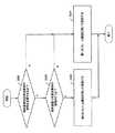
図3は、制御部102が端末装置2の下りリンク制御情報を設定する処理の流れを示す図である。 FIG. 3 is a diagram illustrating a flow of processing in which the
S301において、制御部102は、端末装置から受信する端末装置に関する情報を用いて、端末装置が高周波数帯の信号を受信できるかどうかを判断する。 In step S <b> 301, the
S302において、制御部102は、端末装置に高周波数帯の通信を行なうか否かを判断する。 In S302, the
S303において、基地局装置は、第2のフレーム構造を用いて送信信号を生成し、端末装置に送信する。 In S303, the base station apparatus generates a transmission signal using the second frame structure and transmits the transmission signal to the terminal apparatus.
S304において、基地局装置は、第1のフレーム構造を用いて送信信号を生成し、端末装置に送信する。 In S304, the base station apparatus generates a transmission signal using the first frame structure and transmits the transmission signal to the terminal apparatus.
図4は、本実施形態における端末装置の構成を示す概略ブロック図である。図4に示すように、端末装置は、上位層処理部201、制御部202、送信部203、受信部204、チャネル状態情報生成部205と送受信アンテナ206を含んで構成される。また、上位層処理部201は、無線リソース制御部2011、およびスケジューリング情報解釈部2012を含んで構成される。また、送信部203は、符号化部2031、変調部2032、上りリンク参照信号生成部2033、多重部2034、無線送信部2035を含んで構成される。また、受信部204は、無線受信部2041、多重分離部2042、信号検出部2043を含んで構成される。 FIG. 4 is a schematic block diagram showing the configuration of the terminal device in the present embodiment. As illustrated in FIG. 4, the terminal device includes an upper
上位層処理部201は、ユーザの操作等によって生成された上りリンクデータ(トランスポートブロック)を、送信部203に出力する。また、上位層処理部201は、媒体アクセス制御(Medium Access Control: MAC)層、パケットデータ統合プロトコル(Packet Data Convergence Protocol: PDCP)層、無線リンク制御(Radio Link Control: RLC)層、無線リソース制御(Radio Resource Control: RRC)層の処理を行なう。 The upper
上位層処理部201は、自端末装置がサポートしている端末装置の機能を示す情報を、送信部203に出力する。 The upper
無線リソース制御部2011は、自端末装置の各種設定情報の管理をする。また、無線リソース制御部2011は、上りリンクの各チャネルに配置される情報を生成し、送信部203に出力する。 The radio
スケジューリング情報解釈部2012は、受信部204を介して受信した下りリンク制御情報を解釈し、スケジューリング情報を判定する。また、スケジューリング情報解釈部2012は、スケジューリング情報に基づき、受信部204、および送信部203の制御を行なうために制御情報を生成し、制御部202に出力する。 The scheduling
制御部202は、上位層処理部201から入力された情報に基づいて、受信部204、および送信部203の制御を行なう制御信号を生成する。制御部202は、生成した制御信号を受信部204、および送信部203に出力して受信部204、および送信部203の制御を行なう。制御部202は、端末情報等を含む上りリンク制御情報および上りリンクデータを送信部203に出力する。ここで、端末情報は端末装置が高周波数帯の信号を復調する機能を有するか否かを示す情報を含む。 The
制御部202は、受信した信号が高周波数帯の信号かどうかを示す設定情報を、基地局装置から上位層を介して受信し、第1のフレーム構造を用いて復調するか、第2のフレーム構造を用いて復調するかを示す制御情報を受信部204に出力する。 The
制御部202は、チャネル状態情報生成部205が生成したCSIを基地局装置に送信するように送信部203を制御する。 The
受信部204は、制御部202から入力された制御信号に従って、送受信アンテナ206を介して基地局装置から受信した受信信号を、分離、復調、復号し、復号した情報を上位層処理部201に出力する。受信部204は、制御部202から入力された制御信号に従って、第1のフレーム構造または第2のフレーム構造に対応する復調を行なう。 The receiving
無線受信部2041は、周波数変換、フィルタリング、AD変換、振幅制御等を用いることで、送受信アンテナ206を介して受信された下りリンクの信号をベースバンドのディジタル信号に変換する。 The
また、無線受信部2041は、変換したディジタル信号からCPに相当する部分を除去し、CPを除去した信号に対して高速フーリエ変換を行ない、周波数領域の信号を抽出する。 Also, the
多重分離部2042は、抽出した信号をPHICH、PDCCH、EPDCCH、PDSCH、および/または下りリンク参照信号に、それぞれ分離する。また、多重分離部2042は、チャネル測定から得られた所望信号のチャネルの推定値に基づいて、PHICH、PDCCH、およびEPDCCHのチャネルの補償を行ない、下りリンク制御情報を検出し、制御部202に出力する。なお、受信信号が第2のフレーム構造を用いて送信された信号であった場合で、第2のフレーム構造では下りリンク制御情報が送信されない場合、多重分離部2042は、下りリンク制御情報の検出は行なわない。また、制御部202は、PDSCHおよび所望信号のチャネル推定値を信号検出部2043に出力する。なお、チャネル推定は制御部202から入力される自端末装置宛のレイヤ数、アンテナポート番号、スクランブリングアイデンティティに基づいて行なう。 The
信号検出部2043は、PDSCH、およびチャネル推定値を用いて、下りリンクデータ(トランスポートブロック)を検出し、上位層処理部201に出力する。 The
送信部203は、制御部202から入力された制御信号に従って、上りリンク参照信号を生成し、上位層処理部201から入力された上りリンクデータ(トランスポートブロック)を符号化および変調し、PUCCH、PUSCH、および生成した上りリンク参照信号を多重し、送受信アンテナ206を介して基地局装置に送信する。なお、第2のフレーム構造が下りリンクのみに用いられる場合、送信部203は、第1のフレーム構造を用いて上りリンク信号を生成する。 The
符号化部2031は、上位層処理部201から入力された上りリンク制御情報を畳み込み符号化、ブロック符号化等の符号化を行なう。また、符号化部2031は、PUSCHのスケジューリングに用いられる情報に基づきターボ符号化を行なう。 The
変調部2032は、符号化部2031から入力された符号化ビットをBPSK、QPSK、16QAM、64QAM等の下りリンク制御情報で通知された変調方式または、チャネル毎に予め定められた変調方式で変調する。 The
上りリンク参照信号生成部2033は、基地局装置1を識別するための物理セル識別子(physical cell identity: PCI、Cell IDなどと称される)、上りリンク参照信号を配置する帯域幅、上りリンクグラントで通知されたサイクリックシフト、DMRSシーケンスの生成に対するパラメータの値などを基に、予め定められた規則(式)で求まる系列を生成する。 The uplink reference
多重部2034は、制御部202から入力された制御信号に従って、PUSCHの変調シンボルを並列に並び替えてから離散フーリエ変換(Discrete Fourier Transform: DFT)する。また、多重部2034は、PUCCHとPUSCHの信号と生成した上りリンク参照信号を送信アンテナポート毎に多重する。つまり、多重部2034は、PUCCHとPUSCHの信号と生成した上りリンク参照信号を送信アンテナポート毎にリソースエレメントに配置する。なお、離散フーリエ変換はPUCCHやPUSCHのサブキャリア数に応じた高速フーリエ変換でも良い。 The
無線送信部2035は、多重された信号を逆高速フーリエ変換して、SC−FDMA方式の変調を行ない、SC−FDMAシンボルを生成し、生成されたSC−FDMAシンボルにCPを付加し、ベースバンドのディジタル信号を生成する。無線送信部2035は、フィルタリング、DA変換、周波数変換、電力増幅等を用いることで、生成したベースバンドのディジタル信号を所望帯域のアナログ信号に変換する。無線送信部2035は、生成したアナログ信号を送受信アンテナ206に出力して送信する。
図5は、多重分離部2042と信号検出部2043の処理の流れを示す図である。 FIG. 5 is a diagram illustrating a processing flow of the
S501において、端末装置は、基地局装置から上位層で受信する高周波数帯の通信の指示の有無を判定する。高周波数帯の通信の指示を検出した場合、S502へ進む。高周波数帯の通信の指示を検出しなかった場合、S503へ進む。 In step S501, the terminal apparatus determines whether there is an instruction for communication in a high frequency band received from the base station apparatus in an upper layer. When an instruction for communication in the high frequency band is detected, the process proceeds to S502. If an instruction for communication in the high frequency band is not detected, the process proceeds to S503.
S502において、信号検出部2043は、第2のフレーム構造を用いて復調を行なう。 In S502, the
S503において、信号検出部2043は、第1のフレーム構造を用いて復調を行なう。 In S503, the
上述のような処理を行なうことによって、広帯域の信号を受信することができ、スループットを改善することができる。 By performing the processing as described above, a wideband signal can be received, and the throughput can be improved.
なお、本発明に係る基地局装置および端末装置で動作するプログラムは、本発明に関わる上記実施形態の機能を実現するように、CPU等を制御するプログラム(コンピュータを機能させるプログラム)である。そして、これら装置で取り扱われる情報は、その処理時に一時的にRAMに蓄積され、その後、各種ROMやHDDに格納され、必要に応じてCPUによって読み出し、修正・書き込みが行なわれる。プログラムを格納する記録媒体としては、半導体媒体(例えば、ROM、不揮発性メモリカード等)、光記録媒体(例えば、DVD、MO、MD、CD、BD等)、磁気記録媒体(例えば、磁気テープ、フレキシブルディスク等)等のいずれであっても良い。また、ロードしたプログラムを実行することにより、上述した実施形態の機能が実現されるだけでなく、そのプログラムの指示に基づき、オペレーティングシステムあるいは他のアプリケーションプログラム等と共同して処理することにより、本発明の機能が実現される場合もある。 Note that the program that operates in the base station apparatus and the terminal apparatus according to the present invention is a program (a program that causes a computer to function) that controls the CPU and the like so as to realize the functions of the above-described embodiments according to the present invention. Information handled by these devices is temporarily stored in the RAM at the time of processing, then stored in various ROMs and HDDs, read out by the CPU, and corrected and written as necessary. As a recording medium for storing the program, a semiconductor medium (for example, ROM, nonvolatile memory card, etc.), an optical recording medium (for example, DVD, MO, MD, CD, BD, etc.), a magnetic recording medium (for example, magnetic tape, Any of a flexible disk etc. may be sufficient. In addition, by executing the loaded program, not only the functions of the above-described embodiment are realized, but also based on the instructions of the program, the processing is performed in cooperation with the operating system or other application programs. The functions of the invention may be realized.
また、市場に流通させる場合には、可搬型の記録媒体にプログラムを格納して流通させたり、インターネット等のネットワークを介して接続されたサーバコンピュータに転送したりすることができる。この場合、サーバコンピュータの記憶装置も本発明に含まれる。また、上述した実施形態における端末装置および基地局装置の一部、または全部を典型的には集積回路であるLSIとして実現しても良い。受信装置の各機能ブロックは個別にチップ化しても良いし、一部、または全部を集積してチップ化しても良い。各機能ブロックを集積回路化した場合に、それらを制御する集積回路制御部が付加される。 In addition, when distributing to the market, the program can be stored and distributed in a portable recording medium, or transferred to a server computer connected via a network such as the Internet. In this case, the storage device of the server computer is also included in the present invention. Moreover, you may implement | achieve part or all of the terminal device and base station apparatus in embodiment mentioned above as LSI which is typically an integrated circuit. Each functional block of the receiving apparatus may be individually chipped, or a part or all of them may be integrated into a chip. When each functional block is integrated, an integrated circuit controller for controlling them is added.
また、集積回路化の手法はLSIに限らず専用回路、または汎用プロセッサで実現しても良い。また、半導体技術の進歩によりLSIに代替する集積回路化の技術が出現した場合、当該技術による集積回路を用いることも可能である。 Further, the method of circuit integration is not limited to LSI, and may be realized by a dedicated circuit or a general-purpose processor. In addition, when an integrated circuit technology that replaces LSI appears due to progress in semiconductor technology, an integrated circuit based on the technology can also be used.
なお、本願発明は上述の実施形態に限定されるものではない。本願発明の端末装置は、移動局装置への適用に限定されるものではなく、屋内外に設置される据え置き型、または非可動型の電子機器、例えば、AV機器、キッチン機器、掃除・洗濯機器、空調機器、オフィス機器、自動販売機、その他生活機器などに適用出来ることは言うまでもない。 In addition, this invention is not limited to the above-mentioned embodiment. The terminal device of the present invention is not limited to application to a mobile station device, but is a stationary or non-movable electronic device installed indoors or outdoors, such as AV equipment, kitchen equipment, cleaning / washing equipment Needless to say, it can be applied to air conditioning equipment, office equipment, vending machines, and other daily life equipment.
以上、この発明の実施形態を、図面を参照して詳述してきたが、具体的な構成はこの実施形態に限られるものではなく、この発明の要旨を逸脱しない範囲の設計等も請求の範囲に含まれる。 The embodiment of the present invention has been described in detail with reference to the drawings. However, the specific configuration is not limited to this embodiment, and the design and the like within the scope of the present invention are also within the scope of the claims. include.
本発明は、端末装置、基地局装置および通信方法に用いて好適である。 The present invention is suitable for use in a terminal device, a base station device, and a communication method.
なお、本国際出願は、2014年9月19日に出願した日本国特許出願第2014−190871号に基づく優先権を主張するものであり、日本国特許出願第2014−190871号の全内容を本国際出願に援用する。 This international application claims priority based on Japanese Patent Application No. 2014-190871 filed on September 19, 2014, and the entire contents of Japanese Patent Application No. 2014-190871 are hereby incorporated by reference. Included in international applications.
1 基地局装置
2 端末装置
1−1 カバレッジ
101 上位層処理部
102 制御部
103 送信部
104 受信部
105 送受信アンテナ
1011 無線リソース制御部
1012 スケジューリング部
1031 符号化部
1032 変調部
1033 下りリンク参照信号生成部
1034 多重部
1035 無線送信部
1041 無線受信部
1042 多重分離部
1043 復調部
1044 復号部
201 上位層処理部
202 制御部
203 送信部
204 受信部
205 チャネル状態情報生成部
206 送受信アンテナ
2011 無線リソース制御部
2012 スケジューリング情報解釈部
2031 符号化部
2032 変調部
2033 上りリンク参照信号生成部
2034 多重部
2035 無線送信部
2041 無線受信部
2042 多重分離部
2043 信号検出部DESCRIPTION OF
Claims (10)
Translated fromJapanese前記変調シンボルを用いた第1のOFDM(Orthogonal frequency division multiplexing)シンボルの生成および第1のフレーム構造による前記第1のOFDMシンボルの送信と、前記変調シンボルを用いた第2のOFDMシンボルの生成および第2のフレーム構造による前記第2のOFDMシンボルの送信のいずれかを選択的に行う送信部と、を備え、Generation of a first orthogonal frequency multiplexing (OFDM) symbol using the modulation symbol and transmission of the first OFDM symbol according to a first frame structure; generation of a second OFDM symbol using the modulation symbol; A transmitter that selectively performs transmission of the second OFDM symbol according to a second frame structure, and
前記第1のフレーム構造に含まれる第1のサブフレームは、前記第1のOFDMシンボルを14個備え、前記第1のOFDMシンボルのサブキャリア間隔は、15kHzであり、The first subframe included in the first frame structure includes 14 first OFDM symbols, and the subcarrier interval of the first OFDM symbol is 15 kHz,
前記第2のフレーム構造に含まれる第2のサブフレームは、前記第2のOFDMシンボルを14個備え、前記第2のOFDMシンボルのサブキャリア間隔は、15kHzの所定数倍であり、The second subframe included in the second frame structure includes 14 second OFDM symbols, and the subcarrier interval of the second OFDM symbol is a predetermined multiple of 15 kHz,
前記所定数は自然数であり、The predetermined number is a natural number;
前記第2のフレーム構造は、サブフレームグループを備え、前記サブフレームグループは、前記所定数の前記第2のサブフレームを備え、The second frame structure comprises a subframe group, the subframe group comprising the predetermined number of the second subframes;
前記第1のサブフレームの長さは、1msであり、前記サブフレームグループの長さは、1msである、The length of the first subframe is 1 ms, and the length of the subframe group is 1 ms.
通信装置。Communication device.
請求項1に記載の通信装置。The communication apparatus according to claim 1.
前記制御情報は、自装置が所定の周波数帯をサポートするか否かを示し、The control information indicates whether the device supports a predetermined frequency band,
自装置が前記所定の周波数帯をサポートする場合、前記送信部は、前記変調シンボルを用いた前記第2のOFDMシンボルの生成と、前記第2のフレーム構造による前記第2のOFDMシンボルの送信と、を行う、When the own apparatus supports the predetermined frequency band, the transmission unit generates the second OFDM symbol using the modulation symbol, and transmits the second OFDM symbol according to the second frame structure. ,I do,
請求項1又は請求項2に記載の通信装置。The communication apparatus according to claim 1 or 2.
請求項1から請求項3のいずれか一項に記載の通信装置。The communication apparatus according to any one of claims 1 to 3.
前記第1のOFDMシンボルの復調と、前記第2のOFDMシンボルの復調のいずれかを選択的に行う復調部と、を備え、A demodulator that selectively performs demodulation of the first OFDM symbol and demodulation of the second OFDM symbol,
前記第1のフレーム構造に含まれる第1のサブフレームは、前記第1のOFDMシンボルを14個備え、前記第1のOFDMシンボルのサブキャリア間隔は15kHzであり、The first subframe included in the first frame structure includes 14 first OFDM symbols, and the subcarrier interval of the first OFDM symbol is 15 kHz,
前記第2のフレーム構造に含まれる第2のサブフレームは、前記第2のOFDMシンボルを14個備え、前記第2のOFDMシンボルのサブキャリア間隔は15kHzの所定数倍であり、The second subframe included in the second frame structure includes 14 second OFDM symbols, and the subcarrier interval of the second OFDM symbol is a predetermined multiple of 15 kHz,
前記所定数は自然数であり、The predetermined number is a natural number;
前記第2のフレーム構造は、サブフレームグループを備え、前記サブフレームグループは、前記所定数の前記第2のサブフレームを備え、 The second frame structure comprises a subframe group, the subframe group comprising the predetermined number of the second subframes;
前記第1のサブフレームの長さは、1msであり、前記サブフレームグループの長さは、1msである、The length of the first subframe is 1 ms, and the length of the subframe group is 1 ms.
通信装置。Communication device.
請求項5に記載の通信装置。The communication device according to claim 5.
前記制御情報は、前記通信装置とは異なる他の通信装置が所定の周波数帯をサポートするか否かを示し、The control information indicates whether another communication device different from the communication device supports a predetermined frequency band,
前記他の通信装置が前記所定の周波数帯をサポートする場合、前記受信部は、前記第2のフレーム構造による前記第2のOFDMシンボルの受信を行う、When the other communication device supports the predetermined frequency band, the receiving unit receives the second OFDM symbol by the second frame structure.
請求項5又は請求項6に記載の通信装置。The communication apparatus according to claim 5 or 6.
請求項5から請求項7のいずれか一項に記載の通信装置。The communication apparatus according to any one of claims 5 to 7.
符号化ビットを用いて変調シンボルを生成し、Generate modulation symbols using coded bits;
前記変調シンボルを用いた第1のOFDM(Orthogonal frequency division multiplexing)シンボルの生成および第1のフレーム構造による前記第1のOFDMシンボルの送信と、前記変調シンボルを用いた第2のOFDMシンボルの生成および第2のフレーム構造による前記第2のOFDMシンボルの送信のいずれかを選択的に行い、Generation of a first orthogonal frequency multiplexing (OFDM) symbol using the modulation symbol and transmission of the first OFDM symbol according to a first frame structure; generation of a second OFDM symbol using the modulation symbol; Selectively performing transmission of the second OFDM symbol according to a second frame structure;
前記第1のフレーム構造に含まれる第1のサブフレームは、前記第1のOFDMシンボルを14個備え、前記第1のOFDMシンボルのサブキャリア間隔は、15kHzであり、The first subframe included in the first frame structure includes 14 first OFDM symbols, and the subcarrier interval of the first OFDM symbol is 15 kHz,
前記第2のフレーム構造に含まれる第2のサブフレームは、前記第2のOFDMシンボルを14個備え、前記第2のOFDMシンボルのサブキャリア間隔は、15kHzの所定数倍であり、The second subframe included in the second frame structure includes 14 second OFDM symbols, and the subcarrier interval of the second OFDM symbol is a predetermined multiple of 15 kHz,
前記所定数は自然数であり、The predetermined number is a natural number;
前記第2のフレーム構造は、サブフレームグループを備え、前記サブフレームグループは、前記所定数の前記第2のサブフレームを備え、The second frame structure comprises a subframe group, the subframe group comprising the predetermined number of the second subframes;
前記第1のサブフレームの長さは、1msであり、前記サブフレームグループの長さは、1msである、The length of the first subframe is 1 ms, and the length of the subframe group is 1 ms.
通信方法。Communication method.
第1のフレーム構造による第1のOFDM(Orthogonal frequency division multiplexing)シンボルの受信と、第2のフレーム構造による第2のOFDMシンボルの受信のいずれかを選択的に行い、Selectively performing reception of a first OFDM (Orthogonal frequency division multiplexing) symbol according to the first frame structure and reception of a second OFDM symbol according to the second frame structure;
前記第1のOFDMシンボルの復調と、前記第2のOFDMシンボルの復調のいずれかを選択的に行い、Selectively performing either demodulation of the first OFDM symbol or demodulation of the second OFDM symbol;
前記第1のフレーム構造に含まれる第1のサブフレームは、前記第1のOFDMシンボルを14個備え、前記第1のOFDMシンボルのサブキャリア間隔は、15kHzであり、The first subframe included in the first frame structure includes 14 first OFDM symbols, and the subcarrier interval of the first OFDM symbol is 15 kHz,
前記第2のフレーム構造に含まれる第2のサブフレームは、前記第2のOFDMシンボルを14個備え、前記第2のOFDMシンボルのサブキャリア間隔は、15kHzの所定数倍であり、The second subframe included in the second frame structure includes 14 second OFDM symbols, and the subcarrier interval of the second OFDM symbol is a predetermined multiple of 15 kHz,
前記所定数は自然数であり、The predetermined number is a natural number;
前記第2のフレーム構造は、サブフレームグループを備え、前記サブフレームグループは、前記所定数の前記第2のサブフレームを備え、The second frame structure comprises a subframe group, the subframe group comprising the predetermined number of the second subframes;
前記第1のサブフレームの長さは、1msであり、前記サブフレームグループの長さは、1msである、The length of the first subframe is 1 ms, and the length of the subframe group is 1 ms.
通信方法。Communication method.
Applications Claiming Priority (3)
| Application Number | Priority Date | Filing Date | Title |
|---|---|---|---|
| JP2014190871 | 2014-09-19 | ||
| JP2014190871 | 2014-09-19 | ||
| PCT/JP2015/074390WO2016043020A1 (en) | 2014-09-19 | 2015-08-28 | Terminal device, base station device and communication method |
Publications (2)
| Publication Number | Publication Date |
|---|---|
| JPWO2016043020A1 JPWO2016043020A1 (en) | 2017-08-10 |
| JP6555827B2true JP6555827B2 (en) | 2019-08-07 |
Family
ID=55533061
Family Applications (1)
| Application Number | Title | Priority Date | Filing Date |
|---|---|---|---|
| JP2016548812AActiveJP6555827B2 (en) | 2014-09-19 | 2015-08-28 | Communication device and communication method |
Country Status (3)
| Country | Link |
|---|---|
| US (1) | US10630599B2 (en) |
| JP (1) | JP6555827B2 (en) |
| WO (1) | WO2016043020A1 (en) |
Families Citing this family (13)
| Publication number | Priority date | Publication date | Assignee | Title |
|---|---|---|---|---|
| US10862634B2 (en) | 2014-03-07 | 2020-12-08 | Huawei Technologies Co., Ltd. | Systems and methods for OFDM with flexible sub-carrier spacing and symbol duration |
| US10051641B2 (en)* | 2014-03-20 | 2018-08-14 | Sharp Kabushiki Kaisha | Terminal apparatus, base station apparatus, and integrated circuit |
| US9985760B2 (en) | 2015-03-31 | 2018-05-29 | Huawei Technologies Co., Ltd. | System and method for an adaptive frame structure with filtered OFDM |
| US10333678B2 (en)* | 2015-05-29 | 2019-06-25 | Huawei Technologies Co., Ltd. | Systems and methods of adaptive frame structure for time division duplex |
| JP2018207137A (en)* | 2015-11-02 | 2018-12-27 | シャープ株式会社 | Base station apparatus, terminal apparatus and communication method |
| WO2017183252A1 (en) | 2016-04-21 | 2017-10-26 | ソニー株式会社 | Terminal apparatus, base station apparatus, and communication method |
| JP6961591B2 (en)* | 2016-07-15 | 2021-11-05 | 株式会社Nttドコモ | Terminals, wireless communication methods, base stations and wireless communication systems |
| CN111935814B (en)* | 2016-07-18 | 2021-11-16 | 中兴通讯股份有限公司 | Method and device for sending and receiving synchronization signal and transmission system |
| JP2018026662A (en) | 2016-08-09 | 2018-02-15 | ソニー株式会社 | Communication device, communication method, and program |
| KR20180081669A (en)* | 2017-01-06 | 2018-07-17 | 주식회사 케이티 | Apparatus and method of common control information transmission for NR(New Radio) |
| JP2018121174A (en)* | 2017-01-24 | 2018-08-02 | 株式会社Kddi総合研究所 | Control device, communication device, control method, and program |
| US10368353B2 (en)* | 2017-01-27 | 2019-07-30 | Qualcomm Incorporated | Adaptive subcarrier spacing configuration |
| US11196512B2 (en)* | 2018-06-29 | 2021-12-07 | Qualcomm Incorporated | Resolving decodability for subsequent transmissions whose throughput exceeds a threshold |
Family Cites Families (10)
| Publication number | Priority date | Publication date | Assignee | Title |
|---|---|---|---|---|
| US9137075B2 (en)* | 2007-02-23 | 2015-09-15 | Telefonaktiebolaget Lm Ericsson (Publ) | Subcarrier spacing identification |
| US8687537B2 (en) | 2008-07-08 | 2014-04-01 | Sharp Kabushiki Kaisha | Communication system, reception device, and communication method |
| US8934447B2 (en)* | 2010-03-05 | 2015-01-13 | Lg Electronics Inc. | Method and apparatus for communication with a network in a wireless communication system |
| JP6311600B2 (en) | 2012-03-23 | 2018-04-18 | 住友電気工業株式会社 | SETTING DEVICE, COMMUNICATION CONTROL METHOD, AND COMMUNICATION CONTROL PROGRAM |
| JP6042127B2 (en) | 2012-07-25 | 2016-12-14 | 株式会社Nttドコモ | Mobile terminal apparatus and base station apparatus |
| US9521544B2 (en)* | 2012-08-03 | 2016-12-13 | Telefonaktiebolaget Lm Ericsson (Publ) | Availability of modes of communication |
| KR101660750B1 (en)* | 2012-10-22 | 2016-09-28 | 엘지전자 주식회사 | Method for configuring wireless frame of user equipment, user equipment, method for configuring wireless frame of base station, and base station |
| EP2975890A4 (en)* | 2013-03-14 | 2017-01-04 | LG Electronics Inc. | Method for receiving signal by using device-to-device communication in wireless communication system |
| KR20150051063A (en)* | 2013-11-01 | 2015-05-11 | 주식회사 아이티엘 | Method and apparatus of harq-ack/sr simultaneous transmission |
| US9775151B2 (en) | 2014-07-21 | 2017-09-26 | Intel IP Corporation | System and method for TDD communications |
- 2015
- 2015-08-28JPJP2016548812Apatent/JP6555827B2/enactiveActive
- 2015-08-28WOPCT/JP2015/074390patent/WO2016043020A1/enactiveApplication Filing
- 2015-08-28USUS15/507,387patent/US10630599B2/enactiveActive
Also Published As
| Publication number | Publication date |
|---|---|
| JPWO2016043020A1 (en) | 2017-08-10 |
| US20170295110A1 (en) | 2017-10-12 |
| US10630599B2 (en) | 2020-04-21 |
| WO2016043020A1 (en) | 2016-03-24 |
Similar Documents
| Publication | Publication Date | Title |
|---|---|---|
| JP6555827B2 (en) | Communication device and communication method | |
| JP6795489B2 (en) | Terminal equipment, base station equipment, and communication methods | |
| CN108540255A (en) | Base station apparatus, terminal installation and integrated circuit | |
| WO2016043019A1 (en) | Terminal device, base station device and communication method | |
| WO2017169366A1 (en) | Base station, terminals and communication method | |
| JPWO2016021713A1 (en) | Base station apparatus, terminal apparatus and method | |
| JP6548334B2 (en) | Terminal device, base station device, and communication method | |
| JP6588018B2 (en) | Base station apparatus, terminal apparatus and method | |
| WO2015107771A1 (en) | Terminal device, base station device, and integrated circuit | |
| WO2016129424A1 (en) | Base station device, terminal device, and communication method | |
| WO2016182039A1 (en) | Terminal, base station, and communication method | |
| WO2016182042A1 (en) | Base station apparatus, terminal apparatus, and communication method | |
| WO2015141266A1 (en) | Terminal apparatus, base station apparatus, and integrated circuit | |
| JPWO2015166861A1 (en) | Terminal device and integrated circuit | |
| WO2017130969A2 (en) | Base station device, terminal device, and communication method | |
| WO2016171206A1 (en) | Terminal device, base station device, and communication method | |
| JP6472031B2 (en) | Terminal apparatus, base station apparatus, and communication method | |
| WO2015141438A1 (en) | Terminal device and integrated circuit | |
| WO2016125584A1 (en) | Terminal device, base station device, integrated circuit, and communication method | |
| WO2019167785A1 (en) | Communication device and communication method | |
| WO2016182040A1 (en) | Terminal apparatus, base station apparatus, and communication method | |
| WO2016136780A1 (en) | Terminal device, base station device, and communication method | |
| WO2016129425A1 (en) | Base station device, terminal device, and communication method | |
| WO2016129429A1 (en) | Base station device, terminal device, and communication method |
Legal Events
| Date | Code | Title | Description |
|---|---|---|---|
| RD03 | Notification of appointment of power of attorney | Free format text:JAPANESE INTERMEDIATE CODE: A7423 Effective date:20180619 | |
| RD04 | Notification of resignation of power of attorney | Free format text:JAPANESE INTERMEDIATE CODE: A7424 Effective date:20180619 | |
| A521 | Request for written amendment filed | Free format text:JAPANESE INTERMEDIATE CODE: A523 Effective date:20180824 | |
| A621 | Written request for application examination | Free format text:JAPANESE INTERMEDIATE CODE: A621 Effective date:20180824 | |
| TRDD | Decision of grant or rejection written | ||
| A01 | Written decision to grant a patent or to grant a registration (utility model) | Free format text:JAPANESE INTERMEDIATE CODE: A01 Effective date:20190611 | |
| A61 | First payment of annual fees (during grant procedure) | Free format text:JAPANESE INTERMEDIATE CODE: A61 Effective date:20190708 | |
| R150 | Certificate of patent or registration of utility model | Ref document number:6555827 Country of ref document:JP Free format text:JAPANESE INTERMEDIATE CODE: R150 |