JP6554166B2 - Osseo Integration-capable device - Google Patents
Osseo Integration-capable deviceDownload PDFInfo
- Publication number
- JP6554166B2 JP6554166B2JP2017505686AJP2017505686AJP6554166B2JP 6554166 B2JP6554166 B2JP 6554166B2JP 2017505686 AJP2017505686 AJP 2017505686AJP 2017505686 AJP2017505686 AJP 2017505686AJP 6554166 B2JP6554166 B2JP 6554166B2
- Authority
- JP
- Japan
- Prior art keywords
- implant
- bone
- implant according
- skeleton
- patient
- Prior art date
- Legal status (The legal status is an assumption and is not a legal conclusion. Google has not performed a legal analysis and makes no representation as to the accuracy of the status listed.)
- Active
Links
Images


Classifications
- A—HUMAN NECESSITIES
- A61—MEDICAL OR VETERINARY SCIENCE; HYGIENE
- A61B—DIAGNOSIS; SURGERY; IDENTIFICATION
- A61B17/00—Surgical instruments, devices or methods
- A61B17/56—Surgical instruments or methods for treatment of bones or joints; Devices specially adapted therefor
- A61B17/58—Surgical instruments or methods for treatment of bones or joints; Devices specially adapted therefor for osteosynthesis, e.g. bone plates, screws or setting implements
- A61B17/68—Internal fixation devices, including fasteners and spinal fixators, even if a part thereof projects from the skin
- A61B17/72—Intramedullary devices, e.g. pins or nails
- A61B17/7283—Intramedullary devices, e.g. pins or nails with special cross-section of the nail
- A—HUMAN NECESSITIES
- A61—MEDICAL OR VETERINARY SCIENCE; HYGIENE
- A61B—DIAGNOSIS; SURGERY; IDENTIFICATION
- A61B17/00—Surgical instruments, devices or methods
- A61B17/56—Surgical instruments or methods for treatment of bones or joints; Devices specially adapted therefor
- A61B17/58—Surgical instruments or methods for treatment of bones or joints; Devices specially adapted therefor for osteosynthesis, e.g. bone plates, screws or setting implements
- A61B17/68—Internal fixation devices, including fasteners and spinal fixators, even if a part thereof projects from the skin
- A61B17/72—Intramedullary devices, e.g. pins or nails
- A61B17/7233—Intramedullary devices, e.g. pins or nails with special means of locking the nail to the bone
- A—HUMAN NECESSITIES
- A61—MEDICAL OR VETERINARY SCIENCE; HYGIENE
- A61F—FILTERS IMPLANTABLE INTO BLOOD VESSELS; PROSTHESES; DEVICES PROVIDING PATENCY TO, OR PREVENTING COLLAPSING OF, TUBULAR STRUCTURES OF THE BODY, e.g. STENTS; ORTHOPAEDIC, NURSING OR CONTRACEPTIVE DEVICES; FOMENTATION; TREATMENT OR PROTECTION OF EYES OR EARS; BANDAGES, DRESSINGS OR ABSORBENT PADS; FIRST-AID KITS
- A61F2/00—Filters implantable into blood vessels; Prostheses, i.e. artificial substitutes or replacements for parts of the body; Appliances for connecting them with the body; Devices providing patency to, or preventing collapsing of, tubular structures of the body, e.g. stents
- A61F2/02—Prostheses implantable into the body
- A61F2/28—Bones
- A61F2/2814—Bone stump caps
- A—HUMAN NECESSITIES
- A61—MEDICAL OR VETERINARY SCIENCE; HYGIENE
- A61F—FILTERS IMPLANTABLE INTO BLOOD VESSELS; PROSTHESES; DEVICES PROVIDING PATENCY TO, OR PREVENTING COLLAPSING OF, TUBULAR STRUCTURES OF THE BODY, e.g. STENTS; ORTHOPAEDIC, NURSING OR CONTRACEPTIVE DEVICES; FOMENTATION; TREATMENT OR PROTECTION OF EYES OR EARS; BANDAGES, DRESSINGS OR ABSORBENT PADS; FIRST-AID KITS
- A61F2/00—Filters implantable into blood vessels; Prostheses, i.e. artificial substitutes or replacements for parts of the body; Appliances for connecting them with the body; Devices providing patency to, or preventing collapsing of, tubular structures of the body, e.g. stents
- A61F2/02—Prostheses implantable into the body
- A61F2/30—Joints
- A61F2/30767—Special external or bone-contacting surface, e.g. coating for improving bone ingrowth
- A—HUMAN NECESSITIES
- A61—MEDICAL OR VETERINARY SCIENCE; HYGIENE
- A61F—FILTERS IMPLANTABLE INTO BLOOD VESSELS; PROSTHESES; DEVICES PROVIDING PATENCY TO, OR PREVENTING COLLAPSING OF, TUBULAR STRUCTURES OF THE BODY, e.g. STENTS; ORTHOPAEDIC, NURSING OR CONTRACEPTIVE DEVICES; FOMENTATION; TREATMENT OR PROTECTION OF EYES OR EARS; BANDAGES, DRESSINGS OR ABSORBENT PADS; FIRST-AID KITS
- A61F2/00—Filters implantable into blood vessels; Prostheses, i.e. artificial substitutes or replacements for parts of the body; Appliances for connecting them with the body; Devices providing patency to, or preventing collapsing of, tubular structures of the body, e.g. stents
- A61F2/02—Prostheses implantable into the body
- A61F2/30—Joints
- A61F2/32—Joints for the hip
- A61F2/36—Femoral heads ; Femoral endoprostheses
- A—HUMAN NECESSITIES
- A61—MEDICAL OR VETERINARY SCIENCE; HYGIENE
- A61F—FILTERS IMPLANTABLE INTO BLOOD VESSELS; PROSTHESES; DEVICES PROVIDING PATENCY TO, OR PREVENTING COLLAPSING OF, TUBULAR STRUCTURES OF THE BODY, e.g. STENTS; ORTHOPAEDIC, NURSING OR CONTRACEPTIVE DEVICES; FOMENTATION; TREATMENT OR PROTECTION OF EYES OR EARS; BANDAGES, DRESSINGS OR ABSORBENT PADS; FIRST-AID KITS
- A61F2/00—Filters implantable into blood vessels; Prostheses, i.e. artificial substitutes or replacements for parts of the body; Appliances for connecting them with the body; Devices providing patency to, or preventing collapsing of, tubular structures of the body, e.g. stents
- A61F2/02—Prostheses implantable into the body
- A61F2/30—Joints
- A61F2/38—Joints for elbows or knees
- A61F2/389—Tibial components
- A—HUMAN NECESSITIES
- A61—MEDICAL OR VETERINARY SCIENCE; HYGIENE
- A61F—FILTERS IMPLANTABLE INTO BLOOD VESSELS; PROSTHESES; DEVICES PROVIDING PATENCY TO, OR PREVENTING COLLAPSING OF, TUBULAR STRUCTURES OF THE BODY, e.g. STENTS; ORTHOPAEDIC, NURSING OR CONTRACEPTIVE DEVICES; FOMENTATION; TREATMENT OR PROTECTION OF EYES OR EARS; BANDAGES, DRESSINGS OR ABSORBENT PADS; FIRST-AID KITS
- A61F2/00—Filters implantable into blood vessels; Prostheses, i.e. artificial substitutes or replacements for parts of the body; Appliances for connecting them with the body; Devices providing patency to, or preventing collapsing of, tubular structures of the body, e.g. stents
- A61F2/02—Prostheses implantable into the body
- A61F2/30—Joints
- A61F2/40—Joints for shoulders
- A61F2/4014—Humeral heads or necks; Connections of endoprosthetic heads or necks to endoprosthetic humeral shafts
- A—HUMAN NECESSITIES
- A61—MEDICAL OR VETERINARY SCIENCE; HYGIENE
- A61F—FILTERS IMPLANTABLE INTO BLOOD VESSELS; PROSTHESES; DEVICES PROVIDING PATENCY TO, OR PREVENTING COLLAPSING OF, TUBULAR STRUCTURES OF THE BODY, e.g. STENTS; ORTHOPAEDIC, NURSING OR CONTRACEPTIVE DEVICES; FOMENTATION; TREATMENT OR PROTECTION OF EYES OR EARS; BANDAGES, DRESSINGS OR ABSORBENT PADS; FIRST-AID KITS
- A61F2/00—Filters implantable into blood vessels; Prostheses, i.e. artificial substitutes or replacements for parts of the body; Appliances for connecting them with the body; Devices providing patency to, or preventing collapsing of, tubular structures of the body, e.g. stents
- A61F2/50—Prostheses not implantable in the body
- A61F2/78—Means for protecting prostheses or for attaching them to the body, e.g. bandages, harnesses, straps, or stockings for the limb stump
- A—HUMAN NECESSITIES
- A61—MEDICAL OR VETERINARY SCIENCE; HYGIENE
- A61L—METHODS OR APPARATUS FOR STERILISING MATERIALS OR OBJECTS IN GENERAL; DISINFECTION, STERILISATION OR DEODORISATION OF AIR; CHEMICAL ASPECTS OF BANDAGES, DRESSINGS, ABSORBENT PADS OR SURGICAL ARTICLES; MATERIALS FOR BANDAGES, DRESSINGS, ABSORBENT PADS OR SURGICAL ARTICLES
- A61L27/00—Materials for grafts or prostheses or for coating grafts or prostheses
- A61L27/02—Inorganic materials
- A61L27/04—Metals or alloys
- A61L27/06—Titanium or titanium alloys
- A—HUMAN NECESSITIES
- A61—MEDICAL OR VETERINARY SCIENCE; HYGIENE
- A61L—METHODS OR APPARATUS FOR STERILISING MATERIALS OR OBJECTS IN GENERAL; DISINFECTION, STERILISATION OR DEODORISATION OF AIR; CHEMICAL ASPECTS OF BANDAGES, DRESSINGS, ABSORBENT PADS OR SURGICAL ARTICLES; MATERIALS FOR BANDAGES, DRESSINGS, ABSORBENT PADS OR SURGICAL ARTICLES
- A61L27/00—Materials for grafts or prostheses or for coating grafts or prostheses
- A61L27/28—Materials for coating prostheses
- A61L27/30—Inorganic materials
- A61L27/306—Other specific inorganic materials not covered by A61L27/303 - A61L27/32
- A—HUMAN NECESSITIES
- A61—MEDICAL OR VETERINARY SCIENCE; HYGIENE
- A61L—METHODS OR APPARATUS FOR STERILISING MATERIALS OR OBJECTS IN GENERAL; DISINFECTION, STERILISATION OR DEODORISATION OF AIR; CHEMICAL ASPECTS OF BANDAGES, DRESSINGS, ABSORBENT PADS OR SURGICAL ARTICLES; MATERIALS FOR BANDAGES, DRESSINGS, ABSORBENT PADS OR SURGICAL ARTICLES
- A61L27/00—Materials for grafts or prostheses or for coating grafts or prostheses
- A61L27/50—Materials characterised by their function or physical properties, e.g. injectable or lubricating compositions, shape-memory materials, surface modified materials
- A61L27/56—Porous materials, e.g. foams or sponges
- A—HUMAN NECESSITIES
- A61—MEDICAL OR VETERINARY SCIENCE; HYGIENE
- A61F—FILTERS IMPLANTABLE INTO BLOOD VESSELS; PROSTHESES; DEVICES PROVIDING PATENCY TO, OR PREVENTING COLLAPSING OF, TUBULAR STRUCTURES OF THE BODY, e.g. STENTS; ORTHOPAEDIC, NURSING OR CONTRACEPTIVE DEVICES; FOMENTATION; TREATMENT OR PROTECTION OF EYES OR EARS; BANDAGES, DRESSINGS OR ABSORBENT PADS; FIRST-AID KITS
- A61F2/00—Filters implantable into blood vessels; Prostheses, i.e. artificial substitutes or replacements for parts of the body; Appliances for connecting them with the body; Devices providing patency to, or preventing collapsing of, tubular structures of the body, e.g. stents
- A61F2/02—Prostheses implantable into the body
- A61F2/28—Bones
- A61F2002/2825—Femur
- A—HUMAN NECESSITIES
- A61—MEDICAL OR VETERINARY SCIENCE; HYGIENE
- A61F—FILTERS IMPLANTABLE INTO BLOOD VESSELS; PROSTHESES; DEVICES PROVIDING PATENCY TO, OR PREVENTING COLLAPSING OF, TUBULAR STRUCTURES OF THE BODY, e.g. STENTS; ORTHOPAEDIC, NURSING OR CONTRACEPTIVE DEVICES; FOMENTATION; TREATMENT OR PROTECTION OF EYES OR EARS; BANDAGES, DRESSINGS OR ABSORBENT PADS; FIRST-AID KITS
- A61F2/00—Filters implantable into blood vessels; Prostheses, i.e. artificial substitutes or replacements for parts of the body; Appliances for connecting them with the body; Devices providing patency to, or preventing collapsing of, tubular structures of the body, e.g. stents
- A61F2/02—Prostheses implantable into the body
- A61F2/28—Bones
- A61F2002/2892—Tibia
- A—HUMAN NECESSITIES
- A61—MEDICAL OR VETERINARY SCIENCE; HYGIENE
- A61F—FILTERS IMPLANTABLE INTO BLOOD VESSELS; PROSTHESES; DEVICES PROVIDING PATENCY TO, OR PREVENTING COLLAPSING OF, TUBULAR STRUCTURES OF THE BODY, e.g. STENTS; ORTHOPAEDIC, NURSING OR CONTRACEPTIVE DEVICES; FOMENTATION; TREATMENT OR PROTECTION OF EYES OR EARS; BANDAGES, DRESSINGS OR ABSORBENT PADS; FIRST-AID KITS
- A61F2/00—Filters implantable into blood vessels; Prostheses, i.e. artificial substitutes or replacements for parts of the body; Appliances for connecting them with the body; Devices providing patency to, or preventing collapsing of, tubular structures of the body, e.g. stents
- A61F2/02—Prostheses implantable into the body
- A61F2/30—Joints
- A61F2002/30001—Additional features of subject-matter classified in A61F2/28, A61F2/30 and subgroups thereof
- A61F2002/30003—Material related properties of the prosthesis or of a coating on the prosthesis
- A61F2002/30004—Material related properties of the prosthesis or of a coating on the prosthesis the prosthesis being made from materials having different values of a given property at different locations within the same prosthesis
- A61F2002/30011—Material related properties of the prosthesis or of a coating on the prosthesis the prosthesis being made from materials having different values of a given property at different locations within the same prosthesis differing in porosity
- A—HUMAN NECESSITIES
- A61—MEDICAL OR VETERINARY SCIENCE; HYGIENE
- A61F—FILTERS IMPLANTABLE INTO BLOOD VESSELS; PROSTHESES; DEVICES PROVIDING PATENCY TO, OR PREVENTING COLLAPSING OF, TUBULAR STRUCTURES OF THE BODY, e.g. STENTS; ORTHOPAEDIC, NURSING OR CONTRACEPTIVE DEVICES; FOMENTATION; TREATMENT OR PROTECTION OF EYES OR EARS; BANDAGES, DRESSINGS OR ABSORBENT PADS; FIRST-AID KITS
- A61F2/00—Filters implantable into blood vessels; Prostheses, i.e. artificial substitutes or replacements for parts of the body; Appliances for connecting them with the body; Devices providing patency to, or preventing collapsing of, tubular structures of the body, e.g. stents
- A61F2/02—Prostheses implantable into the body
- A61F2/30—Joints
- A61F2002/30001—Additional features of subject-matter classified in A61F2/28, A61F2/30 and subgroups thereof
- A61F2002/30003—Material related properties of the prosthesis or of a coating on the prosthesis
- A61F2002/30004—Material related properties of the prosthesis or of a coating on the prosthesis the prosthesis being made from materials having different values of a given property at different locations within the same prosthesis
- A61F2002/30024—Material related properties of the prosthesis or of a coating on the prosthesis the prosthesis being made from materials having different values of a given property at different locations within the same prosthesis differing in coefficient of friction
- A—HUMAN NECESSITIES
- A61—MEDICAL OR VETERINARY SCIENCE; HYGIENE
- A61F—FILTERS IMPLANTABLE INTO BLOOD VESSELS; PROSTHESES; DEVICES PROVIDING PATENCY TO, OR PREVENTING COLLAPSING OF, TUBULAR STRUCTURES OF THE BODY, e.g. STENTS; ORTHOPAEDIC, NURSING OR CONTRACEPTIVE DEVICES; FOMENTATION; TREATMENT OR PROTECTION OF EYES OR EARS; BANDAGES, DRESSINGS OR ABSORBENT PADS; FIRST-AID KITS
- A61F2/00—Filters implantable into blood vessels; Prostheses, i.e. artificial substitutes or replacements for parts of the body; Appliances for connecting them with the body; Devices providing patency to, or preventing collapsing of, tubular structures of the body, e.g. stents
- A61F2/02—Prostheses implantable into the body
- A61F2/30—Joints
- A61F2002/30001—Additional features of subject-matter classified in A61F2/28, A61F2/30 and subgroups thereof
- A61F2002/30108—Shapes
- A61F2002/30199—Three-dimensional shapes
- A61F2002/30205—Three-dimensional shapes conical
- A61F2002/3021—Three-dimensional shapes conical frustoconical
- A—HUMAN NECESSITIES
- A61—MEDICAL OR VETERINARY SCIENCE; HYGIENE
- A61F—FILTERS IMPLANTABLE INTO BLOOD VESSELS; PROSTHESES; DEVICES PROVIDING PATENCY TO, OR PREVENTING COLLAPSING OF, TUBULAR STRUCTURES OF THE BODY, e.g. STENTS; ORTHOPAEDIC, NURSING OR CONTRACEPTIVE DEVICES; FOMENTATION; TREATMENT OR PROTECTION OF EYES OR EARS; BANDAGES, DRESSINGS OR ABSORBENT PADS; FIRST-AID KITS
- A61F2/00—Filters implantable into blood vessels; Prostheses, i.e. artificial substitutes or replacements for parts of the body; Appliances for connecting them with the body; Devices providing patency to, or preventing collapsing of, tubular structures of the body, e.g. stents
- A61F2/02—Prostheses implantable into the body
- A61F2/30—Joints
- A61F2002/30001—Additional features of subject-matter classified in A61F2/28, A61F2/30 and subgroups thereof
- A61F2002/30108—Shapes
- A61F2002/30199—Three-dimensional shapes
- A61F2002/30205—Three-dimensional shapes conical
- A61F2002/30215—Stepped cones, i.e. having discrete diameter changes
- A—HUMAN NECESSITIES
- A61—MEDICAL OR VETERINARY SCIENCE; HYGIENE
- A61F—FILTERS IMPLANTABLE INTO BLOOD VESSELS; PROSTHESES; DEVICES PROVIDING PATENCY TO, OR PREVENTING COLLAPSING OF, TUBULAR STRUCTURES OF THE BODY, e.g. STENTS; ORTHOPAEDIC, NURSING OR CONTRACEPTIVE DEVICES; FOMENTATION; TREATMENT OR PROTECTION OF EYES OR EARS; BANDAGES, DRESSINGS OR ABSORBENT PADS; FIRST-AID KITS
- A61F2/00—Filters implantable into blood vessels; Prostheses, i.e. artificial substitutes or replacements for parts of the body; Appliances for connecting them with the body; Devices providing patency to, or preventing collapsing of, tubular structures of the body, e.g. stents
- A61F2/02—Prostheses implantable into the body
- A61F2/30—Joints
- A61F2002/30001—Additional features of subject-matter classified in A61F2/28, A61F2/30 and subgroups thereof
- A61F2002/30108—Shapes
- A61F2002/30199—Three-dimensional shapes
- A61F2002/30224—Three-dimensional shapes cylindrical
- A61F2002/30233—Stepped cylinders, i.e. having discrete diameter changes
- A—HUMAN NECESSITIES
- A61—MEDICAL OR VETERINARY SCIENCE; HYGIENE
- A61F—FILTERS IMPLANTABLE INTO BLOOD VESSELS; PROSTHESES; DEVICES PROVIDING PATENCY TO, OR PREVENTING COLLAPSING OF, TUBULAR STRUCTURES OF THE BODY, e.g. STENTS; ORTHOPAEDIC, NURSING OR CONTRACEPTIVE DEVICES; FOMENTATION; TREATMENT OR PROTECTION OF EYES OR EARS; BANDAGES, DRESSINGS OR ABSORBENT PADS; FIRST-AID KITS
- A61F2/00—Filters implantable into blood vessels; Prostheses, i.e. artificial substitutes or replacements for parts of the body; Appliances for connecting them with the body; Devices providing patency to, or preventing collapsing of, tubular structures of the body, e.g. stents
- A61F2/02—Prostheses implantable into the body
- A61F2/30—Joints
- A61F2002/30001—Additional features of subject-matter classified in A61F2/28, A61F2/30 and subgroups thereof
- A61F2002/30316—The prosthesis having different structural features at different locations within the same prosthesis; Connections between prosthetic parts; Special structural features of bone or joint prostheses not otherwise provided for
- A61F2002/30329—Connections or couplings between prosthetic parts, e.g. between modular parts; Connecting elements
- A61F2002/30331—Connections or couplings between prosthetic parts, e.g. between modular parts; Connecting elements made by longitudinally pushing a protrusion into a complementarily-shaped recess, e.g. held by friction fit
- A61F2002/30332—Conically- or frustoconically-shaped protrusion and recess
- A—HUMAN NECESSITIES
- A61—MEDICAL OR VETERINARY SCIENCE; HYGIENE
- A61F—FILTERS IMPLANTABLE INTO BLOOD VESSELS; PROSTHESES; DEVICES PROVIDING PATENCY TO, OR PREVENTING COLLAPSING OF, TUBULAR STRUCTURES OF THE BODY, e.g. STENTS; ORTHOPAEDIC, NURSING OR CONTRACEPTIVE DEVICES; FOMENTATION; TREATMENT OR PROTECTION OF EYES OR EARS; BANDAGES, DRESSINGS OR ABSORBENT PADS; FIRST-AID KITS
- A61F2/00—Filters implantable into blood vessels; Prostheses, i.e. artificial substitutes or replacements for parts of the body; Appliances for connecting them with the body; Devices providing patency to, or preventing collapsing of, tubular structures of the body, e.g. stents
- A61F2/02—Prostheses implantable into the body
- A61F2/30—Joints
- A61F2002/30001—Additional features of subject-matter classified in A61F2/28, A61F2/30 and subgroups thereof
- A61F2002/30316—The prosthesis having different structural features at different locations within the same prosthesis; Connections between prosthetic parts; Special structural features of bone or joint prostheses not otherwise provided for
- A61F2002/30329—Connections or couplings between prosthetic parts, e.g. between modular parts; Connecting elements
- A61F2002/30405—Connections or couplings between prosthetic parts, e.g. between modular parts; Connecting elements made by screwing complementary threads machined on the parts themselves
- A—HUMAN NECESSITIES
- A61—MEDICAL OR VETERINARY SCIENCE; HYGIENE
- A61F—FILTERS IMPLANTABLE INTO BLOOD VESSELS; PROSTHESES; DEVICES PROVIDING PATENCY TO, OR PREVENTING COLLAPSING OF, TUBULAR STRUCTURES OF THE BODY, e.g. STENTS; ORTHOPAEDIC, NURSING OR CONTRACEPTIVE DEVICES; FOMENTATION; TREATMENT OR PROTECTION OF EYES OR EARS; BANDAGES, DRESSINGS OR ABSORBENT PADS; FIRST-AID KITS
- A61F2/00—Filters implantable into blood vessels; Prostheses, i.e. artificial substitutes or replacements for parts of the body; Appliances for connecting them with the body; Devices providing patency to, or preventing collapsing of, tubular structures of the body, e.g. stents
- A61F2/02—Prostheses implantable into the body
- A61F2/30—Joints
- A61F2002/30001—Additional features of subject-matter classified in A61F2/28, A61F2/30 and subgroups thereof
- A61F2002/30316—The prosthesis having different structural features at different locations within the same prosthesis; Connections between prosthetic parts; Special structural features of bone or joint prostheses not otherwise provided for
- A61F2002/30329—Connections or couplings between prosthetic parts, e.g. between modular parts; Connecting elements
- A61F2002/30433—Connections or couplings between prosthetic parts, e.g. between modular parts; Connecting elements using additional screws, bolts, dowels, rivets or washers e.g. connecting screws
- A—HUMAN NECESSITIES
- A61—MEDICAL OR VETERINARY SCIENCE; HYGIENE
- A61F—FILTERS IMPLANTABLE INTO BLOOD VESSELS; PROSTHESES; DEVICES PROVIDING PATENCY TO, OR PREVENTING COLLAPSING OF, TUBULAR STRUCTURES OF THE BODY, e.g. STENTS; ORTHOPAEDIC, NURSING OR CONTRACEPTIVE DEVICES; FOMENTATION; TREATMENT OR PROTECTION OF EYES OR EARS; BANDAGES, DRESSINGS OR ABSORBENT PADS; FIRST-AID KITS
- A61F2/00—Filters implantable into blood vessels; Prostheses, i.e. artificial substitutes or replacements for parts of the body; Appliances for connecting them with the body; Devices providing patency to, or preventing collapsing of, tubular structures of the body, e.g. stents
- A61F2/02—Prostheses implantable into the body
- A61F2/30—Joints
- A61F2002/30001—Additional features of subject-matter classified in A61F2/28, A61F2/30 and subgroups thereof
- A61F2002/30316—The prosthesis having different structural features at different locations within the same prosthesis; Connections between prosthetic parts; Special structural features of bone or joint prostheses not otherwise provided for
- A61F2002/30329—Connections or couplings between prosthetic parts, e.g. between modular parts; Connecting elements
- A61F2002/30476—Connections or couplings between prosthetic parts, e.g. between modular parts; Connecting elements locked by an additional locking mechanism
- A61F2002/30507—Connections or couplings between prosthetic parts, e.g. between modular parts; Connecting elements locked by an additional locking mechanism using a threaded locking member, e.g. a locking screw or a set screw
- A—HUMAN NECESSITIES
- A61—MEDICAL OR VETERINARY SCIENCE; HYGIENE
- A61F—FILTERS IMPLANTABLE INTO BLOOD VESSELS; PROSTHESES; DEVICES PROVIDING PATENCY TO, OR PREVENTING COLLAPSING OF, TUBULAR STRUCTURES OF THE BODY, e.g. STENTS; ORTHOPAEDIC, NURSING OR CONTRACEPTIVE DEVICES; FOMENTATION; TREATMENT OR PROTECTION OF EYES OR EARS; BANDAGES, DRESSINGS OR ABSORBENT PADS; FIRST-AID KITS
- A61F2/00—Filters implantable into blood vessels; Prostheses, i.e. artificial substitutes or replacements for parts of the body; Appliances for connecting them with the body; Devices providing patency to, or preventing collapsing of, tubular structures of the body, e.g. stents
- A61F2/02—Prostheses implantable into the body
- A61F2/30—Joints
- A61F2002/30001—Additional features of subject-matter classified in A61F2/28, A61F2/30 and subgroups thereof
- A61F2002/30316—The prosthesis having different structural features at different locations within the same prosthesis; Connections between prosthetic parts; Special structural features of bone or joint prostheses not otherwise provided for
- A61F2002/30535—Special structural features of bone or joint prostheses not otherwise provided for
- A61F2002/30576—Special structural features of bone or joint prostheses not otherwise provided for with extending fixation tabs
- A61F2002/30578—Special structural features of bone or joint prostheses not otherwise provided for with extending fixation tabs having apertures, e.g. for receiving fixation screws
- A—HUMAN NECESSITIES
- A61—MEDICAL OR VETERINARY SCIENCE; HYGIENE
- A61F—FILTERS IMPLANTABLE INTO BLOOD VESSELS; PROSTHESES; DEVICES PROVIDING PATENCY TO, OR PREVENTING COLLAPSING OF, TUBULAR STRUCTURES OF THE BODY, e.g. STENTS; ORTHOPAEDIC, NURSING OR CONTRACEPTIVE DEVICES; FOMENTATION; TREATMENT OR PROTECTION OF EYES OR EARS; BANDAGES, DRESSINGS OR ABSORBENT PADS; FIRST-AID KITS
- A61F2/00—Filters implantable into blood vessels; Prostheses, i.e. artificial substitutes or replacements for parts of the body; Appliances for connecting them with the body; Devices providing patency to, or preventing collapsing of, tubular structures of the body, e.g. stents
- A61F2/02—Prostheses implantable into the body
- A61F2/30—Joints
- A61F2/30767—Special external or bone-contacting surface, e.g. coating for improving bone ingrowth
- A61F2/30771—Special external or bone-contacting surface, e.g. coating for improving bone ingrowth applied in original prostheses, e.g. holes or grooves
- A61F2002/3084—Nanostructures
- A—HUMAN NECESSITIES
- A61—MEDICAL OR VETERINARY SCIENCE; HYGIENE
- A61F—FILTERS IMPLANTABLE INTO BLOOD VESSELS; PROSTHESES; DEVICES PROVIDING PATENCY TO, OR PREVENTING COLLAPSING OF, TUBULAR STRUCTURES OF THE BODY, e.g. STENTS; ORTHOPAEDIC, NURSING OR CONTRACEPTIVE DEVICES; FOMENTATION; TREATMENT OR PROTECTION OF EYES OR EARS; BANDAGES, DRESSINGS OR ABSORBENT PADS; FIRST-AID KITS
- A61F2/00—Filters implantable into blood vessels; Prostheses, i.e. artificial substitutes or replacements for parts of the body; Appliances for connecting them with the body; Devices providing patency to, or preventing collapsing of, tubular structures of the body, e.g. stents
- A61F2/02—Prostheses implantable into the body
- A61F2/30—Joints
- A61F2/30767—Special external or bone-contacting surface, e.g. coating for improving bone ingrowth
- A61F2/30771—Special external or bone-contacting surface, e.g. coating for improving bone ingrowth applied in original prostheses, e.g. holes or grooves
- A61F2002/30878—Special external or bone-contacting surface, e.g. coating for improving bone ingrowth applied in original prostheses, e.g. holes or grooves with non-sharp protrusions, for instance contacting the bone for anchoring, e.g. keels, pegs, pins, posts, shanks, stems, struts
- A61F2002/30884—Fins or wings, e.g. longitudinal wings for preventing rotation within the bone cavity
- A—HUMAN NECESSITIES
- A61—MEDICAL OR VETERINARY SCIENCE; HYGIENE
- A61F—FILTERS IMPLANTABLE INTO BLOOD VESSELS; PROSTHESES; DEVICES PROVIDING PATENCY TO, OR PREVENTING COLLAPSING OF, TUBULAR STRUCTURES OF THE BODY, e.g. STENTS; ORTHOPAEDIC, NURSING OR CONTRACEPTIVE DEVICES; FOMENTATION; TREATMENT OR PROTECTION OF EYES OR EARS; BANDAGES, DRESSINGS OR ABSORBENT PADS; FIRST-AID KITS
- A61F2/00—Filters implantable into blood vessels; Prostheses, i.e. artificial substitutes or replacements for parts of the body; Appliances for connecting them with the body; Devices providing patency to, or preventing collapsing of, tubular structures of the body, e.g. stents
- A61F2/02—Prostheses implantable into the body
- A61F2/30—Joints
- A61F2/30767—Special external or bone-contacting surface, e.g. coating for improving bone ingrowth
- A61F2002/3092—Special external or bone-contacting surface, e.g. coating for improving bone ingrowth having an open-celled or open-pored structure
- A—HUMAN NECESSITIES
- A61—MEDICAL OR VETERINARY SCIENCE; HYGIENE
- A61F—FILTERS IMPLANTABLE INTO BLOOD VESSELS; PROSTHESES; DEVICES PROVIDING PATENCY TO, OR PREVENTING COLLAPSING OF, TUBULAR STRUCTURES OF THE BODY, e.g. STENTS; ORTHOPAEDIC, NURSING OR CONTRACEPTIVE DEVICES; FOMENTATION; TREATMENT OR PROTECTION OF EYES OR EARS; BANDAGES, DRESSINGS OR ABSORBENT PADS; FIRST-AID KITS
- A61F2/00—Filters implantable into blood vessels; Prostheses, i.e. artificial substitutes or replacements for parts of the body; Appliances for connecting them with the body; Devices providing patency to, or preventing collapsing of, tubular structures of the body, e.g. stents
- A61F2/02—Prostheses implantable into the body
- A61F2/30—Joints
- A61F2/32—Joints for the hip
- A61F2/36—Femoral heads ; Femoral endoprostheses
- A61F2/3662—Femoral shafts
- A61F2002/3678—Geometrical features
- A61F2002/369—Stepped shaft, i.e. having discrete diameter changes
- A—HUMAN NECESSITIES
- A61—MEDICAL OR VETERINARY SCIENCE; HYGIENE
- A61F—FILTERS IMPLANTABLE INTO BLOOD VESSELS; PROSTHESES; DEVICES PROVIDING PATENCY TO, OR PREVENTING COLLAPSING OF, TUBULAR STRUCTURES OF THE BODY, e.g. STENTS; ORTHOPAEDIC, NURSING OR CONTRACEPTIVE DEVICES; FOMENTATION; TREATMENT OR PROTECTION OF EYES OR EARS; BANDAGES, DRESSINGS OR ABSORBENT PADS; FIRST-AID KITS
- A61F2/00—Filters implantable into blood vessels; Prostheses, i.e. artificial substitutes or replacements for parts of the body; Appliances for connecting them with the body; Devices providing patency to, or preventing collapsing of, tubular structures of the body, e.g. stents
- A61F2/50—Prostheses not implantable in the body
- A61F2002/5081—Additional features
- A61F2002/5083—Additional features modular
- A—HUMAN NECESSITIES
- A61—MEDICAL OR VETERINARY SCIENCE; HYGIENE
- A61F—FILTERS IMPLANTABLE INTO BLOOD VESSELS; PROSTHESES; DEVICES PROVIDING PATENCY TO, OR PREVENTING COLLAPSING OF, TUBULAR STRUCTURES OF THE BODY, e.g. STENTS; ORTHOPAEDIC, NURSING OR CONTRACEPTIVE DEVICES; FOMENTATION; TREATMENT OR PROTECTION OF EYES OR EARS; BANDAGES, DRESSINGS OR ABSORBENT PADS; FIRST-AID KITS
- A61F2/00—Filters implantable into blood vessels; Prostheses, i.e. artificial substitutes or replacements for parts of the body; Appliances for connecting them with the body; Devices providing patency to, or preventing collapsing of, tubular structures of the body, e.g. stents
- A61F2/50—Prostheses not implantable in the body
- A61F2/78—Means for protecting prostheses or for attaching them to the body, e.g. bandages, harnesses, straps, or stockings for the limb stump
- A61F2002/7868—Means for putting-on or pulling-off prostheses
- A—HUMAN NECESSITIES
- A61—MEDICAL OR VETERINARY SCIENCE; HYGIENE
- A61F—FILTERS IMPLANTABLE INTO BLOOD VESSELS; PROSTHESES; DEVICES PROVIDING PATENCY TO, OR PREVENTING COLLAPSING OF, TUBULAR STRUCTURES OF THE BODY, e.g. STENTS; ORTHOPAEDIC, NURSING OR CONTRACEPTIVE DEVICES; FOMENTATION; TREATMENT OR PROTECTION OF EYES OR EARS; BANDAGES, DRESSINGS OR ABSORBENT PADS; FIRST-AID KITS
- A61F2/00—Filters implantable into blood vessels; Prostheses, i.e. artificial substitutes or replacements for parts of the body; Appliances for connecting them with the body; Devices providing patency to, or preventing collapsing of, tubular structures of the body, e.g. stents
- A61F2/50—Prostheses not implantable in the body
- A61F2/78—Means for protecting prostheses or for attaching them to the body, e.g. bandages, harnesses, straps, or stockings for the limb stump
- A61F2002/7887—Means for protecting prostheses or for attaching them to the body, e.g. bandages, harnesses, straps, or stockings for the limb stump for connecting limb exoprostheses to the stump bone
- A—HUMAN NECESSITIES
- A61—MEDICAL OR VETERINARY SCIENCE; HYGIENE
- A61F—FILTERS IMPLANTABLE INTO BLOOD VESSELS; PROSTHESES; DEVICES PROVIDING PATENCY TO, OR PREVENTING COLLAPSING OF, TUBULAR STRUCTURES OF THE BODY, e.g. STENTS; ORTHOPAEDIC, NURSING OR CONTRACEPTIVE DEVICES; FOMENTATION; TREATMENT OR PROTECTION OF EYES OR EARS; BANDAGES, DRESSINGS OR ABSORBENT PADS; FIRST-AID KITS
- A61F2220/00—Fixations or connections for prostheses classified in groups A61F2/00 - A61F2/26 or A61F2/82 or A61F9/00 or A61F11/00 or subgroups thereof
- A61F2220/0025—Connections or couplings between prosthetic parts, e.g. between modular parts; Connecting elements
- A61F2220/0033—Connections or couplings between prosthetic parts, e.g. between modular parts; Connecting elements made by longitudinally pushing a protrusion into a complementary-shaped recess, e.g. held by friction fit
- A—HUMAN NECESSITIES
- A61—MEDICAL OR VETERINARY SCIENCE; HYGIENE
- A61F—FILTERS IMPLANTABLE INTO BLOOD VESSELS; PROSTHESES; DEVICES PROVIDING PATENCY TO, OR PREVENTING COLLAPSING OF, TUBULAR STRUCTURES OF THE BODY, e.g. STENTS; ORTHOPAEDIC, NURSING OR CONTRACEPTIVE DEVICES; FOMENTATION; TREATMENT OR PROTECTION OF EYES OR EARS; BANDAGES, DRESSINGS OR ABSORBENT PADS; FIRST-AID KITS
- A61F2220/00—Fixations or connections for prostheses classified in groups A61F2/00 - A61F2/26 or A61F2/82 or A61F9/00 or A61F11/00 or subgroups thereof
- A61F2220/0025—Connections or couplings between prosthetic parts, e.g. between modular parts; Connecting elements
- A61F2220/0041—Connections or couplings between prosthetic parts, e.g. between modular parts; Connecting elements using additional screws, bolts, dowels or rivets, e.g. connecting screws
- A—HUMAN NECESSITIES
- A61—MEDICAL OR VETERINARY SCIENCE; HYGIENE
- A61F—FILTERS IMPLANTABLE INTO BLOOD VESSELS; PROSTHESES; DEVICES PROVIDING PATENCY TO, OR PREVENTING COLLAPSING OF, TUBULAR STRUCTURES OF THE BODY, e.g. STENTS; ORTHOPAEDIC, NURSING OR CONTRACEPTIVE DEVICES; FOMENTATION; TREATMENT OR PROTECTION OF EYES OR EARS; BANDAGES, DRESSINGS OR ABSORBENT PADS; FIRST-AID KITS
- A61F2230/00—Geometry of prostheses classified in groups A61F2/00 - A61F2/26 or A61F2/82 or A61F9/00 or A61F11/00 or subgroups thereof
- A61F2230/0063—Three-dimensional shapes
- A61F2230/0067—Three-dimensional shapes conical
- A—HUMAN NECESSITIES
- A61—MEDICAL OR VETERINARY SCIENCE; HYGIENE
- A61F—FILTERS IMPLANTABLE INTO BLOOD VESSELS; PROSTHESES; DEVICES PROVIDING PATENCY TO, OR PREVENTING COLLAPSING OF, TUBULAR STRUCTURES OF THE BODY, e.g. STENTS; ORTHOPAEDIC, NURSING OR CONTRACEPTIVE DEVICES; FOMENTATION; TREATMENT OR PROTECTION OF EYES OR EARS; BANDAGES, DRESSINGS OR ABSORBENT PADS; FIRST-AID KITS
- A61F2250/00—Special features of prostheses classified in groups A61F2/00 - A61F2/26 or A61F2/82 or A61F9/00 or A61F11/00 or subgroups thereof
- A61F2250/0014—Special features of prostheses classified in groups A61F2/00 - A61F2/26 or A61F2/82 or A61F9/00 or A61F11/00 or subgroups thereof having different values of a given property or geometrical feature, e.g. mechanical property or material property, at different locations within the same prosthesis
- A61F2250/0021—Special features of prostheses classified in groups A61F2/00 - A61F2/26 or A61F2/82 or A61F9/00 or A61F11/00 or subgroups thereof having different values of a given property or geometrical feature, e.g. mechanical property or material property, at different locations within the same prosthesis differing in coefficient of friction
- A—HUMAN NECESSITIES
- A61—MEDICAL OR VETERINARY SCIENCE; HYGIENE
- A61F—FILTERS IMPLANTABLE INTO BLOOD VESSELS; PROSTHESES; DEVICES PROVIDING PATENCY TO, OR PREVENTING COLLAPSING OF, TUBULAR STRUCTURES OF THE BODY, e.g. STENTS; ORTHOPAEDIC, NURSING OR CONTRACEPTIVE DEVICES; FOMENTATION; TREATMENT OR PROTECTION OF EYES OR EARS; BANDAGES, DRESSINGS OR ABSORBENT PADS; FIRST-AID KITS
- A61F2250/00—Special features of prostheses classified in groups A61F2/00 - A61F2/26 or A61F2/82 or A61F9/00 or A61F11/00 or subgroups thereof
- A61F2250/0014—Special features of prostheses classified in groups A61F2/00 - A61F2/26 or A61F2/82 or A61F9/00 or A61F11/00 or subgroups thereof having different values of a given property or geometrical feature, e.g. mechanical property or material property, at different locations within the same prosthesis
- A61F2250/0023—Special features of prostheses classified in groups A61F2/00 - A61F2/26 or A61F2/82 or A61F9/00 or A61F11/00 or subgroups thereof having different values of a given property or geometrical feature, e.g. mechanical property or material property, at different locations within the same prosthesis differing in porosity
- A—HUMAN NECESSITIES
- A61—MEDICAL OR VETERINARY SCIENCE; HYGIENE
- A61F—FILTERS IMPLANTABLE INTO BLOOD VESSELS; PROSTHESES; DEVICES PROVIDING PATENCY TO, OR PREVENTING COLLAPSING OF, TUBULAR STRUCTURES OF THE BODY, e.g. STENTS; ORTHOPAEDIC, NURSING OR CONTRACEPTIVE DEVICES; FOMENTATION; TREATMENT OR PROTECTION OF EYES OR EARS; BANDAGES, DRESSINGS OR ABSORBENT PADS; FIRST-AID KITS
- A61F2310/00—Prostheses classified in A61F2/28 or A61F2/30 - A61F2/44 being constructed from or coated with a particular material
- A61F2310/00389—The prosthesis being coated or covered with a particular material
- A61F2310/00395—Coating or prosthesis-covering structure made of metals or of alloys
- A61F2310/00407—Coating made of titanium or of Ti-based alloys
- A—HUMAN NECESSITIES
- A61—MEDICAL OR VETERINARY SCIENCE; HYGIENE
- A61F—FILTERS IMPLANTABLE INTO BLOOD VESSELS; PROSTHESES; DEVICES PROVIDING PATENCY TO, OR PREVENTING COLLAPSING OF, TUBULAR STRUCTURES OF THE BODY, e.g. STENTS; ORTHOPAEDIC, NURSING OR CONTRACEPTIVE DEVICES; FOMENTATION; TREATMENT OR PROTECTION OF EYES OR EARS; BANDAGES, DRESSINGS OR ABSORBENT PADS; FIRST-AID KITS
- A61F2310/00—Prostheses classified in A61F2/28 or A61F2/30 - A61F2/44 being constructed from or coated with a particular material
- A61F2310/00389—The prosthesis being coated or covered with a particular material
- A61F2310/00395—Coating or prosthesis-covering structure made of metals or of alloys
- A61F2310/00419—Other metals
- A61F2310/00491—Coating made of niobium or Nb-based alloys
- A—HUMAN NECESSITIES
- A61—MEDICAL OR VETERINARY SCIENCE; HYGIENE
- A61L—METHODS OR APPARATUS FOR STERILISING MATERIALS OR OBJECTS IN GENERAL; DISINFECTION, STERILISATION OR DEODORISATION OF AIR; CHEMICAL ASPECTS OF BANDAGES, DRESSINGS, ABSORBENT PADS OR SURGICAL ARTICLES; MATERIALS FOR BANDAGES, DRESSINGS, ABSORBENT PADS OR SURGICAL ARTICLES
- A61L2300/00—Biologically active materials used in bandages, wound dressings, absorbent pads or medical devices
- A61L2300/40—Biologically active materials used in bandages, wound dressings, absorbent pads or medical devices characterised by a specific therapeutic activity or mode of action
- A61L2300/404—Biocides, antimicrobial agents, antiseptic agents
- A—HUMAN NECESSITIES
- A61—MEDICAL OR VETERINARY SCIENCE; HYGIENE
- A61L—METHODS OR APPARATUS FOR STERILISING MATERIALS OR OBJECTS IN GENERAL; DISINFECTION, STERILISATION OR DEODORISATION OF AIR; CHEMICAL ASPECTS OF BANDAGES, DRESSINGS, ABSORBENT PADS OR SURGICAL ARTICLES; MATERIALS FOR BANDAGES, DRESSINGS, ABSORBENT PADS OR SURGICAL ARTICLES
- A61L2400/00—Materials characterised by their function or physical properties
- A61L2400/12—Nanosized materials, e.g. nanofibres, nanoparticles, nanowires, nanotubes; Nanostructured surfaces
- A—HUMAN NECESSITIES
- A61—MEDICAL OR VETERINARY SCIENCE; HYGIENE
- A61L—METHODS OR APPARATUS FOR STERILISING MATERIALS OR OBJECTS IN GENERAL; DISINFECTION, STERILISATION OR DEODORISATION OF AIR; CHEMICAL ASPECTS OF BANDAGES, DRESSINGS, ABSORBENT PADS OR SURGICAL ARTICLES; MATERIALS FOR BANDAGES, DRESSINGS, ABSORBENT PADS OR SURGICAL ARTICLES
- A61L2430/00—Materials or treatment for tissue regeneration
- A61L2430/02—Materials or treatment for tissue regeneration for reconstruction of bones; weight-bearing implants
- A—HUMAN NECESSITIES
- A61—MEDICAL OR VETERINARY SCIENCE; HYGIENE
- A61L—METHODS OR APPARATUS FOR STERILISING MATERIALS OR OBJECTS IN GENERAL; DISINFECTION, STERILISATION OR DEODORISATION OF AIR; CHEMICAL ASPECTS OF BANDAGES, DRESSINGS, ABSORBENT PADS OR SURGICAL ARTICLES; MATERIALS FOR BANDAGES, DRESSINGS, ABSORBENT PADS OR SURGICAL ARTICLES
- A61L2430/00—Materials or treatment for tissue regeneration
- A61L2430/24—Materials or treatment for tissue regeneration for joint reconstruction
- B—PERFORMING OPERATIONS; TRANSPORTING
- B81—MICROSTRUCTURAL TECHNOLOGY
- B81C—PROCESSES OR APPARATUS SPECIALLY ADAPTED FOR THE MANUFACTURE OR TREATMENT OF MICROSTRUCTURAL DEVICES OR SYSTEMS
- B81C2201/00—Manufacture or treatment of microstructural devices or systems
- B81C2201/01—Manufacture or treatment of microstructural devices or systems in or on a substrate
- B81C2201/0174—Manufacture or treatment of microstructural devices or systems in or on a substrate for making multi-layered devices, film deposition or growing
- B81C2201/0181—Physical Vapour Deposition [PVD], i.e. evaporation, sputtering, ion plating or plasma assisted deposition, ion cluster beam technology
Landscapes
- Health & Medical Sciences (AREA)
- Life Sciences & Earth Sciences (AREA)
- Orthopedic Medicine & Surgery (AREA)
- Veterinary Medicine (AREA)
- Public Health (AREA)
- General Health & Medical Sciences (AREA)
- Animal Behavior & Ethology (AREA)
- Transplantation (AREA)
- Oral & Maxillofacial Surgery (AREA)
- Heart & Thoracic Surgery (AREA)
- Biomedical Technology (AREA)
- Engineering & Computer Science (AREA)
- Chemical & Material Sciences (AREA)
- Surgery (AREA)
- Vascular Medicine (AREA)
- Cardiology (AREA)
- Epidemiology (AREA)
- Medicinal Chemistry (AREA)
- Dermatology (AREA)
- Molecular Biology (AREA)
- Nuclear Medicine, Radiotherapy & Molecular Imaging (AREA)
- Medical Informatics (AREA)
- Neurology (AREA)
- Inorganic Chemistry (AREA)
- Dispersion Chemistry (AREA)
- Physical Education & Sports Medicine (AREA)
- Prostheses (AREA)
- Orthopedics, Nursing, And Contraception (AREA)
Description
Translated fromJapanese本発明は、患者へのオッセオインテグレーションのための機器に関する。本発明の実施形態は、患者の脚の欠けている大腿骨又は脛骨の一部分に適合し、一体化されるように構成されたオッセオインテグレーション可能な構成要素の提供において特有であるが、これに限られるものではない利用法を見つける。ただし、本発明はより広く応用が利くことが理解される。 The present invention relates to a device for osseointegration in a patient. Embodiments of the present invention are unique in providing an osseointegration-capable component adapted to fit and be integrated into a portion of the patient's leg lacking a femur or tibia. Find uses that are not limited. However, it is understood that the present invention is more broadly applicable.
背景技術の以下の説明は、本発明の理解を容易にすることだけを目的としている。該説明は、参照される資料のいずれも共通の一般的な知識の一部である、又は本願の優先権主張日におけるような共通の一般的な知識の一部であった旨の承認又は容認ではない。 The following description of the background art is only for the purpose of facilitating the understanding of the present invention. Approval or acceptance that any of the referenced material is part of common general knowledge, or was part of common general knowledge as of the priority date of this application. is not.
オッセオインテグレーションは、切断手術を受けた患者に、患者の骨格と一体化される人工装具インプラントを提供する技術である。すなわち、生きている骨と耐荷重インプラントの表面との間に直接的な接触があるインプラントである。オッセオインテグレーションは、はるかに強力且つ長持ちするインプラントを提供することにより骨置換術及び関節置換術を劇的に改善し、このことは同様に切断手術を受けた人にはるかに大きいクオリティオブライフを提供する。 Osseointegration is a technology that provides patients undergoing transection surgery with prosthetic implants that are integrated with the patient's skeleton. That is, an implant that has direct contact between the living bone and the surface of the load bearing implant. Osseointegration dramatically improves bone and joint replacement by providing a much stronger and longer lasting implant, which in turn has a much higher quality of life for people who have undergone amputation provide.
いくつかの現在活用されているオッセオインテグレーションインプラントでは、骨格統合されたインプラントは切断患者の義足の開口部を通して外部の義肢に繋げられる。これは地面への直接的な接触を可能にし、このことがより大きな安定性、より大きな制御を与え、かけられるエネルギーを最小限に抑える。 In some currently utilized osseointegration implants, the skeletal integrated implant is connected to the external prosthesis through the opening in the amputee of the amputee. This allows direct contact to the ground, which gives greater stability, greater control, and minimizes energy applied.
インプラントと外部義肢との間に直接的な接続があるので、患者がいわゆる「サクション」プロテーゼを使用する必要はない。長期間サクションプロテーゼを着用できない患者又は車椅子に制限されている患者はオッセオインテグレーションインプラントから恩恵を受ける可能性がある。実際に、両側の切断患者はオッセオインテグレーションにより動くことができるようになった。 There is no need for the patient to use a so-called "suction" prosthesis, as there is a direct connection between the implant and the external prosthesis. Patients who cannot wear the suction prosthesis for extended periods or who are restricted to wheelchairs may benefit from osseointegration implants. In fact, bilateral amputated patients can now be moved by osseointegration.
例えば、米国第2014/0195002号及び米国第2014/0156022号の主題であるインプラントのような他のいくつかの現在活用されているオッセオインテグレーションインプラントでは、インプラントの一部が切断された骨に対する当接部を形成し、インプラントの部分は切断された骨の外側を越えて伸長する。これらの状況では、インプラント‐当接部の界面は切断された骨によって対して形成される。係る高応力部位においては、このインプラント‐当接部がインプラントと骨との間に小さい隙間を生じさせるのは避けられない。これらの小さい隙間は、細菌が中にコロニーを作ることがある部位に存在し、炎症及び感染を引き起こす恐れがある。 For example, some other currently utilized osseointegration implants, such as the implants that are the subject of U.S. 2014/0195002 and U.S. 2014/01 56022, apply to bones where a portion of the implant has been cut. The abutment is formed and a portion of the implant extends beyond the exterior of the severed bone. In these situations, the implant-contact interface is formed by the severed bone. At such high stress sites, it is inevitable that this implant-contact creates a small gap between the implant and the bone. These small gaps are present at sites where bacteria can colonize and can cause inflammation and infection.
米国第2014/0195002号及び米国第2014/0156022号を参照して上述された他の現在活用されているオッセオインテグレーションインプラントでは、患者の軟組織と界接し、軟組織とインプラントとの間に摩擦を引き起こすインプラント‐当接部から外向きに伸長するインプラントの部位がある。 The other currently utilized osseointegration implants described above with reference to U.S. 2014/0195002 and U.S. 2014/0156022 interact with the patient's soft tissue and cause friction between the soft tissue and the implant There is a portion of the implant extending outwardly from the implant-abutment.
本発明の実施形態が作成されたのはこのような背景の下である。 It is under this background that embodiments of the present invention were created.
第1の態様では、本発明は、本体および少なくとも1つの端部であって、本体が、骨の中に形成されている経路内に静置し、かつ骨格の骨の一部分を実質的に模倣するように構成されている、本体および少なくとも1つの端部を含み、少なくとも1つの端部は、使用中、患者の骨格の骨の中へのインプラントの移行を妨げるように構成されるように構成された拡大部分を含み、上記拡大部分が、前記骨格の骨の端に形成された凹部の中に静置するように構成されており、上記凹部が、経路に連結しており、より大きな経路の直径を有する、インプラントを提供する。In a first aspect, the present invention provides abody and at least one end, wherein thebody rests in the pathway formed in the bone and substantially mimics a portion of a bone of a skeletonComprising at least one end, the at least one end being configuredto prevent migration of the implant into the bone of the patient's skeleton during useThe enlarged portion is configured to rest within a recess formed in the end of the bone of the skeleton, the recess being connected to the path, a larger path An implant having a diameter of
拡大部分の幅は、拡大部分が骨格の骨の端に形成された凹部の中で完全に静置するように、骨格の骨の幅よりも狭くてよい。The width of the enlarged portion may be narrower than the width of the bone of the skeleton so that the enlarged portion rests completely in a recess formed at the end of the bone of the skeleton.
少なくとも1つの端部は、拡大部分を含み得、端部が骨格の骨の端と同一平面にあるように構成されている。The at least one end may include an enlarged portion and is configured such that the end is flush with the end of the skeletal bone.
拡大部分は、本体から先細になっていてもよい。The enlarged portion may be tapered from the body.
拡大部分は、本体から口広げ加工されていてもよい。The enlarged portion may be machined out of the body.
骨格の骨は大腿骨であってよい。 The skeletal bone may be a femur.
骨格の骨は脛骨であってよい。 The skeletal bone may be a tibia.
拡大部分は、拡大部分の口広げ加工を通して形成されてよい。 The enlarged portion may be formed through an opening process of the enlarged portion.
拡大部分は、拡大部分が本体に関して段を付けられることによって形成されてよい。 The enlarged portion may be formed by the enlarged portion being stepped with respect to the body.
拡大部分の少なくとも一部分の幅は、本体の幅よりも大きくてよい。 The width of at least a portion of the enlarged portion may be greater than the width of the body.
少なくとも1つの端部は、骨格の骨の中に位置するように構成されてよい。 At least one end may be configured to be located in the bone of the skeleton.
少なくとも1つの端部は、骨格の骨の中に形成された凹部の中に位置するように構成されてよい。 At least one end may be configured to be located in a recess formed in the bone of the skeleton.
拡大部分は、使用中、結合部品を受け入れるように構成された結合部分を含んでよい。 The enlarged portion may include a coupling portion configured to receive a coupling component during use.
結合部分はロックピンをさらに含んでよい。ロックピンは先細であってよい。 The coupling portion may further include a lock pin. The lock pin may be tapered.
本体は、骨格の骨の中へのインプラントのオッセオインテグレーションを支援するように構成されたコーティングを含んでよい。一実施形態では、コーティングは、既存の骨格の骨の中へのインプラントのオッセオインテグレーションを支援するように構成された多孔質構造を含む。多孔質構造は、同様にプラズマ蒸着プロセスによって形成されてよいチタンから形成されてよい。 The body may include a coating configured to support osseointegration of the implant into skeletal bone. In one embodiment, the coating includes a porous structure configured to support osseointegration of the implant into the bone of an existing skeleton. The porous structure may be formed from titanium, which may also be formed by a plasma deposition process.
インプラントは、人間の大腿骨の少なくとも一部分を置換するような大きさに作られてよい。また、インプラントは、人間の大腿骨の曲線を模倣するように構成された曲線状の形状を有してもよい。 The implant may be sized to replace at least a portion of a human femur. The implant may also have a curvilinear shape configured to mimic the curve of a human femur.
一実施形態では、インプラントの本体は、本体の一部分に沿って伸長する少なくとも1つの突出部をさらに含み、突出部は使用中、骨格の骨に対するインプラントの回転を妨げるように構成される。突出部は少なくとも1つのスプラインであってよい。少なくとも1つのスプラインはインプラントの本体に沿って長手方向に伸長してよい。 In one embodiment, the body of the implant further includes at least one protrusion extending along a portion of the body, the protrusion being configured to prevent rotation of the implant relative to the bone of the scaffold during use. The protrusion may be at least one spline. At least one spline may extend longitudinally along the body of the implant.
インプラントは第2の端部を有してよい。 The implant may have a second end.
第2の端部は先細であってよい。 The second end may be tapered.
第2の端部は第2の結合部分を含んでよい。 The second end may include a second binding portion.
インプラントの少なくとも1つの端部の一部分は、生理学的に不活性な物質で被覆されてよい。生理学的に不活性な物質はニオブであってよい。 A portion of at least one end of the implant may be coated with a physiologically inert material. The physiologically inert substance may be niobium.
結合部品は、人工装具上の対応する結合部分を受け入れるように構成されたねじ部を含んでよい。 The coupling component may include a thread configured to receive a corresponding coupling portion on the prosthesis.
インプラントは、複数のスプラインを含み得、凹型の溝が隣接するスプラインの間に配置されている。The implant can include a plurality of splines, with a concave groove disposed between adjacent splines.
別の態様では、本発明は、患者の骨格の骨の中にインプラントを外科的に植え込む方法を提供し、方法は、患者の骨に長手方向空洞を形成するステップであって、空洞が使用中、インプラントを受け入れるように構成され、空洞が少なくとも1つの端部を含み、空洞の少なくとも1つの端部がインプラントの形状を実質的に模倣するために形成された段付き部分をさらに含む、患者の骨に長手方向空洞を形成するステップと、空洞の中にインプラントを植え込むステップとを含む。 In another aspect, the present invention provides a method of surgically implanting an implant in a bone of a patient's bone, the method comprising the step of forming a longitudinal cavity in the bone of the patient, wherein the cavity is in use. A patient configured to receive the implant, the cavity including at least one end, and the at least one end of the cavity further including a stepped portion configured to substantially mimic the shape of the implant Forming a longitudinal cavity in the bone and implanting an implant in the cavity.
さらに別の態様では、本発明は、インプラントを受け入れるために患者の骨格の骨を外科的に準備する方法を提供し、方法は、患者の骨に長手方向空洞を形成するステップを含み、空洞は少なくとも1つの端部を含み、空洞は使用中インプラントを受け入れるように構成され、空洞の少なくとも1つの端部はインプラントの形状を実質的に模倣するために形成された段付き部分をさらに含む。 In yet another aspect, the invention provides a method of surgically preparing a bone of a patient's bone to receive an implant, the method comprising the step of forming a longitudinal cavity in the bone of the patient, the cavity being The cavity is configured to receive the implant during use, and the at least one end of the cavity further includes a stepped portion formed to substantially mimic the shape of the implant.
本体は、骨格の骨に本体を固定するよう構成されたロック手段を受け入れるように構成された拡大部分に遠位の開口部を含んでもよい。The body may include an opening distal to the enlarged portion adapted to receive locking means adapted to secure the body to the bone of the skeleton.
インプラントの本体は、おおむね三角形の外形であってもよい。The body of the implant may be generally triangular in shape.
さらなる態様では、本発明は、患者の骨格の骨に統合するように構成されたインプラントであって、本体および少なくとも1つの端部であって、本体が、骨の中に形成された経路の中に静置し、かつ骨格の骨の一部を実質的に模倣するように構成された、本体および少なくとも1つの端部を含み、少なくとも1つの端部が、使用中、患者の中へのインプラントの移行を妨げるように構成された拡大部分を含み、本体が、骨格の骨に本体を固定するように構成されたロック手段を受け入れるように構成された拡大部分に遠位の開口部を含む、インプラントを提供する。In a further aspect, the invention is an implant configured to integrate into a bone of a patient's skeleton, the body and at least one end, wherein the body is in a path formed in the bone. The body and at least one end configured to substantially imitate a portion of the bone of the skeleton, the at least one end being an implant into a patient during use And the body includes an opening distal to the enlargement configured to receive the locking means configured to secure the body to the bone of the skeleton. Provide an implant.
開口部は、インプラントの本体を介して通過する経路であってよい。The opening may be a passage through the body of the implant.
ロック手段はロットであってもよい。The locking means may be a lot.
ロック手段はねじであってもよい。The locking means may be a screw.
本発明の追加の特徴は、本発明のいくつかの非制限的な実施形態の以下の説明でより完全に説明される。この説明は、本発明を例証するためだけに含まれる。該説明は、上述されるように、本発明の幅広い要約、開示、又は説明に対する制限として理解されるべきではない。説明は、添付図面を参照して行われる。 Additional features of the invention will be more fully described in the following description of several non-limiting embodiments of the invention. This description is included only to illustrate the invention. The description should not be construed as a limitation on the broad summary, disclosure, or description of the invention as described above. The description is made with reference to the accompanying drawings.
概括的に、本発明の実施形態は患者の既存の骨格の骨の中への統合のために構成されたインプラントに関する。係るインプラントは概して「オッセオインテグレーションの」インプラントと呼ばれる。本発明のインプラントは、大腿骨、脛骨、又は上腕骨等の長骨の中への植え込みに特に適している。 In general, embodiments of the present invention relate to implants configured for integration into a patient's existing skeletal bone. Such implants are generally referred to as “Osseointegrated” implants. The implant of the present invention is particularly suitable for implantation into a long bone such as the femur, tibia or humerus.
続く説明では、連続図の同様の参照数字は類似した部分又は機能的に同一の部分を指す。 In the description which follows, like reference numerals in the successive figures refer to similar parts or functionally identical parts.
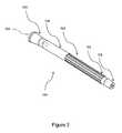
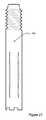
図1から図4を参照して本明細書に説明される実施形態は、遠位端104を有する本体102を有するインプラント100を含む。インプラント100は大腿骨の中への統合に適切である。これは、インプラント100が大腿骨との使用だけに適していることを示唆するわけではない。The embodiment described herein with reference to FIGS. 1-4includesan
1つの構成では、インプラント100はその生体適合性のために選ばれた鍛造チタンである。熟練した受取人は、例えばチタン合金、複合材料、又はそれ以外等、生体適合性である代替材料が使用できることを認識する。 In one configuration,
本体102は、骨格の骨の一部分を実質的に模倣するように構成されるので、本体102は細長い。本明細書に説明される実施形態では、インプラント100は、患者の大腿骨の部分的な置換物として患者の脚に植え込まれるように設計される。患者は、義肢を使用しようとし、インプラントが義肢の「付着」点として機能することを必要とする切断手術を受けた人である。 Since the
使用中、患者の肉の中へのインプラントの移行を妨げるように構成された、本体102に対して拡大される、口広げ加工を施された部分106を含む遠位端104。オッセオインテグレーションのインプラントは、空気に必ず曝されており、患者の肉及び皮膚を通過し、患者が、インプラントに対して上方への圧力をかけ、したがってインプラントの端部を患者の脚の肉の中に移行させることがある義肢を着用するときにゆっくりと『上方に押される』(つまり、上方に移行する)インプラントの『端部』の問題に悩まされている。対照的に、本明細書に説明される実施形態は、患者の脚の中へのインプラントの係る『上方への移行』を妨げるために口広げ加工を施された部分106を活用する。 In use, a
口広げ加工を施された部分106は、骨110の露呈された端部157に形成された凹部155の中に位置するような大きさ及び形状に作られる。この結果として、口広げ加工を施された部分106は、該口広げ加工を施された部分106が中に挿入される骨格の骨の外周よりも小さい外周を有する。凹部155は、口広げ加工を施された部分106の端部が骨110の端部と同一平面となるように形作られる。 The lip-opened
口広げ加工を施された部分106は、インプラント挿入後に骨110の端部と同一平面であるので、外科医はインプラントを取り囲む骨の外側に皮膚を縫合できる。口広げ加工を施された部分106は骨110の端部を越えて伸長しないので、細菌コロニーが成長するための部位は存在しない。これは、バクテリア活性に起因するインプラント部位の周りの組織の炎症、感染、及び破壊のリスクを大幅に削減する。 Since the flared
また、口広げ加工を施された部分106は、インプラント挿入後に骨110の端部と同一平面になるので、骨110を取り囲む軟組織はインプラントに付着しない。結果として、歩行又はそれ以外を通して等、インプラント100を通して伝えられた力は、インプラント100及び骨110を通って直接的に伝達され、人工臼蓋を通って又は軟組織を通ってのいずれでも消散されない。これがエネルギー損失を最小限に抑える。 In addition, since the
一実施形態では、口広げ加工を施された部分106の端部はナノ粒子で被覆される、又はインプラントを取り囲む軟組織間の摩擦、及び結果として生じる患者が感じる刺激を最小限に抑えるために高度に研磨される。 In one embodiment, the end of the mouth-opened
軟組織はインプラント100に付着しないので、インプラント106及び骨を取り囲む筋肉及び軟組織は自然に骨に付着するように促される。これが筋力低下を最小限に抑える又は排除し、患者が、そうでなければ失われるだろう歩行又はそれ以外の感覚相互作用を感じることを可能にする。 Because soft tissue does not adhere to the
口広げ加工を施された部分106は、口広げ加工を施された部分が本体部分102よりも幅広くなるように本体部分102に関して拡大される。この結果、口広げ加工を施された部分106は、本体部分102よりも大きい断面積を有する。 The
口広げ加工を施された部分106の少なくとも一部は、インプラント100が患者の脚の義足から突出する部位での感染又は免疫反応の可能性を削減するために生理学的に不活性な物質によって被覆される。本明細書に説明される実施形態では、生理学的に不活性な物質はニオブであるが、金又は既知の若しくは生理学的に不活性であることが発見される任意の他のコーティング等の他のコーティングが使用されてもよいことが理解される。係る変形形態は当業者の理解の範囲内である。 At least a portion of the mouth-opened
インプラント100の遠位端104は、(後により詳細に説明される)結合部品を受け入れるように構成される結合部品107をさらに含む。 The
コーティングを有する口広げ加工を施された部分106に加えて、本体102の少なくとも一部分は、インプラント100が(図4で110として示される)既存の骨格の骨の中に統合するのを支援する目的を有するコーティング(概して108によって示される)も有してよい。 In addition to the flared
一実施形態では、コーティングは、多孔質構造の中への骨の成長を促すのに役立ち、それによって既存の骨格の骨の中へのインプラントのオッセオインテグレーションを支援する適切な多孔質構造である。一実施形態では、多孔質構造は、プラズマ蒸着プロセスを使用することによって本体102の表面に付着されるチタンから形成される。 In one embodiment, the coating is a suitable porous structure that helps promote bone growth into the porous structure, thereby supporting osseointegration of the implant into the existing skeletal bone . In one embodiment, the porous structure is formed from titanium that is attached to the surface of the
インプラントは、人間の大腿骨の曲線を模倣するように構成される、領域112で概して可視である曲線状の形状を有する。異なるタイプのインプラントが、特定の生理学的な制約を満たすために必要とされることがあるように異なる形状及び外形を有してよいことが理解される。係る変形形態は当業者の理解の範囲内である。 The implant has a curvilinear shape that is generally visible in
インプラント100の本体102は、本体102の一部分に沿って伸長する少なくとも1つの突出部114をさらに含む。突出部は、インプラント100が骨格の骨の内側に位置するときにインプラント100の回転を妨げるために『把持』を提供することによって、使用中、骨格の骨に対するインプラントの回転を防ぐように構成される。図に示される実施形態では、突出部114は、インプラントの本体に沿って長手方向に伸長する少なくとも1つのスプラインである。ただし、同じ機能性を達成する他の変形形態が隆起パターン(『ジグザグ』パターン)、円周上の隆起、又は他の簡略なパターン若しくは複雑なパターンの提供を含んでよいことが理解される。 The
また、インプラント100は、患者が人工股関節インプラント(又は他のインプラント)も受け入れることができるようにするために先細である近位端部116も有する。 The
1つの構成では、少なくとも1つの突出部114が近位端116に隣接する部位に位置する。生物学的接着のための多孔質部分108は遠位端104に隣接して位置する。 In one configuration, at least one
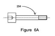
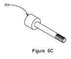
ここで図5A〜図5C及び図6A〜図6Cを参照すると、人工装具(不図示)に接続する対応する結合部分254を受け入れるように構成されたねじ部252を含む第1の結合部品250が示される。 Referring now to FIGS. 5A-5C and 6A-6C, a
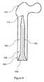
図7から図11を参照して本明細書に説明される第2の実施形態では、少なくとも1つの端部204を有する本体202を含むインプラント200。本体202は骨格の骨の一部分を実質的に模倣するように構成されるので、本体202は細長く、本明細書に説明される例の実施形態では、インプラントは人間の患者の脛骨の少なくとも一部分を模倣するように構成される。これは、インプラント200が脛骨との使用のためだけに適切であることを示唆するわけではない。 In a second embodiment described herein with reference to FIGS. 7-11, an
インプラント200は、3次元印刷によって又は熟練した受取人によって理解される他の手段によって形成することができ、生体適合性材料から作られる。 The
インプラント200は脛骨の一部分を模倣するように構成されるので、インプラント200は、脛骨の断面外形に合うために概して三角形の断面外形を有する。熟練した受取人はその変形形態を認識するだろう。 Since the
使用中、患者の骨の中へのインプラントの移行を妨げるように構成された口広げ加工を施された部分206を含む遠位端204。オッセオインテグレーションのインプラントは、空気に必ず曝されており、患者の肉及び皮膚を通過し、患者が、インプラントに対して上方への圧力をかけ、したがってインプラントの端部を患者の脚の骨の中に移行させることがある義肢を着用するときにゆっくりと『上方に押される』(つまり、上方に移行する)インプラントの『端部』の問題に悩まされている。対照的に、本明細書に説明される実施形態は、骨に対する上方への圧力を拡散し、それによって患者の脚の中へのインプラントの係る『上方への移行』を妨げるために口広げ加工を施された部分206を活用する。 In use, a
インプラントの口広げ加工を施された部分206が実質的に三角形の断面(つまり、図示される実施形態では、図11に示されるように丸みを付けた角によって接続される3つの実質的にまっすぐな壁)を有することも理解されるだろう。ただし、本体202が実質的に丸い(円形の)断面を有することが留意される。つまり、インプラント200は、遠位端204で実質的に三角形であることから本体202で実質的に丸いことへ近づく。 The flared portion 206 of the implant has a substantially triangular cross-section (ie, in the illustrated embodiment, three substantially straight surfaces connected by rounded corners as shown in FIG. 11) It will be understood that it has a wall. However, it is noted that the
本体202の少なくとも一部は、本体202の患者の骨の中へのオッセオインテグレーションを支援する粗いコーティング208で被覆される。一実施形態では、コーティングは、多孔質構造への骨の成長を促し、それによって骨格の骨の中へのインプラントのオッセオインテグレーションを支援する適切な多孔質構造である。一実施形態では、多孔質構造は、プラズマ蒸着プロセスを使用することによって本体202の表面に付着されるチタンから形成される。 At least a portion of the
口広げ加工を施された部分206は、骨の露呈された端部に形成された凹部の中に位置するような大きさ及び形状に作られる。この結果として、口広げ加工を施された部分206は、該口広げ加工を施された部分206が中に挿入される骨格の骨の外周よりも小さい外周を有する。凹部は、口広げ加工を施された部分206の端部が骨の端部と同一平面となるように形作られる。 The flared portion 206 is sized and shaped to lie in a recess formed in the exposed end of the bone. As a result, the flared portion 206 has an outer periphery that is smaller than the outer periphery of the bone of the skeleton into which the flared portion 206 is inserted. The recess is shaped so that the end of the flared portion 206 is flush with the end of the bone.
口広げ加工を施された部分206は、インプラント挿入後に骨の端部と同一平面であるので、外科医はインプラントを取り囲む骨の外側に皮膚を縫合できる。口広げ加工を施された部分106は骨の端部を越えて伸長しないので、細菌コロニーが成長するための部位は存在しない。これは、バクテリア活性に起因するインプラント部位の周りの組織の炎症、感染、及び破壊のリスクを大幅に削減する。 The flared portion 206 is flush with the end of the bone after insertion of the implant so that the surgeon can suture the skin outside the bone surrounding the implant. Because the mouth-opened
また、口広げ加工を施された部分206は、インプラント挿入後に骨の端部と同一平面になるので、骨を取り囲む軟組織はインプラントに付着しない。結果として、歩行又はそれ以外を通して等、インプラント200を通して伝えられた力は、インプラント200及び骨を通って直接的に伝達され、人工臼蓋を通って又は軟組織を通ってのいずれでも消散されない。これがエネルギー損失を最小限に抑える。 In addition, since the portion 206 subjected to the spreading process is flush with the end of the bone after the insertion of the implant, the soft tissue surrounding the bone does not adhere to the implant. As a result, forces transmitted through the
口広げ加工を施された部分206の端部はナノ粒子で被覆される、又はインプラントを取り囲む軟組織間の摩擦、及び結果として生じる患者が感じる刺激を最小限に抑えるために高度に研磨される。 The end of the mouth-opened portion 206 is coated with nanoparticles or highly polished to minimize friction between the soft tissue surrounding the implant and the resulting irritation the patient feels.
軟組織はインプラント200に付着しないので、インプラント206及び骨を取り囲む筋肉及び軟組織は自然に骨に付着するように促される。これが筋力低下を最小限に抑える又は排除し、患者が、そうでなければ失われるだろう歩行又はそれ以外の感覚相互作用を感じることを可能にする。 Because soft tissue does not adhere to the
口広げ加工を施された部分206は、口広げ加工を施された部分が本体部分202よりも幅広くなるように本体部分202に関して拡大される。この結果、口広げ加工を施された部分106は、本体部分202よりも大きい断面積を有する。 The part 206 subjected to the flaring process is enlarged with respect to the
インプラント200の遠位端204は、結合部分を受け入れるように構成される結合部品208をさらに含む。 The
インプラント200の本体202は、本体202の一部分に沿って伸長する遠位端204に隣接する少なくとも1つの突出部212をさらに含む。突出部は、インプラント200が骨格の骨の内側に位置するときにインプラント200の回転を妨げるために『把持』を提供することによって、使用中、骨格の骨に対するインプラントの回転を防ぐように構成される。図に示される実施形態では、突出部214は、インプラントの本体に沿って長手方向に伸長する少なくとも1つのスプラインである。ただし、同じ機能性を達成する他の変形形態が隆起パターン(『ジグザグ』パターン)、円周上の隆起、又は他の簡略なパターン若しくは複雑なパターンの提供を含んでよいことが理解される。 The
インプラントは、実施形態では『ねじ穴』として説明される少なくとも1つの固定点214をさらに含み、ねじ穴は、適切なねじ又は他の固定装置を使用することによって脛骨にインプラントを固定できるようにするための1つ又は複数の固定点を提供するように構成される。 The implant further includes at least one
1つの構成では、本体202は中心ボア299を含む。ねじは中心ボアを通って固定点214に配置され、次いで、インプラント200が定位置にあるときに取り囲む骨の中にねじ込むことができる。 In one configuration, the
固定点214がねじ込みブッシュの形をとってよいことが理解される。固定点214がねじ込みブッシュである場合、ねじは、骨の中にインプラント200を挿入する前に固定点214を通して部分的に挿入できる。インプラント200が骨の中に挿入されると、部分的に挿入されたねじは中心ボアを通って完全にねじ込まれ、骨と係合できる。 It is understood that the
代替実施形態では、固定点214の位置を決めるために骨の外側の上に治具を配置することができ、ねじは骨の外側から固定点214を通って挿入できる。 In an alternative embodiment, a jig can be placed on the outside of the bone to position the
また、インプラント200は、第2の付着点を含む近位端216も有する。
図1〜図6Cのインプラントは、固定点214のそれらに類似した1つ又は複数の固定点を含んでよい。 The implant of FIGS. 1-6C may include one or more fixation points similar to those of fixation points 214.
図12から図14を参照して本明細書に説明される第3の実施形態では、少なくとも1つの端部304を有する本体302を含むインプラント300。本体302は骨格の骨の一部分を実質的に模倣するように構成されるので、本体302は細長い。本明細書に説明される実施形態では、インプラント300は、患者の大腿骨の部分的な置換物として患者の脚に植え込まれるように設計される。患者は義肢を使用しようとし、インプラントが義肢の「付着」点として機能することを必要とする切断手術を受けた人である。 In a third embodiment described herein with reference to FIGS. 12-14, an
使用中、患者の骨の中へのインプラントの移行を妨げるように構成された段付きの部分306を含む少なくとも1つの端部304。オッセオインテグレーションのインプラントは、空気に必ず曝されており、患者の肉及び皮膚を通過し、患者が、インプラントに対して上方への圧力をかけ、したがってインプラントの端部を患者の脚の骨の中に移行させることがある義肢を着用するときにゆっくりと『上方に押される』(つまり、上方に移行する)インプラントの『端部』の問題に悩まされている。対照的に、本明細書に説明される実施形態は、患者の脚の中へのインプラントの係る『上方への移行』を妨げるために段付き部分306を活用する。 At least one end 304 including a stepped portion 306 configured to prevent migration of the implant into the patient's bone in use. The osseointegration implant is always exposed to air, passes through the patient's flesh and skin, and the patient exerts an upward pressure on the implant, thus the end of the implant on the patient's leg bone It suffers from the problem of the “end” of the implant being slowly “pushed” (ie, moving upward) when wearing a prosthetic limb that may be moved in. In contrast, the embodiments described herein utilize a stepped portion 306 to prevent such “upward transition” of the implant into the patient's leg.
段付き部分306の少なくとも一部は、インプラント300が患者の脚の肉に接触する部位での感染又は免疫反応の可能性を削減するために、生理学的に不活性な物質で被覆される。本明細書に説明される実施形態では、生理学的に不活性な物質はニオブであるが、金又は既知の若しくは生理学的に不活性であることが発見される任意の他のコーティング等の他のコーティングが使用されてもよいことが理解される。係る変形形態は当業者の理解の範囲内である。 At least a portion of the stepped portion 306 is coated with a physiologically inert material to reduce the likelihood of infection or an immune response at the site where the
インプラント300の少なくとも1つの端部304は、(後により詳細に説明される)結合部分を受け入れるように構成される結合部品307をさらに含む。 At least one end 304 of the
コーティングを有する段付き部分306に加えて、本体302の少なくとも一部分は、インプラント300が(図14で310として示される)骨格の骨の中に統合するのを支援する目的を有するコーティング(概して308によって示される)も有してよい。 In addition to the stepped portion 306 having a coating, at least a portion of the body 302 has a coating (generally by 308) that has the purpose of assisting the
一実施形態では、コーティングは、多孔質構造の中への骨の成長を促すのに役立ち、それによって既存の骨格の骨の中へのインプラントのオッセオインテグレーションを支援する適切な多孔質構造である。一実施形態では、多孔質構造は、プラズマ蒸着プロセスを使用することによって本体302の表面に付着されるチタンから形成される。 In one embodiment, the coating is a suitable porous structure that helps promote bone growth into the porous structure, thereby supporting osseointegration of the implant into the existing skeletal bone . In one embodiment, the porous structure is formed from titanium that is attached to the surface of the body 302 by using a plasma deposition process.
インプラントは、人間の大腿骨の曲線を模倣するように構成される、領域312で概して可視である曲線状の形状を有する。異なるタイプのインプラントが、特定の骨格の及び解剖学上の制約を満たすために必要とされることがあるように異なる形状及び外形を有してよいことが理解される。係る変形形態は当業者の理解の範囲内である。 The implant has a curvilinear shape that is generally visible in area 312 that is configured to mimic the curve of a human femur. It is understood that different types of implants may have different shapes and profiles as may be required to meet specific skeletal and anatomical constraints. Such variations are within the purview of those skilled in the art.
インプラント300の本体302は、本体302の一部分に沿って伸長する少なくとも1つの突出部314をさらに含む。突出部は、インプラント300が骨格の骨の内側に位置するときにインプラント300の回転を妨げるための『把持』を提供することによって、使用中、骨格の骨に対するインプラントの回転を防ぐように構成される。図に示される実施形態では、突出部314は、インプラントの本体に沿って長手方向に伸長する少なくとも1つのスプラインである。ただし、同じ機能性を達成する他の変形形態が隆起パターン(『ジグザグ』パターン)、円周上の隆起、又は他の簡略なパターン若しくは複雑なパターンの提供を含んでよいことが理解される。 The body 302 of the
また、インプラント300は、患者が、脚のインプラントに付着できる人工股関節インプラント(又は他のインプラント)も受け入れることができるようにするために、先細である近位端部316も有する。 The
ここで図15A〜図15Bを参照すると、インプラント300と協調するように構成される結合部品が示される。結合部品400は、インプラント300に係止して嵌るように構成された係止長穴402を含む。また、結合部品は、結合部品400にプロテーゼ(不図示)を係止するためのピン(不図示)を受け入れるように構成される係止ピン溝406と協調して直接的又は間接的のどちらかで人工装具(不図示)と接続するように構成されたコネクタ係合ボス404も含む。 Referring now to FIGS. 15A-15B, a coupling component configured to cooperate with the
ここで図16、図17、及び図18を参照すると、オッセオインテグレーションのインプラント200が脛骨のベースプレート290に付着可能である本発明の第4の実施形態が示される。脛骨のベースプレート290は、膝の置換物で使用される。オッセオインテグレーションのインプラント200の近位端216は先細であり、脛骨のベースプレート290に突起部292を受け入れるように構成された受け入れ凹部291を含む。突起部292が受け入れ凹部291に受け入れられると、2つはねじ、ボルト、又は熟練した受取人によって理解されるだろう他の固定手段を使用することによって固定点293及び294でともに固定できる。図18は、オッセオインテグレーションインプラント200に対する伸長部280である。 Referring now to FIGS. 16, 17, and 18, a fourth embodiment of the present invention is shown in which an
図16、図17、及び図18は膝関節置換術及び脛骨のオッセオインテグレーションのインプラントに関して説明されてきたが、熟練した受取人は、これが、ベースプレートが使用される他の関節置換術に適用されるだろうことを認識する。 While Figures 16, 17 and 18 have been described with regard to knee replacement and tibial osseointegration implants, skilled recipients may apply to other joint replacements where a base plate is used. Recognize that it will
ここで図19を参照すると、図示されない上腕骨のオッセオインテグレーションのインプラントが上腕頭置換物502に付着可能である本発明の第5の実施形態が示される。上腕骨のオッセオインテグレーションインプラントは、上述されたオッセオインテグレーションのインプラント100の特徴を含む。上腕骨のオッセオインテグレーションのインプラントは、近位端516が受け入れ凹部591を含むのを除き、伸長部500を含む。上腕頭置換物502は、伸長部500の受け入れ凹部591の中に挿入されるように構成された突起部592を含む。突起部592が受け入れ凹部591に受け入れられると、2つはねじ、ボルト、又は熟練した受取人によって理解されるだろう他の固定手段を使用することによって固定点593及び594でともに固定できる。 Referring now to FIG. 19, a fifth embodiment of the present invention is shown in which a humeral osseointegration implant, not shown, can be attached to the
ここで図20を参照すると、股関節置換物602が、大腿骨で使用されるときにオッセオインテグレーションのインプラント100に付着可能となるように構成される本発明の第6の実施形態が示される。股関節置換物602は、オッセオインテグレーションのインプラント100の近位端116を受け入れるように構成された凹部692を含む。近位端116が凹部691に受け入れられると、2つはねじ、ボルト、又は熟練した受取人によって理解されるだろう他の固定手段を使用することによってともに固定できる。 Referring now to FIG. 20, a sixth embodiment of the present invention is shown wherein a hip replacement 602 is configured to be able to attach to the
図21は、本体ねじ伸長部分702を示す。図22は、伸長部分702を受け入れる凹部701を含む本体部700を示す。伸長部分702は、オッセオインテグレーションのインプラント100、200にとってのアンカーとして作用する、骨格の骨へねじ止めするように本体部を通して通過する。FIG. 21 shows the
図23は、固定点814を有する、オッセオインテグレーションのインプラント100のものに類似したオッセオインテグレーションのインプラント800を有する本発明の第7の実施形態を示す。固定点814は固定点214と同様に動作するが、遠位端よりむしろ近位端に位置する。 FIG. 23 shows a seventh embodiment of the invention having an
図24は、固定点914を有する、オッセオインテグレーションのインプラント200のものに類似したオッセオインテグレーションのインプラント900を有する本発明の第8の実施形態を示す。固定点914は固定点214と同様に動作するが、遠位端よりむしろ近位端に位置し、受け入れ部分916は輪郭を描かれた凹部である。 FIG. 24 shows an eighth embodiment of the invention having an
言うまでもなく、オッセオインテグレーションのインプラントは異なるサイズで製造されてよく、これにより正しいサイズが異なる身長、体重、及び体格の異なる患者に提供され得ることが理解される。これは、異なる長さのインプラント及び/又は異なる半径方向の外形を有するインプラントを製造することを含んでよい。係る変形形態は、本明細書に説明され、定義されるより幅広い発明の概念によって包含される。
優位点及び産業上の利用It will be appreciated that osseointegration implants may be manufactured in different sizes, so that the correct size can be provided to patients of different height, weight, and body size. This may include producing implants of different lengths and / or implants having different radial profiles. Such variations are encompassed by the broader inventive concepts described and defined herein.
Advantages and industrial use
本明細書に説明された実施形態及びより幅広い発明の優位点の1つは、本発明が、患者の肉の中へのインプラントの上方への移行を停止するために遠位端を口広げ加工した点である。 One of the advantages of the embodiments described herein and of the broader invention that the present invention is to open out the distal end to stop the upward migration of the implant into the patient's meat It is the point that
さらに、本明細書に説明される実施形態は、インプラントの回転を妨げる長手方向のスプラインを提供する。 Further, the embodiments described herein provide a longitudinal spline that prevents rotation of the implant.
また、インプラントは好ましくは、オッセオインテグレーションを誘発し、支援するために働くプラズマチタンスプレイ等の多孔質コーティングも含む。 The implant also preferably includes a porous coating, such as a plasma titanium spray, which serves to induce and support osseointegration.
最後に、実施形態は、患者によって必要とされることがある将来の股関節/首のインプラントを可能にするために近位端で先細である。
免責条項Finally, embodiments are tapered at the proximal end to allow for future hip / neck implants that may be needed by the patient.
Disclaimer
本明細書を通して、文脈上他の意味に解釈すべき場合を除いて、単語「含む」又は「含む」又は「含んだ」等の変形は、述べられている整数又は整数のグループの包含を暗示するが、他のいかなる整数又は整数のグループを除外するものではないことが理解される。 Throughout the specification, except where the context is to be interpreted in another sense, variants such as the words "include" or "include" or "include" imply the inclusion of the stated integer or group of integers However, it is understood that it does not exclude any other integer or group of integers.
当業者は、本明細書に説明される本発明が明確に説明された変形形態及び変更形態以外の変形形態及び変更形態の影響を受けやすいことを理解する。本発明は係るすべての変形形態及び変更形態を含む。また、本発明は個別に又は集合的に明細書に参照された又は示された特徴のすべて、及びステップ又は特徴のすべての組合せ又は任意の2つ以上も含む。 Those skilled in the art will appreciate that the invention described herein is susceptible to variations and modifications other than those explicitly described. The present invention includes all such variations and modifications. In addition, the present invention also includes all of the features individually or collectively referred to or indicated in the specification, and all combinations or arbitrary two or more of the steps or features.
本明細書に使用される選択された用語の他の定義は、本発明の詳細な説明の中で見つけられ、全体で適用してよい。特別の定めのない限り、本明細書に使用されるすべての他の科学用語、医学用語、工学用語、及び技術用語は、本発明が属する技術の当業者に一般に理解されるのと同じ意味を有する。 Other definitions of selected terms used herein may be found in the detailed description of the invention and apply throughout. Unless otherwise stated, all other scientific, medical, engineering and technical terms used herein have the same meaning as commonly understood by one of ordinary skill in the art to which this invention belongs. Have.
Claims (26)
Translated fromJapanese本体および少なくとも1つの端部であって、前記本体が、骨の中に形成された経路内に静置し、かつ骨格の骨の一部分を実質的に形成するように構成されている本体および少なくとも1つの端部
を備え、
前記少なくとも1つの端部が、使用中、患者の前記骨格の骨の中への前記インプラントの移行を妨げるように構成された拡大部分を含み、
前記拡大部分が、前記骨格の骨の端に形成された凹部の中に静置するように構成されており、
前記凹部が、前記経路に連結しており、よりおおきな前記経路の直径を有し、
前記拡大部分を含む少なくとも1つの端部が、前記端部が前記骨格の骨の端と同一平面にあるように構成されている、
インプラント。An implant configured for integration into a bone of a patient's skeleton,
A body and at least one end, wherein the body is configured to rest within a path formed in the bone and to substantiallyform a portion of the bone of the skeleton; and at least With one end,
The at least one end includes an enlarged portion configured to prevent transfer of the implant into the bone of the patient's skeleton during use;
The enlargement is configured to rest in a recess formed in an end of a bone of the skeleton;
The recess is connected to the path and has a larger diameter of the path;
At least one end including the enlarged portion is configured such that the end is flush with an end of a bone of the skeleton;
Implant.
本体および少なくとも1つの端部であって、前記本体が、前記骨の中に形成された経路内に静置し、かつ骨格の骨の一部を実質的に形成するように構成されている、本体および少なくとも1つの端部
を含み、
前記少なくとも1つの端部が、使用中、前記患者への前記インプラントの移行を妨げるように構成されており、
前記本体が、前記骨格の骨に前記本体を固定するように構成されたロック手段を受け入れるように構成された拡大部分に遠位の開口部を含む、
インプラント。An implant configured to integrate into the bones of a patient's skeleton,
A body and at least one end, wherein the body is configured to rest within a path formed in the bone and substantiallyform a portion of a skeletal bone; Including a body and at least one end;
The at least one end is configured to prevent migration of the implant to the patient during use;
Wherein the body includes a distal opening in theconfigured expansion most to receive a locking means which is configured to secure the body to bone of the skeleton,
Implant.
Applications Claiming Priority (7)
| Application Number | Priority Date | Filing Date | Title |
|---|---|---|---|
| AU2014901404 | 2014-04-16 | ||
| AU2014901404AAU2014901404A0 (en) | 2014-04-16 | An osseointegrable device | |
| AU2014901958AAU2014901958A0 (en) | 2014-05-23 | An osseointegrable device | |
| AU2014901958 | 2014-05-23 | ||
| AU2014902373 | 2014-06-20 | ||
| AU2014902373AAU2014902373A0 (en) | 2014-06-20 | An implantable device | |
| PCT/AU2015/000234WO2015157809A1 (en) | 2014-04-16 | 2015-04-16 | An osseointegrable device |
Publications (2)
| Publication Number | Publication Date |
|---|---|
| JP2017511746A JP2017511746A (en) | 2017-04-27 |
| JP6554166B2true JP6554166B2 (en) | 2019-07-31 |
Family
ID=54323271
Family Applications (1)
| Application Number | Title | Priority Date | Filing Date |
|---|---|---|---|
| JP2017505686AActiveJP6554166B2 (en) | 2014-04-16 | 2015-04-16 | Osseo Integration-capable device |
Country Status (15)
| Country | Link |
|---|---|
| US (1) | US10456178B2 (en) |
| EP (2) | EP3131506B1 (en) |
| JP (1) | JP6554166B2 (en) |
| KR (1) | KR102412682B1 (en) |
| CN (1) | CN106456342B (en) |
| AU (1) | AU2015246643C1 (en) |
| CA (1) | CA2945830C (en) |
| DK (1) | DK3131506T3 (en) |
| ES (2) | ES2869075T3 (en) |
| IL (1) | IL248443B (en) |
| MY (1) | MY185691A (en) |
| NZ (1) | NZ721835A (en) |
| PL (1) | PL3131506T3 (en) |
| SG (1) | SG11201608621QA (en) |
| WO (1) | WO2015157809A1 (en) |
Families Citing this family (9)
| Publication number | Priority date | Publication date | Assignee | Title |
|---|---|---|---|---|
| US10925755B2 (en)* | 2016-08-17 | 2021-02-23 | Arizona Board Of Regents On Behalf Of Arizona State University | Osseointegratable prosthetic device and manufacturing method |
| EP3621537B1 (en)* | 2017-05-09 | 2025-01-08 | University of Utah Research Foundation | Osseointegrated implant assembly having transverse through-openings |
| CN107638237A (en)* | 2017-10-27 | 2018-01-30 | 吉林大学 | Implantable Prosthetic Connection Device |
| JP7566632B2 (en)* | 2018-03-30 | 2024-10-15 | デピュイ・シンセス・プロダクツ・インコーポレイテッド | Surface texture and method of fabrication of three-dimensional porous structures for bone ingrowth - Patents.com |
| KR102287458B1 (en) | 2019-10-11 | 2021-08-09 | 국립암센터 | Amputation osseous implant with mesh flange for direct prosthesis limb attachment |
| TR202017292A1 (en)* | 2020-10-30 | 2022-05-23 | Tst Rakor Ve Tibbi Aletler Sanayi Ve Ticaret Ltd Sirketi | ARTRODESIA NAIL |
| EP4193969A1 (en)* | 2021-12-10 | 2023-06-14 | Arthemidex S.r.l. | System of intra-bone prosthesis for amputation |
| DE102023130257A1 (en)* | 2023-11-02 | 2025-05-08 | Helena Streilau | Endo-Exo prosthesis for limbs |
| US20250302645A1 (en)* | 2024-03-29 | 2025-10-02 | Mark Pitkin | Powered prosthetic foot with bi-directional neural intuitive control and sensation including an improved control system with sensorimotor feedback and closed-loop operation with multifaceted input/output |
Family Cites Families (24)
| Publication number | Priority date | Publication date | Assignee | Title |
|---|---|---|---|---|
| US4158895A (en)* | 1978-02-09 | 1979-06-26 | Nasa | Prosthesis coupling |
| US4976258A (en)* | 1983-03-09 | 1990-12-11 | Howmedica International, Inc. | Locking nail |
| DE3439993C2 (en) | 1984-11-02 | 1986-12-04 | Friedrichsfeld GmbH Keramik- und Kunststoffwerke, 6800 Mannheim | Implant for supplying amputation stumps |
| DE3439931A1 (en)* | 1984-11-02 | 1986-05-15 | Robert 5223 Nümbrecht Heister | Screened plug connector (II) |
| US5169597A (en)* | 1989-12-21 | 1992-12-08 | Davidson James A | Biocompatible low modulus titanium alloy for medical implants |
| DE19705571A1 (en)* | 1997-02-14 | 1998-09-03 | Ralf Dr Schroeder | Expanding dental implant for jaw |
| JP2001512348A (en)* | 1997-02-25 | 2001-08-21 | ノーベル バイオケア アクティエボラーグ | Bone fixation element |
| GB0015479D0 (en) | 2000-06-23 | 2000-08-16 | Univ London | Transcutaneous Prosthesis |
| SE522803C2 (en)* | 2002-12-19 | 2004-03-09 | Exopro L A | Fixture for anchoring prosthesis in bone tissue has anchoring part and application part which connects to prosthesis, application part having outer end and end connected with anchoring part |
| US7534271B2 (en)* | 2004-01-22 | 2009-05-19 | Smith + Nephew | Femoral hip prosthesis and method of implantation |
| WO2007081876A2 (en)* | 2006-01-04 | 2007-07-19 | Liquidia Technologies, Inc. | Nanostructured surfaces for biomedical/biomaterial applications and processes thereof |
| US7909883B2 (en)* | 2007-02-21 | 2011-03-22 | Sidebotham Christopher G | Percutaneous implant for limb salvage |
| US8177849B2 (en)* | 2007-05-07 | 2012-05-15 | Zimmer, Inc. | Methods and apparatuses for attaching tissue to orthopaedic implants |
| US9814583B2 (en)* | 2007-05-08 | 2017-11-14 | Zimmer, Inc. | Modular stem extension |
| US8366783B2 (en)* | 2007-08-27 | 2013-02-05 | Samuelson Kent M | Systems and methods for providing deeper knee flexion capabilities for knee prosthesis patients |
| FR2940760B1 (en)* | 2009-01-08 | 2010-12-31 | Memometal Technologies | ORTHOPEDIC IMPLANT FOR DIGITAL ARTHROPLASTY |
| DE102009027255B4 (en)* | 2009-02-06 | 2012-08-23 | Hannu Grundei | Subcutaneous implant for intramedullary use in a long bone to couple an exoprosthetic standard part |
| GB0905009D0 (en)* | 2009-03-24 | 2009-05-06 | Stanmore Implants Worldwide Ltd | Percutaneous device |
| US9433505B2 (en) | 2011-06-06 | 2016-09-06 | University Of Utah Research Foundation | Percutaneous osseointegrated implant assembly for use in supporting an exo-prosthesis |
| AU2012316698B2 (en)* | 2011-06-06 | 2015-03-26 | University Of Utah Research Foundation | Percutaneous osseointegrated prosthetic implant system |
| WO2014040061A1 (en) | 2012-09-10 | 2014-03-13 | Ortho Transmission, Llc | Transcutaneous implant for skeletal attachment of external prosthetic devices |
| DK2911506T3 (en) | 2012-10-24 | 2017-11-13 | Clariant Int Ltd | Operationally reducing compositions |
| DE102012021003B4 (en) | 2012-10-26 | 2015-02-12 | Otto Bock Healthcare Products Gmbh | Percutaneous implant and method of making such an implant |
| GB2507327A (en) | 2012-10-26 | 2014-04-30 | Fitzbionics Ltd | Percutaneous implant for attaching exoprosthesis |
- 2015
- 2015-04-16PLPL15780745Tpatent/PL3131506T3/enunknown
- 2015-04-16CACA2945830Apatent/CA2945830C/enactiveActive
- 2015-04-16JPJP2017505686Apatent/JP6554166B2/enactiveActive
- 2015-04-16USUS15/110,608patent/US10456178B2/enactiveActive
- 2015-04-16KRKR1020167031901Apatent/KR102412682B1/enactiveActive
- 2015-04-16NZNZ721835Apatent/NZ721835A/enunknown
- 2015-04-16SGSG11201608621QApatent/SG11201608621QA/enunknown
- 2015-04-16MYMYPI2016001853Apatent/MY185691A/enunknown
- 2015-04-16ESES15780745Tpatent/ES2869075T3/enactiveActive
- 2015-04-16EPEP15780745.4Apatent/EP3131506B1/enactiveActive
- 2015-04-16ESES20171411Tpatent/ES3014386T3/enactiveActive
- 2015-04-16WOPCT/AU2015/000234patent/WO2015157809A1/enactiveApplication Filing
- 2015-04-16EPEP20171411.0Apatent/EP3701914B1/enactiveActive
- 2015-04-16DKDK15780745.4Tpatent/DK3131506T3/enactive
- 2015-04-16CNCN201580029853.0Apatent/CN106456342B/enactiveActive
- 2015-04-16AUAU2015246643Apatent/AU2015246643C1/enactiveActive
- 2016
- 2016-10-20ILIL248443Apatent/IL248443B/enunknown
Also Published As
| Publication number | Publication date |
|---|---|
| CN106456342A (en) | 2017-02-22 |
| ES2869075T3 (en) | 2021-10-22 |
| DK3131506T3 (en) | 2021-05-17 |
| AU2015246643A1 (en) | 2016-07-21 |
| EP3131506B1 (en) | 2021-03-17 |
| AU2015246643C1 (en) | 2022-01-27 |
| ES3014386T3 (en) | 2025-04-22 |
| KR20170020747A (en) | 2017-02-24 |
| EP3701914C0 (en) | 2024-12-04 |
| MY185691A (en) | 2021-05-30 |
| EP3701914A1 (en) | 2020-09-02 |
| WO2015157809A1 (en) | 2015-10-22 |
| EP3131506A4 (en) | 2017-10-04 |
| EP3701914B1 (en) | 2024-12-04 |
| IL248443A0 (en) | 2016-12-29 |
| JP2017511746A (en) | 2017-04-27 |
| AU2015246643B2 (en) | 2020-05-21 |
| CA2945830A1 (en) | 2015-10-22 |
| SG11201608621QA (en) | 2016-11-29 |
| EP3131506A1 (en) | 2017-02-22 |
| CA2945830C (en) | 2022-08-09 |
| CN106456342B (en) | 2019-11-08 |
| US10456178B2 (en) | 2019-10-29 |
| US20160331422A1 (en) | 2016-11-17 |
| PL3131506T3 (en) | 2021-08-23 |
| NZ721835A (en) | 2020-05-29 |
| KR102412682B1 (en) | 2022-06-23 |
| IL248443B (en) | 2022-06-01 |
Similar Documents
| Publication | Publication Date | Title |
|---|---|---|
| JP6554166B2 (en) | Osseo Integration-capable device | |
| Thesleff et al. | Biomechanical characterisation of bone-anchored implant systems for amputation limb prostheses: a systematic review | |
| US20240268965A1 (en) | Prosthesis Surface Treatment for Soft Tissue Attachment Thereto | |
| US7909883B2 (en) | Percutaneous implant for limb salvage | |
| JP6469589B2 (en) | Implant for lower limb amputation | |
| US10925737B2 (en) | Mandible endoprosthesis implant, implant system, surgical kit, and methods for surgically repairing a mandible | |
| JP6506039B2 (en) | Transdermal osseointegrated implant assembly for use in supporting extracorporeal prostheses | |
| JP2008531146A (en) | Set that constitutes a surface reconstruction hip implant | |
| WO2009105535A1 (en) | Transcutaneous osseointegrated device for prostheses | |
| CN103705316A (en) | Orthopaedic hip prosthesis having femoral stem components with varying a/p taper angles | |
| US20050267586A1 (en) | Canine femoral stem system | |
| CN210019806U (en) | Artificial joint casting | |
| US20240033093A1 (en) | Prostheses with flexible surface lamellas | |
| US20240148509A1 (en) | Connector for osseointegration prosthesis and implant system | |
| Abbas et al. | Lower Limb Amputation Prosthetic Osseointegration Implant Systems | |
| US20240252217A1 (en) | Kit for the installation of prosthetic components and/or biomedical implants | |
| JP2003505147A (en) | Dislocation prevention biprosthetic leg | |
| JPH04226648A (en) | In vivo implanted prosthesis | |
| CN107427369B (en) | Temporary joint prosthese | |
| FAOUSSI et al. | Study of Different Orthopedic Implant for the Femoral Amputees |
Legal Events
| Date | Code | Title | Description |
|---|---|---|---|
| A521 | Request for written amendment filed | Free format text:JAPANESE INTERMEDIATE CODE: A523 Effective date:20170126 | |
| A621 | Written request for application examination | Free format text:JAPANESE INTERMEDIATE CODE: A621 Effective date:20180124 | |
| A131 | Notification of reasons for refusal | Free format text:JAPANESE INTERMEDIATE CODE: A131 Effective date:20181030 | |
| A977 | Report on retrieval | Free format text:JAPANESE INTERMEDIATE CODE: A971007 Effective date:20181031 | |
| A521 | Request for written amendment filed | Free format text:JAPANESE INTERMEDIATE CODE: A523 Effective date:20190128 | |
| TRDD | Decision of grant or rejection written | ||
| A01 | Written decision to grant a patent or to grant a registration (utility model) | Free format text:JAPANESE INTERMEDIATE CODE: A01 Effective date:20190702 | |
| A61 | First payment of annual fees (during grant procedure) | Free format text:JAPANESE INTERMEDIATE CODE: A61 Effective date:20190705 | |
| R150 | Certificate of patent or registration of utility model | Ref document number:6554166 Country of ref document:JP Free format text:JAPANESE INTERMEDIATE CODE: R150 | |
| R250 | Receipt of annual fees | Free format text:JAPANESE INTERMEDIATE CODE: R250 | |
| R250 | Receipt of annual fees | Free format text:JAPANESE INTERMEDIATE CODE: R250 | |
| R250 | Receipt of annual fees | Free format text:JAPANESE INTERMEDIATE CODE: R250 | |
| R250 | Receipt of annual fees | Free format text:JAPANESE INTERMEDIATE CODE: R250 |