JP6554045B2 - Dust collector and substrate processing system - Google Patents
Dust collector and substrate processing systemDownload PDFInfo
- Publication number
- JP6554045B2 JP6554045B2JP2016034316AJP2016034316AJP6554045B2JP 6554045 B2JP6554045 B2JP 6554045B2JP 2016034316 AJP2016034316 AJP 2016034316AJP 2016034316 AJP2016034316 AJP 2016034316AJP 6554045 B2JP6554045 B2JP 6554045B2
- Authority
- JP
- Japan
- Prior art keywords
- particles
- fluid
- node
- wall surface
- nodes
- Prior art date
- Legal status (The legal status is an assumption and is not a legal conclusion. Google has not performed a legal analysis and makes no representation as to the accuracy of the status listed.)
- Active
Links
Images


Classifications
- H—ELECTRICITY
- H01—ELECTRIC ELEMENTS
- H01L—SEMICONDUCTOR DEVICES NOT COVERED BY CLASS H10
- H01L21/00—Processes or apparatus adapted for the manufacture or treatment of semiconductor or solid state devices or of parts thereof
- H01L21/02—Manufacture or treatment of semiconductor devices or of parts thereof
- H01L21/02041—Cleaning
- H01L21/02057—Cleaning during device manufacture
- B—PERFORMING OPERATIONS; TRANSPORTING
- B01—PHYSICAL OR CHEMICAL PROCESSES OR APPARATUS IN GENERAL
- B01D—SEPARATION
- B01D43/00—Separating particles from liquids, or liquids from solids, otherwise than by sedimentation or filtration
- B—PERFORMING OPERATIONS; TRANSPORTING
- B01—PHYSICAL OR CHEMICAL PROCESSES OR APPARATUS IN GENERAL
- B01D—SEPARATION
- B01D21/00—Separation of suspended solid particles from liquids by sedimentation
- B01D21/28—Mechanical auxiliary equipment for acceleration of sedimentation, e.g. by vibrators or the like
- B01D21/283—Settling tanks provided with vibrators
- B—PERFORMING OPERATIONS; TRANSPORTING
- B01—PHYSICAL OR CHEMICAL PROCESSES OR APPARATUS IN GENERAL
- B01D—SEPARATION
- B01D49/00—Separating dispersed particles from gases, air or vapours by other methods
- B01D49/006—Separating dispersed particles from gases, air or vapours by other methods by sonic or ultrasonic techniques
- B—PERFORMING OPERATIONS; TRANSPORTING
- B01—PHYSICAL OR CHEMICAL PROCESSES OR APPARATUS IN GENERAL
- B01D—SEPARATION
- B01D51/00—Auxiliary pretreatment of gases or vapours to be cleaned
- B01D51/02—Amassing the particles, e.g. by flocculation
- B01D51/06—Amassing the particles, e.g. by flocculation by varying the pressure of the gas or vapour
- B01D51/08—Amassing the particles, e.g. by flocculation by varying the pressure of the gas or vapour by sound or ultrasonics
- B—PERFORMING OPERATIONS; TRANSPORTING
- B08—CLEANING
- B08B—CLEANING IN GENERAL; PREVENTION OF FOULING IN GENERAL
- B08B3/00—Cleaning by methods involving the use or presence of liquid or steam
- B08B3/04—Cleaning involving contact with liquid
- B08B3/10—Cleaning involving contact with liquid with additional treatment of the liquid or of the object being cleaned, e.g. by heat, by electricity or by vibration
- B08B3/12—Cleaning involving contact with liquid with additional treatment of the liquid or of the object being cleaned, e.g. by heat, by electricity or by vibration by sonic or ultrasonic vibrations
- H—ELECTRICITY
- H01—ELECTRIC ELEMENTS
- H01L—SEMICONDUCTOR DEVICES NOT COVERED BY CLASS H10
- H01L21/00—Processes or apparatus adapted for the manufacture or treatment of semiconductor or solid state devices or of parts thereof
- H01L21/67—Apparatus specially adapted for handling semiconductor or electric solid state devices during manufacture or treatment thereof; Apparatus specially adapted for handling wafers during manufacture or treatment of semiconductor or electric solid state devices or components ; Apparatus not specifically provided for elsewhere
- H01L21/67005—Apparatus not specifically provided for elsewhere
- H01L21/67011—Apparatus for manufacture or treatment
- H01L21/67017—Apparatus for fluid treatment
- H—ELECTRICITY
- H01—ELECTRIC ELEMENTS
- H01L—SEMICONDUCTOR DEVICES NOT COVERED BY CLASS H10
- H01L21/00—Processes or apparatus adapted for the manufacture or treatment of semiconductor or solid state devices or of parts thereof
- H01L21/67—Apparatus specially adapted for handling semiconductor or electric solid state devices during manufacture or treatment thereof; Apparatus specially adapted for handling wafers during manufacture or treatment of semiconductor or electric solid state devices or components ; Apparatus not specifically provided for elsewhere
- H01L21/683—Apparatus specially adapted for handling semiconductor or electric solid state devices during manufacture or treatment thereof; Apparatus specially adapted for handling wafers during manufacture or treatment of semiconductor or electric solid state devices or components ; Apparatus not specifically provided for elsewhere for supporting or gripping
- H01L21/687—Apparatus specially adapted for handling semiconductor or electric solid state devices during manufacture or treatment thereof; Apparatus specially adapted for handling wafers during manufacture or treatment of semiconductor or electric solid state devices or components ; Apparatus not specifically provided for elsewhere for supporting or gripping using mechanical means, e.g. chucks, clamps or pinches
- H01L21/68714—Apparatus specially adapted for handling semiconductor or electric solid state devices during manufacture or treatment thereof; Apparatus specially adapted for handling wafers during manufacture or treatment of semiconductor or electric solid state devices or components ; Apparatus not specifically provided for elsewhere for supporting or gripping using mechanical means, e.g. chucks, clamps or pinches the wafers being placed on a susceptor, stage or support
- H01L21/68764—Apparatus specially adapted for handling semiconductor or electric solid state devices during manufacture or treatment thereof; Apparatus specially adapted for handling wafers during manufacture or treatment of semiconductor or electric solid state devices or components ; Apparatus not specifically provided for elsewhere for supporting or gripping using mechanical means, e.g. chucks, clamps or pinches the wafers being placed on a susceptor, stage or support characterised by a movable susceptor, stage or support, others than those only rotating on their own vertical axis, e.g. susceptors on a rotating caroussel
- H—ELECTRICITY
- H01—ELECTRIC ELEMENTS
- H01L—SEMICONDUCTOR DEVICES NOT COVERED BY CLASS H10
- H01L21/00—Processes or apparatus adapted for the manufacture or treatment of semiconductor or solid state devices or of parts thereof
- H01L21/67—Apparatus specially adapted for handling semiconductor or electric solid state devices during manufacture or treatment thereof; Apparatus specially adapted for handling wafers during manufacture or treatment of semiconductor or electric solid state devices or components ; Apparatus not specifically provided for elsewhere
- H01L21/67005—Apparatus not specifically provided for elsewhere
- H01L21/67011—Apparatus for manufacture or treatment
- H01L21/67017—Apparatus for fluid treatment
- H01L21/67028—Apparatus for fluid treatment for cleaning followed by drying, rinsing, stripping, blasting or the like
- H01L21/6704—Apparatus for fluid treatment for cleaning followed by drying, rinsing, stripping, blasting or the like for wet cleaning or washing
- H01L21/67051—Apparatus for fluid treatment for cleaning followed by drying, rinsing, stripping, blasting or the like for wet cleaning or washing using mainly spraying means, e.g. nozzles
Landscapes
- Engineering & Computer Science (AREA)
- Chemical Kinetics & Catalysis (AREA)
- Chemical & Material Sciences (AREA)
- Manufacturing & Machinery (AREA)
- Condensed Matter Physics & Semiconductors (AREA)
- General Physics & Mathematics (AREA)
- Physics & Mathematics (AREA)
- Computer Hardware Design (AREA)
- Microelectronics & Electronic Packaging (AREA)
- Power Engineering (AREA)
- Cleaning Or Drying Semiconductors (AREA)
- Combined Means For Separation Of Solids (AREA)
- Separation Of Solids By Using Liquids Or Pneumatic Power (AREA)
Description
Translated fromJapanese本発明の実施形態は、集塵装置および基板処理システムに関する。 Embodiments of the present invention relate to a dust collector and a substrate processing system.
液体や気体などの流体によりウェハを処理する場合、流体中の粒子(パーティクル)の除去が必要となることが多い。一般に、このような粒子は、多孔質部材などのフィルタに流体を通すことで除去可能である。しかしながら、この場合には、フィルタが目詰まりする可能性があること、フィルタで流体の圧損が生じること、フィルタを交換する際のコストや汚染が懸念されることなどが問題となる。 When processing a wafer with a fluid such as liquid or gas, it is often necessary to remove particles in the fluid. In general, such particles can be removed by passing a fluid through a filter such as a porous member. However, in this case, there is a possibility that the filter may be clogged, pressure loss of fluid may occur in the filter, and cost and contamination may be a concern when replacing the filter.
流体中の粒子を適切に除去することが可能な集塵装置および基板処理システムを提供する。 Provided are a dust collector and a substrate processing system capable of appropriately removing particles in a fluid.
一の実施形態によれば、集塵装置は、集塵対象の粒子を含む流体を収容する収容部を備える。前記装置はさらに、少なくとも1つの節を有する定在音波を前記収容部内に発生させ、前記粒子を前記節の付近にトラップする1つ以上の音源を備える。前記音源は、前記節が前記収容部の壁面に接触しないように、または前記節が前記収容部の壁面の所定部分に接触するように、前記定在音波を発生させる。前記所定部分は、前記所定部分付近の前記節からの前記粒子の離脱を阻止する部材で形成されている。 According to one embodiment, the dust collector includes a storage unit that stores a fluid containing particles to be collected. The apparatus further comprises one or more sound sources for generating a standing sound wave in the receptacle with at least one node and trapping the particles in the vicinity of the node. The sound source generates the standing sound wave so that the node does not contact the wall surface of the housing or the node contacts a predetermined portion of the wall surface of the housing. The predetermined portion is formed of a member that prevents the particles from detaching from the node near the predetermined portion.
以下、本発明の実施形態を、図面を参照して説明する。 Hereinafter, embodiments of the present invention will be described with reference to the drawings.
(第1実施形態)
図1は、第1実施形態の基板処理システムの構成を示す模式図である。First Embodiment
FIG. 1 is a schematic diagram showing the configuration of the substrate processing system of the first embodiment.
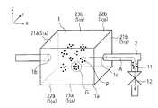
図1の基板処理システムは、集塵装置1と、循環流路2と、循環流路バルブ3と、ポンプ4と、タンク5と、第1流路11と、第1流路バルブ12と、第2流路13と、第2流路バルブ14と、基板処理装置15と、制御部16とを備えている。 The substrate processing system of FIG. 1 includes the
集塵装置1は、集塵対象の粒子Pを含む流体を収容する収容部1aと、収容部1aに流体を導入する導入口1bと、収容部1aから流体を排出する排出口1cとを備えている。流体の例は、水や薬液などの液体や、空気、炭酸ガス、アンモニアガス、シランガスなどの気体である。 The
循環流路2は、導入口1bおよび排出口1cに接続されている。循環流路バルブ3、ポンプ4、およびタンク5は、循環流路2に設けられている。循環流路2における流体の流通や流量は、循環流路バルブ3の開閉や開度を調整することで制御される。循環流路2内の流体は、ポンプ4により移送され、タンク5内に貯留され、収容部1aを導入口1bから排出口1cへと通過する。流体内の粒子Pは、収容部1a内で除去される。 The
図1は、互いに垂直なX方向、Y方向、およびZ方向を示している。本実施形態では、X方向およびY方向は集塵装置1の設置面に平行であり、Z方向は集塵装置1の設置面に垂直である。本明細書では、+Z方向を上方向として取り扱い、−Z方向を下方向として取り扱う。なお、本実施形態の−Z方向は、重力方向と一致していてもよいし、重力方向と一致していなくてもよい。 FIG. 1 shows X, Y, and Z directions perpendicular to one another. In the present embodiment, the X direction and the Y direction are parallel to the installation surface of the
本実施形態の収容部1aは、直方体形状の内壁面を有しており、具体的には、X方向に垂直で互いに対向する1対の第1壁面S1A、S1Bと、Y方向に垂直で互いに対向する1対の第2壁面S2A、S2Bと、Z方向に垂直で互いに対向する1対の第3壁面S3A、S3Bとを有している。導入口1bは、一方の第1壁面S1Aに設けられており、排出口1cは、他方の第1壁面S1Bに設けられている(図2参照)。図2は、第1実施形態の集塵装置1の構造を示す斜視図である。The
図1を再び参照し、基板処理システムの説明を続ける。 Referring back to FIG. 1, the description of the substrate processing system will be continued.
集塵装置1は、一方の第1壁面S1A付近に設けられた第1音源21aと、他方の第1壁面S1Bを形成している第1反射板21bとを備えている。集塵装置1はさらに、一方の第2壁面S2A付近に設けられた第2音源22aと、他方の第2壁面S2Bを形成している第2反射板22bとを備えている。集塵装置1はさらに、一方の第3壁面S3A付近に設けられた第3音源23aと、他方の第3壁面S3Bを形成している第3反射板23bとを備えている。音源21a、22a、23aは、1つ以上の音源の例である。
音源21a、22a、23aは、収容部1a内に音波を発生させる。音源21a、22a、23aの例は、圧電素子である。反射板21b、22b、23bは、音源21a、22a、23aからの音波を反射させる。反射板21b、22b、23bは、音波の反射率が高い材料で形成することが望ましい。音源21a、22a、23aからの音波は、収容部1a内の流体内を伝播し、反射板21b、22b、23bで反射される。 The
集塵装置1は、これらの音源と反射板により、1つ以上の節と1つ以上の腹とを有する定在音波を収容部1a内に発生させることができる。その結果、定在音波の節に向かう力が粒子Pに作用し、粒子Pが定在音波の節の付近にトラップされる。定在音波の節の個数は、何個でもよい。 The
音波の条件は、流体Pをトラップできれば、どのように設定してもよい。例えば、音波の周波数は1〜100MHzに設定され、音波の波長は10〜1000μmに設定され、音波の振幅は0.001〜0.1MPaに設定される。音波の条件は、流体の流速および粘度や、粒子Pの粒径を考慮して設定することが望ましい。音波の周波数は、可聴域内の周波数でも可聴域外の周波数でもよいが、本実施形態の音波は可聴域外の周波数を有している。流体が腐食性を有する場合には、収容部1a内の部品や部材の表面を保護膜で被覆してもよい。 The conditions of the sound wave may be set in any way as long as the fluid P can be trapped. For example, the frequency of the sound wave is set to 1 to 100 MHz, the wavelength of the sound wave is set to 10 to 1000 μm, and the amplitude of the sound wave is set to 0.001 to 0.1 MPa. The conditions of the sound wave are desirably set in consideration of the flow velocity and viscosity of the fluid and the particle size of the particles P. The frequency of the sound wave may be a frequency within the audible range or a frequency outside the audible range, but the sound wave of the present embodiment has a frequency outside the audible range. If the fluid is corrosive, the surfaces of the parts and members in the
なお、第1反射板21bは、音源に置き換えてもよい。すなわち、集塵装置1は、第1壁面S1A、S1Bの片面付近のみに音源を備えていてもよいし、第1壁面S1A、S1Bの両面付近に音源を備えていてもよい。同様に、第2反射板22bは音源に置き換えてもよいし、第3反射板23bは音源に置き換えてもよい。The
また、音源21a、22a、23aは、収容部1a内の流体に露出していてもよいし、収容部1a内の流体に露出していなくてもよい。前者の場合、音源21a、22a、23aの表面が、収容部1aの内壁面の一部を構成する。これは、反射板21b、22b、23bと置き換えられる音源についても同様である。 Further, the
第1流路11は循環流路2に接続されており、第1流路バルブ12は第1流路11に設けられている。第1流路11における流体の流通や流量は、第1流路バルブ12の開閉や開度を調整することで制御される。また、第2流路13は循環流路2に接続されており、第2流路バルブ14は第2流路13に設けられている。第2流路13における流体の流通や流量は、第2流路バルブ14の開閉や開度を調整することで制御される。第2流路13は、基板処理装置15に接続されている。 The
集塵装置1は、粒子Pを節の付近にトラップしつつ流体を排出することで、粒子Pが低減された流体を排出することができる。この場合、排出口1cから排出される流体中の粒子Pの濃度は、導入口1bから導入される流体中の粒子Pの濃度よりも低くなる。本実施形態の基板処理システムは、この流体が集塵装置1から排出される際に、第1流路バルブ12を閉じ、第2流路バルブ14を開く。その結果、この流体が第2流路13を介して基板処理装置15に供給される。第2流路13は、流体を基板処理装置15に供給するために使用される。 The
また、集塵装置1は、流体を節の付近にトラップされた粒子Pと共に排出することで、粒子Pが濃縮された流体を排出することができる。この場合、排出口1cから排出される流体中の粒子Pの濃度は、導入口1bから導入される流体中の粒子Pの濃度よりも高くなる。本実施形態の基板処理システムは、この流体が集塵装置1から排出される際に、第1流路バルブ12を開き、第2流路バルブ14を閉じる。その結果、この流体が第1流路11に供給される。第1流路11は、流体を基板処理装置15に供給せずに廃棄するために使用される。 Further, the
基板処理装置15は、収容部31と、保持部32と、回転軸33と、複数のチャックピン34と、ノズル35とを備えている。収容部31は、処理対象のウェハ(基板)Wを収容する。保持部32は、収容部31内のウェハWをチャックピン34により保持する。回転軸33は、矢印Rのように保持部32を回転させることで、ウェハWを回転させる。ノズル35は、第2流路13からの流体をウェハWに吐出する。 The
基板処理装置15は、第2流路13からの流体によりウェハWを処理する。例えば、基板処理装置15は、ウェハWを回転させながらウェハWに流体として洗浄液を供給することで、ウェハWを洗浄することができる。また、基板処理装置15は、ウェハWを回転させながらウェハWに流体としてリンス液を供給することで、ウェハWをリンスすることができる。本実施形態によれば、粒子Pが除去された流体によりウェハWを洗浄またはリンスすることができる。また、基板処理装置15は、ウェハWを回転させながらウェハWに流体として塗布液を供給することで、ウェハWに塗布膜を形成してもよい。 The
制御部16は、基板処理システムの動作を制御する。例えば、制御部16は、集塵装置1、ポンプ4、および基板処理装置15の動作や、循環流路バルブ3、第1流路バルブ12、および第2流路バルブ14の開閉および開度を制御する。 The
図3は、第1実施形態の音源および反射板の作用を説明するための斜視図である。 FIG. 3 is a perspective view for explaining the operation of the sound source and the reflector of the first embodiment.
図3(a)は、第1音源21aと第1反射板21bの作用を示している。集塵装置1は、第1音源21aから音波を発生し、第1反射板21bにより音波を反射することで、節X1、X2、X3を有する定在音波を発生させることができる。節X1、X2、X3の形状は、X方向に垂直な平面である。この定在音波の節の個数は、3個以外でもよい。 FIG. 3A shows the operation of the first
図3(b)は、第2音源22aと第2反射板22bの作用を示している。集塵装置1は、第2音源22aから音波を発生し、第2反射板22bにより音波を反射することで、節Y1、Y2、Y3を有する定在音波を発生させることができる。節Y1、Y2、Y3の形状は、Y方向に垂直な平面である。この定在音波の節の個数は、3個以外でもよい。 FIG. 3B shows the operation of the
図3(c)は、第3音源23aと第3反射板23bの作用を示している。集塵装置1は、第3音源23aから音波を発生し、第3反射板23bにより音波を反射することで、節Z1、Z2、Z3を有する定在音波を発生させることができる。節Z1、Z2、Z3の形状は、Z方向に垂直な平面である。この定在音波の節の個数は、3個以外でもよい。 FIG. 3C shows the operation of the third
図4は、第1実施形態の集塵装置1の動作を説明するための斜視図である。 FIG. 4 is a perspective view for explaining the operation of the
図4では、第1音源21aが節X1、X2を有する定在音波を発生させ、第2音源22aが節Y1、Y2を有する定在音波を発生させ、第3音源23aが節Z1、Z2を有する定在音波を発生させている(節Y1、Y2、Z1、Z2の図示は省略)。 In FIG. 4, the first
集塵装置1は、音源21a、22a、23aから音波を同時に発生させる。その結果、節X1、X2を有する定在音波と、節Y1、Y2を有する定在音波と、節Z1、Z2を有する定在音波とが合成されて、節X1、X2、Y1、Y2、Z1、Z2の交点に節Nを有する合成定在音波が発生する。図4の各節Nは、壁面S1A、S1B、S2A、S2B、S3A、S3Bに接触しない点形状を有している(ただし、図4の各節Nは、各節Nの発生位置を見やすくするために、便宜的に四角形で描かれている)。図4では、合成定在音波の節Nに向かう力が粒子Pに作用し、粒子Pが合成定在音波の節Nの付近にトラップされる。The
図4に示すように、集塵装置1は、粒子Pを節Nの付近にトラップしつつ流体を排出することで、粒子Pが低減された流体を排出することができる。この場合、排出口1cから排出される流体中の粒子Pの濃度は、導入口1bから導入される流体中の粒子Pの濃度よりも低くなる。この流体は、第2流路13を介して基板処理装置15に供給される。 As shown in FIG. 4, the
図5は、第1実施形態の集塵装置1の動作を説明するための別の斜視図である。 FIG. 5 is another perspective view for explaining the operation of the
図5は、各節Nの付近にトラップされた粒子Pの集合Gを示している。集塵装置1は、基板処理装置15によるウェハWの処理が終了すると、音源21a、22a、23aを停止し、収容部1a内の流体を排出する。これにより、集塵装置1は、流体を各節Nの付近にトラップされた粒子Pと共に排出することができる。 FIG. 5 shows a set G of particles P trapped near each node N. When the processing of the wafer W by the
図5に示すように、集塵装置1は、流体をこれらの粒子Pと共に排出することで、粒子Pが濃縮された流体を排出することができる。この場合、排出口1cから排出される流体中の粒子Pの濃度は、導入口1bから導入される流体中の粒子Pの濃度よりも高くなる。この流体は、矢印Aで示すように第1流路11に排出され、基板処理装置15に供給されずに廃棄される。 As shown in FIG. 5, the
図6は、第1実施形態の比較例の集塵装置1の動作を説明するための斜視図である。 FIG. 6 is a perspective view for explaining the operation of the
図6(a)の比較例の集塵装置1は、音源として第3音源23aのみを備えている。そのため、本比較例の各節Nは、壁面S1A、S1B、S2A、S2Bに接触する平面形の形状を有している。別言すると、本比較例の各節Nの形状は、壁面S1A、S1B、S2A、S2Bに端部を有する開曲面となっている。The
図6(b)の比較例の集塵装置1は、音源として第2および第3音源22a、23aのみを備えている。そのため、本比較例の各節Nは、壁面S1A、S1Bに接触する直線形の形状を有している。別言すると、本比較例の各節Nの形状は、壁面S1A、S1Bに端部を有する開曲線となっている。The
これらの比較例では、節Nの付近にトラップされた粒子Pが、端部付近で節Nから離脱することが問題となる。さらには、端部付近で節Nに近付く粒子Pが、トラップされずに節Nを通過することで、節Nから離脱することも問題となる。これらの場合、粒子Pは節Nに束縛されずに移動してしまう。その結果、粒子Pが排出口1cから排出されるなどの問題が生じ(矢印E1、E2を参照)、粒子Pのトラップ効率が低下してしまう。 In these comparative examples, it becomes a problem that the particle P trapped near the node N separates from the node N near the end. Furthermore, it becomes a problem that the particles P approaching the node N near the end part leave the node N by passing through the node N without being trapped. In these cases, the particle P moves without being bound by the node N. As a result, there arises a problem that the particles P are discharged from the
一方、図4の本実施形態の各節Nは、壁面S1A、S1B、S2A、S2B、S3A、S3Bに接触しておらず、壁面S1A、S1B、S2A、S2B、S3A、S3Bに端部を有していない。そのため、本実施形態によれば、各節Nの端部に起因する粒子Pの離脱の問題を回避することが可能となり、粒子Pのトラップ効率を向上させることが可能となる。On the other hand, each node N of the present embodiment in FIG. 4 is not in contact with the wall surfaces S1A , S1B , S2A , S2B , S3A , S3B , and the wall surfaces S1A , S1B , S2A , S2B ,S3A ,S3B have no end. Therefore, according to the present embodiment, it is possible to avoid the problem of the separation of the particles P caused by the end portions of the nodes N, and it is possible to improve the trap efficiency of the particles P.
このように、本実施形態では、流体中の粒子Pを音波を用いて除去する。よって、本実施形態によれば、流体中の粒子Pをフィルタを用いずに除去することが可能となり、フィルタの問題を回避することが可能となる。例えば、本実施形態によれば、フィルタの目詰まりや、フィルタでの流体の圧損や、フィルタを交換する際のコストや汚染の問題を回避することが可能となる。 Thus, in the present embodiment, particles P in the fluid are removed using sound waves. Therefore, according to the present embodiment, the particles P in the fluid can be removed without using a filter, and the problem of the filter can be avoided. For example, according to the present embodiment, it is possible to avoid the problems of clogging of the filter, pressure loss of fluid in the filter, cost and contamination when replacing the filter.
図7は、第1実施形態の集塵装置1内の定在音波について説明するための図である。 FIG. 7 is a view for explaining the standing sound waves in the
図7(a)は、図3(a)と同様に、第1音源21aと第1反射板21bとの間に発生する定在音波の一例を示している。符号λは、この定在音波の波長を表す。この定在音波から粒子Pに作用する力Fは、次の式(1)で与えられる。 Similarly to FIG. 3A, FIG. 7A shows an example of a standing sound wave generated between the first
F=V[B+(1−γ)]kA2/(ρc)・sin(2kx) ・・・(1)
ただし、Vは粒子Pの体積を表し、kは音波の波数を表し、Aは音波の振幅を表す。また、B、γ、ρ、cは流体の特性を表す値である。式(1)は、座標xに位置する粒子Pに作用する力Fを表す。F = V [B + (1-γ)] kA2 / (ρc) · sin (2kx) (1)
However, V represents the volume of the particle P, k represents the wave number of the sound wave, and A represents the amplitude of the sound wave. B, γ, ρ, and c are values representing the characteristics of the fluid. Equation (1) represents the force F acting on the particle P located at the coordinate x.
図7(b)は、座標xに位置する粒子Pに作用する力Fを表すグラフである。曲線C1、C2、C3はそれぞれ、定在音波の振幅Aが10μm、15μm、20μmの場合の力Fを示している。曲線C1、C2、C3のピークは、定在音波の腹にて粒子Pに作用する力Fを表す。式(1)や曲線C1、C2、C3から分かるように、力Fは、定在音波の波数kや振幅Aを大きくすることで増加させることが可能である。 FIG. 7B is a graph showing the force F acting on the particle P located at the coordinate x. Curves C1, C2, and C3 indicate forces F when the amplitude A of the standing sound wave is 10 μm, 15 μm, and 20 μm, respectively. The peaks of the curves C1, C2, C3 represent the force F acting on the particle P at the antinode of the standing sound wave. As understood from the equation (1) and the curves C1, C2 and C3, the force F can be increased by increasing the wave number k and the amplitude A of the standing sound wave.
以上のように、本実施形態の音源21a、22a、23aは、収容部1aの内壁面に接触しない節Nを有する定在音波を発生させ、定在音波の節Nの付近に粒子Pをトラップする。よって、本実施形態によれば、粒子Pのトラップ効率を向上させたり、フィルタの問題を回避するなど、流体中の粒子Pを適切に除去することが可能となる。 As described above, the
(第2実施形態)
図8は、第2実施形態の集塵装置1の構造を示す斜視図である。Second Embodiment
FIG. 8 is a perspective view showing the structure of the
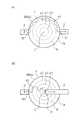
本実施形態の収容部1aは、円柱形状の内壁面を有しており、具体的には、X方向に垂直で互いに対向する1対の第1壁面S4A、S4Bと、X方向に延びる筒形状を有する第2壁面S5とを有している。導入口1bは、一方の第1壁面S4Aに設けられており、排出口1cは、他方の第1壁面S4Bに設けられている。The
集塵装置1は、一方の第1壁面S4A付近に設けられた第1音源24aと、他方の第1壁面S4Bを形成している第1反射板24bとを備えている。集塵装置1はさらに、第2壁面S5付近に設けられた第2音源25を備えている。第1および第2音源24a、25は、1つ以上の音源の例である。
第1および第2音源24a、25は、収容部1a内に音波を発生させる。第1反射板24bは、第1および第2音源24a、25からの音波を反射させる。集塵装置1は、これらの音源と反射板により、1つ以上の節と1つ以上の腹とを有する定在音波を収容部1a内に発生させることができる。その結果、定在音波の節に向かう力が粒子Pに作用し、粒子Pが定在音波の節の付近にトラップされる。 The first and
なお、第1反射板24bは、音源に置き換えてもよい。すなわち、集塵装置1は、第1壁面S4A、S4Bの片面付近のみに音源を備えていてもよいし、第1壁面S4A、S4Bの両面付近に音源を備えていてもよい。The
図9は、第2実施形態の音源および反射板の作用を説明するための斜視図である。 FIG. 9 is a perspective view for explaining the operation of the sound source and the reflector according to the second embodiment.
図9(a)は、第1音源24aと第1反射板24bの作用を示している。集塵装置1は、第1音源24aから音波を発生し、第1反射板24bにより音波を反射することで、節R1、R2、R3を有する定在音波を発生させることができる。節R1、R2、R3の形状は、X方向に垂直な平面である。この定在音波の節の個数は、3個以外でもよい。 FIG. 9A shows the operation of the first
図9(b)は、第2音源25の作用を示している。集塵装置1は、第2音源25から音波を発生することで、節θ1、θ2、θ3を有する定在音波を発生させることができる。節θ1、θ2、θ3は、X方向に延びる筒形状を有している。この定在音波の節の個数は、3個以外でもよい。 FIG. 9B shows the action of the
図9(c)では、第1音源24aが節R1、R2、R3を有する定在音波を発生させ、第2音源25が節θ1、θ2、θ3を有する定在音波を発生させている(これらの節の図示は省略)。 In FIG. 9C, the first
集塵装置1は、第1および第2音源24a、25から音波を同時に発生させる。その結果、節R1、R2、R3を有する定在音波と、節θ1、θ2、θ3を有する定在音波とが合成されて、節R1、R2、R3、θ1、θ2、θ3の交線に節Nを有する合成定在音波が発生する。図9(c)の各節Nの形状は、壁面S4A、S4B、S5に接触しない閉曲線(具体的には円環)となっている。図9(c)では、合成定在音波の節Nに向かう力が粒子Pに作用し、粒子Pが合成定在音波の節Nの付近にトラップされる。The
図9(c)の各節Nは、壁面S4A、S4B、S5に接触しておらず、壁面S4A、S4B、S5に端部を有していない。よって、本実施形態によれば、第1実施形態と同様に、各節Nの端部に起因する粒子Pの離脱の問題を回避することが可能となり、粒子Pのトラップ効率を向上させることが可能となる。なお、節Nの形状は、円環以外の閉曲線でもよい。Sections N in FIG. 9 (c), the wall surfaceS4A, S 4B, not in contact with theS 5, the wall surfaceS4A, S 4B, has no end toS 5. Therefore, according to the present embodiment, similarly to the first embodiment, it is possible to avoid the problem of the separation of the particles P caused by the ends of the nodes N, and to improve the trapping efficiency of the particles P. It becomes possible. The shape of the node N may be a closed curve other than a ring.
(第3実施形態)
図10は、第3実施形態の集塵装置1の構造を示す斜視図である。Third Embodiment
FIG. 10 is a perspective view showing the structure of the
本実施形態の収容部1aは、球形状の内壁面である第1壁面S6を有している。集塵装置1は、第1壁面S6付近に設けられた第1音源26を備えている。第1音源26は、1つ以上の音源の例である。Accommodating
集塵装置1は、第1音源26により、1つ以上の節と1つ以上の腹とを有する定在音波を収容部1a内に発生させることができる。その結果、定在音波の節に向かう力が粒子Pに作用し、粒子Pが定在音波の節の付近にトラップされる。 The
符号Cは、球形状の第1壁面S6の中心を示している。本実施形態では、導入口1bと中心Cとの距離が、排出口1cと中心Cとの距離と異なることが望ましい。図10では、導入口1bが第1壁面S6付近に設けられ、排出口1cが中心C付近に設けられることで、このような設定が実現されている。このような設定の詳細は、図11を参照して説明することにする。Symbol C indicates the center of the first wall surface S6 spherical. In the present embodiment, it is desirable that the distance between the
図11は、第3実施形態の集塵装置1の動作を説明するための断面図である。 FIG. 11 is a cross-sectional view for explaining the operation of the
図11(a)は、導入口1bと中心Cとの距離が、排出口1cと中心Cとの距離と同じである集塵装置1を示している。この集塵装置1は、1つ以上の節Nとして、球形状の節ρ1、ρ2、ρ3を有する定在音波を発生させることができる。この定在音波の節Nの個数は、3個以外でもよい。 FIG. 11A shows the
図11(a)の各節Nの形状は、第1壁面S6に接触しない閉曲面(具体的には球面)となっている。図11(a)では、定在音波の節Nに向かう力が粒子Pに作用し、粒子Pが定在音波の節Nの付近にトラップされる。The shape of the sections N of FIG. 11 (a), has a closed surface does not contact the first wall surface S6 (specifically spherical surface). In FIG. 11A, a force directed to the node N of the standing sound wave acts on the particle P, and the particle P is trapped in the vicinity of the node N of the standing sound wave.
図11(a)の各節Nは、第1壁面S6に接触しておらず、第1壁面S6に端部を有していない。よって、本実施形態によれば、第1および第2実施形態と同様に、各節Nの端部に起因する粒子Pの離脱の問題を回避することが可能となり、粒子Pのトラップ効率を向上させることが可能となる。なお、節Nの形状は、球面以外の閉曲面でもよい。Sections of FIG. 11 (a) N, is not in contact with the first wall surface S6, it does not have an end portion on the first wall surface S6. Therefore, according to the present embodiment, as in the first and second embodiments, it is possible to avoid the problem of the separation of the particles P caused by the ends of the nodes N, and the trapping efficiency of the particles P is improved. It becomes possible to make it. The shape of the node N may be a closed curved surface other than a spherical surface.
しかしながら、図11(a)では、導入口1bからの粒子Pは、いずれの節Nも通過せずに排出口1cに到達することができる(矢印A1を参照)。理由は、導入口1bと中心Cとの距離が、排出口1cと中心Cとの距離と同じであるからである。この場合、この粒子Pは節Nの付近にトラップされない可能性がある。 However, in FIG. 11 (a), the particle P from the
図11(b)は、導入口1bと中心Cとの距離が、排出口1cと中心Cとの距離と異なる集塵装置1を示している。この集塵装置1は、1つ以上の節Nとして、球形状の節ρ1、ρ2、ρ3を有する定在音波を発生させることができる。この定在音波の節Nの個数は、3個以外でもよい。 FIG. 11B shows the
図11(b)では、導入口1bからの粒子Pは、いずれの節Nも通過せずに排出口1cに到達することはできない(矢印A2を参照)。理由は、導入口1bと中心Cとの距離が、排出口1cと中心Cとの距離と異なるからである。これにより、図11(a)のように粒子Pがトラップされない可能性を低減することが可能となる。 In FIG. 11 (b), the particles P from the
なお、図11(b)の排出口1cは、中心Cの付近ではなく、中心Cと第1壁面S6との間に設けられていてもよい。この場合、導入口1bからの粒子Pは、第1壁面S6付近の節Nを通過し、中心C付近の節Nを通過せずに排出口1cに到達することができる。この粒子Pは、第1壁面S6付近の節Nによりトラップされる可能性が高い。The
(第4実施形態)
図12は、第4実施形態の集塵装置1の構造を示す斜視図である。Fourth Embodiment
FIG. 12 is a perspective view showing the structure of the
本実施形態の収容部1aは、直方体形状の内壁面を有しており、具体的には、X方向に垂直で互いに対向する1対の第1壁面S1A、S1Bと、Y方向に垂直で互いに対向する1対の第2壁面S2A、S2Bと、Z方向に垂直で互いに対向する1対の第3壁面S3A、S3Bとを有している。導入口1bは、一方の第1壁面S1Aに設けられており、排出口1cは、他方の第1壁面S1Bに設けられている。これは、第1実施形態と同様である。The
集塵装置1は、一方の第1壁面S1A付近に設けられた第1音源21aと、他方の第1壁面S1Bを形成している第1反射板21bとを備えている。第1音源21aは、1つ以上の音源の例である。
集塵装置1はさらに、第2壁面S2A、S2Bを形成している壁材27a、27bと、第3壁面S3A、S3Bを形成している壁材28a、28bとを備えている。第2および第3壁面S2A、S2B、S3A、S3Bは、収容部の壁面の所定部分の例である。
図13は、第4実施形態の音源、反射板、および壁材の作用を説明するための断面図である。 FIG. 13: is sectional drawing for demonstrating the effect | action of the sound source of 4th Embodiment, a reflecting plate, and a wall material.
本実施形態の集塵装置1は、1つ以上の節Nとして、節X1、X2、X3を有する定在音波を発生させることができる。その結果、これらの節Nに向かう力が粒子Pに作用し、粒子Pがこれらの節Nの付近にトラップされる。 The
本実施形態の集塵装置1は、音源として第1音源21aのみを備えている。そのため、本実施形態の各節Nは、壁面S2A、S2B、S3A、S3Bに接触する平面形の形状を有している。別言すると、本実施形態の各節Nの形状は、壁面S2A、S2B、S3A、S3Bに端部を有する開曲面となっている。これは、図6(a)の比較例の場合と同様である。The
図6(a)の比較例では、節Nの付近にトラップされた粒子Pが、端部付近で節Nから離脱することが問題となる。さらには、端部付近で節Nに近付く粒子Pが、トラップされずに節Nを通過することで、節Nから離脱することも問題となる。これらの場合、粒子Pは節Nに束縛されずに移動してしまう。その結果、粒子Pが排出口1cから排出されるなどの問題が生じ、粒子Pのトラップ効率が低下してしまう。 In the comparative example of FIG. 6A, the problem is that the particles P trapped in the vicinity of the node N are detached from the node N near the end. Furthermore, it becomes a problem that the particles P approaching the node N near the end part leave the node N by passing through the node N without being trapped. In these cases, the particle P moves without being bound by the node N. As a result, there arises a problem that the particles P are discharged from the
そのため、本実施形態の壁面S2A、S2B、S3A、S3Bは、壁面S2A、S2B、S3A、S3B付近の節Nから粒子Pが離脱することを阻止可能な壁材27a、27b、28a、28bで形成されている。このような壁材27a、27b、28a、28bの例は、粒子Pの封止性が良い、壁面付近で粒子Pが移動しにくいなどの性質を持つ壁材である。本実施形態によれば、各節Nの端部が壁材27a、27b、28a、28bに接触することで、各節Nの端部に起因する粒子Pの離脱の問題を回避することが可能となり、粒子Pのトラップ効率を向上させることが可能となる。Therefore, the wall surfaces S2A , S2B , S3A , and S3B of the present embodiment can prevent the particles P from being detached from the node N near the wall surfaces S2A , S2B , S3A , and
なお、壁材27a、27b、28a、28bは、壁面S2A、S2B、S3A、S3B付近の節Nからの粒子Pの離脱を阻止可能な別の部材(冶具)に置き換えてもよい。このような部材の例は、保護膜や塗布膜などである。Incidentally,
また、本実施形態の集塵装置1は、音源として第1および第2音源21a、22aのみを備えていてもよい。この場合の各節Nは、壁面S3A、S3Bに接触する直線形の形状を有する。別言すると、この場合の各節Nの形状は、壁面S3A、S3Bに端部を有する開曲線となる。これは、図6(b)の比較例の場合と同様である。この場合、本実施形態の壁面S3A、S3Bは、壁面S3A、S3B付近の節Nから粒子Pが離脱することを阻止可能な壁材28a、28bで形成される。Moreover, the
(第5実施形態)
図14は、第5実施形態の集塵装置1の構造を示す斜視図である。Fifth Embodiment
FIG. 14 is a perspective view showing the structure of the
本実施形態の収容部1aは、円柱形状の内壁面を有しており、具体的には、X方向に垂直で互いに対向する1対の第1壁面S4A、S4Bと、X方向に延びる筒形状を有する第2壁面S5とを有している。導入口1bは、一方の第1壁面S4Aに設けられており、排出口1cは、他方の第1壁面S4Bに設けられている。これは、第2実施形態と同様である。The
集塵装置1は、一方の第1壁面S4A付近に設けられた第1音源24aと、他方の第1壁面S4Bを形成している第1反射板24bとを備えている。第1音源24aは、1つ以上の音源の例である。
集塵装置1はさらに、第2壁面S5を形成している壁材29を備えている。第2壁面S5は、収容部の壁面の所定部分の例である。
本実施形態の集塵装置1は、音源として第1音源24aのみを備えている。そのため、本実施形態の各節Nは、図9(a)の節R1、R2、R3と同様に、壁面S5に接触する平面形の形状を有する(不図示)。別言すると、本実施形態の各節Nの形状は、壁面S5に端部を有する開曲面となる。そのため、本実施形態の壁面S5は、第4実施形態の場合と同様の理由から、壁面S5付近の節Nから粒子Pが離脱することを阻止可能な壁材29で形成されている。これにより、粒子Pのトラップ効率を向上させることが可能となる。The
なお、第3実施形態の図11(b)では、排出口1cが中心C付近に位置するため、循環流路2の一部が収容部1a内に位置している。そのため、節Nが循環流路2の外周面に接触している。よって、収容部1a内の循環流路2の外周面は、第4および第5実施形態のような壁材で形成してもよい。 In addition, in FIG.11 (b) of 3rd Embodiment, since the
(第6実施形態)
図15は、第6実施形態の半導体装置の製造方法を示す断面図である。Sixth Embodiment
FIG. 15 is a cross-sectional view illustrating the method of manufacturing the semiconductor device according to the sixth embodiment.
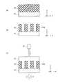
図15(a)は、図1のウェハWを示している。ウェハWは、半導体基板41と、半導体基板41上に形成された被加工層42とを備えている。被加工層42は、半導体基板41上に直接形成されてもよいし、半導体基板41上に他の層を介して形成されてもよい。被加工層42は、図15(a)では絶縁膜であるが、導体層や半導体層でもよい。FIG. 15 (a) shows the wafer W of FIG. The wafer W includes a
本実施形態では、半導体基板41上に被加工層42を形成した後、被加工層42をエッチングにより加工する(図15(b))。その結果、被加工層42が複数の凸部42aに加工される。凸部42aの例は、配線パターンや、配線パターンを形成するためのハードマスクパターンである。 In this embodiment, after forming the
次に、ウェハWを基板処理装置15内に搬入する。そして、基板処理装置15は、矢印RのようにウェハWを回転させながら、ノズル35からウェハWに基板処理液43を吐出する(図15(c))。基板処理液43の例は、集塵装置1からの流体であり、例えば洗浄液やリンス液である。本実施形態では、洗浄液によりウェハWを洗浄することや、リンス液によりウェハWをリンスすることが可能である。 Next, the wafer W is loaded into the
その後、本実施形態ではウェハWの加工が継続される。このようにして、ウェハWから半導体装置が製造される。 Thereafter, in the present embodiment, the processing of the wafer W is continued. Thus, a semiconductor device is manufactured from the wafer W.
以上、いくつかの実施形態を説明したが、これらの実施形態は、例としてのみ提示したものであり、発明の範囲を限定することを意図したものではない。本明細書で説明した新規な装置、システム、および方法は、その他の様々な形態で実施することができる。また、本明細書で説明した装置、システム、および方法の形態に対し、発明の要旨を逸脱しない範囲内で、種々の省略、置換、変更を行うことができる。添付の特許請求の範囲およびこれに均等な範囲は、発明の範囲や要旨に含まれるこのような形態や変形例を含むように意図されている。 While certain embodiments have been described above, these embodiments have been presented by way of example only, and are not intended to limit the scope of the invention. The novel apparatus, systems, and methods described herein may be implemented in various other forms. Furthermore, various omissions, substitutions and changes in the form of the devices, systems, and methods described herein may be made without departing from the spirit of the invention. The appended claims and their equivalents are intended to include such forms and modifications as fall within the scope and spirit of the invention.
1:集塵装置、1a:収容部、1b:導入口、1c:排出口、
2:循環流路、3:循環流路バルブ、4:ポンプ、5:タンク、
11:第1流路、12:第1流路バルブ、13:第2流路、14:第2流路バルブ、
15:基板処理装置、16:制御部、
21a:第1音源、21b:第1反射板、
22a:第2音源、22b:第2反射板、
23a:第3音源、23b:第3反射板、
24a:第1音源、24b:第1反射板、25:第2音源、
26:第1音源、27a、27b、28a、28b、29:壁材、
31:収容部、32:保持部、33:回転軸、34:チャックピン、35:ノズル、
41:半導体基板、42:被加工層、42a:凸部、43:基板処理液1: dust collector, 1a: accommodating portion, 1b: introduction port, 1c: discharge port,
2: circulation channel, 3: circulation channel valve, 4: pump, 5: tank,
11: 1st flow path, 12: 1st flow path valve, 13: 2nd flow path, 14: 2nd flow path valve,
15: Substrate processing apparatus, 16: Control unit,
21a: first sound source, 21b: first reflector,
22a: second sound source, 22b: second reflector,
23a: third sound source, 23b: third reflector,
24a: first sound source, 24b: first reflector, 25: second sound source,
26: first sound source, 27a, 27b, 28a, 28b, 29: wall material,
31: accommodation portion, 32: holding portion, 33: rotation axis, 34: chuck pin, 35: nozzle,
41: Semiconductor substrate, 42: Processed layer, 42a: convex portion, 43: substrate processing liquid
Claims (5)
Translated fromJapanese少なくとも1つの節を有する定在音波を前記収容部内に発生させ、前記粒子を前記節の付近にトラップする1つ以上の音源と、
前記収容部に設けられた排出口であって、前記粒子が前記トラップにより低減された前記流体により基板を処理する基板処理装置に前記流体を排出する排出口とを備え、
前記音源は、前記節が前記収容部の壁面に接触しないように、または前記節が前記収容部の壁面の所定部分に接触するように、前記定在音波を発生させ、
前記所定部分は、前記所定部分付近の前記節からの前記粒子の離脱を阻止する部材で形成されている、集塵装置。A storage unit for storing a fluid containing particles to be collected;
One or more sound sources for generating a standing sound wave having at least one node in the receptacle and trapping the particles in the vicinity of the node;
A discharge port provided in the storage unit, the discharge port discharging the fluid to a substrate processing apparatus that processes the substrate with the fluidin which the particles are reduced by the trap ;
The sound source generates the standing sound wave so that the node does not contact the wall surface of the housing part or the node contacts a predetermined part of the wall surface of the housing part,
The dust collecting apparatus, wherein the predetermined portion is formed of a member that prevents the particles from detaching from the node near the predetermined portion.
前記流体は、前記導入口を介して前記収容部に導入され、前記排出口を介して前記収容部から排出されるまでの過程において、前記節の少なくとも1つを通過する、請求項1または2に記載の集塵装置。The storage unit includes an introduction port for introducing the fluid into the storage unit, and the discharge port for discharging the fluid whose particles are concentrated or reduced by the trap from the storage unit.
The fluid may pass through at least one of the nodes in a process of being introduced into the housing through the inlet and being discharged from the housing through the outlet. The dust collector described in 1.
少なくとも1つの節を有する定在音波を前記収容部内に発生させ、前記粒子を前記節の付近にトラップする1つ以上の音源と、
前記収容部から排出された前記流体により基板を処理する基板処理装置とを備え、
前記音源は、前記節が前記収容部の壁面に接触しないように、または前記節が前記収容部の壁面の所定部分に接触するように、前記定在音波を発生させ、
前記所定部分は、前記所定部分付近の前記節からの前記粒子の離脱を阻止する部材で形成されている、基板処理システム。A storage unit for storing a fluid containing particles to be collected;
One or more sound sources that generate standing sound waves having at least one node in the housing and trap the particles in the vicinity of the nodes;
A substrate processing apparatus for processing a substrate with the fluid discharged from the container,
The sound source generates the standing sound wave so that the node does not contact the wall surface of the housing part or the node contacts a predetermined part of the wall surface of the housing part,
The substrate processing system, wherein the predetermined portion is formed of a member that prevents separation of the particles from the node in the vicinity of the predetermined portion.
前記基板処理装置は、前記第2流路からの前記流体により前記基板を処理する、請求項4に記載の基板処理システム。The container discharges the fluid in which the particles are concentrated by the trap to the first flow path, and discharges the fluid in which the particles are reduced by the trap to the second flow path,
The substrate processing system according to claim 4, wherein the substrate processing apparatus processes the substrate with the fluid from the second flow path.
Priority Applications (2)
| Application Number | Priority Date | Filing Date | Title |
|---|---|---|---|
| JP2016034316AJP6554045B2 (en) | 2016-02-25 | 2016-02-25 | Dust collector and substrate processing system |
| US15/239,243US10290490B2 (en) | 2016-02-25 | 2016-08-17 | Dust collecting apparatus, substrate processing system, and method of manufacturing semiconductor device |
Applications Claiming Priority (1)
| Application Number | Priority Date | Filing Date | Title |
|---|---|---|---|
| JP2016034316AJP6554045B2 (en) | 2016-02-25 | 2016-02-25 | Dust collector and substrate processing system |
Publications (2)
| Publication Number | Publication Date |
|---|---|
| JP2017148747A JP2017148747A (en) | 2017-08-31 |
| JP6554045B2true JP6554045B2 (en) | 2019-07-31 |
Family
ID=59679835
Family Applications (1)
| Application Number | Title | Priority Date | Filing Date |
|---|---|---|---|
| JP2016034316AActiveJP6554045B2 (en) | 2016-02-25 | 2016-02-25 | Dust collector and substrate processing system |
Country Status (2)
| Country | Link |
|---|---|
| US (1) | US10290490B2 (en) |
| JP (1) | JP6554045B2 (en) |
Families Citing this family (6)
| Publication number | Priority date | Publication date | Assignee | Title |
|---|---|---|---|---|
| JP6640781B2 (en)* | 2017-03-23 | 2020-02-05 | キオクシア株式会社 | Semiconductor manufacturing equipment |
| JP7429052B2 (en)* | 2018-12-11 | 2024-02-07 | アエニティス テクノロジーズ | System and method for varying the concentration of particles in a fluid |
| CN113905801A (en)* | 2019-06-28 | 2022-01-07 | 韩国生产技术研究院 | Method and device for agglomerating fine particles |
| CN111495098A (en)* | 2020-01-22 | 2020-08-07 | 广东工业大学 | Two-dimensional aggregation method and aggregation device for micron particles |
| KR20230009921A (en)* | 2020-05-14 | 2023-01-17 | 도쿄엘렉트론가부시키가이샤 | Liquid supply mechanism, substrate processing apparatus, and substrate processing method |
| TWI880753B (en)* | 2024-05-23 | 2025-04-11 | 銳澤實業股份有限公司 | Dust collection device |
Family Cites Families (25)
| Publication number | Priority date | Publication date | Assignee | Title |
|---|---|---|---|---|
| US2215484A (en)* | 1938-10-10 | 1940-09-24 | Us Government | Sonic flocculator and method of flocculating smoke or the like |
| GB8612759D0 (en)* | 1986-05-27 | 1986-07-02 | Unilever Plc | Manipulating particulate matter |
| JP2700058B2 (en) | 1996-01-23 | 1998-01-19 | 工業技術院長 | Non-contact micromanipulation method using ultrasonic waves |
| JPH1082723A (en) | 1996-09-06 | 1998-03-31 | Hitachi Ltd | Particle processing equipment |
| JP2899691B2 (en) | 1997-10-03 | 1999-06-02 | 工業技術院長 | Non-contact micromanipulation method |
| JPH11197491A (en)* | 1998-01-13 | 1999-07-27 | Hitachi Ltd | Particle processing method and particle processing apparatus |
| JP2001157999A (en) | 1999-12-02 | 2001-06-12 | Fuji Xerox Co Ltd | Noncontact micromanipulation device and method |
| JP4505624B2 (en)* | 2002-06-21 | 2010-07-21 | 独立行政法人産業技術総合研究所 | Non-contact filtering method and apparatus using ultrasonic waves |
| GB0223562D0 (en) | 2002-10-10 | 2002-11-20 | Secr Defence | Apparatus for moving particles |
| JP2004181347A (en) | 2002-12-03 | 2004-07-02 | Matsuura Machinery Corp | Method for removing solid particle by using ultrasonic wave |
| JP4691718B2 (en)* | 2004-06-02 | 2011-06-01 | 本多電子株式会社 | Separation apparatus and liquid fractionation apparatus using the same |
| SE528313C2 (en) | 2004-09-24 | 2006-10-17 | Spectronic Ab | Method and apparatus for separating particles using ultrasonic waves |
| JP2007229557A (en)* | 2006-02-28 | 2007-09-13 | Keio Gijuku | Method and apparatus for continuous separation of suspended particulates |
| EP2479552B1 (en) | 2007-04-02 | 2015-09-02 | Acoustic Cytometry Systems, Inc. | Methods for enhanced analysis of acoustic field focused cells and particles |
| US7837040B2 (en) | 2007-04-09 | 2010-11-23 | Los Alamos National Security, Llc | Acoustic concentration of particles in fluid flow |
| US8273302B2 (en) | 2007-05-15 | 2012-09-25 | Panasonic Corporation | Component separation device |
| US8865003B2 (en) | 2008-09-26 | 2014-10-21 | Abbott Laboratories | Apparatus and method for separation of particles suspended in a liquid from the liquid in which they are suspended |
| CN102933280B (en)* | 2010-06-04 | 2016-11-02 | 英派尔科技开发有限公司 | Sound-driving nanoparticle concentrator |
| WO2012017976A1 (en)* | 2010-08-02 | 2012-02-09 | Murata Mitsuo | Apparatus for continuously separating foreign substance from solution |
| US8679338B2 (en)* | 2010-08-23 | 2014-03-25 | Flodesign Sonics, Inc. | Combined acoustic micro filtration and phononic crystal membrane particle separation |
| JP2012217876A (en) | 2011-04-04 | 2012-11-12 | National Institute Of Advanced Industrial Science & Technology | Noncontact cleaning method using ultrasonic wave |
| US8727129B2 (en) | 2011-08-16 | 2014-05-20 | Lawrence Livermore National Security, Llc. | Microfluidic ultrasonic particle separators with engineered node locations and geometries |
| JP6064640B2 (en) | 2013-02-07 | 2017-01-25 | 株式会社Ihi | Solid-liquid separation method and apparatus |
| WO2015172095A1 (en)* | 2014-05-08 | 2015-11-12 | Flodesign Sonics, Inc. | Acoustophoretic device with piezoelectric transducer array |
| JP2017140588A (en)* | 2016-02-10 | 2017-08-17 | パナソニックIpマネジメント株式会社 | Dust collector |
- 2016
- 2016-02-25JPJP2016034316Apatent/JP6554045B2/enactiveActive
- 2016-08-17USUS15/239,243patent/US10290490B2/enactiveActive
Also Published As
| Publication number | Publication date |
|---|---|
| JP2017148747A (en) | 2017-08-31 |
| US20170250069A1 (en) | 2017-08-31 |
| US10290490B2 (en) | 2019-05-14 |
Similar Documents
| Publication | Publication Date | Title |
|---|---|---|
| JP6554045B2 (en) | Dust collector and substrate processing system | |
| US8888925B2 (en) | Nozzle, substrate processing apparatus, and substrate processing method | |
| JP6786732B2 (en) | Sub-nanometer level substrate cleaning mechanism | |
| JP6786730B2 (en) | Sub-nanometer level optical-based substrate cleaning mechanism | |
| CN105408983A (en) | Vertical non-rotating processing chamber | |
| CN110603628B (en) | Removal of treated sewage | |
| CN101563761A (en) | Megasonic precision cleaning of semiconductor processing equipment components and parts | |
| TWI617369B (en) | Device for substrate edge cleaning | |
| TWI642492B (en) | Ultrasonic cleaning method and equipment thereof | |
| US20200388511A1 (en) | Substrate processing apparatus | |
| CN103426799A (en) | Dual medium filter for ion and particle filtering during semiconductor processing | |
| KR20160136493A (en) | An ultrasonic transmitter having piezoelectric element capable of transverse prevention and ultrasonic cleaning device including the same | |
| KR102218496B1 (en) | Trap apparatus and exhaust system using the same, and substrate processing apparatus | |
| TW202016354A (en) | Apparatus and method for pumping gases from a chamber | |
| JP6412385B2 (en) | Conditioning unit, buff processing module, substrate processing apparatus, and dress rinse method | |
| KR20070084279A (en) | Wafer wet processing apparatus and method | |
| JP2014165349A (en) | Substrate processing device, and substrate processing method | |
| TWI528436B (en) | Acoustic energy system, method and apparatus for processing flat articles | |
| KR20220015549A (en) | filter device | |
| JP7454989B2 (en) | Substrate processing equipment | |
| TW201806036A (en) | Liquid filtering in removing photoresist from a wafer | |
| KR101677037B1 (en) | Rinsing and drying device | |
| TWI788018B (en) | Semiconductor processing system particle removal method in semiconductor fabrication process | |
| JP7094123B2 (en) | Cleaning tools and equipment | |
| KR101246613B1 (en) | Remote plasma system having particles filter on pipe connected process chamber |
Legal Events
| Date | Code | Title | Description |
|---|---|---|---|
| A711 | Notification of change in applicant | Free format text:JAPANESE INTERMEDIATE CODE: A712 Effective date:20170601 | |
| A621 | Written request for application examination | Free format text:JAPANESE INTERMEDIATE CODE: A621 Effective date:20180131 | |
| A711 | Notification of change in applicant | Free format text:JAPANESE INTERMEDIATE CODE: A712 Effective date:20180904 | |
| A131 | Notification of reasons for refusal | Free format text:JAPANESE INTERMEDIATE CODE: A131 Effective date:20180928 | |
| A521 | Request for written amendment filed | Free format text:JAPANESE INTERMEDIATE CODE: A523 Effective date:20181105 | |
| A131 | Notification of reasons for refusal | Free format text:JAPANESE INTERMEDIATE CODE: A131 Effective date:20190423 | |
| A521 | Request for written amendment filed | Free format text:JAPANESE INTERMEDIATE CODE: A523 Effective date:20190516 | |
| TRDD | Decision of grant or rejection written | ||
| A01 | Written decision to grant a patent or to grant a registration (utility model) | Free format text:JAPANESE INTERMEDIATE CODE: A01 Effective date:20190607 | |
| A61 | First payment of annual fees (during grant procedure) | Free format text:JAPANESE INTERMEDIATE CODE: A61 Effective date:20190705 | |
| R150 | Certificate of patent or registration of utility model | Ref document number:6554045 Country of ref document:JP Free format text:JAPANESE INTERMEDIATE CODE: R150 | |
| S531 | Written request for registration of change of domicile | Free format text:JAPANESE INTERMEDIATE CODE: R313531 | |
| S533 | Written request for registration of change of name | Free format text:JAPANESE INTERMEDIATE CODE: R313533 | |
| R350 | Written notification of registration of transfer | Free format text:JAPANESE INTERMEDIATE CODE: R350 |