JP6551626B2 - Method of melting high manganese steel - Google Patents
Method of melting high manganese steelDownload PDFInfo
- Publication number
- JP6551626B2 JP6551626B2JP2019506740AJP2019506740AJP6551626B2JP 6551626 B2JP6551626 B2JP 6551626B2JP 2019506740 AJP2019506740 AJP 2019506740AJP 2019506740 AJP2019506740 AJP 2019506740AJP 6551626 B2JP6551626 B2JP 6551626B2
- Authority
- JP
- Japan
- Prior art keywords
- manganese
- molten metal
- steel
- source
- concentration
- Prior art date
- Legal status (The legal status is an assumption and is not a legal conclusion. Google has not performed a legal analysis and makes no representation as to the accuracy of the status listed.)
- Active
Links
Images


Classifications
- C—CHEMISTRY; METALLURGY
- C21—METALLURGY OF IRON
- C21C—PROCESSING OF PIG-IRON, e.g. REFINING, MANUFACTURE OF WROUGHT-IRON OR STEEL; TREATMENT IN MOLTEN STATE OF FERROUS ALLOYS
- C21C1/00—Refining of pig-iron; Cast iron
- C—CHEMISTRY; METALLURGY
- C21—METALLURGY OF IRON
- C21C—PROCESSING OF PIG-IRON, e.g. REFINING, MANUFACTURE OF WROUGHT-IRON OR STEEL; TREATMENT IN MOLTEN STATE OF FERROUS ALLOYS
- C21C5/00—Manufacture of carbon-steel, e.g. plain mild steel, medium carbon steel or cast steel or stainless steel
- C21C5/28—Manufacture of steel in the converter
- C—CHEMISTRY; METALLURGY
- C21—METALLURGY OF IRON
- C21C—PROCESSING OF PIG-IRON, e.g. REFINING, MANUFACTURE OF WROUGHT-IRON OR STEEL; TREATMENT IN MOLTEN STATE OF FERROUS ALLOYS
- C21C7/00—Treating molten ferrous alloys, e.g. steel, not covered by groups C21C1/00 - C21C5/00
- C21C7/0068—Treating molten ferrous alloys, e.g. steel, not covered by groups C21C1/00 - C21C5/00 by introducing material into a current of streaming metal
- C—CHEMISTRY; METALLURGY
- C21—METALLURGY OF IRON
- C21C—PROCESSING OF PIG-IRON, e.g. REFINING, MANUFACTURE OF WROUGHT-IRON OR STEEL; TREATMENT IN MOLTEN STATE OF FERROUS ALLOYS
- C21C7/00—Treating molten ferrous alloys, e.g. steel, not covered by groups C21C1/00 - C21C5/00
- C21C7/04—Removing impurities by adding a treating agent
- C21C7/06—Deoxidising, e.g. killing
- C—CHEMISTRY; METALLURGY
- C21—METALLURGY OF IRON
- C21C—PROCESSING OF PIG-IRON, e.g. REFINING, MANUFACTURE OF WROUGHT-IRON OR STEEL; TREATMENT IN MOLTEN STATE OF FERROUS ALLOYS
- C21C7/00—Treating molten ferrous alloys, e.g. steel, not covered by groups C21C1/00 - C21C5/00
- C21C7/04—Removing impurities by adding a treating agent
- C21C7/064—Dephosphorising; Desulfurising
- C—CHEMISTRY; METALLURGY
- C21—METALLURGY OF IRON
- C21C—PROCESSING OF PIG-IRON, e.g. REFINING, MANUFACTURE OF WROUGHT-IRON OR STEEL; TREATMENT IN MOLTEN STATE OF FERROUS ALLOYS
- C21C7/00—Treating molten ferrous alloys, e.g. steel, not covered by groups C21C1/00 - C21C5/00
- C21C7/04—Removing impurities by adding a treating agent
- C21C7/068—Decarburising
- C—CHEMISTRY; METALLURGY
- C21—METALLURGY OF IRON
- C21C—PROCESSING OF PIG-IRON, e.g. REFINING, MANUFACTURE OF WROUGHT-IRON OR STEEL; TREATMENT IN MOLTEN STATE OF FERROUS ALLOYS
- C21C7/00—Treating molten ferrous alloys, e.g. steel, not covered by groups C21C1/00 - C21C5/00
- C21C7/10—Handling in a vacuum
Landscapes
- Chemical & Material Sciences (AREA)
- Engineering & Computer Science (AREA)
- Materials Engineering (AREA)
- Metallurgy (AREA)
- Organic Chemistry (AREA)
- Multimedia (AREA)
- Manufacturing & Machinery (AREA)
- Treatment Of Steel In Its Molten State (AREA)
- Carbon Steel Or Casting Steel Manufacturing (AREA)
Description
Translated fromJapanese本発明は、高マンガン鋼の溶製方法に関する。 The present invention relates to a method of melting high manganese steel.
マンガンは、鋼中に添加することにより、鋼材料の強度を向上させる利点がある。また、マンガンは、不可避的不純物として鋼中に残留する硫黄と反応してMnSを形成し、有害なFeSの生成を防止して鋼材料における硫黄の影響を抑制するなどの利点がある。このことから、鋼材料の大半は、マンガンを含有している。近年では、構造物の軽量化を目的として、高い引張強さと高い加工性とを両立させた、炭素含有量が低く、マンガン含有量が高い、低炭素・高マンガン鋼が開発され、ラインパイプ用鋼板や自動車用鋼板などとして広く使用されている。 Manganese has the advantage of improving the strength of the steel material by adding it to the steel. Also, manganese reacts with sulfur remaining in the steel as an unavoidable impurity to form MnS, and has the advantage of preventing the formation of harmful FeS and suppressing the influence of sulfur in the steel material. From this, most steel materials contain manganese. In recent years, low carbon and high manganese steels with low carbon content and high manganese content have been developed for the purpose of reducing the weight of structures, combining high tensile strength and high workability. It is widely used as a steel plate or a steel plate for automobiles.
製鋼工程において、溶鋼中のマンガン濃度を調整するために用いるマンガン源としては、マンガン鉱石や高炭素フェロマンガン(炭素含有量:7.5質量%以下)、中炭素フェロマンガン(炭素含有量:2.0質量%以下)、低炭素フェロマンガン(炭素含有量:1.0質量%以下)、シリコマンガン(炭素含有量:2.0質量%以下)、金属マンガン(炭素含有量:0.01質量%以下)などが一般的に用いられる。また、これらのマンガン源では、マンガン鉱石を除いて、炭素含有量が低くなるほどに高価となる。従って、製造コストの低減を目的として、安価なマンガン源である、マンガン鉱石や高炭素フェロマンガンを使用してマンガン含有鋼を溶製する方法が提案されている。 Manganese ore, high carbon ferromanganese (carbon content: 7.5% by mass or less), medium carbon ferromanganese (carbon content: 2) as a manganese source used to adjust the manganese concentration in the molten steel in the steelmaking process 0.0 mass%), low carbon ferromanganese (carbon content: 1.0 mass% or less), silicomanganese (carbon content: 2.0 mass% or less), metal manganese (carbon content: 0.01 mass%) % Or less) is generally used. Moreover, these manganese sources become expensive as the carbon content decreases, except for manganese ore. Therefore, for the purpose of reducing the manufacturing cost, a method of melting a manganese-containing steel using manganese ore and high carbon ferromanganese, which are inexpensive manganese sources, has been proposed.
例えば、特許文献1には、高マンガン鋼を溶製する方法として、転炉の吹錬終了後、底吹きガスによるリンシング処理を行ってから取鍋へ出鋼する際に、炭素濃度が1.0質量%以上の高炭素フェロマンガンを投入した後にアルミニウムを投入して脱酸処理し、その後、RHガス脱ガス処理を施す方法が提案されている。
また、特許文献2には、高マンガン鋼を溶製する方法として、マンガン鉱石を使用して、マンガン鉱石を還元しながら溶銑の脱炭精錬を行ない、脱炭終了後はアルミニウムによる溶鋼の脱酸処理を施さないまま溶鋼を真空脱ガス設備に搬送し、酸素ガスと不活性ガスとの混合ガスを吹き付けて脱炭処理を施す溶製方法が提案されている。
さらに、特許文献3には、高マンガン鋼を溶製する方法として、マンガン濃度が8質量%以上の高Mn溶銑を、0.1質量%以下の炭素濃度になるまで減圧下で脱炭精錬する際に、精錬気体を搬送ガスとして、Mn酸化物を含有する粉体状の脱炭精錬用添加剤を溶銑に吹き付ける方法が提案されている。For example, in Patent Document 1, as a method of melting high manganese steel, the carbon concentration is 1. when the steel is discharged to a ladle after rinsing with a bottom blowing gas after the completion of the converter blowing. A method has been proposed in which 0% by mass or more of high carbon ferromanganese is added, then aluminum is added to perform deoxidation treatment, and then RH gas degassing treatment is performed.
Further, in
Furthermore, in
ところで、特許文献1〜3の高マンガン鋼の溶製方法では、転炉での溶銑の脱炭吹錬時に転炉内に投入したマンガン鉱石を還元したり、転炉からの出鋼時や取鍋精錬時、真空脱ガス精錬時にマンガン源を溶鋼に添加したりすることによって溶鋼のマンガン濃度を上げている。
しかしながら、このような溶製方法において、脱炭吹錬時あるいは出鋼時にマンガン源を添加した場合、添加されたマンガン源の歩留りが低いため、多量のマンガン源を添加する必要があり、処理時間の増加とマンガンコストの増加が問題となる。また、出鋼時や取鍋精錬時、真空脱ガス精錬時にマンガン源を添加する場合、マンガン源の溶解による熱ロスが発生するため、転炉以降のプロセスにて溶鋼を昇熱させる必要が出てくる。しかし、取鍋精錬装置や真空脱ガス装置による溶鋼の昇熱処理は、転炉での昇熱処理に比べて効率が悪く処理に掛かるコストの増加が問題となる。特に、マンガン濃度が5質量%以上の高マンガン鋼では、これらの問題が顕著となる。By the way, in the method of melting high manganese steel disclosed in Patent Documents 1 to 3, manganese ore charged into the converter during the decarburization blowing of hot metal in the converter is reduced, or when the steel is removed from the converter or removed. At the time of pot smelting, the manganese concentration of the molten steel is raised by adding a manganese source to the molten steel at the time of vacuum degassing.
However, in such a smelting method, when a manganese source is added at the time of decarburization blowing or steeling, since the yield of the added manganese source is low, it is necessary to add a large amount of manganese source, and the processing time Increases in manganese and cost of manganese are problems. In addition, when a manganese source is added during steelmaking, ladle refining, or vacuum degassing refining, heat loss occurs due to dissolution of the manganese source, so it is necessary to raise the temperature of the molten steel in the process after the converter. Come. However, the heat treatment of molten steel by the ladle refining device or the vacuum degassing device is less efficient than the heat treatment at the converter, and the cost for the treatment is increased. In particular, in the case of high manganese steel having a manganese concentration of 5% by mass or more, these problems become significant.
そこで、本発明は、上記の課題に着目してなされたものであり、マンガンを5質量%以上含む高マンガン鋼を溶製するに際に、高いマンガン歩留りを得ることができ、高効率で溶製をすることができる、高マンガン鋼の溶製方法を提供することを目的としている。 Therefore, the present invention has been made focusing on the above-mentioned problems, and when melting a high manganese steel containing 5% by mass or more of manganese, a high manganese yield can be obtained, and the solution can be efficiently dissolved. The purpose is to provide a method of melting high manganese steel that can be manufactured.
本発明の一態様によれば、マンガンを5質量%以上含有する鋼を溶製する際に、転炉にて、溶銑に脱炭処理を施すことで、上記溶銑を炭素濃度の低い溶鋼とする脱炭工程と、この脱炭工程の後、上記転炉に収容された前記溶鋼に、マンガン源及びシリコン源を添加することで、上記溶鋼を還元処理する還元工程と、上記還元工程の後、真空脱ガス装置にて、上記溶鋼に真空脱ガス処理を行う脱ガス工程と、を備え、上記還元工程では、上記マンガン源の添加量に応じて、(1)式を満たすように上記シリコン源を添加することを特徴とする高マンガン鋼の溶製方法が提供される。 According to one aspect of the present invention, when a steel containing 5% by mass or more of manganese is melted, the molten metal is decarburized in a converter to make the molten metal have a low carbon concentration. After the decarburizing step and the decarburizing step, a manganese source and a silicon source are added to the molten steel accommodated in the converter to reduce the molten steel, and after the reduction step A degassing step of vacuum degassing the molten steel with a vacuum degassing device, and in the reduction step, the silicon source so as to satisfy the formula (1) according to the amount of the manganese source added. There is provided a method of producing a high manganese steel comprising the addition of

xSi:シリコン源中のシリコン濃度(質量%)
WMn:マンガン源の添加量(kg/t)
WSi:シリコン源の添加量(kg/t)
xSi : silicon concentration (mass%) in the silicon source
WMn : Amount of manganese source added (kg / t)
WSi : Addition amount of silicon source (kg / t)
本発明の一態様によれば、マンガンを5質量%以上含む高マンガン鋼を溶製するに際に、高いマンガン歩留りを得ることができ、高効率で溶製をすることができる、高マンガン鋼の溶製方法が提供される。 According to one aspect of the present invention, when producing a high manganese steel containing 5% by mass or more of manganese, a high manganese yield can be obtained, and the high manganese steel can be produced with high efficiency. A melting method is provided.
以下の詳細な説明では、本発明の完全な理解を提供するように、本発明の実施形態を例示して多くの特定の細部について説明する。しかしながら、かかる特定の細部の説明がなくても1つ以上の実施態様が実施できることは明らかであろう。また、図面は、簡潔にするために、周知の構造及び装置が略図で示されている。
<高マンガン鋼の溶製方法>
図1〜図3を参照して、本発明の一実施形態に係る高マンガン鋼の溶製方法について説明する。本実施形態では、高炉から出銑された溶銑に対して、後述する精錬処理を施すことで、マンガンを5質量%以上含有する溶鋼である高マンガン鋼を溶製する。In the following detailed description, numerous specific details are set forth by way of illustrating embodiments of the present invention in order to provide a thorough understanding of the present invention. However, it will be apparent that one or more embodiments may be practiced without such specific details. Also, in the drawings, well-known structures and devices are schematically illustrated for the sake of simplicity.
Method of melting high manganese steel
With reference to FIGS. 1-3, the manufacturing method of the high manganese steel which concerns on one Embodiment of this invention is demonstrated. In this embodiment, the high manganese steel which is a molten steel which contains 5 mass% or more of manganese is melted by performing the refining process mentioned later with respect to the hot metal extracted from the blast furnace.
まず、図1及び図2に示すように、転炉1に収容された溶銑である溶湯2(「溶鉄」ともいう。)に脱炭処理を施す脱炭工程を行う(S100)。
溶湯2は、高炉から出銑された溶銑であり、高炉から出銑された後に溶銑鍋やトーピードカー等の溶銑を収容可能な搬送容器で次工程となる製鋼工場へと搬送される。なお、転炉1で使用される石灰源等の媒溶剤を少なくするためには、溶銑を転炉1に装入する前に、溶銑の燐濃度を低減させる脱燐処理が施されることが好ましい。脱燐処理では、溶銑搬送容器に収容された溶銑に対して、酸化鉄等の固体酸素や気体酸素といった酸素源と、石灰を含む媒溶剤とが添加され、溶銑が気体酸素や攪拌用の気体によって攪拌されることで脱燐反応が進む。なお、脱燐処理では、転炉1で使用される媒溶剤を最大限少なくするためには、溶銑の燐濃度を高マンガン鋼の最終的な成分規格の上限濃度よりも低くすることが好ましい。さらに、後工程において添加されるマンガン源からの溶銑への燐ピックアップや、スラグからの復燐による燐濃度の上昇が懸念されるため、溶銑の燐濃度が成分規格の上限値よりも0.05mass%程度低くなるまで脱燐処理を行い、その後、処理により生じたスラグを取り除く(「除滓する」ともいう。)ことがより好ましい。さらに、溶銑の燐濃度を成分規格の上限値よりも低くするためには、脱燐処理の前に脱珪処理が施され、効率的な脱燐反応を阻害する珪素を予め除去しておくことが好ましい。First, as shown in FIG.1 and FIG.2, the decarburization process which decarburizes the molten metal 2 (it is also called "molten iron") which is the molten metal accommodated in the converter 1 is performed (S100).
The
脱炭工程では、脱炭処理を行う前に、搬送容器で搬送された溶銑である溶湯2を、溶銑鍋に移注した後に、一次精錬炉である転炉1に装入する。なお、溶湯2を装入する前に、鉄源となるスクラップが炉体10に装入されてもよい。
転炉1は、慣用的な転炉設備であり、図2に示すように、炉体10と、上吹きランス11と、複数の底吹きノズル12と、シュート13とを備える。炉体10は、上部に開口部である炉口を有する樽型または西洋梨型の精錬炉であり、内部に耐火物が設けられる。上吹きランス11は、炉体10の上方に配され、鉛直方向(図2の上下方向)に昇降可能に構成される。上吹きランス11は、下端に複数のノズル孔が形成され、この複数のノズル孔から、不図示の供給設備から供給される少なくとも酸素を含む酸化性ガスを、炉体10に収容された溶湯2に噴射する。複数の底吹きノズル12は、炉体10の底部に設けられ、不図示の供給装置から供給されるアルゴンや窒素等の不活性ガスである攪拌ガスを炉体10に収容された溶湯2に吹き込むことで、溶湯2を攪拌させる。シュート13は、炉体10の上方に配され、石灰を含む媒溶剤や合金鉄等の各種副原料を貯蔵する不図示の複数の炉上ホッパーに接続され、各炉上ホッパーから切り出される副原料を炉体10内部へと添加する。In the decarburization process, before performing the decarburization process, the
The converter 1 is a conventional converter facility, and includes a
脱炭工程では、底吹きノズル12から吹き込まれる攪拌ガスで炉体10に収容された溶湯2を攪拌させながら、上吹きランス11から溶湯2に酸化性ガスを噴射(「送酸」ともいう。)し、溶湯2に酸素を供給することで、大気圧下で脱炭処理(「脱炭吹錬」ともいう。)を行う。脱炭吹錬では、上吹きランス11により溶湯2に吹き込まれる酸素と、溶湯2中の炭素とが反応することで、脱炭反応が進行する。なお、高マンガン鋼の成分規格にCrやNiが含まれる場合(添加が必須である場合)には、脱炭吹錬中に、CrやNiを含有する合金鉄等の副原料を、シュート13を介して溶湯2に添加する。脱炭工程では、溶湯2の炭素濃度が所定の範囲となるまで脱炭吹錬が行われ、溶湯2が炭素濃度の高い溶銑から炭素濃度の低い溶鋼となる。このときの、炭素濃度の所定の範囲は、0.05質量%以上0.2質量%以下であることが好ましい。これは、脱炭工程後の溶湯2の炭素濃度が0.05質量%未満となる場合、溶湯2の酸素ポテンシャルが高くなり、マンガン源の歩留が低下してしまうからである。一方、脱炭工程後の溶湯2の炭素濃度が0.2質量%より大きくなる場合、二次精錬工程での脱炭処理が必要となり、処理コストが増加する。そして、溶湯2の炭素濃度が所定の範囲となると、炉体10内への酸化性ガスの供給を停止し、脱炭工程が終了する。 In the decarburizing step, the oxidizing gas is injected from the
脱炭工程の後、溶湯2が収容された炉体10内に、マンガン源とシリコン源とを添加し、溶鋼である溶湯2を還元処理する還元工程を行う(S102)。マンガン源は、マンガンを含有する鉱石や合金、金属である。マンガン源には、例えば、マンガン鉱石や高炭素フェロマンガン、中炭素フェロマンガン、低炭素フェロマンガン、シリコマンガン、金属マンガン等を用いることができる。シリコン源は、シリコン(珪素)を含有する鉱石や合金、金属である。シリコン源には、例えば、フェロシリコンやシリコマンガン等を用いることができる。マンガン源及びシリコン源は、シュート13を介して炉口から添加されてもよく、また、スクラップの装入に用いられるスクラップシュート(不図示)を用いて炉体10の炉口から添加されてもよい。さらに、マンガン源とシリコン源とを添加する際には、複数の底吹きノズル12から攪拌ガスを吹き込んで溶湯2を攪拌させながら添加させる。 After the decarburization process, a manganese source and a silicon source are added to the
還元工程では、高マンガン鋼の成分規格である、目標とするマンガン濃度に応じた添加量でマンガン源を添加する。つまり、マンガン源の添加量は、目標とするマンガン濃度に応じて、マンガン源のマンガン含有量や溶湯2の炭素濃度等によって決定される。この際、マンガン源の歩留りの実績が考慮されてもよい。また、還元工程では、溶湯2のマンガン濃度を目標とする濃度にする必要はなく、後述する脱ガス工程にて調整可能なように、溶湯2のマンガン濃度を目標とする濃度よりも低い濃度にしてもよい。なお、熱効率の観点からは、脱ガス工程でのマンガン源の添加量に対して、還元工程でのマンガン源の添加量をできるだけ多くすることが好ましい。さらに、処理に掛かるコストを低減する観点からは、炭素等のマンガン以外の成分調整に影響がなければ、マンガン鉱石や炭素濃度の高い安価なマンガン源をできるだけ使用することが好ましい。 In the reduction step, the manganese source is added in an amount corresponding to the target manganese concentration, which is a component standard for high manganese steel. That is, the addition amount of the manganese source is determined by the manganese content of the manganese source, the carbon concentration of the
シリコン源は、下記(1)式を満たす添加量で添加される。(1)式において、xMnはマンガン源中のマンガン濃度(質量%)、xSiはシリコン源中のシリコン濃度(質量%)、WMnはマンガン源の添加量(kg/t)、WSiはシリコン源の添加量(kg/t)をそれぞれ示す。つまり、シリコン源は、添加するマンガン源の添加量に応じた量だけ添加される。The silicon source is added in an amount to satisfy the following formula (1). In the formula (1), xMn is the manganese concentration (mass%) in the manganese source, xSi is the silicon concentration (mass%) in the silicon source,WMn is the added amount of the manganese source (kg / t), WSi Indicates the added amount (kg / t) of the silicon source. That is, the silicon source is added in an amount corresponding to the addition amount of the manganese source to be added.
また、還元工程では、マンガン源及びシリコン源を添加した後、複数の底吹きノズル12から攪拌ガスを吹き込んで、所定の時間、溶湯2を攪拌させる。
ここで、脱炭工程後の溶湯2は酸素ポテンシャルが高いため、この溶湯2にマンガン源を添加すると、マンガン源中のマンガンは溶湯2内に歩留らずに、酸化されて酸化マンガン(MnO)となってスラグ3に含まれる。しかし、本実施形態では、マンガン源に加えてシリコン源を添加するため、マンガン源中のマンガンや脱炭工程によって生じたスラグ3中の酸化マンガンが、下記(2)式で示される反応によって還元されることで、溶湯2のマンガン濃度が高くなる。また、シリコン源中のシリコンが優先的に酸化されることで、溶湯2の酸素ポテンシャルが下がる。これにより、マンガン源中のマンガンが溶湯2に歩留り易くなり、溶湯2のマンガン濃度が高くなる。
2(MnO)+[Si]=(SiO2)+2[Mn] ・・・(2)In addition, in the reduction step, after the manganese source and the silicon source are added, the stirring gas is blown in from the plurality of
Here, since the
2 (MnO) + [Si] = (SiO 2) +2 [Mn] ··· (2)
さらに、還元工程では、スラグ3中のSiO2の濃度(質量%)に対するCaOの濃度(質量%)の比で定義される、スラグ3の塩基度(CaO/SiO2)が、1.6以上2.4以上となるように、炉体10内に石灰を添加することが好ましい。これにより、スラグ3の滓化及び下記(3)式で示される溶湯2の脱硫が促進される。
2[S]+[Si]+2(CaO)=2(CaS)+(SiO2) ・・・(3)Furthermore, in the reduction step, the basicity (CaO / SiO2 ) of the
2 [S] + [Si] +2 (CaO) = 2 (CaS) + (SiO2 ) (3)
なお、シリコン源の添加量が(1)式の範囲よりも低くなる場合、つまりシリコン源の添加量が少ない場合、酸化マンガンの還元反応が進まなくなるため、溶湯2のマンガン濃度を高くすることができなくなる。一方、シリコン源の添加量が(1)式の範囲よりも高くなる場合、つまりシリコン源の添加量が多い場合、塩基度を調整するための石灰の添加量が多くなりすぎるため、精錬処理に掛かるコストが嵩む。また、シリコン源の添加量が多い場合、溶湯2のシリコン濃度が高くなり、成分規格値の上限を超える可能性がある。このような場合、次工程において溶湯2のシリコン濃度を低減させる脱シリコン処理を行う必要が生じるため、好ましくない。 When the addition amount of the silicon source is lower than the range of the formula (1), that is, when the addition amount of the silicon source is small, the reduction reaction of manganese oxide does not proceed, so the manganese concentration of the
さらに、還元工程では、還元処理が終了すると、炉体10の溶湯2を取鍋に移注(「出鋼」ともいう。)する。この際、予め、溶湯1t当たりに対する量で、5kg/t以上10kg/t以下の石灰を取鍋内に前置きすることが好ましい。取鍋に石灰を前置きすることで、出鋼時の白煙の発生を防止するとともに、スラグ3からの復硫による溶湯2の硫黄濃度の上昇を抑えることができる。 Further, in the reduction process, when the reduction process is completed, the
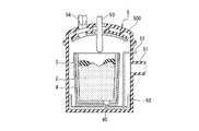
還元工程の後、真空脱ガス装置5にて溶鋼である溶湯2に、真空脱ガス処理を施す脱ガス工程を行う(S104)。真空脱ガス装置5は、VOD方式の脱ガス装置であり、取鍋4に収容された溶湯2を、減圧下で攪拌処理することで脱ガス処理を施す。真空脱ガス装置5は、真空槽50と、排気管51と、攪拌ガス供給経路52と、上吹きランス53と、供給口54とを有する。真空槽50は、取鍋4を内部に収容可能な容器であり、取鍋4を内部に出し入れ可能なように着脱式の上蓋500を有する。排気管51は、真空槽50の側面に設けられ、不図示の排気装置に接続される。攪拌ガス供給経路52は、真空槽50の外部から内部に配され、真空槽50の内部側の先端が取鍋4の吹き込み口40に接続される。また、攪拌ガス供給経路52は、真空槽50の内部側の先端が不図示の攪拌ガス供給装置に接続され、攪拌ガス供給装置から供給されるアルゴンガスなどの攪拌ガスを取鍋4の吹き込み口40に供給する。上吹きランス53は、上蓋500の中央に挿通して、鉛直方向(図3の上下方向)に昇降可能に構成される。また、上吹きランス53は、下端にノズル孔が形成され、不図示の供給設備から供給される少なくとも酸素を含む酸化性ガスをノズル孔から、取鍋4に収容された溶湯2に酸化性ガスを噴射する。供給口54は、上蓋500に形成され、石灰を含む媒溶剤や合金鉄等の各種副原料を貯蔵する不図示の複数の炉上ホッパーに接続され、各炉上ホッパーから切り出される副原料を取鍋4に収容された溶湯2へと添加する投入口である。 After the reduction process, a degassing process is performed in which vacuum degassing is performed on the
脱ガス工程では、取鍋4を真空槽50内に収容した後、吹き込み口40から攪拌ガスを吹き込むことで溶湯2を攪拌させながら、排気装置を用いて排気管51から排気を行い、真空槽50内を減圧することで真空脱ガス処理を行う。このような真空脱ガス処理をすることで、溶湯2中のガス成分(窒素や水素等)の除去や、溶湯2の成分の均一化、溶湯2の介在物等の除去、溶湯2の温度の調整等を行う。また、脱ガス工程では、真空脱ガス処理を行う際に、真空脱ガス処理の処理前あるいは処理途中の溶湯2の成分に応じて、目標とする成分範囲になるように、成分調整用の副原料を、供給口54を通じて溶湯2に添加する。この際、真空脱ガス処理前の溶湯2のマンガン濃度が目標濃度よりも低い場合には、金属マンガンや高炭素フェロマンガン、低炭素フェロマンガン等のマンガン源を、成分調整のために必要な量だけ溶湯2に添加する。また、Al、Ni、Cr、Cu、Nb、Ti、V、Ca、B等の成分調整が必要な場合には、各成分を含有する副原料を溶湯2に添加する。さらに、脱硫等を目的に、CaO含有物質やMgO含有物質、アルミニウム含有物質、Al2O3含有物質、SiO2含有物質等の、スラグ3の組成の調整や脱硫反応の促進に用いられる副原料を溶湯2に添加してもよい。In the degassing step, after the
また、脱ガス工程では、下記(4)式で示される攪拌動力ε(W/t)が、300W/t以上、1300W/t以下となる条件で溶湯2を攪拌することが好ましい。攪拌動力εが300W/t未満となる場合、攪拌力が小さくなるため、脱窒処理や脱水素処理に時間を要し、真空脱ガス処理の処理時間が延長するため好ましくない。また、攪拌動力εが1300W/tよりも大きい場合、溶湯2へのスラグ3の巻き込み量が多くなり、スラグ系介在物に起因した不良率が増加するため好ましくない。なお、(4)式において、Qnは攪拌ガスの流量(Nm3/min)、Tlは溶湯2の温度(K)、Wmは溶湯2の重量(t)、ρlは溶湯2の密度(kg/m3)、hは取鍋4内の溶湯2の深さである湯面高さ(m)、P1は雰囲気圧力(Torr)、ηはエネルギー伝達効率(−)、Tnは攪拌ガスの温度(K)をそれぞれ示す。また、1Torrは(101325/760)Paである。In the degassing step, it is preferable to stir the
さらに、脱ガス工程では、溶湯2の温度が脱ガス工程終了後の目標とする温度よりも低い場合には、真空脱ガス処理中に溶湯2の温度を上げる昇温処理を行ってもよい。昇温処理では、供給口54から溶湯2にアルミニウムを添加した後、上吹きランス53から酸素を含有した酸化性ガスを溶湯2に噴射する。これにより、溶湯2内のアルミニウムと、酸化性ガスの酸素とが反応することで、溶湯2の温度を上昇させることができる。なお、昇温処理では、(5)式及び(6)式から計算される、上吹きランス53から噴射される酸化性ガスの噴流の動圧P(kPa)を、10kPa以上、50kPa以下となるように制御することが好ましい。動圧Pを上記範囲に制御することで、溶湯2からのマンガンの蒸発を最低限に抑えながらも、効率よく溶湯2を昇熱させることができる。なお、(5)式において、ρgは酸化性ガスの密度(kg/Nm3)、Uは上吹きランス53のノズルから噴出される酸化性ガスのノズル先端での流速(m/sec)をそれぞれ示す。また、(6)式において、Fは酸化性ガスの流量(Nm3/h)、Sは上吹きランス53のノズルの断面積(m2)を示す。Furthermore, in the degassing step, when the temperature of the
脱ガス工程を経ることで、目標とする所定の成分濃度の溶鋼が溶製される。なお、脱ガス工程の後は、溶製された溶鋼を連続鋳造することで、スラブ等の所定の形状の高マンガン鋼の鋳片が製造される。 Through the degassing process, molten steel having a target predetermined component concentration is melted. In addition, after the degassing step, a molten slab or the like is continuously cast to produce a high-manganese steel slab having a predetermined shape such as a slab.
<変形例>
以上で、特定の実施形態を参照して本発明を説明したが、これら説明によって発明を限定することを意図するものではない。本発明の説明を参照することにより、当業者には、開示された実施形態とともに種々の変形例を含む本発明の別の実施形態も明らかである。従って、特許請求の範囲に記載された発明の実施形態には、本明細書に記載したこれらの変形例を単独または組み合わせて含む実施形態も網羅すると解すべきである。<Modification>
Although the present invention has been described above with reference to specific embodiments, it is not intended that the present invention be limited by these descriptions. Other embodiments of the present invention, including various modifications, as well as the disclosed embodiments, will be apparent to those of ordinary skill in the art by reference to the description of the present invention. Therefore, it is to be understood that the embodiments of the invention described in the claims also encompass the embodiments including the variants described above alone or in combination.
例えば、上記実施形態では、真空脱ガス装置5がVOD方式の精錬装置としたが、本発明はかかる例に限定されない。例えば、真空脱ガス装置5は、RH方式の脱ガス装置やDH方式の脱ガス装置であってもよい。なお、真空脱ガス装置がRH方式の脱ガス装置である場合、マンガンの蒸発を抑えるため、真空槽の槽内空間圧力が50Torr〜100Torrとなる条件において、下記(7)式で示される溶鋼の還流量Q(t/min)を150t/min以上、200t/min以下とすることが好ましい。なお、溶鋼の脱窒素や脱水素が必要な場合には、50Torr未満の槽内空間圧力で処理を行ってもよいが、脱窒素及び脱水素後は50Torr以上100Torr以下の槽内空間圧力で処理を行うことが好ましい。(7)式において、Kは定数、Gは浸漬管から吹き込む環流用の吹込みガスの流量(NL/min)、Dは浸漬管の内径(m)、P2は外部圧力(Torr)、P3は真空槽の槽内空間圧力(Torr)をそれぞれ示す。For example, in the above embodiment, the
また、上記実施形態では、転炉1で製造された溶鋼である溶湯2のみを、真空脱ガス装置5で処理する溶湯2として用いるとしたが、本発明はかかる例に限定されない。例えば、転炉1で製造された溶鋼に、別の精錬炉で溶製した溶鋼を合わせた合わせ湯を、真空脱ガス装置5で処理する溶湯2として用いてもよい。この場合、別の精錬炉で溶製した溶鋼のマンガン濃度を高くすることで、転炉1で製造される溶鋼のマンガン濃度を低くすることができる。 Moreover, in the said embodiment, although only the
さらに、上記実施形態では、還元工程には、マンガン源及びシリコン源を添加した後、複数の底吹きノズル12から攪拌ガスを吹き込んで、所定の時間、溶湯2を攪拌させるとしたが、本発明はかかる例に限定されない。還元工程では、撹拌ガスの吹き込みに加えて、上吹きランス11からの酸化性ガスを噴射してもよい。特に、溶湯2の温度を上昇させる必要がある場合には、酸化性ガスによる酸化反応によって昇熱処理を行ってもよい。 Furthermore, in the above embodiment, after the manganese source and the silicon source are added in the reduction step, the stirring gas is blown in from the plurality of
さらに、上記実施形態では、脱炭処理の前に溶銑に脱燐処理を施すとしたが、本発明はかかる例に限定されない。例えば、脱炭処理の前に、脱燐処理に加えて、溶銑中の硫黄濃度を低減する脱硫処理が行われてもよい。脱硫処理は、設備構成に応じて、脱燐処理の前あるいは脱燐処理の後に行われてもよい。
さらに、上記実施形態では、溶銑搬送容器に収容された溶銑に対して脱燐処理を施すとしたが、本発明はかかる例に限定されない。脱燐処理は、例えば、転炉型精錬炉に収容された溶銑に対して、上吹きランスから酸化性ガスを噴射することで処理を行う方法であってもよい。Furthermore, in the above-described embodiment, the hot metal is subjected to the dephosphorization treatment before the decarburization treatment, but the present invention is not limited to this example. For example, before the decarburization treatment, in addition to the dephosphorization treatment, a desulfurization treatment for reducing the sulfur concentration in the hot metal may be performed. The desulfurization process may be performed before the dephosphorization process or after the dephosphorization process depending on the equipment configuration.
Furthermore, in the above-described embodiment, the molten metal contained in the molten metal conveyance container is subjected to the dephosphorizing treatment, but the present invention is not limited to this example. The dephosphorization treatment may be carried out, for example, by injecting an oxidizing gas from a top blowing lance into the hot metal stored in the converter-type smelting furnace.
<実施形態の効果>
(1)本発明の一態様に係る高マンガン鋼の溶製方法は、マンガンを5質量%以上含有する鋼を溶製する際に、転炉1にて、溶銑(溶湯2)に脱炭処理を施すことで、溶銑を炭素濃度の低い溶鋼(溶湯2)とする脱炭工程(ステップS100)と、脱炭工程の後、転炉1に収容された溶鋼に、マンガン源及びシリコン源を添加することで、溶鋼を還元処理する還元工程(ステップS102)と、還元工程の後、真空脱ガス装置5にて、溶鋼に真空脱ガス処理を行う脱ガス工程(ステップS104)と、を備え、還元工程では、目標とする鋼のマンガン濃度に応じてマンガン源を添加し、(1)式を満たすようにシリコン源を添加する。<Effect of the embodiment>
(1) The method for melting high manganese steel according to one aspect of the present invention is to decarburize hot metal (molten metal 2) in converter 1 when melting steel containing 5 mass% or more of manganese. By adding a manganese source and a silicon source to the molten steel housed in the converter 1 after the decarburization step (step S100) in which the molten iron has a low carbon concentration (molten metal 2) and the decarburization step Thus, a reduction process (Step S102) for reducing the molten steel, and a degassing process (Step S104) for performing a vacuum degassing process on the molten steel in the
上記(1)の構成によれば、(2)式の還元反応を促進させることができるため、添加されたマンガン源中のマンガンが溶湯2中に歩留り易くなる。また、マンガン源の添加を転炉1内で行うため、マンガン源の添加による熱ロス(溶湯2の温度の低下)を抑えることができる。さらに、マンガン源の添加後に、転炉1内で溶湯2を昇熱処理することができるため、効率よく昇熱処理を行うことができる。さらに、還元反応の促進に十分な量以上の過剰なシリコン源の添加を抑えることができ、脱ガス工程において脱シリコン処理をする必要がなくなるため、短い処理時間で効率よく脱ガス処理を行うことができる。脱ガス処理時間が長くなると、処理に係るコストが増大することに加え、生産能率の低下することとなる。つまり、上記(1)の構成によれば、マンガンを5質量%以上含む高マンガン鋼を溶製するに際に、高いマンガン歩留りを得ることができ、高効率で高マンガン鋼を溶製することができる。 According to the configuration of the above (1), the reduction reaction of the formula (2) can be promoted, so that the manganese in the added manganese source is easily retained in the
(2)上記(1)の構成において、真空脱ガス装置5として、溶鋼を収容する取鍋の底から攪拌ガスを吹き込むことで溶鋼を攪拌する装置を用い、脱ガス工程では、(4)式で示される攪拌動力εが、300W/t以上、1300W/t以下となる条件で、溶鋼を攪拌しながら真空脱ガス処理を行う。
上記(2)の構成によれば、脱窒処理や脱水素処理に要する時間を短くすることができ、さらに溶湯2へのスラグ3の巻き込みを抑えることができる。このため、真空脱ガス処理の処理時間を短くするができる。(2) In the configuration of the above (1), as the
According to the configuration of (2), the time required for the denitrification treatment and the dehydrogenation treatment can be shortened, and further, the inclusion of the
次に、本発明者らが行った実施例1について説明する。実施例1では、高炉から出銑された溶銑に対して、脱珪処理及び脱燐処理の溶銑予備処理を施し、燐濃度を0.010質量%とした。この溶銑に対して、上記実施形態と同様に、脱炭工程、還元工程及び脱ガス工程を行うことで、マンガン濃度が5質量%以上の高マンガン鋼を溶製した。なお、溶製された高マンガン鋼の成分は、炭素濃度:0.145質量%以上0.155質量%以下、マンガン濃度:24質量%以上25質量%以下、シリコン濃度:0.1質量%以上0.2質量%以下、硫黄濃度:0.002質量%以下、窒素濃度:100ppm以下、水素濃度:5ppm以下であった。 Next, Example 1 performed by the present inventors will be described. In Example 1, the hot metal discharged from the blast furnace was subjected to hot metal pretreatment of desiliconization treatment and dephosphorization treatment, so that the phosphorus concentration was 0.010% by mass. Similar to the above embodiment, a high manganese steel having a manganese concentration of 5% by mass or more was melted by performing a decarburization process, a reduction process, and a degassing process on the hot metal. The components of the molten high manganese steel are as follows: carbon concentration: 0.145 mass% to 0.155 mass%, manganese concentration: 24 mass% to 25 mass%, silicon concentration: 0.1 mass% or more It was 0.2 mass% or less, sulfur concentration: 0.002 mass% or less, nitrogen concentration: 100 ppm or less, and hydrogen concentration: 5 ppm or less.
脱炭工程では、上記実施形態と同様に、溶銑予備処理を施した溶銑である溶湯2に脱炭処理を施し、炭素濃度が0.05質量%になるまで脱炭吹錬を施し溶鋼とした。
還元工程では、脱炭処理を施した溶鋼である溶湯2に、高炭素フェロマンガンと金属マンガンとをマンガン源として添加し、フェロシリコンをシリコン源として添加した。そして、攪拌ガスで溶湯2を攪拌させながら、さらに上吹きランス11からの送酸を継続して行い還元処理を施すことで、マンガン源を溶解させ、溶湯2のマンガン濃度を上昇させた。シリコン源の添加量は、(1)式を満たすものとした。また、還元工程では、マンガン源と共に、石灰を添加した。還元処理終了時の溶湯2のマンガン濃度は、およそ24質量%であった。さらに、還元工程では、転炉1から取鍋4へ溶湯2を移注(出鋼)する際、出鋼される溶湯2に対して、金属アルミニウムを溶鋼1トン当たりに約0.8kg添加した。In the decarburization step, as in the above-described embodiment, the
In the reduction step, high-carbon ferromanganese and metal manganese were added as a manganese source to
脱ガス工程では、還元工程を経た150トンの溶鋼である溶湯2に対して、上記実施形態と同様に、VOD方式の真空脱ガス装置5を用いて脱ガス処理を行った。脱ガス工程では、取鍋4の吹き込み口40から、2000Nl/minの流量のArガスを溶湯2に吹き込み攪拌させながら、真空槽50の槽内空間圧力を2Torrにして脱ガス処理を行った。また、脱ガス工程では、脱ガス処理中に、溶湯2に金属マンガン及び高炭素フェロマンガンを添加し成分調整を行った。 In the degassing step, the degassing process was performed on the
また、実施例1では、比較として、還元工程においてシリコン源の添加量が(1)式を満たさない条件でも高マンガン鋼の溶製を行った(比較例1)。なお、比較例1では、還元工程におけるシリコン源の添加量以外の条件については、実施例1と同様とした。
表1に実施例1の結果として、還元工程におけるシリコン源の添加量、Mn歩留り、出鋼時の溶湯2のシリコン濃度及び脱ガス工程における脱ガス処理に要した時間を示す。なお、表1において、0.013×WMn×xMn/xSiは(1)式に示す範囲の下限値、0.150×WMn×xMn/xSiは(1)式に示す範囲の上限値をそれぞれ示す。表1に示すように、実施例1では、シリコン源の添加量WSiが(1)式の範囲内となる実施例1−1〜1−6の6条件、及びシリコン源の添加量WSiが(1)式の範囲外となる比較例1−1〜1−4の4条件の計10条件で高マンガン鋼を溶製した。また、表1におけるMn歩留りは、還元工程において用いられたマンガン源に含まれるマンガンが溶湯2にどれだけ添加されたか、つまり、マンガン源に含まれるマンガン分が、還元工程前後での溶湯2のマンガン濃度の増加にどれだけ寄与したかを示すものである。Further, in Example 1, as a comparison, the high manganese steel was melted even under the condition that the addition amount of the silicon source did not satisfy the expression (1) in the reduction step (Comparative Example 1). In Comparative Example 1, the conditions other than the addition amount of the silicon source in the reduction step were the same as those in Example 1.
Table 1 shows the amount of silicon source added in the reduction step, the Mn yield, the silicon concentration of the
表1に示すように、比較例1−1,1−2の条件では、他の条件に比べてマンガン歩留りが46%以下と低位となった。これは、シリコン源の添加量が少なかったために、(2)式で示されるスラグ3の還元反応が十分に進行しなかったことが原因であると考えられる。比較例1−1,1−2では、Mn歩留りが低かったため、脱ガス工程においてシリコン源を添加して還元処理を行い、その後成分及び温度の調整を行う必要があり、脱ガス工程に要した時間が実施例1−1〜1−6に比べ長くなった。 As shown in Table 1, under the conditions of Comparative Examples 1-1 and 1-2, the manganese yield was as low as 46% or less as compared with other conditions. This is considered to be caused by the fact that the reduction reaction of the
また、比較例1−3,1−4の条件では、マンガン歩留りは高くなったものの、出鋼時のシリコン濃度が規格上限値である0.20質量%を超えてしまった。これは、(2)式で示されるスラグ3の還元反応や(3)式で示される脱硫反応で消費される量以上のシリコンが溶湯2に供給されたためであると考えられる。比較例1−3,1−4では、出鋼時のシリコン濃度が高かったため、脱ガス処理工程において脱シリコン処理を行う必要があり、脱ガス工程に要した時間が実施例1−1〜1−6に比べ長くなった。なお、脱シリコン処理では、上吹きランス53から酸化性ガスを溶湯2に噴射することで、溶湯2に含まれるシリコンが酸化除去される。
一方、実施例1−1〜1−6の条件では、還元工程において高いマンガン歩留りを得られ、さらに必要以上にシリコン源が添加されなかったことで出鋼時のシリコン濃度を低くすることができた。このため、脱ガス工程に要する時間を短くすることができた。Further, under the conditions of Comparative Examples 1-3 and 1-4, the manganese yield was high, but the silicon concentration at the time of steel output exceeded the standard upper limit of 0.20% by mass. This is considered to be because more silicon than the amount consumed by the reduction reaction of the
On the other hand, under the conditions of Examples 1-1 to 1-6, a high manganese yield can be obtained in the reduction process, and the silicon concentration at the time of steel output can be lowered by not adding a silicon source more than necessary. It was. Therefore, the time required for the degassing step could be shortened.
次に、本発明者らが行った実施例2について説明する。実施例2では、実施例1−4と同様な溶製方法で、脱ガス工程での攪拌動力εを変更した複数の条件で高マンガン鋼の溶製を行った。なお、溶製された高マンガン鋼の成分は、炭素濃度:0.145質量%以上0.155質量%以下、マンガン濃度:24質量%以上25質量%以下、シリコン濃度:0.1質量%以上0.2質量%以下、硫黄濃度:0.002質量%以下、窒素濃度:100ppm以下、水素濃度:5ppm以下であった。 Next, Example 2 performed by the present inventors will be described. In Example 2, high manganese steel was melted under a plurality of conditions in which the stirring power ε in the degassing step was changed by the same melting method as in Example 1-4. The components of the molten high manganese steel are as follows: carbon concentration: 0.145 mass% to 0.155 mass%, manganese concentration: 24 mass% to 25 mass%, silicon concentration: 0.1 mass% or more It was 0.2 mass% or less, sulfur concentration: 0.002 mass% or less, nitrogen concentration: 100 ppm or less, and hydrogen concentration: 5 ppm or less.
具体的には、脱炭工程として、実施例1−4と同様に、転炉1にて溶銑予備処理を施した溶銑である溶湯2に脱炭処理を施し、炭素濃度が0.05質量%になるまで脱炭吹錬を施し溶鋼とした。次いで、還元工程として、実施例1−4と同様に、35kg/tのシリコン源を添加して溶湯2に還元処理を施した。還元処理終了時の溶湯2のマンガン濃度は、およそ24質量%であった。さらに、脱ガス工程として、実施例1−4と同様に、真空脱ガス装置5にて溶湯2に脱ガス処理を施した。脱ガス工程では、取鍋4の吹き込み口40から吹き込むArガスの流量を調整することで、攪拌動力εを任意に変更した複数の条件で脱ガス処理を行った。 Specifically, as in the decarburization step, as in Example 1-4, the decarburization treatment was performed on the
表2に実施例2の結果として、還元工程におけるシリコン源の添加量、Mn歩留り、出鋼時の溶湯2のシリコン濃度、脱ガス工程における攪拌動力及び脱ガス工程における脱ガス処理に要した時間を示す。表2に示すように、実施例2では、脱ガス工程における攪拌動力が異なる実施例2−1〜2−10の10条件で高マンガン鋼を溶製した。なお、実施例1−4における脱ガス工程での攪拌動力εは、実施例2−1に相当する。また、実施例2−1〜2−10において、上記以外の溶製条件については、実施例1−4と同じとした。 Table 2 shows the results of Example 2, adding amount of silicon source in reduction process, Mn yield, silicon concentration of
表2に示すように、攪拌動力εが300W/t以上、1300W/t以下となる実施例2−3〜2−8の条件では、攪拌動力εが300W/t未満となる実施例2−1,2−2や攪拌動力εが1300W/t超となる実施例2−9,2−10に比べ、脱ガス処理に要する時間が短くなることが確認できた。これは、溶湯2に適切な攪拌動力を与えて攪拌を行うことで、真空脱ガス処理での脱水素、脱窒素及び介在物の浮上が促進されたためであると考えられる。 As shown in Table 2, under the conditions of Examples 2-3 to 2-8 in which the stirring power ε is 300 W / t or more and 1300 W / t or less, Example 2-1 in which the stirring power ε is less than 300 W / t. , 2-2 and stirring power ε exceeding 1300 W / t, it was confirmed that the time required for the degassing treatment was shortened compared to Examples 2-9 and 2-10. It is considered that this is because dehydrogenation in the vacuum degassing process, denitrification, and floating of inclusions are promoted by giving a suitable stirring power to the
これに対して、攪拌動力εが300W/t未満となる実施例2−1,2−2の条件では、攪拌が弱かったため、脱水素や脱窒素に時間を要したため、脱ガス処理に要する時間が長くなる結果となった。また、攪拌動力εが1300W/t超となる実施例2−9,2−10の条件では、攪拌が強過ぎたため、溶湯2へのスラグ3の巻き込み量が多くなり、溶湯2中のスラグ系介在物を浮上させるのに時間を要したため、脱ガス処理に要する時間が長くなる結果となった。 On the other hand, under the conditions of Examples 2-1 and 2-2 in which the stirring power ε is less than 300 W / t, since the stirring was weak, it took time for dehydrogenation and denitrification, so the time required for the degassing treatment The result became longer. Further, under the conditions of Examples 2-9 and 2-10 in which the stirring power ε is more than 1300 W / t, since the stirring is too strong, the amount of the
1 転炉
10 炉体
11 上吹きランス
12 底吹きノズル
13 シュート
2 溶湯
3 スラグ
4 取鍋
40 吹き込み口
5 真空脱ガス装置
50 真空槽
51 排気管
52 攪拌ガス供給経路
53 上吹きランス
54 供給口DESCRIPTION OF SYMBOLS 1
Claims (2)
Translated fromJapanese転炉にて、溶銑に脱炭処理を施すことで、前記溶銑を炭素濃度の低い溶鋼とする脱炭工程と、
該脱炭工程の後、前記転炉に収容された前記溶鋼に、マンガン源及びシリコン源を添加することで、前記溶鋼を還元処理する還元工程と、
前記還元工程の後、真空脱ガス装置にて、前記溶鋼に真空脱ガス処理を行う脱ガス工程と、
を備え、
前記還元工程では、前記マンガン源の添加量に応じて、(1)式を満たすように前記シリコン源を添加することを特徴とする高マンガン鋼の溶製方法。
xSi:シリコン源中のシリコン濃度(質量%)
WMn:マンガン源の添加量(kg/t)
WSi:シリコン源の添加量(kg/t)When melting steel containing 5 mass% or more of manganese,
In the converter, by decarburizing the hot metal, the decarburization step to make the hot metal a molten steel with a low carbon concentration,
A reduction step of reducing the molten steel by adding a manganese source and a silicon source to the molten steel accommodated in the converter after the decarburizing step;
A degassing step of subjecting the molten steel to a vacuum degassing treatment with a vacuum degassing apparatus after the reduction step;
Equipped with
In the reduction step, the silicon source is added to satisfy the formula (1) in accordance with the amount of addition of the manganese source, and the method for producing high manganese steel according to the present invention.
xSi : Silicon concentration in silicon source (mass%)
WMn : Amount of manganese source added (kg / t)
WSi : Addition amount of silicon source (kg / t)
前記脱ガス工程では、(4)式で示される攪拌動力εが、300W/t以上、1300W/t以下となる条件で、前記溶鋼を攪拌しながら真空脱ガス処理を行うことを特徴とする請求項1に記載の高マンガン鋼の溶製方法。
Tl:溶鋼の温度(K)
Wm:溶鋼の重量(t)
ρl:溶鋼の密度(kg/m3)
h:湯面高さ(m)
P2:雰囲気圧力(Torr)
η:エネルギー伝達効率(−)
Tn:攪拌ガスの温度(K)As the vacuum degassing apparatus, an apparatus for stirring the molten steel by blowing a stirring gas from the bottom of a ladle containing the molten steel is used.
In the degassing step, a vacuum degassing process is performed while stirring the molten steel under a condition that the stirring power ε represented by the formula (4) is 300 W / t or more and 1300 W / t or less. Item 2. A method for melting high manganese steel according to Item 1.
Tl : Temperature of molten steel (K)
Wm : Weight of molten steel (t)
ρl : Density of molten steel (kg / m3 )
h: Hot water surface height (m)
P2 : Atmospheric pressure (Torr)
η: Energy transfer efficiency (−)
Tn : Temperature of stirring gas (K)
Applications Claiming Priority (3)
| Application Number | Priority Date | Filing Date | Title |
|---|---|---|---|
| JP2017103666 | 2017-05-25 | ||
| JP2017103666 | 2017-05-25 | ||
| PCT/JP2018/019526WO2018216660A1 (en) | 2017-05-25 | 2018-05-21 | Method for manufacturing high manganese steel ingot |
Publications (2)
| Publication Number | Publication Date |
|---|---|
| JPWO2018216660A1 JPWO2018216660A1 (en) | 2019-06-27 |
| JP6551626B2true JP6551626B2 (en) | 2019-07-31 |
Family
ID=64396816
Family Applications (1)
| Application Number | Title | Priority Date | Filing Date |
|---|---|---|---|
| JP2019506740AActiveJP6551626B2 (en) | 2017-05-25 | 2018-05-21 | Method of melting high manganese steel |
Country Status (6)
| Country | Link |
|---|---|
| EP (1) | EP3633051B1 (en) |
| JP (1) | JP6551626B2 (en) |
| KR (1) | KR102315999B1 (en) |
| CN (1) | CN110621793A (en) |
| TW (1) | TWI685577B (en) |
| WO (1) | WO2018216660A1 (en) |
Families Citing this family (4)
| Publication number | Priority date | Publication date | Assignee | Title |
|---|---|---|---|---|
| CN111621621B (en)* | 2020-05-12 | 2022-03-22 | 首钢集团有限公司 | A kind of control method of Mn in molten steel in RH vacuum treatment process |
| JP7235070B2 (en)* | 2021-06-11 | 2023-03-08 | Jfeスチール株式会社 | Method for secondary refining of molten steel and method for manufacturing steel |
| JP7480751B2 (en)* | 2021-06-11 | 2024-05-10 | Jfeスチール株式会社 | METHOD FOR DENITRATION OF MOLTEN STEEL AND METHOD FOR PRODUCING STEEL |
| CN115478222B (en)* | 2022-09-26 | 2023-08-18 | 河南中原特钢装备制造有限公司 | Nonmagnetic stainless steel with high purity and corrosion resistance and smelting method thereof |
Family Cites Families (18)
| Publication number | Priority date | Publication date | Assignee | Title |
|---|---|---|---|---|
| JPH01225715A (en)* | 1988-03-03 | 1989-09-08 | Nkk Corp | Manufacturing method of high manganese steel |
| JPH01301815A (en)* | 1988-05-30 | 1989-12-06 | Sumitomo Metal Ind Ltd | Smelting method of low carbon steel |
| JP2722899B2 (en) | 1991-11-01 | 1998-03-09 | 住友金属工業株式会社 | Decarburization refining method for high Mn steel |
| CA2166097C (en)* | 1993-06-30 | 2002-01-15 | Masataka Yano | Process for producing steel by converter |
| JP4534734B2 (en) | 2004-11-29 | 2010-09-01 | Jfeスチール株式会社 | Melting method of low carbon high manganese steel |
| UA82962C2 (en)* | 2005-12-02 | 2008-05-26 | Sms Demag Ag | Method and smelting unit for obtaining steel with high manganese and low carbon content |
| CN100434556C (en)* | 2006-09-26 | 2008-11-19 | 山西太钢不锈钢股份有限公司 | Method for adding Mn into high Mn content stainless steel in smelting process |
| JP4911298B2 (en)* | 2006-10-17 | 2012-04-04 | 大同特殊鋼株式会社 | Manufacturing method of high Mn steel |
| TW200920859A (en)* | 2007-11-02 | 2009-05-16 | Walsin Lihwa Corp | Steelmaking method of separately refining manganese and chromium for high manganese stainless steel |
| JP5509876B2 (en)* | 2010-01-26 | 2014-06-04 | Jfeスチール株式会社 | Melting method of low carbon high manganese steel |
| CN102168160B (en)* | 2011-03-08 | 2013-04-17 | 武汉钢铁(集团)公司 | Converter steelmaking technology for directly reducing-alloying manganese ore |
| JP5861825B2 (en) | 2011-11-29 | 2016-02-16 | Jfeスチール株式会社 | Melting method of low carbon high manganese steel |
| JP5408369B2 (en)* | 2012-01-19 | 2014-02-05 | Jfeスチール株式会社 | Hot metal pretreatment method |
| CN102965584B (en)* | 2012-12-17 | 2014-11-05 | 山西太钢不锈钢股份有限公司 | High-nitrogen high-manganese stainless steel and smelting method thereof |
| AU2013385931B2 (en)* | 2013-04-11 | 2017-04-06 | Posco | Manganese-containing molten steel production method, temperature-holding furnace and manganese-containing molten steel production equipment using temperature-holding furnace |
| CN104109736B (en)* | 2014-06-20 | 2018-05-04 | 宝钢不锈钢有限公司 | A kind of method of 304 stainless steel of AOD converter smeltings |
| JP6269550B2 (en)* | 2015-03-30 | 2018-01-31 | Jfeスチール株式会社 | Method for melting high manganese steel |
| CN105483314B (en)* | 2016-01-04 | 2018-04-24 | 首钢总公司 | A kind of control method for improving the residual manganese content of converter terminal |
- 2018
- 2018-05-21EPEP18806216.0Apatent/EP3633051B1/enactiveActive
- 2018-05-21KRKR1020197033815Apatent/KR102315999B1/enactiveActive
- 2018-05-21JPJP2019506740Apatent/JP6551626B2/enactiveActive
- 2018-05-21CNCN201880032038.3Apatent/CN110621793A/enactivePending
- 2018-05-21WOPCT/JP2018/019526patent/WO2018216660A1/ennot_activeCeased
- 2018-05-24TWTW107117640Apatent/TWI685577B/enactive
Also Published As
| Publication number | Publication date |
|---|---|
| EP3633051B1 (en) | 2021-11-17 |
| EP3633051A4 (en) | 2020-04-08 |
| KR102315999B1 (en) | 2021-10-21 |
| EP3633051A1 (en) | 2020-04-08 |
| CN110621793A (en) | 2019-12-27 |
| JPWO2018216660A1 (en) | 2019-06-27 |
| TWI685577B (en) | 2020-02-21 |
| WO2018216660A1 (en) | 2018-11-29 |
| KR20190142355A (en) | 2019-12-26 |
| TW201900897A (en) | 2019-01-01 |
Similar Documents
| Publication | Publication Date | Title |
|---|---|---|
| US7901482B2 (en) | Removal method of nitrogen in molten steel | |
| JP6551626B2 (en) | Method of melting high manganese steel | |
| JP6343844B2 (en) | Method for refining molten steel in vacuum degassing equipment | |
| JP2011208170A (en) | Method of producing manganese-containing low carbon steel | |
| JP6269550B2 (en) | Method for melting high manganese steel | |
| JP4742740B2 (en) | Method for melting low-sulfur steel | |
| JP5614306B2 (en) | Method for melting manganese-containing low carbon steel | |
| JP4534734B2 (en) | Melting method of low carbon high manganese steel | |
| JPH06240338A (en) | Method for desulfurizing molten steel | |
| JP2776118B2 (en) | Melting method for non-oriented electrical steel sheet | |
| JP2018100427A (en) | Method for producing low sulfur steel | |
| JP4687103B2 (en) | Melting method of low carbon aluminum killed steel | |
| JP7235070B2 (en) | Method for secondary refining of molten steel and method for manufacturing steel | |
| JP4085898B2 (en) | Melting method of low carbon high manganese steel | |
| JP3241910B2 (en) | Manufacturing method of extremely low sulfur steel | |
| JP2008150710A (en) | Melting method of low carbon high manganese steel | |
| JPH11140530A (en) | Manufacturing method of ultra low nitrogen stainless steel | |
| WO2020152945A1 (en) | Method for producing low-carbon ferromanganese | |
| JPH06228626A (en) | Method for reforming slag as pretreatment of desulfurization | |
| JP5621618B2 (en) | Method for melting manganese-containing low carbon steel | |
| JP2009114491A (en) | Method for refining molten steel with RH vacuum degassing equipment | |
| JP3127733B2 (en) | Manufacturing method of ultra clean ultra low carbon steel | |
| JP6028750B2 (en) | Method for melting manganese-containing low carbon steel | |
| JPH11217623A (en) | Refining method of molten steel in reflux vacuum degasser | |
| JPS5952922B2 (en) | Steel manufacturing method |
Legal Events
| Date | Code | Title | Description |
|---|---|---|---|
| A621 | Written request for application examination | Free format text:JAPANESE INTERMEDIATE CODE: A621 Effective date:20190207 | |
| A871 | Explanation of circumstances concerning accelerated examination | Free format text:JAPANESE INTERMEDIATE CODE: A871 Effective date:20190207 | |
| A975 | Report on accelerated examination | Free format text:JAPANESE INTERMEDIATE CODE: A971005 Effective date:20190306 | |
| A131 | Notification of reasons for refusal | Free format text:JAPANESE INTERMEDIATE CODE: A131 Effective date:20190326 | |
| TRDD | Decision of grant or rejection written | ||
| A01 | Written decision to grant a patent or to grant a registration (utility model) | Free format text:JAPANESE INTERMEDIATE CODE: A01 Effective date:20190604 | |
| A61 | First payment of annual fees (during grant procedure) | Free format text:JAPANESE INTERMEDIATE CODE: A61 Effective date:20190617 | |
| R150 | Certificate of patent or registration of utility model | Ref document number:6551626 Country of ref document:JP Free format text:JAPANESE INTERMEDIATE CODE: R150 | |
| R250 | Receipt of annual fees | Free format text:JAPANESE INTERMEDIATE CODE: R250 | |
| R250 | Receipt of annual fees | Free format text:JAPANESE INTERMEDIATE CODE: R250 | |
| R250 | Receipt of annual fees | Free format text:JAPANESE INTERMEDIATE CODE: R250 | |
| R250 | Receipt of annual fees | Free format text:JAPANESE INTERMEDIATE CODE: R250 |