JP6549610B2 - Delivery and deployment system for bifurcated stent grafts - Google Patents
Delivery and deployment system for bifurcated stent graftsDownload PDFInfo
- Publication number
- JP6549610B2 JP6549610B2JP2016560654AJP2016560654AJP6549610B2JP 6549610 B2JP6549610 B2JP 6549610B2JP 2016560654 AJP2016560654 AJP 2016560654AJP 2016560654 AJP2016560654 AJP 2016560654AJP 6549610 B2JP6549610 B2JP 6549610B2
- Authority
- JP
- Japan
- Prior art keywords
- core member
- leg
- stent graft
- sheath
- diameter
- Prior art date
- Legal status (The legal status is an assumption and is not a legal conclusion. Google has not performed a legal analysis and makes no representation as to the accuracy of the status listed.)
- Active
Links
Images


Classifications
- A—HUMAN NECESSITIES
- A61—MEDICAL OR VETERINARY SCIENCE; HYGIENE
- A61F—FILTERS IMPLANTABLE INTO BLOOD VESSELS; PROSTHESES; DEVICES PROVIDING PATENCY TO, OR PREVENTING COLLAPSING OF, TUBULAR STRUCTURES OF THE BODY, e.g. STENTS; ORTHOPAEDIC, NURSING OR CONTRACEPTIVE DEVICES; FOMENTATION; TREATMENT OR PROTECTION OF EYES OR EARS; BANDAGES, DRESSINGS OR ABSORBENT PADS; FIRST-AID KITS
- A61F2/00—Filters implantable into blood vessels; Prostheses, i.e. artificial substitutes or replacements for parts of the body; Appliances for connecting them with the body; Devices providing patency to, or preventing collapsing of, tubular structures of the body, e.g. stents
- A61F2/95—Instruments specially adapted for placement or removal of stents or stent-grafts
- A61F2/954—Instruments specially adapted for placement or removal of stents or stent-grafts for placing stents or stent-grafts in a bifurcation
- A—HUMAN NECESSITIES
- A61—MEDICAL OR VETERINARY SCIENCE; HYGIENE
- A61F—FILTERS IMPLANTABLE INTO BLOOD VESSELS; PROSTHESES; DEVICES PROVIDING PATENCY TO, OR PREVENTING COLLAPSING OF, TUBULAR STRUCTURES OF THE BODY, e.g. STENTS; ORTHOPAEDIC, NURSING OR CONTRACEPTIVE DEVICES; FOMENTATION; TREATMENT OR PROTECTION OF EYES OR EARS; BANDAGES, DRESSINGS OR ABSORBENT PADS; FIRST-AID KITS
- A61F2/00—Filters implantable into blood vessels; Prostheses, i.e. artificial substitutes or replacements for parts of the body; Appliances for connecting them with the body; Devices providing patency to, or preventing collapsing of, tubular structures of the body, e.g. stents
- A61F2/02—Prostheses implantable into the body
- A61F2/04—Hollow or tubular parts of organs, e.g. bladders, tracheae, bronchi or bile ducts
- A61F2/06—Blood vessels
- A61F2/07—Stent-grafts
- A—HUMAN NECESSITIES
- A61—MEDICAL OR VETERINARY SCIENCE; HYGIENE
- A61F—FILTERS IMPLANTABLE INTO BLOOD VESSELS; PROSTHESES; DEVICES PROVIDING PATENCY TO, OR PREVENTING COLLAPSING OF, TUBULAR STRUCTURES OF THE BODY, e.g. STENTS; ORTHOPAEDIC, NURSING OR CONTRACEPTIVE DEVICES; FOMENTATION; TREATMENT OR PROTECTION OF EYES OR EARS; BANDAGES, DRESSINGS OR ABSORBENT PADS; FIRST-AID KITS
- A61F2/00—Filters implantable into blood vessels; Prostheses, i.e. artificial substitutes or replacements for parts of the body; Appliances for connecting them with the body; Devices providing patency to, or preventing collapsing of, tubular structures of the body, e.g. stents
- A61F2/02—Prostheses implantable into the body
- A61F2/04—Hollow or tubular parts of organs, e.g. bladders, tracheae, bronchi or bile ducts
- A61F2/06—Blood vessels
- A61F2002/065—Y-shaped blood vessels
Landscapes
- Health & Medical Sciences (AREA)
- Engineering & Computer Science (AREA)
- Biomedical Technology (AREA)
- Cardiology (AREA)
- Oral & Maxillofacial Surgery (AREA)
- Transplantation (AREA)
- Heart & Thoracic Surgery (AREA)
- Vascular Medicine (AREA)
- Life Sciences & Earth Sciences (AREA)
- Animal Behavior & Ethology (AREA)
- General Health & Medical Sciences (AREA)
- Public Health (AREA)
- Veterinary Medicine (AREA)
- Gastroenterology & Hepatology (AREA)
- Pulmonology (AREA)
- Prostheses (AREA)
- Media Introduction/Drainage Providing Device (AREA)
Description
Translated fromJapanese本開示は、医療装置の展開システムに関する。より詳細には、本開示は、二股ステントグラフトの展開システムに関する。 The present disclosure relates to a medical device deployment system. More particularly, the present disclosure relates to a deployment system for a bifurcated stent graft.
大動脈疾患の腔内処理のために使用する高度な装置、道具、システム、及び方法の必要性がある。具体的には、臨床医の使いやすさを促進しつつ、ますます複雑化している装置の展開形式、例えば操縦、再拘束、多段階の展開、複数の装置の展開に対応することができる展開システムの必要性が残っている。また、送達機構の形状をますます縮小する必要性が残っている。 There is a need for advanced devices, tools, systems and methods for use in intracavitary treatment of aortic disease. Specifically, while promoting the ease of use of clinicians, it is possible to cope with increasingly complex device deployment types, such as steering, re-binding, multistage deployment, and deployment of multiple devices. The need for a system remains. There also remains a need to further reduce the shape of the delivery mechanism.
添付の図面は、本開示の更なる理解を提供するものとして含まれ、本明細書中に取り入れられて一部を構成し、本開示の実施形態を例示し、その記載と共に本開示の原則を説明するのに役立つ。 The accompanying drawings are included to provide a further understanding of the disclosure, and are incorporated into and constitute a part of this specification to illustrate embodiments of the disclosure and, together with the description, to the principles of the disclosure. Help to explain.
様々な実施形態において、医療装置を腔内送達するためのシステムは、主要部(trunk)、第一の脚、及び第二の脚を含み、第一の脚は第二の脚より長い、二股ステントグラフトと;筒状の内面を有する管状壁を有するシースであって、筒状の内面は、ステントグラフトをその中に受容して、ステントグラフトを腔内送達に適する送達形態へと拘束するためのルーメンを画定する、シースと;ルーメンを通って延在する略筒状のコア部材であって、コア部材は、第一の直径を有する第一の部分と、第一の直径より小さい第二の直径を有する第二の部分と、第二の直径より小さい第三の直径を有する第三の部分とを有し、コアは、第一及び第二の部分の間に環状の第一の端面と、第二及び第三の部分の間に環状の第二の端面とを有する、コア部材とを含み、コア部材に対してシースを軸方向に移動させる間、コア部材の第一及び第二の端面はステントグラフトの軸方向に間隔を置いて離れた部分をそれぞれ係合する。 In various embodiments, a system for intraluminal delivery of a medical device includes a trunk, a first leg, and a second leg, the first leg being longer than the second leg, bifurcated A stent graft and a sheath having a tubular wall with a tubular inner surface, the tubular inner surface receiving the stent graft therein for constraining the lumen to a delivery configuration suitable for intraluminal delivery A generally cylindrical core member extending through the lumen, the core member defining a first portion having a first diameter and a second diameter smaller than the first diameter; And a third portion having a third diameter smaller than the second diameter, the core having an annular first end face between the first and second portions; Core member having an annular second end face between second and third parts Include, while moving the sheath relative to the core member in the axial direction, the first and second end surfaces of the core member respectively engage the portion apart at intervals in the axial direction of the stent graft.
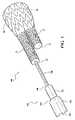
図1〜8を参照すれば、例えば、二股ステントグラフト10を送達するための送達システムを一般に100で示している。示すように、ステントグラフト10は、主要部20と、第一の脚30と、第二の脚40とを含み、第一の脚30は第二の脚40より長い。送達システム100は、管状壁210を有するシース200を含む。管状壁は、外面212と、ルーメン216を画定する反対側の内面214とを含む。ルーメン216は、ステントグラフト10をその中に受容して、ステントグラフト10を脈管処理部位に腔内送達するのに適する送達形態に拘束及び維持するよう構成されている。 With reference to FIGS. 1-8, for example, a delivery system for delivering bifurcated
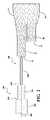
送達システム100は、コア部材300を含む。コア部材300は、長軸302を有し、シース200のルーメン216を通る。コア部材300は、第一の直径を有する第一の部分310を含む。コア部材300は、第一の直径より小さい第二の直径を有する第二の部分320を含む。コア部材300は、第二の直径より小さい第三の直径を有する第三の部分330を含む。
コア部材300は、第一の部分310と第二の部分320との間に環状の第一の端面350を含む。第一の端面350は、実質的にコア部材300の長軸302に対して垂直であることができる。同様に、コア部材300は、第二の部分320と第三の部分330との間に環状の第二の端面360を含む。第二の端面360は、実質的にコア部材300の長軸302に対して垂直であることができる。
組立の間、コア部材300は、図1に示すようにステントグラフト10の第一の脚30を通して、図2及び3に示すように第一の脚30の末端32が第一の端面350に接するまで、挿入することができる。図3の平面「P」で示すように、ステントグラフト10の第二の脚40の末端42は、第二の端面360と軸方向に略整列している。 During assembly, the
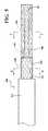
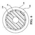
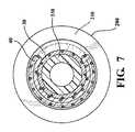
ステントグラフト10を図3に示す構成で取り付け、次にステントグラフト10を、図4〜8に示すようにコア部材300上へと略半径方向に圧縮し、シース200によって送達形態に保持する。図7の(図5の7―7で示す平面に沿う)断面図に最もよく示されているように、第二の脚40は、第三の部分330の外周の一部に沿って圧縮され、他方、第一の脚30は圧縮され、第三の部分330に対して略同軸に整列する。 The
この配置によって、第二の脚40は、コア部材300に沿ってステントグラフト10にカラム強度を加え、コアに対してシース200を軸方向に移動させる間、ステントグラフト10が軸方向につぶれることを防止することを助ける。したがって、ステントグラフト10の展開の間、シース200は、図8の矢印「a」で一般に示す方向に沿って、コア部材300に対して軸方向に移動する。
第一の脚30及び第二の脚40の末端32及び末端42と、第一の端面350及び第二の端面360との間の当接部は、それぞれ、シース10が移動するときのステントグラフト10とシース10との間の摩擦により、ステントグラフト10が軸方向に移動することを妨げる。コア部材300の第三の部分330に沿って圧縮されたステントグラフトの強化されたカラム強度もまた、シース10がコア部材300に対して移動するときのステントグラフト10とシース10の間に摩擦により、ステントグラフトが軸方向につぶれることに抵抗することを助ける。With this arrangement, the
The abutments between the
コア部材300に対するシース10の軸方向の移動は、ステントグラフト10が送達形態から外向きに拡張することを可能にする。任意に、第二のシース又は拘束スリーブを利用して、ステントグラフトの拡張を、送達形態より大きく脈管壁に係合する完全な展開形態よりも小さい中間形態に制限することができる。そのような拘束スリーブに関するさらなる詳細は、例えば、Leopoldらに発行された米国特許第6,352,561号明細書、Thorntonらに発行された米国特許第6,551,350号明細書、及び同時係属米国特許出願公開第2010/0049293号明細書A1(Zukowskiら)に見ることができ、これらの内容は引用によりその全体が本明細書に取り入れられる。 Axial movement of the
ステントグラフト10を完全に展開させると、コア部材300及びシース200は、処理部位及び患者の身体から除去することができる。 Once
本開示の精神又は範囲を逸脱することなく、本開示において様々な変更及び変形を行うことができることは、当業者にとって明らかである。したがって、添付の特許請求の範囲及び均等物の範囲内である限りにおいて、本開示は、本開示の変更及び変形を包含することが意図されている。
以下の項目[1]〜[11]に、本発明の実施形態の例を列記する。
[1]
医療装置を腔内送達するためのシステムであって、前記医療装置は、主要部と、第一の脚と、前記第一の脚より短い第二の脚とを有する二股ステントグラフトを含み、前記システムは:
筒状の内面を有する管状壁を有するシースであって、前記筒状の内面は、前記ステントグラフトをその中に受容して、前記ステントグラフトを腔内送達に適する送達形態へと拘束するためのルーメンを画定する、シースと;
前記ルーメンを通って延在する略筒状のコア部材であって、前記コア部材は、前記第一の脚の末端を係合するための第一の環状面を有し、コアは、少なくとも前記第二の脚の末端が前記シースによって拘束されたまま前記第二の脚の末端を係合するための第二の環状面を有する、コア部材と
を含む、システム。
[2]
前記コア部材は、第一の直径を有する第一の部分と、第二の直径を有する第二の部分とを含み、前記第一の直径は前記第二の直径より大きい、項目1に記載のシステム。
[3]
前記第一の環状面は、前記第一の部分の外面と前記第二の部分の外面との間に延在する、項目2に記載のシステム。
[4]
前記第一の環状面は前記コアの長軸に対して垂直である、項目3に記載のシステム。
[5]
前記コア部材は第三の直径を有する第三の部分を含み、前記第二の直径は前記第三の直径より大きい、項目3に記載のシステム。
[6]
前記第二の環状面は、前記第二の部分の外面と前記第三の部分の外面との間に延在する、項目5に記載のシステム。
[7]
前記第二の環状面は前記コアの長軸に対して垂直である、項目6に記載のシステム。
[8]
前記第一の環状面及び前記第二の環状面が平行である、項目6に記載のシステム。
[9]
前記コア部材の前記第一の部分、前記第二の部分、及び前記第三の部分が同軸に整列している、項目5に記載のシステム。
[10]
前記コア部材の前記第二の部分及び前記第三の部分は、前記二股ステントグラフトの前記第一の脚を通って延在する、項目1に記載のシステム。
[11]
医療用の装置送達システムであって、前記システムは:
近位端と前記近位端の反対側の遠位端との間に延在する二股ステントグラフトであって、前記ステントグラフトは前記近位端と分岐との間に延在する主要部を有し、前記ステントグラフトは前記分岐から遠位に延在する第一の脚及び第二の脚を有し、前記第一の脚は前記ステントグラフトの前記遠位端を画定する末端を有し、前記第二の脚は、前記ステントグラフトの前記分岐と前記遠位端との間の場所で終わる末端を有する、二股ステントグラフトと;
筒状の内面を有する管状壁を有するシースであって、前記筒状の内面は、前記ステントグラフトをその中に受容して、前記ステントグラフトを腔内送達に適する送達形態へと拘束するためのルーメンを画定する、シースと;
前記ルーメンを通って延在し、前記シースと摺動可能に係合する略筒状のコア部材であって、前記コア部材は前記ステントグラフトの前記遠位端を係合するための第一の環状面を有し、コアは、前記コア部材に対して前記シースを移動させる間、少なくとも前記第二の脚の末端が前記シースによって拘束されたまま前記第二の脚の末端を係合する第二の環状面を有し、前記コア部材に沿う前記ステントグラフトの移動を最小化する、コア部材と
を含む、システム。
It will be apparent to those skilled in the art that various changes and modifications can be made in the present disclosure without departing from the spirit or scope of the present disclosure. Thus, it is intended that the present disclosure cover the modifications and variations of the present disclosure as long as they fall within the scope of the appended claims and equivalents.
Examples of the embodiment of the present invention are listed in the following items [1] to [11].
[1]
A system for intraluminal delivery of a medical device, the medical device comprising a bifurcated stent graft having a main part, a first leg and a second leg shorter than the first leg, the system Is:
A sheath having a tubular wall with a tubular inner surface, wherein the tubular inner surface receives a lumen therein for restraining the stent graft into a delivery configuration suitable for intraluminal delivery. Define the sheath;
A generally cylindrical core member extending through the lumen, the core member having a first annular surface for engaging a distal end of the first leg, the core at least A core member having a second annular surface for engaging the distal end of the second leg while the distal end of the second leg is constrained by the sheath
Including the system.
[2]
The core member includes a first portion having a first diameter and a second portion having a second diameter, the first diameter being larger than the second diameter. system.
[3]
The system of claim 2, wherein the first annular surface extends between an outer surface of the first portion and an outer surface of the second portion.
[4]
The system of claim 3, wherein the first annular surface is perpendicular to the longitudinal axis of the core.
[5]
The system according to claim 3, wherein the core member comprises a third portion having a third diameter, the second diameter being greater than the third diameter.
[6]
The system of claim 5, wherein the second annular surface extends between an outer surface of the second portion and an outer surface of the third portion.
[7]
7. A system according to
[8]
7. The system of
[9]
The system of claim 5, wherein the first portion, the second portion, and the third portion of the core member are coaxially aligned.
[10]
The system of claim 1, wherein the second portion and the third portion of the core member extend through the first leg of the bifurcated stent graft.
[11]
A device delivery system for medical use, said system comprising:
A bifurcated stent graft extending between a proximal end and an opposite distal end of the proximal end, the stent graft having a main portion extending between the proximal end and a bifurcation, The stent graft has a first leg and a second leg extending distally from the branch, the first leg having a distal end defining the distal end of the stent graft, the second leg A bifurcated stent-graft, the leg having an end terminating at a location between the bifurcation of the stent-graft and the distal end;
A sheath having a tubular wall with a tubular inner surface, wherein the tubular inner surface receives a lumen therein for restraining the stent graft into a delivery configuration suitable for intraluminal delivery. Define the sheath;
A generally tubular core member extending through the lumen and slidably engaging the sheath, the core member being a first annular member for engaging the distal end of the stent graft A second surface for engaging the distal end of the second leg while at least the distal end of the second leg is restrained by the sheath while moving the sheath relative to the core member; A core member having an annular surface to minimize movement of the stent graft along the core member;
Including the system.
Claims (11)
Translated fromJapanese筒状の内面を有する管状壁を有するシースであって、前記筒状の内面は、前記ステントグラフトをその中に受容して、前記ステントグラフトを腔内送達に適する送達形態へと拘束するためのルーメンを画定する、シースと;
前記ルーメンを通って延在する略筒状のコア部材であって、前記コア部材は、前記第一の脚の末端を係合するための第一の環状面を有し、前記コア部材は、少なくとも前記第二の脚の末端が前記シースによって拘束されたまま前記第二の脚の末端を係合するための第二の環状面を有する、コア部材と
を含む、システム。A system for intraluminal delivery of a medical device, the medical device comprising a bifurcated stent graft having a main part, a first leg and a second leg shorter than the first leg, the system Is:
A sheath having a tubular wall with a tubular inner surface, wherein the tubular inner surface receives a lumen therein for restraining the stent graft into a delivery configuration suitable for intraluminal delivery. Define the sheath;
A generally cylindrical core member extending through the lumen, the core member has a first annular surface for engaging the end of said first leg,said coremember, A core member having a second annular surface for engaging the end of the second leg while at least the end of the second leg is constrained by the sheath.
近位端と前記近位端の反対側の遠位端との間に延在する二股ステントグラフトであって、前記ステントグラフトは前記近位端と分岐との間に延在する主要部を有し、前記ステントグラフトは前記分岐から遠位に延在する第一の脚及び第二の脚を有し、前記第一の脚は前記ステントグラフトの前記遠位端を画定する末端を有し、前記第二の脚は、前記ステントグラフトの前記分岐と前記遠位端との間の場所で終わる末端を有する、二股ステントグラフトと;
筒状の内面を有する管状壁を有するシースであって、前記筒状の内面は、前記ステントグラフトをその中に受容して、前記ステントグラフトを腔内送達に適する送達形態へと拘束するためのルーメンを画定する、シースと;
前記ルーメンを通って延在し、前記シースと摺動可能に係合する略筒状のコア部材であって、前記コア部材は前記ステントグラフトの前記遠位端を係合するための第一の環状面を有し、前記コア部材は、前記コア部材に対して前記シースを移動させる間、少なくとも前記第二の脚の末端が前記シースによって拘束されたまま前記第二の脚の末端を係合する第二の環状面を有し、前記コア部材に沿う前記ステントグラフトの移動を最小化する、コア部材と
を含む、システム。A device delivery system for medical use, said system comprising:
A bifurcated stent graft extending between a proximal end and an opposite distal end of the proximal end, the stent graft having a main portion extending between the proximal end and a bifurcation, The stent graft has a first leg and a second leg extending distally from the branch, the first leg having a distal end defining the distal end of the stent graft, the second leg A bifurcated stent-graft, the leg having an end terminating at a location between the bifurcation of the stent-graft and the distal end;
A sheath having a tubular wall with a tubular inner surface, wherein the tubular inner surface receives a lumen therein for restraining the stent graft into a delivery configuration suitable for intraluminal delivery. Define the sheath;
A generally tubular core member extending through the lumen and slidably engaging the sheath, the core member being a first annular member for engaging the distal end of the stent graft having a surface,said coremember engages between the ends of at least the second leg end the second leg while being restrained by the sheath for moving said sheath relative to said core member A core member having a second annular surface to minimize movement of the stent graft along the core member.
Applications Claiming Priority (5)
| Application Number | Priority Date | Filing Date | Title |
|---|---|---|---|
| US201461975217P | 2014-04-04 | 2014-04-04 | |
| US61/975,217 | 2014-04-04 | ||
| US14/675,368US9974675B2 (en) | 2014-04-04 | 2015-03-31 | Delivery and deployment systems for bifurcated stent grafts |
| US14/675,368 | 2015-03-31 | ||
| PCT/US2015/023874WO2015153754A1 (en) | 2014-04-04 | 2015-04-01 | Delivery and deployment systems for bifurcated stent grafts |
Related Child Applications (1)
| Application Number | Title | Priority Date | Filing Date |
|---|---|---|---|
| JP2019119784ADivisionJP2019195647A (en) | 2014-04-04 | 2019-06-27 | Delivery and deployment system for bifurcated stent graft |
Publications (2)
| Publication Number | Publication Date |
|---|---|
| JP2017509437A JP2017509437A (en) | 2017-04-06 |
| JP6549610B2true JP6549610B2 (en) | 2019-07-24 |
Family
ID=54208738
Family Applications (2)
| Application Number | Title | Priority Date | Filing Date |
|---|---|---|---|
| JP2016560654AActiveJP6549610B2 (en) | 2014-04-04 | 2015-04-01 | Delivery and deployment system for bifurcated stent grafts |
| JP2019119784APendingJP2019195647A (en) | 2014-04-04 | 2019-06-27 | Delivery and deployment system for bifurcated stent graft |
Family Applications After (1)
| Application Number | Title | Priority Date | Filing Date |
|---|---|---|---|
| JP2019119784APendingJP2019195647A (en) | 2014-04-04 | 2019-06-27 | Delivery and deployment system for bifurcated stent graft |
Country Status (9)
| Country | Link |
|---|---|
| US (3) | US9974675B2 (en) |
| EP (2) | EP3125831B1 (en) |
| JP (2) | JP6549610B2 (en) |
| KR (1) | KR102422686B1 (en) |
| CN (2) | CN109620468B (en) |
| AU (1) | AU2015240807B2 (en) |
| CA (1) | CA2944145C (en) |
| ES (1) | ES2924984T3 (en) |
| WO (1) | WO2015153754A1 (en) |
Families Citing this family (3)
| Publication number | Priority date | Publication date | Assignee | Title |
|---|---|---|---|---|
| US9974675B2 (en) | 2014-04-04 | 2018-05-22 | W. L. Gore & Associates, Inc. | Delivery and deployment systems for bifurcated stent grafts |
| US10149777B2 (en)* | 2014-12-18 | 2018-12-11 | Cook Medical Technologies Llc | Orientation marker on pusher for deployment of endoluminal prostheses |
| JP7223703B2 (en) | 2017-03-06 | 2023-02-16 | ディヴェルト・アクチェンゲゼルシャフト | Multi-layered endoluminal prosthesis assembly and manufacturing method |
Family Cites Families (73)
| Publication number | Priority date | Publication date | Assignee | Title |
|---|---|---|---|---|
| US5628783A (en)* | 1991-04-11 | 1997-05-13 | Endovascular Technologies, Inc. | Bifurcated multicapsule intraluminal grafting system and method |
| US5609627A (en)* | 1994-02-09 | 1997-03-11 | Boston Scientific Technology, Inc. | Method for delivering a bifurcated endoluminal prosthesis |
| US7604633B2 (en) | 1996-04-12 | 2009-10-20 | Cytyc Corporation | Moisture transport system for contact electrocoagulation |
| FR2748197A1 (en) | 1996-05-02 | 1997-11-07 | Braun Celsa Sa | Surgical implant positioning device |
| US6770092B2 (en)* | 1996-05-03 | 2004-08-03 | Medinol Ltd. | Method of delivering a bifurcated stent |
| US8211167B2 (en)* | 1999-12-06 | 2012-07-03 | Boston Scientific Scimed, Inc. | Method of using a catheter with attached flexible side sheath |
| US5860998A (en)* | 1996-11-25 | 1999-01-19 | C. R. Bard, Inc. | Deployment device for tubular expandable prosthesis |
| US6551350B1 (en) | 1996-12-23 | 2003-04-22 | Gore Enterprise Holdings, Inc. | Kink resistant bifurcated prosthesis |
| US6352561B1 (en) | 1996-12-23 | 2002-03-05 | W. L. Gore & Associates | Implant deployment apparatus |
| US5928248A (en)* | 1997-02-14 | 1999-07-27 | Biosense, Inc. | Guided deployment of stents |
| US6951572B1 (en)* | 1997-02-20 | 2005-10-04 | Endologix, Inc. | Bifurcated vascular graft and method and apparatus for deploying same |
| US5792144A (en) | 1997-03-31 | 1998-08-11 | Cathco, Inc. | Stent delivery catheter system |
| AUPO700897A0 (en)* | 1997-05-26 | 1997-06-19 | William A Cook Australia Pty Ltd | A method and means of deploying a graft |
| EP1039864B1 (en)* | 1997-11-14 | 2006-12-27 | Boston Scientific Limited | Multi-sheath delivery catheter |
| US6120522A (en)* | 1998-08-27 | 2000-09-19 | Scimed Life Systems, Inc. | Self-expanding stent delivery catheter |
| US6368345B1 (en)* | 1998-09-30 | 2002-04-09 | Edwards Lifesciences Corporation | Methods and apparatus for intraluminal placement of a bifurcated intraluminal garafat |
| US6203550B1 (en) | 1998-09-30 | 2001-03-20 | Medtronic, Inc. | Disposable delivery device for endoluminal prostheses |
| US6241758B1 (en) | 1999-05-28 | 2001-06-05 | Advanced Cardiovascular Systems, Inc. | Self-expanding stent delivery system and method of use |
| EP1400204A1 (en)* | 1999-08-05 | 2004-03-24 | Broncus Technologies, Inc. | Methods and devices for creating collateral channels in the lungs |
| US6689156B1 (en)* | 1999-09-23 | 2004-02-10 | Advanced Stent Technologies, Inc. | Stent range transducers and methods of use |
| EP1372534B1 (en)* | 2001-03-28 | 2006-11-29 | Cook Incorporated | Set of sections for a modular stent graft assembly |
| US6733521B2 (en) | 2001-04-11 | 2004-05-11 | Trivascular, Inc. | Delivery system and method for endovascular graft |
| AUPR847301A0 (en) | 2001-10-26 | 2001-11-15 | Cook Incorporated | Endoluminal prostheses for curved lumens |
| US20100016943A1 (en) | 2001-12-20 | 2010-01-21 | Trivascular2, Inc. | Method of delivering advanced endovascular graft |
| US7147661B2 (en) | 2001-12-20 | 2006-12-12 | Boston Scientific Santa Rosa Corp. | Radially expandable stent |
| GB0203177D0 (en) | 2002-02-11 | 2002-03-27 | Anson Medical Ltd | An improved control mechanism for medical catheters |
| US6911039B2 (en) | 2002-04-23 | 2005-06-28 | Medtronic Vascular, Inc. | Integrated mechanical handle with quick slide mechanism |
| US7550002B2 (en) | 2002-04-30 | 2009-06-23 | Olympus Corporation | Stent delivery device |
| WO2003096935A1 (en) | 2002-05-16 | 2003-11-27 | Cook Incorporated | Flexible barb for anchoring a prosthesis |
| EP1531762B1 (en) | 2002-08-29 | 2010-04-14 | St. Jude Medical, Cardiology Division, Inc. | Implantable devices for controlling the internal circumference of an anatomic orifice or lumen |
| US20040230286A1 (en) | 2003-03-10 | 2004-11-18 | Moore Scott T. | Stent introducer apparatus |
| US8262671B2 (en) | 2003-03-14 | 2012-09-11 | Oscor Inc. | Vascular introducer having hemostatic valve with integral seal |
| US20040267348A1 (en)* | 2003-04-11 | 2004-12-30 | Gunderson Richard C. | Medical device delivery systems |
| US20050050015A1 (en) | 2003-08-29 | 2005-03-03 | Dirk Becker | Generic iViews |
| US7651519B2 (en) | 2003-09-16 | 2010-01-26 | Cook Incorporated | Prosthesis deployment system |
| EP1691719B1 (en) | 2003-10-14 | 2016-09-14 | Cook Medical Technologies LLC | Introducer for an iliac side branch device |
| US8109983B2 (en)* | 2004-08-06 | 2012-02-07 | Boston Scientific Scimed, Inc. | Medical device delivery systems |
| US7740652B2 (en)* | 2005-03-30 | 2010-06-22 | Boston Scientific Scimed, Inc. | Catheter |
| US8608789B2 (en)* | 2005-05-24 | 2013-12-17 | Trireme Medical, Inc. | Delivery system for bifurcation stents |
| US7938851B2 (en) | 2005-06-08 | 2011-05-10 | Xtent, Inc. | Devices and methods for operating and controlling interventional apparatus |
| ATE459312T1 (en) | 2005-08-17 | 2010-03-15 | Bard Inc C R | VARIABLE SPEED STENT DELIVERY SYSTEM |
| US20070050015A1 (en) | 2005-08-25 | 2007-03-01 | Scimed Life Systems, Inc. | Endoluminal prosthesis adapted to deployment in a distorted branched body lumen and method of deploying the same |
| CN102188296A (en)* | 2005-10-20 | 2011-09-21 | 阿普特斯内系统公司 | Devices, systems, and methods for prosthesis delivery and implantation |
| AU2007240703C1 (en)* | 2006-04-19 | 2012-06-14 | Cleveland Clinic Foundation | Twin bifurcated stent graft |
| US9585743B2 (en) | 2006-07-31 | 2017-03-07 | Edwards Lifesciences Cardiaq Llc | Surgical implant devices and methods for their manufacture and use |
| US8257431B2 (en) | 2006-11-01 | 2012-09-04 | Boston Scientific Scimed, Inc. | Multi-furcated ePTFE grafts and stent-graft prostheses and methods of making the same |
| US8052732B2 (en) | 2006-11-14 | 2011-11-08 | Medtronic Vascular, Inc. | Delivery system for stent-graft with anchoring pins |
| EP2089089B1 (en) | 2006-11-30 | 2010-08-04 | William Cook Europe ApS | Pusher sheath and deployment device |
| EP2497520B1 (en)* | 2007-07-18 | 2022-04-13 | Silk Road Medical, Inc. | Systems for establishing retrograde carotid arterial blood flow |
| US8328861B2 (en)* | 2007-11-16 | 2012-12-11 | Trivascular, Inc. | Delivery system and method for bifurcated graft |
| WO2009102441A1 (en) | 2008-02-11 | 2009-08-20 | William A. Cook Australia Pty. Ltd. | Curve forming apparatus and curvable stent graft |
| DE102008012113A1 (en) | 2008-03-02 | 2009-09-03 | Transcatheter Technologies Gmbh | Implant e.g. heart-valve-carrying stent, for e.g. arresting blood vessel, has fiber by which section of implant is reducible according to increasing of implant at extended diameter by unfolding or expansion of diameter with expansion unit |
| US20090259296A1 (en)* | 2008-04-10 | 2009-10-15 | Medtronic Vascular, Inc. | Gate Cannulation Apparatus and Methods |
| US8236040B2 (en)* | 2008-04-11 | 2012-08-07 | Endologix, Inc. | Bifurcated graft deployment systems and methods |
| WO2009148607A1 (en) | 2008-06-04 | 2009-12-10 | Gore Enterprise Holdings, Inc. | Controlled deployable medical device and method of making the same |
| CN102076281B (en)* | 2008-06-30 | 2014-11-05 | 波顿医疗公司 | Systems and methods for abdominal aortic aneurysm |
| EP2520320B1 (en) | 2008-07-01 | 2016-11-02 | Endologix, Inc. | Catheter system |
| GB2464978B (en) | 2008-10-31 | 2010-10-20 | Cook William Europ | Introducer for deploying a stent graft in a curved lumen |
| EP2490629B1 (en) | 2009-10-20 | 2019-05-22 | Cook Medical Technologies, LLC | Rotational controlled deployment device |
| CA2794279A1 (en)* | 2010-03-24 | 2011-09-29 | Advanced Bifurcation Systems, Inc. | Methods and systems for ostial stenting of a bifurcation |
| US20110251664A1 (en) | 2010-04-08 | 2011-10-13 | Medtronic Vascular, Inc. | Short Legged Bifurcated Stent Graft Distal Capture Element and Method |
| US9265599B2 (en)* | 2011-08-31 | 2016-02-23 | Cleveland Clinic Foundation | Retention system for an endoluminal device |
| US9072624B2 (en)* | 2012-02-23 | 2015-07-07 | Covidien Lp | Luminal stenting |
| US8968384B2 (en) | 2012-04-27 | 2015-03-03 | Medtronic Vascular, Inc. | Circumferentially constraining sutures for a stent-graft |
| US9132025B2 (en) | 2012-06-15 | 2015-09-15 | Trivascular, Inc. | Bifurcated endovascular prosthesis having tethered contralateral leg |
| US9498361B2 (en) | 2012-12-19 | 2016-11-22 | Cook Medical Technologies Llc | Repositionable diameter constraints |
| US10350096B2 (en) | 2012-12-26 | 2019-07-16 | Cook Medical Technologies Llc | Expandable stent-graft system having diameter reducing connectors |
| US9308349B2 (en) | 2013-02-08 | 2016-04-12 | Vention Medical Advanced Components, Inc. | Universal catheter handle |
| US9254204B2 (en) | 2013-03-15 | 2016-02-09 | Cook Medical Technologies Llc | Stents having barbs protected during delivery |
| WO2014182855A1 (en) | 2013-05-07 | 2014-11-13 | St. Jude Medical, Atrial Fibrillation Division, Inc. | Steering actuator for deflectable catheter |
| US9974675B2 (en) | 2014-04-04 | 2018-05-22 | W. L. Gore & Associates, Inc. | Delivery and deployment systems for bifurcated stent grafts |
| EP3284446B1 (en) | 2014-12-04 | 2018-12-19 | Cook Medical Technologies LLC | Delivery device handle assembly for the sequential deployment of a prosthesis |
| CN109069282A (en) | 2016-04-05 | 2018-12-21 | 波顿医疗公司 | Delivery system and application method with guide and distal sheath |
- 2015
- 2015-03-31USUS14/675,368patent/US9974675B2/enactiveActive
- 2015-04-01CNCN201910067082.4Apatent/CN109620468B/enactiveActive
- 2015-04-01ESES15721904Tpatent/ES2924984T3/enactiveActive
- 2015-04-01WOPCT/US2015/023874patent/WO2015153754A1/enactiveApplication Filing
- 2015-04-01CNCN201580017682.XApatent/CN106163451B/enactiveActive
- 2015-04-01CACA2944145Apatent/CA2944145C/enactiveActive
- 2015-04-01JPJP2016560654Apatent/JP6549610B2/enactiveActive
- 2015-04-01AUAU2015240807Apatent/AU2015240807B2/enactiveActive
- 2015-04-01KRKR1020167031011Apatent/KR102422686B1/enactiveActive
- 2015-04-01EPEP15721904.9Apatent/EP3125831B1/enactiveActive
- 2015-04-01EPEP22171483.5Apatent/EP4074289A1/enactivePending
- 2018
- 2018-05-18USUS15/983,186patent/US11690742B2/enactiveActive
- 2019
- 2019-06-27JPJP2019119784Apatent/JP2019195647A/enactivePending
- 2023
- 2023-05-24USUS18/201,260patent/US20230293326A1/enactivePending
Also Published As
| Publication number | Publication date |
|---|---|
| US20180263800A1 (en) | 2018-09-20 |
| US9974675B2 (en) | 2018-05-22 |
| AU2015240807A1 (en) | 2016-11-17 |
| EP3125831B1 (en) | 2022-06-01 |
| EP3125831A1 (en) | 2017-02-08 |
| US11690742B2 (en) | 2023-07-04 |
| JP2019195647A (en) | 2019-11-14 |
| EP4074289A1 (en) | 2022-10-19 |
| CN109620468A (en) | 2019-04-16 |
| WO2015153754A1 (en) | 2015-10-08 |
| ES2924984T3 (en) | 2022-10-13 |
| CA2944145C (en) | 2019-09-17 |
| KR20160145065A (en) | 2016-12-19 |
| US20230293326A1 (en) | 2023-09-21 |
| AU2015240807B2 (en) | 2018-03-01 |
| CN109620468B (en) | 2021-07-30 |
| JP2017509437A (en) | 2017-04-06 |
| CN106163451A (en) | 2016-11-23 |
| CN106163451B (en) | 2019-02-26 |
| KR102422686B1 (en) | 2022-07-18 |
| CA2944145A1 (en) | 2015-10-08 |
| US20150282967A1 (en) | 2015-10-08 |
Similar Documents
| Publication | Publication Date | Title |
|---|---|---|
| JP5068527B2 (en) | Stent delivery system with improved delivery force distribution | |
| JP2017516520A5 (en) | ||
| EP2670345B1 (en) | Vascular and bodily duct treatment devices | |
| US20200030122A1 (en) | Medical device suitable for location in a body lumen | |
| US20230293326A1 (en) | Delivery and deployment systems for bifurcated stent grafts | |
| CN104042380A (en) | Delivery system for expandable stents | |
| JP2008539011A5 (en) | ||
| WO2001054614A3 (en) | Self-expanding stent with enhanced delivery precision and stent delivery system | |
| JP5988408B2 (en) | Medical device suitable for placement in the body lumen | |
| JP2017536869A5 (en) | ||
| CN105392452A (en) | Delivery device for partially unconstrained endoprosthesis | |
| JP5198258B2 (en) | Endoprosthesis delivery system | |
| JP7295868B2 (en) | Medical tubular body conveying device | |
| US20080125845A1 (en) | Proximal fixing | |
| JP2014503241A5 (en) | ||
| EP2248490A1 (en) | A medical device suitable for location in a body lumen | |
| US9839539B2 (en) | Bow stent | |
| JP2013176485A (en) | Stent | |
| JP2013052041A (en) | Stent delivery catheter |
Legal Events
| Date | Code | Title | Description |
|---|---|---|---|
| A621 | Written request for application examination | Free format text:JAPANESE INTERMEDIATE CODE: A621 Effective date:20180202 | |
| A977 | Report on retrieval | Free format text:JAPANESE INTERMEDIATE CODE: A971007 Effective date:20181206 | |
| A131 | Notification of reasons for refusal | Free format text:JAPANESE INTERMEDIATE CODE: A131 Effective date:20190108 | |
| A601 | Written request for extension of time | Free format text:JAPANESE INTERMEDIATE CODE: A601 Effective date:20190405 | |
| A521 | Request for written amendment filed | Free format text:JAPANESE INTERMEDIATE CODE: A523 Effective date:20190422 | |
| TRDD | Decision of grant or rejection written | ||
| A01 | Written decision to grant a patent or to grant a registration (utility model) | Free format text:JAPANESE INTERMEDIATE CODE: A01 Effective date:20190528 | |
| A61 | First payment of annual fees (during grant procedure) | Free format text:JAPANESE INTERMEDIATE CODE: A61 Effective date:20190627 | |
| R150 | Certificate of patent or registration of utility model | Ref document number:6549610 Country of ref document:JP Free format text:JAPANESE INTERMEDIATE CODE: R150 | |
| R250 | Receipt of annual fees | Free format text:JAPANESE INTERMEDIATE CODE: R250 | |
| R250 | Receipt of annual fees | Free format text:JAPANESE INTERMEDIATE CODE: R250 | |
| R250 | Receipt of annual fees | Free format text:JAPANESE INTERMEDIATE CODE: R250 | |
| R250 | Receipt of annual fees | Free format text:JAPANESE INTERMEDIATE CODE: R250 |