JP6547517B2 - Heat exchanger manufacturing method - Google Patents
Heat exchanger manufacturing methodDownload PDFInfo
- Publication number
- JP6547517B2 JP6547517B2JP2015166410AJP2015166410AJP6547517B2JP 6547517 B2JP6547517 B2JP 6547517B2JP 2015166410 AJP2015166410 AJP 2015166410AJP 2015166410 AJP2015166410 AJP 2015166410AJP 6547517 B2JP6547517 B2JP 6547517B2
- Authority
- JP
- Japan
- Prior art keywords
- heat exchanger
- groove
- manufacturing
- wall
- lid
- Prior art date
- Legal status (The legal status is an assumption and is not a legal conclusion. Google has not performed a legal analysis and makes no representation as to the accuracy of the status listed.)
- Active
Links
Images


Landscapes
- Details Of Heat-Exchange And Heat-Transfer (AREA)
- Heat-Exchange Devices With Radiators And Conduit Assemblies (AREA)
- Pressure Welding/Diffusion-Bonding (AREA)
Description
Translated fromJapanese本発明は、熱交換器の製造方法に関する。 The present invention relates to a method of manufacturing a heat exchanger.
特許文献1には、複数の中空部を備えた熱交換器の製造方法が開示されている。当該熱交換器の製造方法は、複数のピン(フィン)が形成された下壁及び上壁をロウ付けし、冷媒が流れる中空部を形成している。 Patent Document 1 discloses a method of manufacturing a heat exchanger having a plurality of hollow portions. The manufacturing method of the said heat exchanger brazes the lower wall and upper wall in which several pins (fin) were formed, and forms the hollow part into which a refrigerant | coolant flows.
従来技術であると、ロウ付け作業が煩雑になるという問題がある。また、ロウ材を介して接合されるため、熱伝導率が低下するという問題がある。 With the prior art, there is a problem that the brazing operation becomes complicated. In addition, there is a problem that the thermal conductivity is reduced because the bonding is performed through the brazing material.
このような観点から、本発明は、熱伝導率の高い熱交換器を容易に製造することができる熱交換器の製造方法を提供することを課題とする。 From such a point of view, an object of the present invention is to provide a method of manufacturing a heat exchanger capable of easily manufacturing a heat exchanger having high thermal conductivity.
このような課題を解決するために本発明は、対向する一対の外壁部を含んで形成された枠状本体部と、前記外壁部同士を連結し複数体並設された隔壁と、前記一対の外壁部の少なくとも一方の表面に形成された蓋溝と、前記蓋溝の底面に形成された凹溝と、を備えた中空押出形材を成形する押出成形工程と、前記凹溝に熱媒体用管を挿入する挿入工程と、前記蓋溝に蓋板を配置する蓋溝閉塞工程と、前記蓋溝の側壁と前記蓋板の側面との突合せ部に回転する回転ツールを相対移動させて摩擦攪拌接合を施す摩擦攪拌工程と、を含むことを特徴とする。 In order to solve such problems, the present invention provides a frame-shaped main body portion formed to include a pair of opposing outer wall portions, a plurality of partition walls which connect the outer wall portions and are juxtaposed, and the pair An extrusion forming step of forming a hollow extruded section provided with a lid groove formed on at least one surface of the outer wall portion and a concave groove formed on the bottom surface of the lid groove; Friction stirring by relatively moving a rotating tool that rotates to a butt between the side wall of the lid groove and the side surface of the lid plate, inserting the tube, lid lid closing step for placing the lid plate in the lid groove, and And b.
かかる方法によれば、押出成形によって、枠状本体部と隔壁とで構成される複数の中空部を備えた中空押出形材が形成される。これにより、熱交換器を容易に形成することができる。また、ロウ材や接着剤等を介さずに形成できるため、熱伝導率の高い熱交換器を製造することができる。 According to such a method, a hollow extruded section having a plurality of hollow parts constituted by the frame-like main body and the partition wall is formed by extrusion molding. Thereby, the heat exchanger can be easily formed. In addition, since the solder can be formed without using a brazing material, an adhesive, or the like, a heat exchanger having a high thermal conductivity can be manufactured.
また、前記押出成形工程では、前記隔壁に対応する位置に前記凹溝を形成することが好ましい。 In the extrusion molding step, it is preferable to form the recessed groove at a position corresponding to the partition wall.
摩擦攪拌工程を行う際に、回転ツールで中空押出形材及び蓋板を押圧すると中空部が変形するおそれがある。しかし、かかる方法によれば、凹溝に対応する位置に隔壁が形成されているため、摩擦攪拌工程時に作用する押圧力を隔壁で支持することができる。これにより、中空部が変形するのを防ぐことができる。 When the hollow extruded material and the lid plate are pressed by the rotating tool when performing the friction stirring process, the hollow portion may be deformed. However, according to such a method, since the partition wall is formed at the position corresponding to the recessed groove, the pressing force acting at the time of the friction stirring process can be supported by the partition wall. This can prevent the hollow portion from being deformed.
また、前記摩擦攪拌工程では、前記熱媒体用管の周囲に形成された空隙部に、摩擦熱によって流動化させた塑性流動材を流入させることが好ましい。かかる方法によれば、空隙部が塑性流動材で充填されるため水密性及び気密性を高めることができる。 Further, in the friction stirring step, it is preferable that the plastic flow material fluidized by the frictional heat is made to flow into the void portion formed around the heat medium pipe. According to this method, since the void portion is filled with the plastic fluid material, it is possible to improve the water tightness and the air tightness.
また、本発明は、対向する一対の外壁部を含んで形成された枠状本体部と、前記外壁部同士を連結し複数体並設された隔壁と、前記一対の外壁部の少なくとも一方の表面に形成された凹溝と、を備えた中空押出形材を成形する押出成形工程と、前記凹溝に熱媒体用管を挿入する挿入工程と、前記熱媒体用管の上に蓋板を配置する凹溝閉塞工程と、前記凹溝の側壁と前記蓋板の側面との突合せ部に回転する回転ツールを相対移動させて摩擦攪拌接合を施す摩擦攪拌工程と、を含むことを特徴とする。 Further, according to the present invention, at least one surface of a frame-shaped main body formed to include a pair of opposing outer walls, a plurality of partitions juxtaposed by connecting the outer walls, and at least one of the pair of outer walls An extrusion step of forming a hollow extruded section having a recessed groove formed thereon, an insertion step of inserting a heat medium pipe into the recessed groove, and a cover plate disposed on the heat medium pipe And a friction stirring process for relatively moving a rotating tool rotating to a butt between the side wall of the groove and the side surface of the lid plate to apply friction stir welding.
かかる方法によれば、押出成形によって、枠状本体部と隔壁とで構成される複数の中空部を備えた中空押出形材が形成される。これにより、熱交換器を容易に形成することができる。また、ロウ材や接着剤等を介さずに形成できるため、熱伝導率の高い熱交換器を製造することができる。 According to such a method, a hollow extruded section having a plurality of hollow parts constituted by the frame-like main body and the partition wall is formed by extrusion molding. Thereby, the heat exchanger can be easily formed. In addition, since the solder can be formed without using a brazing material, an adhesive, or the like, a heat exchanger having a high thermal conductivity can be manufactured.
また、前記押出成形工程では、前記隔壁に対応する位置に前記凹溝を形成することが好ましい。かかる方法によれば、凹溝に対応する位置に隔壁が形成されているため、摩擦攪拌工程時に作用する押圧力を隔壁で支持することができる。これにより、中空部が変形するのを防ぐことができる。 In the extrusion molding step, it is preferable to form the recessed groove at a position corresponding to the partition wall. According to this method, since the partition wall is formed at the position corresponding to the recessed groove, the pressing force acting at the time of the friction stirring process can be supported by the partition wall. This can prevent the hollow portion from being deformed.
また、前記摩擦攪拌工程では、前記回転ツールのショルダ部の直径を、前記凹溝の幅よりも大きく設定するとともに、前記回転ツールの攪拌ピンを前記蓋板の表面に挿入し、一対の前記突合せ部に対して1パスで摩擦攪拌接合を施すことが好ましい。 Further, in the friction stirring step, the diameter of the shoulder portion of the rotating tool is set larger than the width of the recessed groove, and the stirring pin of the rotating tool is inserted into the surface of the lid plate It is preferable to apply friction stir welding to the part in one pass.
かかる方法によれば、一対の突合せ部を回転ツールで同時に摩擦攪拌するため、作業工程を減らすことができる。 According to this method, since the pair of abutment portions are simultaneously frictioned and stirred by the rotary tool, the number of operation steps can be reduced.
また、前記摩擦攪拌工程では、前記回転ツールのショルダ部の押圧力を前記蓋板を介して前記熱媒体用管に伝達させ、前記凹溝の底面に前記熱媒体用管を押し付けながら摩擦攪拌を行うことが好ましい。 In the friction stirring step, the pressing force of the shoulder portion of the rotary tool is transmitted to the heat medium pipe through the lid plate, and the friction stir is performed while pressing the heat medium pipe against the bottom surface of the recessed groove. It is preferred to do.
かかる方法によれば、凹溝の底面と熱媒体用管とが密接するため、熱伝導率をより高めることができる。また、前記中空押出形材は、アルミニウム又はアルミニウム合金で形成されていることが好ましい。According to this method, the heat conductivity can be further improved because the bottom surface of the recessed groove and the heat medium pipe are in close contact with each other.Preferably, the hollow extruded section is formed of aluminum or an aluminum alloy.
本発明に係る熱交換器の製造方法によれば、熱伝導率が高い熱交換器を容易に製造することができる。 According to the method of manufacturing a heat exchanger according to the present invention, a heat exchanger with high thermal conductivity can be easily manufactured.
[第一実施形態]
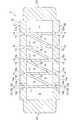
本発明の第一実施形態に係る熱交換器及び熱交換器の製造方法について図面を参照して説明する。図1に示すように、本実施形態に係る熱交換器1は、中空押出形材2と、複数の蓋板3と、複数の熱媒体用管4とで主に構成されている。中空押出形材2の内部には複数の中空部Kが形成されている。熱媒体用管4の端部は、中空押出形材2の側方から露出している。熱交換器1は、熱媒体用管4内を流れる流体(液体又は気体)と、中空部Kを流れる流体とで熱交換を行う機器である。First Embodiment
A heat exchanger and a method of manufacturing the heat exchanger according to a first embodiment of the present invention will be described with reference to the drawings. As shown in FIG. 1, the heat exchanger 1 according to the present embodiment is mainly configured by a hollow extruded
図2に示すように、熱媒体用管4は、蓋板3によって中空押出形材2の内部に埋設されている。中空押出形材2と蓋板3との突合せ部は摩擦攪拌によって接合されている。つまり、中空押出形材2と蓋板3との各突合せ部には塑性化領域W1,W2が形成されている。 As shown in FIG. 2, the
次に、本実施形態に係る熱交換器の製造方法について説明する。本実施形態に係る熱交換器の製造方法は、押出成形工程と、挿入工程と、蓋溝閉塞工程と、摩擦攪拌工程とを行う。なお、下記の説明における「表面」とは、「裏面」の反対側の面を意味する。 Next, a method of manufacturing the heat exchanger according to the present embodiment will be described. The method of manufacturing a heat exchanger according to the present embodiment performs an extrusion molding step, an insertion step, a lid groove closing step, and a friction stirring step. In addition, the "surface" in the following description means the surface on the opposite side of a "back surface."
押出成形工程は、図3に示すように、押出成形によって中空押出形材2を成形する工程である。中空押出形材2は、熱伝導性の高い金属で形成されることが好ましく、本実施形態ではアルミニウム又はアルミニウム合金で形成されている。中空押出形材2は、枠状本体部10と、複数の第一隔壁11と、複数の第二隔壁12とで主に構成されている。 The extrusion molding step is a step of molding the hollow extruded
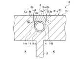
枠状本体部10は、第一外壁部21、第二外壁部22、第三外壁部23及び第四外壁部24を有し、正面視略矩形枠状を呈する。第一外壁部21と第二外壁部22は対向しており、第三外壁部23と第四外壁部24は対向している。第一外壁部21の表面21aには、所定の間隔をあけて蓋溝13が形成されている。蓋溝13は、断面視矩形を呈し、蓋板3がほぼ隙間なく配置される部位である。蓋溝13の数は特に制限されないが、本実施形態では5つ形成されている。各蓋溝13の底面13aには、凹溝14が形成されている。 The frame-like
凹溝14は、円弧状の底面14aと、底面14aに連続する側壁14b,14bとで構成されている。凹溝14の深さは、熱媒体用管4の直径と略同等になっている。底面14aの曲率半径は、熱媒体用管4の曲率半径と同等になっている。各蓋溝13及び各凹溝14は、第一隔壁11の延長線上にそれぞれ形成されている。第二外壁部22の表面22aにも、第一外壁部21と同様に、第一隔壁11と対応する位置に蓋溝13及び凹溝14がそれぞれ形成されている。 The
第三外壁部23及び第四外壁部24は、第一外壁部21及び第二外壁部22の両端をそれぞれ連結する部材である。第一隔壁11は、第一外壁部21と第二外壁部22とを連結しており、所定の間隔をあけて複数体並設されている。第一隔壁11の数は特に制限されないが、本実施形態では5体形成されている。第一隔壁11は、第一外壁部21及び第二外壁部22に対して直角になっている。第一隔壁11の板厚は、特に制限されないが、後記する摩擦攪拌工程の際に、回転ツールGによって作用する押圧力によって中空部Kが変形しない程度の板厚寸法であることが好ましい。 The third
第二隔壁12は、第一外壁部21と第二外壁部22とを連結するとともに中空部Kを斜めに隔てる壁であって、複数体並設されている。第二隔壁12は、第一隔壁11の一端側と、隣り合う第一隔壁11の他端側とを連結している。第二隔壁12の数は特に制限されないが、本実施形態では4体並設されている。枠状本体部10、第一隔壁11及び第二隔壁12でそれぞれ構成された空間が中空部Kとなる。 The
挿入工程は、図4に示すように、各凹溝14に熱媒体用管4を挿入する工程である。熱媒体用管4は、流体が流通する流路となる部位であって本実施形態では円筒状を呈する。熱媒体用管4は、熱伝導性の高い金属で形成されることが好ましく、本実施形態では銅製になっている。なお、熱媒体用管4としてヒーターが内蔵されたヒーター管を用いてもよい。 The insertion step is, as shown in FIG. 4, a step of inserting the
蓋溝閉塞工程は、蓋溝13に蓋板3を配置する工程である。蓋板3は、断面矩形の板状部材であって、蓋溝13にほぼ隙間なく配置される。蓋板3は、熱伝導性の高い金属で形成されることが好ましく、本実施形態ではアルミニウム合金又はアルミニウムで形成されている。蓋板3の裏面3cは、熱媒体用管4の上端と接触するか又はわずかな隙間をあけて配置される。蓋板3の側面3b,3bと蓋溝13の側壁13b,13bとが突き合わされて突合せ部J1,J2が形成される。熱媒体用管4の周囲には、空隙部Q1,Q2が形成される。空隙部Q1,Q2は、熱媒体用管4の外周面と、凹溝14の側壁14bと、蓋板3の裏面3cとで構成される空間である。 The cover groove closing step is a step of arranging the
摩擦攪拌工程は、図5に示すように、突合せ部J1,J2に対して回転ツールGを用いてそれぞれ摩擦攪拌接合をする工程である。回転ツールGは、ショルダ部G1と、攪拌ピンG2とで構成されている。ショルダ部G1は、円柱状を呈する。攪拌ピンG2は、ショルダ部G1の下端面から垂下しており、先細りになっている。攪拌ピンG2の外周面には螺旋溝(図示省略)が刻設されている。 The friction stir process is a process of performing friction stir welding to the butting portions J1 and J2 using the rotary tool G as shown in FIG. The rotating tool G includes a shoulder portion G1 and a stirring pin G2. The shoulder portion G1 has a cylindrical shape. The stirring pin G2 is suspended from the lower end surface of the shoulder portion G1 and is tapered. A spiral groove (not shown) is engraved on the outer peripheral surface of the stirring pin G2.
摩擦攪拌工程では、突合せ部J1に回転した回転ツールGの攪拌ピンG2を挿入しつつ、ショルダ部G1の下端面を蓋板3の表面3a及び第一外壁部21の表面21aに押し込む。そして、突合せ部J1に沿って回転ツールGを相対移動させる。回転ツールGの移動軌跡には、塑性化領域W1が形成される。攪拌ピンG2の挿入深さは、少なくとも空隙部Q1に摩擦熱によって塑性流動化された塑性流動材が流入するように設定する。本実施形態では、攪拌ピンG2が空隙部Q1に達するように攪拌ピンG2の挿入深さを設定している。 In the friction stirring step, the lower end surface of the shoulder portion G1 is pushed into the
摩擦攪拌項工程では、突合せ部J2に対しても突合せ部J1と同じ要領で摩擦攪拌接合を行う。突合せ部J2には、回転ツールGの移動軌跡によって塑性化領域W2が形成される。また、空隙部Q2にも摩擦熱によって塑性流動化された塑性流動材を流入させる。図6に示すように、摩擦攪拌工程によって、突合せ部J1,J2が接合されるとともに、空隙部Q1,Q2が塑性流動材で充填される。摩擦攪拌工程では、同じ要領で中空押出形材2と各蓋板3とを摩擦攪拌接合する。これにより、熱交換器1が形成される。なお、摩擦攪拌工程が終了した後に、摩擦攪拌工程で発生したバリを除去するバリ除去工程を行ってもよい。 In the friction stir process, friction stir welding is performed on the butt portion J2 in the same manner as the butt portion J1. A plasticizing region W2 is formed at the butt portion J2 by the movement trajectory of the rotary tool G. Also, the plastic flow material plasticized and fluidized by the frictional heat is made to flow into the gap Q2. As shown in FIG. 6, in the friction stir process, the abutting portions J1 and J2 are joined, and the gaps Q1 and Q2 are filled with the plastic fluid material. In the friction stirring step, the hollow
以上説明した本実施形態に係る熱交換器の製造方法によれば、押出成形によって、枠状本体部10と第一隔壁11と第二隔壁12とで構成される複数の中空部Kを備えた中空押出形材2が形成される。これにより、熱交換器1を容易に形成することができる。また、ロウ材や接着剤等を介さずに形成できるため、熱伝導率の高い熱交換器1を製造することができる。 According to the method of manufacturing a heat exchanger according to the present embodiment described above, the hollow portions K configured by the frame-shaped
また、第一隔壁11に対応する位置に凹溝14が形成されているため、摩擦攪拌工程時に回転ツールGによって作用する押圧力を第一隔壁11で支持することができる。これにより、中空部Kが変形するのを防ぐことができる。また、本実施形態では、第二隔壁12によっても回転ツールGによって作用する押圧力を支持することができるため、中空部Kの変形をより防ぐことができる。 In addition, since the recessed
また、摩擦攪拌工程では、回転ツールGのショルダ部G1の押圧力を蓋板3を介して熱媒体用管4に伝達させ、凹溝14の底面14aに熱媒体用管4を押し付けながら摩擦攪拌を行う。これにより、凹溝14の底面14aと熱媒体用管4とが密接するため、熱伝導率をより高めることができる。 Further, in the friction stirring step, the pressing force of the shoulder portion G1 of the rotary tool G is transmitted to the
また、摩擦攪拌工程では、熱媒体用管4の周囲に形成された空隙部Q1,Q2に、摩擦熱によって流動化させた塑性流動材を流入させるため、空隙部Q1,Q2が塑性流動材で充填される。これにより、熱交換器1の熱伝導性をより高めることができる。 Further, in the friction stirring step, in order to allow the plastic flow material fluidized by the frictional heat to flow into the gaps Q1 and Q2 formed around the
[変形例]
次に、図7に示すように、第一実施形態の変形例について説明する。変形例では、第二隔壁12を省略した点で第一実施形態と相違する。変形例にかかる熱交換器1Aは、中空押出形材2と、複数の蓋板3と、複数の熱媒体用管4とで主に構成されている。中空押出形材2では、第一実施形態で用いた第二隔壁12を省略し、枠状本体部10と第一隔壁11とで複数の中空部Kを構成している。凹溝14は、第一隔壁11に対応する位置にそれぞれ形成されている。変形例に係る熱交換器1Aは、第二隔壁12が省略されている点を除いてその構造及び製造方法は第一実施形態と同等であるため、詳細な説明は省略する。第二実施形態に係る熱交換器1Aの製造方法によっても、第一実施形態と略同等の効果を得ることができる。[Modification]
Next, as shown in FIG. 7, a modification of the first embodiment will be described. The modification is different from the first embodiment in that the
[第二実施形態]
次に、第二実施形態に係る熱交換器の製造方法について説明する。図8に示すように、本実施形態に係る熱交換器1Bは、中空押出形材42と、複数の蓋板43と、複数の熱媒体用管4とで主に構成されている。中空押出形材42の内部には、複数の中空部Kが形成されている。熱交換器1Bは、熱媒体用管4内を流れる流体と、中空部Kを流れる流体とで熱交換を行う機器である。熱交換器1Bは、蓋板43に対して一の塑性化領域W1が形成されている点で第一実施形態と相違する。Second Embodiment
Next, a method of manufacturing the heat exchanger according to the second embodiment will be described. As shown in FIG. 8, the heat exchanger 1 </ b> B according to the present embodiment is mainly configured by a hollow extruded
図8に示すように、熱媒体用管4は、蓋板3によって中空押出形材42の内部に埋設されている。中空押出形材42と蓋板43との突合せ部は、摩擦攪拌によって接合されている。より詳しくは、中空押出形材42と蓋板43との一対の突合せ部は、一条の塑性化領域W1で接合されている。 As shown in FIG. 8, the
次に、本実施形態に係る熱交換器の製造方法について説明する。本実施形態に係る熱交換器の製造方法は、押出成形工程と、挿入工程と、凹溝閉塞工程と、摩擦攪拌工程とを行う。 Next, a method of manufacturing the heat exchanger according to the present embodiment will be described. The method of manufacturing a heat exchanger according to the present embodiment performs an extrusion molding step, an insertion step, a concave groove closing step, and a friction stirring step.
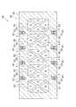
押出成形工程は、図9に示すように、押出成形によって中空押出形材42を成形する工程である。中空押出形材42は、熱伝導性の高い金属で形成されることが好ましく、本実施形態ではアルミニウム又はアルミニウム合金で形成されている。中空押出形材42は、枠状本体部50と、複数の第一隔壁51と、複数の第二隔壁52とで主に構成されている。 The extrusion molding step is a step of molding the hollow extruded
枠状本体部50は、第一外壁部61、第二外壁部62、第三外壁部63及び第四外壁部64を有し、正面視略矩形枠状を呈する。第一外壁部61と第二外壁部62は対向しており、第三外壁部63と第四外壁部64は対向している。第一外壁部61の表面61aには、所定の間隔をあけて凹溝54が形成されている。凹溝54の数は特に制限されないが、本実施形態では4つ形成されている。 The frame-like
凹溝54は、円弧状の底面54aと、底面54aに連続する側壁54b,54bとで構成されている。凹溝54の深さ寸法は、熱媒体用管4の直径と蓋板43の高さ寸法との和よりも若干小さくなるようになっている。凹溝54の幅は、熱媒体用管4の直径と同等になっている。底面54aの曲率半径は、熱媒体用管4の曲率半径と同等になっている。各凹溝54は、第一隔壁51の延長線上にそれぞれ形成されている。第二外壁部62の表面62aにも、第一外壁部61と同様に、第一隔壁51と対応する位置に凹溝54がそれぞれ形成されている。 The recessed
第三外壁部63及び第四外壁部64は、第一外壁部61及び第二外壁部62の両端を連結する部材である。第一隔壁51は、第一外壁部61と第二外壁部62とを連結しており、所定の間隔をあけて複数体並設されている。第一隔壁51は、第一外壁部61及び第二外壁部62に対して直角になっている。第一隔壁51の板厚は、特に制限されないが、後記する摩擦攪拌工程の際に、回転ツールGによって作用する押圧力によって中空部Kが変形しない程度の板厚寸法であることが好ましい。 The third
第二隔壁52,52は、第一外壁部61と第二外壁部62とを連結するとともに中空部Kを斜めに隔てる壁であって、複数体形成されている。第二隔壁52,52は互いに交差して正面視X字状に配置されている。枠状本体部50、第一隔壁51及び第二隔壁52で構成された空間が中空部Kとなる。なお、第二実施形態に係る熱交換器1Bでは、第二隔壁52は省略してもよい。 The
挿入工程は、図10に示すように、各凹溝54に熱媒体用管4を挿入する工程である。凹溝閉塞工程は、熱媒体用管4の上に蓋板43を配置する工程である。蓋板43は、断面矩形の板状部材であって、凹溝54にほぼ隙間なく配置される。蓋板43を熱媒体用管4の上に配置すると、蓋板43の表面43aは、第一外壁部61の表面61aよりも上方にわずかに突出する。 The insertion step is a step of inserting the
蓋板43の側面43b,43bと凹溝54の側壁54b,54bとが突き合わされて突合せ部J1,J2が形成される。熱媒体用管4の周囲には、空隙部Q1,Q2が形成される。空隙部Q1,Q2は、熱媒体用管4の外周面と、凹溝54の側壁54bと、蓋板43の裏面43cとで構成される空間である。 The side surfaces 43b, 43b of the
摩擦攪拌工程は、図11に示すように、突合せ部J1,J2に対して回転ツールGを用いて摩擦攪拌接合をする工程である。回転ツールGは、ショルダ部G1と、攪拌ピンG2とで構成されている。ショルダ部G1は、円柱状を呈する。本実施形態では、ショルダ部G1の直径を凹溝54の幅よりも大きくなるように設定している。攪拌ピンG2は、ショルダ部G1の下端面から垂下しており、先細りになっている。攪拌ピンG2の外周面には螺旋溝が刻設されている。 The friction stir process is a process of performing friction stir welding using the rotating tool G with respect to the abutting portions J1 and J2, as shown in FIG. The rotating tool G includes a shoulder portion G1 and a stirring pin G2. The shoulder portion G1 has a cylindrical shape. In the present embodiment, the diameter of the shoulder portion G1 is set to be larger than the width of the recessed
摩擦攪拌工程では、蓋板43の表面43aの中央に回転した回転ツールGの攪拌ピンG2を挿入しつつ、ショルダ部G1の下端面を第一外壁部61の表面61aに押し込む。そして、突合せ部J1,J2に沿って回転ツールGを相対移動せる。回転ツールGの移動軌跡には、塑性化領域W1が形成される。つまり、摩擦攪拌工程では、回転ツールGを用いて1パスで突合せ部J1,J2を同時に摩擦攪拌接合する。 In the friction stirring step, the lower end surface of the shoulder portion G1 is pushed into the
摩擦攪拌項工程では、同じ要領で中空押出形材42と各蓋板43とを摩擦攪拌接合する。これにより、熱交換器1Bが形成される。なお、摩擦攪拌工程が終了した後に、摩擦攪拌工程で発生したバリを除去するバリ除去工程を行ってもよい。 In the friction stir process, the hollow extruded
以上説明した本実施形態に係る熱交換器の製造方法によれば、押出成形によって、枠状本体部50と第一隔壁51と第二隔壁52とで構成される複数の中空部Kを備えた中空押出形材42が形成される。これにより、熱交換器1Bを容易に形成することができる。また、ロウ材や接着剤等を介さずに形成できるため、熱伝導率の高い熱交換器1Bを製造することができる。 According to the method of manufacturing a heat exchanger according to the embodiment described above, the hollow portions K configured by the frame-shaped
また、第一隔壁51に対応する位置に凹溝54が形成されているため、摩擦攪拌工程時に回転ツールGによって作用する押圧力を第一隔壁51で支持することができる。これにより、中空部Kが変形するのを防ぐことができる。また、本実施形態では、第二隔壁52,52によっても回転ツールGによって作用する押圧力を支持することができるため、中空部Kの変形をより防ぐことができる。 In addition, since the recessed
また、摩擦攪拌工程では、回転ツールGのショルダ部G1の押圧力を蓋板43を介して熱媒体用管4に伝達させ、凹溝54の底面54aに熱媒体用管4を押し付けながら摩擦攪拌を行う。これにより、凹溝54の底面54aと熱媒体用管4とが密接するため、熱伝導率をより高めることができる。 Further, in the friction stirring process, the pressing force of the shoulder portion G1 of the rotary tool G is transmitted to the
また、摩擦攪拌工程では、蓋板43の表面43aを、第一外壁部61の表面61aよりも突出させた状態で蓋板43に回転ツールGを挿入するため、摩擦攪拌接合による金属不足を補うことができる。 Further, in the friction stir process, the rotation tool G is inserted into the
以上本発明の実施形態について説明したが、本発明の趣旨に反しない範囲において適宜設計変更が可能である。例えば、本実施形態では、凹溝と隔壁とを対応する位置に設けたが、対応しない位置に凹溝を設けてもよい。また、本実施形態では、第一外壁部と第二外壁部の両方の表面に熱媒体用管4を埋設する構成としたが、第一外壁部及び第二外壁部の少なくとも一方に熱媒体用管4を埋設する構成としてもよい。また、第二実施形態において、第一外壁部61の表面61aと蓋板43の表面43aとを面一にした状態で、摩擦攪拌工程を行ってもよい。 Although the embodiments of the present invention have been described above, design changes can be made as appropriate without departing from the spirit of the present invention. For example, in the present embodiment, the recessed groove and the partition wall are provided at corresponding positions, but the recessed groove may be provided at a position not corresponding. Further, in the present embodiment, the
1 熱交換器
2 中空押出形材
3 蓋板
4 熱媒体用管
11 第一隔壁(隔壁)
12 第二隔壁(隔壁)
13 蓋溝
14 凹溝
21 第一外壁部(外壁部)
22 第二外壁部(外壁部)
23 第三外壁部
24 第四外壁部
G 回転ツール
G1 ショルダ部
G2 攪拌ピン
J1 突合せ部
J2 突合せ部
Q1 空隙部
Q2 空隙部Reference Signs List 1
12 Second partition (partition)
13
22 second outer wall (outer wall)
23 third
Claims (8)
Translated fromJapanese前記凹溝に熱媒体用管を挿入する挿入工程と、
前記蓋溝に蓋板を配置する蓋溝閉塞工程と、
前記蓋溝の側壁と前記蓋板の側面との突合せ部に回転する回転ツールを相対移動させて摩擦攪拌接合を施す摩擦攪拌工程と、を含むことを特徴とする熱交換器の製造方法。A frame-shaped main body formed to include a pair of opposing outer walls, a plurality of partitions arranged side by side connecting the outer walls, and a cover groove formed on at least one surface of the pair of outer walls And an extrusion forming step of forming a hollow extruded section provided with a concave groove formed on the bottom surface of the lid groove;
Inserting the heat medium pipe into the concave groove;
A lid groove closing step of arranging a lid plate in the lid groove;
A method of manufacturing a heat exchanger, comprising: a friction stirring step of relatively moving a rotating tool that rotates at a butt between a side wall of the lid groove and a side surface of the lid plate to perform friction stir welding.
前記凹溝に熱媒体用管を挿入する挿入工程と、
前記熱媒体用管の上に蓋板を配置する凹溝閉塞工程と、
前記凹溝の側壁と前記蓋板の側面との突合せ部に回転する回転ツールを相対移動させて摩擦攪拌接合を施す摩擦攪拌工程と、を含むことを特徴とする熱交換器の製造方法。A frame-shaped main body formed to include a pair of opposing outer walls, a plurality of partitions arranged side by side connecting the outer walls, and a groove formed on at least one surface of the pair of outer walls And extruding a hollow extruded section comprising:
Inserting the heat medium pipe into the concave groove;
A concave groove closing step of disposing a lid plate on the heat medium pipe;
A method of manufacturing a heat exchanger, comprising: a friction stirring step of relatively moving a rotating tool that rotates at a butt between a side wall of the recessed groove and a side surface of the lid plate to perform friction stir welding.
Priority Applications (1)
| Application Number | Priority Date | Filing Date | Title |
|---|---|---|---|
| JP2015166410AJP6547517B2 (en) | 2015-08-26 | 2015-08-26 | Heat exchanger manufacturing method |
Applications Claiming Priority (1)
| Application Number | Priority Date | Filing Date | Title |
|---|---|---|---|
| JP2015166410AJP6547517B2 (en) | 2015-08-26 | 2015-08-26 | Heat exchanger manufacturing method |
Related Child Applications (1)
| Application Number | Title | Priority Date | Filing Date |
|---|---|---|---|
| JP2019108397ADivisionJP2019158334A (en) | 2019-06-11 | 2019-06-11 | Heat exchanger |
Publications (2)
| Publication Number | Publication Date |
|---|---|
| JP2017042782A JP2017042782A (en) | 2017-03-02 |
| JP6547517B2true JP6547517B2 (en) | 2019-07-24 |
Family
ID=58211022
Family Applications (1)
| Application Number | Title | Priority Date | Filing Date |
|---|---|---|---|
| JP2015166410AActiveJP6547517B2 (en) | 2015-08-26 | 2015-08-26 | Heat exchanger manufacturing method |
Country Status (1)
| Country | Link |
|---|---|
| JP (1) | JP6547517B2 (en) |
Families Citing this family (1)
| Publication number | Priority date | Publication date | Assignee | Title |
|---|---|---|---|---|
| US20170197274A1 (en)* | 2014-07-10 | 2017-07-13 | Megastir Technologies Llc | Mechanical flow joining of high melting temperature materials |
Family Cites Families (5)
| Publication number | Priority date | Publication date | Assignee | Title |
|---|---|---|---|---|
| JP3070735B2 (en)* | 1997-07-23 | 2000-07-31 | 株式会社日立製作所 | Friction stir welding method |
| JP5045355B2 (en)* | 2007-10-04 | 2012-10-10 | 日本軽金属株式会社 | Method for producing shape and shape |
| JP5071249B2 (en)* | 2008-06-03 | 2012-11-14 | 日本軽金属株式会社 | Heat transfer plate manufacturing method and heat transfer plate |
| JP2010266174A (en)* | 2009-05-18 | 2010-11-25 | Showa Denko Kk | Heat exchanger |
| JP5754431B2 (en)* | 2012-10-10 | 2015-07-29 | 日本軽金属株式会社 | Heat sink manufacturing method and heat transfer plate manufacturing method |
- 2015
- 2015-08-26JPJP2015166410Apatent/JP6547517B2/enactiveActive
Also Published As
| Publication number | Publication date |
|---|---|
| JP2017042782A (en) | 2017-03-02 |
Similar Documents
| Publication | Publication Date | Title |
|---|---|---|
| CN101657289B (en) | Heat transfer plate and manufacturing method thereof | |
| JP4707388B2 (en) | Heat transfer tube for combustion exhaust gas containing soot and heat exchanger assembled with this heat transfer tube | |
| JP6372516B2 (en) | Liquid cooling jacket manufacturing method and liquid cooling jacket | |
| JP5754431B2 (en) | Heat sink manufacturing method and heat transfer plate manufacturing method | |
| CN107429976B (en) | Heat exchanger with plate having surface pattern for improving flatness and method of manufacturing the same | |
| JP5163419B2 (en) | Manufacturing method of heat transfer plate | |
| JP2017042817A5 (en) | ||
| JPH07227631A (en) | Guide tube for heat exchanging in laminated layer type heat exchanger and its manufacture | |
| JP5168212B2 (en) | Manufacturing method of liquid cooling jacket | |
| CN103624396A (en) | Method of manufacturing heat transfer plate | |
| JP2018179493A (en) | Manifold for heat exchanger, heat exchanger, and production method thereof | |
| JPH1147960A (en) | Heat exchanger | |
| CN102056700B (en) | Manufacturing method of heat conduction plate and heat conduction plate | |
| JP6547517B2 (en) | Heat exchanger manufacturing method | |
| JP6015622B2 (en) | Manufacturing method of heat transfer plate | |
| JP2006017131A (en) | Connected body and connection method | |
| JP5195098B2 (en) | Manufacturing method of heat transfer plate | |
| JP5141487B2 (en) | Manufacturing method of heat transfer plate | |
| US20150144309A1 (en) | Flattened Envelope Heat Exchanger | |
| JP5725098B2 (en) | Manufacturing method of liquid cooling jacket | |
| JP6326753B2 (en) | Heat exchanger | |
| JP2019158334A (en) | Heat exchanger | |
| KR20020086523A (en) | Fin-Tube Type Heat Exchanger with Grooved Spacer Bars | |
| TWI437200B (en) | Heat exchanger | |
| JP2009178762A (en) | Manufacturing method of heat transfer plate |
Legal Events
| Date | Code | Title | Description |
|---|---|---|---|
| A621 | Written request for application examination | Free format text:JAPANESE INTERMEDIATE CODE: A621 Effective date:20180130 | |
| A977 | Report on retrieval | Free format text:JAPANESE INTERMEDIATE CODE: A971007 Effective date:20181121 | |
| A131 | Notification of reasons for refusal | Free format text:JAPANESE INTERMEDIATE CODE: A131 Effective date:20181127 | |
| A521 | Request for written amendment filed | Free format text:JAPANESE INTERMEDIATE CODE: A523 Effective date:20181217 | |
| TRDD | Decision of grant or rejection written | ||
| A01 | Written decision to grant a patent or to grant a registration (utility model) | Free format text:JAPANESE INTERMEDIATE CODE: A01 Effective date:20190528 | |
| A61 | First payment of annual fees (during grant procedure) | Free format text:JAPANESE INTERMEDIATE CODE: A61 Effective date:20190610 | |
| R150 | Certificate of patent or registration of utility model | Ref document number:6547517 Country of ref document:JP Free format text:JAPANESE INTERMEDIATE CODE: R150 | |
| S531 | Written request for registration of change of domicile | Free format text:JAPANESE INTERMEDIATE CODE: R313531 | |
| R350 | Written notification of registration of transfer | Free format text:JAPANESE INTERMEDIATE CODE: R350 | |
| R250 | Receipt of annual fees | Free format text:JAPANESE INTERMEDIATE CODE: R250 | |
| R250 | Receipt of annual fees | Free format text:JAPANESE INTERMEDIATE CODE: R250 |