JP6546656B2 - Single focus optical system and optical apparatus provided with the same - Google Patents
Single focus optical system and optical apparatus provided with the sameDownload PDFInfo
- Publication number
- JP6546656B2 JP6546656B2JP2017521368AJP2017521368AJP6546656B2JP 6546656 B2JP6546656 B2JP 6546656B2JP 2017521368 AJP2017521368 AJP 2017521368AJP 2017521368 AJP2017521368 AJP 2017521368AJP 6546656 B2JP6546656 B2JP 6546656B2
- Authority
- JP
- Japan
- Prior art keywords
- lens
- optical system
- group
- focus optical
- negative
- Prior art date
- Legal status (The legal status is an assumption and is not a legal conclusion. Google has not performed a legal analysis and makes no representation as to the accuracy of the status listed.)
- Active
Links
Images


Classifications
- G—PHYSICS
- G02—OPTICS
- G02B—OPTICAL ELEMENTS, SYSTEMS OR APPARATUS
- G02B9/00—Optical objectives characterised both by the number of the components and their arrangements according to their sign, i.e. + or -
- G02B9/64—Optical objectives characterised both by the number of the components and their arrangements according to their sign, i.e. + or - having more than six components
- G—PHYSICS
- G02—OPTICS
- G02B—OPTICAL ELEMENTS, SYSTEMS OR APPARATUS
- G02B13/00—Optical objectives specially designed for the purposes specified below
- G02B13/04—Reversed telephoto objectives
- G—PHYSICS
- G02—OPTICS
- G02B—OPTICAL ELEMENTS, SYSTEMS OR APPARATUS
- G02B13/00—Optical objectives specially designed for the purposes specified below
- G02B13/001—Miniaturised objectives for electronic devices, e.g. portable telephones, webcams, PDAs, small digital cameras
- G02B13/0015—Miniaturised objectives for electronic devices, e.g. portable telephones, webcams, PDAs, small digital cameras characterised by the lens design
- G02B13/002—Miniaturised objectives for electronic devices, e.g. portable telephones, webcams, PDAs, small digital cameras characterised by the lens design having at least one aspherical surface
- G02B13/0045—Miniaturised objectives for electronic devices, e.g. portable telephones, webcams, PDAs, small digital cameras characterised by the lens design having at least one aspherical surface having five or more lenses
- G—PHYSICS
- G02—OPTICS
- G02B—OPTICAL ELEMENTS, SYSTEMS OR APPARATUS
- G02B13/00—Optical objectives specially designed for the purposes specified below
- G02B13/001—Miniaturised objectives for electronic devices, e.g. portable telephones, webcams, PDAs, small digital cameras
- G02B13/0055—Miniaturised objectives for electronic devices, e.g. portable telephones, webcams, PDAs, small digital cameras employing a special optical element
- G02B13/006—Miniaturised objectives for electronic devices, e.g. portable telephones, webcams, PDAs, small digital cameras employing a special optical element at least one element being a compound optical element, e.g. cemented elements
- G—PHYSICS
- G02—OPTICS
- G02B—OPTICAL ELEMENTS, SYSTEMS OR APPARATUS
- G02B13/00—Optical objectives specially designed for the purposes specified below
- G02B13/18—Optical objectives specially designed for the purposes specified below with lenses having one or more non-spherical faces, e.g. for reducing geometrical aberration
- G—PHYSICS
- G02—OPTICS
- G02B—OPTICAL ELEMENTS, SYSTEMS OR APPARATUS
- G02B21/00—Microscopes
- G02B21/36—Microscopes arranged for photographic purposes or projection purposes or digital imaging or video purposes including associated control and data processing arrangements
- G—PHYSICS
- G02—OPTICS
- G02B—OPTICAL ELEMENTS, SYSTEMS OR APPARATUS
- G02B5/00—Optical elements other than lenses
- G02B5/005—Diaphragms
- G—PHYSICS
- G02—OPTICS
- G02B—OPTICAL ELEMENTS, SYSTEMS OR APPARATUS
- G02B7/00—Mountings, adjusting means, or light-tight connections, for optical elements
- G02B7/02—Mountings, adjusting means, or light-tight connections, for optical elements for lenses
- G02B7/021—Mountings, adjusting means, or light-tight connections, for optical elements for lenses for more than one lens
- G—PHYSICS
- G02—OPTICS
- G02B—OPTICAL ELEMENTS, SYSTEMS OR APPARATUS
- G02B7/00—Mountings, adjusting means, or light-tight connections, for optical elements
- G02B7/02—Mountings, adjusting means, or light-tight connections, for optical elements for lenses
- G02B7/04—Mountings, adjusting means, or light-tight connections, for optical elements for lenses with mechanism for focusing or varying magnification
Landscapes
- Physics & Mathematics (AREA)
- General Physics & Mathematics (AREA)
- Optics & Photonics (AREA)
- Lenses (AREA)
- Projection Apparatus (AREA)
Description
Translated fromJapanese本発明は、単焦点光学系及びそれを備えた光学装置に関する。 The present invention relates to a single focus optical system and an optical apparatus provided with the same.
高い結像性能を有する結像光学系のタイプとして、ガウスタイプが知られている。ガウスタイプの光学系は、物体側から順に、正の屈折力を有する物体側群と、正の屈折力を有する像側群と、より構成されている。 The Gaussian type is known as a type of imaging optical system having high imaging performance. The Gauss type optical system is composed of, in order from the object side, an object side group having positive refractive power and an image side group having positive refractive power.
物体側群は、2枚乃至3枚の正レンズと、1枚の負レンズとからなる。この負レンズは、直前の正レンズと接合されている場合がある。また、像側群は、1枚の負レンズと、2枚乃至3枚の正レンズと、からなる。この負レンズも、直後の正レンズと接合されている場合がある。 The object side group includes two to three positive lenses and one negative lens. This negative lens may be cemented with the immediately preceding positive lens. The image side group is composed of one negative lens and two to three positive lenses. This negative lens may also be cemented with the immediately following positive lens.
また、ガウスタイプの光学系は、その中央部を境に物体側の形状と像側の形状がおおむね対称で、且つコンセントリックな形状になっている。コンセントリックな形状では、各レンズで、2つのレンズ面における曲率中心が中央部の近くに位置している。 Further, the Gauss-type optical system has a shape on the object side and a shape on the image side that are substantially symmetrical with respect to the center of the central portion, and has a concentric shape. In the concentric shape, in each lens, the centers of curvature of the two lens surfaces are located near the center.
これにより、ガウスタイプの光学系では、大口径比であっても、各収差がある程度良好に補正できている。しかし、従来以上の結像性能を実現しようとすると、ガウスタイプの光学系では画角50度弱が限界である。よって、ガウスタイプの光学系で、50度以上の画角の実現は困難である。 As a result, in the Gaussian type optical system, each aberration can be well corrected to some extent even at a large aperture ratio. However, in order to realize the imaging performance more than the conventional one, the field angle of less than 50 degrees is the limit in the Gaussian type optical system. Therefore, it is difficult to realize an angle of view of 50 degrees or more with a Gaussian type optical system.
これらの問題を解決した広角撮影レンズが、各種提案されている。提案されている広角撮影レンズでは、Fナンバーが1.4程度になっている。画角が広くFナンバーが小さい広角撮影レンズの光学系として、特許文献1〜6に開示された光学系がある。 Various wide-angle shooting lenses that solve these problems have been proposed. The proposed wide-angle shooting lens has an f-number of around 1.4. As an optical system of a wide angle photographing lens having a wide angle of view and a small F number, there are optical systems disclosed in
特許文献1や特許文献2の光学系ではFナンバーが1.24であるため、Fナンバーが小さい光学系が実現できている。しかしながら、画角が63.6°であるため、特許文献1や特許文献2の光学系では、画角が十分に広い光学系が実現できていない。 In the optical systems of
また、特許文献3、特許文献4、特許文献5及び特許文献6の光学系では、Fナンバーが1.4であるが、これ以上Fナンバーを小さくしようとするか、又は画角を広くしようとすると、上述した諸収差の補正がさらに困難となる。 Further, in the optical systems of
本発明は、このような課題に鑑みてなされたものであって、広い画角と小さいFナンバーを有しながらも、諸収差が良好に補正された単焦点光学系及びそれを備えた光学装置を提供することを目的とする。 The present invention has been made in view of such problems, and has a wide angle of view and a small f-number, but a single-focus optical system in which various aberrations are well corrected, and an optical apparatus provided with the same. Intended to provide.
上述した課題を解決し、目的を達成するために、本発明の単焦点光学系は、
距離が長い方の拡大側の共役点と距離が短い方の縮小側の共役点との共役関係を形成する単焦点光学系であって、
単焦点光学系は、拡大側から順に、
負の屈折力を有する第1レンズ群と、
正の屈折力を有する第2レンズ群と、
正の屈折力を有する第3レンズ群と、から構成され、
レンズ成分は、単レンズ又は接合レンズであり、
第1レンズ群は、最も拡大側に拡大側レンズ成分を有し、
拡大側レンズ成分は、拡大側に凸面を向けた負メニスカスレンズ成分であり、
第1レンズ群は、最も縮小側に、接合レンズである縮小側レンズ成分を有し、
縮小側レンズ成分の形状は、拡大側に凸面を向けたメニスカス形状であり、拡大側から順に、正レンズと負レンズとで構成され、
接合レンズよりも拡大側のレンズ系は、全体として負の焦点距離を有すると共に、拡大側レンズ成分のみからなるか、拡大側レンズ成分と負レンズとを有するか、又は、拡大側レンズ成分と正レンズとを有し、
第2レンズ群は、拡大側から順に、縮小側に凸面を向けたメニスカス形状の接合レンズと、複数の正レンズ成分と、からなり、
その複数の正レンズ成分は、隣り合う全ての正レンズ成分を含み、
第2レンズ群の接合レンズは、拡大側から順に、負レンズと正レンズとで構成され、
第3レンズ群は、最も拡大側に負レンズ成分を有し、
第1レンズ群内の全ての空気間隔と第2レンズ群内の全ての空気間隔は、フォーカス時に一定であることを特徴とする。In order to solve the problems described above and achieve the purpose, the single-focus optical system of the present invention is
A single-focus optical system which forms a conjugate relationship between a conjugate point on the enlargement side with a long distance and a conjugate point on the reduction side with a short distance,
The single-focus optical system
A first lens group having negative refractive power;
A second lens group having a positive refractive power;
And a third lens unit having a positive refractive power,
The lens component is a single lens or a cemented lens,
The first lens group has an enlargement side lens component on the most enlargement side,
The magnifying side lens component is a negative meniscus lens component having a convex surface on the magnifying side,
The first lens group has, on the most reduction side, a reduction side lens componentwhich is a cemented lens ,
The shape of the reduction side lens component is a meniscus shape with a convex surface facing theenlargement side, and is composed of a positive lens and a negative lens in order from theenlargement side,
The lens system on the magnification side of the cemented lens has a negative focal length as a whole and is made up of only the magnification side lens component, or has the magnification side lens component and the negative lens, or the magnification side lens component and the positive lens component Have a lens and
The second lens unit includes, in order from the enlargement side, a meniscus cemented lens having a convex surface facing the reduction side, and a plurality of positive lens components,
The plurality of positive lens components includes all adjacent positive lens components,
The cemented lens in the second lens group is composed of, in order from the magnification side, a negative lens and a positive lens,
The third lens unit has a negative lens component on the most enlargement side,
All air gaps in the first lens group and all air gaps in the second lens group are characterized in that they are constant at the time of focusing.
また、本発明の光学装置は、
光学系と、縮小側に配置された撮像素子と、を有し、
撮像素子は撮像面を有し、且つ光学系によって撮像面上に形成された像を電気信号に変換し、
光学系が上述の単焦点光学系であることを特徴とする。Also, the optical device of the present invention is
An optical system and an imaging device disposed on the reduction side,
The imaging device has an imaging surface, and converts an image formed on the imaging surface by the optical system into an electrical signal,
The optical system is characterized in that it is the above-mentioned single-focus optical system.
また、本発明の別の光学装置は、
光学系と、縮小側に配置された表示素子と、を有し、
表示素子は表示面を有し、
表示面上に表示された画像は、光学系によって拡大側に投影され、
光学系が上述の単焦点光学系であることを特徴とする。Also, another optical device of the present invention is
An optical system, and a display element disposed on the reduction side,
The display element has a display surface,
The image displayed on the display surface is projected to the enlargement side by the optical system,
The optical system is characterized in that it is the above-mentioned single-focus optical system.
本発明によれば、広い画角と小さいFナンバーを有しながらも、諸収差が良好に補正された単焦点光学系及びそれを備えた光学装置を提供することができる。 According to the present invention, it is possible to provide a single-focus optical system in which various aberrations are well corrected while having a wide angle of view and a small f-number, and an optical apparatus provided with the same.
以下に、本発明に係る単焦点光学系及びそれを備えた光学装置の実施形態及び実施例を、図面に基づいて詳細に説明する。なお、この実施形態及び実施例によりこの発明が限定されるものではない。 Hereinafter, embodiments and examples of the single-focus optical system and the optical apparatus provided with the single-focus optical system according to the present invention will be described in detail based on the drawings. The present invention is not limited by the embodiments and the examples.
本実施形態の単焦点光学系は、距離が長い方の拡大側の共役点と距離が短い方の縮小側の共役点との共役関係を形成する単焦点光学系であって、単焦点光学系は、拡大側から順に、負の屈折力を有する第1レンズ群と、正の屈折力を有する第2レンズ群と、正の屈折力を有する第3レンズ群と、から構成され、レンズ成分は、単レンズ又は接合レンズであり、第1レンズ群は、最も縮小側に縮小側レンズ成分を有し、縮小側レンズ成分の形状は、拡大側に凸面を向けたメニスカス形状であり、第2レンズ群は、拡大側から順に、縮小側に凸面を向けたメニスカス形状の接合レンズと、複数の正レンズ成分と、からなり、その複数の正レンズ成分は、隣り合う全ての正レンズ成分を含み、第2レンズ群の接合レンズは、拡大側から順に、負レンズと正レンズとで構成され、第3レンズ群は、最も拡大側に負レンズ成分を有し、第1レンズ群内の全ての空気間隔と第2レンズ群内の全ての空気間隔は、フォーカス時に一定であることを特徴とする。 The single-focus optical system according to the present embodiment is a single-focus optical system that forms a conjugate relationship between a conjugate point on the enlargement side with a long distance and a conjugate point on the reduction side with a short distance. Is composed of, in order from the enlargement side, a first lens group having negative refractive power, a second lens group having positive refractive power, and a third lens group having positive refractive power, and the lens component is The first lens group has a reduction side lens component on the most reduction side, and the shape of the reduction side lens component is a meniscus shape having a convex surface on the enlargement side, and the second lens The group consists of, in order from the magnification side, a cemented lens having a convex surface facing the reduction side and a plurality of positive lens components, and the plurality of positive lens components include all adjacent positive lens components, The cemented lens in the second lens group is a negative lens in order from the enlargement side. The third lens group has a negative lens component on the most enlargement side, and all air gaps in the first lens group and all air gaps in the second lens group are in focus. It is characterized by being constant.
本実施形態の単焦点光学系とガウスタイプの光学系とを比較しながら、本実施形態の単焦点光学系について説明する。以下の説明では、拡大側に物体側が対応し、縮小側に像側が対応する。 The single focus optical system of the present embodiment will be described while comparing the single focus optical system of the present embodiment with a Gaussian type optical system. In the following description, the object side corresponds to the enlargement side, and the image side corresponds to the reduction side.
本実施形態の単焦点光学系は、ガウスタイプの光学系をベースにしている。すなわち、ガウスタイプにおける基本的なレンズの配列やレンズの形状(以下、「基本配列」という)を極力維持しつつ、様々な工夫を加えている。例えば、本実施形態の単焦点光学系の第1レンズ群には、ガウスタイプの物体側群が対応する。よって、第1レンズ群は、ガウスタイプの物体側群と同様の基本配列を備えている。 The single-focus optical system of the present embodiment is based on a Gaussian type optical system. That is, various ideas are added while maintaining the basic arrangement of lenses in the Gaussian type and the shape of the lenses (hereinafter referred to as "basic arrangement") as much as possible. For example, a Gaussian type object side group corresponds to the first lens group of the single focal length optical system of the present embodiment. Thus, the first lens group has the same basic arrangement as the Gaussian type object side group.
ただし、本実施形態の単焦点光学系では、第1レンズ群の屈折力を負の屈折力にしている。これは、ガウスタイプの物体側群における基本配列を極力維持しつつ、物体側群における正の屈折力を負側にシフトさせたことに相当する。屈折力の負側へのシフトとは、正の屈折力を小さな負の屈折力に変更することや、正の屈折力をより小さな正の屈折力にすることである。 However, in the single-focus optical system of the present embodiment, the refractive power of the first lens group is made negative. This corresponds to shifting the positive refractive power in the object side group to the negative side while maintaining the basic arrangement in the Gaussian type object side group as much as possible. The shift to the negative side of the refractive power is to change the positive refractive power to a small negative refractive power or to make the positive refractive power a smaller positive refractive power.
本実施形態の単焦点光学系では、屈折力の負側へのシフトによって、第1レンズ群の屈折力に負の屈折力を与えているが、これに伴い、第2レンズ群と第3レンズ群に大きな屈折力を与えている。第2レンズ群と第3レンズ群は、ガウスタイプの像側群に対応する。よって、第2レンズ群と第3レンズ群に大きな屈折力を与えることは、ガウスタイプの物体側群の正の屈折力を負側にシフトしたことに伴い、ガウスタイプの像側群の正の屈折力を正側に大きくシフトさせたことに相当する。 In the single-focus optical system of the present embodiment, the negative refractive power is given to the refractive power of the first lens group by the shift of the refractive power to the negative side, but along with this, the second lens group and the third lens Gives the group great power. The second lens group and the third lens group correspond to a Gaussian type image side group. Therefore, giving a large refracting power to the second lens group and the third lens group means that the positive refracting power of the Gaussian type object side group is shifted to the negative side. It corresponds to that the refractive power is largely shifted to the positive side.
このように、本実施形態の単焦点光学系では、ガウスタイプの光学系に対して、物体側群における屈折力の負側へのシフトと像側群における正の屈折力の増大を行った構成を採用している。そのため、屈折力の配置に関して、本実施形態の結像光学はガウスタイプの光学系とは異なる。 As described above, in the single-focus optical system of the present embodiment, a configuration in which the negative shift of the refractive power in the object side group and the increase of the positive refractive power in the image side group are performed with respect to the Gaussian type optical system. Is adopted. Therefore, with regard to the arrangement of refractive power, the imaging optics of the present embodiment is different from the Gaussian type optical system.
しかしながら、本実施形態の単焦点光学系も、ガウスタイプの基本配列を備えている。よって、本実施形態の単焦点光学系は、収差補正のポテンシャルが極めて高い光学系をベースにしているということができる。そのため、本実施形態の単焦点光学系では、特に、球面収差、コマ収差、軸上色収差及び倍率色収差を極めて良好に補正できる。その結果、従来のガウスタイプの光学系よりも高い結像性能を有する単焦点光学系を実現することができる。例えば、単焦点光学系において、1.4よりも小さいFナンバーと、50°以上の画角を確保することができる。 However, the single-focus optical system of the present embodiment also has a basic array of Gaussian type. Therefore, it can be said that the single-focus optical system of the present embodiment is based on an optical system in which the potential for aberration correction is extremely high. Therefore, in the single-focus optical system of the present embodiment, in particular, spherical aberration, coma, axial chromatic aberration and lateral chromatic aberration can be corrected extremely well. As a result, it is possible to realize a single focus optical system having an imaging performance higher than that of the conventional Gaussian type optical system. For example, in a single-focus optical system, an F number smaller than 1.4 and an angle of view of 50 ° or more can be secured.
このように、本実施形態の単焦点光学系によれば、標準レンズから広角レンズのカテゴリーにおいて、1.4よりも小さいFナンバーを有し、かつ、収差補正のポテンシャルが極めて高い単焦点光学系を提供することができる。特に、結像性能においては、従来の35mmフィルムサイズ用の単焦点光学系を凌駕するレベルの結像性能を有することができる。 As described above, according to the single-focus optical system of the present embodiment, a single-focus optical system having an f-number smaller than 1.4 and having an extremely high aberration correction potential in the categories from standard lenses to wide-angle lenses. Can be provided. In particular, in imaging performance, it can have imaging performance at a level that surpasses conventional single-focus optical systems for 35 mm film size.
また、本実施形態の単焦点光学系では、第1レンズ群は、最も拡大側に拡大側レンズ成分を有し、拡大側レンズ成分は負の単レンズであることが好ましい。 Further, in the single focus optical system of the present embodiment, it is preferable that the first lens group has the enlargement side lens component on the most enlargement side, and the enlargement side lens component is a negative single lens.
このようにすることで、光学系を広角化しても、第1レンズ群の大型化を防止することができる。 By doing this, it is possible to prevent the enlargement of the first lens group even if the optical system is widened.
また、本実施形態の単焦点光学系では、第1レンズ群は正レンズを含むことが好ましい。 Moreover, in the single focus optical system of the present embodiment, it is preferable that the first lens group includes a positive lens.
このようにすることで、軸上色収差、倍率色収差及び像面湾曲をより良好に補正できる。 By doing this, axial chromatic aberration, lateral chromatic aberration, and field curvature can be corrected better.
また、本実施形態の単焦点光学系では、縮小側レンズ成分は接合レンズであり、第1レンズ群の縮小側レンズ成分は、拡大側から順に、正レンズと負レンズとで構成されていることが好ましい。 In the single-focus optical system according to this embodiment, the reduction side lens component is a cemented lens, and the reduction side lens component of the first lens group is composed of a positive lens and a negative lens in order from the enlargement side. Is preferred.
このようにすることで、球面収差、コマ収差、非点収差及び像面湾曲、更には軸上色収差や倍率色収差をより良好に補正できる。 In this way, spherical aberration, coma, astigmatism, curvature of field, and axial chromatic aberration and lateral chromatic aberration can be corrected better.
また、本実施形態の単焦点光学系では、第2レンズ群は、最も縮小側に縮小側正レンズ成分を有し、縮小側正レンズ成分は単レンズであることが好ましい。 Further, in the single focus optical system of the present embodiment, it is preferable that the second lens group has a reduction side positive lens component on the most reduction side, and the reduction side positive lens component is a single lens.
本実施形態の単焦点光学系では、第2レンズ群と第3レンズ群が、従来のガウスタイプの光学系における像側群に相当する。そこで、このようにすることで、少ない構成枚数でありながら、第2レンズ群と第3レンズ群との合成系の合成屈折力を大きくしても、球面収差、コマ収差、非点収差及び像面湾曲、更には軸上色収差や倍率色収差をより良好に無理なく補正できる。 In the single focus optical system of the present embodiment, the second lens group and the third lens group correspond to the image side group in the conventional Gaussian type optical system. Therefore, even if the combined refractive power of the second lens group and the third lens group is increased, the spherical aberration, coma, astigmatism, and image can be obtained even though the number of components is small. It is possible to correct the surface curvature and also the axial chromatic aberration and the lateral chromatic aberration better and unreasonably.
また、本実施形態の単焦点光学系では、第2レンズ群中の前述の複数の正レンズ成分は全て単レンズであることが好ましい。 Further, in the single focus optical system of the present embodiment, it is preferable that the plurality of positive lens components in the second lens group are all single lenses.
本実施形態の単焦点光学系では、第2レンズ群と第3レンズ群が、従来のガウスタイプの光学系における像側群に相当する。そこで、このようにすることで、少ない構成枚数でありながら、第2レンズ群と第3レンズ群との合成系の合成屈折力を大きくしても、球面収差、コマ収差、非点収差及び像面湾曲、更には軸上色収差や倍率色収差をより良好に無理なく補正できる。 In the single focus optical system of the present embodiment, the second lens group and the third lens group correspond to the image side group in the conventional Gaussian type optical system. Therefore, even if the combined refractive power of the second lens group and the third lens group is increased, the spherical aberration, coma, astigmatism, and image can be obtained even though the number of components is small. It is possible to correct the surface curvature and also the axial chromatic aberration and the lateral chromatic aberration better and unreasonably.
また、本実施形態の単焦点光学系では、第3レンズ群は、拡大側から順に、第1副群と、第2副群と、第3副群と、からなり、第1副群は1つの負レンズ成分のみからなり、第2副群は1つの正レンズ成分のみからなることが好ましい。 In the single-focus optical system of the present embodiment, the third lens unit includes, in order from the enlargement side, the first sub-group, the second sub-group, and the third sub-group, and the first sub-group includes 1 Preferably, the second sub group consists of only one negative lens component.
口径比が大きい光学系では、特に、球面収差、コマ収差及び非点収差については、良好に補正することが厳しく求められる。そこで、このようにすることで、少ない構成枚数でありながら、第2レンズ群と第3レンズ群における屈折力を大きくしつつも、第1副群と第2副群とで相互に収差を打ち消しあうことができる。その結果、球面収差、コマ収差及び非点収差を、全体としてバランス良く補正することができる。 In an optical system having a large aperture ratio, in particular, spherical aberration, coma and astigmatism are required to be well corrected. Therefore, this makes it possible to cancel the mutual aberration between the first sub-group and the second sub-group while increasing the refractive powers of the second lens group and the third lens group while having a small number of components. Can meet. As a result, spherical aberration, coma and astigmatism can be corrected in a well-balanced manner as a whole.
また、第3レンズ群のレンズ成分でインナーフォーカスを行うことを考えた場合には、第1副群の負レンズ成分を光軸に沿って移動することにより、移動させるレンズを軽量にすることができる。その結果、高速で、且つ収差変動の極めて少ないフォーカスが可能となる。 In addition, when performing inner focusing with the lens component of the third lens group, the weight of the lens to be moved can be reduced by moving the negative lens component of the first sub group along the optical axis. it can. As a result, focusing can be performed at high speed and with very little aberration fluctuation.
また、本実施形態の単焦点光学系では、第3レンズ群は、拡大側から順に、第1副群と、第2副群と、第3副群と、からなり、第1副群は1つの負レンズ成分のみからなり、第2副群は1つの正レンズ成分のみからなり、第3副群は負レンズを含み、第3副群内の全ての空気間隔は、フォーカス時あるいは変倍時に一定であることが好ましい。 In the single-focus optical system of the present embodiment, the third lens unit includes, in order from the enlargement side, the first sub-group, the second sub-group, and the third sub-group, and the first sub-group includes 1 The second sub-group consists of only one negative lens component, the second sub-group consists of only one positive lens component, the third sub-group contains a negative lens, and all the air gaps in the third sub-group are in focus or during zooming It is preferable that it is constant.
口径比が大きい光学系では、特に、球面収差、コマ収差、非点収差、軸上色収差、倍率色収差及び像面湾曲については、良好に補正することが厳しく求められる。そこで、このようにすることで、少ない構成枚数でありながら、第2レンズ群と第3レンズ群における屈折力を大きくしつつも、第1副群と第2副群とで相互に収差を打ち消しあうことができる。その結果、これらの収差を、全体としてバランス良く補正することができる。 In the case of an optical system having a large aperture ratio, it is strictly required to properly correct, particularly, spherical aberration, coma, astigmatism, axial chromatic aberration, lateral chromatic aberration, and field curvature. Therefore, this makes it possible to cancel the mutual aberration between the first sub-group and the second sub-group while increasing the refractive powers of the second lens group and the third lens group while having a small number of components. Can meet. As a result, these aberrations can be corrected in a well-balanced manner as a whole.
また、第3レンズ群のレンズ成分でインナーフォーカスを行うことを考えた場合には、第1副群の負レンズ成分を光軸に沿って移動することにより、移動させるレンズを軽量にすることができる。その結果、高速で、且つ収差変動の極めて少ないフォーカスが可能となる。 In addition, when performing inner focusing with the lens component of the third lens group, the weight of the lens to be moved can be reduced by moving the negative lens component of the first sub group along the optical axis. it can. As a result, focusing can be performed at high speed and with very little aberration fluctuation.
また、本実施形態の単焦点光学系では、第3レンズ群内の空気間隔のうち第1副群と第2副群との空気間隔のみが、フォーカス時に変化することが好ましい。 Further, in the single-focus optical system of the present embodiment, it is preferable that only the air gap between the first sub group and the second sub group among the air gaps in the third lens group changes at the time of focusing.
球面収差や像面湾曲については、口径比が大きくなるほど、これらの収差の発生量や変動量を抑制しなくてはならない。そこで、このようにすることで、球面収差の発生量や像面湾曲の発生量、更には両者の変動量を抑制できる。また、その結果、収差変動が極めて少ないフォーカスが可能となる。更に、移動させるレンズを軽量にすることができるので、駆動機構における負荷の負担を低減できる。その結果、高速でのフォーカスが可能となる。 As for the spherical aberration and the curvature of field, as the aperture ratio increases, it is necessary to suppress the amount of generation and fluctuation of these aberrations. Therefore, by doing this, it is possible to suppress the generation amount of spherical aberration, the generation amount of curvature of field, and the fluctuation amount of both. Also, as a result, focusing with extremely small aberration fluctuation is possible. Furthermore, since the lens to be moved can be made lightweight, the load on the drive mechanism can be reduced. As a result, high-speed focusing is possible.
また、本実施形態の単焦点光学系では、第2副群は正レンズ成分のみからなり、第3副群は、拡大側から順に、正レンズと、負レンズと、正レンズと、からなることが好ましい。 Further, in the single-focus optical system of the present embodiment, the second sub-group consists of only a positive lens component, and the third sub-group consists of a positive lens, a negative lens and a positive lens in order from the enlargement side. Is preferred.
第2レンズ群と第3レンズ群における屈折力の増大を行いつつも、球面収差、コマ収差、非点収差及び像面湾曲、更には軸上色収差や倍率色収差をより良好に補正できる。また、光線高の増大を抑えやすくなるので、光学系の小型化を行い易い。 Spherical aberration, coma, astigmatism, curvature of field, and further axial chromatic aberration and lateral chromatic aberration can be corrected better while increasing the refractive power in the second and third lens groups. In addition, since it is easy to suppress the increase in the height of the light beam, it is easy to miniaturize the optical system.
また、本実施形態の単焦点光学系では、第3レンズ群内の空気間隔のうち、第1副群と第2副群との空気間隔、及び第2副群と第3副群との空気間隔のみが、フォーカス時に変化することが好ましい。 Further, in the single-focus optical system of the present embodiment, of the air space in the third lens group, the air space between the first sub-group and the second sub-group, and the air between the second sub-group and the third sub-group Preferably, only the spacing changes upon focusing.
球面収差や像面湾曲については、口径比が大きくなるほど、これらの収差の発生量や変動量を抑制しなくてはならない。そこで、このようにすることで、球面収差の発生量や像面湾曲の発生量、更には両者の変動量を抑制できる。また、その結果、収差変動が極めて少ないフォーカスが可能となる。更に、移動させるレンズを軽量にすることができるので、駆動機構における負荷の負担を低減できる。その結果、高速でのフォーカスが可能となる。 As for the spherical aberration and the curvature of field, as the aperture ratio increases, it is necessary to suppress the amount of generation and fluctuation of these aberrations. Therefore, by doing this, it is possible to suppress the generation amount of spherical aberration, the generation amount of curvature of field, and the fluctuation amount of both. Also, as a result, focusing with extremely small aberration fluctuation is possible. Furthermore, since the lens to be moved can be made lightweight, the load on the drive mechanism can be reduced. As a result, high-speed focusing is possible.
特に、第2副群と第3副群との空気間隔にも変化を与えることにより、さらに、光学系の大口径比化又は広角化が可能となる。 In particular, by changing the air gap between the second sub group and the third sub group, it is possible to further increase the aperture ratio or wide angle of the optical system.
また、本実施形態の単焦点光学系では、第2副群は正レンズ成分のみからなり、第3副群は、拡大側から順に、負レンズと正レンズとからなることが好ましい。 Further, in the single focus optical system of the present embodiment, it is preferable that the second sub group consists of only a positive lens component, and the third sub group consists of a negative lens and a positive lens in order from the enlargement side.
第2レンズ群と第3レンズ群における屈折力の増大を行いつつも、球面収差、コマ収差、非点収差及び像面湾曲、更には軸上色収差や倍率色収差をより良好に補正できる。また、光線高の増大を抑えやすくなるので、光学系の小型化を行い易い。 Spherical aberration, coma, astigmatism, curvature of field, and further axial chromatic aberration and lateral chromatic aberration can be corrected better while increasing the refractive power in the second and third lens groups. In addition, since the increase in the height of the light beam can be easily suppressed, the optical system can be easily miniaturized.
また、本実施形態の単焦点光学系では、第3副群はフォーカス時には固定であることが好ましい。 Further, in the single focus optical system of the present embodiment, it is preferable that the third sub group be fixed at the time of focusing.
第3副群をフォーカス時に移動させると、第1副群を移動させた場合よりも非点収差の変動が大きくなりやすい。このようなことから、フォーカス時に第3副群はできるだけ固定にした方が良い。 When the third sub group is moved during focusing, the variation in astigmatism tends to be larger than when the first sub group is moved. Because of this, it is better to fix the third subgroup at the time of focusing as much as possible.
また、本実施形態の単焦点光学系では、第1副群の負レンズ成分の形状は、縮小側に凹面を向けたメニスカス形状であることが好ましい。 Further, in the single-focus optical system of the present embodiment, the shape of the negative lens component of the first sub group is preferably a meniscus shape whose concave surface is directed to the reduction side.
第2レンズ群と第3レンズ群における屈折力の増大を行いつつも、球面収差、コマ収差、非点収差及び像面湾曲、更には軸上色収差、倍率色収差をより良好に補正できる。 While the refractive powers of the second and third lens groups are increased, spherical aberration, coma, astigmatism, curvature of field, and axial chromatic aberration and lateral chromatic aberration can be corrected better.
あるいは、インナーフォーカスを行うことを考えた場合には、この負レンズ成分を光軸に沿って移動することにより、移動させるレンズを軽量にすることができる。その結果、高速で、且つ収差変動の極めて少ないフォーカスが可能となる。 Alternatively, when it is considered to perform inner focusing, by moving this negative lens component along the optical axis, the lens to be moved can be made lightweight. As a result, focusing can be performed at high speed and with very little aberration fluctuation.
また、本実施形態の単焦点光学系では、第3副群は負レンズを有し、負レンズと隣り合う正レンズとは接合されていることが好ましい。 Further, in the single focus optical system of the present embodiment, it is preferable that the third sub group has a negative lens, and the negative lens and the adjacent positive lens are cemented.
これにより、さらに軸上色収差、倍率色収差及び像面湾曲の補正が行い易くなる。 This makes it easier to correct axial chromatic aberration, lateral chromatic aberration and field curvature.
また、本実施形態の単焦点光学系は、以下の条件式(1)を満足することが好ましい。
0.75<SF11<3.5 (1)
ここで、
SF11=(RF11+RR11)/(RF11−RR11)であり、
RF11は、拡大側レンズ成分における拡大側面の曲率半径、
RR11は、拡大側レンズ成分における縮小側面の曲率半径、
である。Moreover, it is preferable that the single focus optical system of this embodiment satisfies the following conditional expression (1).
0.75 <SF11 <3.5 (1)
here,
SF11 = (RF11 + RR11 ) / (RF11 -RR11 ),
RF11 is the radius of curvature of the enlargement side of the enlargement side lens component,
RR11 is the radius of curvature of the reduction side of the enlargement side lens component,
It is.
条件式(1)の上限値を上回らないようにすることで、特に非点収差の補正が容易になる。条件式(1)の下限値を下回らないようにすることで、特に樽型の歪曲収差の補正が容易になる。 By not exceeding the upper limit value of the conditional expression (1), in particular, correction of astigmatism becomes easy. By not falling below the lower limit value of the conditional expression (1), correction of barrel distortion aberration in particular becomes easy.
ここで、条件式(1)に代えて、以下の条件式(1’)を満足するとより良い。
0.85<SF11<3.0 (1’)
また、条件式(1)に代えて、以下の条件式(1”)を満足するとなお良い。
0.95<SF11<2.7 (1”)Here, in place of the conditional expression (1), it is better to satisfy the following conditional expression (1 ′).
0.85 <SF11 <3.0 (1 ')
Further, it is more preferable that the following conditional expression (1 ′ ′) be satisfied instead of the conditional expression (1).
0.95 <SF11 <2.7 (1 ′ ′)
また、本実施形態の単焦点光学系は、以下の条件式(2)を満足することが好ましい。
1.4<SF12<15 (2)
ここで、
SF12=(RF12+RR12)/(RF12−RR12)であり、
RF12は、縮小側レンズ成分における拡大側面の曲率半径、
RR12は、縮小側レンズ成分における縮小側面の曲率半径、
である。Moreover, it is preferable that the single focus optical system of this embodiment satisfies the following conditional expression (2).
1.4 <SF12 <15 (2)
here,
SF12 = (RF12 + RR12 ) / (RF12 -RR12 ),
RF12 is the radius of curvature of the enlargement side of the reduction side lens component,
RR12 is the radius of curvature of the reduction side of the reduction side lens component,
It is.
条件式(2)の上限値を上回らないようにするか、又は条件式(2)の下限値を下回らないようにすることで、口径比を大きくすると共に、画角を広くしても、球面収差とコマ収差とをバランスよく補正することが容易になる。 By not exceeding the upper limit value of the conditional expression (2) or not falling below the lower limit value of the conditional expression (2), the aperture ratio is increased and the spherical surface is spherical even if the angle of view is broadened. It becomes easy to correct aberration and coma with good balance.
ここで、条件式(2)に代えて、以下の条件式(2’)を満足するとより良い。
1.6<SF12<10 (2’)
また、条件式(2)に代えて、以下の条件式(2”)を満足するとなお良い。
1.8<SF12<8.0 (2”)Here, in place of the conditional expression (2), it is better to satisfy the following conditional expression (2 ′).
1.6 <SF12 <10 (2 ')
Further, it is more preferable to satisfy the following conditional expression (2 ′ ′) instead of the conditional expression (2).
1.8 <SF12 <8.0 (2 ′ ′)
また、本実施形態の単焦点光学系は、以下の条件式(3)を満足することが好ましい。
−15<SF21<−2.0 (3)
ここで、
SF21=(RF21+RR21)/(RF21−RR21)であり、
RF21は、第2レンズ群の接合レンズにおける拡大側面の曲率半径、
RR21は、第2レンズ群の接合レンズにおける縮小側面の曲率半径、
である。Moreover, it is preferable that the single focus optical system of this embodiment satisfies the following conditional expression (3).
−15 <SF21 <−2.0 (3)
here,
SF21 = a(R F21 + R R21) / (R F21 -R R21),
RF21 is a radius of curvature of the enlarged side surface of the cemented lens in the second lens group,
RR21 is the radius of curvature of the reduction side of the cemented lens of the second lens group,
It is.
条件式(3)の上限値を上回らないようにするか、又は条件式(3)の下限値を下回らないようにすることで、口径比を大きくすると共に、画角を広くしても、球面収差とコマ収差とをバランスよく補正することが容易になる。 By not exceeding the upper limit value of the conditional expression (3) or not falling below the lower limit value of the conditional expression (3), the aperture ratio is increased and the spherical surface is spherical even if the angle of view is widened. It becomes easy to correct aberration and coma with good balance.
ここで、条件式(3)に代えて、以下の条件式(3’)を満足するとより良い。
−12<SF21<−2.5 (3’)
また、条件式(3)に代えて、以下の条件式(3”)を満足するとなお良い。
−10<SF21<−3.0 (3”)Here, in place of the conditional expression (3), it is better to satisfy the following conditional expression (3 ′).
−12 <SF21 <−2.5 (3 ′)
Further, it is more preferable to satisfy the following conditional expression (3 ′ ′) instead of the conditional expression (3).
−10 <SF21 <−3.0 (3 ′ ′)
また、本実施形態の単焦点光学系では、第2レンズ群中の前述の複数の正レンズ成分は、最も拡大側に位置する前側正レンズ成分と、最も縮小側に位置する後側正レンズ成分と、を有し、以下の条件式(4)を満足することが好ましい。
0.10<SF22−SF23<7.0 (4)
ここで、
SF22=(RF22+RR22)/(RF22−RR22)、
SF23=(RF23+RR23)/(RF23−RR23)であり、
RF22は、前側正レンズ成分における拡大側面の曲率半径、
RR22は、前側正レンズ成分における縮小側面の曲率半径、
RF23は、後側正レンズ成分における拡大側面の曲率半径、
RR23は、後側正レンズ成分における縮小側面の曲率半径、
である。Further, in the single-focus optical system of the present embodiment, the plurality of positive lens components in the second lens group are the front positive lens component positioned most on the enlargement side and the rear positive lens component positioned most on the reduction side And preferably, the following conditional expression (4) is satisfied.
0.10 <SF 22 -SF 23 <7.0 (4)
here,
SF22 = (RF22 + RR22 ) / (RF22 -RR22 ),
SF23 = (RF23 + RR23 ) / (RF23 -RR23 ),
RF22 is the radius of curvature of the enlargement side of the front positive lens component,
RR22 is the radius of curvature of the reduction side of the front positive lens component,
RF23 is the radius of curvature of the enlargement side of the back positive lens component,
RR23 is the radius of curvature of the reduction side of the rear positive lens component,
It is.
第2レンズ群において、複数の正レンズ成分が配置されている位置では、軸上光線高が高くなっている。そのため、複数の正レンズ成分における各レンズ成分の形状は、像全体の鮮鋭性に影響のある球面収差の補正に関係が深い。 In the second lens group, the axial ray height is high at positions where a plurality of positive lens components are disposed. Therefore, the shape of each lens component in the plurality of positive lens components is closely related to the correction of the spherical aberration that affects the sharpness of the entire image.
また、この軸上光線束は、第2レンズ群の拡大側では発散状態になっている。第2レンズ群では、発散状態を収斂状態に転じさせるために、各正レンズ成分のシェーピングファクターが拡大側から縮小側にて負の方向になるように、正レンズ成分の各々を並べるのがよい。そして、複数の正レンズ成分のうち、両端に位置する正レンズ成分のシェーピングファクターの差がある適当な値をとることが必要である。 The on-axis ray bundle is in a diverging state on the enlargement side of the second lens unit. In the second lens group, in order to turn the diverging state into the converging state, it is preferable to arrange each of the positive lens components so that the shaping factor of each positive lens component becomes a negative direction from the enlargement side to the reduction side. . Then, it is necessary to take an appropriate value that has a difference in shaping factor of positive lens components positioned at both ends among a plurality of positive lens components.
条件式(4)の上限値を上回らないようにするか、又は条件式(4)の下限値を下回らないようにすることで、口径比を大きくすると共に、画角を広くしても、球面収差を補正することが容易になる。 By not exceeding the upper limit value of the conditional expression (4) or not falling below the lower limit value of the conditional expression (4), the aperture ratio is increased and the spherical surface is spherical even if the angle of view is widened. It becomes easy to correct the aberration.
ここで、条件式(4)に代えて、以下の条件式(4’)を満足するとより良い。
0.30<SF22−SF23<6.0 (4’)
また、条件式(4)に代えて、以下の条件式(4”)を満足するとなお良い。
0.45<SF22−SF23<5.5 (4”)Here, instead of the conditional expression (4), it is better to satisfy the following conditional expression (4 ′).
0.30 <SF 22 -SF 23 <6.0 (4 ')
Further, it is more preferable that the following conditional expression (4 ′ ′) be satisfied instead of the conditional expression (4).
0.45 <SF22 -SF23 <5.5 (4 ′ ′)
また、本実施形態の単焦点光学系は、以下の条件式(5)を満足することが好ましい。
0.80<SF31<4.0 (5)
ここで、
SF31=(RF31+RR31)/(RF31−RR31)であり、
RF31は、第1副群の負レンズ成分における拡大側面の曲率半径、
RR31は、第1副群の負レンズ成分における縮小側面の曲率半径、
である。Moreover, it is preferable that the single focus optical system of this embodiment satisfies the following conditional expression (5).
0.80 <SF31 <4.0 (5)
here,
SF31 = (RF31 + RR31 ) / (RF31 -RR31 ),
RF 31 represents the radius of curvature of the enlargement side of the negative lens component of the first sub group,
RR31 is the radius of curvature of the reduction side of the negative lens component of the first sub group,
It is.
インナーフォーカスを用いる場合には、収差変動が問題となる。インナーフォーカスにおいて、光軸上を移動する群を第1副群にすると、収差変動を最も少なくできる。よって、安定したフォーカスが行える。更に、条件式(5)を満足することで、収差変動を十分に抑えることができる。 Aberration variation is a problem when using an inner focus. In the inner focusing, when the group moving on the optical axis is set as the first sub group, the aberration fluctuation can be minimized. Therefore, stable focusing can be performed. Furthermore, aberrational fluctuation can be sufficiently suppressed by satisfying conditional expression (5).
条件式(5)の上限値を上回らないようにすることで、非点収差の変動の増大を抑えることができる。条件式(5)の下限値を下回らないようにすることで、球面収差の変動の増大を抑えることができる。 By not exceeding the upper limit value of the conditional expression (5), it is possible to suppress an increase in fluctuation of astigmatism. By not falling below the lower limit value of the conditional expression (5), it is possible to suppress an increase in the variation of the spherical aberration.
ここで、条件式(5)に代えて、以下の条件式(5’)を満足するとより良い。
0.85<SF31<3.0 (5’)
また、条件式(5)に代えて、以下の条件式(5”)を満足するとなお良い。
0.90<SF31<2.5 (5”)Here, in place of the conditional expression (5), it is better to satisfy the following conditional expression (5 ′).
0.85 <SF31 <3.0 (5 ')
Further, it is more preferable to satisfy the following conditional expression (5 ′ ′) instead of the conditional expression (5).
0.90 <SF31 <2.5 (5 ")
また、本実施形態の単焦点光学系は、以下の条件式(6)を満足することが好ましい。
−0.4<SF32<1.6 (6)
ここで、
SF32=(RF32+RR32)/(RF32−RR32)であり、
RF32は、第2副群の正レンズ成分における拡大側面の曲率半径、
RR32は、第2副群の正レンズ成分における縮小側面の曲率半径、
である。Moreover, it is preferable that the single focus optical system of this embodiment satisfies the following conditional expression (6).
−0.4 <SF32 <1.6 (6)
here,
SF32 = (RF32 + RR32 ) / (RF32 −RR32 ),
RF32 is the radius of curvature of the enlargement side of the positive lens component of the second subgroup,
RR32 is the radius of curvature of the reduction side of the positive lens component of the second subgroup,
It is.
光学系の小型化や軽量化のためには、光学系を構成するレンズ成分の枚数を減らすことが好ましい。しかしながら、レンズ成分の枚数を減らしていくと、インナーフォーカスにおいて第1副群のみを移動した場合は、上述の条件式(5)を満足したとしても収差変動を十分に抑えられないことがある。このような場合には、第1副群との相対的間隔を変化させながら、第2副群を移動させると良い。そして、その場合、条件式(6)を満足すると良い。 In order to reduce the size and weight of the optical system, it is preferable to reduce the number of lens components constituting the optical system. However, when the number of lens components is reduced, when only the first sub group is moved in the inner focus, aberration fluctuation may not be sufficiently suppressed even if the above conditional expression (5) is satisfied. In such a case, it is preferable to move the second subgroup while changing the relative distance from the first subgroup. And in that case, it is good to satisfy conditional expression (6).
条件式(6)の上限値を上回らないようにすることで、球面収差の変動の増大を抑えることができる。条件式(6)の下限値を下回らないようにすることで、非点収差の変動の増大を抑えることができる。 By not exceeding the upper limit value of the conditional expression (6), it is possible to suppress an increase in the variation of the spherical aberration. By not falling below the lower limit value of the conditional expression (6), it is possible to suppress an increase in the fluctuation of astigmatism.
ここで、条件式(6)に代えて、以下の条件式(6’)を満足するとより良い。
−0.2<SF32<1.3 (6’)
また、条件式(6)に代えて、以下の条件式(6”)を満足するとなお良い。
0<SF32<1.1 (6”)Here, in place of the conditional expression (6), it is better to satisfy the following conditional expression (6 ′).
−0.2 <SF32 <1.3 (6 ′)
Further, it is more preferable to satisfy the following conditional expression (6 ′ ′) instead of the conditional expression (6).
0 <SF32 <1.1 (6 ”)
また、本実施形態の単焦点光学系は、以下の条件式(7)を満足することが好ましい。
−1.5<Φ1/Φ23<0.2 (7)
ここで、
Φ1は、第1レンズ群の屈折力、
Φ23は、無限遠物体合焦時の第2レンズ群と第3レンズ群の合成屈折力、
である。Moreover, it is preferable that the single focus optical system of this embodiment satisfies the following conditional expression (7).
−1.5 <Φ1 / Φ23 <0.2 (7)
here,
Φ1 is the refractive power of the first lens group,
Φ23 is a combined refractive power of the second lens unit and the third lens unit when an object at infinity is in focus,
It is.
条件式(7)の上限値を上回らないようにすることで、広角でFナンバーが小さい光学系に必要となるバックフォーカスを確保し易くなる。一方、条件式(7)の下限値を下回らないようにすることで、第1レンズ群の屈折力と後群の屈折力とで差が付きすぎない。これにより、屈折力のバランスの悪化が抑えられるため、コマ収差、非点収差、歪曲収差及び倍率色収差の悪化を抑えることができる。ここで、後群とは、第1レンズ群よりも縮小側に位置するレンズ群全体を意味する。 By not exceeding the upper limit value of the conditional expression (7), it becomes easy to secure the back focus which is necessary for an optical system having a wide angle and a small F number. On the other hand, the refractive power of the first lens group and the refractive power of the rear group do not differ excessively by not falling below the lower limit value of the conditional expression (7). As a result, deterioration in the balance of refractive power can be suppressed, and deterioration in coma, astigmatism, distortion and lateral chromatic aberration can be suppressed. Here, the rear group means the entire lens group located on the reduction side with respect to the first lens group.
ここで、条件式(7)に代えて、以下の条件式(7’)を満足するとより良い。
−1.1<Φ1/Φ23<0.0(7’)
また、条件式(7)に代えて、以下の条件式(7”)を満足するとなお良い。
−0.8<Φ1/Φ23<−0.1(7”)Here, instead of the conditional expression (7), it is better to satisfy the following conditional expression (7 ′).
−1.1 <Φ1 / Φ23 <0.0 (7 ′)
Further, it is more preferable to satisfy the following conditional expression (7 ′ ′) instead of the conditional expression (7).
−0.8 <Φ1 / Φ23 <−0.1 (7 ′ ′)
また、本実施形態の単焦点光学系は、以下の条件式(8)を満足することが好ましい。
−1.5<Φ1/Φ2<0.2 (8)
ここで、
Φ1は、第1レンズ群の屈折力、
Φ2は、第2レンズ群の屈折力、
である。Moreover, it is preferable that the single focus optical system of this embodiment satisfies the following conditional expression (8).
−1.5 <Φ1 / Φ2 <0.2 (8)
here,
Φ1 is the refractive power of the first lens group,
Φ2 is the refractive power of the second lens group,
It is.
条件式(8)の上限値を上回らないようにすることで、広角でFナンバーが小さい光学系に必要となるバックフォーカスを確保し易くなる。一方、条件式(8)の下限値を下回らないようにすることで、第1レンズ群の屈折力と第2レンズ群の屈折力とで差が付きすぎない。これにより、屈折力のバランスの悪化が抑えられるため、コマ収差、非点収差、歪曲収差及び倍率色収差の悪化を抑えることができる。 By not exceeding the upper limit value of the conditional expression (8), it becomes easy to secure the back focus which is necessary for an optical system having a wide angle and a small F number. On the other hand, the refractive power of the first lens group and the refractive power of the second lens group do not differ too much by not falling below the lower limit value of the conditional expression (8). As a result, deterioration in the balance of refractive power can be suppressed, and deterioration in coma, astigmatism, distortion and lateral chromatic aberration can be suppressed.
ここで、条件式(8)に代えて、以下の条件式(8’)を満足するとより良い。
−1.1<Φ1/Φ2<0.0 (8’)
また、条件式(8)に代えて、以下の条件式(8”)を満足するとなお良い。
−0.8<Φ1/Φ2<−0.1 (8”)Here, instead of the conditional expression (8), it is better to satisfy the following conditional expression (8 ′).
−1.1 <Φ1 / Φ2 <0.0 (8 ′)
Further, it is more preferable to satisfy the following conditional expression (8 ′ ′) instead of the conditional expression (8).
−0.8 <Φ1 / Φ2 <−0.1 (8 ′ ′)
また、本実施形態の単焦点光学系は、以下の条件式(9)、(10)を満足することが好ましい。
0.50<Φ23×f<1.6 (9)
0.012(1/mm)<Φ2P/N<0.035(1/mm) (10)
ここで、
Φ23は、無限遠物体合焦時の第2レンズ群と第3レンズ群の合成屈折力、
fは、無限遠物体合焦時の単焦点光学系全系の焦点距離、
Φ2Pは、第2レンズ群中の前述の複数の正レンズ成分の合成屈折力、
Nは、第2レンズ群中の前述の複数の正レンズ成分における正レンズ成分の数(N≧2)、
である。Moreover, it is preferable that the single focus optical system of this embodiment satisfies the following conditional expressions (9) and (10).
0.50 <Φ23 × f <1.6 (9)
0.012 (1 / mm) <2 2P / N <0.035 (1 / mm) (10)
here,
Φ23 is a combined refractive power of the second lens unit and the third lens unit when an object at infinity is in focus,
f is the focal length of the entire single-focus optical system when an object at infinity is in focus,
Φ2P is a combined refractive power of the plurality of positive lens components in the second lens group,
N is the number of positive lens components in the plurality of positive lens components in the second lens group (N 第 2),
It is.
条件式(9)の上限値を上回らないようにすることで、第2レンズ群と第3レンズ群の合成屈折力が大きくなりすぎない。そのため、広い画角と小さいFナンバーを維持しつつ、高い結像性能を得るための収差補正バランスを容易に取ることができる。一方、条件式(9)の下限値を下回らないようにすることで、光学系の大型化を抑えることができる。 By not exceeding the upper limit value of the conditional expression (9), the combined refractive power of the second lens group and the third lens group does not become too large. Therefore, while maintaining a wide angle of view and a small F number, it is possible to easily take an aberration correction balance for obtaining high imaging performance. On the other hand, making the optical system smaller than the lower limit value of the conditional expression (9) can suppress the enlargement of the optical system.
条件式(10)の上限値を上回らないようにすることで、複数の正レンズ成分における屈折力が大きくなりすぎない。複数の正レンズ成分は、後群において軸上光線高が高くなる位置に配置されているので、軸上光線高が高くなる位置での屈折力が大きくなりすぎない。そのため、広い画角と小さいFナンバーを維持しつつ、高い結像性能を得るための収差補正バランスを容易に取ることができる。一方、条件式(10)の下限値を下回らないようにすることで、光学系の大型化を抑えることができる。 If the upper limit value of the conditional expression (10) is not exceeded, the refractive powers of the plurality of positive lens components do not become too large. The plurality of positive lens components are disposed at positions where the axial ray height is high in the rear group, so the refractive power at positions where the axial ray height is high does not become too large. Therefore, while maintaining a wide angle of view and a small F number, it is possible to easily take an aberration correction balance for obtaining high imaging performance. On the other hand, making the optical system smaller than the lower limit value of the conditional expression (10) can suppress the enlargement of the optical system.
ここで、条件式(9)、(10)に代えて、以下の条件式(9’)、(10’)を満足するとより良い。
0.55<Φ23×f<1.3 (9’)、
0.015(1/mm)<Φ2P/N<0.030(1/mm) (10’)
また、条件式(9)、(10)に代えて、以下の条件式(9”)、(10”)を満足するとなお良い。
0.60<Φ23×f<1.1 (9”)
0.016(1/mm)<Φ2P/N<0.028(1/mm) (10”)Here, instead of the conditional expressions (9) and (10), it is better to satisfy the following conditional expressions (9 ′) and (10 ′).
0.55 <Φ23 × f <1.3 (9 '),
0.015 (1 / mm) <2 2P / N <0.030 (1 / mm) (10 ')
It is further preferable to satisfy the following conditional expressions (9 ′ ′) and (10 ′ ′) instead of the conditional expressions (9) and (10).
0.60 <Φ23 × f <1.1 (9 ′ ′)
0.016 (1 / mm) <2 2P / N <0.028 (1 / mm) (10 ")
また、本実施形態の単焦点光学系では、横軸をNd2PR、及び縦軸をνd2PRとする直交座標系において、Nd2PR=α×νd2PR+β2PR、但し、α=−0.01、で表される直線を設定したときに、以下の条件式(11)の範囲の下限値β2PR=2.25であるときの直線で定まる領域と、以下の条件式(12)及び(13)で定まる領域との両方の領域に、縮小側正レンズ成分のNd2PR及びνd2PRが含まれることが好ましい。
2.25≦β2PR (11)
1.40<Nd2PR (12)
35<νd2PR (13)
ここで、
Nd2PRは、縮小側正レンズ成分の屈折率、
νd2PRは、縮小側正レンズ成分のアッベ数、
である。Further, in the single-focus optical system of the present embodiment, in an orthogonal coordinate system in which the horizontal axis is Nd2PR and the vertical axis is dd2PR , Nd2PR = α × νd2PR + β2PR , where α = −0.01, When the straight line represented by is set, the region defined by the straight line when the lower limit value β2PR of the range of the following conditional expression (11) is 2.25, and the following conditional expressions (12) and (13) It is preferable that Nd2PR and dd2PR of the reduction side positive lens component are included in both of the regions defined by and.
2.25 ≦ β2PR (11)
1.40 <Nd2PR (12)
35 << d2PR (13)
here,
Nd2PR is the refractive index of the reduction side positive lens component,
dd2PR is the Abbe number of the reduction side positive lens component,
It is.
第2レンズ群において、複数の正レンズ成分が配置されている位置では、軸上光線高が高くなっている。そのため、複数の正レンズ成分では、特に、軸上色収差や球面収差の色収差が発生しやすい。 In the second lens group, the axial ray height is high at positions where a plurality of positive lens components are disposed. Therefore, axial chromatic aberration and chromatic aberration of spherical aberration are particularly likely to occur with a plurality of positive lens components.
縮小側正レンズ成分は、第2レンズ群において最も縮小側に位置している。この位置は、第2レンズ群の接合レンズから最も離れた位置である。 The reduction side positive lens component is positioned most on the reduction side in the second lens unit. This position is the position farthest from the cemented lens of the second lens group.
第2レンズ群の小型化と軽量化のためには、縮小側正レンズ成分を単レンズにて構成することが好ましい。ただし、縮小側正レンズ成分が配置されている位置では、上述のように色収差が発生し易い。そこで、縮小側正レンズ成分を単レンズで構成する場合、この縮小側正レンズ成分の屈折率とアッベ数が、条件式(11)、(12)、(13)で決まる領域に含まれるようにする。このようにすることで、軸上色収差や球面収差の色収差の発生を抑えることができる。 In order to reduce the size and weight of the second lens unit, it is preferable to configure the reduction side positive lens component with a single lens. However, as described above, chromatic aberration tends to occur at the position where the reduction side positive lens component is disposed. Therefore, when the reduction side positive lens component is constituted by a single lens, the refractive index and Abbe number of this reduction side positive lens component are included in the region determined by the conditional expressions (11), (12) and (13). Do. By doing this, it is possible to suppress the generation of longitudinal chromatic aberration and chromatic aberration of spherical aberration.
また、本実施形態の単焦点光学系では、第1副群の負レンズ成分は単レンズであり、横軸をNd3NF、及び縦軸をνd3NFとする直交座標系において、Nd3NF=α×νd3NF+β3NF、但し、α=−0.01、で表される直線を設定したときに、以下の条件式(14)の範囲の下限値β=3NF2.15であるときの直線で定まる領域と、以下の条件式(15)及び(16)で定まる領域との両方の領域に、第1副群の負レンズ成分のNd3NF及びνd3NFが含まれることが好ましい。
2.15≦β3NF (14)
1.45<Nd3NF (15)
25<νd3NF (16)
ここで、
Nd3NFは、第1副群の負レンズ成分の屈折率、
νd3NFは、第1副群の負レンズ成分のアッベ数、
である。In the single-focus optical system according to this embodiment, the negative lens component of the first sub group is a single lens, and in an orthogonal coordinate system in which the horizontal axis is Nd3NF and the vertical axis isdd 3NF , Nd3NF = α × When a straight line represented bydd3NF + β3NF , where α = −0.01, is set, the lower limit value of the range of the following conditional expression (14) is determined by the straight line when β =3NF 2.15 It is preferable that Nd3NF anddd 3NF of the negative lens components of the firstsubgroup are included in both the region and the regions defined by the following conditional expressions (15) and (16).
2.15 ≦ β3NF (14)
1.45 <Nd3NF (15)
25 <νd3NF (16)
here,
d d3NF is the Abbe number of the negative lens component of the first sub group,
It is.
第3レンズ群内の空気間隔のうち、第1副群と第2副群との空気間隔がフォーカス時に変化する場合、第1副群と第2副群の少なくとも一方が移動する。第1副群と第2副群の一方が移動した場合であっても、両方が移動した場合であっても、色収差の変動は小さいことが望まれる。 Among the air gaps in the third lens group, when the air gap between the first sub group and the second sub group changes at the time of focusing, at least one of the first sub group and the second sub group moves. Even if one of the first sub group and the second sub group has moved, or even if both of them have moved, it is desirable that the variation in chromatic aberration be small.
第3レンズ群の第1副群は、第3レンズ群において最も拡大側に位置すると共に、負レンズ成分からなる。負レンズ成分を単レンズで構成する場合、第1副群の負レンズ成分の屈折率とアッベ数が、条件式(14)、(15)、(16)で決まる領域に含まれるようにする。このようにすることで、軸上色収差、倍率色収差、球面収差の色収差、あるいは色コマの発生を抑えることができる。 The first sub group of the third lens group is located on the most enlargement side in the third lens group and includes a negative lens component. When the negative lens component is formed of a single lens, the refractive index and Abbe number of the negative lens component of the first sub group are included in the region determined by the conditional expressions (14), (15), and (16). By doing this, it is possible to suppress the occurrence of axial chromatic aberration, lateral chromatic aberration, chromatic aberration of spherical aberration, or color coma.
特に、負レンズ成分を1枚の単レンズで構成する場合、負レンズ成分の屈折率とアッベ数が、条件式(14)、(15)、(16)で決まる領域に含まれるようにすることが好ましい。これにより、フォーカス時の色収差の変動を小さく抑えると共に、フォーカススピードを高速にできる。 In particular, when the negative lens component is formed of a single lens, the refractive index and Abbe number of the negative lens component should be included in the region determined by the conditional expressions (14), (15), and (16). Is preferred. As a result, the fluctuation of the chromatic aberration at the time of focusing can be reduced, and the focusing speed can be increased.
また、本実施形態の単焦点光学系では、第1レンズ群は、最も拡大側に拡大側レンズ成分を有し、以下の条件式(A)を満足することが好ましい。
0<f/eN1F<2 (A)
ここで、
fは、無限遠物体合焦時の単焦点光学系全系の焦点距離、
eN1Fは、第1レンズ群の拡大側レンズ成分における最大有効口径、
である。Further, in the single focus optical system of the present embodiment, it is preferable that the first lens group has the enlargement side lens component on the most enlargement side, and that the following conditional expression (A) is satisfied.
0 <f / eN1F <2 (A)
here,
f is the focal length of the entire single-focus optical system when an object at infinity is in focus,
eN1F is the maximum effective aperture of the enlargement side lens component of the first lens group,
It is.
条件式(A)の上限値を上回ると、画角を広げることが困難になる。すなわち、画角を広げようとすると、球面収差、歪曲収差及び非点収差が発生し易い。一方、条件式(A)の下限値を下回ると、光学系が径方向に大型化し易い。 If the upper limit value of the conditional expression (A) is exceeded, it will be difficult to widen the angle of view. That is, when trying to widen the angle of view, spherical aberration, distortion and astigmatism tend to occur. On the other hand, when the value goes below the lower limit value of the conditional expression (A), the optical system tends to be enlarged in the radial direction.
ここで、条件式(A)に代えて、以下の条件式(A’)を満足すると良い。
0.1<f/eN1F<1.5 (A’)
また、条件式(A)に代えて、以下の条件式(A’’)を満足するとなお良い。
0.2<f/eN1F<1 (A’’)Here, instead of the conditional expression (A), it is preferable to satisfy the following conditional expression (A ′).
0.1 <f / eN1F <1.5 (A ')
Further, it is more preferable to satisfy the following conditional expression (A ′ ′) instead of the conditional expression (A).
0.2 <f / eN1F <1 (A '')
また、本実施形態の単焦点光学系では、開口絞りを有し、以下の条件式(B)を満足することが好ましい。
0<(f/eAS)/Fno<2 (B)
ここで、
fは、無限遠物体合焦時の単焦点光学系全系の焦点距離、
eASは、開口絞りの最大直径、
Fnoは、無限遠物体合焦時の単焦点光学系全系のFナンバー、
である。Moreover, in the single-focus optical system of the present embodiment, it is preferable that an aperture stop be provided and the following conditional expression (B) be satisfied.
0 <(f / eAS ) / Fno <2 (B)
here,
f is the focal length of the entire single-focus optical system when an object at infinity is in focus,
eAS is the maximum diameter of the aperture stop,
Fno is the f-number of the entire single-focus optical system when an object at infinity is in focus,
It is.
条件式(B)の上限値を上回ると、画角を広くすることが困難になる。すなわち、画角を広げようとすると、球面収差と色収差の補正が困難になる。一方、条件式(B)の下限値を下回ると、光学系が径方向に大型化し易い。 If the upper limit value of the conditional expression (B) is exceeded, it will be difficult to widen the angle of view. That is, if the angle of view is increased, it becomes difficult to correct spherical aberration and chromatic aberration. On the other hand, when the value goes below the lower limit value of the conditional expression (B), the optical system tends to be enlarged in the radial direction.
ここで、条件式(B)に代えて、以下の条件式(B’)を満足すると良い。
0.2<(f/eAS)/Fno<1 (B’)
また、条件式(B)に代えて、以下の条件式(B’’)を満足するとなお良い。
0.3<(f/eAS)/Fno<0.9 (B’’)Here, instead of the conditional expression (B), it is preferable to satisfy the following conditional expression (B ′).
0.2 <(f / eAS ) / Fno <1 (B ')
Further, it is more preferable to satisfy the following conditional expression (B ′ ′) instead of the conditional expression (B).
0.3 <(f / eAS ) / Fno <0.9 (B '')
また、本実施形態の単焦点光学系は、以下の条件式(C)を満足することが好ましい。
0<Tair_max/Σd≦0.27 (C)
ここで、
Tair_maxは、単焦点光学系の最も拡大側に位置する面から最も縮小側に位置する面までの間で最も大きい軸上空気間隔、
Σdは、単焦点光学系の最も拡大側に位置する面から最も縮小側に位置する面までの軸上間隔、
である。Moreover, it is preferable that the single focus optical system of this embodiment satisfies the following conditional expression (C).
0 <Tair_max /Σ d≦ 0.27 (C)
here,
Tair — max is the largest on-axis air distance between the surface on the most expansion side of the single-focus optical system and the surface on the most reduction side,
Σ d is the axial distance from the surface located on the most expansion side of the single-focus optical system to the surface located on the most reduction side,
It is.
条件式(C)は、高い光学性能の確保、光学系の全長の短縮化及び結像光学系の外径の小径化に有利となる条件式である。 Conditional expression (C) is a conditional expression that is advantageous for securing high optical performance, shortening the overall length of the optical system, and reducing the outer diameter of the imaging optical system.
レンズ同士の空気間隔を適度に広くすることは、光学性能の向上に繋がる。ただし、Σd、すなわち、単焦点光学系の最も拡大側に位置するレンズ面から最も縮小側に位置するレンズ面までの軸上間隔に対して、レンズ同士の空気間隔を過剰に広げて光学性能を確保することは、光学系の全長の増加と光学系の大口径化につながり易い。 Properly widening the air gap between the lenses leads to the improvement of the optical performance. However, 性能 d, ie, the axial distance from the lens surface located on the most expansion side of the single-focus optical system to the lens surface located on the most reduction side, excessively enlarges the air gap between the lenses to achieve optical performance. Securing easily leads to an increase in the overall length of the optical system and an increase in the diameter of the optical system.
そこで、条件式(C)を満足することで、光学系の全長の短縮化と小径化を行いつつ、高い光学性能の実現に必要なレンズ枚数の確保に有利となる。 Therefore, satisfying conditional expression (C) is advantageous for securing the number of lenses necessary for realizing high optical performance while shortening the overall length and reducing the diameter of the optical system.
ここで、条件式(C)に代えて、以下の条件式(C’)を満足すると良い。
0.03<Tair_max/Σd≦0.2(C’)
また、条件式(C)に代えて、以下の条件式(C’’)を満足するとなお良い。
0.07<Tair_max/Σd≦0.18(C’’)Here, instead of the conditional expression (C), it is preferable to satisfy the following conditional expression (C ′).
0.03 <Tair_max / Σd ≦0.2 ( C ′)
Further, it is more preferable to satisfy the following conditional expression (C ′ ′) instead of the conditional expression (C).
0.07 <Tair_max / Σd ≦0.18 ( C ′ ′)
また、本実施形態の光学装置は、光学系と、縮小側に配置された撮像素子と、を有し、
撮像素子は撮像面を有し、且つ光学系によって撮像面上に形成された像を電気信号に変換し、光学系が上述の単焦点光学系であることを特徴とする。In addition, the optical device of the present embodiment includes an optical system and an image pickup device disposed on the reduction side,
The imaging device has an imaging surface, and converts an image formed on the imaging surface by the optical system into an electrical signal, and the optical system is the above-described single-focus optical system.
本実施形態の光学装置によれば、広い撮影範囲を、低ノイズ、高解像度で撮像することができる。 According to the optical device of the present embodiment, a wide imaging range can be imaged with low noise and high resolution.
また、本実施形態の光学装置は、光学系と、縮小側に配置された表示素子と、を有し、
表示素子は表示面を有し、表示面上に表示された画像は、光学系によって拡大側に投影され、光学系が上述の単焦点光学系であることを特徴とする。In addition, the optical device of the present embodiment includes an optical system and a display element disposed on the reduction side,
The display element has a display surface, and the image displayed on the display surface is projected by the optical system to the enlargement side, and the optical system is characterized by the above-mentioned single-focus optical system.
本実施形態の光学装置によれば、広い投影範囲に、低ノイズ、高解像度で像を投影することができる。 According to the optical device of the present embodiment, it is possible to project an image with low noise and high resolution over a wide projection range.
なお、上述の単焦点光学系や光学装置は、複数の構成を同時に満足してもよい。このようにすることが、良好な単焦点光学系や光学装置を得る上で好ましい。また、好ましい構成の組み合わせは任意である。また、各条件式について、より限定した条件式の数値範囲の上限値又は下限値のみを限定しても構わない。 The above-described single-focus optical system and optical device may simultaneously satisfy a plurality of configurations. This is preferable in order to obtain a good single-focus optical system or optical device. Moreover, the combination of preferable structure is arbitrary. Further, for each conditional expression, only the upper limit value or the lower limit value of the numerical range of the more limited conditional expression may be limited.
以下に、単焦点光学系の実施例を、図面に基づいて詳細に説明する。なお、この実施例によりこの発明が限定されるものではない。 Below, the Example of a single focus optical system is described in detail based on drawing. The present invention is not limited by this embodiment.
以下、単焦点光学系の実施例1〜12を図面に基づいて説明する。実施例1〜12の単焦点光学系は、いずれもFナンバーが1.5を下回る単焦点光学系である。 Hereinafter,
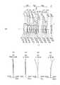
図1(a)〜図12(a)は、各実施例の単焦点光学系におけるレンズ断面図を示している。なお、レンズ断面図は、無限遠物体合焦時のレンズ断面図である。 Fig.1 (a)-FIG. 12 (a) have shown the lens sectional view in the single focus optical system of each Example. The lens sectional view is a lens sectional view at the time of focusing on an infinite distance object.
また、図1(b)〜図12(b)は、各実施例の単焦点光学系における球面収差(SA)を示し、図1(c)〜図12(c)は非点収差(AS)を示し、図1(d)〜図12(d)は歪曲収差(DT)を示し、図1(e)〜図12(e)は歪曲収差(DT)を示している。なお、各収差図は、無限遠物体合焦時の収差図である。また“ω”は半画角を表している。 Moreover, FIG.1 (b)-FIG.12 (b) show the spherical aberration (SA) in the single focus optical system of each Example, FIG.1 (c)-FIG.12 (c) are astigmatism (AS) 1 (d) to 12 (d) show distortion (DT), and FIGS. 1 (e) to 12 (e) show distortion (DT). Each aberration diagram is an aberration diagram at the time of focusing on an infinite distance object. “Ω” represents a half angle of view.
また、各実施例のレンズ断面図では、第1レンズ群をG1、第2レンズ群をG2、第3レンズ群をG3、カバーガラスをC、像面をIで示してある。 Further, in the lens sectional views of the respective embodiments, the first lens group is indicated by G1, the second lens group is indicated by G2, the third lens group is indicated by G3, the cover glass is indicated by C, and the image plane is indicated by I.
また、図示しないが、第3レンズ群G3と像面Iとの間に、ローパスフィルタを構成する平行平板が配置されていても良い。なお、平行平板の表面に、赤外光を制限する波長域制限コートを施しても良い。また、カバーガラスCの表面に波長域制限用の多層膜を施してもよい。また、そのカバーガラスCにローパスフィルタ作用を持たせるようにしてもよい。 Although not shown, a parallel flat plate constituting a low pass filter may be disposed between the third lens group G3 and the image plane I. The surface of the parallel flat plate may be provided with a wavelength range limiting coat for limiting infrared light. In addition, a multilayer film for wavelength range limitation may be provided on the surface of the cover glass C. Further, the cover glass C may have a low pass filter action.
また、単焦点光学系を撮像に用いる場合、像面Iには撮像素子が配置される。一方、単焦点光学系を投影に用いる場合、像面Iには表示素子が配置される。各実施例の構成の説明では、単焦点光学系を撮像に用いることを前提に説明する。よって、拡大側を物体側、縮小側を像側とする。 In addition, when using a single focus optical system for imaging, an imaging element is disposed on the image plane I. On the other hand, when a single focus optical system is used for projection, a display element is disposed on the image plane I. The configuration of each embodiment will be described on the assumption that a single focus optical system is used for imaging. Therefore, the enlargement side is the object side, and the reduction side is the image side.
実施例1に係る単焦点光学系について説明する。図1(a)は、実施例1に係る単焦点光学系のレンズ断面図である。図1(b)、(c)、(d)及び(e)は実施例1に係る単焦点光学系の収差図である。 The single-focus optical system according to the first embodiment will be described. FIG. 1A is a lens cross-sectional view of the single-focus optical system according to the first embodiment. FIGS. 1B, 1C, 1D, and 1E are aberration diagrams of the single-focus optical system according to Example 1. FIGS.
実施例1に係る単焦点光学系は、図1(a)に示すように、物体側から順に、負の屈折力を有する第1レンズ群G1と、正の屈折力を有する第2レンズ群G2と、正の屈折力を有する第3レンズ群G3と、で構成されている。第2レンズ群G2は開口絞りSを含んでいる。 As shown in FIG. 1A, the single-focus optical system according to the first embodiment includes, in order from the object side, a first lens group G1 having negative refractive power and a second lens group G2 having positive refractive power. And a third lens group G3 having a positive refractive power. The second lens group G2 includes an aperture stop S.
第1レンズ群G1は、物体側に凸面を向けた負メニスカスレンズL1と、両凸正レンズL2と、両凹負レンズL3と、で構成されている。ここで、両凸正レンズL2と両凹負レンズL3とが接合されている。 The first lens group G1 is composed of a negative meniscus lens L1 having a convex surface facing the object side, a biconvex positive lens L2, and a biconcave negative lens L3. Here, the biconvex positive lens L2 and the biconcave negative lens L3 are cemented.
第2レンズ群G2は、両凹負レンズL4と、両凸正レンズL5と、像側に凸面を向けた正メニスカスレンズL6と、両凸正レンズL7と、両凸正レンズL8と、で構成されている。ここで、両凹負レンズL4と両凸正レンズL5とが接合されている。 The second lens group G2 includes a biconcave negative lens L4, a biconvex positive lens L5, a positive meniscus lens L6 having a convex surface facing the image side, a biconvex positive lens L7, and a biconvex positive lens L8. It is done. Here, the biconcave negative lens L4 and the biconvex positive lens L5 are cemented.
第3レンズ群G3は、第1副群と、第2副群と、第3副群と、で構成されている。第1副群は、物体側に凸面を向けた負メニスカスレンズL9で構成されている。第2副群は、両凸正レンズL10で構成されている。第3副群は、両凸正レンズL11と、物体側に凸面を向けた負メニスカスレンズL12と、で構成されている。 The third lens group G3 is composed of a first sub group, a second sub group, and a third sub group. The first sub group is composed of a negative meniscus lens L9 having a convex surface facing the object side. The second sub group is composed of a biconvex positive lens L10. The third sub group includes a biconvex positive lens L11 and a negative meniscus lens L12 having a convex surface facing the object side.
また、無限遠物体から近距離物体への合焦時に、負メニスカスレンズL9が光軸に沿って像側へ移動する。 Further, at the time of focusing from an infinite distance object to a close distance object, the negative meniscus lens L9 moves to the image side along the optical axis.
非球面は、負メニスカスレンズL1の物体側面と、両凹負レンズL3の像側面と、負メニスカスレンズL9の両面と、両凸正レンズL10の像側面と、の合計5面に設けられている。 The aspheric surface is provided on a total of five surfaces: the object side surface of the negative meniscus lens L1, the image side surface of the biconcave negative lens L3, both surfaces of the negative meniscus lens L9, and the image side of the biconvex positive lens L10. .
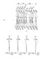
次に、実施例2に係る単焦点光学系について説明する。図2(a)は、実施例2に係る単焦点光学系のレンズ断面図である。図2(b)、(c)、(d)及び(e)は実施例2に係る単焦点光学系の収差図である。 Next, a single-focus optical system according to Example 2 will be described. FIG. 2A is a lens cross-sectional view of a single-focus optical system according to a second embodiment. FIGS. 2B, 2C, 2D, and 2E are aberration diagrams of the single-focus optical system according to Example 2. FIG.
実施例2に係る単焦点光学系は、図2(a)に示すように、物体側から順に、負の屈折力を有する第1レンズ群G1と、正の屈折力を有する第2レンズ群G2と、正の屈折力を有する第3レンズ群G3と、で構成されている。第2レンズ群G2は開口絞りSを含んでいる。 As shown in FIG. 2A, the single-focus optical system according to the second embodiment includes, in order from the object side, a first lens group G1 having negative refractive power and a second lens group G2 having positive refractive power. And a third lens group G3 having a positive refractive power. The second lens group G2 includes an aperture stop S.
第1レンズ群G1は、物体側に凸面を向けた負メニスカスレンズL1と、両凸正レンズL2と、両凹負レンズL3と、で構成されている。ここで、両凸正レンズL2と両凹負レンズL3とが接合されている。 The first lens group G1 is composed of a negative meniscus lens L1 having a convex surface facing the object side, a biconvex positive lens L2, and a biconcave negative lens L3. Here, the biconvex positive lens L2 and the biconcave negative lens L3 are cemented.
第2レンズ群G2は、両凹負レンズL4と、両凸正レンズL5と、両凸正レンズL6と、両凸正レンズL7と、物体側に凸面を向けた正メニスカスレンズL8と、で構成されている。ここで、両凹負レンズL4と両凸正レンズL5とが接合されている。 The second lens group G2 is composed of a biconcave negative lens L4, a biconvex positive lens L5, a biconvex positive lens L6, a biconvex positive lens L7, and a positive meniscus lens L8 having a convex surface facing the object side. It is done. Here, the biconcave negative lens L4 and the biconvex positive lens L5 are cemented.
第3レンズ群G3は、第1副群と、第2副群と、第3副群と、で構成されている。第1副群は、物体側に凸面を向けた負メニスカスレンズL9で構成されている。第2副群は、両凸正レンズL10で構成されている。第3副群は、両凸正レンズL11と、像側に凸面を向けた負メニスカスレンズL12と、で構成されている。 The third lens group G3 is composed of a first sub group, a second sub group, and a third sub group. The first sub group is composed of a negative meniscus lens L9 having a convex surface facing the object side. The second sub group is composed of a biconvex positive lens L10. The third sub group is composed of a biconvex positive lens L11 and a negative meniscus lens L12 having a convex surface facing the image side.
また、無限遠物体から近距離物体への合焦時に、負メニスカスレンズL9が光軸に沿って像側へ移動する。 Further, at the time of focusing from an infinite distance object to a close distance object, the negative meniscus lens L9 moves to the image side along the optical axis.
非球面は、負メニスカスレンズL1の両面と、負メニスカスレンズL9の両面と、の合計4面に設けられている。 Aspheric surfaces are provided on a total of four surfaces of both surfaces of the negative meniscus lens L1 and both surfaces of the negative meniscus lens L9.
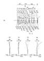
次に、実施例3に係る単焦点光学系について説明する。図3(a)は、実施例3に係る単焦点光学系のレンズ断面図である。図3(b)、(c)、(d)及び(e)は実施例3に係る単焦点光学系の収差図である。 Next, a single-focus optical system according to Example 3 will be described. FIG. 3A is a lens cross-sectional view of the single-focus optical system according to the third embodiment. FIGS. 3B, 3C, 3D, and 3E are aberration diagrams of the single-focus optical system according to Example 3. FIGS.
実施例3に係る単焦点光学系は、図3(a)に示すように、物体側から順に、負の屈折力を有する第1レンズ群G1と、正の屈折力を有する第2レンズ群G2と、正の屈折力を有する第3レンズ群G3と、で構成されている。第2レンズ群G2は開口絞りSを含んでいる。 As shown in FIG. 3A, the single-focus optical system according to the third embodiment includes, in order from the object side, a first lens group G1 having negative refractive power and a second lens group G2 having positive refractive power. And a third lens group G3 having a positive refractive power. The second lens group G2 includes an aperture stop S.
第1レンズ群G1は、物体側に凸面を向けた負メニスカスレンズL1と、物体側に凸面を向けた負メニスカスレンズL2と、両凸正レンズL3と、両凹負レンズL4と、で構成されている。ここで、負メニスカスレンズL2、両凸正レンズL3及び両凹負レンズL4が接合されている。 The first lens group G1 is composed of a negative meniscus lens L1 having a convex surface on the object side, a negative meniscus lens L2 having a convex surface on the object side, a biconvex positive lens L3, and a biconcave negative lens L4. ing. Here, the negative meniscus lens L2, the biconvex positive lens L3, and the biconcave negative lens L4 are cemented.
第2レンズ群G2は、両凹負レンズL5と、両凸正レンズL6と、像側に凸面を向けた正メニスカスレンズL7と、両凸正レンズL8と、物体側に凸面を向けた正メニスカスレンズL9と、で構成されている。ここで、両凹負レンズL5と両凸正レンズL6とが接合されている。 The second lens group G2 includes a biconcave negative lens L5, a biconvex positive lens L6, a positive meniscus lens L7 having a convex surface facing the image side, a biconvex positive lens L8, and a positive meniscus having a convex surface facing the object side And a lens L9. Here, the biconcave negative lens L5 and the biconvex positive lens L6 are cemented.
第3レンズ群G3は、第1副群と、第2副群と、第3副群と、で構成されている。第1副群は、物体側に凸面を向けた負メニスカスレンズL10で構成されている。第2副群は、両凸正レンズL11で構成されている。第3副群は、両凸正レンズL12と、両凸正レンズL13と、像側に凸面を向けた負メニスカスレンズL14と、で構成されている。 The third lens group G3 is composed of a first sub group, a second sub group, and a third sub group. The first sub group is composed of a negative meniscus lens L10 having a convex surface facing the object side. The second sub group is composed of a biconvex positive lens L11. The third sub group includes a biconvex positive lens L12, a biconvex positive lens L13, and a negative meniscus lens L14 having a convex surface directed toward the image side.
また、無限遠物体から近距離物体への合焦時に、負メニスカスレンズL10が光軸に沿って像側へ移動する。 In addition, at the time of focusing from an infinite distance object to a close distance object, the negative meniscus lens L10 moves to the image side along the optical axis.
非球面は、負メニスカスレンズL2の物体側面と、負メニスカスレンズL10の両面と、の合計3面に設けられている。 Aspheric surfaces are provided on a total of three surfaces of the object side surface of the negative meniscus lens L2 and both surfaces of the negative meniscus lens L10.
次に、実施例4に係る単焦点光学系について説明する。図4(a)は、実施例4に係る単焦点光学系のレンズ断面図である。図4(b)、(c)、(d)及び(e)は実施例4に係る単焦点光学系の収差図である。 Next, a single-focus optical system according to Example 4 will be described. FIG. 4A is a lens cross-sectional view of a single-focus optical system according to Example 4. FIG. FIGS. 4B, 4 C, 4 D, and 4 E are aberration diagrams of the single-focus optical system according to Example 4. FIGS.
実施例4に係る単焦点光学系は、図4(a)に示すように、物体側から順に、負の屈折力を有する第1レンズ群G1と、正の屈折力を有する第2レンズ群G2と、正の屈折力を有する第3レンズ群G3と、で構成されている。第2レンズ群G2は開口絞りSを含んでいる。 As shown in FIG. 4A, the single-focus optical system according to the fourth embodiment includes, in order from the object side, a first lens group G1 having negative refractive power and a second lens group G2 having positive refractive power. And a third lens group G3 having a positive refractive power. The second lens group G2 includes an aperture stop S.
第1レンズ群G1は、物体側に凸面を向けた負メニスカスレンズL1と、物体側に凸面を向けた負メニスカスレンズL2と、両凸正レンズL3と、両凹負レンズL4と、で構成されている。ここで、両凸正レンズL3と両凹負レンズL4とが接合されている。 The first lens group G1 is composed of a negative meniscus lens L1 having a convex surface on the object side, a negative meniscus lens L2 having a convex surface on the object side, a biconvex positive lens L3, and a biconcave negative lens L4. ing. Here, the biconvex positive lens L3 and the biconcave negative lens L4 are cemented.
第2レンズ群G2は、両凹負レンズL5と、両凸正レンズL6と、両凸正レンズL7と、物体側に凸面を向けた正メニスカスレンズL8と、で構成されている。ここで、両凹負レンズL5と両凸正レンズL6とが接合されている。 The second lens group G2 is composed of a biconcave negative lens L5, a biconvex positive lens L6, a biconvex positive lens L7, and a positive meniscus lens L8 having a convex surface facing the object side. Here, the biconcave negative lens L5 and the biconvex positive lens L6 are cemented.
第3レンズ群G3は、第1副群と、第2副群と、第3副群と、で構成されている。第1副群は、物体側に凸面を向けた負メニスカスレンズL9で構成されている。第2副群は、両凸正レンズL10で構成されている。第3副群は、両凸正レンズL11と、両凹負レンズL12と、物体側に凸面を向けた正メニスカスレンズL13と、で構成されている。ここで、両凸正レンズL11と両凹負レンズL12とが接合されている。 The third lens group G3 is composed of a first sub group, a second sub group, and a third sub group. The first sub group is composed of a negative meniscus lens L9 having a convex surface facing the object side. The second sub group is composed of a biconvex positive lens L10. The third sub group includes a biconvex positive lens L11, a biconcave negative lens L12, and a positive meniscus lens L13 having a convex surface facing the object side. Here, the biconvex positive lens L11 and the biconcave negative lens L12 are cemented.
また、無限遠物体から近距離物体への合焦時に、負メニスカスレンズL9が光軸に沿って像側へ移動する。 Further, at the time of focusing from an infinite distance object to a close distance object, the negative meniscus lens L9 moves to the image side along the optical axis.
非球面は、負メニスカスレンズL2の両面と、負メニスカスレンズL9の両面と、の合計4面に設けられている。 Aspheric surfaces are provided on a total of four surfaces of both surfaces of the negative meniscus lens L2 and both surfaces of the negative meniscus lens L9.
次に、実施例5に係る単焦点光学系について説明する。図5(a)は、実施例5に係る単焦点光学系のレンズ断面図である。図5(b)、(c)、(d)及び(e)は実施例5に係る単焦点光学系の収差図である。 Next, a single-focus optical system according to Example 5 will be described. FIG. 5A is a lens cross-sectional view of a single-focus optical system according to Example 5. FIG. FIGS. 5B, 5C, 5D, and 5E are aberration diagrams of the single-focus optical system according to Example 5. FIGS.
実施例5に係る単焦点光学系は、図5(a)に示すように、物体側から順に、負の屈折力を有する第1レンズ群G1と、正の屈折力を有する第2レンズ群G2と、正の屈折力を有する第3レンズ群G3と、で構成されている。第2レンズ群G2は開口絞りSを含んでいる。 As shown in FIG. 5A, the single-focus optical system according to the fifth embodiment includes, in order from the object side, a first lens group G1 having negative refractive power and a second lens group G2 having positive refractive power. And a third lens group G3 having a positive refractive power. The second lens group G2 includes an aperture stop S.
第1レンズ群G1は、物体側に凸面を向けた負メニスカスレンズL1と、物体側に凸面を向けた負メニスカスレンズL2と、両凸正レンズL3と、両凹負レンズL4と、で構成されている。ここで、両凸正レンズL3と両凹負レンズL4とが接合されている。 The first lens group G1 is composed of a negative meniscus lens L1 having a convex surface on the object side, a negative meniscus lens L2 having a convex surface on the object side, a biconvex positive lens L3, and a biconcave negative lens L4. ing. Here, the biconvex positive lens L3 and the biconcave negative lens L4 are cemented.
第2レンズ群G2は、両凹負レンズL5と、両凸正レンズL6と、両凸正レンズL7と、物体側に凸面を向けた正メニスカスレンズL8と、で構成されている。ここで、両凹負レンズL5と両凸正レンズL6とが接合されている。 The second lens group G2 is composed of a biconcave negative lens L5, a biconvex positive lens L6, a biconvex positive lens L7, and a positive meniscus lens L8 having a convex surface facing the object side. Here, the biconcave negative lens L5 and the biconvex positive lens L6 are cemented.
第3レンズ群G3は、第1副群と、第2副群と、第3副群と、で構成されている。第1副群は、物体側に凸面を向けた負メニスカスレンズL9で構成されている。第2副群は、両凸正レンズL10で構成されている。第3副群は、両凸正レンズL11と、両凹負レンズL12と、物体側に凸面を向けた正メニスカスレンズL13と、で構成されている。ここで、両凸正レンズL11と両凹負レンズL12とが接合されている。 The third lens group G3 is composed of a first sub group, a second sub group, and a third sub group. The first sub group is composed of a negative meniscus lens L9 having a convex surface facing the object side. The second sub group is composed of a biconvex positive lens L10. The third sub group includes a biconvex positive lens L11, a biconcave negative lens L12, and a positive meniscus lens L13 having a convex surface facing the object side. Here, the biconvex positive lens L11 and the biconcave negative lens L12 are cemented.
また、無限遠物体から近距離物体への合焦時に、負メニスカスレンズL9が光軸に沿って像側へ移動する。 Further, at the time of focusing from an infinite distance object to a close distance object, the negative meniscus lens L9 moves to the image side along the optical axis.
非球面は、負メニスカスレンズL2の両面と、負メニスカスレンズL9の両面と、の合計4面に設けられている。 Aspheric surfaces are provided on a total of four surfaces of both surfaces of the negative meniscus lens L2 and both surfaces of the negative meniscus lens L9.
次に、実施例6に係る単焦点光学系について説明する。図6(a)は、実施例6に係る単焦点光学系のレンズ断面図である。図6(b)、(c)、(d)及び(e)は実施例6に係る単焦点光学系の収差図である。 Next, a single-focus optical system according to Example 6 will be described. FIG. 6A is a lens cross-sectional view of a single-focus optical system according to a sixth embodiment. 6 (b), (c), (d) and (e) are aberration diagrams of the single-focus optical system according to Example 6. FIG.
実施例6に係る単焦点光学系は、図6(a)に示すように、物体側から順に、負の屈折力を有する第1レンズ群G1と、正の屈折力を有する第2レンズ群G2と、正の屈折力を有する第3レンズ群G3と、で構成されている。第2レンズ群G2は開口絞りSを含んでいる。 The single-focus optical system according to Example 6 includes, in order from the object side, a first lens group G1 having negative refractive power and a second lens group G2 having positive refractive power, as shown in FIG. 6A. And a third lens group G3 having a positive refractive power. The second lens group G2 includes an aperture stop S.
第1レンズ群G1は、物体側に凸面を向けた負メニスカスレンズL1と、物体側に凸面を向けた負メニスカスレンズL2と、両凸正レンズL3と、両凹負レンズL4と、で構成されている。ここで、両凸正レンズL3と両凹負レンズL4とが接合されている。 The first lens group G1 is composed of a negative meniscus lens L1 having a convex surface on the object side, a negative meniscus lens L2 having a convex surface on the object side, a biconvex positive lens L3, and a biconcave negative lens L4. ing. Here, the biconvex positive lens L3 and the biconcave negative lens L4 are cemented.
第2レンズ群G2は、両凹負レンズL5と、両凸正レンズL6と、両凸正レンズL7と、両凸正レンズL8と、で構成されている。ここで、両凹負レンズL5と両凸正レンズL6とが接合されている。 The second lens group G2 is composed of a biconcave negative lens L5, a biconvex positive lens L6, a biconvex positive lens L7, and a biconvex positive lens L8. Here, the biconcave negative lens L5 and the biconvex positive lens L6 are cemented.
第3レンズ群G3は、第1副群と、第2副群と、第3副群と、で構成されている。第1副群は、物体側に凸面を向けた負メニスカスレンズL9で構成されている。第2副群は、両凸正レンズL10で構成されている。第3副群は、両凸正レンズL11と、両凹負レンズL12と、物体側に凸面を向けた正メニスカスレンズL13と、で構成されている。ここで、両凸正レンズL11と両凹負レンズL12とが接合されている。 The third lens group G3 is composed of a first sub group, a second sub group, and a third sub group. The first sub group is composed of a negative meniscus lens L9 having a convex surface facing the object side. The second sub group is composed of a biconvex positive lens L10. The third sub group includes a biconvex positive lens L11, a biconcave negative lens L12, and a positive meniscus lens L13 having a convex surface facing the object side. Here, the biconvex positive lens L11 and the biconcave negative lens L12 are cemented.
また、無限遠物体から近距離物体への合焦時に、負メニスカスレンズL9が光軸に沿って像側へ移動する。 Further, at the time of focusing from an infinite distance object to a close distance object, the negative meniscus lens L9 moves to the image side along the optical axis.
非球面は、負メニスカスレンズL2の両面と、負メニスカスレンズL9の両面と、の合計4面に設けられている。 Aspheric surfaces are provided on a total of four surfaces of both surfaces of the negative meniscus lens L2 and both surfaces of the negative meniscus lens L9.
次に、実施例7に係る単焦点光学系について説明する。図7(a)は、実施例7に係る単焦点光学系のレンズ断面図である。図7(b)、(c)、(d)及び(e)は実施例7に係る単焦点光学系の収差図である。 Next, a single-focus optical system according to Example 7 will be described. FIG. 7A is a lens cross-sectional view of a single focus optical system according to a seventh example. FIGS. 7B, 7 C, 7 D and 7 E are aberration diagrams of the single focal point optical system according to Example 7. FIGS.
実施例7に係る単焦点光学系は、図7(a)に示すように、物体側から順に、負の屈折力を有する第1レンズ群G1と、正の屈折力を有する第2レンズ群G2と、正の屈折力を有する第3レンズ群G3と、で構成されている。第2レンズ群G2は開口絞りSを含んでいる。 As shown in FIG. 7A, the single-focus optical system according to Example 7 includes, in order from the object side, a first lens group G1 having negative refractive power and a second lens group G2 having positive refractive power. And a third lens group G3 having a positive refractive power. The second lens group G2 includes an aperture stop S.
第1レンズ群G1は、物体側に凸面を向けた負メニスカスレンズL1と、物体側に凸面を向けた正メニスカスレンズL2と、物体側に凸面を向けた正メニスカスレンズL3と、物体側に凸面を向けた負メニスカスレンズL4と、で構成されている。ここで、正メニスカスレンズL3と負メニスカスレンズL4とが接合されている。 The first lens group G1 has a negative meniscus lens L1 having a convex surface on the object side, a positive meniscus lens L2 having a convex surface on the object side, a positive meniscus lens L3 having a convex surface on the object side, and a convex surface on the object side And a negative meniscus lens L4 facing the lens. Here, the positive meniscus lens L3 and the negative meniscus lens L4 are cemented.
第2レンズ群G2は、両凹負レンズL5と、両凸正レンズL6と、両凸正レンズL7と、物体側に凸面を向けた正メニスカスレンズL8と、で構成されている。ここで、両凹負レンズL5と両凸正レンズL6とが接合されている。 The second lens group G2 is composed of a biconcave negative lens L5, a biconvex positive lens L6, a biconvex positive lens L7, and a positive meniscus lens L8 having a convex surface facing the object side. Here, the biconcave negative lens L5 and the biconvex positive lens L6 are cemented.
第3レンズ群G3は、第1副群と、第2副群と、第3副群と、で構成されている。第1副群は、物体側に凸面を向けた負メニスカスレンズL9で構成されている。第2副群は、像側に凸面を向けた正メニスカスレンズL10で構成されている。第3副群は、両凸正レンズL11と、両凹負レンズL12と、両凸正レンズL13と、で構成されている。ここで、両凸正レンズL11と両凹負レンズL12とが接合されている。 The third lens group G3 is composed of a first sub group, a second sub group, and a third sub group. The first sub group is composed of a negative meniscus lens L9 having a convex surface facing the object side. The second sub group includes a positive meniscus lens L10 having a convex surface facing the image side. The third sub group includes a biconvex positive lens L11, a biconcave negative lens L12, and a biconvex positive lens L13. Here, the biconvex positive lens L11 and the biconcave negative lens L12 are cemented.
また、無限遠物体から近距離物体への合焦時に、負メニスカスレンズL9が光軸に沿って像側へ移動する。 Further, at the time of focusing from an infinite distance object to a close distance object, the negative meniscus lens L9 moves to the image side along the optical axis.
非球面は、負メニスカスレンズL9の両面に設けられている。 Aspheric surfaces are provided on both surfaces of the negative meniscus lens L9.
次に、実施例8に係る単焦点光学系について説明する。図8(a)は、実施例8に係る単焦点光学系のレンズ断面図である。図8(b)、(c)、(d)及び(e)は実施例8に係る単焦点光学系の収差図である。 Next, a single-focus optical system according to Example 8 will be described. FIG. 8A is a lens cross-sectional view of the single-focus optical system according to Example 8. FIG. FIGS. 8B, 8C, 8D, and 8E are aberration diagrams of the single-focus optical system according to Example 8. FIGS.
実施例8に係る単焦点光学系は、図8(a)に示すように、物体側から順に、負の屈折力を有する第1レンズ群G1と、正の屈折力を有する第2レンズ群G2と、正の屈折力を有する第3レンズ群G3と、で構成されている。第2レンズ群G2は開口絞りSを含んでいる。 As shown in FIG. 8A, the single-focus optical system according to Example 8 includes, in order from the object side, a first lens group G1 having negative refractive power, and a second lens group G2 having positive refractive power. And a third lens group G3 having a positive refractive power. The second lens group G2 includes an aperture stop S.
第1レンズ群G1は、物体側に凸面を向けた負メニスカスレンズL1と、物体側に凸面を向けた負メニスカスレンズL2と、両凸正レンズL3と、両凹負レンズL4と、で構成されている。ここで、両凸正レンズL3と両凹負レンズL4とが接合されている。 The first lens group G1 is composed of a negative meniscus lens L1 having a convex surface on the object side, a negative meniscus lens L2 having a convex surface on the object side, a biconvex positive lens L3, and a biconcave negative lens L4. ing. Here, the biconvex positive lens L3 and the biconcave negative lens L4 are cemented.
第2レンズ群G2は、両凹負レンズL5と、両凸正レンズL6と、両凸正レンズL7と、両凸正レンズL8と、で構成されている。ここで、両凹負レンズL5と両凸正レンズL6とが接合されている。 The second lens group G2 is composed of a biconcave negative lens L5, a biconvex positive lens L6, a biconvex positive lens L7, and a biconvex positive lens L8. Here, the biconcave negative lens L5 and the biconvex positive lens L6 are cemented.
第3レンズ群G3は、第1副群と、第2副群と、第3副群と、で構成されている。第1副群は、物体側に凸面を向けた負メニスカスレンズL9で構成されている。第2副群は、両凸正レンズL10で構成されている。第3副群は、両凹負レンズL11と、両凸正レンズL12と、で構成されている。ここで、両凹負レンズL11と両凸正レンズL12とが接合されている。 The third lens group G3 is composed of a first sub group, a second sub group, and a third sub group. The first sub group is composed of a negative meniscus lens L9 having a convex surface facing the object side. The second sub group is composed of a biconvex positive lens L10. The third sub group includes a biconcave negative lens L11 and a biconvex positive lens L12. Here, the biconcave negative lens L11 and the biconvex positive lens L12 are cemented.
また、無限遠物体から近距離物体への合焦時に、負メニスカスレンズL9が光軸に沿って像側へ移動すると共に、両凸正レンズL10が光軸に沿って物体側に移動する。 Further, at the time of focusing from an infinite distance object to a close distance object, the negative meniscus lens L9 moves to the image side along the optical axis, and the biconvex positive lens L10 moves to the object side along the optical axis.
非球面は、負メニスカスレンズL2の両面と、負メニスカスレンズL9の両面と、両凸正レンズL10両面と、の合計6面に設けられている。 Aspheric surfaces are provided on a total of six surfaces: both surfaces of the negative meniscus lens L2, both surfaces of the negative meniscus lens L9, and both surfaces of the biconvex positive lens L10.
次に、実施例9に係る単焦点光学系について説明する。図9(a)は、実施例9に係る単焦点光学系のレンズ断面図である。図9(b)、(c)、(d)及び(e)は実施例9に係る単焦点光学系の収差図である。 Next, a single-focus optical system according to Example 9 will be described. FIG. 9A is a lens cross-sectional view of a single-focus optical system according to Example 9. FIG. FIGS. 9B, 9C, 9D, and 9E are aberration diagrams of the single-focus optical system according to Example 9. FIGS.
実施例9に係る単焦点光学系は、図9(a)に示すように、物体側から順に、負の屈折力を有する第1レンズ群G1と、正の屈折力を有する第2レンズ群G2と、正の屈折力を有する第3レンズ群G3と、で構成されている。第2レンズ群G2は開口絞りSを含んでいる。 As shown in FIG. 9A, the single-focus optical system according to Example 9 includes, in order from the object side, a first lens group G1 having negative refractive power and a second lens group G2 having positive refractive power. And a third lens group G3 having a positive refractive power. The second lens group G2 includes an aperture stop S.
第1レンズ群G1は、物体側に凸面を向けた負メニスカスレンズL1と、物体側に凸面を向けた負メニスカスレンズL2と、両凸正レンズL3と、両凹負レンズL4と、で構成されている。ここで、両凸正レンズL3と両凹負レンズL4とが接合されている。 The first lens group G1 is composed of a negative meniscus lens L1 having a convex surface on the object side, a negative meniscus lens L2 having a convex surface on the object side, a biconvex positive lens L3, and a biconcave negative lens L4. ing. Here, the biconvex positive lens L3 and the biconcave negative lens L4 are cemented.
第2レンズ群G2は、両凹負レンズL5と、両凸正レンズL6と、両凸正レンズL7と、物体側に凸面を向けた正メニスカスレンズL8と、で構成されている。ここで、両凹負レンズL5と両凸正レンズL6とが接合されている。 The second lens group G2 is composed of a biconcave negative lens L5, a biconvex positive lens L6, a biconvex positive lens L7, and a positive meniscus lens L8 having a convex surface facing the object side. Here, the biconcave negative lens L5 and the biconvex positive lens L6 are cemented.
第3レンズ群G3は、第1副群と、第2副群と、第3副群と、で構成されている。第1副群は、物体側に凸面を向けた負メニスカスレンズL9で構成されている。第2副群は、両凸正レンズL10で構成されている。第3副群は、物体側に凸面を向けた負メニスカスレンズL11と、両凸正レンズL12と、で構成されている。ここで、負メニスカスレンズL11と両凸正レンズL12とが接合されている。 The third lens group G3 is composed of a first sub group, a second sub group, and a third sub group. The first sub group is composed of a negative meniscus lens L9 having a convex surface facing the object side. The second sub group is composed of a biconvex positive lens L10. The third sub group includes a negative meniscus lens L11 with a convex surface facing the object side, and a biconvex positive lens L12. Here, the negative meniscus lens L11 and the biconvex positive lens L12 are cemented.
また、無限遠物体から近距離物体への合焦時に、負メニスカスレンズL9が光軸に沿って像側へ移動すると共に、両凸正レンズL10が光軸に沿って物体側に移動する。 Further, at the time of focusing from an infinite distance object to a close distance object, the negative meniscus lens L9 moves to the image side along the optical axis, and the biconvex positive lens L10 moves to the object side along the optical axis.
非球面は、負メニスカスレンズL9の両面と、両凸正レンズL10両面と、の合計4面に設けられている。 Aspheric surfaces are provided on a total of four surfaces of both surfaces of the negative meniscus lens L9 and both surfaces of the biconvex positive lens L10.
次に、実施例10に係る単焦点光学系について説明する。図10(a)は、実施例10に係る単焦点光学系のレンズ断面図である。図10(b)、(c)、(d)及び(e)は実施例10に係る単焦点光学系の収差図である。
実施例10に係る単焦点光学系は、図10(a)に示すように、物体側から順に、負の屈折力を有する第1レンズ群G1と、正の屈折力を有する第2レンズ群G2と、正の屈折力を有する第3レンズ群G3と、で構成されている。第2レンズ群G2は開口絞りSを含んでいる。Next, a single-focus optical system according to Example 10 will be described. FIG. 10A is a lens cross-sectional view of the single-focus optical system according to Example 10. FIG. FIGS. 10 (b), (c), (d) and (e) are aberration diagrams of the single-focus optical system according to Example 10. FIGS.
As shown in FIG. 10A, the single-focus optical system according to Example 10 includes, in order from the object side, a first lens group G1 having negative refractive power and a second lens group G2 having positive refractive power. And a third lens group G3 having a positive refractive power. The second lens group G2 includes an aperture stop S.
第1レンズ群G1は、物体側に凸面を向けた負メニスカスレンズL1と、物体側に凸面を向けた正メニスカスレンズL2と、物体側に凸面を向けた正メニスカスレンズL3と、物体側に凸面を向けた負メニスカスレンズL4と、で構成されている。ここで、正メニスカスレンズL3と負メニスカスレンズL4とが接合されている。 The first lens group G1 has a negative meniscus lens L1 having a convex surface on the object side, a positive meniscus lens L2 having a convex surface on the object side, a positive meniscus lens L3 having a convex surface on the object side, and a convex surface on the object side And a negative meniscus lens L4 facing the lens. Here, the positive meniscus lens L3 and the negative meniscus lens L4 are cemented.
第2レンズ群G2は、両凹負レンズL5と、両凸正レンズL6と、像側に凸面を向けた正メニスカスレンズL7と、両凸正レンズL8と、で構成されている。ここで、両凹負レンズL5と両凸正レンズL6とが接合されている。 The second lens group G2 is composed of a biconcave negative lens L5, a biconvex positive lens L6, a positive meniscus lens L7 having a convex surface facing the image side, and a biconvex positive lens L8. Here, the biconcave negative lens L5 and the biconvex positive lens L6 are cemented.
第3レンズ群G3は、第1副群と、第2副群と、第3副群と、で構成されている。第1副群は、物体側に凸面を向けた負メニスカスレンズL9で構成されている。第2副群は、両凸正レンズL10で構成されている。第3副群は、両凹負レンズL11と、両凸正レンズL12と、で構成されている。ここで、両凹負レンズL11と両凸正レンズL12とが接合されている。 The third lens group G3 is composed of a first sub group, a second sub group, and a third sub group. The first sub group is composed of a negative meniscus lens L9 having a convex surface facing the object side. The second sub group is composed of a biconvex positive lens L10. The third sub group includes a biconcave negative lens L11 and a biconvex positive lens L12. Here, the biconcave negative lens L11 and the biconvex positive lens L12 are cemented.
また、無限遠物体から近距離物体への合焦時に、負メニスカスレンズL9が光軸に沿って像側へ移動すると共に、両凸正レンズL10が光軸に沿って物体側に移動する。 Further, at the time of focusing from an infinite distance object to a close distance object, the negative meniscus lens L9 moves to the image side along the optical axis, and the biconvex positive lens L10 moves to the object side along the optical axis.
非球面は、負メニスカスレンズL9の両面と、両凸正レンズL10両面と、の合計4面に設けられている。 Aspheric surfaces are provided on a total of four surfaces of both surfaces of the negative meniscus lens L9 and both surfaces of the biconvex positive lens L10.
次に、実施例11に係る単焦点光学系について説明する。図11(a)は、実施例11に係る単焦点光学系のレンズ断面図である。図11(b)、(c)、(d)及び(e)は実施例11に係る単焦点光学系の収差図である。 Next, a single-focus optical system according to Example 11 will be described. FIG. 11A is a lens cross-sectional view of a single-focus optical system according to Example 11. FIG. FIGS. 11 (b), (c), (d) and (e) are aberration diagrams of the single-focus optical system according to Example 11. FIGS.
実施例11に係る単焦点光学系は、図11(a)に示すように、物体側から順に、負の屈折力を有する第1レンズ群G1と、正の屈折力を有する第2レンズ群G2と、正の屈折力を有する第3レンズ群G3と、で構成されている。第2レンズ群G2は開口絞りSを含んでいる。 As shown in FIG. 11A, the single-focus optical system according to Example 11 includes, in order from the object side, a first lens group G1 having negative refractive power, and a second lens group G2 having positive refractive power. And a third lens group G3 having a positive refractive power. The second lens group G2 includes an aperture stop S.
第1レンズ群G1は、物体側に凸面を向けた負メニスカスレンズL1と、物体側に凸面を向けた負メニスカスレンズL2と、両凸正レンズL3と、両凹負レンズL4と、で構成されている。ここで、両凸正レンズL3と両凹負レンズL4とが接合されている。 The first lens group G1 is composed of a negative meniscus lens L1 having a convex surface on the object side, a negative meniscus lens L2 having a convex surface on the object side, a biconvex positive lens L3, and a biconcave negative lens L4. ing. Here, the biconvex positive lens L3 and the biconcave negative lens L4 are cemented.
第2レンズ群G2は、両凹負レンズL5と、両凸正レンズL6と、両凸正レンズL7と、両凸正レンズL8と、像側に凸面を向けた負メニスカスレンズL9と、で構成されている。ここで、両凹負レンズL5と両凸正レンズL6とが接合されている。また、両凸正レンズL8と負メニスカスレンズL9とが接合されている。 The second lens group G2 is composed of a biconcave negative lens L5, a biconvex positive lens L6, a biconvex positive lens L7, a biconvex positive lens L8, and a negative meniscus lens L9 having a convex surface facing the image side. It is done. Here, the biconcave negative lens L5 and the biconvex positive lens L6 are cemented. Further, the biconvex positive lens L8 and the negative meniscus lens L9 are cemented.
第3レンズ群G3は、第1副群と、第2副群と、第3副群と、で構成されている。第1副群は、物体側に凸面を向けた負メニスカスレンズL10で構成されている。第2副群は、物体側に凸面を向けた負メニスカスレンズL11と、両凸正レンズL12と、で構成されている。第3副群は、像側に凸面を向けた負メニスカスレンズL13と、で構成されている。ここで、負メニスカスレンズL11と両凸正レンズL12とが接合されている。 The third lens group G3 is composed of a first sub group, a second sub group, and a third sub group. The first sub group is composed of a negative meniscus lens L10 having a convex surface facing the object side. The second sub group includes a negative meniscus lens L11 with a convex surface facing the object side, and a biconvex positive lens L12. The third sub group includes a negative meniscus lens L13 having a convex surface facing the image side. Here, the negative meniscus lens L11 and the biconvex positive lens L12 are cemented.
また、無限遠物体から近距離物体への合焦時に、負メニスカスレンズL10が光軸に沿って像側へ移動すると共に、負メニスカスレンズL11と両凸正レンズL12とが光軸に沿って物体側に移動する。 Further, at the time of focusing from an infinite distance object to a close distance object, the negative meniscus lens L10 moves to the image side along the optical axis, and the negative meniscus lens L11 and the biconvex positive lens L12 move along the optical axis. Move to the side.
非球面は、負メニスカスレンズL2の両面と、負メニスカスレンズL10の両面と、両凸正レンズL12の像側面と、の合計5面に設けられている。 Aspheric surfaces are provided on five surfaces in total: both surfaces of the negative meniscus lens L2, both surfaces of the negative meniscus lens L10, and the image side surface of the biconvex positive lens L12.
次に、実施例12に係る単焦点光学系について説明する。図12(a)は、実施例12に係る単焦点光学系のレンズ断面図である。図12(b)、(c)、(d)及び(e)は実施例12に係る単焦点光学系の収差図である。 Next, a single-focus optical system according to Example 12 will be described. FIG. 12A is a lens cross-sectional view of a single-focus optical system according to Example 12. FIG. 12B, 12C, 12D, and 12E are aberration diagrams of the single-focus optical system according to Example 12. FIG.
実施例12に係る単焦点光学系は、図12(a)に示すように、物体側から順に、負の屈折力を有する第1レンズ群G1と、正の屈折力を有する第2レンズ群G2と、正の屈折力を有する第3レンズ群G3と、で構成されている。第2レンズ群G2は開口絞りSを含んでいる。 As shown in FIG. 12A, the single-focus optical system according to Example 12 includes, in order from the object side, a first lens group G1 having negative refractive power and a second lens group G2 having positive refractive power. And a third lens group G3 having a positive refractive power. The second lens group G2 includes an aperture stop S.
第1レンズ群G1は、物体側に凸面を向けた負メニスカスレンズL1と、物体側に凸面を向けた負メニスカスレンズL2と、両凸正レンズL3と、両凹負レンズL4と、で構成されている。ここで、両凸正レンズL3と両凹負レンズL4とが接合されている。 The first lens group G1 is composed of a negative meniscus lens L1 having a convex surface on the object side, a negative meniscus lens L2 having a convex surface on the object side, a biconvex positive lens L3, and a biconcave negative lens L4. ing. Here, the biconvex positive lens L3 and the biconcave negative lens L4 are cemented.
第2レンズ群G2は、両凹負レンズL5と、両凸正レンズL6と、両凸正レンズL7と、両凸正レンズL8と、像側に凸面を向けた負メニスカスレンズL9と、で構成されている。ここで、両凹負レンズL5と両凸正レンズL6とが接合されている。また、両凸正レンズL8と負メニスカスレンズL9とが接合されている。 The second lens group G2 is composed of a biconcave negative lens L5, a biconvex positive lens L6, a biconvex positive lens L7, a biconvex positive lens L8, and a negative meniscus lens L9 having a convex surface facing the image side. It is done. Here, the biconcave negative lens L5 and the biconvex positive lens L6 are cemented. Further, the biconvex positive lens L8 and the negative meniscus lens L9 are cemented.
第3レンズ群G3は、第1副群と、第2副群と、第3副群と、で構成されている。第1副群は、両凹負レンズL10と、物体側に凸面を向けた負メニスカスレンズL11と、で構成されている。第2副群は、両凸正レンズL12で構成されている。第3副群は、両凹負レンズL13で構成されている。ここで、両凹負レンズL10と負メニスカスレンズL11とが接合されている。 The third lens group G3 is composed of a first sub group, a second sub group, and a third sub group. The first sub group is composed of a biconcave negative lens L10 and a negative meniscus lens L11 having a convex surface facing the object side. The second sub group is composed of a biconvex positive lens L12. The third sub group includes a biconcave negative lens L13. Here, the biconcave negative lens L10 and the negative meniscus lens L11 are cemented.
また、無限遠物体から近距離物体への合焦時に、両凹負レンズL10と負メニスカスレンズL11とが光軸に沿って像側へ移動する共に、両凸正レンズL12とが光軸に沿って物体側に移動する。 Further, when focusing from an infinite distance object to a near distance object, the biconcave negative lens L10 and the negative meniscus lens L11 move to the image side along the optical axis, and the biconvex positive lens L12 moves along the optical axis Move to the object side.
非球面は、負メニスカスレンズL2の両面と、両凹負レンズL10の物体側面と、負メニスカスレンズL11の像側面と、両凸正レンズL12の両面と、の合計6面に設けられている。 Aspheric surfaces are provided on a total of six surfaces: both surfaces of the negative meniscus lens L2, the object side surface of the biconcave negative lens L10, the image side surface of the negative meniscus lens L11, and both surfaces of the biconvex positive lens L12.
次に、上記各実施例の単焦点光学系を構成する光学部材の数値データを掲げる。なお、各実施例の数値データにおいて、r1、r2、…は各レンズ面の曲率半径、d1、d2、…は各レンズの肉厚または空気間隔、nd1、nd2、…は各レンズのd線での屈折率、νd1、νd2、…は各レンズのアッベ数、*印は非球面である。また、各種データにおいて、fは単焦点光学系全系の焦点距離、FNO.はFナンバー、ωは半画角、IHは像高、FBはバックフォーカス、f1、f2…は各レンズ群の焦点距離である。なお、全長は、レンズ最前面からレンズ最終面までの距離にバックフォーカスを加えたものである。バックフォーカスは、レンズ最終面から近軸像面までの距離を空気換算して表したものである。また、角度の単位は°(度)である。また、無限遠は無限遠物体合焦時、近距離は近距離物体合焦時を表す。また、近距離における値は、物体から像までの距離である。 Next, numerical data of optical members constituting the single-focus optical system of each of the above embodiments will be listed. In the numerical data of each example,
また、非球面形状は、光軸方向をz、光軸に直交する方向をyにとり、円錐係数をk、非球面係数をA4、A6、A8、A10としたとき、次の式で表される。
z=(y2/r)/[1+{1−(1+k)(y/r)2}1/2]
+A4y4+A6y6+A8y8+A10y10
また、非球面係数において、「e−n」(nは整数)は、「10−n」を示している。なお、これら諸元値の記号は後述の実施例の数値データにおいても共通である。Further, the aspheric surface shape is expressed by the following equation, assuming that the optical axis direction is z and the direction orthogonal to the optical axis is y, the conical coefficient is k, and the aspheric coefficient is A4, A6, A8, and A10. .
z = (y2 / r) / [1+ {1- (1 + k) (y / r)2 }1/2 ]
+ A4y4 + A6y6 + A8y8 + A10y10
Also, in the aspheric coefficients, "e-n" (n is an integer) indicates "10-n ". The symbols of these specification values are common to the numerical data of the embodiments described later.
数値実施例1
単位 mm
面データ
面番号 r d nd νd
物面 ∞ ∞
1* 88.390 1.50 1.58313 59.38
2 18.061 3.03
3 37.369 5.62 2.00069 25.46
4 -34.405 1.00 1.80610 40.92
5* 21.776 6.79
6 -13.943 1.20 1.80518 25.42
7 104.914 5.50 1.72916 54.68
8 -23.818 0.40
9 -51.466 3.06 2.00100 29.13
10 -27.493 0.40
11 456.546 3.21 1.72916 54.68
12 -54.882 0.60
13(絞り) ∞ 0.60
14 31.746 6.64 1.43875 94.93
15 -57.403 可変
16* 55.821 1.20 1.88202 37.22
17* 21.400 可変
18 58.597 7.89 1.49700 81.61
19* -22.104 0.40
20 53.129 6.95 1.65160 58.55
21 -157.363 0.40
22 46.040 1.50 1.84666 23.78
23 25.000 13.44
24 ∞ 2.66 1.51633 64.14
25 ∞ 1.00
像面 ∞
非球面データ
第1面
k=0.000
A4=1.39089e-05,A6=-3.51071e-08,A8=3.62113e-11
第5面
k=2.001
A4=9.68258e-06,A6=-1.18998e-08,A8=-7.24540e-10
第16面
k=0.000
A4=-2.43484e-05,A6=3.04464e-08,A8=-1.53837e-11
第17面
k=0.000
A4=-1.81003e-05,A6=8.23510e-09,A8=-2.70354e-11,A10=2.00162e-14
第19面
k=0.000
A4=1.70588e-05,A6=-1.01511e-08,A8=4.76074e-11
各種データ
f 17.27
FNO. 1.28
2ω 72.91
IH 11.15
FB(in air) 16.19
全長(in air) 85.58
無限遠 近距離
d15 2.60 5.50
d17 8.90 6.01
各群焦点距離
f1=-33.42 f2=21.08 f3=53.56
Unit mm
Surface data surface number rd nd d d
Object ∞ ∞
1 * 88.390 1.50 1.58313 59.38
2 18.061 3.03
3 37.369 5.62 2.00069 25.46
4-34.405 1.00 1.80610 40.92
5 * 21.776 6.79
6-13.943 1.20 1.80518 25.42
7 104.914 5.50 1.72916 54.68
8-23.818 0.40
9-51.466 3.06 2.00100 29.13
10-27. 493 0.40
11 456.546 3.21 1.72916 54.68
12-54. 882 0.60
13 (F-stop) ∞ 0.60
14 31.746 6.64 1.43875 94.93
15 -57.403 Variable
16 * 55.821 1.20 1.88202 37.22
17 * 21.400 variable
18 58.597 7.89 1.49700 81.61
19 * -22.104 0.40
20 53.129 6.95 1.65160 58.55
21 -157.363 0.40
22 46.040 1.50 1.84666 23.78
23 25.000 13.44
24 2. 2.66 1.51633 64.14
25 1.00
Image plane ∞
Aspheric data first surface
k = 0.000
A4 = 1.39089e-05, A6 = -3.51071e-08, A8 = 3. 62113e-11
Fifth side
k = 2.001
A4 = 9.68258e-06, A6 = -1.18998e-08, A8 = -7.24540e-10
16th
k = 0.000
A4 = -2.43484e-05, A6 = 3.04464e-08, A8 =-1.53837e-11
17th
k = 0.000
A4 = -1.81003e-05, A6 = 8.23510e-09, A8 = -2.7504e-11, A10 = 2.02016e-14
k = 0.000
A4 = 1.70588e-05, A6 = -1.01511e-08, A8 = 4.76074e-11
Various data f 17.27
FNO. 1.28
2ω 72.91
IH 11.15
FB (in air) 16.19
Total length (in air) 85.58
Infinite distance
d15 2.60 5.50
d17 8.90 6.01
Group focal length
f1 = -33.42 f2 = 21.08 f3 = 53.56
数値実施例2
単位 mm
面データ
面番号 r d nd νd
物面 ∞ ∞
1* 60.000 1.50 1.51633 64.14
2* 15.321 7.79
3 51.957 4.18 2.00069 25.46
4 -40.711 1.67 1.58144 40.75
5 18.522 6.11
6 -15.466 2.14 1.80518 25.42
7 40.917 5.53 1.72916 54.68
8 -29.285 0.40
9 477.426 3.40 2.00100 29.13
10 -41.268 0.40
11 76.380 3.61 1.72916 54.68
12 -64.022 0.60
13(絞り) ∞ 0.60
14 25.427 2.74 1.43875 94.93
15 49.067 可変
16* 100.636 1.20 1.88202 37.22
17* 20.772 可変
18 52.118 6.63 1.43875 94.93
19 -25.082 0.40
20 35.500 5.63 1.43875 94.93
21 -35.582 4.29
22 -25.262 1.50 1.84666 23.78
23 -38.219 11.33
24 ∞ 2.66 1.51633 64.14
25 ∞ 1.00
像面 ∞
非球面データ
第1面
k=0.000
A4=-6.25493e-06,A6=3.64926e-09,A8=2.64667e-11
第2面
k=-0.044
A4=-3.93649e-06,A6=-2.57510e-08,A8=-7.47822e-11
第16面
k=0.000
A4=-3.64663e-05,A6=7.16280e-08,A8=-1.39163e-10
第17面
k=0.000
A4=-2.99600e-05,A6=3.10159e-08,A8=-1.22130e-10
各種データ
f 17.27
FNO. 1.29
2ω 72.94
IH 11.15
FB(in air) 14.08
全長(in air) 86.56
無限遠 近距離
d15 4.29 6.64
d17 7.85 5.50
各群焦点距離
f1=-37.41 f2=21.13 f3=48.14
Unit mm
Surface data surface number rd nd d d
Object ∞ ∞
1 * 60.000 1.50 1.51633 64.14
2 * 15.321 7.79
3 51.957 4.18 2.00069 25.46
4-40.711 1.67 1.58184 40.75
5 18.522 6.11
6-15.466 2.14 1.80518 25.42
7 40.917 5.53 1.72916 54.68
8 -29.285 0.40
9 477.426 3.40 2.00100 29.13
10 -41.268 0.40
11 76.380 3.61 1.72916 54.68
12 -64.022 0.60
13 (F-stop) ∞ 0.60
14 25.427 2.74 1.43875 94.93
15 49.067 Variable
16 * 100.636 1.20 1.88202 37.22
17 * 20.772 variable
18 52.118 6.63 1.43875 94.93
19-25.082 0.40
20 35.500 5.63 1.43875 94.93
21 -35.582 4.29
22-25.262 1.50 1.84666 23.78
23-38.219 11.33
24 2. 2.66 1.51633 64.14
25 1.00
Image plane ∞
Aspheric data first surface
k = 0.000
A4 = -6.25493e-06, A6 = 3.64926e-09, A8 = 2.64667e-11
Second side
k = -0.044
A4 = -3.93649e-06, A6 = -2.57510e-08, A8 = -7.47822e-11
16th
k = 0.000
A4 = -3.46663e-05, A6 = 7.16280e-08, A8 = -1.39163e-10
17th
k = 0.000
A4 = -2.99600e-05, A6 = 3.10159e-08, A8 = -1.22130e-10
Various data f 17.27
FNO. 1.29
2ω 72.94
IH 11.15
FB (in air) 14.08
Total length (in air) 86.56
Infinite distance
d15 4.29 6.64
d17 7.85 5.50
Group focal length
f1 = -37.41 f2 = 21.13 f3 = 48.14
数値実施例3
単位 mm
面データ
面番号 r d nd νd
物面 ∞ ∞
1 45.000 1.50 1.48749 70.23
2 15.940 6.68
3* 117.273 1.20 1.58313 59.38
4 43.893 5.24 2.00069 25.46
5 -32.953 1.20 1.58144 40.75
6 17.981 6.43
7 -16.100 1.20 1.80518 25.42
8 38.948 6.76 1.72916 54.68
9 -25.538 0.20
10 -113.515 2.27 2.00100 29.13
11 -45.425 0.20
12 60.466 5.42 1.72916 54.68
13 -43.382 0.70
14(絞り) ∞ 0.40
15 31.583 2.76 1.49700 81.61
16 70.705 可変
17* 80.495 1.20 1.85400 40.39
18* 21.402 可変
19 59.511 6.44 1.43875 94.93
20 -27.694 0.20
21 126.850 3.39 1.58313 59.38
22 -46.638 0.20
23 56.417 2.63 1.43875 94.93
24 -173.464 2.57
25 -52.866 1.50 1.84666 23.78
26 -335.063 11.34
27 ∞ 2.66 1.51633 64.14
28 ∞ 1.00
像面 ∞
非球面データ
第3面
k=0.000
A4=-1.42073e-05,A6=1.41551e-08,A8=-4.10807e-11
第17面
k=0.000
A4=-2.78668e-05,A6=3.74803e-08,A8=-5.39959e-11
第18面
k=0.000
A4=-2.14468e-05,A6=1.51713e-08,A8=-9.12361e-11
各種データ
f 17.27
FNO. 1.28
2ω 72.94
IH 11.15
FB(in air) 14.10
全長(in air) 86.58
無限遠 近距離
d16 3.77 6.37
d18 8.42 5.82
各群焦点距離
f1=-39.78 f2=21.17 f3=46.80
Unit mm
Surface data surface number rd nd d d
Object ∞ ∞
1 45.000 1.50 1.48749 70.23
2 15.940 6.68
3 * 117.273 1.20 1.58313 59.38
4 43.893 5.24 2.00069 25.46
5 -32.953 1.20 1.58144 40.75
6 17.981 6.43
7 -16.100 1.20 1.80518 25.42
8 38.948 6.76 1.72916 54.68
9-25. 538 0.20
10 -113.515 2.27 2.00100 29.13
11-45.425 0.20
12 60.466 5.42 1.72916 54.68
13 -43.382 0.70
14 (F-stop) ∞ 0.40
15 31.583 2.76 1.49700 81.61
16 70.705 Variable
17 * 80.495 1.20 1.85400 40.39
18 * 21.402 variable
19 59.511 6.44 1.43875 94.93
20-27.694 0.20
21 126.850 3.39 1.58313 59.38
22 -46.638 0.20
23 56.417 2.63 1.43875 94.93
24 -173.464 2.57
25-52.866 1.50 1.84666 23.78
26-335.063 11.34
27 ∞ 2.66 1.51633 64.14
28 1.00
Image plane ∞
Aspheric surface data surface 3
k = 0.000
A4 = -1.42073e-05, A6 = 1.41551e-08, A8 = -4.10807e-11
17th
k = 0.000
A4 = -2.78686 e-05, A6 = 3.74803e-08, A8 = -5.39959e-11
18th
k = 0.000
A4 = -2.14468 e-05, A6 = 1.51713e-08, A8 = -9.12361e-11
Various data f 17.27
FNO. 1.28
2ω 72.94
IH 11.15
FB (in air) 14.10
Total length (in air) 86.58
Infinite distance
d16 3.77 6.37
d18 8.42 5.82
Group focal length
f1 = −39.78 f2 = 21.17 f3 = 46.80
数値実施例4
単位 mm
面データ
面番号 r d nd νd
物面 ∞ ∞
1 45.946 1.50 1.48749 70.23
2 14.406 9.15
3* 130.753 1.20 1.58313 59.38
4* 27.135 0.76
5 28.653 6.18 2.00069 25.46
6 -33.821 1.20 1.58144 40.75
7 20.407 5.07
8 -25.734 1.20 1.80518 25.42
9 25.000 6.18 1.69680 55.53
10 -35.122 0.20
11 63.389 5.66 1.72916 54.68
12 -31.891 0.70
13(絞り) ∞ 0.40
14 35.850 2.94 1.49700 81.61
15 244.348 可変
16* 92.337 1.20 1.85400 40.39
17* 25.577 可変
18 54.229 4.71 1.59522 67.74
19 -43.438 0.20
20 30.927 5.69 2.00100 29.13
21 -89.137 1.20 1.80518 25.42
22 18.359 1.76
23 36.962 2.79 1.72916 54.68
24 1389.522 11.49
25 ∞ 2.66 1.51633 64.14
26 ∞ 1.00
像面 ∞
非球面データ
第3面
k=0.000
A4=-1.99067e-05,A6=6.32029e-09,A8=-1.75482e-10
第4面
k=0.000
A4=-5.57900e-06,A6=-7.59483e-09,A8=-1.60555e-10
第16面
k=0.000
A4=-2.38100e-06,A6=4.81486e-09,A8=-7.43803e-14
第17面
k=0.000
A4=3.21789e-06,A6=3.58266e-09,A8=7.48716e-12
各種データ
f 17.27
FNO. 1.29
2ω 72.96
IH 11.15
FB(in air) 14.25
全長(in air) 86.58
無限遠 近距離
d15 2.62 6.20
d17 9.83 6.25
各群焦点距離
f1=-50.50 f2=24.88 f3=43.30
Unit mm
Surface data surface number rd nd d d
Object ∞ ∞
1 45.946 1.50 1.48749 70.23
2 14.406 9.15
3 * 130.753 1.20 1.58313 59.38
4 * 27.135 0.76
5 28.653 6.18 2.00069 25.46
6-33.821 1.20 1.58 144 40.75
7 20.407 5.07
8-25.734 1.20 1.80518 25.42
9 25.000 6.18 1.69680 55.53
10-35.122 0.20
11 63.389 5.66 1.72916 54.68
12-31.891 0.70
13 (F-stop) ∞ 0.40
14 35.850 2.94 1.49700 81.61
15 244.348 Variable
16 * 92.337 1.20 1.85400 40.39
17 * 25.577 variable
18 54.229 4.71 1.59522 67.74
19-43. 438 0.20
20 30.927 5.69 2.00100 29.13
21 -89.137 1.20 1.80518 25.42
22 18.359 1.76
23 36.962 2.79 1.72916 54.68
24 1389.522 11.49
25 ∞ 2.66 1.51633 64.14
26 1.00
Image plane ∞
Aspheric surface data surface 3
k = 0.000
A4 = -1.99067e-05, A6 = 6.32029e-09, A8 = -1.75482e-10
Fourth side
k = 0.000
A4 = -5.57900e-06, A6 = -7.59483e-09, A8 = -1.60555e-10
16th
k = 0.000
A4 = -2.38100 e-06, A6 = 4.81486 e-09, A8 = -7.43803 e-14
17th
k = 0.000
A4 = 3.21789e-06, A6 = 3.58266e-09, A8 = 7.48716e-12
Various data f 17.27
FNO. 1.29
2 ω 72.96
IH 11.15
FB (in air) 14.25
Total length (in air) 86.58
Infinite distance
d15 2.62 6.20
d17 9.83 6.25
Group focal length
f1 = −50.50 f2 = 24.88 f3 = 43.30
数値実施例5
単位 mm
面データ
面番号 r d nd νd
物面 ∞ ∞
1 40.000 1.50 1.48749 70.23
2 14.959 10.01
3* 284.838 1.20 1.49700 81.61
4* 24.501 1.55
5 30.509 6.26 2.00069 25.46
6 -32.686 1.30 1.58144 40.75
7 22.918 4.80
8 -27.864 1.20 1.85478 24.80
9 25.040 6.47 1.69680 55.53
10 -34.741 0.20
11 55.767 5.17 1.72916 54.68
12 -35.759 0.20
13 36.555 3.19 1.43875 94.93
14 4229.057 0.62
15(絞り) ∞ 可変
16* 112.818 1.20 1.85400 40.39
17* 25.701 可変
18 70.785 3.81 1.72916 54.68
19 -48.006 0.20
20 28.778 5.11 2.00100 29.13
21 -53.599 1.20 1.85478 24.80
22 18.702 1.95
23 38.612 2.63 1.72916 54.68
24 13210.087 11.35
25 ∞ 2.66 1.51633 64.14
26 ∞ 1.00
像面 ∞
非球面データ
第3面
k=0.000
A4=-1.98270e-05,A6=-1.62289e-08,A8=-6.87416e-11
第4面
k=0.000
A4=-4.30732e-06,A6=-4.24639e-08,A8=-4.55491e-11
第16面
k=0.000
A4=-1.79188e-06,A6=1.11638e-10
第17面
k=0.000
A4=3.97297e-06,A6=-1.99307e-10
各種データ
f 17.27
FNO. 1.29
2ω 72.65
IH 11.15
FB(in air) 14.11
全長(in air) 86.46
無限遠 近距離
d15 3.41 6.92
d17 9.16 5.65
各群焦点距離
f1=-61.23 f2=25.77 f3=42.55
Unit mm
Surface data surface number rd nd d d
Object ∞ ∞
1 40.000 1.50 1.48749 70.23
2 14.959 10.01
3 * 284.838 1.20 1.49700 81.61
4 * 24.501 1.55
5 30.509 6.26 2.00069 25.46
6 -32.686 1.30 1.58144 40.75
7 22.918 4.80
8-27.864 1.20 1.85478 24.80
9 25.040 6.47 1.69680 55.53
10-34.741 0.20
11 55.767 5.17 1.72916 54.68
12 -35.759 0.20
13 36.555 3.19 1.43875 94.93
14 4229.057 0.62
15 (stop) ∞ variable
16 * 112.818 1.20 1.85400 40.39
17 * 25.701 variable
18 70.785 3.81 1.72916 54.68
19-48.006 0.20
20 28.778 5.11 2.00100 29.13
21-53.599 1.20 1.85478 24.80
22 18.702 1.95
23 38.612 2.63 1.72916 54.68
24 13210.087 11.35
25 ∞ 2.66 1.51633 64.14
26 1.00
Image plane ∞
Aspheric surface data surface 3
k = 0.000
A4 = -1.98270e-05, A6 = -1.62289e-08, A8 = -6.87416e-11
Fourth side
k = 0.000
A4 = -4.30732e-06, A6 = -4.24639e-08, A8 = -45.5491e-11
16th
k = 0.000
A4 = -1.79188e-06, A6 = 1.11638e-10
17th
k = 0.000
A4 = 3.97297e-06, A6 = -1.99307e-10
Various data f 17.27
FNO. 1.29
2ω 72.65
IH 11.15
FB (in air) 14.11
Total length (in air) 86.46
Infinite distance
d15 3.41 6.92
d17 9.16 5.65
Group focal length
f1 = −61.23 f2 = 25.77 f3 = 42.55
数値実施例6
単位 mm
面データ
面番号 r d nd νd
物面 ∞ ∞
1 1822.498 1.50 1.48749 70.23
2 24.046 4.33
3* 104.293 1.20 1.49700 81.61
4* 85.426 0.40
5 33.165 6.73 2.00069 25.46
6 -41.379 1.20 1.58144 40.75
7 21.826 6.38
8 -26.782 1.20 1.85478 24.80
9 25.731 7.42 1.69680 55.53
10 -36.641 0.20
11 52.705 5.13 1.72916 54.68
12 -51.343 0.20
13 46.341 3.42 1.43875 94.93
14 -290.158 0.60
15(絞り) ∞ 可変
16* 70.509 1.20 1.74320 49.34
17* 24.442 可変
18 466.560 3.82 1.72916 54.68
19 -36.184 0.20
20 22.789 5.31 2.00100 29.13
21 -224.725 1.20 1.85478 24.80
22 16.310 2.53
23 40.941 1.79 1.72916 54.68
24 84.296 11.94
25 ∞ 2.66 1.51633 64.14
26 ∞ 1.00
像面 ∞
非球面データ
第3面
k=0.000
A4=-1.20042e-05,A6=2.38213e-09,A8=-2.73467e-12
第4面
k=0.000
A4=-5.23359e-07,A6=7.45881e-09,A8=1.61344e-11
第16面
k=0.000
A4=-1.14003e-05,A6=1.53037e-08
第17面
k=0.000
A4=-7.07063e-06,A6=7.53398e-09
各種データ
f 24.59
FNO. 1.29
2ω 51.63
IH 11.15
FB(in air) 14.70
全長(in air) 86.58
無限遠 近距離
d15 3.40 9.24
d17 12.53 6.69
各群焦点距離
f1=-202.05 f2=32.62 f3=53.10
Unit mm
Surface data surface number rd nd d d
Object ∞ ∞
1 1822.498 1.50 1.48749 70.23
2 24.046 4.33
3 * 104.293 1.20 1.49700 81.61
4 * 85.426 0.40
5 33.165 6.73 2.00069 25.46
6 -41.379 1.20 1.58144 40.75
7 21.82 6.38
8 -26.782 1.20 1.85478 24.80
9 25.731 7.42 1.69680 55.53
10-36.641 0.20
11 52.705 5.13 1.72916 54.68
12-51.343 0.20
13 46.341 3.42 1.43875 94.93
14 -290.158 0.60
15 (stop) ∞ variable
16 * 70.509 1.20 1.74320 49.34
17 * 24.442 variable
18 466.560 3.82 1.72916 54.68
19-36. 184 0.20
20 22.789 5.31 2.00100 29.13
21 -224.725 1.20 1.85478 24.80
22 16.310 2.53
23 40.941 1.79 1.72916 54.68
24 84.296 11.94
25 ∞ 2.66 1.51633 64.14
26 1.00
Image plane ∞
Aspheric surface data surface 3
k = 0.000
A4 = -1.20042e-05, A6 = 2.38213e-09, A8 = -2.73467e-12
Fourth side
k = 0.000
A4 = -5.23359e-07, A6 = 7.45881e-09, A8 = 1.61344e-11
16th
k = 0.000
A4 = -1.140003e-05, A6 = 1.53037e-08
17th
k = 0.000
A4 = -7.07063e-06, A6 = 7.53398e-09
Various data f 24.59
FNO. 1.29
2ω 51.63
IH 11.15
FB (in air) 14.70
Total length (in air) 86.58
Infinite distance
d15 3.40 9.24
d17 12.53 6.69
Group focal length
f1 = −202.05 f2 = 32.62 f3 = 53.10
数値実施例7
単位 mm
面データ
面番号 r d nd νd
物面 ∞ ∞
1 848.636 1.50 1.48749 70.23
2 26.057 1.34
3 30.008 4.14 2.00100 29.13
4 79.152 0.40
5 31.332 3.61 2.00069 25.46
6 72.289 1.50 1.58144 40.75
7 14.571 10.23
8 -26.712 1.50 1.85478 24.80
9 34.227 8.21 1.69680 55.53
10 -37.482 0.20
11 52.231 5.56 1.69680 55.53
12 -44.033 0.20
13 30.054 3.96 1.43875 94.93
14 169.005 1.03
15(絞り) ∞ 可変
16* 1643.120 1.20 1.74320 49.34
17* 24.933 可変
18 -933.181 3.97 1.72916 54.68
19 -31.002 0.20
20 22.554 5.95 2.00100 29.13
21 -178.529 1.20 1.85478 24.80
22 17.042 2.82
23 59.139 2.97 1.72916 54.68
24 -698.477 11.56
25 ∞ 2.66 1.51633 64.14
26 ∞ 1.00
像面 ∞
非球面データ
第16面
k=0.000
A4=-1.06473e-05,A6=2.88989e-08,A8=-8.90399e-12
第17面
k=0.000
A4=-2.82395e-06,A6=9.74767e-09,A8=1.85663e-12
各種データ
f 25.77
FNO. 1.29
2ω 48.87
IH 11.15
FB(in air) 14.31
全長(in air) 88.04
無限遠 近距離
d15 2.90 7.95
d17 9.15 4.10
各群焦点距離
f1=-163.98 f2=28.27 f3=49.81
Unit mm
Surface data surface number rd nd d d
Object ∞ ∞
1 848.636 1.50 1.48749 70.23
2 26.057 1.34
3 30.008 4.14 2.00100 29.13
4 79.152 0.40
5 31.332 3.61 2.00069 25.46
6 72.289 1.50 1.58144 40.75
7 14.571 10.23
8-26.712 1.50 1.85478 24.80
9 34.227 8.21 1.69680 55.53
10 -37.482 0.20
11 52.231 5.56 1.69680 55.53
12-44.033 0.20
13 30.054 3.96 1.43875 94.93
14 169.005 1.03
15 (stop) ∞ variable
16 * 1643.120 1.20 1.74320 49.34
17 * 24.933 variable
18 -933.181 3.97 1.72916 54.68
19-31.002 0.20
20 22.554 5.95 2.00100 29.13
21 -178.529 1.20 1.85478 24.80
22 17.042 2.82
23 59.139 2.97 1.72916 54.68
24 -698.477 11.56
25 ∞ 2.66 1.51633 64.14
26 1.00
Image plane ∞
Aspheric surface data surface 16
k = 0.000
A4 = -1.06473e-05, A6 = 2.88989e-08, A8 =-8.90399e-12
17th
k = 0.000
A4 = -2.82395e-06, A6 = 9.74767e-09, A8 = 1.85663e-12
Various data f 25.77
FNO. 1.29
2ω 48.87
IH 11.15
FB (in air) 14.31
Total length (in air) 88.04
Infinite distance
d15 2.90 7.95
d17 9.15 4.10
Group focal length
f1 = -163.98 f2 = 28.27 f3 = 49.81
数値実施例8
単位 mm
面データ
面番号 r d nd νd
物面 ∞ ∞
1 45.177 1.50 1.48749 70.23
2 17.000 4.00
3* 21.613 1.50 1.49700 81.55
4* 16.408 3.71
5 33.130 4.48 1.96883 28.00
6 -186.862 1.04 1.54957 51.13
7 14.440 9.33
8 -18.541 1.20 1.85478 24.80
9 28.572 5.84 1.72861 54.71
10 -30.117 1.54
11 286.405 4.55 1.99807 29.24
12 -33.276 0.43
13 36.446 3.78 1.72662 54.82
14 -2481.168 1.40
15(絞り) ∞ 可変
16* 84.278 1.20 1.88202 37.22
17* 24.173 可変
18* 42.431 4.89 1.72905 54.69
19* -31.908 可変
20 -82.933 1.50 1.84665 23.78
21 36.531 5.54 1.60104 64.35
22 -28.145 13.06
23 ∞ 2.66 1.51633 64.14
24 ∞ 1.00
像面 ∞
非球面データ
第3面
k=0.000
A4=5.19654e-05,A6=-2.81630e-07,A8=7.08313e-13
第4面
k=0.000
A4=5.38337e-05,A6=-3.12605e-07,A8=-7.17510e-10
第16面
k=0.000
A4=-1.30471e-05,A6=1.96636e-07,A8=-5.69299e-10
第17面
k=0.000
A4=-7.78499e-06,A6=1.86510e-07,A8=-3.57991e-10
第18面
k=0.000
A4=-1.34050e-07,A6=8.63654e-09,A8=-4.17685e-11
第19面
k=0.000
A4=2.46242e-05,A6=-1.08174e-08,A8=-3.39479e-11
各種データ
f 14.43
FNO. 1.29
2ω 82.71
IH 11.15
FB(in air) 15.81
全長(in air) 88.12
無限遠 近距離
d15 4.10 6.92
d17 8.69 4.33
d19 2.10 3.63
各群焦点距離
f1=-31.59 f2=21.53 f3=35.57
Unit mm
Surface data surface number rd nd d d
Object ∞ ∞
1 45.177 1.50 1.48749 70.23
2 17.000 4.00
3 * 21.613 1.50 1.49700 81.55
4 * 16.408 3.71
5 33.130 4.48 1.96883 28.00
6 -186.862 1.04 1.54957 51.13
7 14.440 9.33
8-18.541 1.20 1.85478 24.80
9 28.572 5.84 1.72861 54.71
10 -30.117 1.54
11 286.405 4.55 1.99807 29.24
12 -33.276 0.43
13 36.446 3.78 1.72662 54.82
14 -2481.168 1.40
15 (stop) ∞ variable
16 * 84.278 1.20 1.88202 37.22
17 * 24.173 Variable
18 * 42.431 4.89 1.72905 54.69
19 *-31.908 variable
20 -82.933 1.50 1.84665 23.78
21 36.531 5.54 1.60104 64.35
22-28.145 13.06
23 2. 2.66 1.51633 64.14
24 1.00
Image plane ∞
Aspheric surface data surface 3
k = 0.000
A4 = 5.19654e-05, A6 = -2.81630e-07, A8 = 7.08313e-13
Fourth side
k = 0.000
A4 = 5.38337e-05, A6 = -3.12605e-07, A8 = -7.17510e-10
16th
k = 0.000
A4 = -1.30471e-05, A6 = 1.96636e-07, A8 = -5.69299e-10
17th
k = 0.000
A4 = -7.78499e-06, A6 = 1.86510e-07, A8 = -3.5791e-10
18th
k = 0.000
A4 = -1.34050e-07, A6 = 8.63654e-09, A8 = -4.17685e-11
k = 0.000
A4 = 2.462242e-05, A6 = -1.08174e-08, A8 = -3.34979e-11
Various data f 14.43
FNO. 1.29
2ω 82.71
IH 11.15
FB (in air) 15.81
Total length (in air) 88.12
Infinite distance
d15 4.10 6.92
d17 8.69 4.33
d19 2.10 3.63
Group focal length
f1 = -31.59 f2 = 21.53 f3 = 35.57
数値実施例9
単位 mm
面データ
面番号 r d nd νd
物面 ∞ ∞
1 45.036 1.50 1.48749 70.23
2 18.798 3.57
3 31.519 1.50 1.43700 95.00
4 18.954 3.09
5 33.264 4.23 2.00100 29.14
6 -654.148 1.00 1.57135 52.95
7 14.026 9.91
8 -16.426 1.20 1.85478 24.80
9 36.552 5.68 1.72916 54.68
10 -27.504 0.41
11 921.803 4.77 2.00100 29.14
12 -29.779 0.50
13 33.641 3.87 1.72916 54.68
14 802.835 1.49
15(絞り) ∞ 可変
16* 128.134 1.20 1.88202 37.22
17* 25.190 可変
18* 45.242 5.17 1.69350 53.21
19* -30.726 可変
20 180.235 1.50 1.85478 24.80
21 24.427 7.24 1.49700 81.61
22 -27.240 12.81
23 ∞ 2.66 1.51633 64.14
24 ∞ 1.00
像面 ∞
非球面データ
第16面
k=0.000
A4=-2.35489e-05,A6=2.08977e-07,A8=-5.75192e-10
第17面
k=0.000
A4=-1.64225e-05,A6=2.02401e-07,A8=-4.53593e-10
第18面
k=0.000
A4=-4.76620e-06,A6=2.89813e-09,A8=1.65972e-12
第19面
k=0.000
A4=1.85762e-05,A6=-1.85673e-08,A8=-2.32249e-12
各種データ
f 14.43
FNO. 1.28
2ω 82.98
IH 11.15
FB(in air) 15.56
全長(in air) 87.36
無限遠 近距離
d15 4.10 6.71
d17 7.77 4.10
d19 2.10 3.16
各群焦点距離
f1=-28.96 f2=21.10 f3=35.74
Unit mm
Surface data surface number rd nd d d
Object ∞ ∞
1 45.036 1.50 1.48749 70.23
2 18. 798 3.57
3 31.519 1.50 1.43700 95.00
4 18.954 3.09
5 33.264 4.23 2.00100 29.14
6-654.148 1.00 1.571 35 52.95
7 14.026 9.91
8 -16.426 1.20 1.85478 24.80
9 36.552 5.68 1.72916 54.68
10-27. 504 0.41
11 921.803 4.77 2.00100 29.14
12 -29.779 0.50
13 33.641 3.87 1.72916 54.68
14 802.835 1.49
15 (stop) ∞ variable
16 * 128.134 1.20 1.88202 37.22
17 * 25.190 variable
18 * 45.242 5.17 1.69350 53.21
19 * -30.726 variable
20 180.235 1.50 1.85478 24.80
21 24.427 7.24 1.49700 81.61
22-27.240 12.81
23 2. 2.66 1.51633 64.14
24 1.00
Image plane ∞
Aspheric surface data surface 16
k = 0.000
A4 = -2.35489e-05, A6 = 2.08977e-07, A8 = -5.75192e-10
17th
k = 0.000
A4 = -1.64225e-05, A6 = 2.02401e-07, A8 = -4.53593e-10
18th
k = 0.000
A4 = -4.76620e-06, A6 = 2.98813e-09, A8 = 1.65972e-12
k = 0.000
A4 = 1.85762e-05, A6 = 1.85673e-08, A8 = -2.32249e-12
Various data f 14.43
FNO. 1.28
2 ω 82.98
IH 11.15
FB (in air) 15.56
Total length (in air) 87.36
Infinite distance
d15 4.10 6.71
d17 7.77 4.10
d19 2.10 3.16
Group focal length
f1 = -28.96 f2 = 21.10 f3 = 35.74
数値実施例10
単位 mm
面データ
面番号 r d nd νd
物面 ∞ ∞
1 45.139 1.50 1.48749 70.23
2 19.428 2.14
3 25.204 3.00 2.00100 29.14
4 30.000 0.89
5 32.668 3.89 2.00100 29.14
6 145.374 1.06 1.69895 30.13
7 15.005 7.16
8 -16.973 1.20 1.85478 24.80
9 33.157 6.55 1.80440 39.59
10 -31.101 0.40
11 -291.093 4.14 2.00100 29.14
12 -33.778 0.55
13 31.502 4.59 1.72916 54.68
14 -2185.944 1.40
15(絞り) ∞ 可変
16* 228.186 1.20 1.58313 59.38
17* 18.790 可変
18* 30.585 7.76 1.69350 53.21
19* -27.119 可変
20 -47.315 1.50 1.85478 24.80
21 25.460 5.95 1.72916 54.68
22 -38.878 13.73
23 ∞ 2.66 1.51633 64.14
24 ∞ 1.00
像面 ∞
非球面データ
第16面
k=0.000
A4=-3.19803e-05,A6=2.26858e-07,A8=-5.60129e-10
第17面
k=0.000
A4=-3.67839e-05,A6=2.04164e-07,A8=-5.35483e-10
第18面
k=0.000
A4=-5.17599e-06,A6=-6.11069e-09,A8=-2.12624e-11
第19面
k=0.000
A4=1.87622e-05,A6=-1.76699e-08,A8=-1.41729e-12
各種データ
f 20.62
FNO. 1.29
2ω 62.33
IH 11.15
FB(in air) 16.49
全長(in air) 87.07
無限遠 近距離
d15 4.14 4.74
d17 9.36 8.58
d19 2.20 2.38
各群焦点距離
f1=-47.47 f2=23.14 f3=36.99
Unit mm
Surface data surface number rd nd d d
Object ∞ ∞
1 45.139 1.50 1.48749 70.23
2 19.428 2.14
3 25.204 3.00 2.00100 29.14
4 30.000 0.89
5 3 2 668 3.89 2.00100 29.14
6 145.374 1.06 1.69895 30.13
7 15.005 7.16
8 -16.973 1.20 1.85478 24.80
9 33.157 6.55 1.80440 39.59
10-31.101 0.40
11-291.093 4.14 2.00100 29.14
12 -33.778 0.55
13 31.502 4.59 1.72916 54.68
14 -2185.944 1.40
15 (stop) ∞ variable
16 * 228.186 1.20 1.58313 59.38
17 * 18.790 Variable
18 * 30. 585 7. 76 1. 69 350 53. 21
19 *-27.119 Variable
20-47.315 1.50 1.85478 24.80
21 25.460 5.95 1.72916 54.68
22 -38.878 13.73
23 2. 2.66 1.51633 64.14
24 1.00
Image plane ∞
Aspheric surface data surface 16
k = 0.000
A4 = -3. 19803e-05, A6 = 2.26858e-07, A8 = -5.60129e-10
17th
k = 0.000
A4 = -3.67839e-05, A6 = 2.04164e-07, A8 = -5.35483e-10
18th
k = 0.000
A4 = -5.17599e-06, A6 = -6.11069e-09, A8 = -2.12624e-11
k = 0.000
A4 = 1.87622e-05, A6 = -1.76699e-08, A8 = -1.41729e-12
Various data f 20.62
FNO. 1.29
2 ω 62.33
IH 11.15
FB (in air) 16.49
Total length (in air) 87.07
Infinite distance
d15 4.14 4.74
d17 9.36 8.58
d19 2.20 2.38
Group focal length
f1 = −47.47 f2 = 23.14 f3 = 36.99
数値実施例11
単位 mm
面データ
面番号 r d nd νd
物面 ∞ ∞
1 54.301 1.50 1.48749 70.23
2 17.105 4.00
3* 22.655 1.50 1.49700 81.61
4* 13.783 5.65
5 47.419 4.91 2.00100 29.14
6 -40.946 1.50 1.49700 81.61
7 17.739 6.17
8 -18.916 1.20 1.85478 24.80
9 22.938 5.88 1.72916 54.68
10 -30.236 1.43
11(絞り) ∞ 1.00
12 86.514 5.50 2.00100 29.14
13 -30.725 0.40
14 31.726 7.58 1.49700 81.61
15 -23.755 1.20 2.00100 29.14
16 -72.101 可変
17* 58.976 1.20 1.88202 37.22
18* 23.004 可変
19 35.206 1.50 1.85478 24.80
20 21.523 7.64 1.69350 53.21
21* -23.391 可変
22 -89.135 1.50 1.85478 24.80
23 -355.544 10.81
24 ∞ 2.66 1.51633 64.14
25 ∞ 1.00
像面 ∞
非球面データ
第3面
k=0.000
A4=4.11853e-05,A6=-5.16604e-07,A8=1.05864e-09
第4面
k=0.000
A4=4.38670e-05,A6=-6.01995e-07,A8=-1.18982e-10
第17面
k=0.000
A4=-8.15788e-06,A6=1.62936e-07,A8=-2.77428e-10
第18面
k=0.000
A4=-5.38507e-06,A6=1.41312e-07,A8=-6.87814e-11
第21面
k=0.000
A4=3.31222e-05,A6=-3.47713e-08,A8=4.91193e-11
各種データ
f 14.43
FNO. 1.28
2ω 82.67
IH 11.15
FB(in air) 13.57
全長(in air) 86.94
無限遠 近距離
d16 2.10 4.37
d18 7.69 5.40
d21 2.31 2.33
各群焦点距離
f1=-36.39 f2=21.52 f3=42.43
Unit mm
Surface data surface number rd nd d d
Object ∞ ∞
1 54.301 1.50 1.48749 70.23
2 17.105 4.00
3 * 22.655 1.50 1.49700 81.61
4 * 13.783 5.65
5 47.419 4.91 2.00100 29.14
6 -40.946 1.50 1.49700 81.61
7 17.739 6.17
8-18.916 1.20 1.85478 24.80
9 22.938 5.88 1.72916 54.68
10 -30.236 1.43
11 (F-stop) 1.00
12 86.514 5.50 2.00100 29.14
13-30.725 0.40
14 31.726 7.58 1.49700 81.61
15-23.755 1.20 2.00100 29.14
16-72.101 Variable
17 * 58.976 1.20 1.88202 37.22
18 * 23.004 variable
19 35.206 1.50 1.85478 24.80
20 21.523 7.64 1.69350 53.21
21 *-23.391 Variable
22 -89.135 1.50 1.85478 24.80
23 -355.544 10.81
24 2. 2.66 1.51633 64.14
25 1.00
Image plane ∞
Aspheric surface data surface 3
k = 0.000
A4 = 4.11853e-05, A6 = -5.16604e-07, A8 = 1.05864e-09
Fourth side
k = 0.000
A4 = 4.38670e-05, A6 = -6.01995e-07, A8 = -1.18982e-10
17th
k = 0.000
A4 = -8.15788e-06, A6 = 1.62936e-07, A8 = -2.77428e-10
18th
k = 0.000
A4 = -5.38507e-06, A6 = 1.41312e-07, A8 = -6.87814e-11
21st
k = 0.000
A4 = 3.31222e-05, A6 = -3.47713e-08, A8 = 4.91193e-11
Various data f 14.43
FNO. 1.28
2ω 82.67
IH 11.15
FB (in air) 13.57
Total length (in air) 86.94
Infinite distance
d16 2.10 4.37
d18 7.69 5.40
d21 2.31 2.33
Group focal length
f1 = -36.39 f2 = 21.52 f3 = 42.43
数値実施例12
単位 mm
面データ
面番号 r d nd νd
物面 ∞ ∞
1 56.666 1.50 1.48749 70.23
2 17.381 4.00
3* 26.130 1.50 1.49700 81.61
4* 14.593 5.45
5 36.407 5.70 2.00100 29.14
6 -43.000 1.07 1.51633 64.14
7 17.284 6.73
8 -16.026 1.20 1.85478 24.80
9 31.874 5.80 1.72916 54.68
10 -24.566 1.40
11 絞り 1.00
12 74.674 5.36 2.00100 29.14
13 -35.918 0.40
14 38.381 7.78 1.49700 81.61
15 -21.723 1.20 2.00100 29.14
16 -51.835 可変
17* -876.835 1.90 1.49700 81.61
18 4834.356 1.01 1.88202 37.22
19* 34.099 可変
20* 26.746 7.90 1.59201 67.02
21* -19.467 可変
22 -101.033 1.50 1.85478 24.80
23 665.463 11.44
24 ∞ 2.66 1.51633 64.14
25 ∞ 1.00
像面 ∞
非球面データ
第3面
k=0.000
A4=3.02491e-05,A6=-2.96892e-07,A8=7.24372e-10
第4面
k=0.000
A4=2.08903e-05,A6=-3.62573e-07,A8=-1.14396e-10
第17面
k=0.000
A4=4.34401e-05,A6=-7.16017e-08,A8=2.37592e-10
第19面
k=0.000
A4=2.76916e-05,A6=-1.05004e-08,A8=3.38439e-11
第20面
k=0.000
A4=-1.95186e-05,A6=2.00819e-08,A8=-8.54673e-12
第21面
k=0.000
A4=4.36333e-05,A6=-5.29835e-08,A8=2.29440e-10
各種データ
f 14.43
FNO. 1.28
2ω 80.38
IH 11.15
FB(in air) 14.19
全長(in air) 87.58
無限遠 近距離
d16 2.10 3.56
d19 6.79 4.14
d21 2.10 3.29
各群焦点距離
f1=-42.06 f2=22.59 f3=40.14
Unit mm
Surface data surface number rd nd d d
Object ∞ ∞
1 56.666 1.50 1.48749 70.23
2 17.381 4.00
3 * 26.130 1.50 1.49700 81.61
4 * 14.593 5.45
5 36.407 5.70 2.00100 29.14
6-43.000 1.07 1.51633 64.14
7 17.284 6.73
8-16.026 1.20 1.85478 24.80
9 31.874 5.80 1.72916 54.68
10 -24.566 1.40
11 Aperture 1.00
12 74.674 5.36 2.00100 29.14
13-35. 918 0.40
14 38.381 7.78 1.49700 81.61
15-21.723 1.20 2.00100 29.14
16-51.835 variable
17 * -876.835 1.90 1.49700 81.61
18 4834.356 1.01 1.88202 37.22
19 * 34.099 Variable
20 * 26.746 7.90 1.59201 67.02
21 *-19.467 variable
22-101.033 1.50 1.85478 24.80
23 665.463 11.44
24 2. 2.66 1.51633 64.14
25 1.00
Image plane ∞
Aspheric surface data surface 3
k = 0.000
A4 = 3.02491e-05, A6 = -2.96892e-07, A8 = 7.24372e-10
Fourth side
k = 0.000
A4 = 2.08903e-05, A6 = -3.62573e-07, A8 = -1. 14396e-10
17th
k = 0.000
A4 = 4.34401e-05, A6 = -7.16017e-08, A8 = 2.37592e-10
k = 0.000
A4 = 2.76916e-05, A6 = -1.05004e-08, A8 = 3.38439e-11
k = 0.000
A4 = -1.95186e-05, A6 = 2.00819e-08, A8 = -8.54673e-12
21st
k = 0.000
A4 = 4.36333e-05, A6 = -5.29835e-08, A8 = 2.29440e-10
Various data f 14.43
FNO. 1.28
2 ω 80.38
IH 11.15
FB (in air) 14.19
Total length (in air) 87.58
Infinite distance
d16 2.10 3.56
d19 6.79 4.14
d21 2.10 3.29
Group focal length
f1 = -42.06 f2 = 22.59 f3 = 40.14
次に、各実施例における条件式(1)〜(16)、(A)〜(C)の値を掲げる。-(ハイフン)は対応値がないことを示す。
条件式 実施例1 実施例2 実施例3
(1)SF11 1.514 1.686 2.097
(2)SF12 3.793 2.108 2.388
(3)SF21 -3.824 -3.238 -4.412
(4)SF22-SF23 3.581 3.992 4.949
(5)SF31 2.243 1.520 1.724
(6)SF32 0.452 0.350 0.365
(7)Φ1/Φ23 -0.629 -0.608 -0.552
(8)Φ1/Φ2 -0.631 -0.564 -0.532
(9)Φ23×f 0.820 0.758 0.786
(10)Φ2P/N 0.017 0.018 0.017
(11)β2PR 2.388 2.388 2.313
(12)Nd2PR 1.43875 1.43875 1.497
(13)νd2PR 94.93 94.93 81.61
(14)β3NF 2.254 2.254 2.258
(15)Nd3NF 1.88202 1.88202 1.854
(16)νd3NF 37.22 37.22 40.39
(A)f/eN1F 0.5999003 0.5491233 0.5507341
(B)(f/eAS)/Fno 0.5142357 0.5136662 0.5383091
(C)Tair_max/Σd 0.1283268 0.1082906 0.1161658
条件式 実施例4 実施例5 実施例6
(1)SF11 1.913 2.195 1.027
(2)SF12 5.950 7.039 4.850
(3)SF21 -6.483 -9.103 -6.433
(4)SF22-SF23 1.674 1.236 0.738
(5)SF31 1.766 1.590 2.061
(6)SF32 0.110 0.192 0.856
(7)Φ1/Φ23 -0.441 -0.443 -0.145
(8)Φ1/Φ2 -0.493 -0.420 -0.160
(9)Φ23×f 0.775 0.635 0.829
(10)Φ2P/N 0.022 0.022 0.019
(11)β2PR 2.313 2.388 2.388
(12)Nd2PR 1.497 1.43875 1.43875
(13)νd2PR 81.61 94.93 94.93
(14)β3NF 2.258 2.258 2.276
(15)Nd3NF 1.854 1.854 1.72916
(16)νd3NF 40.39 40.39 54.68
(A)f/eN1F 0.5423631 0.5218127 0.7857366
(B)(f/eAS)/Fno 0.5729585 0.6086666 0.7636523
(C)Tair_max/Σd 0.1359051 0.1383453 0.1743081
条件式 実施例7 実施例8 実施例9
(1)SF11 1.063 2.207 2.433
(2)SF12 2.739 2.545 2.458
(3)SF21 -5.960 -4.203 -3.966
(4)SF22-SF23 1.518 1.763 2.025
(5)SF31 1.031 1.804 1.489
(6)SF32 1.069 0.142 0.191
(7)Φ1/Φ23 -0.148 -0.676 -0.728
(8)Φ1/Φ2 -0.172 -0.683 -0.736
(9)Φ23×f 1.060 0.677 0.684
(10)Φ2P/N 0.020 0.027 0.028
(11)β2PR 2.388 2.275 2.276
(12)Nd2PR 1.43875 1.72662 1.72916
(13)νd2PR 94.93 54.82 54.68
(14)β3NF 2.237 2.254 2.254
(15)Nd3NF 1.7432 1.88202 1.88202
(16)νd3NF 49.34 37.22 37.22
(A)f/eN1F 0.7343145 0.409605 0.422059
(B)(f/eAS)/Fno 0.8667391 0.496762 0.497197
(C)Tair_max/Σd 0.1388118 0.129058 0.13808
条件式 実施例10 実施例11 実施例12
(1)SF11 2.511 1.920 1.885
(2)SF12 2.699 2.195 2.808
(3)SF21 -3.403 -4.342 -4.754
(4)SF22-SF23 2.234 0.865 0.500
(5)SF31 1.179 2.279 0.925
(6)SF32 0.060 0.202 0.158
(7)Φ1/Φ23 -0.488 -0.569 -0.488
(8)Φ1/Φ2 -0.482 -0.591 -0.537
(9)Φ23×f 0.891 0.697 0.704
(10)Φ2P/N 0.025 0.026 0.025
(11)β2PR 2.276 - -
(12)Nd2PR 1.72916 - -
(13)νd2PR 54.68 - -
(14)β3NF 2.177 2.254 -
(15)Nd3NF 1.58313 1.88202 -
(16)νd3NF 59.38 37.22 -
(A)f/eN1F 0.645649424 0.416962387 0.397884552
(B)(f/eAS)/Fno 0.676205414 0.480486104 0.493256505
(C)Tair_max/Σd 0.132682123 0.104847505 0.107655992Next, values of conditional expressions (1) to (16) and (A) to (C) in each example will be listed. -(Hyphen) indicates that there is no corresponding value.
Conditional Expression Example 1 Example 2 Example 3
(1) SF11 1.514 1.686 2.097
(2) SF12 3.793 2.108 2.388
(3) SF21 -3.824 -3.238 -4.412
(4) SF22 -SF23 3.581 3.992 4.949
(5) SF31 2.243 1.520 1.724
(6) SF32 0.452 0.350 0.365
(7)1 1/2323 -0.629-0.608-0.552
(8)1 1/22 -0.631-0.564-0.532
(9) Φ23 × f 0.820 0.758 0.786
(10)2 2P / N 0.017 0.018 0.017
(11) β2PR 2.388 2.388 2.313
(12) Nd2PR 1.43875 1.43875 1.497
(13) dd2PR 94.93 94.93 81.61
(14) β3NF 2.254 2.254 2.258
(15) Nd3NF 1.88202 1.88202 1.854
(16)dd 3NF 37.22 37.22 40.39
(A) f / eN1F 0.5999003 0.5491233 0.5507341
(B) (f / eAS ) / Fno 0.5142357 0.5136662 0.5383091
(C) Tair_max / Σ d 0.1283268 0.1082906 0.1116658
Conditional Expression Example 4 Example 5 Example 6
(1) SF11 1.913 2.195 1.027
(2) SF12 5.950 7.039 4.850
(3) SF21 -6.483-9.103-6.433
(4) SF22 -SF23 1.674 1.236 0.738
(5) SF31 1.766 1.590 2.061
(6) SF32 0.110 0.192 0.856
(7)1 1/2323 -0.441 -0.443 -0.145
(8)1 1/22 -0.493 -0.420 -0.160
(9)23 23 × f 0.775 0.635 0.829
(10)2 2P / N 0.022 0.022 0.019
(11) β2PR 2.313 2.388 2.388
(12) Nd2PR 1.497 1.43875 1.43875
(13) dd2PR 81.61 94.93 94.93
(14) β3NF 2.258 2.258 2.276
(15) Nd3NF 1.854 1.854 1.72916
(16)dd 3NF 40.39 40.39 54.68
(A) f / eN1F 0.5423631 0.5218127 0.7857366
(B) (f / eAS ) / Fno 0.5729585 0.6086666 0.7636523
(C) Tair_max / d d 0.1359051 0.1383453 0.1743081
Conditional Expression Example 7 Example 8 Example 9
(1) SF11 1.063 2.207 2.433
(2) SF12 2.739 2.545 2.458
(3) SF21 -5.960 -4.203 -3.966
(4) SF22 -SF23 1.518 1.763 2.025
(5) SF31 1.031 1.804 1.489
(6) SF32 1.069 0.142 0.191
(7)1 1/2323 -0.148 -0.676 -0.728
(8)1 1/22 -0.172 -0.683 -0.736
(9) Φ23 × f 1.060 0.677 0.684
(10)2 2P / N 0.020 0.027 0.028
(11) β2PR 2.388 2.275 2.276
(12) Nd2PR 1.43875 1.72662 1.72916
(13) dd2PR 94.93 54.82 54.68
(14) β3NF 2.237 2.254 2.254
(15) Nd3NF 1.7432 1.88202 1.88202
(16)dd 3NF 49.34 37.22 37.22
(A) f / eN1F 0.7343145 0.409605 0.422059
(B) (f / eAS ) / Fno 0.8667391 0.496762 0.497197
(C) Tair_max / d d 0.1388118 0.129058 0.13808
Conditional Expression Example 10 Example 11 Example 12
(1) SF11 2.511 1.920 1.885
(2) SF12 2.699 2.195 2.808
(3) SF21 -3.403 -4.342-4.754
(4) SF22 -SF23 2.234 0.865 0.500
(5) SF31 1.179 2.279 0.925
(6) SF32 0.060 0.202 0.158
(7)1 1/2323 -0.488 -0.569 -0.488
(8)1 1/22 -0.482-0.591-0.537
(9) Φ23 × f 0.891 0.697 0.704
(10)2 2P / N 0.025 0.026 0.025
(11) β2PR 2.276--
(12) Nd2PR 1.72916--
(13) dd2PR 54.68--
(14) β3NF 2.177 2.254-
(15) Nd3NF 1.58313 1.88202-
(16)dd 3NF 59.38 37.22-
(A) f / eN1F 0.645649424 0.416623387 0.397884552
(B) (f / eAS ) / Fno 0.676205414 0.480486104 0.493256505
(C) Tair_max / Σ d 0.132682123 0.104847505 0.107655992
本実施形態の光学装置としては、例えば、撮像装置や投影装置がある。以下、撮像装置と投影装置の具体例を説明する。 Examples of the optical device according to the present embodiment include an imaging device and a projection device. Hereinafter, specific examples of the imaging device and the projection device will be described.
図13は、撮像装置としての一眼ミラーレスカメラの断面図である。図13において、一眼ミラーレスカメラ1の鏡筒内には撮影光学系2が配置される。マウント部3は、撮影光学系2を一眼ミラーレスカメラ1のボディに着脱可能とする。マウント部3としては、スクリュータイプのマウントやバヨネットタイプのマウント等が用いられる。この例では、バヨネットタイプのマウントを用いている。また、一眼ミラーレスカメラ1のボディには、撮像素子面4、バックモニタ5が配置されている。なお、撮像素子としては、小型のCCD又はCMOS等が用いられている。 FIG. 13 is a cross-sectional view of a single-lens mirrorless camera as an imaging device. In FIG. 13, a photographing
そして、一眼ミラーレスカメラ1の撮影光学系2として、例えば上記実施例1〜12に示した単焦点光学系が用いられる。 Then, as the photographing
図14、図15は、撮像装置の構成の概念図を示す。図14は撮像装置としての一眼ミラーレスカメラ40の外観を示す前方斜視図、図15は同後方斜視図である。この一眼ミラーレスカメラ40の撮影光学系41に、上記実施例1〜12に示した単焦点光学系が用いられている。 14 and 15 show conceptual diagrams of the configuration of the imaging device. FIG. 14 is a front perspective view showing an appearance of a single-
この実施形態の一眼ミラーレスカメラ40は、撮影用光路42上に位置する撮影光学系41、シャッターボタン45、液晶表示モニター47等を含み、一眼ミラーレスカメラ40の上部に配置されたシャッターボタン45を押圧すると、それに連動して撮影光学系41、例えば実施例1の単焦点光学系を通して撮影が行われる。撮影光学系41によって形成された物体像が、結像面近傍に設けられた撮像素子(光電変換面)上に形成される。この撮像素子で受光された物体像は、処理手段によって電子画像としてカメラ背面に設けられた液晶表示モニター47に表示される。また、撮影された電子画像は記憶手段に記録することができる。 The single-
図16は、一眼ミラーレスカメラ40の主要部の内部回路を示すブロック図である。なお、以下の説明では、前述した処理手段は、例えばCDS/ADC部24、一時記憶メモリ17、画像処理部18等で構成され、記憶手段は、記憶媒体部19等で構成される。 FIG. 16 is a block diagram showing an internal circuit of a main part of the single-
図16に示すように、一眼ミラーレスカメラ40は、操作部12と、この操作部12に接続された制御部13と、この制御部13の制御信号出力ポートにバス14及び15を介して接続された撮像駆動回路16並びに一時記憶メモリ17、画像処理部18、記憶媒体部19、表示部20、及び設定情報記憶メモリ部21を備えている。 As shown in FIG. 16, the single-
上記の一時記憶メモリ17、画像処理部18、記憶媒体部19、表示部20、及び設定情報記憶メモリ部21は、バス22を介して相互にデータの入力、出力が可能とされている。また、撮像駆動回路16には、CCD49とCDS/ADC部24が接続されている。 The
操作部12は、各種の入力ボタンやスイッチを備え、これらを介して外部(カメラ使用者)から入力されるイベント情報を制御部13に通知する。制御部13は、例えばCPUなどからなる中央演算処理装置であって、不図示のプログラムメモリを内蔵し、プログラムメモリに格納されているプログラムにしたがって、一眼ミラーレスカメラ40全体を制御する。 The
CCD49は、撮像駆動回路16により駆動制御され、撮影光学系41を介して形成された物体像の画素ごとの光量を電気信号に変換し、CDS/ADC部24に出力する撮像素子である。 The
CDS/ADC部24は、CCD49から入力する電気信号を増幅し、かつ、アナログ/デジタル変換を行って、この増幅とデジタル変換を行っただけの映像生データ(ベイヤーデータ、以下RAWデータという。)を一時記憶メモリ17に出力する回路である。 The CDS /
一時記憶メモリ17は、例えばSDRAM等からなるバッファであり、CDS/ADC部24から出力されるRAWデータを一時的に記憶するメモリ装置である。画像処理部18は、一時記憶メモリ17に記憶されたRAWデータ又は記憶媒体部19に記憶されているRAWデータを読み出して、制御部13にて指定された画質パラメータに基づいて歪曲収差補正を含む各種画像処理を電気的に行う回路である。 The
記憶媒体部19は、例えばフラッシュメモリ等からなるカード型又はスティック型の記録媒体を着脱自在に装着して、これらのフラッシュメモリに、一時記憶メモリ17から転送されるRAWデータや画像処理部18で画像処理された画像データを記録して保持する。 The
表示部20は、液晶表示モニター47などにて構成され、撮影したRAWデータ、画像データや操作メニューなどを表示する。設定情報記憶メモリ部21には、予め各種の画質パラメータが格納されているROM部と、操作部12の入力操作によってROM部から読み出された画質パラメータを記憶するRAM部が備えられている。 The
このように構成された一眼ミラーレスカメラ40では、撮影光学系41として本発明の単焦点光学系を採用することで、広い撮影範囲を、低ノイズ、高解像度で撮像することができる。なお、本発明の単焦点光学系は、クイックリターンミラーを持つタイプの撮像装置にも用いることができる。 In the single-
図17は、投影装置としてのプロジェクタの断面図である。図17に示すように、プロジェクタ100は、光源部110と、照明部120と、画像形成部130と、投射部140と、を有する。 FIG. 17 is a cross-sectional view of a projector as a projection device. As shown in FIG. 17, the
光源部110は、光源111と反射部材112とを有する。光源111からは照明光が出射する。照明光は白色光である。照明光は反射部材112で反射され、照明部120に入射する。 The
照明部120は、第1のダイクロイックミラー121と、第2のダイクロイックミラー122と、第3のダイクロイックミラー123と、第1の反射部材124と、第2の反射部材125と、を有する。 The
第1のダイクロイックミラー121では、赤色の波長域の光(以下、「赤色光」という)が透過され、それ以外の波長域の光は反射される。第2のダイクロイックミラー122では、緑色の波長域の光(以下、「緑色光」という)が反射され、それ以外の波長域の光は透過される。第3のダイクロイックミラー123では、青色の波長域の光(以下、「青色光」という)が反射され、それ以外の波長域の光は透過される。赤色光、緑色光および青色光は、画像形成部130に入射する。なお、第3のダイクロイックミラー123の代わりに、通常の平面反射鏡を用いても良い。 The first
画像形成部130は、第1の表示素子131と、第2の表示素子132と、第3の表示素子133と、を有する。 The
第1の表示素子131には、第1の反射部材124を介して赤色光が照射される。第2の表示素子132には緑色光が照射される。第3の表示素子133には、第2の反射部材125を介して青色光が照射される。 Red light is emitted to the
ここで、第1の表示素子131、第2の表示素子132及び第3の表示素子133には、同じ画像が表示されている。よって、第1の表示素子131では赤色の画像が表示され、第2の表示素子132では緑色の画像が表示され、第3の表示素子133では青色の画像が表示される。 Here, the same image is displayed on the
第1の表示素子131、第2の表示素子132及び第3の表示素子133から出射した光は、投射部140に入射する。 Light emitted from the
投射部140は、ダイクロイックプリズム141と、投影光学系142と、を有する。 The
第1の表示素子131、第2の表示素子132及び第3の表示素子133から出射した光は、ダイクロイックプリズム141で合成される。上述のように、画像形成部130では、赤色の画像、緑色の画像及び青色の画像が表示されている。ダイクロイックプリズム141によって、3つの画像が合成される。 The light emitted from the
投影光学系142は、合成された3つの画像を所定の位置に投影する。この投影光学系142に、例えば上記実施例1〜12に示した単焦点光学系が用いられている。 The projection
なお、画像形成部130は、DMD(デジタルミラーデバイス)等のライトバルブとしても良い。この場合、光源部110からの光をライトバルブで反射させ、ライトバルブからの画像を、投射部140にて拡大投影するように構成すれば良い。 The
このように構成されたプロジェクタ100では、投影光学系142として本発明の単焦点光学系を採用することで、広い投影範囲に、低ノイズ、高解像度で像を投影することができる。 In the
以上のように、本発明に係る単焦点光学系は、広い画角と小さいFナンバーを有しながらも、諸収差が良好に補正された単焦点光学系に適している。また、本発明に係る光学装置は、広い撮影範囲を、低ノイズ、高解像度で撮像する撮像装置や、広い投影範囲に、低ノイズ、高解像度で像を投影する投影装置に適している。 As described above, the single-focus optical system according to the present invention is suitable for a single-focus optical system in which various aberrations are well corrected while having a wide angle of view and a small F number. The optical device according to the present invention is suitable for an imaging device for imaging a wide imaging range with low noise and high resolution, and a projection device for projecting an image with low noise and high resolution on a wide projection range.
G1 第1レンズ群
G2 第2レンズ群
G3 第3レンズ群
S 明るさ(開口)絞り
I 像面
1 一眼ミラーレスカメラ
2 撮影光学系
3 鏡筒のマウント部
4 撮像素子面
5 バックモニタ
12 操作部
13 制御部
14、15 バス
16 撮像駆動回路
17 一時記憶メモリ
18 画像処理部
19 記憶媒体部
20 表示部
21 設定情報記憶メモリ部
22 バス
24 CDS/ADC部
40 一眼ミラーレスカメラ
41 撮影光学系
42 撮影用光路
45 シャッターボタン
47 液晶表示モニター
49 CCD
100 プロジェクタ
110 光源部
111 光源
112 反射部材
120 照明部
121 第1のダイクロイックミラー
122 第2のダイクロイックミラー
123 第3のダイクロイックミラー
124 第1の反射部材
125 第2の反射部材
130 画像形成部
131 第1の表示素子
132 第2の表示素子
133 第3の表示素子
140 投射部
141 ダイクロイックプリズム
142 投影光学系G1 first lens group G2 second lens group G3 third lens group S brightness (aperture) aperture
Claims (28)
Translated fromJapanese前記単焦点光学系は、拡大側から順に、
負の屈折力を有する第1レンズ群と、
正の屈折力を有する第2レンズ群と、
正の屈折力を有する第3レンズ群と、から構成され、
レンズ成分は、単レンズ又は接合レンズであり、
前記第1レンズ群は、最も拡大側に拡大側レンズ成分を有し、
前記拡大側レンズ成分は、拡大側に凸面を向けた負メニスカスレンズ成分であり、
前記第1レンズ群は、最も縮小側に、接合レンズである縮小側レンズ成分を有し、
前記縮小側レンズ成分の形状は、拡大側に凸面を向けたメニスカス形状であり、拡大側から順に、正レンズと負レンズとで構成され、
前記接合レンズよりも拡大側のレンズ系は、全体として負の焦点距離を有すると共に、前記拡大側レンズ成分のみからなるか、前記拡大側レンズ成分と負レンズとを有するか、又は、前記拡大側レンズ成分と正レンズとを有し、
前記第2レンズ群は、拡大側から順に、縮小側に凸面を向けたメニスカス形状の接合レンズと、複数の正レンズ成分と、からなり、
前記複数の正レンズ成分は、隣り合う全ての正レンズ成分を含み、
前記第2レンズ群の前記接合レンズは、拡大側から順に、負レンズと正レンズとで構成され、
前記第3レンズ群は、最も拡大側に負レンズ成分を有し、
前記第1レンズ群内の全ての空気間隔と前記第2レンズ群内の全ての空気間隔は、フォーカス時に一定であることを特徴とする単焦点光学系。A single-focus optical system which forms a conjugate relationship between a conjugate point on the enlargement side with a long distance and a conjugate point on the reduction side with a short distance,
The single-focus optical system sequentially
A first lens group having negative refractive power;
A second lens group having a positive refractive power;
And a third lens unit having a positive refractive power,
The lens component is a single lens or a cemented lens,
The first lens group has an enlargement side lens component on the most enlargement side,
The enlargement side lens component is a negative meniscus lens component having a convex surface on the enlargement side,
The first lens group has, on the most reduction side, a reduction side lens componentwhich is a cemented lens ,
The shape of the reduction side lens component is a meniscus shape with a convex surface facing theenlargement side, and is composed of a positive lens and a negative lens in order from theenlargement side,
The lens system on the enlargement side with respect to the cemented lens has a negative focal length as a whole, and consists only of the enlargement side lens component, or has the enlargement side lens component and a negative lens, or the enlargement side It has a lens component and a positive lens,
The second lens unit includes, in order from the enlargement side, a cemented lens having a meniscus shape with a convex surface facing the reduction side, and a plurality of positive lens components.
The plurality of positive lens components include all adjacent positive lens components,
The cemented lens of the second lens group is composed of, in order from the enlargement side, a negative lens and a positive lens,
The third lens unit has a negative lens component on the most enlargement side,
A single-focus optical system, wherein all air gaps in the first lens group and all air gaps in the second lens group are constant at the time of focusing.
前記縮小側正レンズ成分は単レンズであることを特徴とする請求項1に記載の単焦点光学系。The single-focus optical system according to claim 1, wherein the reduction side positive lens component is a single lens.
前記第1副群は1つの負レンズ成分のみからなり、The first subgroup consists of only one negative lens component,
前記第2副群は1つの正レンズ成分のみからなることを特徴とする請求項1に記載の単焦点光学系。The single focus optical system according to claim 1, wherein the second sub group consists of only one positive lens component.
前記第1副群は1つの負レンズ成分のみからなり、The first subgroup consists of only one negative lens component,
前記第2副群は1つの正レンズ成分のみからなり、The second subgroup consists of only one positive lens component,
前記第3副群は負レンズを含み、The third subgroup includes a negative lens,
前記第3副群内の全ての空気間隔は、フォーカス時あるいは変倍時に一定であることを特徴とする請求項1に記載の単焦点光学系。The single focus optical system according to claim 1, wherein all the air gaps in the third sub group are constant at the time of focusing or at the time of zooming.
前記第3副群は、拡大側から順に、正レンズと、負レンズと、正レンズと、からなることを特徴とする請求項6に記載の単焦点光学系。7. The single focus optical system according to claim 6, wherein the third sub group consists of, in order from the magnification side, a positive lens, a negative lens, and a positive lens.
前記第3副群は、拡大側から順に、負レンズと正レンズとからなることを特徴とする請求項8に記載の単焦点光学系。9. The single focus optical system according to claim 8, wherein the third sub group consists of, in order from the magnification side, a negative lens and a positive lens.
0.75<SF0.75 <SF1111<3.5 (1)<3.5 (1)
ここで、here,
SFSF1111=(R= (RF11F11+R+ RR11R11)/(R) / (RF11F11−R-RR11R11)であり、) And
RRF11F11は、前記拡大側レンズ成分における拡大側面の曲率半径、Is the radius of curvature of the enlargement side of the enlargement side lens component,
RRR11R11は、前記拡大側レンズ成分における縮小側面の曲率半径、Is the radius of curvature of the reduction side of the enlargement side lens component,
である。It is.
1.4<SF1.4 <SF1212<15 (2)<15 (2)
ここで、here,
SFSF1212=(R= (RF12F12+R+ RR12R12)/(R) / (RF12F12−R-RR12R12)であり、) And
RRF12F12は、前記縮小側レンズ成分における拡大側面の曲率半径、Is the radius of curvature of the enlargement side of the reduction side lens component,
RRR12R12は、前記縮小側レンズ成分における縮小側面の曲率半径、Is the radius of curvature of the reduction side of the reduction side lens component,
である。It is.
−15<SF−15 <SF21twenty one<−2.0 (3)<-2.0 (3)
ここで、here,
SFSF21twenty one=(R= (RF21F21+R+ RR21R21)/(R) / (RF21F21−R-RR21R21)であり、) And
RRF21F21は、前記第2レンズ群の前記接合レンズにおける拡大側面の曲率半径、A radius of curvature of an enlarged side surface of the cemented lens of the second lens group;
RRR21R21は、前記第2レンズ群の前記接合レンズにおける縮小側面の曲率半径、A radius of curvature of a reduction side surface of the cemented lens of the second lens group;
である。It is.
以下の条件式(4)を満足することを特徴とする請求項1に記載の単焦点光学系。The single focus optical system according to claim 1, wherein the following conditional expression (4) is satisfied.
0.10<SF0.10 <SF22twenty two−SF-SF23twenty three<7.0 (4)<7.0 (4)
ここで、here,
SFSF22twenty two=(R= (RF22F22+R+ RR22R22)/(R) / (RF22F22−R-RR22R22)、),
SFSF23twenty three=(R= (RF23F23+R+ RR23R23)/(R) / (RF23F23−R-RR23R23)であり、) And
RRF22F22は、前記前側正レンズ成分における拡大側面の曲率半径、Is the radius of curvature of the enlargement side of the front positive lens component,
RRR22R22は、前記前側正レンズ成分における縮小側面の曲率半径、Is the radius of curvature of the reduction side of the front positive lens component,
RRF23F23は、前記後側正レンズ成分における拡大側面の曲率半径、Is the radius of curvature of the enlarged side of the back positive lens component,
RRR23R23は、前記後側正レンズ成分における縮小側面の曲率半径、Is the radius of curvature of the reduction side of the back positive lens component,
である。It is.
0.80<SF0.80 <SF3131<4.0 (5)<4.0 (5)
ここで、here,
SFSF3131=(R= (RF31F31+R+ RR31R31)/(R) / (RF31F31−R-RR31R31)であり、) And
RRF31F31は、前記第1副群の前記負レンズ成分における拡大側面の曲率半径、A radius of curvature of the enlargement side of the negative lens component of the first subgroup,
RRR31R31は、前記第1副群の前記負レンズ成分における縮小側面の曲率半径、A radius of curvature of a reduction side of the negative lens component of the first subgroup,
である。It is.
−0.4<SF−0.4 <SF3232<1.6 (6)<1.6 (6)
ここで、here,
SFSF3232=(R= (RF32F32+R+ RR32R32)/(R) / (RF32F32−R-RR32R32)であり、) And
RRF32F32は、前記第2副群の前記正レンズ成分における拡大側面の曲率半径、The radius of curvature of the enlargement side of the positive lens component of the second subgroup,
RRR32R32は、前記第2副群の前記正レンズ成分における縮小側面の曲率半径、Is the radius of curvature of the reduction side of the positive lens component of the second subgroup,
である。It is.
−1.5<Φ−1.5 <Φ11/Φ/ Φ23twenty three<0.2 (7)<0.2 (7)
ここで、here,
ΦΦ11は、前記第1レンズ群の屈折力、Is the refractive power of the first lens group,
ΦΦ23twenty threeは、無限遠物体合焦時の前記第2レンズ群と前記第3レンズ群の合成屈折力、Is a combined refractive power of the second lens unit and the third lens unit when focusing on an infinite distance object,
である。It is.
−1.5<Φ−1.5 <Φ11/Φ/ Φ22<0.2 (8)<0.2 (8)
ここで、here,
ΦΦ11は、前記第1レンズ群の屈折力、Is the refractive power of the first lens group,
ΦΦ22は、前記第2レンズ群の屈折力、Is the refractive power of the second lens group,
である。It is.
0.50<Φ0.50 <Φ23twenty three×f<1.6 (9)X f <1.6 (9)
0.012(1/mm)<Φ0.012 (1 / mm) <Φ2P2P/N<0.035(1/mm) (10)/ N <0.035 (1 / mm) (10)
ここで、here,
ΦΦ23twenty threeは、無限遠物体合焦時の前記第2レンズ群と前記第3レンズ群の合成屈折力、Is a combined refractive power of the second lens unit and the third lens unit when focusing on an infinite distance object,
fは、無限遠物体合焦時の前記単焦点光学系全系の焦点距離、f is the focal length of the entire single-focus optical system when an object at infinity is in focus,
ΦΦ2P2Pは、前記複数の正レンズ成分の合成屈折力、Is a combined refractive power of the plurality of positive lens components,
Nは、前記複数の正レンズ成分における正レンズ成分の数(N≧2)、N is the number of positive lens components in the plurality of positive lens components (N ≧ 2),
である。It is.
NdNd2PR2PR=α×νd= Α × d d2PR2PR+β+ Β2PR2PR、但し、α=−0.01、で表される直線を設定したときに、However, when setting a straight line represented by α = −0.01,
以下の条件式(11)の範囲の下限値βLower limit value β of the range of the following conditional expression (11)2PR2PR=2.25であるときの直線で定まる領域と、以下の条件式(12)及び(13)で定まる領域との両方の領域に、前記縮小側正レンズ成分のNdNd of the reduction side positive lens component in both the region defined by the straight line when = 2.25 and the region defined by the following conditional expressions (12) and (13)2PR2PR及びνdAnd dd2PR2PRが含まれることを特徴とする請求項2に記載の単焦点光学系。The single-focus optical system according to claim 2, characterized in that
2.25≦β2.25 ≦ β2PR2PR (11) (11)
1.40<Nd1.40 <Nd2PR2PR (12) (12)
35<νd35 <νd2PR2PR (13) (13)
ここで、here,
NdNd2PR2PRは、前記縮小側正レンズ成分の屈折率、Is the refractive index of the reduction side positive lens component,
νdd d2PR2PRは、前記縮小側正レンズ成分のアッベ数、Is the Abbe number of the reduction side positive lens component,
である。It is.
横軸をNdThe horizontal axis is Nd3NF3NF、及び縦軸をνd, And 縦 軸 d vertical axis3NF3NFとする直交座標系において、In the Cartesian coordinate system
NdNd3NF3NF=α×νd= Α × d d3NF3NF+β+ Β3NF3NF、但し、α=−0.01、で表される直線を設定したときに、However, when setting a straight line represented by α = −0.01,
以下の条件式(14)の範囲の下限値βLower limit value β of the range of the following conditional expression (14)3NF3NF=2.15であるときの直線で定まる領域と、以下の条件式(15)及び(16)で定まる領域との両方の領域に、前記第1副群の前記負レンズ成分のNdNd of the negative lens component of the first subgroup in both the region defined by the straight line when = 2.15 and the region defined by the following conditional expressions (15) and (16):3NF3NF及びνdAnd dd3NF3NFが含まれることを特徴とする請求項4又は5に記載の単焦点光学系。The single-focus optical system according to claim 4 or 5, characterized in that
2.15≦β2.15 ≦ β3NF3NF (14) (14)
1.45<Nd1.45 <Nd3NF3NF (15) (15)
25<νd25 <νd3NF3NF (16) (16)
ここで、here,
NdNd3NF3NFは、前記第1副群の負レンズ成分の屈折率、Is the refractive index of the negative lens component of the first subgroup,
νdd d3NF3NFは、前記第1副群の負レンズ成分のアッベ数、Is the Abbe number of the negative lens component of the first subgroup,
である。It is.
0<f/e0 <f / eN1FN1F<2 (A)<2 (A)
ここで、here,
fは、無限遠物体合焦時の前記単焦点光学系全系の焦点距離、f is the focal length of the entire single-focus optical system when an object at infinity is in focus,
eeN1FN1Fは、前記第1レンズ群の前記拡大側レンズ成分における最大有効口径、Is a maximum effective aperture of the enlargement side lens component of the first lens group,
である。It is.
以下の条件式(B)を満足することを特徴とする請求項1乃至24のいずれか一項に記載の単焦点光学系。The single focus optical system according to any one of claims 1 to 24, wherein the following conditional expression (B) is satisfied.
0<(f/e0 <(f / eASAS)/Fno<2 (B)) / Fno <2 (B)
ここで、here,
fは、無限遠物体合焦時の前記単焦点光学系全系の焦点距離、f is the focal length of the entire single-focus optical system when an object at infinity is in focus,
eeASASは、前記開口絞りの最大直径、Is the maximum diameter of the aperture stop,
Fnoは、無限遠物体合焦時の前記単焦点光学系全系のFナンバー、Fno is the f-number of the entire single-focus optical system when an object at infinity is in focus,
である。It is.
0<T0 <Tair_maxair_max/Σd≦0.27 (C)/ D d ≦ 0.27 (C)
ここで、here,
TTair_maxair_maxは、前記単焦点光学系の最も拡大側に位置する面から最も縮小側に位置する面までの間で最も大きい軸上空気間隔、Is the largest on-axis air distance between the surface on the most expansion side of the single-focus optical system and the surface on the most reduction side;
Σdは、前記単焦点光学系の最も拡大側に位置する面から最も縮小側に位置する面までの軸上間隔、Σ d is an axial distance from the surface located on the most expansion side of the single-focus optical system to the surface located on the most reduction side,
である。It is.
前記撮像素子は撮像面を有し、且つ前記光学系によって前記撮像面上に形成された像を電気信号に変換し、The imaging device has an imaging surface, and converts an image formed on the imaging surface by the optical system into an electrical signal.
前記光学系が請求項1乃至26のいずれか一項に記載の単焦点光学系であることを特徴とする光学装置。An optical apparatus characterized in that the optical system is a single focus optical system according to any one of claims 1 to 26.
前記表示素子は表示面を有し、The display element has a display surface,
前記表示面上に表示された画像は、前記光学系によって拡大側に投影され、The image displayed on the display surface is projected to the enlargement side by the optical system,
前記光学系が請求項1乃至26のいずれか一項に記載の単焦点光学系であることを特徴とする光学装置。An optical apparatus characterized in that the optical system is a single focus optical system according to any one of claims 1 to 26.
Applications Claiming Priority (1)
| Application Number | Priority Date | Filing Date | Title |
|---|---|---|---|
| PCT/JP2015/065797WO2016194109A1 (en) | 2015-06-01 | 2015-06-01 | Single-focus optical system and optical device provided with same |
Publications (2)
| Publication Number | Publication Date |
|---|---|
| JPWO2016194109A1 JPWO2016194109A1 (en) | 2018-03-15 |
| JP6546656B2true JP6546656B2 (en) | 2019-07-17 |
Family
ID=57440918
Family Applications (1)
| Application Number | Title | Priority Date | Filing Date |
|---|---|---|---|
| JP2017521368AActiveJP6546656B2 (en) | 2015-06-01 | 2015-06-01 | Single focus optical system and optical apparatus provided with the same |
Country Status (3)
| Country | Link |
|---|---|
| US (1) | US10197768B2 (en) |
| JP (1) | JP6546656B2 (en) |
| WO (1) | WO2016194109A1 (en) |
Families Citing this family (12)
| Publication number | Priority date | Publication date | Assignee | Title |
|---|---|---|---|---|
| WO2016194111A1 (en)* | 2015-06-01 | 2016-12-08 | オリンパス株式会社 | Single-focus optical system and optical device provided with same |
| WO2016194110A1 (en)* | 2015-06-01 | 2016-12-08 | オリンパス株式会社 | Single-focus optical system and optical device provided with same |
| WO2016194112A1 (en)* | 2015-06-01 | 2016-12-08 | オリンパス株式会社 | Single-focus optical system and optical device provided with same |
| JP6558838B2 (en)* | 2015-06-01 | 2019-08-14 | オリンパス株式会社 | Single focus optical system and optical apparatus including the same |
| JP2017161847A (en)* | 2016-03-11 | 2017-09-14 | 株式会社ニコン | OPTICAL SYSTEM, OPTICAL DEVICE, AND OPTICAL SYSTEM MANUFACTURING METHOD |
| KR101981775B1 (en)* | 2017-05-10 | 2019-05-27 | 주식회사 삼양옵틱스 | Lens optical system and photographing apparatus having the same |
| JP6789898B2 (en)* | 2017-08-31 | 2020-11-25 | 富士フイルム株式会社 | Imaging lens and imaging device |
| JP2019086678A (en)* | 2017-11-08 | 2019-06-06 | オリンパス株式会社 | Objective optical system |
| CN112639569B (en) | 2019-03-01 | 2022-09-27 | 奥林巴斯株式会社 | Wide-angle optical system and imaging device provided with same |
| JP7132424B2 (en) | 2019-03-01 | 2022-09-06 | オリンパス株式会社 | WIDE-ANGLE OPTICAL SYSTEM AND IMAGING DEVICE WITH THE SAME |
| JPWO2020178885A1 (en) | 2019-03-01 | 2021-09-30 | オリンパス株式会社 | Wide-angle optical system and imaging equipment equipped with it |
| JP2022182997A (en)* | 2021-05-28 | 2022-12-08 | パナソニックIpマネジメント株式会社 | Imaging optical system, imaging device, and camera system |
Family Cites Families (22)
| Publication number | Priority date | Publication date | Assignee | Title |
|---|---|---|---|---|
| JP4217040B2 (en) | 2002-09-10 | 2009-01-28 | 株式会社コシナ | Large aperture wide angle lens |
| JP2005164839A (en)* | 2003-12-01 | 2005-06-23 | Canon Inc | Lens system and image projection apparatus having the same |
| US7123421B1 (en)* | 2005-04-22 | 2006-10-17 | Panavision International, L.P. | Compact high performance zoom lens system |
| JP4211761B2 (en)* | 2005-06-09 | 2009-01-21 | コニカミノルタオプト株式会社 | Shooting lens unit |
| JP2008209829A (en)* | 2007-02-28 | 2008-09-11 | Tamron Co Ltd | Projection zoom lens |
| JP5084446B2 (en) | 2007-10-29 | 2012-11-28 | キヤノン株式会社 | Zoom lens and imaging apparatus having the same |
| JP5111056B2 (en) | 2007-10-30 | 2012-12-26 | キヤノン株式会社 | Optical system and imaging apparatus having the same |
| EP2149808B1 (en)* | 2008-08-02 | 2015-11-25 | Ricoh Company, Ltd. | Retrofocus type of imaging lens |
| JP5441377B2 (en) | 2008-08-07 | 2014-03-12 | キヤノン株式会社 | Single focus optical system and imaging apparatus having the same |
| JP5476881B2 (en) | 2008-09-18 | 2014-04-23 | 株式会社ニコン | Wide-angle lens, optical device, and wide-angle lens focusing method |
| JP5399175B2 (en) | 2009-09-09 | 2014-01-29 | コニカミノルタ株式会社 | Wide-angle lens, imaging optical device and digital equipment |
| JP2011209377A (en)* | 2010-03-29 | 2011-10-20 | Olympus Imaging Corp | Imaging optical system, and imaging apparatus using the same |
| JP2012226309A (en) | 2011-04-07 | 2012-11-15 | Panasonic Corp | Inner focus lens, interchangeable lens device, and camera system |
| JP5797941B2 (en)* | 2011-06-16 | 2015-10-21 | 株式会社シグマ | Large aperture lens |
| JP5652349B2 (en)* | 2011-07-25 | 2015-01-14 | 株式会社リコー | Wide-angle lens and omnidirectional imaging device |
| CN103907045B (en)* | 2011-11-01 | 2016-06-22 | 富士胶片株式会社 | Objective lens optical system and employ the endoscope apparatus of this objective lens optical system |
| US9019621B2 (en)* | 2011-11-11 | 2015-04-28 | Olympus Corporation | Objective optical system and observation apparatus provided with the same |
| KR102018812B1 (en)* | 2012-05-22 | 2019-09-05 | 삼성전자주식회사 | Telephoto lens system |
| WO2016194112A1 (en)* | 2015-06-01 | 2016-12-08 | オリンパス株式会社 | Single-focus optical system and optical device provided with same |
| WO2016194110A1 (en)* | 2015-06-01 | 2016-12-08 | オリンパス株式会社 | Single-focus optical system and optical device provided with same |
| WO2016194111A1 (en)* | 2015-06-01 | 2016-12-08 | オリンパス株式会社 | Single-focus optical system and optical device provided with same |
| JP6558838B2 (en)* | 2015-06-01 | 2019-08-14 | オリンパス株式会社 | Single focus optical system and optical apparatus including the same |
- 2015
- 2015-06-01JPJP2017521368Apatent/JP6546656B2/enactiveActive
- 2015-06-01WOPCT/JP2015/065797patent/WO2016194109A1/ennot_activeCeased
- 2017
- 2017-11-01USUS15/800,320patent/US10197768B2/enactiveActive
Also Published As
| Publication number | Publication date |
|---|---|
| US10197768B2 (en) | 2019-02-05 |
| JPWO2016194109A1 (en) | 2018-03-15 |
| WO2016194109A1 (en) | 2016-12-08 |
| US20180052300A1 (en) | 2018-02-22 |
Similar Documents
| Publication | Publication Date | Title |
|---|---|---|
| JP6546656B2 (en) | Single focus optical system and optical apparatus provided with the same | |
| JP6558838B2 (en) | Single focus optical system and optical apparatus including the same | |
| JP6400104B2 (en) | Imaging optical system and optical apparatus provided with the same | |
| US10274705B2 (en) | Single-focus optical system and optical apparatus using the same | |
| JP6383214B2 (en) | Imaging optical system and optical apparatus including the same | |
| US10191253B2 (en) | Single focus optical system and optical apparatus using the same | |
| JP2011123464A (en) | Zoom lens and imaging apparatus with the same | |
| JP6605120B2 (en) | Single focus optical system and optical apparatus including the same | |
| JP2010002684A (en) | Zoom lens and image capturing apparatus using the same | |
| US10663705B2 (en) | Single-focus optical system and optical apparatus using the same | |
| JP6523289B2 (en) | Imaging optical system and optical apparatus provided with the same | |
| WO2016194110A1 (en) | Single-focus optical system and optical device provided with same | |
| JP2009020324A (en) | Three-group zoom lens and imaging apparatus using the same | |
| JP6511044B2 (en) | Method of manufacturing multiple imaging optical systems | |
| JP2012159578A (en) | Zoom lens and imaging device mounted with the same | |
| JP2006308649A (en) | Imaging apparatus | |
| JP6202836B2 (en) | Zoom lens and image pickup apparatus including the same | |
| JP2006194974A (en) | Zoom lens and imaging apparatus using the same | |
| JP5638973B2 (en) | Zoom lens and image pickup apparatus including the same | |
| JP5695433B2 (en) | Zoom lens and image pickup apparatus including the same | |
| JP2006194975A (en) | Zoom lens and imaging apparatus using the same | |
| JP2016095441A (en) | Zoom lens and optical device | |
| JP2010060915A (en) | Zoom lens and image pickup device including the same | |
| JP2005062770A (en) | Zoom lens and camera employing the same | |
| JP2006337419A (en) | Imaging apparatus |
Legal Events
| Date | Code | Title | Description |
|---|---|---|---|
| A521 | Request for written amendment filed | Free format text:JAPANESE INTERMEDIATE CODE: A523 Effective date:20180528 | |
| A621 | Written request for application examination | Free format text:JAPANESE INTERMEDIATE CODE: A621 Effective date:20180528 | |
| RD04 | Notification of resignation of power of attorney | Free format text:JAPANESE INTERMEDIATE CODE: A7424 Effective date:20190220 | |
| TRDD | Decision of grant or rejection written | ||
| A01 | Written decision to grant a patent or to grant a registration (utility model) | Free format text:JAPANESE INTERMEDIATE CODE: A01 Effective date:20190606 | |
| A61 | First payment of annual fees (during grant procedure) | Free format text:JAPANESE INTERMEDIATE CODE: A61 Effective date:20190621 | |
| R151 | Written notification of patent or utility model registration | Ref document number:6546656 Country of ref document:JP Free format text:JAPANESE INTERMEDIATE CODE: R151 | |
| S111 | Request for change of ownership or part of ownership | Free format text:JAPANESE INTERMEDIATE CODE: R313113 | |
| R350 | Written notification of registration of transfer | Free format text:JAPANESE INTERMEDIATE CODE: R350 | |
| R250 | Receipt of annual fees | Free format text:JAPANESE INTERMEDIATE CODE: R250 | |
| R250 | Receipt of annual fees | Free format text:JAPANESE INTERMEDIATE CODE: R250 | |
| R250 | Receipt of annual fees | Free format text:JAPANESE INTERMEDIATE CODE: R250 | |
| R250 | Receipt of annual fees | Free format text:JAPANESE INTERMEDIATE CODE: R250 |