JP6546330B2 - Drug injection device - Google Patents
Drug injection deviceDownload PDFInfo
- Publication number
- JP6546330B2 JP6546330B2JP2018167489AJP2018167489AJP6546330B2JP 6546330 B2JP6546330 B2JP 6546330B2JP 2018167489 AJP2018167489 AJP 2018167489AJP 2018167489 AJP2018167489 AJP 2018167489AJP 6546330 B2JP6546330 B2JP 6546330B2
- Authority
- JP
- Japan
- Prior art keywords
- unit
- needle
- drug
- injection
- syringe
- Prior art date
- Legal status (The legal status is an assumption and is not a legal conclusion. Google has not performed a legal analysis and makes no representation as to the accuracy of the status listed.)
- Active
Links
Images


Classifications
- A—HUMAN NECESSITIES
- A61—MEDICAL OR VETERINARY SCIENCE; HYGIENE
- A61M—DEVICES FOR INTRODUCING MEDIA INTO, OR ONTO, THE BODY; DEVICES FOR TRANSDUCING BODY MEDIA OR FOR TAKING MEDIA FROM THE BODY; DEVICES FOR PRODUCING OR ENDING SLEEP OR STUPOR
- A61M5/00—Devices for bringing media into the body in a subcutaneous, intra-vascular or intramuscular way; Accessories therefor, e.g. filling or cleaning devices, arm-rests
- A61M5/178—Syringes
- A61M5/20—Automatic syringes, e.g. with automatically actuated piston rod, with automatic needle injection, filling automatically
- A—HUMAN NECESSITIES
- A61—MEDICAL OR VETERINARY SCIENCE; HYGIENE
- A61M—DEVICES FOR INTRODUCING MEDIA INTO, OR ONTO, THE BODY; DEVICES FOR TRANSDUCING BODY MEDIA OR FOR TAKING MEDIA FROM THE BODY; DEVICES FOR PRODUCING OR ENDING SLEEP OR STUPOR
- A61M5/00—Devices for bringing media into the body in a subcutaneous, intra-vascular or intramuscular way; Accessories therefor, e.g. filling or cleaning devices, arm-rests
- A61M5/178—Syringes
- A61M5/31—Details
- A61M5/315—Pistons; Piston-rods; Guiding, blocking or restricting the movement of the rod or piston; Appliances on the rod for facilitating dosing ; Dosing mechanisms
- A61M5/31565—Administration mechanisms, i.e. constructional features, modes of administering a dose
- A61M5/31566—Means improving security or handling thereof
- A—HUMAN NECESSITIES
- A61—MEDICAL OR VETERINARY SCIENCE; HYGIENE
- A61M—DEVICES FOR INTRODUCING MEDIA INTO, OR ONTO, THE BODY; DEVICES FOR TRANSDUCING BODY MEDIA OR FOR TAKING MEDIA FROM THE BODY; DEVICES FOR PRODUCING OR ENDING SLEEP OR STUPOR
- A61M5/00—Devices for bringing media into the body in a subcutaneous, intra-vascular or intramuscular way; Accessories therefor, e.g. filling or cleaning devices, arm-rests
- A61M5/178—Syringes
- A61M5/31—Details
- A61M5/315—Pistons; Piston-rods; Guiding, blocking or restricting the movement of the rod or piston; Appliances on the rod for facilitating dosing ; Dosing mechanisms
- A61M5/31565—Administration mechanisms, i.e. constructional features, modes of administering a dose
- A61M5/31576—Constructional features or modes of drive mechanisms for piston rods
- A—HUMAN NECESSITIES
- A61—MEDICAL OR VETERINARY SCIENCE; HYGIENE
- A61M—DEVICES FOR INTRODUCING MEDIA INTO, OR ONTO, THE BODY; DEVICES FOR TRANSDUCING BODY MEDIA OR FOR TAKING MEDIA FROM THE BODY; DEVICES FOR PRODUCING OR ENDING SLEEP OR STUPOR
- A61M5/00—Devices for bringing media into the body in a subcutaneous, intra-vascular or intramuscular way; Accessories therefor, e.g. filling or cleaning devices, arm-rests
- A61M5/178—Syringes
- A61M5/31—Details
- A61M5/32—Needles; Details of needles pertaining to their connection with syringe or hub; Accessories for bringing the needle into, or holding the needle on, the body; Devices for protection of needles
- A61M5/3205—Apparatus for removing or disposing of used needles or syringes, e.g. containers; Means for protection against accidental injuries from used needles
- A—HUMAN NECESSITIES
- A61—MEDICAL OR VETERINARY SCIENCE; HYGIENE
- A61M—DEVICES FOR INTRODUCING MEDIA INTO, OR ONTO, THE BODY; DEVICES FOR TRANSDUCING BODY MEDIA OR FOR TAKING MEDIA FROM THE BODY; DEVICES FOR PRODUCING OR ENDING SLEEP OR STUPOR
- A61M5/00—Devices for bringing media into the body in a subcutaneous, intra-vascular or intramuscular way; Accessories therefor, e.g. filling or cleaning devices, arm-rests
- A61M5/178—Syringes
- A61M5/31—Details
- A61M5/32—Needles; Details of needles pertaining to their connection with syringe or hub; Accessories for bringing the needle into, or holding the needle on, the body; Devices for protection of needles
- A61M5/34—Constructions for connecting the needle, e.g. to syringe nozzle or needle hub
- A—HUMAN NECESSITIES
- A61—MEDICAL OR VETERINARY SCIENCE; HYGIENE
- A61M—DEVICES FOR INTRODUCING MEDIA INTO, OR ONTO, THE BODY; DEVICES FOR TRANSDUCING BODY MEDIA OR FOR TAKING MEDIA FROM THE BODY; DEVICES FOR PRODUCING OR ENDING SLEEP OR STUPOR
- A61M5/00—Devices for bringing media into the body in a subcutaneous, intra-vascular or intramuscular way; Accessories therefor, e.g. filling or cleaning devices, arm-rests
- A61M5/36—Devices for bringing media into the body in a subcutaneous, intra-vascular or intramuscular way; Accessories therefor, e.g. filling or cleaning devices, arm-rests with means for eliminating or preventing injection or infusion of air into body
- A—HUMAN NECESSITIES
- A61—MEDICAL OR VETERINARY SCIENCE; HYGIENE
- A61M—DEVICES FOR INTRODUCING MEDIA INTO, OR ONTO, THE BODY; DEVICES FOR TRANSDUCING BODY MEDIA OR FOR TAKING MEDIA FROM THE BODY; DEVICES FOR PRODUCING OR ENDING SLEEP OR STUPOR
- A61M5/00—Devices for bringing media into the body in a subcutaneous, intra-vascular or intramuscular way; Accessories therefor, e.g. filling or cleaning devices, arm-rests
- A61M5/178—Syringes
- A61M5/20—Automatic syringes, e.g. with automatically actuated piston rod, with automatic needle injection, filling automatically
- A61M2005/206—With automatic needle insertion
- A—HUMAN NECESSITIES
- A61—MEDICAL OR VETERINARY SCIENCE; HYGIENE
- A61M—DEVICES FOR INTRODUCING MEDIA INTO, OR ONTO, THE BODY; DEVICES FOR TRANSDUCING BODY MEDIA OR FOR TAKING MEDIA FROM THE BODY; DEVICES FOR PRODUCING OR ENDING SLEEP OR STUPOR
- A61M5/00—Devices for bringing media into the body in a subcutaneous, intra-vascular or intramuscular way; Accessories therefor, e.g. filling or cleaning devices, arm-rests
- A61M5/178—Syringes
- A61M5/31—Details
- A61M5/315—Pistons; Piston-rods; Guiding, blocking or restricting the movement of the rod or piston; Appliances on the rod for facilitating dosing ; Dosing mechanisms
- A61M5/31565—Administration mechanisms, i.e. constructional features, modes of administering a dose
- A61M5/31576—Constructional features or modes of drive mechanisms for piston rods
- A61M2005/31588—Constructional features or modes of drive mechanisms for piston rods electrically driven
- A—HUMAN NECESSITIES
- A61—MEDICAL OR VETERINARY SCIENCE; HYGIENE
- A61M—DEVICES FOR INTRODUCING MEDIA INTO, OR ONTO, THE BODY; DEVICES FOR TRANSDUCING BODY MEDIA OR FOR TAKING MEDIA FROM THE BODY; DEVICES FOR PRODUCING OR ENDING SLEEP OR STUPOR
- A61M2205/00—General characteristics of the apparatus
- A61M2205/14—Detection of the presence or absence of a tube, a connector or a container in an apparatus
- A—HUMAN NECESSITIES
- A61—MEDICAL OR VETERINARY SCIENCE; HYGIENE
- A61M—DEVICES FOR INTRODUCING MEDIA INTO, OR ONTO, THE BODY; DEVICES FOR TRANSDUCING BODY MEDIA OR FOR TAKING MEDIA FROM THE BODY; DEVICES FOR PRODUCING OR ENDING SLEEP OR STUPOR
- A61M2205/00—General characteristics of the apparatus
- A61M2205/16—General characteristics of the apparatus with back-up system in case of failure
- A—HUMAN NECESSITIES
- A61—MEDICAL OR VETERINARY SCIENCE; HYGIENE
- A61M—DEVICES FOR INTRODUCING MEDIA INTO, OR ONTO, THE BODY; DEVICES FOR TRANSDUCING BODY MEDIA OR FOR TAKING MEDIA FROM THE BODY; DEVICES FOR PRODUCING OR ENDING SLEEP OR STUPOR
- A61M2205/00—General characteristics of the apparatus
- A61M2205/50—General characteristics of the apparatus with microprocessors or computers
- A61M2205/502—User interfaces, e.g. screens or keyboards
- A—HUMAN NECESSITIES
- A61—MEDICAL OR VETERINARY SCIENCE; HYGIENE
- A61M—DEVICES FOR INTRODUCING MEDIA INTO, OR ONTO, THE BODY; DEVICES FOR TRANSDUCING BODY MEDIA OR FOR TAKING MEDIA FROM THE BODY; DEVICES FOR PRODUCING OR ENDING SLEEP OR STUPOR
- A61M5/00—Devices for bringing media into the body in a subcutaneous, intra-vascular or intramuscular way; Accessories therefor, e.g. filling or cleaning devices, arm-rests
- A61M5/178—Syringes
- A61M5/24—Ampoule syringes, i.e. syringes with needle for use in combination with replaceable ampoules or carpules, e.g. automatic
- A—HUMAN NECESSITIES
- A61—MEDICAL OR VETERINARY SCIENCE; HYGIENE
- A61M—DEVICES FOR INTRODUCING MEDIA INTO, OR ONTO, THE BODY; DEVICES FOR TRANSDUCING BODY MEDIA OR FOR TAKING MEDIA FROM THE BODY; DEVICES FOR PRODUCING OR ENDING SLEEP OR STUPOR
- A61M5/00—Devices for bringing media into the body in a subcutaneous, intra-vascular or intramuscular way; Accessories therefor, e.g. filling or cleaning devices, arm-rests
- A61M5/178—Syringes
- A61M5/31—Details
- A61M5/3146—Priming, e.g. purging, reducing backlash or clearance
- A—HUMAN NECESSITIES
- A61—MEDICAL OR VETERINARY SCIENCE; HYGIENE
- A61M—DEVICES FOR INTRODUCING MEDIA INTO, OR ONTO, THE BODY; DEVICES FOR TRANSDUCING BODY MEDIA OR FOR TAKING MEDIA FROM THE BODY; DEVICES FOR PRODUCING OR ENDING SLEEP OR STUPOR
- A61M5/00—Devices for bringing media into the body in a subcutaneous, intra-vascular or intramuscular way; Accessories therefor, e.g. filling or cleaning devices, arm-rests
- A61M5/178—Syringes
- A61M5/31—Details
- A61M5/32—Needles; Details of needles pertaining to their connection with syringe or hub; Accessories for bringing the needle into, or holding the needle on, the body; Devices for protection of needles
- A61M5/3202—Devices for protection of the needle before use, e.g. caps
Landscapes
- Health & Medical Sciences (AREA)
- Engineering & Computer Science (AREA)
- Hematology (AREA)
- Anesthesiology (AREA)
- Biomedical Technology (AREA)
- Heart & Thoracic Surgery (AREA)
- Vascular Medicine (AREA)
- Life Sciences & Earth Sciences (AREA)
- Animal Behavior & Ethology (AREA)
- General Health & Medical Sciences (AREA)
- Public Health (AREA)
- Veterinary Medicine (AREA)
- Environmental & Geological Engineering (AREA)
- Emergency Medicine (AREA)
- Infusion, Injection, And Reservoir Apparatuses (AREA)
Description
Translated fromJapanese本発明は、薬剤を人体等に注入する薬剤注入装置に関するものである。 The present invention relates to a drug injection device for injecting a drug into a human body or the like.
従来のこの種の薬剤注入装置は、以下のような構成となっていた。
即ち、先端側に薬剤シリンジ装着部を有する本体ケースと、この本体ケースの先端側に着脱自在に装着された先端キャップと、薬剤シリンジ装着部に装着される薬剤シリンジユニットを先端キャップ内で、先端側或いは後方側へと移動させる第1の駆動部と、薬剤シリンジユニットを構成する薬剤シリンジのガスケットを先端側に移動させる第2の駆動部と、第1、第2の駆動部に接続された制御部と、を備えた構成となっていた(例えば、特許文献1参照)。The conventional drug injection device of this type has the following configuration.
That is, the distal end of the main body case having the pharmaceutical syringe mounting portion on the distal end side, the distal end cap detachably mounted on the distal end side of the main body case, and the pharmaceutical syringe unit mounted on the pharmaceutical syringe mounting portion Connected to the first drive unit for moving to the side or the back side, the second drive unit for moving the gasket of the drug syringe constituting the drug syringe unit to the tip side, and the first and second drive units And a control unit (see, for example, Patent Document 1).
また、従来のこの種の薬剤注入装置は、以下のような構成となっていた。
即ち、先端側に薬剤シリンジ装着部を有する本体ケースと、この本体ケースの先端側に着脱自在に装着された先端キャップと、薬剤シリンジ装着部に装着される薬剤シリンジユニットを先端側或いは後方側へと移動させる第1の駆動部と、薬剤シリンジユニットを構成する薬剤シリンジのガスケットを先端側に移動させる第2の駆動部と、第1、第2の駆動部に接続された制御部と、を備えた構成となっていた(例えば、特許文献2参照)。Moreover, the conventional drug injection device of this type has the following configuration.
That is, the main body case having the pharmaceutical syringe mounting portion on the distal end side, the distal end cap detachably mounted on the distal end side of the main body case, and the pharmaceutical syringe unit mounted on the pharmaceutical syringe mounting portion A second drive unit for moving the gasket of the drug syringe constituting the drug syringe unit to the tip side, and a control unit connected to the first and second drive units. It had composition provided (for example, refer to patent documents 2).
上記特許文献1に示す従来例において、薬剤の注射前には、まず、本体ケースから先端キャップが取り外され、次に、薬剤シリンジ装着部に薬剤シリンジユニットが装着され、その後、この薬剤シリンジユニットに針ユニットが装着される。この状態で、先端キャップが取り付けられ、次に、針ユニットを構成する針ケース及び針キャップが先端キャップの先端開口部から引き抜かれる。 In the conventional example shown in the above-mentioned
そして、この状態で先端キャップが皮膚に当てられ、次に、第1の駆動部によって針が刺され、第2の駆動部によって薬剤シリンジ内の薬剤が体内に注入され、その後第1の駆動部によって針が抜かれる。
また、薬剤注入後においては、まず、先端キャップの先端開口部から、針に針ケースが装着され、次に、本体ケースから先端キャップが取り外され、その後、針キャップが装着されていない状態の針ユニットが、薬剤シリンジユニットから取り外される。Then, in this state, the tip cap is applied to the skin, and then the needle is pierced by the first drive unit, the drug in the drug syringe is injected into the body by the second drive unit, and then the first drive unit The needle is pulled out.
In addition, after drug injection, first, the needle case is attached to the needle from the tip opening of the tip cap, and then the tip cap is removed from the body case, and then the needle cap is not attached The unit is removed from the drug syringe unit.
ここで、改善すべきは、使い勝手を向上させることである。
すなわち、薬剤シリンジユニットを構成する薬剤シリンジ内の薬剤の種類によっては、薬剤シリンジは、一度、薬剤シリンジ装着部に装着されると、その薬剤を使い切るまでは薬剤シリンジ装着部に装着された状態のままとなる。
つまり、薬剤の種類によっては、先端キャップは、薬剤シリンジユニットが薬剤シリンジ装着部に装着される時、または、取り外される時だけ本体ケースから取り外せば良い。しかしながら、従来では、薬剤シリンジユニットへの針ユニットの装着、薬剤シリンジユニットからの針ユニットの取り外し時などにも、本体ケースから先端キャップを取外し、再び、この先端キャップを装着することが行なわれており、使い勝手の向上が求められている。Here, improvement is to improve usability.
That is, depending on the type of drug in the drug syringe that constitutes the drug syringe unit, once the drug syringe is mounted on the drug syringe mounting portion, it is in a state of being mounted on the drug syringe mounting portion until the drug is used up It will remain.
That is, depending on the type of medicine, the tip cap may be removed from the main body case only when the medicine syringe unit is attached to the medicine syringe attachment or removed. However, conventionally, even when attaching the needle unit to the drug syringe unit, removing the needle unit from the drug syringe unit, etc., the tip cap is removed from the body case, and the tip cap is attached again. There is a need for improved usability.
そこで、本発明は、先端キャップの着脱を減らし、使い勝手を向上することを目的とするものである。
また、上記特許文献2に示す従来例において、本体ケースに先端キャップが装着された状態で、この先端キャップが皮膚に押し当てられ、次に、第1の駆動部によって薬剤シリンジユニットを先端側に移動させることで薬剤シリンジユニットの先端に装着されている薬剤注入用の注射針が皮膚に刺針される。Then, this invention reduces attachment and detachment of a front-end cap, and it aims at improving usability.
Further, in the conventional example shown in
その後、第2の駆動部によって薬剤シリンジのガスケットを先端側に移動させることで、薬剤シリンジ内の薬剤が、注射針を通して体内に注入される。
つまり、先端キャップは、皮膚当てとしても機能し、また、注射前の状態では注射針をこの先端キャップで覆った状態とすることで、注射針による不慮の事故を防止される。このように先端キャップは、極めて有用なものとなっている。Then, the drug in the drug syringe is injected into the body through the injection needle by moving the gasket of the drug syringe distally by the second drive unit.
That is, the tip cap also functions as a skin rest, and by covering the injection needle with the tip cap before injection, accidental accidents due to the injection needle are prevented. Thus, the tip cap has become extremely useful.
しかしながら、先端キャップを紛失してしまった場合には、この先端キャップが本体ケースに装着されていないことを検出部が検出し、結果として、第1及び第2の駆動部を動作させて薬剤を注入させる動作を実行することが出来なかった。
また、先端キャップが装着されている状態でも、第1の駆動部が故障している状態では、先端キャップの先端側に注射針を突出させることができず、この時も、薬剤の注入動作を実行することができなかった。However, if the tip cap is lost, the detection unit detects that the tip cap is not attached to the main body case, and as a result, the first and second driving units are operated to make the medicine The injection operation could not be performed.
Further, even in the state where the tip cap is attached, the injection needle can not be protruded to the tip side of the tip cap in the state where the first drive unit is broken. Could not run.
そこで、本発明は、たとえば、先端キャップの紛失があった場合や、第1の駆動部が故障してしまった場合のように、薬剤注入を補助する構成についてトラブルが発生した場合でも、薬剤注入が可能な薬剤注入装置を提供することを目的とする。 Therefore, according to the present invention, for example, even when trouble occurs in the configuration for assisting the drug injection, as in the case where the tip cap is lost or the first drive unit breaks down, the drug injection is performed. To provide a drug injection device capable of
そして、この目的を達成するために第1の発明の薬剤注入装置は、先端側に薬剤シリンジ装着部を有する本体ケースと、この本体ケースの先端側に着脱自在に装着された先端キャップと、薬剤シリンジ装着部に装着される薬剤シリンジユニットを、先端側或いは後方側へと移動させる第1の駆動部と、薬剤シリンジユニットを構成する薬剤シリンジのガスケットを先端側に移動させる第2の駆動部と、第1の駆動部及び第2の駆動部に接続された制御部と、を備え、制御部は、薬剤シリンジユニットへの注射針の装着時、または薬剤シリンジユニットからの注射針の取り外し時には、薬剤シリンジ装着部を第1の駆動部によって抜針位置よりも先端側の針操作位置に移動させる構成とし、これによって初期の目的を達成するものである。 In order to achieve this object, the drug injection device according to the first aspect of the present invention comprises a body case having a drug syringe mounting portion on the tip side, a tip cap detachably mounted on the tip side of the body case, a drug A first drive unit for moving the drug syringe unit mounted on the syringe mounting unit to the tip side or the rear side, and a second drive unit for moving the gasket of the drug syringe constituting the drug syringe unit to the tip side And a control unit connected to the first drive unit and the second drive unit, and the control unit is configured to attach the injection needle to the medicine syringe unit or remove the injection needle from the medicine syringe unit. The pharmaceutical syringe mounting unit is moved by the first drive unit to the needle operation position on the tip side of the withdrawal position, thereby achieving the initial purpose.
すなわち、本発明において、制御部は、薬剤シリンジユニットへの注射針の装着時、または薬剤シリンジユニットからの注射針の取り外し時には、薬剤シリンジ装着部を第1の駆動部によって抜針位置よりも先端側の針操作位置に移動させる構成としたので、薬剤シリンジユニットへの注射針の装着時、または薬剤シリンジユニットからの注射針の取り外し時に、本体ケースから先端キャップを取り外さなくても、これらの作業を実行することができ、極めて使い勝手の良いものとなる。 That is, in the present invention, when attaching the injection needle to the drug syringe unit or removing the injection needle from the drug syringe unit, the control unit causes the first driving unit to tip the drug syringe attachment portion further than the needle removal position. Since it is configured to move to the needle operation position on the side, these operations do not need to remove the tip cap from the main body case when attaching the injection needle to the drug syringe unit or when removing the injection needle from the drug syringe unit It is very easy to use.
また、第2の発明の薬剤注入装置は、先端側に薬剤シリンジ装着部を有する本体ケースと、この本体ケースの先端側に着脱自在に装着可能な先端キャップと、薬剤シリンジ装着部に装着される薬剤シリンジユニットを先端キャップ内で、先端側或いは後方側へと移動させる第1の駆動部と、薬剤シリンジユニットを構成する薬剤シリンジのガスケットを先端側に移動させる第2の駆動部と、本体ケースに対する先端キャップの装着状態を検出する装着状態検出部と、薬剤注入の際に、本体ケースに対して先端キャップが装着された状態が装着状態検出部によって検出された場合、第1及び第2の駆動部を動作させる通常薬剤注入モードを実行し、本体ケースに対して先端キャップが装着されていない状態が装着状態検出部によって検出された場合、第2の駆動部のみを動作させる簡易薬剤注入モードを実行可能な制御部と、を備えており、これによって、初期の目的を達成するものである。 The drug injection device according to the second aspect of the invention is mounted on the main body case having the drug syringe mounting portion on the tip side, the tip cap detachably mountable on the tip side of the main body case, and the drug syringe mounting portion. A first drive unit for moving the drug syringe unit to the tip side or the rear side in the tip cap, a second drive unit for moving the gasket of the drug syringe constituting the drug syringe unit to the tip side, and a body case If the attachment state detection unit detects the attachment state detection unit that detects the attachment state of the tip cap with respect to the body and the attachment state of the tip cap to the main body case at the time of drug injection, the first and second The normal medicine injection mode for operating the drive unit is executed, and the state where the tip cap is not attached to the main body case is detected by the attachment state detection unit If a second simple infusion mode capable of executing control unit for operating only the drive unit comprises a, thereby, it is to achieve the intended purpose.
すなわち、本発明では、制御部は、本体ケースに対する先端キャップの装着を装着状態検出部によって検出後、第1及び第2の駆動部を動作させる通常薬剤注入モードと、本体ケースに対する先端キャップの非装着を装着状態検出部によって検出後、第2の駆動部のみを動作させる簡易薬剤注入モードを実行可能な構成とした。
このため、先端キャップの紛失があった場合でも、本体ケースに対する先端キャップの非装着を装着状態検出部によって検出後、第2の駆動部のみを動作させる簡易薬剤注入モードを実行させることで、薬剤注入が行なえるようになり、極めて、使い勝手の良いものとなる。That is, in the present invention, the control unit detects the attachment of the tip cap to the main body case by the attachment state detection unit, and then operates the first and second driving parts in a normal medicine injection mode. After the detection of the mounting by the mounting state detection unit, it is possible to execute the simple medicine injection mode in which only the second drive unit is operated.
Therefore, even if there is a loss of the tip cap, after the non-attachment of the tip cap with respect to the main body case is detected by the attachment state detection unit, the medicine can be performed by executing the simplified drug injection mode in which only the second drive unit is operated. The injection can be performed, which is extremely convenient.
また、第3の発明の薬剤注入装置は、先端側に薬剤シリンジ装着部を有する本体ケースと、本体ケースの先端側に着脱自在に装着可能な先端キャップと、薬剤シリンジ装着部に装着される薬剤シリンジユニットを先端側或いは後方側へと移動させる第1の駆動部と、薬剤シリンジユニットを構成する薬剤シリンジのガスケットを先端側に移動させる第2の駆動部と、第1の駆動部の動作状態を検出する動作状態検出部と、薬剤注入の際に、動作状態検出部によって第1の駆動部が正常に動作していないことが検出された場合、第2の駆動部のみを動作させる簡易薬剤注入モードを実行可能な制御部と、を備えている。 In the drug injection device of the third invention, the main body case having a drug syringe mounting portion at the tip end, a tip cap removably attachable to the tip end of the main body case, and a drug mounted on the drug syringe mounting portion A first drive unit for moving the syringe unit to the tip side or the rear side, a second drive unit for moving the gasket of the medicine syringe constituting the drug syringe unit to the tip side, and an operation state of the first drive unit A simple drug that operates only the second drive unit when the operation state detection unit detects that the first drive unit is not operating normally when the drug is injected and the operation state detection unit that detects And a controller capable of executing an injection mode.
これにより、第1の駆動部が故障してしまった場合でも、第2の駆動部のみを動作させる簡易薬剤注入モードを実行させることで、薬剤注入が行なえるようになり、極めて、使い勝手の良いものとなる。
以上のように、第1の駆動部や先端キャップ等の薬剤注入を補助する構成についてトラブルが発生した場合であっても薬剤注入を行うことが可能となる。As a result, even when the first drive unit breaks down, by performing the simple drug injection mode in which only the second drive unit is operated, drug injection can be performed, which is extremely convenient. It becomes a thing.
As described above, it is possible to carry out the drug injection even when a trouble occurs in the configuration for assisting the drug injection such as the first drive unit and the tip cap.
第1の発明によれば、先端キャップの着脱を減らし、使い勝手の向上した薬剤注入装置を提供することが出来る。
第2発明または第3の発明によれば、薬剤注入を補助する構成についてトラブルが発生した場合でも、薬剤注入を行うことが可能な薬剤注入装置を提供することが出来る。According to the first aspect of the present invention, it is possible to provide a drug injection device with improved ease of use with reduced attachment and detachment of the tip cap.
According to the second aspect or the third aspect of the present invention, it is possible to provide a drug injection device capable of performing drug injection even when a trouble occurs in the configuration for assisting drug injection.
以下、本発明の一実施形態を、添付図面を用いて説明する。
(実施の形態1)
<1.構成>
(1−1.薬剤注入装置の全体概要)
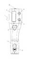
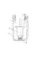
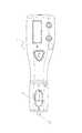
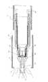
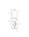
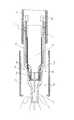
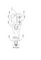
図1及び図2において、1は、本体ケースで、この本体ケース1の先端側には、先端キャップ2が着脱自在に装着されている。Hereinafter, an embodiment of the present invention will be described with reference to the attached drawings.
<1. Configuration>
(1-1. Whole outline of drug injection device)
In FIG. 1 and FIG. 2, 1 is a main body case, and a
また、この本体ケース1の表面には、表示部3、注射ボタン4、質問に対する「はい」を選択する、はいボタン5、質問に対する「いいえ」を選択する、いいえボタン6が設けられている。
また、本体ケース1内には、薬剤シリンジ装着部7と、この薬剤シリンジ装着部7を先端側または、この先端側から後方に移動させる第1の駆動部8と、薬剤を押し出すためのピストン11(図3参照)を先端側に移動させる第2の駆動部9が設けられている。第1の駆動部8は、薬剤シリンジ装着部7とともに第2の駆動部9も先端側或いは後方側へと移動する。Further, on the surface of the
Further, in the
ここで、先端側若しくは前方側とは、先端キャップ2側(注射針が装着される側)のことであり、後端若しくは後方側とは、電源ボタン23が設けられている側のことである。
さらに、薬剤シリンジ装着部7には、薬剤シリンジユニット10が、着脱自在に装着されている。
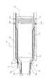
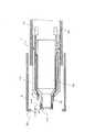
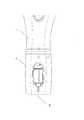
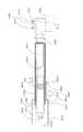
これらの構成について、図3を用いて簡単に説明すると、第1の駆動部8によって、薬剤シリンジ装着部7を構成するインナーケース12を先端側、或いは後方側へと移動させることで、インナーケース12内に装着された薬剤シリンジユニット10も、先端側或いは後方側へと移動する。Here, the distal end side or the front side refers to the
Furthermore, the
These configurations will be briefly described with reference to FIG. 3. The
また、図3に示しているように、薬剤シリンジユニット10には、その先端部に針ユニット13が装着されるので、この針ユニット13も先端側或いは後方側に移動することになる。
この状態、つまり針ユニット13が先端側に移動する状態が、刺針状態で、逆に、針ユニット13が後方側に移動する状態が、抜針状態である。Further, as shown in FIG. 3, since the
In this state, that is, the state in which the
(1−2.薬剤シリンジユニット10)
次に、薬剤シリンジユニット10について、図4〜図8を用いて、説明する。
薬剤シリンジユニット10は、シリンジカバー14と、この内部に装着される薬剤シリンジ15と、この薬剤シリンジ15の先端側に針ユニット13を構成する注射針20(詳細には注射針20が設けられている針基体19、図13参照)が装着されたことを検出する第1検出部材16と、針ユニット13を構成する針ケース17(図13参照)が装着されたことを検出する第2検出部材18とを備えている。(1-2. Drug syringe unit 10)
Next, the
The
薬剤シリンジ15には、図3及び図4に示すようにガスケット34が設けられており、ガスケット34は、第2の駆動部9によって薬剤シリンジユニット10内に挿入するピストン11によって先端側に移動する。このガスケット34の移動によって、薬剤シリンジ15内の薬剤が注射針20から突出する。
第1検出部材16は、図6に示すように、2本の検出レバー16aを有し、この検出レバー16aは図4、図5に示すように、シリンジカバー14の先端側開口部14aを貫通して、先端側に延ばされている。尚、図4は、図5のA´―A間の矢視断面図である。The
The
また、この検出レバー16aは、図6および図8に示すように、後方側において、環状体16bによって、一体化されている。
さらに、図6に示すように検出レバー16aの外周側には突起16cが設けられ、この突起16cは、図4に示すようにシリンジカバー14の内壁に当接する。
また、この突起16cの後方には、突起16dが設けられ、この突起16dは、シリンジカバー14の開口部14bに突入している。Further, as shown in FIGS. 6 and 8, the
Further, as shown in FIG. 6, a
Further, a
つまり、薬剤シリンジユニット10は、この突起16dによって第1検出部材16が先端側へ移動するのを阻止するように構成されている。
次に、第2検出部材18は、図7および図8に示すように2本の検出レバー18aを有し、この検出レバー18aは、図7および図8に示すようにシリンジカバー14の先端側開口部14cを貫通して先端側に延ばされている。That is, the
Next, the
また、この検出レバー18aは、図7に示すように後方側において、環状体18bによって一体化されている。
さらに、環状体18bの先端側の検出レバー18aには、突起18cが設けられ、この突起18cは、シリンジカバー14の開口部14dに突入している。
つまり、薬剤シリンジユニット10は、この突起18cによって第2検出部材18が先端側へ移動するのを阻止するように構成されている。The
Further, a
That is, the
尚、第1検出部材16と第2検出部材18は、薬剤シリンジユニット10を薬剤シリンジ装着部7に装着した状態において、図示しない付勢部によって先端側に付勢されている。
図4に示すシリンジカバー14の先端外周には、ネジ溝14eが設けられ、このネジ溝14eを用いて、図13および図14に示す針ユニット13が着脱される。The
A
(1―3.針ユニット13)
針ユニット13は、図13および図14に示すように、シリンジカバー14のネジ溝14eにねじ込まれる針基体19に植設された注射針20と、注射針20に着脱自在に装着される針キャップ21と、針キャップ21及び針基体19を覆う針ケース17とにより構成されている。(1-3. Needle unit 13)
The
針基体19の外周には、先端から後方に向けて延びた凹凸19aが設けられ、また、針基体19の内周には、シリンジカバー14のネジ溝14eに螺合するネジ溝19bが設けられている。
また、針ケース17の後方側内周には、針基体19の凹凸19aの凹部に係合する突起17aが設けられている。The outer periphery of the
Further, on the inner circumference on the rear side of the
つまり、この突起17aは、先端側から後方側に向かって延びたものであって、針基体19の凹凸19aの凹部にスムーズに差し込むことができる。
そして、突起17aが凹凸19aの凹部に差し込まれた状態であれば、針ケース17の突起17aと針基体19の凹凸19aが係合するため、針ケース17を回転させれば、針基体19も回転する。これにより、針ユニット13が、シリンジカバー14に対して、着脱される。That is, the projection 17 a extends rearward from the tip end side, and can be smoothly inserted into the concave portion of the
Then, if the protrusion 17a is inserted into the recess of the
注射針20の設けられている針基体19が、上記ネジ溝14e(図4参照)に取り付けられると、針基体19の後方側の縁によって第1検出部材16が後方に押される。第1検出部材16の後方への移動を、薬剤シリンジ装着部7に設けられた第1検出スイッチ40(図11参照)によって検出することによって、針基体19が薬剤シリンジユニット10に取り付けられたことが検知される。すなわち、注射針20が薬剤シリンジユニット10に取り付けられたことが検知される。第1検出スイッチ40は、薬剤シリンジユニット10が薬剤シリンジ装着部7に装着された状態において、第1検出部材16の後方側に配置されている。 When the
また、針ケース17が針基体19を介して薬剤シリンジユニット10に取り付けられると、針ケース17の後方側の縁によって第2検出部材18が後方に押される。第2検出部材18の後方への移動を、薬剤シリンジ装着部7に設けられた第2検出スイッチ41(図11参照)によって検出することによって、針ケース17が薬剤シリンジユニット10に取り付けられたことが検知される。第2検出スイッチ41は、薬剤シリンジユニット10が薬剤シリンジ装着部7に装着された状態において、第2検出部材18の後方側に配置されている。 Further, when the
(1−4.制御ブロック)
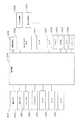
次に、電気的な接続状態について、図25を用いて説明する。
表示部3、注射ボタン4、はいボタン5、いいえボタン6、第1の駆動部8、及び第2の駆動部9は、図25に示すように制御部22に接続されている。
また、この制御部22には、電源ボタン23、センサ24、25、26、27、サウンダ28、メモリ29、バイブレータ30、モータドライブ回路31、過電流検出回路32、充電式電池33、第1検出スイッチ40、および第2検出スイッチ41が接続されている。(1-4. Control block)
Next, the electrical connection state will be described with reference to FIG.
The
In addition, the
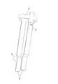
この内、センサ24は、図3に示すように、第1の駆動部8によって、インナーケース12を含む薬剤シリンジ装着部7及び薬剤シリンジユニット10が、図9および図10に示す針交換位置に到達したことを検出するものである。
また、センサ25は、図3に示すように、第1の駆動部8によって、インナーケース12を含む薬剤シリンジ装着部7及び薬剤シリンジユニット10が、図21に示す刺針位置に到達したことを検出するものである。図21は、刺針位置において針ケース17及び針キャップ21が外された状態の薬剤注入装置の先端部分の要部正面図である。Among them, as shown in FIG. 3, in the
Further, as shown in FIG. 3, the
さらに、センサ26は、図3に示すように、第1の駆動部8によって、インナーケース12を含む薬剤シリンジ装着部7及び薬剤シリンジユニット10が、図19及び図20に示す抜針位置(原点位置ともいう)に到達したことを検出するものである。図19は、抜針位置において針ケース17及び針キャップ21が外された状態(注射直前の状態)の薬剤注入装置の先端部分の要部正面図である。 Furthermore, as shown in FIG. 3, the
これらセンサ24、25、26としてはフォトセンサなどを用いることが出来、第2の駆動部9が配置されている筐体に設けられた突起100(図3参照)が光を遮ることによって位置が検出される。
尚、先端側から後方側に向かって、センサ24、25、26の順に配置されているため、先端側から後方側に向かって、針交換位置、刺針位置、抜針位置の順に設けられている。A photo sensor or the like can be used as these
In addition, since the
ここで、刺針位置とは、対象物の一例である人体への薬剤の注入が行われる位置である。より具体的には、図21に示すように、注射針20が、先端キャップ2よりも先端側に位置している状態となる位置である。
また、抜針位置とは、薬剤の注入前に、針ケース17及び針キャップ21を薬剤シリンジユニット10から取り外して注射針20を露出させる位置であり、薬剤の注入後に、針ケース17を注射針20に被せる位置である。より具体的には、図18に示すように、注射針20が先端キャップ2内に配置されており、先端キャップ2から突出していない状態の位置である。Here, the pricking position is a position at which a drug is injected into the human body which is an example of the object. More specifically, as shown in FIG. 21, the
The needle removal position is a position at which the
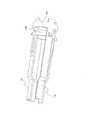
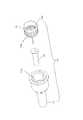
また、針交換位置(針操作位置の一例)とは、針ユニット13の装着又は取り外しが行われる位置であり、抜針位置よりも先端側の位置である。より具体的には、針交換位置とは、例えば、図12に示すように、後述する針ケース17のローレット加工部17cが先端キャップ2よりも先端側に位置している状態となる位置である。また、図11に示すように、先端キャップ2の端面2bからシリンジカバー14の端面14fまでの距離d1が、例えば、約1.6mmと設定される。 Further, the needle replacement position (an example of the needle operation position) is a position where attachment or removal of the
また、センサ27(図3参照)は、ガスケット34(図4参照)の移動量を検出する。すなわち、第2の駆動部9によって、ピストン11が先端側に移動させられ、それによって、薬剤シリンジ15の後端部にあるガスケット34(図4参照)がどの程度移動されたかがセンサ27によって検出される。なお、センサ27の一例には、エンコーダなどがある。 The sensor 27 (see FIG. 3) detects the amount of movement of the gasket 34 (see FIG. 4). That is, the
図15は、薬剤シリンジユニット10に針ユニット13を装着した状態を示す図である。
また、図11および図15に示すように、薬剤シリンジユニット10が薬剤シリンジ装着部7に装着された状態において注射針20が薬剤シリンジユニット10に装着されると、第1検出部材16が後方へと移動し、第1検出スイッチ40がオン状態となるため、制御部22は、注射針20が装着されたことを判断できる。FIG. 15 is a view showing the
Further, as shown in FIGS. 11 and 15, when the
一方、薬剤シリンジユニット10が薬剤シリンジ装着部7に装着された状態において注射針20が薬剤シリンジユニット10から取り外されると、図示しない付勢部材によって第1検出部材16が先端側に移動する。このため、第1検出スイッチ40がオフ状態となり、制御部22は、注射針20が取りはずされたことを判断できる。
薬剤シリンジユニット10が薬剤シリンジ装着部7に装着された状態において針ケース17が薬剤シリンジユニット10に装着されると、第2検出部材18が後方へと移動し、第2検出スイッチ41がオン状態となるため、制御部22は、針ケース17が装着されたことを判断できる。On the other hand, when the
When the
一方、薬剤シリンジユニット10が薬剤シリンジ装着部7に装着された状態において針ケース17が薬剤シリンジユニット10から取り外されると、図示しない付勢部材によって第2検出部材18が先端側に移動する。このため、第2検出スイッチ41がオフ状態となり、制御部22は、針ケース17が取りはずされたことを判断できる。
なお、第1の駆動部8及び第2の駆動部9は、モータドライブ回路31によって駆動され、その時の過電流検出は、過電流検出回路32によって検出される。
また、サウンダ28は、警告などを音声で発し、バイブレータ30は、警告などを振動で発する。
さらに、メモリ29には、図26〜図29に示す注入動作を制御するプログラムなどが格納される。On the other hand, when the
The
In addition, the sounder 28 issues a warning and the like by voice, and the
Furthermore, the
<2.動作>
以上の構成において、本実施形態の薬剤注入装置は、初期状態において図1および図2に示す構成になっている。なお、この図1及び図2は、先端キャップ2が外されて、薬剤シリンジ装着部7に薬剤シリンジユニット10が装着され、その後、先端キャップ2が装着された状態を示している。<2. Operation>
In the above configuration, the drug injection device of the present embodiment is configured as shown in FIG. 1 and FIG. 2 in the initial state. 1 and 2 show a state in which the
つまり、初期状態では薬剤シリンジ装着部7に薬剤シリンジユニット10が装着された状態であり、この時、シリンジカバー14の先端にあるネジ溝14eも先端キャップ2内に留まった状態である(図2参照)。
次に、注射をするために、電源ボタン23をオンすると(図26のS1)、制御部22は、表示部3に、図30(a)に示すように注射するか否かのメッセージを表示する(図26のS2)。That is, in the initial state, the
Next, when the
この状態で、はいボタン5を押下すると、図4から図8に示した第1検出部材16および第1検出スイッチ40によって注射針20(詳細には針基体19)の装着状態が検出される(図26のS3,S4,S5)。
ここで、薬剤シリンジユニット10に、注射針20が装着されていないと、第1の駆動部8によって、図9〜図11に示すように、インナーケース12を含む薬剤シリンジ装着部7および薬剤シリンジユニット10が、針交換位置に移動させられる(図26のS6)。In this state, when the
Here, if the
この時、第1の駆動部8によってインナーケース12を含む薬剤シリンジ装着部7及び薬剤シリンジユニット10が図9に示す針交換位置に到達することは、センサ24によって検出される。
すると、制御部22は、図30(b)に示すように表示部3に注射針20の装着を促す表示を行なう(図26のS7)。At this time, the
Then, the
それを受けて、使用者は、図13及び図14に示すように、一体となった針ユニット13の針ケース17を摘んで、その内部に存在する針基体19の内周に設けたネジ溝19bを、図9及び図10に示す薬剤シリンジユニット10の先端部にあるネジ溝14eに螺合させる。
このとき、図12、図13、及び図15に示すように、針ケース17の後方には、径大部17bが設けられ、此処に滑り止めのためのローレット加工部17cが設けられている。そのため、針ケース17を回転させやすく、その結果として、針ユニット13を薬剤シリンジユニット10の先端側に容易に取り付けることができる。In response to this, as shown in FIG. 13 and FIG. 14, the user pinches the
At this time, as shown in FIG. 12, FIG. 13 and FIG. 15, a
なお、この状態においては、図12、図13、及び図15に示すように、注射針20は、先端キャップ2の先端開口部2aから先端側に突出した状態となっているが、その外周は、針キャップ21および針ケース17によって覆われているので、不用意な穿刺を防止出来る。
そして、このように、薬剤シリンジユニット10の先端に針ユニット13が装着されると、注射針20の装着を第1検出部材16および第1検出スイッチ40が検出し(図26のS8)、また、針ケース17の有無は、第2検出部材18および第2検出スイッチ41によって検出される(図26のS9)。In this state, as shown in FIG. 12, FIG. 13 and FIG. 15, the
Then, as described above, when the
すると、制御部22は、表示部3に、図30(e)に示すように、注射針20の取り付けが完了したかを問う表示をさせる(図27のS21)。
すると、使用者は、はいボタン5を押下し、その結果、第1の駆動部8によって、図16〜図18に示すように、インナーケース12を含む薬剤シリンジ装着部7及び薬剤シリンジユニット10が、抜針位置に移動させられる(図27のS22、S23、S24)。Then, the
Then, the user presses the
次に制御部22は、表示部3に、図30(g)に示すように、針ケース17と針キャップ21を取り外すような表示を行なう(図27のS25)。この抜針位置は、上述したようにセンサ26によって検知される位置であり、針原点位置ともいう。
この抜針位置の状態では、図16〜図18に示すように、注射針20は、先端キャップ2の先端開口部2aよりも後方に位置した状態となっている。このため、抜針位置において、図17に示すように、針ユニット13の針ケース17を先端側に引き抜き、続いて、図18に示すように、針キャップ21を引き抜いても、注射針20は先端キャップ2内に存在している。そのため、不用意な穿刺が防止できる。Next, as shown in FIG. 30G, the
In the state of the needle removal position, as shown in FIG. 16 to FIG. 18, the
なお、針ケース17の突起17aと、針基体19に設けた凹凸19aの凹部とは、ともに先端側から後方側に延びて形成されているので、針ケース17を針基体19から引き抜くことは、容易に行なうことが出来る。
また、針キャップ21は、注射針20に軽い係合状態で被せただけのものであるので、これも容易に引き抜くことができる。The protrusion 17 a of the
In addition, since the
そして、針ケース17が取り外された状態では、図18に示すように、第2検出部材18が前方に移動するため第2検出スイッチ41がオフ状態となり、制御部22は、針ケース17が取り外されたことを検出する(図27のS26)。
すると、制御部22は、表示部3に、図30(h)に示すように注射ボタンを押して下さいとの表示を行わせる(図28のS31)。Then, when the
Then, the
使用者が、先端キャップ2を皮膚の注射位置に当て、その状態で、注射ボタン4を押すと(図28のS32)、第1の駆動部8によってインナーケース12を含む薬剤シリンジ装着部7及び薬剤シリンジユニット10が先端側に移動する。この移動によって、図21および図22に示すように、注射針20が先端キャップ2から突出する。これにより皮膚に刺針が行なわれる(図28のS33)。その後、表示部3に、図30(f)に示すように、注射中である旨の表示が行われる(図28のS34)。 When the user places the
引き続き、制御部22が、第2の駆動部9によりピストン11を先端側に移動させることにより、薬剤シリンジ15内の薬剤が注射針20を通して体内に所定量を注入される(図28のS35)。
なお、上記のように予め設定された所定量を注入すると、ピストン11は、通常その位置に留まる。そして、次回の注入時に、その位置から開始するが、薬剤シリンジ15内の薬剤を使い切った場合などは、薬剤シリンジ15の交換のためにピストン11は第2の駆動部9によって初期位置(ピストン11の原点位置)まで後方に移動させられる。Subsequently, the
In addition, if the predetermined amount preset as mentioned above is inject | poured,
ただし、初期位置(ピストン11の原点位置)までの移動は、針原点位置まで移動した後に行なわれる。
注入動作終了後、制御部22は、第1の駆動部8によって薬剤シリンジ装着部7ごと注射針20を図19に示す抜針位置まで後方に移動させ(図28のS36)、図30(j)に示す注入動作終了を表示部3に表示させる(図28のS37)。However, the movement to the initial position (the origin position of the piston 11) is performed after the movement to the needle origin position.
After the injection operation is completed, the
その後、図30(d)に示すように、制御部22は針ケース17を装着することを促す表示を表示部3に行わせる(図29のS41)。
そこで、使用者は、図23に示すように、注射針20の外周を覆うように針ケース17を先端キャップ2の先端開口部2aから挿入して針基体19に装着する。これにより針ケース17の装着が完了する。Thereafter, as shown in FIG. 30D, the
Therefore, as shown in FIG. 23, the user inserts the
すると、第2検出部材18および第2検出スイッチ41が、この針ケース17の装着を検出し(図29のS42)、その結果、制御部22は、図24に示すように第1の駆動部8によって薬剤シリンジ装着部7ごと注射針20を針交換位置まで先端側に移動させる(図29のS43)。続いて、制御部22は、図30(k)に示すように、注射針20を取り外すことを促す表示を表示部3に行なわせる(図29のS44)。ここで、この針交換位置は、上述の注射針20を皮膚に刺針する刺針位置よりも先端側に設けられた位置である。 Then, the
そこで、使用者は、図24において、針ケース17に設けた滑り止めのためのローレット加工部17cを摘んで針ケース17を回転させる。これにより、針ケース17で覆った状態で注射針20を簡単に取り外すことができる。
つまり、注射針20を取り外す時には、注射針20が針ケース17で覆われた状態で、且つ針ケース17のローレット加工部17cが先端キャップ2の先端開口部2aよりも外部に露出した状態であるので、注射針20の取外しが簡単に且つ安全に行うことが出来る。Therefore, in FIG. 24, the user rotates the
That is, when removing the
すると、薬剤シリンジユニット10から針ユニット13(ここでは、針キャップ21は含まれていない)が取り外されたことが第1検出部材16および第1検出スイッチ40により検出されるので(図29のS45)、制御部22は、第1の駆動部8によって、図1に示すように抜針位置までインナーケース12を含む薬剤シリンジ装着部7及び薬剤シリンジユニット10を後方に移動させる(図29のS46)。 Then, it is detected by the
そして、この状態になると、制御部22は、図30(i)に示すように電源をオフにする旨を表示部3に表示させ(図29のS47)、電源をオフする(図29のS48)。
以上の説明が、一連の正常動作であるが、図26、図27、及び図29に示した他の動作についても、以下に説明する。
まず、図26のS10について説明する。注射をするために電源ボタン23がオンされると(図26のS1)、制御部22は、図30(a)に示すように表示部3に注射するか否かのメッセージを表示(図26のS2)させる。この状態で、いいえボタン6が押下された場合に、制御がS10に進み、電源がオフの状態となって終了する。Then, in this state, the
The above description is a series of normal operations, but other operations shown in FIG. 26, FIG. 27, and FIG. 29 will also be described below.
First, S10 of FIG. 26 will be described. When the
次に、図26のS11について説明する。注射をするために、電源ボタン23がオンされると(図26のS1)、制御部22は、図30(a)に示すように表示部3に注射するか否かのメッセージを表示させる(図26のS2)。次に、はいボタン5が押下げられたが、S5において第1検出部材16および第1検出スイッチ40によって注射針20が装着している状態が検出された場合に、制御がS11へと進み、S11に示す表示が行われる。つまり、図30(c)に示すように、針交換を促す内容が表示部3に表示される。 Next, S11 of FIG. 26 will be described. When the
ここで、いいえボタン6を押下すると(図26のS12)、制御が図29のS49へと移行する。この図29のS49で、針ケース17の装着の有無が第2検出部材18および第2検出スイッチ41によって検出される。つまり、針ケース17が検出できない時には、制御は図29のS41へと進み、針ケース17を検出した時には、制御は図29のS43へと移行するのである。このように、電源ボタン23をオンしたときに既に注射針20が装着されている状態であって新しい注射針に交換していない場合には、注射を行わずに注射針20を取り外して電源をオフするように制御が進む。 Here, when the no
再び、図26に戻って、S11の状態で、はいボタン5が押下されると(図26のS13)、図27のS27へと制御が移行する。
このように針ケース17の有無が検出され、針ケース17が装着されているときには図27のS25へと制御が移行し、また、針ケース17が検出されない時には、図28のS31へと制御が移行する。すなわち、注射針20の交換が予め行われているため、針ケース17が装着されている場合には針ケース17を取り外し、針ケース17が装着されていない場合には、その状態で薬剤の注入動作が行われる。
再び、図26に戻って説明すると、図26のS9において、針ケース17が検出されない時には、制御部22は、図30(d)に示すように表示部3に針ケース装着を促す表示を行なわせる(図26のS14)。Returning again to FIG. 26, when the
As described above, the presence or absence of the
Referring back to FIG. 26 again, when the
(主な特徴)
本実施の形態の薬剤注入装置は、本体ケース1と、先端キャップ2と、第1の駆動部8と、第2の駆動部9と、制御部22とを備えている。本体ケース1は、先端側に薬剤シリンジ装着部7を有する。先端キャップ2は、本体ケース1の先端側に着脱自在に装着される。第1の駆動部8は、薬剤シリンジ装着部7に装着される薬剤シリンジユニット10を先端側或いは後方側へと移動させる。第2の駆動部9は、薬剤シリンジユニット10を構成する薬剤シリンジ15のガスケット34を先端側に移動させる。制御部22は、第1の駆動部8及び第2の駆動部9に接続され、薬剤シリンジユニット10への注射針20の装着時、または薬剤シリンジユニット10からの注射針20の取り外し時には、薬剤シリンジ装着部7を、第1の駆動部8によって、抜針位置よりも先端側の針交換位置(針操作位置の一例)に移動させる。(Major features)
The drug injection device of the present embodiment includes a
以上のように、本実施形態においては、制御部22により、薬剤シリンジユニット10への注射針20の装着時、または薬剤シリンジユニット10からの注射針20の取り外し時には、薬剤シリンジ装着部7を、第1の駆動部8によって抜針位置よりも先端側に移動させる構成としている。そのため、薬剤シリンジユニット10への注射針20の装着時、または薬剤シリンジユニット10からの注射針20の取り外し時、本体ケース1から先端キャップ2を取り外さなくても、注射針20の装着または取り外し作業を実行することができ、極めて使い勝手の良いものとなる。 As described above, in the present embodiment, when attaching the
(他の実施形態)
(A)
上記実施形態では、針交換位置において、注射針20の交換が行われているが、針交換位置が設けられず、刺針位置で針交換が行なわれても良い。更には、刺針位置に限らず、抜針位置と刺針位置の間で針交換が行なわれても良い。要するに、抜針位置よりも先端方向側の位置において針ユニット13の交換が行なわれれば良いが、少なくともローレット加工部17cの一部が先端キャップ2の先端開口部2aから外部に出ている方が針ユニット13の交換をより行いやすいため好ましい。(Other embodiments)
(A)
In the above embodiment, replacement of the
(B)
また、上記実施形態では、針ユニット13には針キャップ21が設けられていたが、針キャップ21が設けられておらず、針ケース17が直接注射針20を覆うような構成であってもよい。
(実施の形態2)
以下、本発明の実施の形態2を、添付図面を用いて説明する。
<1.構成>
(1−1.薬剤注入装置の全体概要)
図31〜図33において、1001は、本体ケースで、この本体ケース1001の先端側には、先端キャップ1002が着脱自在に装着されている。(B)
Moreover, in the said embodiment, although the
Second Embodiment
Hereinafter,
<1. Configuration>
(1-1. Whole outline of drug injection device)
In FIGS. 31 to 33,
また、この本体ケース1001の表面には、表示部1003、注射ボタン1004、質問に対する「はい」を選択する、はいボタン1005、質問に対する「いいえ」を選択する、いいえボタン1006が設けられている。
また、本体ケース1001内には、図33及び図34に示す薬剤シリンジ装着部1007と、この薬剤シリンジ装着部1007を先端側または、この先端側から後方に移動させる第1の駆動部1008と、薬剤を押し出すためのピストンユニット1011を先端側に移動させる第2の駆動部1009が設けられている。第1の駆動部1008は、薬剤シリンジ装着部1007とともに第2の駆動部1009も先端側或いは後方側へと移動する。尚、第1の駆動部1008及び第2の駆動部1009としては、例えばステッピングモータ等を用いることが出来る。Further, on the surface of the
In the
ここで、先端側若しくは前方側とは、先端キャップ1002側(注射針が装着される側)のことであり、ピストン1015の薬剤シリンジ1040への挿入方向側ともいえる。又、後端若しくは後方側とは、第2の駆動部1009や電源ボタン1017が設けられている側のことであり、薬剤シリンジ1040からピストン1015を引き出す方向側ともいえる。 Here, the distal end side or the front side refers to the
さらに、薬剤シリンジ装着部1007には、薬剤シリンジユニット1010が、着脱自在に装着されている。
これらの構成について、図34を用いて説明する。
薬剤シリンジ装着部1007は、インナーケース1012を有しており、インナーケース1012内に薬剤シリンジユニット1010が装着される。インナーケース1012内であって、装着される薬剤シリンジユニット1010の後側には、第2の駆動部1009によって駆動されるピストンユニット1011が配置されている。このピストンユニット1011は、薬剤シリンジユニット1010内に挿入されるピストン1015を有している。又、薬剤シリンジユニット1010は、シリンジケース1042と、シリンジケース1042に収納された薬剤シリンジ1040とを有している。この薬剤シリンジ1040内には、ガスケット1041が設けられている。Furthermore, a
These configurations will be described with reference to FIG.
The drug
上記第1の駆動部1008によって、薬剤シリンジ装着部1007を構成するインナーケース1012を先端側或いは後方側へと移動させることで、インナーケース1012内に装着された薬剤シリンジユニット1010も先端側或いは後方側へと移動する。
また、図34に示しているように、この薬剤シリンジユニット1010には、その先端部に針ユニット1013が装着されるので、この針ユニット1013も先端側或いは後方側に移動することになる。The
Further, as shown in FIG. 34, since the
この状態、つまり針ユニット1013が先端側に移動する状態が、刺針状態であり、逆に、針ユニット1013が後方側に移動する状態が、針原点(抜針)状態である。
なお、針ユニット1013は注射針1014を有し、刺針時には、注射針1014は、先端キャップ1002の先端の開口部1002sから先端側に突出し、皮膚に刺針させる。In this state, that is, the state in which the
The
また、この刺針時には、先端キャップ1002の先端側に皮膚が押し当てられ、この状態で、第1の駆動部1008によって注射針1014がインナーケース1012ごと先端キャップ1002側に移動させられる。これにより、注射針1014の皮膚への刺針が実行される。
さらに、この刺針後には、第2の駆動部1009によってピストンユニット1011が駆動し、このピストンユニット1011を構成するピストン1015が薬剤シリンジユニット1010内に移動する。これにより、薬剤シリンジユニット1010を構成する薬剤シリンジ1040のガスケット1041が先端側に移動するため、薬剤シリンジ1040内の薬剤が、注射針1014を介して人体内に注入される。Further, at the time of this piercing, the skin is pressed to the tip side of the
Furthermore, after this needle insertion, the
(1−2.制御ブロック)
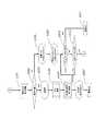
次に、電気的な接続状態について、図35を用いて説明する。
表示部1003、注射ボタン1004、はいボタン1005、いいえボタン1006、第1の駆動部1008、及び第2の駆動部1009は、図35に示すように、制御部1016に接続されている。(1-2. Control block)
Next, the electrical connection state will be described with reference to FIG.
The
また、この制御部1016には、電源ボタン1017、センサ1018、1019、1020、1021、サウンダ1022、メモリ1023、バイブレータ1024、モータドライブ回路1025、充電式電池1026、タイマ1027が接続されている。
なお、センサ1018は、図34に示すようにインナーケース1012を含む薬剤シリンジ装着部1007及び薬剤シリンジユニット1010が最後端まで下がった状態を検出する。このセンサ1018が検出した状態とは、図31の状態であり、この時は、注射針1014が先端キャップ1002内に後退した状態である。Further, a
The
また、センサ1019は、図34に示すようにインナーケース1012を含む薬剤シリンジ装着部1007及び薬剤シリンジユニット1010が最先端まで進んだ状態を検出する。このセンサ1019が検出した状態とは、図32の状態であり、この時は、注射針1014が先端キャップ1002から先端側に突出し、皮膚に刺針された状態である。
これらセンサ1018、1019としてはフォトセンサなどを用いることが出来、それぞれ投光部及び受光部を有し、第2の駆動部1009が配置されている筐体に設けられた突起1100が光を遮ることによって位置が検出される。Further, as shown in FIG. 34, the
A photo sensor etc. can be used as these
さらに、センサ1020は、本体ケース1001に対して先端キャップ1002が装着されたか否かを検出するもので、このセンサ1020は、図33に示すように先端キャップ1002が本体ケース1001から外された状態と、図32に示すように先端キャップ1002が本体ケース1001に装着された状態の双方を検出出来る。
また、センサ1021は、第2の駆動部1009の駆動量を検出する。具体的には、センサ1021は、第2の駆動部1009を構成するモータの回転数を検出するエンコーダのことであり、ピストン1015が薬剤シリンジユニット1010に対して、どの程度押し込まれているかを検出できる。Further, the
The
(1−3.装着状態検出部1030)
上記センサ1020を用いて、本体ケース1001への先端キャップ1002の装着状態を検知する装着状態検出部1030について説明する。
装着状態検出部1030は、検出レバー1031と、上記センサ1020と、付勢部材(図示せず)を有している。検出レバー1031は、インナーケース1012の移動方向と平行な方向に移動可能に本体ケース1001に支持されており、インナーケース1012と並んで配置されている。また、検出レバー1031は図示しない付勢部材によって先端側に向かって(図34において、向かって左方向へ)付勢されている(図34参照)。また、センサ1020はフォトセンサであって、投光部と受光部を有し、投光部からの光を受光部が検出する。この投光部と受光部の間に遮蔽物が挿入されると、光が遮断されて受光部が光を検知できなくなり、遮蔽物の存在が検知される。(1-3. Wearing state detection unit 1030)
The mounting
The mounting
先端キャップ1002を本体ケース1001に装着すると、先端キャップ1002の後端部1002aによって検出レバー1031は付勢力に逆らって(つまり、先端側とは反対方向;図34において、向かって右方向に)押される。すると、検出レバー1031の後端部1031aがセンサ1020内の光を遮断し、先端キャップ1002の装着が検出される。 When the
つまり、検出レバー1031の後端部1031aが、センサ1020の上記投光部と受光部の間に入ることにより、フォトセンサの出力が変化する。そのフォトセンサの出力の変化を制御部1016が検出することにより、先端キャップ1002が装着されたことが分かる。
一方、先端キャップ1002を本体ケース1001から取り外すと、図示しない付勢部材によって検出レバー1031が先端側へ(図34において、向かって左方向へ)と移動し、検出レバー1031がセンサ1020内の光を遮断しなくなるため、先端キャップ1002の未装着が検出される。That is, when the
On the other hand, when the
<2.動作>
次に、本実施の形態の薬剤注入装置の動作について説明する。
図37〜図40は、本実施の形態の薬剤注入装置の動作を説明するフロー図である。図36は、図37〜図40に示す動作の際の表示の例を示す図である。
(2−1.通常薬剤注入モード)
はじめに、通常の薬剤注入が実行される通常薬剤注入モードについて説明する。<2. Operation>
Next, the operation of the pharmaceutical injection device of the present embodiment will be described.
37 to 40 are flowcharts illustrating the operation of the pharmaceutical injection device according to the present embodiment. FIG. 36 is a diagram showing an example of display in the operation shown in FIG. 37 to FIG.
(2-1. Normal drug injection mode)
First, a normal drug injection mode in which a normal drug injection is performed will be described.
まず、図31に示す状態から、薬剤注入を行なうときには、使用者によって電源ボタン1017が押される(図37のS101)。
すると、制御部1016は、センサ1018によって、インナーケース1012を含む薬剤シリンジ装着部1007、薬剤シリンジユニット1010及び注射針1014が原点位置に戻っているか否かを検出し、原点位置に配置されていれば、次に、表示部1003に、図36(a)のように、「注射しますか?」と表示させる(図37のS102、S103)。First, when performing medicine injection from the state shown in FIG. 31, the user presses the power button 1017 (S101 in FIG. 37).
Then, the
使用者は、この表示を確認し、次に、はいボタン1005を操作することになる(図37のS104)。
すると、制御部1016は、センサ1020によって、図31に示すように本体ケース1001に先端キャップ1002が装着されているか否かを検出する(図38のS201)。The user confirms this display, and then operates the Yes button 1005 (S104 in FIG. 37).
Then, the
図31の状態では、本体ケース1001に先端キャップ1002が装着されているので、制御部1016は、表示部1003に図36(c)に示すように、「注射ボタンを押してください」と表示させる(図38のS202)。
使用者は、この表示を見て、注射ボタン1004を操作することになる(図38のS203)。In the state of FIG. 31, since the
The user sees this display and operates the injection button 1004 (S203 in FIG. 38).
すると、第1の駆動部1008により、インナーケース1012を含む薬剤シリンジ装着部1007と注射針1014が、図32に示すように、先端側に移動し、その結果として、注射針1014は先端キャップ1002から先端側に突出され、皮膚に刺針される(図39のS301)。
この状態は、センサ1019によって検出され(図39のS302)、表示部1003には、図36(e)に示すように「注射中」との表示が行われる(図39のS303)。Then, the first
This state is detected by the sensor 1019 (S302 in FIG. 39), and “in injection” is displayed on the
また、この状態になると、第2の駆動部1009によって、ピストン1015が薬剤シリンジユニット1010を構成する薬剤シリンジ1040内を先端側に移動させられる。これによって、薬剤シリンジ1040内の薬剤が、注射針1014を経由して人体に注入される(図39のS304)。
その後、制御部1016は、第1の駆動部1008を反転駆動する。それによって、インナーケース1012を含む薬剤シリンジ装着部1007と薬剤シリンジユニット1010と注射針1014が、図31の状態(原点位置)まで戻される。尚、原点位置まで戻ったことは、センサ1018によって検出される。
続いて、制御部1016は、図36(f)に示すように表示部1003に「注射が終わりました」と表示させ、その後、電源をオフ状態とする(図39のS305、S306、S307)。
以上が、通常の薬剤注入動作であるが、以下、さまざまな状態について説明する。Also, in this state, the
Thereafter, the
Subsequently, as shown in FIG. 36F, the
The above is the normal medicine injection operation, but various states will be described below.
(2−2.第1の駆動部1008の不具合検出及び簡易薬剤注入モードへの移行)
次に、第1の駆動部1008に故障が検出された場合における簡易薬剤注入モードへの制御フローの移行の動作について説明する。(2-2. Detection of malfunction of
Next, the operation of transition of the control flow to the simple medicine injection mode when a failure is detected in the
まず、図37のS102において、インナーケース1012を含む薬剤シリンジ装着部1007、薬剤シリンジユニット1010及び注射針1014が、図31の状態に無い時(原点位置ではないとき)には、制御部1016は、第1の駆動部1008によって、これらを図31の原点位置まで戻す(図37のS105)。
そして、センサ1018によって原点位置に到達したことが確認されると、制御は図37のS103へと移行する(図37のS106)。First, in S102 of FIG. 37, when the drug
Then, when it is confirmed by the
一方、このS106において、原点位置に戻ったことが検出できない場合には、制御部1016は、表示部1003に、図36(b)に示すように「簡易注入モードで注射しますか?」と表示をさせる(図37のS107)。
このような状態では、第1の駆動部1008が故障したりすることで、インナーケース1012を含む薬剤シリンジ装着部1007、薬剤シリンジ装着部1007に装着されている薬剤シリンジユニット1010及び注射針1014を前方に押し出すことが出来ないと考えられる。つまり、原点位置に戻ったことが検出できない場合には、注射針1014を先端キャップ1002から先端側に突出させること(図32参照)が出来ない状態になっていると考えられる。On the other hand, when it is not detected in this S106 that the return to the origin position is detected, the
In such a state, when the
使用者は、図37のS107の表示を確認後、薬剤注入を行なう場合には、はいボタン1005を操作し、薬剤注入を行なわない場合には、いいえボタン1006を操作する(図37のS108、S109)。
ここで、はいボタン1005を操作した場合は、図40のS401に移り、制御は、簡易注入モードに移行する。
また、使用者がいいえボタン1006を操作した場合には、薬剤注入装置の電源をオフして、動作が終了する(図37のS110)。The user operates the
Here, when the
When the user operates the No
(2−3.簡易薬剤注入モード)
次に、簡易薬剤注入モードの動作について、図40を参照して説明する。この簡易注入モードとは、注射針1014を第1の駆動部1008によって刺針できない状態であっても、薬剤を注入しようとする動作である。(2-3. Simple drug injection mode)
Next, the operation of the simple medicine injection mode will be described with reference to FIG. The simple injection mode is an operation to inject a medicine even in a state in which the
この場合は、まず、先端キャップ1002が本体ケース1001から、図33のように、取り外されているか否かが、センサ1020により検出される(図40のS401)。
このとき、先端キャップ1002が装着されたままの状態になっていることが、センサ1020で検出された場合には、制御部1016は、図36(i)に示すように、表示部1003に「先端キャップを取り外して下さい」との表示をさせ、使用者により、先端キャップ1002を取り外すように促す(図40のS402)。In this case, first, whether or not the
At this time, when it is detected by the
そして、図31の状態から図33のように、先端キャップ1002が本体ケース1001から取り外されたことが、センサ1020によって検出されると、制御部1016は、表示部1003に、図36(k)に示すように、「空気抜きをします」と表示させる(図40のS403)。
つまり、第1の駆動部1008が故障している状態で、第2の駆動部1009が安定動作できる状態にあるか否かを確認するために、この空気抜き動作が実行される。When the
That is, in the state where the
従って、使用者は、はいボタン1005を操作し、それによって、空気抜き動作が実行される(図40のS404、S405)。
この空気抜き動作とは、第2の駆動部1009によって、ピストン1015を先端側に、わずかに押し出し、それによって、薬剤シリンジ内の薬剤を注射針1014から突出させる。この薬剤の突出を使用者に確認させることで、空気抜き動作の実施確認が行われる。Therefore, the user operates the
In this air release operation, the
つづいて、制御部1016は、表示部1003に、図36(l)に示すように「正常に空気抜きが出来ましたか?」と表示をさせる(図40のS406)。
使用者は、先ほど、注射針1014から薬剤が突出されたことを確認しているので、はいボタン1005を操作することになる(図40のS407)。
また、注射針1014から薬剤が突出されたことが確認できない場合には、いいえボタン1006が操作されることになるが、この時には、制御は、図40のS403へと戻る(図40のS408)。Subsequently, the
Since the user has previously confirmed that the medicine has been ejected from the
Further, if it is not confirmed that the medicine has been ejected from the
さて、図40のS406で、はいボタン1005が操作されると、制御部1016は、表示部1003に図36(h)に示すように「注射針を刺した後に、注射ボタンを押してください」と表示させる(図40のS409)。
この表示を見た使用者は、図33のように、注射針1014が露出した状態で、その注射針1014を皮膚に刺針し、その後、注射ボタン1004を操作する(図40のS410)。Now, when the
The user who sees this display pierces the
すると、制御部1016は、表示部1003に、図36(e)に示すように「注射中」と表示させ、薬剤注入動作を実行させる(図40のS411、S412)。
薬剤注入動作とは、第2の駆動部1009によってピストン1015が薬剤シリンジユニット1010を構成する薬剤シリンジ1040内を先端側に移動させられ、これによって、薬剤シリンジ1040内の薬剤が注射針1014を経由して人体に注入される動作である。
そして、この注入動作が終了すると、制御部1016は、図36(f)に示すように「注射が終わりました」と表示部1003に表示させ、次に、電源をオフの状態とする(図40のS413、S414)。Then, the
In the drug injection operation, the
Then, when the injection operation is completed, the
(2−4.薬剤注入の補助構成のトラブル認識済み状態における簡易薬剤注入モードへの移行)
インナーケース1012を含む薬剤シリンジ装着部1007、薬剤シリンジユニット1010及び注射針1014が原点位置には戻っているものの、薬剤注入の補助構成(第1の駆動部1008の故障及び先端キャップ1002の紛失又は破損)のトラブルが使用者によって予め認識されている状態における制御フローの簡易薬剤注入モードへの移行について説明する。(2-4. Transition to the simplified drug injection mode in the trouble-recognized state of the auxiliary configuration for drug injection)
Although the drug
図37のS103の状態で、いいえボタン1006を操作した場合(図37のS111)について、図41を参照して説明する。
まず、制御部1016は、表示部1003に、図36(j)に示すように「終了しますか?」と表示させる(図41のS501)。
使用者は、この表示を確認し、薬剤注入をやめる場合は、はいボタン1005を操作し、簡易薬剤注入モードを実行する場合には、いいえボタン1006を操作する(図41のS502、S503)。The case where the no
First, the
The user confirms this display, and operates the
ここで、はいボタン1005を操作した場合には、制御部1016は電源をオフ状態にし、制御が終了する(図41のS504)。
また、ここで、いいえボタン1006を操作した場合には、制御部1016は、表示部1003に、図36(b)に示すように「簡易注入モードで注射しますか?」と表示する(図41のS505)。Here, when the
Further, when the no
これに対して、使用者は、簡易注入動作もしない場合には、いいえボタン1006を操作する。この操作により、制御部1016は、電源オフにし、制御は終了される(図41のS506、S507)。
このとき、簡易注入動作を行う場合は、はいボタン1005を操作し、図40のS401に移り、簡易注入モードへ移行する(図41のS508)。On the other hand, the user operates the No
At this time, in the case of performing the simple injection operation, the
この動作は、第1の駆動部1008が故障して、針原点位置には戻っているものの、インナーケース1012を含む薬剤シリンジ装着部1007、薬剤シリンジユニット1010及び注射針1014を先端側に移動させることが出来ない場合においても、第2の駆動部1009のみを駆動させて、簡易注入を行う動作である。また、この動作は、先端キャップ1002の紛失または破損を予め認識している場合に、第2の駆動部1009のみを駆動させて、簡易注入を行う動作である。 In this operation, although the
(2−5.先端キャップ1002未装着状態における簡易薬剤注入モードへの移行)
次に、先端キャップ1002を紛失した場合、先端キャップ1002が破損した場合などによって、通常薬剤注入モードが実行できない状態における簡易薬剤注入モードへの制御の移行について説明する。
図38のS201において、先端キャップ1002が本体ケース1001に装着されていないことが、センサ1020によって検出された場合には、制御部1016は、表示部1003に図36(d)に示すように「先端キャップを取り付けてください」と表示させ、使用者に先端キャップ1002の装着を促す(図38のS204)。(2-5. Transition to the simple drug injection mode in the state where the
Next, the transition of control to the simplified drug injection mode in a state in which the normal drug injection mode can not be performed depending on the case where the
If it is detected by the
制御部1016は、タイマ1027を使用して、所定時間、先端キャップ1002が装着されるのを監視する(図38のS205)。
つまり、所定時間(図38のS205に示す例では、10分)経過するまで、図38のS201、S204、S205を繰り返すことになる。
その間に、先端キャップ1002が本体ケース1001に装着された場合には、制御部1016は、表示部1003に図36(c)に示すように「注射ボタンを押してください」と表示させ、通常薬剤注入モードの動作を実行するようになる。The
That is, S201, S204, and S205 of FIG. 38 are repeated until a predetermined time (10 minutes in the example shown in S205 of FIG. 38) elapses.
In the meantime, when the
一方、上記の所定時間内に、先端キャップ1002が本体ケース1001に装着されたことを検出できなかった場合には、制御部1016は、表示部1003に図36(b)に示すように「簡易注入モードで注射しますか?」と表示させる(図38のS206)。
使用者は、この表示を確認後、簡易注入動作をしない場合には、いいえボタン1006を操作し、先端キャップ1002の装着確認へ移行する(図38のS207)。On the other hand, if it is not possible to detect that the
If the user does not perform the simple injection operation after confirming the display, the user operates the No
また、使用者が、簡易注入動作をする場合は、はいボタン1005を操作し、図40のS401に移り、制御は簡易注入モードに移行する(図38のS208)。
この動作は、先端キャップ1002が壊れていたり、先端キャップ1002を無くしていたりした場合においても、簡易薬剤注入モードを実行する動作である。
通常注入動作においては、第1の駆動部1008を駆動するには、先端キャップ1002の本体ケース1001への装着が条件となっている。そのため、先端キャップ1002が壊れたり、無くしたりした場合には、本体ケース1001に先端キャップ1002を装着できないので、センサ1020による先端キャップ1002の本体ケース1001への装着検出が不可能であり、第1の駆動部1008は起動できない。When the user performs the simple injection operation, the user operates the
This operation is an operation to execute the simple medicine injection mode even when the
In the normal injection operation, in order to drive the
このように先端キャップ1002の装着が通常注入動作における第1の駆動部1008の起動条件とされている。これは、通常注入動作では、第1の駆動部1008によってインナーケース1012と注射針1014を先端側に移動させて皮膚への刺針をしようとするが、先端キャップ1002が無い場合には、薬剤注入装置の先端を皮膚に適切に当接できないので、適切な刺針ができないためである。 As described above, the attachment of the
このように、通常注入動作では、先端キャップ1002が装着されていない場合には薬剤の注入を行うことができないが、簡易薬剤注入モードでは(2−3)で述べたように第1の駆動部1008を動作させずに薬剤注入を行うことが出来る。
すなわち、簡易薬剤注入モードでは、薬剤注入装置によって刺針動作が行われないため、使用者が刺針を行った後に、薬剤注入装置によって薬剤の注入が行われる。As described above, in the normal injection operation, the drug can not be injected when the
That is, in the simple medicine injection mode, since the needle injection operation is not performed by the medicine injection device, the medicine injection is performed by the medicine injection device after the user performs the needle insertion.
(2−6.第1の駆動部1008の不具合検出及び簡易薬剤注入モードへの移行)
次に、第1の駆動部1008に故障が検出された場合における簡易薬剤注入モードへの制御フローの移行について説明する。尚、(2−2)では、注射針1014等が原点位置に配置されていないことによって第1の駆動部1008の不具合を検出したが、この(2−6)では、原点位置から刺針位置に移動できないことによって第1の駆動部1008の不具合の検出が行われる。(2-6. Detection of malfunction of
Next, transition of the control flow to the simple medicine injection mode when a failure is detected in the
図39のS301において、第1の駆動部1008によって、刺針位置まで移動させるが、この時、刺針位置まで移動したことが、センサ1019において検出できなかった場合(図39のS302)、制御部1016は、表示部1003に図36(g)に示すように「針刺しができませんでした」と表示し、刺針動作の不具合を通知する(図39のS308)。 In S301 of FIG. 39, the
これは、通常の薬剤注入動作時において、第1の駆動部1008の故障が発生したか、または、それ以外の原因で刺針動作が出来なかったことを示している。
制御部1016は、図36(g)の表示を一定時間表示後、表示部1003に、図36(b)に示すように「簡易注入モードで注射しますか?」と表示する(図39のS309)。This indicates that the failure of the
After the
この表示に対して、使用者は、簡易注入動作をしない場合には、いいえボタン1006を操作し、この操作により、制御部1016は、電源をオフして制御を終了する(図39のS310、S311)。
一方、簡易注入動作を行う場合には、はいボタン1005を操作し(図39のS312)、制御は図40のS401へ移り、簡易注入モードへ移行する。When the user does not perform the simple injection operation with respect to this display, the user operates the No
On the other hand, in the case of performing the simple injection operation, the
<3.主な特徴>
(3−1)
上記実施の形態の薬剤注入装置は、本体ケース1001と、先端キャップ1002と、第1の駆動部1008と、第2の駆動部1009と、装着状態検出部1030と、制御部1016とを備えている。本体ケース1001は、先端側に薬剤シリンジ装着部1007を有する。先端キャップ1002は、本体ケース1001の先端側に着脱自在に装着可能である。第1の駆動部1008は、薬剤シリンジ装着部1007に装着される薬剤シリンジユニット1010を先端側或いは後方側へと移動させる。第2の駆動部1009は、薬剤シリンジユニット1010を構成する薬剤シリンジ1040のガスケット1041を先端側に移動させる。装着状態検出部1030は、本体ケース1001に対する先端キャップ1002の装着状態を検出する。制御部1016は、薬剤注入の際に、本体ケース1001に対して先端キャップ1002が装着された状態が装着状態検出部1030によって検出された場合、第1の駆動部1008及び第2の駆動部1009を動作させる通常薬剤注入モードを実行し、本体ケース1001に対して先端キャップ1002が装着されていない状態が装着状態検出部1030によって検出された場合、第2の駆動部1009のみを動作させる簡易薬剤注入モードを実行可能である。<3. Main features>
(3-1)
The pharmaceutical injection device according to the above embodiment includes a
このように、本実施の形態の薬剤注入装置は、先端キャップ1002の紛失・損傷などにより、通常の刺針動作、注入動作、抜針動作が実施できない場合においても、第2の駆動部1009のみを駆動させて、薬剤注入動作のみを実施する簡易注入動作モードを有することを特徴としたものである。
このため、先端キャップ1002の紛失があった場合でも、本体ケース1001に対する先端キャップ1002の非装着の状態を装着状態検出部1030によって検出後、第2の駆動部1009のみを動作させる簡易薬剤注入モードを実行させることで、薬剤注入が行なえるようになり、紛失等のトラブルによる影響を最小限に抑え、極めて使い勝手の良いものとなる。As described above, the pharmaceutical injection device according to the present embodiment is limited to the
Therefore, even if the
(3−2)
又、上記実施の形態の薬剤注入装置は、本体ケース1001と、先端キャップ1002と、第1の駆動部1008と、第2の駆動部1009と、センサ1018又はセンサ1019(動作状態検出部の一例)と、制御部1016と、を備えている。本体ケース1001は、先端側に薬剤シリンジ装着部1007を有する。先端キャップ1002は、本体ケース1001の先端側に着脱自在に装着可能である。第1の駆動部1008は、薬剤シリンジ装着部1007に装着される薬剤シリンジユニット1010を先端側或いは後方側へと移動させる。第2の駆動部1009は、薬剤シリンジユニット1010を構成する薬剤シリンジ1040のガスケット1041を先端側に移動させる。センサ1018又はセンサ1019は、第1の駆動部1008の動作状態を検出する。制御部1016は、薬剤注入の際に、センサ1018又はセンサ1019によって第1の駆動部1008が正常に動作していないことが検出された場合、第2の駆動部1009のみを動作させる簡易薬剤注入モードを実行可能である。(3-2)
In the pharmaceutical injection device according to the above embodiment, the
このように、本実施の形態の薬剤注入装置は、第1の駆動部1008の故障等により、通常の刺針動作、注入動作、抜針動作が実施できない場合においても、第2の駆動部1009のみを駆動させて、薬剤注入動作のみを実施する簡易注入動作モードを有することを特徴としたものである。
このため、第1の駆動部1008に不具合が発生した場合でも、本体ケース1001に対する先端キャップ1002の非装着状態を装着状態検出部1030によって検出後、第2の駆動部1009のみを動作させる簡易薬剤注入モードを実行させることで、薬剤注入が行なえるようになり、故障等のトラブルによる影響を最小限に抑え、極めて、使い勝手の良いものとなる。As described above, in the pharmaceutical injection device according to the present embodiment, only the
Therefore, even when the
<4.他の実施の形態>
(A)
尚、上記実施の形態では、S201において先端キャップ1002が未装着であると検出されている場合であっても、簡易薬剤注入モードを実行する際にS401において先端キャップ1002が未装着であるか否かを再度判定しているが、S201で先端キャップ1002が未装着であると判定された場合には、再度判定しなくてもよい。<4. Other Embodiments>
(A)
In the above embodiment, even if it is detected in S201 that the
(B)
又、上記実施の形態では、S205において10分間待機しているが、先端キャップ1002を紛失していることを予め認識している場合には、10分間の待機をスキップできるように使用者による選択が行なわれても良い。
(C)
又、上記実施の形態では、簡易薬剤注入モードを実行する際に、空気抜き動作を行っているが、いうまでもなく、通常薬剤注入モードを実行する際に、空気抜き動作を行ってもよい。(B)
Further, in the above embodiment, although waiting for 10 minutes in S205, if it is recognized in advance that the
(C)
In the above embodiment, the air releasing operation is performed when executing the simple medicine injection mode, but it is needless to say that the air releasing operation may be performed when executing the normal medicine injection mode.
<付記>
以下に関連する発明について記す。
(1)
第1の発明にかかる薬剤注入装置は、
先端側に薬剤シリンジ装着部を有する本体ケースと、
前記本体ケースの先端側に着脱自在に装着された先端キャップと、
前記薬剤シリンジ装着部に装着される薬剤シリンジユニットを前記薬剤シリンジ装着部とともに先端側或いは後方側へと移動させる第1の駆動部と、
前記薬剤シリンジユニットを構成する薬剤シリンジのガスケットを先端側に移動させる第2の駆動部と、
前記第1の駆動部及び前記第2の駆動部に接続された制御部と、
を備え、
前記制御部は、前記薬剤シリンジユニットへの注射針の装着時、または前記薬剤シリンジユニットからの注射針の取り外し時に、抜針位置よりも先端側の針操作位置に前記薬剤シリンジユニットを前記第1の駆動部によって移動させる。<Supplementary Note>
The inventions related to the following will be described.
(1)
The drug injection device according to the first invention is
A main body case having a pharmaceutical syringe mounting portion on the tip side,
A tip cap removably mounted on the tip side of the main body case;
A first drive unit for moving a drug syringe unit mounted on the drug syringe mounting unit to the distal end side or the rear side together with the drug syringe mounting unit;
A second drive unit for moving the gasket of the drug syringe constituting the drug syringe unit to the tip side;
A control unit connected to the first drive unit and the second drive unit;
Equipped with
The control unit is configured to set the first medicine syringe unit at a needle operation position on the tip side of the withdrawal needle position when attaching the injection needle to the medicine syringe unit or when removing the injection needle from the medicine syringe unit. Move by the drive part of.
(2)
第2の発明にかかる薬剤注入装置は、第1の発明にかかる薬剤注入装置であって、
前記針操作位置は、刺針位置よりも先端側の位置である。
(3)
第3の発明にかかる薬剤注入装置は、第1または第2の発明にかかる薬剤注入装置であって、
前記針操作位置は、前記薬剤シリンジユニットに前記注射針を覆う針ケースを装着した状態において前記針ケースの後方側に設けられた径大部の少なくとも一部が前記先端キャップの先端開口部から露出する位置である。(2)
A drug injection device according to a second aspect of the present invention is the drug injection device according to the first aspect, wherein
The needle operation position is a position on the tip side of the needle position.
(3)
A drug injection device according to a third aspect of the present invention is the drug injection device according to the first or second aspect, wherein
In the needle operation position, at least a part of the large diameter portion provided on the rear side of the needle case is exposed from the tip opening of the tip cap in a state where the needle case covering the injection needle is attached to the medicine syringe unit Position.
(4)
第4の発明にかかる薬剤注入装置は、第3の発明にかかる薬剤注入装置であって、
前記径大部には、ローレット加工部が形成されている。
(5)
第5の発明にかかる薬剤注入装置は、第1〜4のいずれかの発明にかかる薬剤注入装置であって、
前記制御部は、前記薬剤シリンジ内の薬剤を注入後、前記注射針を覆う針ケースを前記薬剤シリンジユニットに装着するための装着位置としての前記抜針位置まで前記薬剤シリンジユニットを前記第1の駆動部によって後退させる。(4)
A medicine injection device according to a fourth aspect of the present invention is the medicine injection device according to the third aspect, wherein
A knurled portion is formed at the large diameter portion.
(5)
A medicine injection device according to a fifth invention is the medicine injection device according to any one of the first to fourth inventions, wherein
The control unit is configured to move the first medicine syringe unit to the withdrawal position as a mounting position for mounting a needle case covering the injection needle to the medicine syringe unit after injecting the medicine in the medicine syringe. Retracted by the drive unit.
(6)
第6の発明にかかる薬剤注入装置は、第5の発明にかかる薬剤注入装置であって、
前記制御部は、前記針ケースの装着後、前記第1の駆動部によって前記薬剤シリンジ装着部を前記抜針位置よりも先端側の前記針操作位置に移動させる。
(7)
第7の発明にかかる薬剤注入装置は、第1〜6のいずれかの発明にかかる薬剤注入装置であって、
前記薬剤シリンジユニットには、前記注射針が取り付けられた針基体の前記薬剤シリンジユニットへの装着を検出する第1検出部材が設けられている。(6)
A medicine injection device according to a sixth aspect of the present invention is the medicine injection device according to the fifth aspect, wherein
The control unit causes the first driving unit to move the pharmaceutical syringe mounting unit to the needle operation position on the tip side of the withdrawal position after the needle case is attached.
(7)
A medicine injection device according to a seventh invention is the medicine injection device according to any one of the first to sixth inventions, wherein
The drug syringe unit is provided with a first detection member for detecting attachment of the needle base on which the injection needle is attached to the drug syringe unit.
(8)
第8の発明にかかる薬剤注入装置は、第1〜7のいずれかの発明にかかる薬剤注入装置であって、
前記薬剤シリンジユニットには、前記注射針を覆う針ケースが前記薬剤シリンジユニットに装着されたことを検出する第2検出部材が設けられている。(8)
A medicine injection device according to an eighth invention is the medicine injection device according to any one of the first to seventh inventions, wherein
The drug syringe unit is provided with a second detection member that detects that a needle case covering the injection needle is attached to the drug syringe unit.
(9)
第9の発明にかかる薬剤注入装置は、第1〜8のいずれかの発明にかかる薬剤注入装置であって、
前記薬剤シリンジ装着部に装着された薬剤シリンジユニットを更に備えた。
(10)
第10の発明にかかる薬剤注入装置は、第1の発明にかかる薬剤注入装置であって、
前記注射針の前記薬剤シリンジユニットへの装着を検知する第1検知部と、
前記注射針を覆う針ケースの前記薬剤シリンジユニットへの装着を検知する第2検知部と、を更に備え、
前記制御部は、前記薬剤シリンジユニットへの前記注射針の装着時に、前記針操作位置における前記注射針および前記針ケースの装着の検知後、前記針ケースを取り外す位置としての前記抜針位置まで前記薬剤シリンジユニットを後退させる。(9)
A medicine injection device according to a ninth invention is the medicine injection device according to any one of the first to eighth inventions, wherein
The pharmaceutical syringe unit further comprises a pharmaceutical syringe unit mounted on the pharmaceutical syringe mounting unit.
(10)
A medicine injection device according to a tenth invention is the medicine injection device according to the first invention, wherein
A first detection unit that detects attachment of the injection needle to the drug syringe unit;
And a second detection unit that detects attachment of the needle case covering the injection needle to the pharmaceutical syringe unit,
The control unit is configured to move to the withdrawal position as a position for removing the needle case after detection of attachment of the injection needle and the needle case at the needle operation position when attaching the injection needle to the medicine syringe unit. Retract the drug syringe unit.
(11)
第11の発明にかかる薬剤注入装置は、第1の発明にかかる薬剤注入装置であって、
前記注射針を覆う針ケースの前記薬剤シリンジユニットへの装着を検知する第2検知部を更に備え、
前記制御部は、前記薬剤シリンジユニットから前記注射針を取り外す際、前記針操作位置に移動する前に前記第1の駆動部によって前記薬剤シリンジ装着部を前記抜針位置まで後退させ、前記抜針位置における前記針ケースの装置を検知後、前記薬剤シリンジユニットを前記針操作位置まで移動させる。(11)
A medicine injection device according to an eleventh aspect of the present invention is the medicine injection device according to the first aspect, wherein
And a second detection unit that detects attachment of the needle case covering the injection needle to the pharmaceutical syringe unit,
When removing the injection needle from the drug syringe unit, the control unit retracts the drug syringe mounting unit to the needle removal position by the first drive unit before moving to the needle operation position, and the needle removal After detecting the device of the needle case in position, the drug syringe unit is moved to the needle operating position.
(12)
第12の発明にかかる薬剤注入装置は、第1の発明にかかる薬剤注入装置であって、
前記制御部は、前記先端キャップが前記本体ケースに装着された状態で、前記薬剤シリンジユニットを前記針操作位置に移動させる。
(13)
第13の発明にかかる薬剤注入装置は、
先端側に薬剤シリンジ装着部を有する本体ケースと、
前記本体ケースの先端側に着脱自在に装着可能な先端キャップと、
前記薬剤シリンジ装着部に装着される薬剤シリンジユニットを先端側或いは後方側へと移動させる第1の駆動部と、
前記薬剤シリンジユニットを構成する薬剤シリンジのガスケットを先端側に移動させる第2の駆動部と、
前記本体ケースに対する前記先端キャップの装着状態を検出する装着状態検出部と、
薬剤注入の際に、
前記本体ケースに対して前記先端キャップが装着された状態が前記装着状態検出部によって検出された場合、前記第1及び第2の駆動部を動作させる通常薬剤注入モードを実行し、
前記本体ケースに対して前記先端キャップが装着されていない状態が前記装着状態検出部によって検出された場合、前記第2の駆動部のみを動作させる簡易薬剤注入モードを実行可能な制御部と、
を備える。(12)
A pharmaceutical injection device according to a twelfth aspect of the present invention is the pharmaceutical injection device according to the first aspect, wherein
The control unit moves the medicine syringe unit to the needle operation position in a state where the tip cap is attached to the main body case.
(13)
The pharmaceutical injection device according to the thirteenth invention is
A main body case having a pharmaceutical syringe mounting portion on the tip side,
A tip cap removably attachable to the tip side of the main body case;
A first drive unit for moving a drug syringe unit mounted on the drug syringe mounting unit to the tip side or the rear side;
A second drive unit for moving the gasket of the drug syringe constituting the drug syringe unit to the tip side;
A mounting state detection unit that detects a mounting state of the tip cap on the main body case;
During drug injection,
When the mounting state detection unit detects a state in which the tip end cap is mounted to the main body case, a normal medicine injection mode for operating the first and second driving units is executed.
A control unit capable of executing a simple medicine injection mode in which only the second drive unit is operated when the attachment state detection unit detects a state in which the tip cap is not attached to the main body case;
Equipped with
(14)
第14の発明にかかる薬剤注入装置は、
先端側に薬剤シリンジ装着部を有する本体ケースと、
前記本体ケースの先端側に着脱自在に装着可能な先端キャップと、
前記薬剤シリンジ装着部に装着される薬剤シリンジユニットを前記薬剤シリンジ装着部とともに先端側或いは後方側へと移動させる第1の駆動部と、
前記薬剤シリンジユニットを構成する薬剤シリンジのガスケットを先端側に移動させる第2の駆動部と、
前記第1の駆動部の動作状態を検出する動作状態検出部と、
薬剤注入の際に、前記動作状態検出部によって前記第1の駆動部が正常に動作していないことが検出された場合、前記第2の駆動部のみを動作させる簡易薬剤注入モードを実行可能な制御部と、
を備える。(14)
The pharmaceutical injection device according to the fourteenth invention is
A main body case having a pharmaceutical syringe mounting portion on the tip side,
A tip cap removably attachable to the tip side of the main body case;
A first drive unit for moving a drug syringe unit mounted on the drug syringe mounting unit to the distal end side or the rear side together with the drug syringe mounting unit;
A second drive unit for moving the gasket of the drug syringe constituting the drug syringe unit to the tip side;
An operation state detection unit that detects an operation state of the first drive unit;
At the time of drug injection, when the operation state detection unit detects that the first drive unit is not operating properly, it is possible to execute the simplified drug injection mode in which only the second drive unit is operated. A control unit,
Equipped with
(15)
第15の発明にかかる薬剤注入装置は、第13の発明にかかる薬剤注入装置であって、
前記制御部は、前記簡易薬剤注入モード実行時には、前記先端キャップの非装着を装着状態検出部によって検出し、次に、前記第2の駆動部により、エアー抜き動作を行なわせ、その後、前記第2の駆動部を駆動することによって、薬剤を注入させる。(15)
A medicine injection device according to a fifteenth invention is the medicine injection device according to the thirteenth invention,
The control unit, when executing the simplified drug injection mode, detects the non-attachment of the tip cap by the attachment state detection unit, and then causes the second drive unit to perform the air releasing operation, and then the second operation unit The drug is injected by driving the
(16)
第16の発明にかかる薬剤注入装置は、第13から15のいずれかの発明にかかる薬剤
注入装置であって、
前記制御部に接続された表示部を備え、
前記制御部は、前記簡易薬剤注入モード実行時には、前記表示部に、前記簡易薬剤注入モードに関する表示をさせる。(16)
A medicine injection device according to a sixteenth invention is the medicine injection device according to any of the thirteenth to fifteenth inventions,
A display unit connected to the control unit;
The control unit causes the display unit to display the simplified drug injection mode when the simplified drug injection mode is performed.
(17)
第17の発明にかかる薬剤注入装置は、第16の発明にかかる薬剤注入装置であって、
前記制御部は、前記表示部に、前記簡易薬剤注入モードによる薬剤注入の実行を選択する表示をさせる構成とした。(17)
A medicine injection device according to a seventeenth invention is the medicine injection device according to the sixteenth invention, wherein
The control unit is configured to cause the display unit to display to select execution of medicine injection in the simple medicine injection mode.
本発明の薬剤注入装置は、薬剤シリンジユニットへの注射針の装着時、または薬剤シリンジユニットからの注射針の取り外し時、本体ケースから、先端キャップを取り外さなくても、これらの作業を実行することができ、極めて、使い勝手の良いものとなる。
したがって、各種薬剤注入装置等の分野に広く普及が期待される。
また、本発明の薬剤注入装置は、薬剤注入を補助する構成についてトラブルが発生した場合でも、薬剤注入を行うことが可能な効果を有し、インスリンや成長ホルモンなどの各種薬剤注入装置等の分野において、広く普及が期待される。The drug injection device of the present invention performs these operations without removing the tip cap from the main body case when attaching the injection needle to the drug syringe unit or removing the injection needle from the drug syringe unit. It is extremely easy to use.
Therefore, widespread use is expected in the field of various drug injection devices and the like.
In addition, the drug injection device of the present invention has the effect of being able to carry out drug injection even when troubles occur in the configuration for assisting drug injection, and it is possible to use various drug injection devices such as insulin and growth hormone It is expected to be widely disseminated.
1 本体ケース
2 先端キャップ
2a 先端開口部
3 表示部
4 注射ボタン
5 はいボタン
6 いいえボタン
7 薬剤シリンジ装着部
8 第1の駆動部
9 第2の駆動部
10 薬剤シリンジユニット
11 ピストン
12 インナーケース
13 針ユニット
14 シリンジカバー
14a 先端側開口部
14b 開口部
14c 先端側開口部
14d 開口部
14e ネジ溝
14f 端面
15 薬剤シリンジ
16 第1検出部材
16a 検出レバー
16b 環状体
16c、16d 突起
17 針ケース
17a 突起
17b 径大部
17c ローレット加工部
18 第2検出部材
18a 検出レバー
18b 環状体
18c 突起
19 針基体
19a 凹凸
19b ネジ溝
20 注射針
21 針キャップ
22 制御部
23 電源ボタン
24、25、26、27 センサ
28 サウンダ28
29 メモリ
30 バイブレータ30
31 モータドライブ回路
32 過電流検出回路
33 充電式電池
34 ガスケット
40 第1検出スイッチ(第1検知部の一例)
41 第2検出スイッチ(第2検知部の一例)
1001 本体ケース
1002 先端キャップ
1002a 後端部
1002s 開口部
1003 表示部
1004 注射ボタン
1005 はいボタン
1006 いいえボタン
1007 薬剤シリンジ装着部
1008 第1の駆動部
1009 第2の駆動部
1010 薬剤シリンジユニット
1011 ピストンユニット
1012 インナーケース
1013 針ユニット
1014 注射針
1015 ピストン
1016 制御部
1017 電源ボタン
1018 センサ(動作状態検出部の一例)
1019 センサ(動作状態検出部の一例)
1020 センサ
1021 センサ
1022 サウンダ
1023 メモリ
1024 バイブレータ
1025 モータドライブ回路
1026 充電式電池
1027 タイマ
1030 装着状態検出部
1031 検知レバー
1031a 後端部
1040 薬剤シリンジ
1041 ガスケット
1042 シリンジケース
1100 突起1
29
31
41 Second detection switch (an example of a second detection unit)
1001
1019 Sensor (an example of operation state detection unit)
1020
Claims (3)
Translated fromJapanese前記本体ケースの先端側に着脱自在に装着可能な先端キャップと、
前記薬剤シリンジ装着部に装着される薬剤シリンジユニットを前記薬剤シリンジ装着部とともに先端側或いは後方側へと移動させる第1の駆動部と、
前記薬剤シリンジユニットを構成する薬剤シリンジのガスケットを先端側に移動させる第2の駆動部と、
前記第1の駆動部の動作状態を検出する動作状態検出部と、
薬剤注入の際に、前記動作状態検出部によって前記第1の駆動部が正常に動作していないことが検出された場合、前記第2の駆動部のみを動作させる簡易薬剤注入モードを実行可能な制御部と、
を備えた、薬剤注入装置。A main body case having a pharmaceutical syringe mounting portion on the tip side,
A tip cap removably attachable to the tip side of the main body case;
A first drive unit for moving a drug syringe unit mounted on the drug syringe mounting unit to the distal end side or the rear side together with the drug syringe mounting unit;
A second drive unit for moving the gasket of the drug syringe constituting the drug syringe unit to the tip side;
An operation state detection unit that detects an operation state of the first drive unit;
At the time of drug injection, when the operation state detection unit detects that the first drive unit is not operating properly, it is possible to execute the simplified drug injection mode in which only the second drive unit is operated. A control unit,
, Drug injection device.
前記制御部は、前記簡易薬剤注入モード実行時には、前記表示部に、前記簡易薬剤注入モードに関する表示をさせる、
請求項1に記載の薬剤注入装置。A display unit connected to the control unit;
The control unit causes the display unit to display the simplified drug injection mode when the simplified drug injection mode is executed.
The drug injection device according to claim 1.
請求項2に記載の薬剤注入装置。The control unit is configured to cause the display unit to display to select execution of drug injection in the simple drug injection mode.
The drug injection device according to claim 2.
Applications Claiming Priority (4)
| Application Number | Priority Date | Filing Date | Title |
|---|---|---|---|
| JP2013273243 | 2013-12-27 | ||
| JP2013273243 | 2013-12-27 | ||
| JP2014006466 | 2014-01-17 | ||
| JP2014006466 | 2014-01-17 |
Related Parent Applications (1)
| Application Number | Title | Priority Date | Filing Date |
|---|---|---|---|
| JP2017210796ADivisionJP6401845B2 (en) | 2013-12-27 | 2017-10-31 | Drug injection device |
Publications (2)
| Publication Number | Publication Date |
|---|---|
| JP2019022679A JP2019022679A (en) | 2019-02-14 |
| JP6546330B2true JP6546330B2 (en) | 2019-07-17 |
Family
ID=53478298
Family Applications (3)
| Application Number | Title | Priority Date | Filing Date |
|---|---|---|---|
| JP2015554696AActiveJP6253673B2 (en) | 2013-12-27 | 2014-11-28 | Drug injection device |
| JP2017210796AActiveJP6401845B2 (en) | 2013-12-27 | 2017-10-31 | Drug injection device |
| JP2018167489AActiveJP6546330B2 (en) | 2013-12-27 | 2018-09-07 | Drug injection device |
Family Applications Before (2)
| Application Number | Title | Priority Date | Filing Date |
|---|---|---|---|
| JP2015554696AActiveJP6253673B2 (en) | 2013-12-27 | 2014-11-28 | Drug injection device |
| JP2017210796AActiveJP6401845B2 (en) | 2013-12-27 | 2017-10-31 | Drug injection device |
Country Status (4)
| Country | Link |
|---|---|
| US (1) | US10729851B2 (en) |
| EP (3) | EP3466465B1 (en) |
| JP (3) | JP6253673B2 (en) |
| WO (1) | WO2015098430A1 (en) |
Families Citing this family (8)
| Publication number | Priority date | Publication date | Assignee | Title |
|---|---|---|---|---|
| EP2950854B1 (en)* | 2013-01-29 | 2018-02-28 | Sanofi-Aventis Deutschland GmbH | Drug delivery device |
| DK2950855T3 (en)* | 2013-01-29 | 2017-02-20 | Sanofi Aventis Deutschland | Drug delivery device |
| WO2014118106A1 (en) | 2013-01-29 | 2014-08-07 | Sanofi-Aventis Deutschland Gmbh | Drug delivery device |
| US10744271B2 (en)* | 2017-07-31 | 2020-08-18 | Duo-Kang Co., Ltd. | Medicine delivery device |
| CN209679201U (en)* | 2017-12-18 | 2019-11-26 | 培询兹培定有限公司 | The lid arrangement of liquid conveying system |
| ES2978417T3 (en)* | 2018-04-19 | 2024-09-12 | Lilly Co Eli | Status detection system for injection device |
| MX2023006731A (en)* | 2020-12-10 | 2023-08-11 | Biocorp Production SA | Automatic needle inserter for pen injection system. |
| EP4606405A3 (en)* | 2022-05-16 | 2025-09-10 | Pfizer Inc. | Injection device with a needle detection feature |
Family Cites Families (14)
| Publication number | Priority date | Publication date | Assignee | Title |
|---|---|---|---|---|
| US6290683B1 (en) | 1992-04-29 | 2001-09-18 | Mali-Tech Ltd. | Skin piercing needle assembly |
| US6514230B1 (en) | 1999-10-12 | 2003-02-04 | Novo Nordisk A/S | Air shot mechanism for electronic injection devices |
| ES2385140T3 (en) | 2004-02-18 | 2012-07-18 | Ares Trading S.A. | Portable electronic injection device for injecting liquid medications |
| JP4549079B2 (en) | 2004-03-05 | 2010-09-22 | パナソニック株式会社 | Medical dosing device |
| CN103041478B (en) | 2008-04-10 | 2015-01-21 | 松下健康医疗控股株式会社 | Medication administering device |
| CA3070618C (en) | 2008-05-20 | 2021-07-20 | Avant Medical Corp. | Autoinjector system |
| CN102256644B (en)* | 2008-12-22 | 2015-04-29 | 松下健康医疗控股株式会社 | drug delivery device |
| JP5451741B2 (en) | 2009-03-04 | 2014-03-26 | パナソニック株式会社 | Drug injection device |
| EP2526986B1 (en)* | 2010-03-01 | 2016-11-30 | Panasonic Healthcare Holdings Co., Ltd. | Medicine administering device |
| US9446206B2 (en) | 2010-11-18 | 2016-09-20 | Panasonic Healthcare Holdings Co., Ltd. | Pharmaceutical injection device |
| JP6238903B2 (en) | 2011-11-30 | 2017-11-29 | サノフィ−アベンティス・ドイチュラント・ゲゼルシャフト・ミット・ベシュレンクテル・ハフツング | Medical device for delivering at least one fluid from a medical device |
| JP5945550B2 (en)* | 2011-12-09 | 2016-07-05 | パナソニックヘルスケアホールディングス株式会社 | Drug syringe unit and drug injection device |
| EP2674179A1 (en)* | 2012-06-15 | 2013-12-18 | Ares Trading S.A. | Injection device |
| JP6479655B2 (en)* | 2012-07-05 | 2019-03-06 | ユーエヌエル ホールディングス エルエルシーUNL Holdings LLC | Automatic injector for injectable cartridge and drive control mechanism therefor |
- 2014
- 2014-11-28EPEP18208093.7Apatent/EP3466465B1/enactiveActive
- 2014-11-28USUS15/100,342patent/US10729851B2/enactiveActive
- 2014-11-28WOPCT/JP2014/081638patent/WO2015098430A1/enactiveApplication Filing
- 2014-11-28JPJP2015554696Apatent/JP6253673B2/enactiveActive
- 2014-11-28EPEP18208077.0Apatent/EP3473282B1/enactiveActive
- 2014-11-28EPEP14874844.5Apatent/EP3088024B1/enactiveActive
- 2017
- 2017-10-31JPJP2017210796Apatent/JP6401845B2/enactiveActive
- 2018
- 2018-09-07JPJP2018167489Apatent/JP6546330B2/enactiveActive
Also Published As
| Publication number | Publication date |
|---|---|
| US20160296700A1 (en) | 2016-10-13 |
| EP3473282A1 (en) | 2019-04-24 |
| EP3088024B1 (en) | 2019-05-08 |
| EP3473282B1 (en) | 2021-09-29 |
| EP3466465B1 (en) | 2023-10-11 |
| JP6401845B2 (en) | 2018-10-10 |
| EP3466465A1 (en) | 2019-04-10 |
| JP2019022679A (en) | 2019-02-14 |
| JP2018033999A (en) | 2018-03-08 |
| US10729851B2 (en) | 2020-08-04 |
| JP6253673B2 (en) | 2017-12-27 |
| JPWO2015098430A1 (en) | 2017-03-23 |
| EP3088024A1 (en) | 2016-11-02 |
| EP3088024A4 (en) | 2017-03-29 |
| WO2015098430A1 (en) | 2015-07-02 |
Similar Documents
| Publication | Publication Date | Title |
|---|---|---|
| JP6546330B2 (en) | Drug injection device | |
| US20240100254A1 (en) | Electronic auto-injection device | |
| JP5764661B2 (en) | Drug injection device | |
| CN105025955B (en) | Drug infusion device | |
| US11458258B2 (en) | Storage case | |
| WO2013069305A1 (en) | Drug injection device | |
| JP2014506159A (en) | Automatic syringe | |
| EP2561812A1 (en) | Disposable safety lancet device employed in automated and painless procedure | |
| JP2021514210A (en) | Automatic injection drug delivery device | |
| JP5855115B2 (en) | Drug injection system | |
| JP2010088564A (en) | Syringe pump | |
| JP5770296B2 (en) | Drug injection device | |
| JP4691199B2 (en) | Puncture needle cartridge | |
| JP2010115528A (en) | Puncturing needle cartridge | |
| JP2020062287A (en) | Syringe aid |
Legal Events
| Date | Code | Title | Description |
|---|---|---|---|
| TRDD | Decision of grant or rejection written | ||
| A01 | Written decision to grant a patent or to grant a registration (utility model) | Free format text:JAPANESE INTERMEDIATE CODE: A01 Effective date:20190618 | |
| A61 | First payment of annual fees (during grant procedure) | Free format text:JAPANESE INTERMEDIATE CODE: A61 Effective date:20190620 | |
| R150 | Certificate of patent or registration of utility model | Ref document number:6546330 Country of ref document:JP Free format text:JAPANESE INTERMEDIATE CODE: R150 | |
| R250 | Receipt of annual fees | Free format text:JAPANESE INTERMEDIATE CODE: R250 | |
| R250 | Receipt of annual fees | Free format text:JAPANESE INTERMEDIATE CODE: R250 | |
| R250 | Receipt of annual fees | Free format text:JAPANESE INTERMEDIATE CODE: R250 | |
| S531 | Written request for registration of change of domicile | Free format text:JAPANESE INTERMEDIATE CODE: R313531 | |
| R250 | Receipt of annual fees | Free format text:JAPANESE INTERMEDIATE CODE: R250 | |
| R350 | Written notification of registration of transfer | Free format text:JAPANESE INTERMEDIATE CODE: R350 |