JP6545381B2 - Stator of rotating electric machine - Google Patents
Stator of rotating electric machineDownload PDFInfo
- Publication number
- JP6545381B2 JP6545381B2JP2018523670AJP2018523670AJP6545381B2JP 6545381 B2JP6545381 B2JP 6545381B2JP 2018523670 AJP2018523670 AJP 2018523670AJP 2018523670 AJP2018523670 AJP 2018523670AJP 6545381 B2JP6545381 B2JP 6545381B2
- Authority
- JP
- Japan
- Prior art keywords
- coil
- stator
- slot
- conductor wire
- conductor
- Prior art date
- Legal status (The legal status is an assumption and is not a legal conclusion. Google has not performed a legal analysis and makes no representation as to the accuracy of the status listed.)
- Expired - Fee Related
Links
Images


Classifications
- H—ELECTRICITY
- H02—GENERATION; CONVERSION OR DISTRIBUTION OF ELECTRIC POWER
- H02K—DYNAMO-ELECTRIC MACHINES
- H02K3/00—Details of windings
- H02K3/04—Windings characterised by the conductor shape, form or construction, e.g. with bar conductors
- H02K3/12—Windings characterised by the conductor shape, form or construction, e.g. with bar conductors arranged in slots
- H—ELECTRICITY
- H02—GENERATION; CONVERSION OR DISTRIBUTION OF ELECTRIC POWER
- H02K—DYNAMO-ELECTRIC MACHINES
- H02K3/00—Details of windings
- H02K3/04—Windings characterised by the conductor shape, form or construction, e.g. with bar conductors
- H—ELECTRICITY
- H02—GENERATION; CONVERSION OR DISTRIBUTION OF ELECTRIC POWER
- H02K—DYNAMO-ELECTRIC MACHINES
- H02K3/00—Details of windings
- H02K3/04—Windings characterised by the conductor shape, form or construction, e.g. with bar conductors
- H02K3/28—Layout of windings or of connections between windings
- H—ELECTRICITY
- H02—GENERATION; CONVERSION OR DISTRIBUTION OF ELECTRIC POWER
- H02K—DYNAMO-ELECTRIC MACHINES
- H02K3/00—Details of windings
- H02K3/32—Windings characterised by the shape, form or construction of the insulation
- H02K3/38—Windings characterised by the shape, form or construction of the insulation around winding heads, equalising connectors, or connections thereto
Landscapes
- Engineering & Computer Science (AREA)
- Power Engineering (AREA)
- Windings For Motors And Generators (AREA)
Description
Translated fromJapaneseこの発明は、コイルエンド部とモータフレームとの絶縁距離を確保しながらコイルエンド部の軸方向の高さを低くして製品を小型にすることのできる回転電機の固定子に関するものである。 The present invention relates to a stator of a rotary electric machine capable of reducing the axial height of a coil end portion while securing an insulation distance between the coil end portion and a motor frame to make a product compact.
回転電機の固定子コイルの巻線方法には、各磁極に集中してコイルを巻線する集中巻方式と、複数の磁極を跨いで巻線する分布巻方式がある。集中巻方式に対し、分布巻方式は、回転磁界の分布が滑らかになるので、回転電機の運転時の振動を低減できるというメリットがある。 As a winding method of a stator coil of a rotating electrical machine, there are a concentrated winding method in which coils are wound by being concentrated on each magnetic pole, and a distributed winding method in which winding is performed across a plurality of magnetic poles. In contrast to the concentrated winding method, the distributed winding method has the advantage of being able to reduce the vibration during operation of the rotating electrical machine because the distribution of the rotating magnetic field is smooth.
ところで、分布巻方式で巻線した固定子コイルのコイルエンド部においては、複数のワイヤ同士が重なってしまうためにコイルエンド部が軸方向に高くなってしまい、回転電機の小型化には障害となっていた。 By the way, in the coil end portion of the stator coil wound by the distributed winding method, since the plurality of wires overlap with each other, the coil end portion becomes high in the axial direction, which hinders downsizing of the rotating electrical machine. It had become.
そこで、分布巻方式におけるコイルエンド部でのワイヤ同士の重なり方を最適化して、重なり合うワイヤ間に生じる隙間を最小限にし、コイルエンド部の高さの低減を図る手段の一つとして、下記の巻線方法がある。この巻線方法は、最初は、各々1相分の固定子コイルについて、各固定子コイルを複数のコイルに分割しておき、固定子鉄心に組み付けた後でこれらの分割コイル同士を接合するという方法である。 Therefore, optimization of the overlapping of the wires at the coil end in the distributed winding method to minimize the gap between the overlapping wires and reducing the height of the coil end as one of the following means There is a winding method. In this winding method, first, each stator coil is divided into a plurality of coils for each stator coil of one phase, and after assembling to a stator core, these divided coils are joined together It is a method.
すなわち、この巻線方法は、それぞれの分割コイルのコイルエンド部となる部分を、複数のコイル同士が重なったときに隙間が最小限になるような形状に予め成形しておき、それらをコアに組み付けることでコイルエンド部内での無駄な隙間を減らし、コイルエンド部の高さの低減を図っている。 That is, in this winding method, the portions to be the coil end portions of the respective split coils are formed in advance so as to minimize the gap when a plurality of coils overlap each other, and they are used as cores. By assembling, the useless gap in the coil end portion is reduced, and the height of the coil end portion is reduced.
この場合、分割せずに最適なコイルエンドの形状としつつ一体のコイルとすると、コアに組み付けることが極めて困難であるため、複数のコイルに分割することで最適形状での組み立てを可能としている。 In this case, since it is extremely difficult to assemble the core into an integral coil while forming an optimal coil end without division, it is possible to assemble in an optimal shape by dividing into a plurality of coils.
この方法を採用すると、組み立て後に分割コイルを接合して固定子コイルを構成することになるが、その際、接合部分が高くなると、これに伴ってコイルエンドの高さも高くなり、回転電機の軸方向長さが長くなってしまうという問題がある。 When this method is adopted, the split coils are joined after assembly to form a stator coil. At this time, when the joint portion becomes higher, the height of the coil end becomes higher accordingly, and the shaft of the rotating electric machine There is a problem that the direction length becomes long.
その対策として、従来技術では、分割コイル同士の接合部をコイルエンドの内径側および外径側にそれぞれ配して接合部の位置を径方向に広げることで軸方向に高くならないようにした構成のものが提案されている(例えば、下記の特許文献1参照)。 As a countermeasure, in the prior art, the junctions of the divided coils are disposed on the inner diameter side and the outer diameter side of the coil end, respectively, and the position of the junctions is expanded in the radial direction to prevent axial elevation. The thing is proposed (for example, the following patent document 1).
しかしながら、上記の特許文献1記載の従来技術では、分割コイル同士の接合部分が軸方向に高くなるのをある程度まで抑えることができるものの、コイルエンドの外径からモータフレームまでの距離が近くなる。これに伴って、特にバックヨークの肉厚が薄い場合には、分割コイルの接合部とモータフレームとの距離も近くなる。この場合、分割コイルの接合部は絶縁被膜で覆われていないため、結果的に分割コイルの接合部とモータフレームとの絶縁距離を十分に確保できないという課題がある。 However, in the prior art described in Patent Document 1 described above, although the joint portion between the divided coils can be prevented from becoming high in the axial direction to a certain extent, the distance from the outer diameter of the coil end to the motor frame becomes short. Along with this, particularly when the thickness of the back yoke is thin, the distance between the joint portion of the split coil and the motor frame is also close. In this case, since the junction of the split coil is not covered with the insulating film, there is a problem that the insulation distance between the junction of the split coil and the motor frame can not be secured as a result.
そして、このように十分な絶縁距離が確保できない場合には、分割コイルの接合部を絶縁性の塗料で覆う、あるいは分割コイルの接合部とモータフレームとの間に樹脂等の絶縁性の素材からなる部材を配置する必要があり、いずれの場合もコストの増加となる。 Then, when a sufficient insulation distance can not be secured as described above, the joint of the divided coil is covered with the insulating paint, or an insulating material such as resin is provided between the joint of the divided coil and the motor frame. In the latter case, the cost increases.
この発明は、上記のような課題を解決するためになされたものであり、分割コイルの接合部の軸方向の高さを抑えつつ、コイル端末部同士の接合部とモータフレームとの絶縁距離を十分に確保することができる回転電機の固定子を提供することを目的とする。 The present invention has been made to solve the above-described problems, and while keeping the axial height of the junctions of the split coils in check, the insulation distance between the junctions of the coil end portions and the motor frame can be reduced. An object of the present invention is to provide a stator of a rotary electric machine which can be sufficiently secured.
この発明は、固定子コイルを収納する複数のスロットが形成された円環状の固定子鉄心を有し、上記スロットに収納された上記固定子コイルは、各相ごとに複数に分割されたコイルを接続して構成されている回転電機の固定子であって、
各相の上記固定子コイルは、
Mターン(Mは2以上の整数)以上のコイルであって、上記固定子鉄心の径方向において第1導体線から第(2×M)導体線までの(2×M)本の導体線が上記スロットに配置されるとともに、第(2×M−1)導体線と第(2×M)導体線からそれぞれ上記スロットの外部に引き出される第1端末部と第2端末部が形成された第1分割コイルと、
上記第1分割コイルから0.5ターン減じた巻数のコイルであって、上記固定子鉄心の径方向において第1導体線、第2導体線、第(2×M−1)導体線として上記スロットに配置されるとともに、上記第(2×M−1)導体線から上記スロットの外部に引き出される第1端末部が形成された第2分割コイルと、
1ターンのコイルであって、上記固定子鉄心の径方向において第(2×M)導体線として上記スロットに配置されるとともに、上記第(2×M)導体線の両端部からそれぞれ上記スロットの外部に引き出される第1端末部と第2端末部が形成されたジョイントコイルと、を組み合わせ、上記第1分割コイルの上記第1端末部および上記第2端末部、上記第2分割コイルの上記第1端末部、並びに上記ジョイントコイルの上記第1端末部および上記第2端末部を選択的に接合して構成されている。The present invention has an annular stator core in which a plurality of slots for housing stator coils are formed, and the stator coils housed in the slots are divided into a plurality of coils for each phase. It is a stator of a rotating electrical machine configured by connecting
The stator coil of each phase is
A coil of M turns (M is an integer of 2 or more) or more, and (2 × M) conductor wires from the first conductor wire to the (2 × M) conductor wire in the radial direction of the stator core are A first terminal portion and a second terminal portion which are disposed in the slot and which are respectively drawn out of the slot from the second (2 × M−1) conductor line and the second (2 × M) conductor line With one division coil,
A coil having a number of turns reduced by 0.5 turns from the first divided coil, wherein the slots as the first conductor wire, the second conductor wire, and the second (2 × M-1) conductor wire in the radial direction of the stator core A second split coil formed on the first end portion which is disposed outside the slot and is disposed from the second (2 × M−1) conductor wire;
The coil of one turn is disposed in the slot as a second (2 × M) conductor wire in the radial direction of the stator core, and from both ends of the second (2 × M) conductor wire, respectively. A combination of a first end portion drawn to the outside and a joint coil in which a second end portion is formed, and the first end portion and the second end portion of the first divided coil, and the second of the second divided coil One end portion, and the first end portion and the second end portion of the joint coil are selectively joined.
この発明によれば、固定子の軸方向において分割された各コイルの接合部がコイルエンドと重なりあうことがないので、軸方向の高さを低減できる。 According to the present invention, since the junction of the coils divided in the axial direction of the stator does not overlap with the coil end, the axial height can be reduced.
実施の形態1.
図1はこの発明の実施の形態1に係る回転電機の断面模式図であり、図2は図1の回転電機の固定子の要部断面図である。Embodiment 1
FIG. 1 is a schematic cross-sectional view of a rotary electric machine according to Embodiment 1 of the present invention, and FIG. 2 is a cross-sectional view of main parts of a stator of the rotary electric machine of FIG.
実施の形態1における回転電機100は、固定子10と、回転子20と、固定子10および回転子20を内部に保持する略円筒形のモータフレーム(以下、単にフレームと称す)3を有する。 The rotary
回転子20は、回転軸21に固定された略円筒形の回転子鉄心22と、回転子鉄心22の外周面に取り付けられた永久磁石23とを備えている。一方、固定子10は、略円筒形であり、固定子鉄心11と、固定子鉄心11に巻回される固定子コイル12とからなる。また、フレーム3は、固定子10および回転子20を機械的に保持し、かつ固定子10の放熱経路となるものであり、一般的には鉄やアルミニウム等の金属素材が用いられる。 The
そして、固定子10はフレーム3の内側に嵌合、固定されており、フレーム3に対して軸受5によって回転軸21が回転可能に支持された回転子20と組み合わされて回転電機100が構成されている。 The
上記の固定子鉄心11は、一般的には鉄系の材料からなる薄板の磁性板を複数枚積層して構成されており、円環状のバックヨーク11bと、このバックヨーク11bの内側に嵌合された内側鉄心11aとからなる。 The
内側鉄心11aは、周方向に沿って等間隔で、径方向外方に放射状に突出した複数のティース14が形成されている。また、内側鉄心11aは、各ティース14の内周側の先端の互いに隣接する部分を一体的に結合する円環状の連結部11cを有する。そして、周方向において互いに隣り合うティース14の間には固定子コイル12が収納されるスロット15が形成されている。 The
この実施の形態1における回転電機は6相で、固定子10のスロット15の数は48スロットであり、したがって、1スロット分の角度ピッチは360/48=7.5°である。 The rotary electric machine in the first embodiment has six phases, and the number of
また、固定子コイル12は、複数の磁極を跨いで巻線する分布巻方式が採用されている。各々のスロット15に着目すると、各スロット15内には、図2に示すように、固定子鉄心11の径方向の内周側から外周側に沿って、第1導体線12a、第2導体線12b、第3導体線12c、第4導体線12dと、4本の導体線が順次配置されている。 Further, the
また、各々の相の固定子コイル12は、6個の第1分割コイル30、2個の第2分割コイル40、および1個のジョイントコイル50を組み合わせて構成されている。よって、次に、第1分割コイル30、第2分割コイル40、およびジョイントコイル50の具体的な構成、およびスロット15内に配置される各導体線12a〜12dとの関係について、次に説明する。 In addition, the
(1)第1分割コイル30の構成
図3は固定子コイル12を構成する基本形状の第1分割コイル30を示すもので、図3(a)は正面図、図3(b)は平面図である。(1) Configuration of First Divided
ここでは、第1分割コイル30として2ターン(2回巻)分を示している。第1分割コイル30は1本の導体線を成形して構成されたものであり、第1端末部35a、第2端末部35b、およびそれらの間で亀甲状に巻回された中間部分からなり、図3(b)に示すように、形状全体が固定子鉄心11の周方向に沿って円弧状に湾曲して形成される。 Here, two turns (two turns) are shown as the first divided
そして、亀甲状の中間部分は、固定子鉄心11のスロット15内に挿入される第1スロット部31と第2スロット部32、並びに第1スロット部31および第2スロット部32を固定子鉄心11の軸方向の外側の位置で連結する第1コイルエンド部33および第2コイルエンド部34を備えている。 The turtle-shaped intermediate portion is formed of the
この場合、第1分割コイル30は2ターン(2回巻)分形成されているので、第1スロット部31は2本の導体線31a、31cからなり、第2スロット部32は2本の導体線32b、32dからなる。また、第1コイルエンド部33は1本の導体線からなり、第2コイルエンド部34は2本の導体線からなる。 In this case, since the first divided
そして、第1端末部35aは第3導体線31cの延長上に、第2端末部35bは第4導体線32dの延長上にそれぞれ存在している。また、第1端末部35aおよび第2端末部35b側に位置する第1コイルエンド部33は、第1スロット部31の第1導体線31aと第2スロット部32の第2導体線32bとの間を結んでいる。また、第1コイルエンド部33とは軸方向の反対側に位置する第2コイルエンド部34は、第1導体線31aと第4導体線32dとの間、および第2導体線32bと第3導体線31cとの間をそれぞれ結んでいる。 The first
なお、図3に示した第1分割コイル30の第1スロット部31と第2スロット部32の第1〜第4の導体線31a、31c、32b、32dと、先の図2に示したスロット15内の径方向に沿って内周側から外周側に向かう第1〜第4の導体線12a〜12dとの配置関係は、第1導体線31aが第1導体線12aに、第3導体線31cが第3導体線12cに、第2導体線32bが第2導体線12bに、第4導体線32dが第4導体線12dにそれぞれ対応している。 The first to
ここで、上記の第1スロット部31および第2スロット部32は、6スロット分の間隔を保って形成されている。すなわち、この実施の形態1では、スロット15の数は48スロットなので、第1スロット部31および第2スロット部32は6スロット分だけ離れた位置にあるスロット15に組み付けられる。この場合、1スロット分の角度ピッチは360/48=7.5°であり、第1スロット部31と第2スロット部32の間の角度ピッチは7.5×6=45°である。 Here, the
さらに、図3(b)に示すように、第1スロット部31と第1端末部35aとは周方向において互いにUスロット分(角度ピッチ:7.5°×U)だけ離れて形成されている。また、第2スロット部32と第2端末部35bとは周方向において互いにVスロット分(角度ピッチ:7.5°×V)だけ離れて形成されている。この場合、U+V=6であり6スロット分(角度ピッチ:45°)となる。 Furthermore, as shown in FIG. 3B, the
次に、この第1分割コイル30が固定子鉄心11のスロット15に配置される場合の各導体線31a、31c、32b、32dとスロット15との互いの位置関係について、図4を用いて具体的に説明する。 Next, the positional relationship between the
図4は一つの第1分割コイル30が固定子鉄心11に配置された状態を示す模式図である。図4は、実際には円筒形である固定子鉄心11を直線状に展開したものであり、第1端末部35aおよび第2端末部35bが突出している側の軸方向から見た平面図である。なお、図4において、上側が固定子鉄心11の内周側、下側が外周側である。 FIG. 4 is a schematic view showing a state in which one first divided
固定子鉄心11の一つのスロット15内(例えば図4のスロット15A内)には第1分割コイル30の第1導体線31aと第3導体線31cが配置され、その配置箇所から6スロット分離れたスロット15内(例えば図4のスロット15B内)には同じ第1分割コイル30の第2導体線32bと第4導体線32dが配置される。 The
第1コイルエンド部33は、第1端末部35aおよび第2端末部35bの突出している側において、第1導体線31aと第2導体線32bとを固定子鉄心11の軸方向の外部において互いに連結している。 The first
また、第2コイルエンド部34は、図中破線で示すように、第1コイルエンド部33とは軸方向の反対側の箇所において、第1導体線31aと第4導体線32d、および第2導体線32bと第3導体線31cを、固定子鉄心11の軸方向の外部において互いに連結している。 In addition, as indicated by the broken line in the figure, the second
第1端末部35aは、第3導体線31cが配置されたスロット15(例えば図4のスロット15A)の位置から固定子鉄心11の外部においてUスロット分だけ離れた箇所に位置する。同様に、第2端末部35bは、第4導体線32dが配置されたスロット15(例えば図4のスロット15Bまたはスロット15C)の位置から固定子鉄心11の外部において第1端末部35aとは周方向において逆向きにVスロット分離れた箇所に位置する。 The first
(2)第2分割コイル40の構成
図5は固定子コイル12を構成する第2分割コイル40を示す正面図である。(2) Configuration of
図3に示した第1分割コイル30の構成と比較した場合、第2分割コイル40は、第1分割コイル30に存在する第4導体線32dが省略されており、第1分割コイル30の巻数を0.5ターン減じた構成となっている。そして、第2分割コイル40は、第1分割コイル30と同様、形状全体が固定子鉄心11の周方向に沿って円弧状に湾曲して形成される。 As compared with the configuration of the
すなわち、第2分割コイル40は、第1分割コイル30と同様に、第1スロット部41と第2スロット部42の2つのスロット部を有する。そして、この第2分割コイル40においても、第1分割コイル30と同様に、第1スロット部41および第2スロット部42は、互いに6スロット分の間隔を保って形成されている。ただし、この第2分割コイル40の場合、第1スロット部41は、第1導体線41aと第3導体線41cの2本の導体線からなるが、第2スロット部42は、第4導体線が存在しないために1本の第2導体線42bのみとなっている。 That is, the
また、この第2分割コイル40は、第1端末部45aと第2端末部45bを有し、第1端末部45aは第3導体線41cの延長上に存在するとともに、第2端末部45bは第1導体線41aの延長上に存在している。そのため、第2端末部45bは、第1端末部45aとは反対側の向きに突出している。 Further, the second divided
第1端末部45a側に位置する第1コイルエンド部43は、第1分割コイル30と同様に、第1導体線41aと第2導体線42bを結んでいる。一方、第1コイルエンド部43とは反対側に位置する第2コイルエンド部44は、第1分割コイル30とは異なり、1本のみで第2導体線42bと第3導体線41cとを結んでいる。 Like the
第1スロット部41と第2スロット部42は、6スロット分(角度ピッチ:45°)の間隔を保って形成されている。さらに、第1スロット部41と第1端末部45aとは周方向においてUスロット(角度ピッチ:7.5°×U)分だけ離れて形成されている。 The
なお、ここで、図5に示した第2分割コイル40の第1スロット部41と第2スロット部42の各導体線41a、41c、42bと、先の図2に示したスロット15内の径方向に沿って内周側から外周側に向かう第1〜第3の導体線12a〜12cとの配置関係は、第1導体線41aが第1導体線12aに、第3導体線41cが第3導体線12cに、第2導体線42bが第2導体線12bに、それぞれ対応している。 Here, the diameters of the
次に、この第2分割コイル40が固定子鉄心11のスロット15に配置される場合の各導体線41a、41c、42bとスロット15との互いの位置関係について、図6を用いて具体的に説明する。 Next, the positional relationship between the
図6は一つの第2分割コイル40が固定子鉄心11に配置された状態を示す模式図である。図6は、実際には円筒形である固定子鉄心11を直線状に展開したものであり、第1端末部45aが突出している側の軸方向から見た平面図である。なお、図6において、上方側が固定子鉄心11の内周側、下方側が外周側である。 FIG. 6 is a schematic view showing a state in which one second divided
第1スロット部41の第1導体線41aおよび第3導体線41cと、第2スロット部42の第2導体線42bとは6スロット分(角度ピッチ:45°)離れて配置されている。 The
第1コイルエンド部43は、第1端末部45aの突出している側において、第1導体線41aと第2導体線42bとを固定子鉄心11の軸方向の外部において互いに連結している。 The first
また、第2コイルエンド部44は、図中破線で示すように、第1コイルエンド部43とは軸方向の反対側の箇所において、第2導体線42bと第3導体線41cを、固定子鉄心11の軸方向の外部において互いに連結している。 Further, as indicated by a broken line in the drawing, the second
また、第1端末部45aは、第3導体線41cが配置されたスロット15の位置から固定子鉄心11の外部においてUスロット分だけ離れた箇所に位置する。また、第2端末部45bは、第2コイルエンド部44側の第1導体線41aの延長上の途中で固定子鉄心11の軸方向外側に1相分の固定子コイル12の接続端子として突出されている。 Further, the first
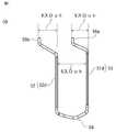
(3)ジョイントコイルの構成
図7は各相の固定子コイル12に1個ずつ含まれるジョイントコイル50を示す正面図である。(3) Configuration of Joint Coil FIG. 7 is a front view showing a
ジョイントコイル50は、1ターンのコイルであり、2つのスロット部つまり第1スロット部51および第2スロット部52を有している。第1スロット部51および第2スロット部52は、それぞれ1本の第4導体線51d、52dで構成されている。そして、これらの第4導体線51d、52dが第2コイルエンド部54により連結されている。この場合も、ジョイントコイル50の形状全体が固定子鉄心11の周方向に沿って円弧状に湾曲して形成される。 The
そして、第1スロット部51および第2スロット部52は、上記の第1分割コイル30および第2分割コイル40の場合と同様に、6スロット分(角度ピッチ:45°)の間隔を保って形成されている。 The
また、第4導体線51dの延長上の第1端末部55aは、当該第4導体線51dから周方向にVスロット分(角度ピッチ:7.5°×V)離れている。同様に、第4導体線52dの延長上の第2端末部55bは、当該第4導体線52dから周方向にVスロット分(角度ピッチ:7.5°×V)離れている。 In addition, the first
なお、第4導体線51dおよび52dは、先の図2に示したスロット15内の各導体線12a〜12dとの配置関係では、径方向の最も外周側に位置する第4導体線12dに対応している。 The
次に、このジョイントコイル50が固定子鉄心11のスロット15に配置される場合の第4導体線51dおよび52dとスロット15との互いの位置関係について、図8を用いて具体的に説明する。 Next, the positional relationship between the
図8は一つのジョイントコイル50が固定子鉄心11に配置された状態を示す模式図である。図8は、実際には円筒形である固定子鉄心11を直線状に展開したものであり、第1端末部55aおよび第2端末部55bが突出している側の軸方向から見た平面図である。なお、図8において、上方側が固定子鉄心11の内周側、下方側が外周側である。 FIG. 8 is a schematic view showing a state in which one
スロット15内に配置される第1スロット部51の第4導体線51dと第2スロット部52の第4導体線52dとは6スロット分離れて配置されている。また、2本の第4導体線51dおよび第4導体線52dを結ぶ第2コイルエンド部54は、第1端末部55aおよび第2端末部55bの突出している側とは反対側において、図中破線で示すように固定子鉄心11のバックヨーク11bの上に引き回された上で第4導体線51dおよび第4導体線52d同士を固定子鉄心11の軸方向の外部において互いに連結している。なお、この第2コイルエンド部54は、バックヨーク11bから径方向の外側にはみ出すことはない。 The
また、第1端末部55aは、第4導体線51dが配置されたスロット15の位置から固定子鉄心11の外部においてVスロット分だけ離れた箇所に位置する。同様に、第2端末部55bは、第4導体線52dが配置されたスロット15の位置から固定子鉄心11の外部において第1端末部55aとは周方向において同じ向きにVスロット分離れた箇所に位置する。 In addition, the first
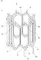
(4)固定子コイルの1相分の構成
図9は1相分の固定子コイルだけを表示し残りの他相分の固定子コイルを非表示とした場合の斜視図である。図9(a)は第1分割コイル30、第2分割コイル40、およびジョイントコイル50の端末部側(A側)を上にして見た斜視図である。図9(b)は第1分割コイル30、第2分割コイル40、およびジョイントコイル50の各端末部の配置側(A側)を下にして見た斜視図である。また、図10は図9(a)の状態において1相分の固定子コイルだけを表示し他相分の固定子コイルおよび固定子鉄心を非表示とした場合の斜視図である。(4) Configuration of One Phase of Stator Coil FIG. 9 is a perspective view in a case where only one phase of the stator coil is displayed and the remaining phase of the stator coil is not displayed. FIG. 9A is a perspective view of the
固定子10のスロット数をN、固定子コイル12の相数をPとすると、1相当たりのスロット数はN/Pであり(Nは2Pで割り切れる)、このとき、1相分の固定子コイル12は、第1分割コイル30が{(N/P)−2}個、第2分割コイル40が2個、ジョイントコイル50が1個で構成される。 Assuming that the number of slots of the
具体例として、この実施の形態1では48スロットで、6相の場合を前提として説明しているので、1相分の固定子コイル12は、第1分割コイル30が(N/P)−2=(48/6)−2=6個、第2分割コイル40が2個、ジョイントコイル50が1個で構成される。 As a specific example, in the first embodiment, 48 slots are described on the assumption of the case of six phases, so the
この場合、2ターンのコイルである第1分割コイル30は、第1スロット部31および第2スロット部32が固定子鉄心11の周方向に沿って6スロットおきに順次6つ配置されており、それに引き続いて1.5ターンのコイルである第2分割コイル40の第1スロット部41および第2スロット部42が周方向に沿って6スロットおきに2つ配置されている。 In this case, in the first divided
これにより、第2分割コイル40の第2スロット部42が配置された2箇所のスロット15には図2の第1導体線12a〜第3導体線12cまでが配置され、それ以外のスロット15には図2の第1導体線12a〜第4導体線12dまでが配置される。さらに第2分割コイル40の第2スロット部42、すなわち第2導体線42bが配置されたスロット15にはジョイントコイル50の第4導体線51d、52dがそれぞれ1つずつ配置される。これにより、各々のスロット15には図2に示したように4本の第1導体線12a〜第4導体線12dが配置される。 Thus, the
ジョイントコイル50は、第1分割コイル30および第2分割コイル40とは異なり、第2コイルエンド部54は第1および第2スロット部51、52から固定子鉄心11の軸方向外側において径方向外側に曲げられてバックヨーク11b上に配置される。 The
第1分割コイル30の第2コイルエンド部34および第2分割コイル40の第2コイルエンド部44は、それぞれ第3導体線31c、41cに繋がる形状であるが、ジョイントコイル50の第2コイルエンド部54は、上記の第3導体線31c、41cよりも外側に位置する第4導体線51d、52d同志を接続する形状であるため、ジョイントコイル50の第2コイルエンド部54の形状を、第1分割コイル30の第2コイルエンド部34または第2分割コイル40の第2コイルエンド部44の形状と同一にすることができない。 Although the second
すなわち、第1分割コイル30の第2コイルエンド部34および第2分割コイル40の第2コイルエンド部44は共に同一形状にすることで周方向に並べて配置することを可能としているが、ジョイントコイル50の第2コイルエンド部54は、第1分割コイル30の第2コイルエンド部34および第2分割コイル40の第2コイルエンド部44とは形状が異なるので混在させることができない。 That is, although the second
そのため、ジョイントコイル50の第2コイルエンド部54については、バックヨーク11b上に配置して他の第2コイルエンド部34、44との干渉を回避する。ただし、ジョイントコイル50の第2コイルエンド部54は固定子鉄心11のバックヨーク11bの上に引き回されるが、前述のように、バックヨーク11bから径方向外側にはみ出すことはない。 Therefore, the second
第2分割コイル40の第2端末部45bを除き、第1分割コイル30、第2分割コイル40、およびジョイントコイル50の全ての端末部が固定子10の軸方向の一方側(A側)に配置されるので、周方向において互いに隣接する2本の端末部を接合して1相分の固定子コイル12が構成される。また、2本の第2分割コイル40の第2端末部45bは1相分の固定子コイル12の両端末部となる。 Except for the
(5)端末部接合について
次に、1相分の固定子コイル12について、固定子10の軸方向の一方側(図9および図10のA側)における第1分割コイル30、第2分割コイル40およびジョイントコイル50の各端末部の接合の仕方について説明する。(5) End part joining Next, regarding the
固定子鉄心11に組み込まれた第1分割コイル30、第2分割コイル40およびジョイントコイル50の各端末部同士を直列に接合することにより、1相分の固定子コイルを構成する。この場合、各端末部同士の接合部は全て固定子鉄心11の周方向に沿った各端末部の形成位置の範囲内に収まり、内側鉄心11aやバックヨーク11bから径方向に向けてさらに膨らむことはない。 The respective ends of the
図10に示すように、互いに接合する端末部は、第1分割コイル30、第2分割コイル40およびジョイントコイル50の第3導体線31c、41cあるいは第4導体線32d、51d、52dの延長上に存在しており、それぞれ第3導体線31c、41cの延長上に存在する端末部35a、45aを6スロット分離れたスロット15に組み込んである第4導体線32d、51d、52dの延長上に存在する端末部35b、55a、55bと接合する。 As shown in FIG. 10, the end portions joined to each other are extensions of the
具体的には、第1分割コイル30の第1端末部35aは、これに隣接する他の第1分割コイル30の第2端末部35bに接続される。また、第2分割コイル40の存在箇所では、第2分割コイル40の第1端末部45aに第1分割コイル30の第2端末部35bが接合される。さらに、ジョイントコイル50の存在箇所では、ジョイントコイル50の第1端末部55aと第1分割コイル30の第1端末部35a、およびジョイントコイル50の第2端末部55bと第1分割コイル30の第1端末部35aとが接合される。 Specifically, the
互いに隣接する2つの端末部の接合には溶接またはハンダ付けといった方法が用いられるので、互いに接合する2つの端末部同士は互いに接触する位置まで近づける必要がある。そのため、互いに隣接する2つの端末部はスロット部からそれぞれ周方向にUスロット分(角度ピッチ:7.5°×U)とVスロット分(角度ピッチ:7.5°×V)だけ互いに逆方向に曲げられており、U+V=6スロット分(角度ピッチ:45°)となる。 Since methods such as welding or soldering are used to join two adjacent end portions, the two end portions joined to each other need to be brought close to a position where they contact each other. Therefore, two terminal parts adjacent to each other in the circumferential direction from the slot part are opposite to each other by U slots (angular pitch: 7.5 ° × U) and V slots (angular pitch: 7.5 ° × V). And U + V = 6 slots (angular pitch: 45 °).
このようにして固定子鉄心11の周方向に沿って曲げられた互いに隣接する2つの端末部同士の先端部を溶接またはハンダ付けで接合する。固定子10の軸方向の一端側(A側)においては、各端末部先端に接合部25が形成される。なお、全相の固定子コイルが組み込まれた状態ではスロット数と同数の接合部25が円周上に配置される(図12(a)参照)。 In this manner, the tips of two adjacent end portions bent along the circumferential direction of the
以上のように第1分割コイル30、第2分割コイル40およびジョイントコイル50を配置し、お互いの端末部を接続することにより、第1分割コイル30、第2分割コイル40およびジョイントコイル50を直列に接続できる。その場合、各端末部35a、35b、45a、55a、55bの接合箇所が第1分割コイル30、第2分割コイル40およびジョイントコイル50の第1コイルエンド部33、43と重なり合うことがないので、固定子10の軸方向の高さが低く抑えられる。 As described above, the
この実施の形態1では6相、48スロットで、各スロット15に径方向に沿って4本の導体線が配置されるので、この接続により(48/6)×4=32本の導体線が隣接スロットごとに通電方向が反対方向になるように直列に接続される。 In the first embodiment, four conductor wires are arranged in each
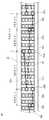
図11は、1相分の固定子コイル12を構成する9個のコイル、つまり6個の第1分割コイル30、2個の第2分割コイル40、および1個のジョイントコイル50の接続状態を模式的に表した図である。図11は、円筒状に配置された固定子コイル12を直線状に展開した状態を示した図であり、図11の左側のコイルR、S、T、Uはそれぞれ右側のコイルr、s、t、uにつながっている。図11において、細線の点線で示した長方形はそれぞれ6スロット離れたスロット15を表しており、各スロット15内に4本の導体線12a〜12dが配置されている。図11において、4本の導体線12a〜12dは、右端から第1導体線12a、第2導体線12b、第3導体線12c、第4導体線12dの順番に示している。 FIG. 11 shows the connection state of nine coils constituting the
上述したように、本実施の形態では、1相分の固定子コイル12は、6個の第1分割コイル30、2個の第2分割コイル40、および1個のジョイントコイル50で構成されている。図11において、第1分割コイル30を細い実線で示し、第2分割コイル40を太い実線で示し、ジョイントコイル50を太い点線で示している。6個の第1分割コイル30が連続して配置され、次に、1個のジョイントコイル50と2個の第2分割コイル40が配置される。なお、図11では、第1分割コイル30の1個を図の左右に分割して示している。 As described above, in the present embodiment, the
(6)全相の固定子コイルの構成
上記の6個の第1分割コイル30、2個の第2分割コイル40、1個のジョイントコイル50を組み合わせることで1相分の固定子コイル12を構成し、この1相分の固定子コイル12を6相分設けることで全相の固定子コイル12を構成する。(6) Configuration of Stator Coils of All Phases The stator coils 12 for one phase are combined by combining the six first split coils 30, two second split coils 40, and one
図12は全相の固定子コイル12を組み込んで固定子10を構成した場合の斜視図である。図12(a)は第1分割コイル30、第2分割コイル40およびジョイントコイル50の各端末部の配置側(A側)を上にして見た斜視図であり、図12(b)は第1分割コイル30、第2分割コイル40およびジョイントコイル50の各端末部の配置側(A側)を下にして見た斜視図である。 FIG. 12 is a perspective view when the
第1分割コイル30の第1端末部35aおよび第2端末部35b、第2分割コイル40の第1端末部45a、ジョイントコイル50の第1端末部55aおよび第2端末部55bは、全て固定子10の軸方向の一方側(A側)になるように配置される。この場合、前述のように、各端末部35a、35b、45a、55a、55bの接合箇所が第1分割コイル30の第1コイルエンド部33および第2分割コイル40の第1コイルエンド部43と重なり合うことがないので、固定子10の軸方向の高さを低減できる。また、固定子10の軸方向の一方側(A側)とは反対側には、第1分割コイル30の第2コイルエンド部34、ジョイントコイル50の第2コイルエンド部54、第2分割コイル40の第2コイルエンド部44が並んで配置され、その間から第2分割コイル40の第2端末部45bが軸方向外方に突出している。 The
なお、この実施の形態1では、ジョイントコイル50の第2コイルエンド部54がスロット15の外周側のバックヨーク11bの上に配置されている。その際、バックヨーク11bの径方向の幅に余裕がない場合、フレーム3とジョイントコイル50との距離が十分に確保できないことが起こる。また、フレーム3に固定子10を圧入等の方法によって組み込む場合に、固定子鉄心11を支持するスペースが十分ではないことが起こり得る。 In the first embodiment, the second
しかし、バックヨーク11bの上に配置されるのはジョイントコイル50の第2コイルエンド部54だけであり、その場合、第2コイルエンド部54が固定子鉄心11のバックヨーク11bから径方向の外側にはみ出すことはなく、しかも、第2コイルエンド部54は絶縁被膜を有しているので、フレーム3との絶縁性を十分に確保可能である。 However, only the second
また、固定子10の内周側には回転子20が配置されるため、固定子10を構成するための第1分割コイル30、第2分割コイル40およびジョイントコイル50からなる固定子コイル12の各コイルエンド部33、34、43、44、54は、回転子20の外周よりも径方向外側に位置しなければならない。各コイルエンド部33、34、43、44、54が回転子20の外周よりも径方向内側に位置する場合には、回転子20の組込みができなくなる。この実施の形態1の場合、端末部同士を接合している側(図12(a)のA側)の各コイルエンド部33、34、43、44、54は、回転子20の外周よりも径方向内側にはみ出すことがないため、回転子20の組み込みには問題ない。 Further, since the
実施の形態1の展開例.
なお、この実施の形態1において、回転電機の固定子10は、6相、48スロットであり、図2に示したように各スロット15に4本の第1〜第4導体線12a〜12dが配置される場合について説明したが、固定子の相数やスロット数の値が異なっていても同様の接続方法を採用することが可能である。Deployment example of the first embodiment.
In the first embodiment, the
例えば、6相ではなく5相の場合には、各分割コイルのスロット部の配置間隔が5スロット分となり、各端末部の曲げがU+V=5スロット分となる。また、スロット数が48スロットではなく60スロットの場合には、固定子コイル12を構成する分割コイルのうち、第1分割コイル30の数が多くなる。すなわち、60スロットの場合、1相分の固定子コイルは、8個の第1分割コイル30、2個の第2分割コイル40、1個のジョイントコイル50で構成される。 For example, in the case of five phases instead of six phases, the arrangement interval of the slot portion of each split coil is five slots, and the bending of each end portion is U + V = 5 slots. When the number of slots is not 48 but 60, the number of first split coils 30 among the split coils constituting the
また、上記の実施の形態1では、第1分割コイル30として、ターン数をMとすると、M=2のコイルを使用したが、ターン数Mはこれに限定されるものではなく、一般化して次のように考えることができる。 Further, in the above-described first embodiment, assuming that the number of turns is M as the first divided
すなわち、第1分割コイル30としては、Mターン(Mは2以上の整数)以上のコイルであってもよく、この場合、この第1分割コイル30は、固定子鉄心11の径方向において第1導体線から第(2×M)導体線までの(2×M)本の導体線がスロット15に配置されるとともに、第(2×M−1)導体線と第(2×M)導体線からそれぞれスロット15の外部に引き出される第1端末部35aと第2端末部35bが形成された構成となる。また、この第1分割コイル30の構成に適合するように、第2分割コイル40は、第1分割コイル30から0.5ターン減じた巻数のコイルであって、固定子鉄心11の径方向において第1導体線、第2導体線、第(2×M−1)導体線としてスロット15に配置されるとともに、第(2×M−1)導体線からスロット15の外部に引き出される第1端末部45aが形成された構成となる。さらに、ジョイントコイル50については、固定子鉄心11の径方向において第(2×M)導体線としてスロット15に配置されるとともに、第(2×M)導体線の両端部からそれぞれスロット15の外部に引き出される第1端末部55aと第2端末部55bが形成された構成となる。 That is, the
また、この発明は、上記の実施の形態1の構成のみに限定されるものではなく、この発明の趣旨を逸脱しない範囲において、この実施の形態1の構成の一部に変形を加えたり、構成の一部を省略することが可能である。 Further, the present invention is not limited to only the configuration of the first embodiment described above, and a part of the configuration of the first embodiment may be modified or a configuration without departing from the spirit of the present invention. It is possible to omit part of
Claims (3)
Translated fromJapanese各相の上記固定子コイルは、
Mターン(Mは2以上の整数)以上のコイルであって、上記固定子鉄心の径方向において第1導体線から第(2×M)導体線までの(2×M)本の導体線が上記スロットに配置されるとともに、第(2×M−1)導体線と第(2×M)導体線からそれぞれ上記スロットの外部に引き出される第1端末部と第2端末部が形成された第1分割コイルと、
上記第1分割コイルから0.5ターン減じた巻数のコイルであって、上記固定子鉄心の径方向において第1導体線、第2導体線、第(2×M−1)導体線として上記スロットに配置されるとともに、上記第(2×M−1)導体線から上記スロットの外部に引き出される第1端末部が形成された第2分割コイルと、
1ターンのコイルであって、上記固定子鉄心の径方向において第(2×M)導体線として上記スロットに配置されるとともに、上記第(2×M)導体線の両端部からそれぞれ上記スロットの外部に引き出される第1端末部と第2端末部が形成されたジョイントコイルと、
を組み合わせ、上記第1分割コイルの上記第1端末部および上記第2端末部、上記第2分割コイルの上記第1端末部、並びに上記ジョイントコイルの上記第1端末部および上記第2端末部を選択的に接合して構成されている回転電機の固定子。The stator coil has an annular stator core formed with a plurality of slots for housing the stator coils, and the stator coils housed in the slots are configured by connecting a plurality of divided coils for each phase. The stator of the rotating electrical machine being
The stator coil of each phase is
A coil of M turns (M is an integer of 2 or more) or more, and (2 × M) conductor wires from the first conductor wire to the (2 × M) conductor wire in the radial direction of the stator core are A first terminal portion and a second terminal portion which are disposed in the slot and which are respectively drawn out of the slot from the second (2 × M−1) conductor line and the second (2 × M) conductor line With one division coil,
A coil having a number of turns reduced by 0.5 turns from the first divided coil, wherein the slots as the first conductor wire, the second conductor wire, and the second (2 × M-1) conductor wire in the radial direction of the stator core A second split coil formed on the first end portion which is disposed outside the slot and is disposed from the second (2 × M−1) conductor wire;
The coil of one turn is disposed in the slot as a second (2 × M) conductor wire in the radial direction of the stator core, and from both ends of the second (2 × M) conductor wire, respectively. A joint coil formed with a first end portion and a second end portion which are drawn out to the outside;
And combining the first end and the second end of the first divided coil, the first end of the second divided coil, and the first and second ends of the joint coil. A stator of a rotating electrical machine configured to be selectively joined.
Applications Claiming Priority (3)
| Application Number | Priority Date | Filing Date | Title |
|---|---|---|---|
| JP2016119449 | 2016-06-16 | ||
| JP2016119449 | 2016-06-16 | ||
| PCT/JP2017/020814WO2017217271A1 (en) | 2016-06-16 | 2017-06-05 | Stator for rotary electric machine |
Publications (2)
| Publication Number | Publication Date |
|---|---|
| JPWO2017217271A1 JPWO2017217271A1 (en) | 2018-08-30 |
| JP6545381B2true JP6545381B2 (en) | 2019-07-17 |
Family
ID=60663154
Family Applications (1)
| Application Number | Title | Priority Date | Filing Date |
|---|---|---|---|
| JP2018523670AExpired - Fee RelatedJP6545381B2 (en) | 2016-06-16 | 2017-06-05 | Stator of rotating electric machine |
Country Status (3)
| Country | Link |
|---|---|
| US (1) | US10756588B2 (en) |
| JP (1) | JP6545381B2 (en) |
| WO (1) | WO2017217271A1 (en) |
Families Citing this family (2)
| Publication number | Priority date | Publication date | Assignee | Title |
|---|---|---|---|---|
| CN111614183A (en)* | 2020-06-19 | 2020-09-01 | 天津市松正电动汽车技术股份有限公司 | A flat wire vertical winding motor winding, motor stator and flat wire vertical winding motor |
| JP7688505B2 (en)* | 2021-03-31 | 2025-06-04 | 株式会社Subaru | Rotating Electric Machine |
Family Cites Families (5)
| Publication number | Priority date | Publication date | Assignee | Title |
|---|---|---|---|---|
| US7969058B2 (en)* | 2007-06-07 | 2011-06-28 | GM Global Technology Operations LLC | Permanent magnet motor with stator having asymmetric slots for reducing torque ripple |
| US9531227B2 (en)* | 2012-03-29 | 2016-12-27 | Honda Motor Co., Ltd. | Stator structure for rotary electric machine |
| JP6022896B2 (en)* | 2012-10-29 | 2016-11-09 | 日立オートモティブシステムズ株式会社 | Rotating electric machine |
| WO2015029579A1 (en) | 2013-08-26 | 2015-03-05 | 三菱電機株式会社 | Rotary electrical machine |
| WO2015162643A1 (en)* | 2014-04-24 | 2015-10-29 | 三菱電機株式会社 | Stator of rotary electrical machine and rotary electrical machine using such stator |
- 2017
- 2017-06-05USUS16/308,743patent/US10756588B2/ennot_activeExpired - Fee Related
- 2017-06-05WOPCT/JP2017/020814patent/WO2017217271A1/ennot_activeCeased
- 2017-06-05JPJP2018523670Apatent/JP6545381B2/ennot_activeExpired - Fee Related
Also Published As
| Publication number | Publication date |
|---|---|
| US20190260251A1 (en) | 2019-08-22 |
| WO2017217271A1 (en) | 2017-12-21 |
| JPWO2017217271A1 (en) | 2018-08-30 |
| US10756588B2 (en) | 2020-08-25 |
Similar Documents
| Publication | Publication Date | Title |
|---|---|---|
| US9472988B2 (en) | Rotary electric machine and method of manufacturing the same | |
| JP6120987B2 (en) | Armature of electric machine | |
| JP6058146B2 (en) | Rotating electric machine | |
| JP5496154B2 (en) | Outer rotor type stator structure | |
| JP6261809B2 (en) | Stator and rotating electric machine | |
| JP5376016B1 (en) | Rotating electric machine | |
| JP6044382B2 (en) | Multi-gap rotating electric machine | |
| JP5516989B2 (en) | Armature for rotating electrical machine | |
| US20230369921A1 (en) | Stator and motor | |
| US20220263356A1 (en) | Motor | |
| JP4286829B2 (en) | Manufacturing method of rotating machine | |
| JP2018088729A (en) | Rotating electric machine stator | |
| JP2022187869A (en) | motor | |
| JP2007159170A5 (en) | ||
| JP6545381B2 (en) | Stator of rotating electric machine | |
| EP1341288B1 (en) | Electric rotary machine | |
| JP5036442B2 (en) | Stator and stator manufacturing method | |
| JP2022151966A (en) | stator and motor | |
| JP2019037103A (en) | Stator and motor | |
| JP2020150753A (en) | Stator and brushless motor | |
| JP2020022249A (en) | Stator and brushless motor | |
| JP2004096992A (en) | Stator of adduction motor and method of manufacturing the same | |
| JP2019205230A (en) | Rotary electric machine stator manufacturing method | |
| JP2015019452A (en) | Coil and coil formation method | |
| US11569700B2 (en) | Rotating electric machine |
Legal Events
| Date | Code | Title | Description |
|---|---|---|---|
| A621 | Written request for application examination | Free format text:JAPANESE INTERMEDIATE CODE: A621 Effective date:20180509 | |
| TRDD | Decision of grant or rejection written | ||
| A01 | Written decision to grant a patent or to grant a registration (utility model) | Free format text:JAPANESE INTERMEDIATE CODE: A01 Effective date:20190521 | |
| A61 | First payment of annual fees (during grant procedure) | Free format text:JAPANESE INTERMEDIATE CODE: A61 Effective date:20190618 | |
| R150 | Certificate of patent or registration of utility model | Ref document number:6545381 Country of ref document:JP Free format text:JAPANESE INTERMEDIATE CODE: R150 | |
| R250 | Receipt of annual fees | Free format text:JAPANESE INTERMEDIATE CODE: R250 | |
| LAPS | Cancellation because of no payment of annual fees |