JP6545229B2 - IMAGE PROCESSING APPARATUS, IMAGING APPARATUS, CONTROL METHOD OF IMAGE PROCESSING APPARATUS, AND PROGRAM - Google Patents
IMAGE PROCESSING APPARATUS, IMAGING APPARATUS, CONTROL METHOD OF IMAGE PROCESSING APPARATUS, AND PROGRAMDownload PDFInfo
- Publication number
- JP6545229B2 JP6545229B2JP2017160568AJP2017160568AJP6545229B2JP 6545229 B2JP6545229 B2JP 6545229B2JP 2017160568 AJP2017160568 AJP 2017160568AJP 2017160568 AJP2017160568 AJP 2017160568AJP 6545229 B2JP6545229 B2JP 6545229B2
- Authority
- JP
- Japan
- Prior art keywords
- image
- motion vector
- area
- processed
- detected
- Prior art date
- Legal status (The legal status is an assumption and is not a legal conclusion. Google has not performed a legal analysis and makes no representation as to the accuracy of the status listed.)
- Expired - Fee Related
Links
Images


Classifications
- H—ELECTRICITY
- H04—ELECTRIC COMMUNICATION TECHNIQUE
- H04N—PICTORIAL COMMUNICATION, e.g. TELEVISION
- H04N19/00—Methods or arrangements for coding, decoding, compressing or decompressing digital video signals
- H04N19/10—Methods or arrangements for coding, decoding, compressing or decompressing digital video signals using adaptive coding
- H04N19/134—Methods or arrangements for coding, decoding, compressing or decompressing digital video signals using adaptive coding characterised by the element, parameter or criterion affecting or controlling the adaptive coding
- H04N19/136—Incoming video signal characteristics or properties
- H04N19/137—Motion inside a coding unit, e.g. average field, frame or block difference
- H04N19/139—Analysis of motion vectors, e.g. their magnitude, direction, variance or reliability
- G—PHYSICS
- G06—COMPUTING OR CALCULATING; COUNTING
- G06T—IMAGE DATA PROCESSING OR GENERATION, IN GENERAL
- G06T7/00—Image analysis
- G06T7/30—Determination of transform parameters for the alignment of images, i.e. image registration
- G06T7/33—Determination of transform parameters for the alignment of images, i.e. image registration using feature-based methods
- G06T7/337—Determination of transform parameters for the alignment of images, i.e. image registration using feature-based methods involving reference images or patches
- G—PHYSICS
- G06—COMPUTING OR CALCULATING; COUNTING
- G06T—IMAGE DATA PROCESSING OR GENERATION, IN GENERAL
- G06T7/00—Image analysis
- G06T7/70—Determining position or orientation of objects or cameras
- G06T7/73—Determining position or orientation of objects or cameras using feature-based methods
- H—ELECTRICITY
- H04—ELECTRIC COMMUNICATION TECHNIQUE
- H04N—PICTORIAL COMMUNICATION, e.g. TELEVISION
- H04N23/00—Cameras or camera modules comprising electronic image sensors; Control thereof
- H04N23/60—Control of cameras or camera modules
- H—ELECTRICITY
- H04—ELECTRIC COMMUNICATION TECHNIQUE
- H04N—PICTORIAL COMMUNICATION, e.g. TELEVISION
- H04N23/00—Cameras or camera modules comprising electronic image sensors; Control thereof
- H04N23/60—Control of cameras or camera modules
- H04N23/698—Control of cameras or camera modules for achieving an enlarged field of view, e.g. panoramic image capture
- H—ELECTRICITY
- H04—ELECTRIC COMMUNICATION TECHNIQUE
- H04N—PICTORIAL COMMUNICATION, e.g. TELEVISION
- H04N23/00—Cameras or camera modules comprising electronic image sensors; Control thereof
- H04N23/80—Camera processing pipelines; Components thereof
- G—PHYSICS
- G06—COMPUTING OR CALCULATING; COUNTING
- G06T—IMAGE DATA PROCESSING OR GENERATION, IN GENERAL
- G06T2200/00—Indexing scheme for image data processing or generation, in general
- G06T2200/32—Indexing scheme for image data processing or generation, in general involving image mosaicing
- G—PHYSICS
- G06—COMPUTING OR CALCULATING; COUNTING
- G06T—IMAGE DATA PROCESSING OR GENERATION, IN GENERAL
- G06T2207/00—Indexing scheme for image analysis or image enhancement
- G06T2207/20—Special algorithmic details
- G06T2207/20021—Dividing image into blocks, subimages or windows
Landscapes
- Engineering & Computer Science (AREA)
- Multimedia (AREA)
- Signal Processing (AREA)
- Computer Vision & Pattern Recognition (AREA)
- Physics & Mathematics (AREA)
- General Physics & Mathematics (AREA)
- Theoretical Computer Science (AREA)
- Studio Devices (AREA)
- Image Analysis (AREA)
- Stereoscopic And Panoramic Photography (AREA)
- Image Processing (AREA)
- Editing Of Facsimile Originals (AREA)
Description
Translated fromJapanese本発明は、画像処理装置に関するものであり、特に複数の画像に対して位置合わせを行う画像処理装置に関するものである。 The present invention relates to an image processing apparatus, and more particularly to an image processing apparatus that performs alignment on a plurality of images.
デジタルカメラやカメラ機能付きの携帯電話などを移動させながら複数の画像を撮像し、撮像した複数の画像を繋ぎ合わせることによるパノラマ合成の技術が知られている。 2. Description of the Related Art There is known a technique of panoramic synthesis by capturing a plurality of images while moving a digital camera, a mobile phone with a camera function, and the like, and connecting the captured plurality of images.
特許文献1では、画像から動きベクトルを検出し、検出した動きベクトルに基づいて位置合わせを行う技術が開示されている。 Patent Document 1 discloses a technique for detecting a motion vector from an image and performing alignment based on the detected motion vector.
しかしながら、被写体によっては動きベクトルの検出が困難な場合があり、動きベクトルを検出できたとしても、その動きベクトルが必ずしも正しい情報であるとは限らない。誤って検出された動きベクトルを用いて位置合わせを行ってしまうと、被写体の位置にズレが生じたパノラマ合成が行われてしまう。 However, depending on the subject, it may be difficult to detect a motion vector, and even if a motion vector can be detected, the motion vector is not necessarily correct information. If alignment is performed using a motion vector detected erroneously, panoramic combination in which the position of the object is shifted is performed.
本発明は、上記の課題を鑑みてなされたものであり、複数の画像間の位置合わせ精度の高いパノラマ画像を作成することを目的とする。 The present invention has been made in view of the above problems, and an object thereof is to create a panoramic image with high alignment accuracy among a plurality of images.
本発明は、複数の画像から動きベクトルを検出する検出手段と、前記複数の画像の少なくとも一部を用いて合成を行い、パノラマ画像を生成する合成手段と、を有し、前記検出手段は、処理対象の画像の第1の領域、および、前記第1の領域よりも狭い第2の領域から動きベクトルを検出し、前記合成手段は、前記第1の領域から検出した動きベクトルと前記第2の領域から検出した動きベクトルとの差が所定範囲内であれば、前記処理対象の画像を前記合成に用いることを特徴とする画像処理装置を提供する。 The present invention includes a detection unit that detects a motion vector from a plurality of images, and a combination unit that performs synthesis using at least a part of the plurality of images to generate a panoramic image, and the detection unit includes: A motion vector is detected from a first area of an image to be processed and a second area narrower than the first area, and the combining means includes the motion vector detected from the first area and the second area. The image processing apparatus is characterized in that the image to be processed is used for the combination if the difference between the motion vector and the motion vector detected from the region is within a predetermined range.
本発明によれば、複数の画像間の位置合わせ精度の高いパノラマ画像を作成できる。 According to the present invention, it is possible to create a panoramic image with high alignment accuracy among a plurality of images.
以下では、添付の図面を参照しながら、本発明の好適な実施形態について詳細に説明する。 Hereinafter, preferred embodiments of the present invention will be described in detail with reference to the accompanying drawings.
(第1の実施形態)
図1は本実施形態に係るデジタルカメラの構造を示すブロック図である。デジタルカメラ100は、静止画を撮像することができ、かつ、合焦位置の情報を記録し、コントラスト値の算出および画像の合成が可能なものである。さらに、デジタルカメラ100は、撮像して保存した画像、または、外部から入力した画像に対して、拡大処理または縮小処理を行うことができる。First Embodiment
FIG. 1 is a block diagram showing the structure of a digital camera according to the present embodiment. The digital camera 100 can capture a still image, can record information on the in-focus position, and can calculate contrast values and combine images. Furthermore, the digital camera 100 can perform enlargement processing or reduction processing on an image captured and stored or an image input from the outside.
制御部101は、例えばCPUやMPUなどのシグナルプロセッサであり、予め後述するROM105に内蔵されたプログラムを読み出しながら、デジタルカメラ100の各部分を制御する。たとえば、後述するように、制御部101が、後述する撮像部104に対して撮像の開始と終了について指令を出す。または、後述する画像処理部107に対して、ROM105に内蔵されたプログラムに基づいて、画像処理の指令を出す。ユーザによる指令は、後述する操作部110によってデジタルカメラ100に入力され、制御部101を通して、デジタルカメラ100の各部分に達する。 The
駆動部102は、モーターなどによって構成され、制御部101の指令の下で、後述する光学系103を機械的に動作させる。たとえば、制御部101の指令に基づいて、駆動部102が光学系103に含まれるフォーカスレンズの位置を移動させ、光学系103の焦点距離を調整する。 The
光学系103は、ズームレンズ、フォーカスレンズ、および絞りなどにより構成される。絞りは、透過する光量を調整する機構である。レンズの位置を変えることによって、合焦位置を変えることができる。 The
撮像部104は、光電変換素子であり、入射された光信号を電気信号に変換する光電変換を行うものである。たとえば、撮像部104に、CCDセンサやCMOSセンサなどを適用することができる。撮像部104は、動画撮像モードを設け、時間的に連続する複数の画像を動画の各々のフレームとして、撮像することができる。 The
ROM105は、記録媒体としての読み出し専用の不揮発性メモリであり、デジタルカメラ100が備える各ブロックの動作プログラムに加え、各ブロックの動作に必要なパラメータ等を記憶している。RAM106は、書き換え可能な揮発性メモリであり、デジタルカメラ100が備える各ブロックの動作において出力されたデータの一時的な記憶領域として用いられる。 The
画像処理部107は、撮像部104から出力された画像、あるいは後述する内蔵メモリ109に記録されている画像信号のデータに対して、ホワイトバランス調整、色補間、フィルタリングなど、様々な画像処理を行う。また、撮像部104が撮像した画像信号のデータに対して、JPEGなどの規格で、圧縮処理を行う。 An
画像処理部107は、特定の処理を行う回路を集めた集積回路(ASIC)で構成される。あるいは、制御部101がROM105から読み出したプログラムに従って処理することで、制御部101が画像処理部107の機能の一部または全部を兼用するようにしてもよい。制御部101が画像処理部107の全ての機能を兼用する場合には、画像処理部107をハードウェアとして有する必要はなくなる。 The
表示部108は、RAM106に一時保存されている画像、または、後述する内蔵メモリ109に保存されている画像、あるいは、デジタルカメラ100の設定画面などを表示するための液晶ディスプレイや有機ELディスプレイなどである。 The
内蔵メモリ109は、撮像部104が撮像した画像や画像処理部107の処理を得た画像、および、画像撮像時の合焦位置の情報などを記録する場所である。内蔵メモリの代わりに、メモリカードなどを用いてもよい。 The built-in
操作部110は、たとえば、デジタルカメラ100につけるボタンやスイッチ、キー、モードダイアルなど、あるいは、表示部108に兼用されるタッチパネルなどである。ユーザによる指令は、操作部110を経由して、制御部101に達する。 The
装置動き検出部111はジャイロセンサによって構成され、デジタルカメラ100の動きを検出するデバイスであり、デジタルカメラ100の単位時間当たりの角度変化、すなわち角速度に基づいてヨー方向とピッチ方向の動きを検出する。 The device
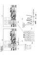
図2は、本発明の実施形態に係るパノラマ画像の合成処理の流れを説明する図である。図2では、ドットハッチングされた領域は、被写界にある並木を模式的に表した領域であり、斜線ハッチングされた領域は、画像データの切り出し領域を表している。図2(a)は、ユーザが操作部110に設けたボタンを押下し、ユーザは、主被写体に対してピント合わせを行うことを示している。図4(b)は、ユーザが合成しようとしているパノラマ画像の一方の端に合わせて画角を設定している。図4(b)では、撮像部104は画像210を撮像する。図2(c)乃至図2(e)では、ユーザが合成しようとしているパノラマ画像の他方の端に向けてデジタルカメラ100を移動させながら、パノラマ撮像を行っている状態を模式的に示している。図2(e)は、ユーザがボタンの押下をやめ、パノラマ撮像が終了した状態を示している。図2(b)乃至図2(e)では、撮像部104が画像210乃至270計7枚の画像を撮像したが、画像230、250および260は不図示である。画像処理部107は、撮像部104が撮像した画像210乃至270に対して切り出し処理を行い、切り出し領域211乃至271を生成する。制御部101において、切り出し領域の幅は、予め定めてもよいが、パノラマ撮像中のデジタルカメラ100の移動速度などに応じて変化させてもよい。 FIG. 2 is a diagram for explaining the flow of panoramic image combining processing according to the embodiment of the present invention. In FIG. 2, the dot-hatched area is an area schematically representing a row of trees in the field, and the hatched area represents a cutout area of the image data. FIG. 2A shows that the user presses a button provided on the
図2(f)は、画像処理部107が、撮像部104が撮像した複数の画像を合成してできたパノラマ画像を示している。ここで、制御部101は、合成を行う前に、画像に対して位置合わせを行う。また、手振れなどのため、切り出し領域211乃至271の上辺と下辺とは合っていないため、画像処理部107は、縦方向に対しても切り出し処理を行う。その結果、画像処理部107は、領域200が示したようなパノラマ画像を生成する。 FIG. 2F shows a panoramic image formed by combining the plurality of images captured by the
制御部101は、画像処理部107が検出した複数の動きベクトルに基づいて、位置合わせを行う。一例としては、画像処理部107は、切り出し領域を任意のサイズの小ブロックに分割し、小ブロック毎に輝度の差分絶対値和(Sum of Absolute Difference、以下、SADという)が最小となる対応点を算出する。制御部101は、算出したSADが最小となる対応点より、動きベクトルを算出することができる。制御部101は、SADの他に、差分二乗和(Sum of Squared Difference、以下SSDという)や正規化相互相関(Normalized Cross Correlation、以下NCCという)などを用いてもよい。 The
図2では、説明を容易にするため、切り出し領域211乃至271の互いに重畳する領域がなく、かつ、互いに隣接している例を示している。もし、重畳する領域が存在していれば、重畳する領域の中央を境目として、画像処理部107は、その左側に片方の切り出し領域、右側にもう片方の切り出し領域の画素情報を合成画像に出力する。もしくは、画像処理部107は、境目上に両方の切り出し領域の画素情報を50%ずつ合成した値を出力し、境目からの距離が離れるに従って境目の左側では片方の切り出し領域を、境目の右側ではもう片方の切り出し領域の割合を大きくしながら合成を行う。 In FIG. 2, in order to facilitate the description, an example is shown in which there are no overlapping regions of the
なお、図2では、各々の画像において切り出し領域は画像の異なる位置に設定され、切り出し領域のサイズも異なるが、一般的に、歪などを考慮し、画像処理部107は、各々の画像の中央に、等しいサイズを持つ領域を切り出す。 In FIG. 2, although the cutout area in each image is set to a different position of the image and the size of the cutout area is also different, generally, in consideration of distortion etc., the
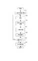
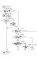
図3は、本実施形態におけるパノラマ画像の撮像処理を説明するためのフローチャートである。 FIG. 3 is a flowchart for explaining the imaging process of a panoramic image in the present embodiment.
ステップS301で、撮像部104が1枚目の画像の撮像を行う。また、このステップにおいて、画像処理部107が現像処理も行うが、簡略化のためフローチャートに記載していない。 In step S301, the
ステップS302で、撮像部104が2枚目以降の画像の撮像を行う。 In step S302, the
ステップS303では、制御部101はステップS302で撮像部302が撮像した処理対象の画像に対して動きベクトルの評価を行い、「高」「低」どちらかのフラグを設定する。詳細は後述する。 In step S303, the
ステップS304では、制御部101は、ステップS303の動きベクトルの評価の結果に基づいて画像の合成を行う。詳細は後述する。 In step S304, the
ステップS305では、制御部101が、ステップS304で制御部101が合成に用いると判断した隣り合う2枚の画像の間の移動量の算出を行う。ここでの移動量の算出は、パノラマ撮像の継続が可能であるかどうかの判断のためのものである。算出された移動量が画像の画角よりも広いのであれば、こうした画像を合成に用いると、被写体が映らない隙間が生じる可能性があるので、パノラマ撮像を中断することが好ましい。 In step S305, the
図4は、本実施形態における移動量の算出を説明するための図である。たとえば、パノラマ画像を作成するときに、円筒上に張り付ける円筒変換を行う場合、図4を参照し、回転角の最大値は下記の(式1)で算出できる。 FIG. 4 is a diagram for explaining the calculation of the movement amount in the present embodiment. For example, when performing cylindrical conversion pasted on a cylinder when creating a panoramic image, referring to FIG. 4, the maximum value of the rotation angle can be calculated by the following (Expression 1).

ただし、(式1)では、γは最大回転角で、fが焦点距離で、μがセンサの画素ピッチである。ここで、焦点距離fは一般的に、mmを単位とするが、センサの画素ピッチμはμmを単位とするので、計算するときは、単位を統一にする必要がある。そして、aは検出領域のブロックのサイズであり、bはデジタルカメラ100の移動方向でのブロックの数である。検出領域とブロックとの詳細については後述の動きベクトルの評価の説明のところで説明する。 However, in (Expression 1), γ is the maximum rotation angle, f is the focal length, and μ is the pixel pitch of the sensor. Here, although the focal length f is generally in units of mm, the pixel pitch μ of the sensor is in units of μm, so when calculating, it is necessary to unify the units. Further, a is the size of the block in the detection area, and b is the number of blocks in the moving direction of the digital camera 100. Details of the detection area and the block will be described in the description of motion vector evaluation described later.
なお、上記回転角度計算は、円筒変換の手法を用いた場合の例であるが、パノラマ画像の作成方法を限定するものではない。 In addition, although the said rotation angle calculation is an example at the time of using the method of cylindrical conversion, it does not limit the creation method of a panoramic image.
ステップS306で、制御部101が、撮像が終了するかどうかについて判断し、撮像が終了する場合はステップS307に進み、撮像が終了していない場合はステップS302に戻る。撮像の終了の判断基準は、たとえば、ユーザの手動での終了指示や、予め設定した画角に到達するなどが挙げられる。 In step S306, the
ステップS307で、制御部101は、撮像の終了時の処理を行う。ここでいう終了時の処理とは、主に表示部108を通じてユーザに撮像の結果の提示や、後述するような合成が失敗したときのエラー表示などを指す。 In step S307, the
以上では、本実施形態における撮像の流れを説明した。次に、ステップS303での動きベクトルの評価、およびステップS304での画像の合成の詳細について説明する。 The flow of imaging in the present embodiment has been described above. Next, details of motion vector evaluation in step S303 and image combination in step S304 will be described.
図5は、本実施形態における動きベクトルの評価処理を説明するためのフローチャートである。ステップS501で、制御部101は、直前に撮像した2枚の画像のうち先に撮像されたものの一部の領域を、検出領域と設定する。歪などを考慮し、制御部101が、検出領域を画像の中央に設定することが好ましい。ステップS502で、制御部101は、動きベクトルの検出を行う。制御部101は、まず、ステップS501で設定した検出領域に、複数の小ブロックを設定する。各々の小ブロックを同じサイズに設定することが好ましい。そこで、制御部101は、一方の画像に設定された複数の小ブロックのいずれかを選択し、他方の画像において、この選択した小ブロックと同じ位置であって、かつ、この小ブロックより広い検出領域を設定する。制御部101は、他方の画像の検出領域の中で、一方の画像の選択した小ブロックと最も相関が高くなる(SADの値が最小となる)領域を抽出する。ここでいう相関の計算では、たとえば、SAD、SSDやNCCなどを用いてもよい。 FIG. 5 is a flowchart for explaining motion vector evaluation processing in the present embodiment. In step S501, the
ステップS503では、ステップS502で、動きベクトルの検出が成功したかどうかについて判断する。制御部101は、動きベクトルの検出に成功したかどうかについては、以下の条件で判断する。たとえば、動きベクトルの検出領域が低コントラストであると、制御部101はSAD、SSDやNCCのいずれかを使っても正確性の高い動きベクトルを得にくい。したがって、ここで制御部101は、予め定められたコントラストの閾値より低いコントラストを持つ領域から検出した動きベクトルは、検出に成功していないと判断する。または、ステップS302での画像の撮像と同時に、装置動き検出部111は、デジタルカメラ100の角速度などの動き情報を検出する。制御部101は、装置動き検出部111が検出した動き情報とステップS502で検出した動きベクトルとを比較し、動き情報と動きベクトルとの差分が所定値を超えると、動きベクトルの検出に成功していないと判断する。 In step S503, it is determined in step S502 whether the motion vector detection has succeeded. The
ステップS503で、制御部101は、検出に成功したと判断された動きベクトルが所定数以上である場合はステップS504に進み、そうでない場合はステップS510に進む。ステップS510で、制御部101は、動きベクトルの評価のフラグを「低」に設定する。 In step S503, the
ステップS504で、制御部101は、ステップS501で設定した検出領域に、繰り返しパターンが存在するかどうかについて判断する。繰り返しパターンが存在する場合、ステップS510に進み、制御部101は、動きベクトルの評価のフラグを「低」に設定する。繰り返しパターンが存在しない場合、ステップS505に進む。 In step S504, the
繰り返しパターンのある画像では、デジタルカメラを動かしても似たような画像が映るため、制御部101がSAD、SSD、NCCのいずれの方法用いたとしても、検出した動きベクトルの誤差が大きくなる可能性が高い。図6は、画像に繰り返しパターンが存在する場合を説明するための図である。制御部101が、図6(a)と図6(b)に示した2枚の画像に対して動きベクトルの検出を行ったものとして説明する。図6(a)と図6(b)とに示した2枚の画像では、ビルの窓にあたるところが繰り返しパターンに相当する。たとえば、制御部101は、小領域601から動きベクトルを検出しようとする。制御部101は、小領域601のうちの中央にある領域をテンプレート602とし、図6(b)に示した画像の小領域603を検出範囲とし、小領域603からテンプレート602との相関が最も大きい所を検出する。前述したように、制御部101は、輝度のSAD、SSDやNCCのいずれかの方法を使ってもよく、以下では輝度のSADを例として説明する。制御部101は、検出範囲の小領域603に、テンプレート602のサイズに相当する範囲を設定し、その位置を少しずつずらしながら、テンプレート702とその範囲のSADを計算する。水平方向において、水平座標とSADとの関係は、図6(d)に示したようであり、その最小値が2つあるとわかる。これは、図6(c)に示したように、領域604と領域605とともに、テンプレート602と同様な図案が現れたためである。したがって、検出領域に繰り返しパターンが存在する場合、たとえ制御部101は成功に動きベクトルを検出できたとしても、位置合わせの精度が低くなる可能性が高い。 If the image has a repetitive pattern, similar images will appear even if you move the digital camera, so even if the
ステップS505で、制御部101は、ステップS503で検出に成功したと判断された動きベクトルの分布が不均一であるかどうかについて判断する。一般的に、動きベクトルは、検出領域の全体において均一に分布した方が、位置合わせの精度が高いとされている。逆に、成功に検出した動きベクトルは検出領域の一部にしか存在しないときは、位置合わせの精度が低い。そこで、制御部101は、動きベクトルの分布が不均一でない(均一である)と判断した場合にはステップS509に進み、不均一であると判断した場合には検出した動きベクトルの精度の判定を行うためステップS506に進む。 In step S505, the
上述した繰り返しパターンの判断では、一例として制御部101がSADを通じて行う。画像に繰り返しパターンが存在すると、制御部101がSADの微分を求めることによって、SADが極小となる点を検出できる。SADが極小となる点が複数検出されると、制御部101は、繰り返しパターンが存在すると判断する。 The determination of the repetitive pattern described above is performed by the
図7は、動きベクトルの検出に成功したと判断された領域の分布が均一でない例として、デジタルカメラ100の移動方向に沿った領域のみで動きベクトルの検出に成功した場合を説明するための図である。制御部101は、図7(a)と図7(b)に示した2枚の画像に対して動きベクトルの検出を行った結果、山にあたる小領域のみで動きベクトルの検出に成功し、それ以外の小領域では、低コントラストなどのため動きベクトルの検出に成功しなかったものとする。検出に成功した動きベクトルを図7(d)に示す。たとえば、制御部101は、小領域701から動きベクトルを検出する場合、小領域701のうちの中央にある領域をテンプレート702とし、図7(b)に示した画像の小領域703を検出範囲とする。そして、制御部101は小領域703からテンプレート702との相関が最も大きい所を検出する。前述したように、制御部101は、輝度のSAD、SSDやNCCのいずれかの方法を使ってもよく、以下では輝度のSADを例とし、また、便宜のために水平方向についてのみ説明する。制御部101は、検出範囲の小領域703に、テンプレート702のサイズに相当する範囲704を設定し、範囲704の水平座標を少しずつずらしながら、テンプレート702と範囲704のSADを計算する。水平座標とSADとの関係は、図7(e)に示したようであり、その最小値が判断しにくいことがわかる。したがって、図7に示した場合では、たとえ制御部101が動きベクトルの検出に成功したとしても、位置合わせの精度が低い可能性が高い。 FIG. 7 is a view for explaining the case where the motion vector detection is successful only in the region along the moving direction of the digital camera 100 as an example in which the distribution of the region determined to have succeeded in detecting the motion vector is not uniform. It is. As a result of detecting the motion vector for the two images shown in FIGS. 7A and 7B, the
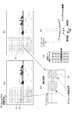
ステップS506で、制御部101は、動きベクトルの検出領域の再設定を行う。図8は、本実施形態における動きベクトルの検出領域の再設定を説明するための図である。図8の画像811と画像812の間、画像821と画像822の間、および、画像831と画像832の間で、動きベクトルを検出するものとする。図8の左側の画像811乃至831には、ステップS501で設定した検出領域が設定され、右側の画像812乃至832には、ステップS506で検出領域が再設定された様子を示す。画像812乃至832のそれぞれに示した再設定された検出領域は、制御部101が画像811乃至831に示した検出領域を絞り込んで狭めたものである。具体的に、制御部101がテンプレートにあたる領域のサイズを変えずに、それらの間隔を縮める。また、制御部101は、小領域のサイズと、小領域とテンプレートとの相対位置関係とを変えずに、小領域を設定する。この再設定された検出領域は、ステップS503で動きベクトルの検出に成功したと判断された小領域の位置に重畳している必要がある。そのため、ステップS503で動きベクトルの検出に成功したと判断された小領域の位置を基準として、再設定する検出領域の位置を調整するようにしてもよい。もし、ステップS503で動きベクトルの検出に成功したと判断された小領域が離れて分布しているならば、その離れた位置のそれぞれを基準として、複数の検出領域を再設定しても良い。 In step S506, the
ステップS507で、制御部101は、ステップS506で再設定した動きベクトルの検出領域から動きベクトルの検出を行う。検出方法は、ステップS502と同様である。 In step S507, the
ステップS508で、制御部101は、ステップS508で検出した動きベクトルが、ステップS502で検出した動きベクトルと同様であるかどうかについて判断する。ステップS508で検出した動きベクトルとステップS502で検出した動きベクトルの大きさと方向の差が所定範囲内である場合に、同様であると判断する。検出した動きベクトルが同様であると判断した場合、ステップS509に進み、動きベクトルの評価のフラグを「高」に設定し、同様でないと判断した場合、ステップS510に進み、動きベクトルの評価のフラグを「低」に設定する。 In step S508, the
なお、制御部101が動きベクトルの検出に成功した領域が移動方向に沿って画像の一部にのみ分布するケースとしては、大きく3種類がある。1つ目は前述した図7に示したような、デジタルカメラの移動方向に対して図案の変化が少ない場合である。2つ目は、図9に示すように、移動方向に沿って分布した小領域の一部に特徴的な図案も含まれているような場合である。図9(a)には、山の前に橋が渡っている画像を示し、図9(b)は制御部101が検出領域を設定する様子を示している。制御部101が検出領域901を設定した場合では、テンプレートとなる領域において図案の変化が少なく、図7と同様に、動きベクトルを検出できても、正確性が低い。この場合、制御部101が検出領域を再設定したとしても、ステップS508で異なる動きベクトルであると判断する可能性が高い。一方で、制御部101が検出領域902を設定した場合では、テンプレートとなる領域が特徴的なる図案である橋脚に被っているため、検出領域901と比べて、検出した動きベクトルの正確性が高い。この場合、制御部101が検出領域を再設定すると、ステップS508で同様な動きベクトルであると判断される可能性が高い。3つ目は、図10に示すように、移動方向に沿って分布した小領域のすべてに特徴的な図案が含まれているような場合である。図10(a)には、海岸沿いに異なる形状の建物が並んでいる画像を示し、図10(b)は制御部101が検出領域を設定する様子を示している。制御部は、検出領域1001と1002のどちらを設定しても、あるいは移動方向に沿った他の場所で検出領域を設定しても、斜線部分と被っている小領域では、正確性の高い動きベクトルを検出できる。図10(a)に示した画像において、制御部101はどこに検出領域を設定しても、検出した動きベクトルと検出領域を再設定して検出した動きベクトルとが同様と判断される可能性が高い。 There are roughly three types of cases in which the area in which the
次に、ステップS304での画像の合成について説明する。 Next, composition of images in step S304 will be described.
図11は、本実施形態における画像の合成を説明するためのフローチャートである。ステップS1101で、制御部101は、ステップS302で撮像した画像から検出した動きベクトルの評価のフラグが「高」であるかどうかについて判断する。動きベクトルの評価のフラグが「高」であれば、ステップS1102に進み、この画像を合成に用いて、検出した動きベクトルで位置合わせを行って、合成を行う。位置合わせの方法としては、公知の射影変換、アフィン変換係数や水平垂直シフトのみの簡略化した位置合わせを用いてよい。一方で、動きベクトルの評価のフラグが「高」でなければ、この画像を合成に用いない。かくして、動きベクトルの評価のフラグが「低」の画像を、パノラマ画像の合成から排除し、代わりに、欠けた画角を、動きベクトルの評価のフラグが「高」の画像を使って補う。 FIG. 11 is a flowchart for explaining composition of images in the present embodiment. In step S1101, the
第1の実施形態によれば、動きベクトルの正確性を判断し、パノラマ画像の合成に用いる画像を選択し、より精度の高い位置合わせを行うことができる。 According to the first embodiment, it is possible to determine the accuracy of the motion vector, select an image to be used for combining panoramic images, and perform more accurate alignment.
(第2の実施形態)
第2の実施形態では、第1の実施形態と異なり、画像の歪などを考慮し、なるべく画像の中央から切り出した領域をパノラマ画像の合成に使うようにする。第1の実施形態の場合では、動きベクトルの評価のフラグが「低」の画像を、パノラマ画像の合成から除外する。除外した画像に相当する画角は、他の画像から補う。しかしながら、前述したように、画像の歪などを考慮し、一般的に画像の中央から切り出した領域を合成に用いる方が好ましい。他の画像から切り出した領域を代替的に用いると、中央から離れた領域しか使えなく、画像の歪による影響で合成したパノラマ画像に違和感が出る可能性がある。また、動きベクトルの評価のフラグが「低」の画像が連続的に撮像すると、合成に使える画像領域が途中で切れてしまう可能性もあり、パノラマ画像の一部の画角が欠けることになる。以上の課題を解決するために、本実施形態では、動きベクトルの評価のフラグを「高」「中」「低」と分け、動きベクトルの評価のフラグが「高」の検出領域を用いるとともに、動きベクトルの評価のフラグが「中」の検出領域の一部を合成に用いる。以下では、本実施形態について詳細に説明する。なお、第1の実施形態と同様な所は省略する。Second Embodiment
In the second embodiment, unlike the first embodiment, an area cut out from the center of the image is used for composition of a panoramic image as much as possible in consideration of distortion of the image and the like. In the case of the first embodiment, an image whose motion vector evaluation flag is “low” is excluded from the panoramic image synthesis. The angle of view corresponding to the excluded image is compensated from other images. However, as described above, it is generally preferable to use a region cut out from the center of the image for synthesis in consideration of image distortion and the like. If a region cut out from another image is used alternatively, only the region far from the center can be used, and there is a possibility that the panoramic image synthesized may be uncomfortable due to the influence of the distortion of the image. In addition, if an image with a motion vector evaluation flag of "low" is continuously captured, there is a possibility that the image area usable for combining may be cut halfway, and a part of the angle of view of the panoramic image may be lost. . In order to solve the above problems, in the present embodiment, the flag of the motion vector evaluation is divided into "high", "middle" and "low", and the detection flag of the motion vector evaluation uses "high". A part of the detection area where the motion vector evaluation flag is "medium" is used for synthesis. Hereinafter, the present embodiment will be described in detail. The same parts as those in the first embodiment are omitted.
本実施形態のフローチャートは第1の実施形態の図2と同様であるが、ステップS303での動きベクトルの評価とステップS304での画像の合成が第1の実施形態と異なる。 The flowchart of this embodiment is the same as that of FIG. 2 of the first embodiment, but the evaluation of the motion vector in step S303 and the composition of the image in step S304 are different from those of the first embodiment.
図12は、本実施形態における動きベクトルの評価を説明するためのフローチャートである。図12に示したフローチャートは、以下のところで第1の実施形態の図5に示したフローチャートと異なる。動きベクトルの評価のフラグの種類に「中」を加え、特定の場合に制御部101がステップS1202で検出した動きベクトルの評価のフラグを「中」に設定する。この特定の場合には、ステップS1204で繰り返しパターンが存在しないとき、ステップS1205で、検出した動きベクトルの分布が均一でないとき、およびステップS1208で検出した動きベクトルが同様でないときが含まれる。 FIG. 12 is a flowchart for explaining the evaluation of motion vectors in the present embodiment. The flowchart shown in FIG. 12 is different from the flowchart shown in FIG. 5 of the first embodiment in the following place. “Mid” is added to the type of the motion vector evaluation flag, and in a specific case, the
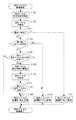
図13は、本実施形態における画像の合成を説明するためのフローチャートである。図13に示したフローチャートでは、仮合成という処理があることで、第1の実施形態の図11に示したフローチャートと異なる。 FIG. 13 is a flowchart for explaining composition of images in the present embodiment. The flowchart shown in FIG. 13 differs from the flowchart shown in FIG. 11 of the first embodiment in that there is a process of temporary combining.
前述したように、第1の実施形態では、動きベクトルの評価のフラグが「低」の画像をすべて画像の合成から除外することで、パノラマ画像に違和感が出る可能性がある。それを解決するために、本実施形態では、動きベクトルの評価のフラグに「中」を設け、動きベクトルの評価のフラグが「中」の画像に対しては仮合成を行う。制御部101は、仮合成の処理で仮合成画像を生成し、仮合成画像は、最終的なパノラマ画像の生成の予備用のためのものであり、動きベクトルの評価のフラグが「高」である画像が存在しない画角に用いられる。 As described above, in the first embodiment, the panoramic image may have a sense of discomfort by excluding all the images whose motion vector evaluation flag is “low” from the image combination. In order to solve the problem, in the present embodiment, "middle" is provided in the flag of motion vector evaluation, and provisional synthesis is performed on an image in which the flag of motion vector evaluation is "middle". The
ステップS1301で、ステップS1202で制御部101が検出した動きベクトルの評価のフラグが「高」であるかどうかについて判断する。動きベクトルの評価のフラグが「高」であれば、ステップS1302に進み、動きベクトルの評価のフラグが「高」でなければ、ステップS1305に進む。ステップS1305で、制御部101が検出した動きベクトルの評価のフラグが「低」であるかどうかについて判断する。動きベクトルの評価のフラグが「低」であれば、その画像についての合成処理のフローが終了し、動きベクトルの評価のフラグが「低」でなければ、ステップS1306に進む。つまり、ステップS1301とステップS1305との処理で、動きベクトルの評価のフラグが「低」ならフローが終了、「中」ならステップS1306に進み、「高」ならステップS1302に進む。 In step S1301, it is determined whether the flag of the motion vector evaluation detected by the
ステップS1302で、第1の実施形態のステップS1102と同様に、制御部101が位置合わせおよび画像の合成を行う。次に、ステップS1303に進む、ステップS1302の合成に用いる領域の画角を有する仮合成画像が存在するかどうかについて判断する。ここでいう仮合成画像とは、後述するステップS1308またはステップS1309で制御部101が生成したものである。本実施形態では、動きベクトルの評価のフラグが「高」の領域を優先的に合成に用いるため、同じ画角を有する仮合成画像は使えなくなるので、ステップS1304で制御部101に消去される。一方、こうした仮合成画像が存在していなければ、フローを終了する。 In step S1302, the
ステップS1306で、制御部101は、ステップS1305で動きベクトルの評価のフラグが「中」と判断した領域の画角と同じ画角を持つ仮合成画像が存在するかどうかについて判断する。こうした仮合成画像がすでに存在する場合、ステップS1307に進み、既存の仮合成画像と仮合成を行おうとする画像との動きベクトルの精度の比較を行う。詳細は後述する。もしステップS1306で仮合成画像が存在していないと判断した場合、ステップS1309に進み、仮合成を行う。図13に明記されていないが、仮合成の前に、ステップS1302での合成と同様に位置合わせなどの前処理が必要である。既存の仮合成画像の精度がよければ、その画像についての合成のフローを終了し、既存の仮合成画像の方の精度がよくなければ、ステップS1308に進み、制御部101は、新たな仮合成画像を生成する。 In step S1306, the
次に、ステップS1307での精度の比較について説明する。制御部101は、既存の仮合成画像と仮合成を行おうとする画像とのそれぞれに対して、検索領域に検出した動きベクトルと、検索領域を再設定して検出した動きベクトルとを比較する。2組の動きベクトルの中で、同じ大きさと方向のものが多いほど、精度が高いとする。検索領域の再設定の方法は、ステップS1206での再設定の方法と同じでよく、先に設定した検索領域を絞り込んで検索領域を再設定する。 Next, the comparison of the accuracy in step S1307 will be described. The
第2の実施形態によれば、仮合成を行い、仮合成画像の中で精度高いものを合成に用いることによって、合成画像の歪や画角の欠陥などを避けることができる。 According to the second embodiment, it is possible to avoid distortion of the composite image, a defect in the angle of view, and the like by performing temporary combining and using a highly accurate temporary combining image for combining.
(その他の実施形態)
なお、上記実施形態においては、個人向けのデジタルカメラをもとに説明を行ったが、パノラマ撮像および合成機能を搭載していれば、携帯機器やスマートフォン、あるいは、サーバーに接続されたネットワークカメラなどに適用することも可能である。(Other embodiments)
Although the above embodiment has been described based on a digital camera for individuals, if a panoramic imaging and combining function is installed, a portable device, a smartphone, a network camera connected to a server, etc. It is also possible to apply to
なお、本発明は、上述の実施形態の1つ以上の機能を実現するプログラムを、ネットワークまたは記憶媒体を介してシステムまたは装置に供給し、そのシステムまたは装置のコンピュータにおける1つ以上のプロセッサーがプログラムを読み出し作動させる処理でも実現可能である。また、1以上の機能を実現する回路(例えば、ASIC)によっても実現可能である。 The present invention supplies a program that implements one or more functions of the above-described embodiments to a system or apparatus via a network or a storage medium, and one or more processors in a computer of the system or apparatus execute the program. Can be realized by processing for reading out and operating. It can also be implemented by a circuit (eg, an ASIC) that implements one or more functions.
100 デジタルカメラ
101 制御部
102 駆動部
103 光学系
104 撮像部
105 ROM
106 RAM
107 画像処理部
108 表示部
109 内蔵メモリ
110 操作部
111 装置動き検出部100
106 RAM
107
Claims (12)
Translated fromJapanese前記複数の画像の少なくとも一部を用いて合成を行い、パノラマ画像を生成する合成手段と、を有し、
前記検出手段は、処理対象の画像の第1の領域、および、前記第1の領域よりも狭い第2の領域から動きベクトルを検出し、
前記合成手段は、前記第1の領域から検出した動きベクトルと前記第2の領域から検出した動きベクトルとの差が所定範囲内であれば、前記処理対象の画像を前記合成に用いることを特徴とする画像処理装置。Detection means for detecting a motion vector from a plurality of images;
Combining at least a part of the plurality of images to generate a panoramic image;
The detection means detects a motion vector from a first area of an image to be processed and a second area narrower than the first area;
The combining means is characterized by using the image to be processed for the combining if the difference between the motion vector detected from the first area and the motion vector detected from the second area is within a predetermined range. Image processing device.
前記複数の画像から動きベクトルを検出する検出手段と、
前記複数の画像の少なくとも一部を用いて合成を行い、パノラマ画像を生成する合成手段と、を有し、
前記検出手段は、処理対象の画像の第1の領域、および、前記第1の領域よりも狭い第2の領域から動きベクトルを検出し、
前記合成手段は、前記第1の領域から検出した動きベクトルと前記第2の領域から検出した動きベクトルとの差が所定範囲内であれば、前記処理対象の画像を前記合成に用いることを特徴とする撮像装置。Imaging means for capturing a plurality of images; detection means for detecting a motion vector from the plurality of images;
Combining at least a part of the plurality of images to generate a panoramic image;
The detection means detects a motion vector from a first area of an image to be processed and a second area narrower than the first area;
The combining means is characterized by using the image to be processed for the combining if the difference between the motion vector detected from the first area and the motion vector detected from the second area is within a predetermined range. An imaging device.
前記複数の画像の少なくとも一部を用いて合成を行い、パノラマ画像を生成する合成ステップと、を有し、
前記検出ステップにおいては、処理対象の画像の第1の領域、および、前記第1の領域よりも狭い第2の領域から動きベクトルを検出し、
前記合成ステップにおいては、前記第1の領域から検出した動きベクトルと前記第2の領域から検出した動きベクトルとの差が所定範囲内であれば、前記処理対象の画像を前記合成に用いることを特徴とする画像処理装置の制御方法。Detecting a motion vector from a plurality of images;
Combining at least a part of the plurality of images to generate a panoramic image;
In the detection step, a motion vector is detected from a first region of an image to be processed and a second region narrower than the first region;
In the combining step, if the difference between the motion vector detected from the first region and the motion vector detected from the second region is within a predetermined range, the image to be processed is used for the combining. The control method of the image processing apparatus characterized by the above.
複数の画像から動きベクトルを検出する検出ステップと、
前記複数の画像の少なくとも一部を用いて合成を行い、パノラマ画像を生成する合成ステップと、を行わせ、
前記検出ステップにおいては、処理対象の画像の第1の領域、および、前記第1の領域よりも狭い第2の領域から動きベクトルを検出し、
前記合成ステップにおいては、前記第1の領域から検出した動きベクトルと前記第2の領域から検出した動きベクトルとの差が所定範囲内であれば、前記処理対象の画像を前記合成に用いることを特徴とするプログラム。A computer program that causes a computer of an image processing apparatus to operate,
Detecting a motion vector from a plurality of images;
Combining using at least a part of the plurality of images to generate a panoramic image;
In the detection step, a motion vector is detected from a first region of an image to be processed and a second region narrower than the first region;
In the combining step, if the difference between the motion vector detected from the first region and the motion vector detected from the second region is within a predetermined range, the image to be processed is used for the combining. Program to feature.
Priority Applications (2)
| Application Number | Priority Date | Filing Date | Title |
|---|---|---|---|
| JP2017160568AJP6545229B2 (en) | 2017-08-23 | 2017-08-23 | IMAGE PROCESSING APPARATUS, IMAGING APPARATUS, CONTROL METHOD OF IMAGE PROCESSING APPARATUS, AND PROGRAM |
| US16/107,665US10805609B2 (en) | 2017-08-23 | 2018-08-21 | Image processing apparatus to generate panoramic image, image pickup apparatus to generate panoramic image, control method of image processing apparatus to generate panoramic image, and non-transitory computer readable storage medium to generate panoramic image |
Applications Claiming Priority (1)
| Application Number | Priority Date | Filing Date | Title |
|---|---|---|---|
| JP2017160568AJP6545229B2 (en) | 2017-08-23 | 2017-08-23 | IMAGE PROCESSING APPARATUS, IMAGING APPARATUS, CONTROL METHOD OF IMAGE PROCESSING APPARATUS, AND PROGRAM |
Publications (2)
| Publication Number | Publication Date |
|---|---|
| JP2019041188A JP2019041188A (en) | 2019-03-14 |
| JP6545229B2true JP6545229B2 (en) | 2019-07-17 |
Family
ID=65435775
Family Applications (1)
| Application Number | Title | Priority Date | Filing Date |
|---|---|---|---|
| JP2017160568AExpired - Fee RelatedJP6545229B2 (en) | 2017-08-23 | 2017-08-23 | IMAGE PROCESSING APPARATUS, IMAGING APPARATUS, CONTROL METHOD OF IMAGE PROCESSING APPARATUS, AND PROGRAM |
Country Status (2)
| Country | Link |
|---|---|
| US (1) | US10805609B2 (en) |
| JP (1) | JP6545229B2 (en) |
Families Citing this family (2)
| Publication number | Priority date | Publication date | Assignee | Title |
|---|---|---|---|---|
| CN108989606B (en)* | 2018-08-22 | 2021-02-09 | Oppo广东移动通信有限公司 | Image processing method and apparatus, electronic device, computer-readable storage medium |
| JP7628433B2 (en) | 2021-01-27 | 2025-02-10 | アポロ精工株式会社 | IMAGE SYNTHESIS DEVICE, IMAGE SYNTHESIS METHOD, AND PROGRAM |
Family Cites Families (75)
| Publication number | Priority date | Publication date | Assignee | Title |
|---|---|---|---|---|
| US5712474A (en)* | 1993-09-29 | 1998-01-27 | Canon Kabushiki Kaisha | Image processing apparatus for correcting blurring of an image photographed by a video camera |
| US6285711B1 (en)* | 1998-05-20 | 2001-09-04 | Sharp Laboratories Of America, Inc. | Block matching-based method for estimating motion fields and global affine motion parameters in digital video sequences |
| JP2001197501A (en)* | 2000-01-07 | 2001-07-19 | Fujitsu Ltd | Motion vector searcher, motion vector search method, and video encoding device |
| AU2002305387B2 (en)* | 2001-05-04 | 2008-04-03 | Legend Films, Llc | Image sequence enhancement system and method |
| KR20030059399A (en)* | 2001-12-29 | 2003-07-10 | 엘지전자 주식회사 | Video browsing systme based on mosaic image |
| CN1656515A (en)* | 2002-05-30 | 2005-08-17 | 皇家飞利浦电子股份有限公司 | Unit for and method of estimating a current motion vector |
| EP1376471A1 (en)* | 2002-06-19 | 2004-01-02 | STMicroelectronics S.r.l. | Motion estimation for stabilization of an image sequence |
| JP3962676B2 (en)* | 2002-11-29 | 2007-08-22 | キヤノン株式会社 | Image processing method and apparatus |
| US8411902B2 (en)* | 2004-04-07 | 2013-04-02 | Hewlett-Packard Development Company, L.P. | Providing a visual indication of the content of a video by analyzing a likely user intent |
| US7623682B2 (en)* | 2004-08-13 | 2009-11-24 | Samsung Electronics Co., Ltd. | Method and device for motion estimation and compensation for panorama image |
| CN100455266C (en)* | 2005-03-29 | 2009-01-28 | 深圳迈瑞生物医疗电子股份有限公司 | Wide-field imaging processing method |
| JP4595733B2 (en)* | 2005-08-02 | 2010-12-08 | カシオ計算機株式会社 | Image processing device |
| JP2009505476A (en)* | 2005-08-10 | 2009-02-05 | エヌエックスピー ビー ヴィ | Method and apparatus for digital image stabilization |
| EP2013849A1 (en)* | 2006-04-24 | 2009-01-14 | Nxp B.V. | Method and device for generating a panoramic image from a video sequence |
| KR100725053B1 (en)* | 2006-06-22 | 2007-06-08 | 삼성전자주식회사 | Panoramic photographing device and method of portable terminal |
| CN101479767A (en)* | 2006-06-30 | 2009-07-08 | Nxp股份有限公司 | A method and device for video stitching |
| EP2063390B1 (en)* | 2006-09-14 | 2016-08-03 | Fujitsu Limited | Image processing device and its program |
| US7809212B2 (en)* | 2006-12-20 | 2010-10-05 | Hantro Products Oy | Digital mosaic image construction |
| KR100800804B1 (en)* | 2006-12-27 | 2008-02-04 | 삼성전자주식회사 | Panorama shooting method |
| US8149911B1 (en)* | 2007-02-16 | 2012-04-03 | Maxim Integrated Products, Inc. | Method and/or apparatus for multiple pass digital image stabilization |
| KR101312895B1 (en)* | 2007-08-27 | 2013-09-30 | 재단법인서울대학교산학협력재단 | Method for photographing panorama picture |
| WO2009039512A1 (en)* | 2007-09-21 | 2009-03-26 | The Trustees Of Columbia University In The City Of New York | Systems and methods for panoramic imaging |
| KR101409653B1 (en)* | 2007-12-18 | 2014-06-19 | 삼성전자주식회사 | Method for photographing panorama picture in automation |
| TWI381719B (en)* | 2008-02-18 | 2013-01-01 | Univ Nat Taiwan | Full-frame video stabilization with a polyline-fitted camcorder path |
| KR100919247B1 (en)* | 2008-03-12 | 2009-09-30 | 중앙대학교 산학협력단 | Apparatus and method for panorama image generation and apparatus and method for object tracking using the same |
| JP2009278432A (en)* | 2008-05-15 | 2009-11-26 | Olympus Imaging Corp | Imaging apparatus, and imaging method in imaging apparatus |
| JP5338174B2 (en)* | 2008-07-28 | 2013-11-13 | 富士通株式会社 | Panorama photographing apparatus and method, camera unit equipped with panoramic photographing apparatus |
| KR101299249B1 (en)* | 2008-08-29 | 2013-08-22 | 삼성테크윈 주식회사 | Digital photographing apparatus, method for controlling the same, and recording medium storing program to implement the method |
| JP2010081411A (en)* | 2008-09-26 | 2010-04-08 | Toshiba Corp | Frame interpolation device and frame interpolation method |
| JP5163409B2 (en)* | 2008-10-03 | 2013-03-13 | ソニー株式会社 | Imaging apparatus, imaging method, and program |
| JP2010136302A (en)* | 2008-12-08 | 2010-06-17 | Sony Corp | Imaging apparatus, imaging method and program |
| TWI490819B (en)* | 2009-01-09 | 2015-07-01 | Mstar Semiconductor Inc | Image processing method and apparatus thereof |
| TW201030631A (en)* | 2009-02-04 | 2010-08-16 | Altek Corp | Automatic photographing method for panoramic image of digital imaging apparatus |
| JP5187266B2 (en)* | 2009-04-21 | 2013-04-24 | 株式会社Jvcケンウッド | Motion vector detection apparatus and method |
| IT1395648B1 (en)* | 2009-05-28 | 2012-10-16 | St Microelectronics Srl | PROCEDURE AND SYSTEM FOR DETECTION OF PORNOGRAPHIC CONTENT IN VIDEO SEQUENCES, RELATIVE COMPUTER PRODUCT |
| US8947502B2 (en)* | 2011-04-06 | 2015-02-03 | Qualcomm Technologies, Inc. | In camera implementation of selecting and stitching frames for panoramic imagery |
| JP5359783B2 (en)* | 2009-10-28 | 2013-12-04 | ソニー株式会社 | Image processing apparatus and method, and program |
| KR101661969B1 (en)* | 2009-11-02 | 2016-10-04 | 엘지전자 주식회사 | Mobile terminal and operation control method thereof |
| JP2011130327A (en)* | 2009-12-21 | 2011-06-30 | Sony Corp | Image processing apparatus, method and program |
| JP2011166264A (en)* | 2010-02-05 | 2011-08-25 | Sony Corp | Image processing apparatus, imaging device and image processing method, and program |
| JP5380336B2 (en) | 2010-03-04 | 2014-01-08 | 富士フイルム株式会社 | Imaging apparatus, panoramic image synthesis method and program thereof |
| US8285079B2 (en)* | 2010-03-19 | 2012-10-09 | Sony Corporation | Method for highly accurate estimation of motion using phase correlation |
| US20110234750A1 (en)* | 2010-03-24 | 2011-09-29 | Jimmy Kwok Lap Lai | Capturing Two or More Images to Form a Panoramic Image |
| KR101663321B1 (en)* | 2010-07-30 | 2016-10-17 | 삼성전자주식회사 | Method for photographing panorama picture |
| US8792559B2 (en)* | 2010-10-26 | 2014-07-29 | Sony Corporation | Method to improve accuracy and reliability of motion estimated with phase correlation |
| US8675080B2 (en)* | 2010-12-30 | 2014-03-18 | Stmicroelectronics, Inc. | Motion estimation in imaging systems |
| JP5770486B2 (en)* | 2011-02-21 | 2015-08-26 | 株式会社トプコン | All-around image measuring device |
| JP2012191486A (en)* | 2011-03-11 | 2012-10-04 | Sony Corp | Image composing apparatus, image composing method, and program |
| JP2012227669A (en)* | 2011-04-19 | 2012-11-15 | Sony Corp | Information processing apparatus, information processing method and program |
| JP2013020527A (en)* | 2011-07-13 | 2013-01-31 | Sony Corp | Image processing device, method, and program |
| JP2013020528A (en)* | 2011-07-13 | 2013-01-31 | Sony Corp | Image processing device, method, and program |
| JP2013041387A (en)* | 2011-08-15 | 2013-02-28 | Sony Corp | Image processing device, image processing method, imaging device, electronic device, and program |
| JP5729237B2 (en)* | 2011-09-26 | 2015-06-03 | カシオ計算機株式会社 | Image processing apparatus, image processing method, and program |
| JP6222514B2 (en)* | 2012-01-11 | 2017-11-01 | パナソニックIpマネジメント株式会社 | Image processing apparatus, imaging apparatus, and computer program |
| JP6037224B2 (en)* | 2012-01-11 | 2016-12-07 | パナソニックIpマネジメント株式会社 | Image processing apparatus, imaging apparatus, and program |
| JP6151355B2 (en)* | 2012-05-18 | 2017-06-21 | トムソン ライセンシングThomson Licensing | Panorama picture processing |
| JP6025467B2 (en)* | 2012-09-12 | 2016-11-16 | キヤノン株式会社 | Image processing apparatus and image processing method |
| US8937702B2 (en)* | 2012-10-30 | 2015-01-20 | Eastman Kodak Company | Method of making a panoramic print |
| US9105108B2 (en)* | 2012-10-30 | 2015-08-11 | Eastman Kodak Company | System for making a panoramic print |
| IES20120509A2 (en)* | 2012-11-27 | 2014-06-04 | Digitaloptics Corp Europe Ltd | Digital image capture device having a panorama mode |
| US9398215B2 (en)* | 2013-04-16 | 2016-07-19 | Eth Zurich | Stereoscopic panoramas |
| US9247129B1 (en)* | 2013-08-30 | 2016-01-26 | A9.Com, Inc. | Self-portrait enhancement techniques |
| US9300882B2 (en)* | 2014-02-27 | 2016-03-29 | Sony Corporation | Device and method for panoramic image processing |
| JP2015186015A (en)* | 2014-03-24 | 2015-10-22 | 株式会社Jvcケンウッド | image processing apparatus, image processing method, program and camera |
| JP6197749B2 (en)* | 2014-03-31 | 2017-09-20 | 株式会社Jvcケンウッド | Image processing apparatus, image processing method, program, and camera |
| US9813620B2 (en)* | 2014-03-31 | 2017-11-07 | JVC Kenwood Corporation | Image processing apparatus, image processing method, program, and camera |
| JP6197771B2 (en)* | 2014-09-25 | 2017-09-20 | 株式会社Jvcケンウッド | Image joining apparatus, imaging apparatus, image joining method, and image joining program |
| AU2015202937A1 (en)* | 2015-05-29 | 2016-12-15 | Canon Kabushiki Kaisha | Systems and methods for registration of images |
| JP6769440B2 (en)* | 2015-09-18 | 2020-10-14 | ソニー株式会社 | Image processing equipment, image processing methods, programs and imaging systems |
| US20170118475A1 (en)* | 2015-10-22 | 2017-04-27 | Mediatek Inc. | Method and Apparatus of Video Compression for Non-stitched Panoramic Contents |
| JP6659130B2 (en)* | 2015-12-04 | 2020-03-04 | キヤノン株式会社 | Image processing apparatus, imaging apparatus, image processing method, and program |
| WO2017115348A1 (en)* | 2016-01-03 | 2017-07-06 | Humaneyes Technologies Ltd. | Adaptive stitching of frames in the process of creating a panoramic frame |
| US10148875B1 (en)* | 2016-05-17 | 2018-12-04 | Scott Zhihao Chen | Method and system for interfacing multiple channels of panoramic videos with a high-definition port of a processor |
| JP2017212698A (en)* | 2016-05-27 | 2017-11-30 | キヤノン株式会社 | IMAGING DEVICE, IMAGING DEVICE CONTROL METHOD, AND PROGRAM |
| US10284875B2 (en)* | 2016-08-08 | 2019-05-07 | Qualcomm Incorporated | Systems and methods for determining feature point motion |
- 2017
- 2017-08-23JPJP2017160568Apatent/JP6545229B2/ennot_activeExpired - Fee Related
- 2018
- 2018-08-21USUS16/107,665patent/US10805609B2/ennot_activeExpired - Fee Related
Also Published As
| Publication number | Publication date |
|---|---|
| JP2019041188A (en) | 2019-03-14 |
| US20190068972A1 (en) | 2019-02-28 |
| US10805609B2 (en) | 2020-10-13 |
Similar Documents
| Publication | Publication Date | Title |
|---|---|---|
| JP5206095B2 (en) | Composition determination apparatus, composition determination method, and program | |
| US20150070526A1 (en) | Display control device, display control method, and program | |
| JP6700831B2 (en) | Image processing device, imaging device, image processing method, and program | |
| CN107040713B (en) | Motion vector detection apparatus, control method therefor, and image pickup apparatus | |
| CN103888684B (en) | Image processing apparatus, image processing method and recording medium | |
| JP6604908B2 (en) | Image processing apparatus, control method thereof, and control program | |
| US20170111574A1 (en) | Imaging apparatus and imaging method | |
| CN103312975A (en) | Image processing apparatus that combines images | |
| JP7158841B2 (en) | Imaging device, imaging method, program, recording medium, and image processing device | |
| JP2013183306A (en) | Imaging apparatus, imaging method, and program | |
| JP6786311B2 (en) | Image processing equipment, image processing methods, computer programs and storage media | |
| JP2019125928A (en) | Imaging device, imaging method, and program | |
| JP6545229B2 (en) | IMAGE PROCESSING APPARATUS, IMAGING APPARATUS, CONTROL METHOD OF IMAGE PROCESSING APPARATUS, AND PROGRAM | |
| JP2017143354A (en) | Image processing apparatus and image processing method | |
| JP6961423B2 (en) | Image processing equipment, imaging equipment, control methods for image processing equipment, programs and recording media | |
| JP6647246B2 (en) | Image processing apparatus, imaging apparatus, control method for image processing apparatus, and program | |
| JP2009258005A (en) | Three-dimensional measuring device and three-dimensional measuring method | |
| JP6590894B2 (en) | Image processing apparatus, imaging apparatus, image processing method, and program | |
| JP7458769B2 (en) | Image processing device, imaging device, image processing method, program and recording medium | |
| JP6700706B2 (en) | Information processing apparatus, information processing method, and program | |
| KR101603876B1 (en) | Method for fabricating a panorama | |
| JP7608119B2 (en) | Image processing device, image processing method, imaging device, program, and recording medium | |
| JP7409604B2 (en) | Image processing device, imaging device, image processing method, program and recording medium | |
| JP6828069B2 (en) | Imaging equipment, imaging methods and programs | |
| JP6604998B2 (en) | Image processing apparatus, imaging apparatus, image processing apparatus control method, and program |
Legal Events
| Date | Code | Title | Description |
|---|---|---|---|
| TRDD | Decision of grant or rejection written | ||
| A01 | Written decision to grant a patent or to grant a registration (utility model) | Free format text:JAPANESE INTERMEDIATE CODE: A01 Effective date:20190521 | |
| A61 | First payment of annual fees (during grant procedure) | Free format text:JAPANESE INTERMEDIATE CODE: A61 Effective date:20190618 | |
| R151 | Written notification of patent or utility model registration | Ref document number:6545229 Country of ref document:JP Free format text:JAPANESE INTERMEDIATE CODE: R151 | |
| LAPS | Cancellation because of no payment of annual fees |