JP6544290B2 - Temperature detection apparatus, image forming apparatus, temperature detection method - Google Patents
Temperature detection apparatus, image forming apparatus, temperature detection methodDownload PDFInfo
- Publication number
- JP6544290B2 JP6544290B2JP2016091140AJP2016091140AJP6544290B2JP 6544290 B2JP6544290 B2JP 6544290B2JP 2016091140 AJP2016091140 AJP 2016091140AJP 2016091140 AJP2016091140 AJP 2016091140AJP 6544290 B2JP6544290 B2JP 6544290B2
- Authority
- JP
- Japan
- Prior art keywords
- signal value
- temperature
- equation
- constant
- processing unit
- Prior art date
- Legal status (The legal status is an assumption and is not a legal conclusion. Google has not performed a legal analysis and makes no representation as to the accuracy of the status listed.)
- Active
Links
Images


Classifications
- G—PHYSICS
- G01—MEASURING; TESTING
- G01K—MEASURING TEMPERATURE; MEASURING QUANTITY OF HEAT; THERMALLY-SENSITIVE ELEMENTS NOT OTHERWISE PROVIDED FOR
- G01K7/00—Measuring temperature based on the use of electric or magnetic elements directly sensitive to heat ; Power supply therefor, e.g. using thermoelectric elements
- G01K7/02—Measuring temperature based on the use of electric or magnetic elements directly sensitive to heat ; Power supply therefor, e.g. using thermoelectric elements using thermoelectric elements, e.g. thermocouples
- G01K7/021—Particular circuit arrangements
- G—PHYSICS
- G03—PHOTOGRAPHY; CINEMATOGRAPHY; ANALOGOUS TECHNIQUES USING WAVES OTHER THAN OPTICAL WAVES; ELECTROGRAPHY; HOLOGRAPHY
- G03G—ELECTROGRAPHY; ELECTROPHOTOGRAPHY; MAGNETOGRAPHY
- G03G15/00—Apparatus for electrographic processes using a charge pattern
- G03G15/20—Apparatus for electrographic processes using a charge pattern for fixing, e.g. by using heat
- G03G15/2003—Apparatus for electrographic processes using a charge pattern for fixing, e.g. by using heat using heat
- G03G15/2014—Apparatus for electrographic processes using a charge pattern for fixing, e.g. by using heat using heat using contact heat
- G03G15/2039—Apparatus for electrographic processes using a charge pattern for fixing, e.g. by using heat using heat using contact heat with means for controlling the fixing temperature
- G—PHYSICS
- G01—MEASURING; TESTING
- G01K—MEASURING TEMPERATURE; MEASURING QUANTITY OF HEAT; THERMALLY-SENSITIVE ELEMENTS NOT OTHERWISE PROVIDED FOR
- G01K7/00—Measuring temperature based on the use of electric or magnetic elements directly sensitive to heat ; Power supply therefor, e.g. using thermoelectric elements
- G01K7/02—Measuring temperature based on the use of electric or magnetic elements directly sensitive to heat ; Power supply therefor, e.g. using thermoelectric elements using thermoelectric elements, e.g. thermocouples
- G01K7/04—Measuring temperature based on the use of electric or magnetic elements directly sensitive to heat ; Power supply therefor, e.g. using thermoelectric elements using thermoelectric elements, e.g. thermocouples the object to be measured not forming one of the thermoelectric materials
- G—PHYSICS
- G01—MEASURING; TESTING
- G01K—MEASURING TEMPERATURE; MEASURING QUANTITY OF HEAT; THERMALLY-SENSITIVE ELEMENTS NOT OTHERWISE PROVIDED FOR
- G01K7/00—Measuring temperature based on the use of electric or magnetic elements directly sensitive to heat ; Power supply therefor, e.g. using thermoelectric elements
- G01K7/42—Circuits effecting compensation of thermal inertia; Circuits for predicting the stationary value of a temperature
- G—PHYSICS
- G03—PHOTOGRAPHY; CINEMATOGRAPHY; ANALOGOUS TECHNIQUES USING WAVES OTHER THAN OPTICAL WAVES; ELECTROGRAPHY; HOLOGRAPHY
- G03G—ELECTROGRAPHY; ELECTROPHOTOGRAPHY; MAGNETOGRAPHY
- G03G15/00—Apparatus for electrographic processes using a charge pattern
- G03G15/20—Apparatus for electrographic processes using a charge pattern for fixing, e.g. by using heat
- G03G15/2003—Apparatus for electrographic processes using a charge pattern for fixing, e.g. by using heat using heat
- G—PHYSICS
- G01—MEASURING; TESTING
- G01K—MEASURING TEMPERATURE; MEASURING QUANTITY OF HEAT; THERMALLY-SENSITIVE ELEMENTS NOT OTHERWISE PROVIDED FOR
- G01K2207/00—Application of thermometers in household appliances
Landscapes
- Physics & Mathematics (AREA)
- General Physics & Mathematics (AREA)
- Fixing For Electrophotography (AREA)
Description
Translated fromJapanese本発明は、電子写真方式の画像形成装置、画像形成装置に設けられる温度検出装置、及び温度検出方法に関する。 The present invention relates to an electrophotographic image forming apparatus, a temperature detection apparatus provided in the image forming apparatus, and a temperature detection method.
電子写真方式で画像を形成可能なプリンターなどの画像形成装置は、定着装置を備える。定着装置は、トナー像をシートに定着させる定着ローラーなどの定着部材を備える。この種の画像形成装置では、定着部材の温度が検出されて、検出された定着部材の温度に基づいて定着部材を加熱させる熱源の駆動が制御される。ここで、熱電対を用いて定着部材の温度を検出する画像形成装置が知られている(特許文献1参照)。 An image forming apparatus such as a printer capable of forming an image by an electrophotographic method includes a fixing device. The fixing device includes a fixing member such as a fixing roller for fixing a toner image to a sheet. In this type of image forming apparatus, the temperature of the fixing member is detected, and the drive of a heat source that heats the fixing member is controlled based on the detected temperature of the fixing member. Here, an image forming apparatus that detects the temperature of the fixing member using a thermocouple is known (see Patent Document 1).
ところで、定着部材の温度の検出に熱電対が用いられる場合、画像形成装置では、熱電対から出力される信号値と熱電対の冷接点の温度を検出するセンサーから出力される信号値とが代入される変数を含む温度算出用の式を用いた演算処理が実行される。ここで、熱電対から出力される信号値、センサーから出力される信号値、及び温度算出用の式に含まれる定数に小数点以下の位が含まれる場合、演算処理を実行する制御部の処理負荷が大きくなって、制御部で実行される他の処理の実行速度が低下することがある。一方、熱電対から出力される信号値、センサーから出力される信号値、及び温度算出用の式に含まれる定数の各々に10の累乗数が乗算されて、それらの値が予め整数に変換される場合は、演算処理において制御部の処理負荷が大きい除算を行う必要がある。 By the way, when a thermocouple is used to detect the temperature of the fixing member, in the image forming apparatus, the signal value output from the thermocouple and the signal value output from the sensor for detecting the temperature of the cold junction of the thermocouple are substituted. The arithmetic processing using the equation for temperature calculation including the variable is performed. Here, when the signal value output from the thermocouple, the signal value output from the sensor, and the constant included in the equation for temperature calculation include the decimal places, the processing load of the control unit that executes the arithmetic processing May become large, and the execution speed of other processes performed by the control unit may decrease. On the other hand, each of the signal value output from the thermocouple, the signal value output from the sensor, and the constant included in the equation for temperature calculation is multiplied by a power of 10, and those values are converted into integers in advance. In this case, it is necessary to perform division with a large processing load on the control unit in the arithmetic processing.
本発明の目的は、熱電対を用いて定着部材の温度を検出する制御部の処理負荷を軽減可能な温度検出装置、画像形成装置、及び温度検出方法を提供することにある。 An object of the present invention is to provide a temperature detection apparatus, an image forming apparatus, and a temperature detection method capable of reducing the processing load of a control unit that detects the temperature of a fixing member using a thermocouple.
本発明の一の局面に係る温度検出装置は、温接点及び冷接点を有し、前記温接点と前記冷接点との間に生じる熱起電力に応じた第1信号値を出力する熱電対と、前記冷接点の温度を検出して検出温度に応じた第2信号値を出力する検出部と、を備え、前記第1信号値及び前記第2信号値が代入される変数を含む温度算出用の2次以上の高次式を用いてトナー像の定着に用いられる定着部材の温度を検出する。具体的に、前記第1信号値、前記第2信号値、及び前記高次式に含まれる定数のいずれか一つ又は複数には、小数点以下の位が含まれている。また、前記温度検出装置は、変換処理部と、算出処理部とを備える。前記変換処理部は、前記第1信号値、前記第2信号値、及び前記定数の各々に対して2の累乗数を乗算して、乗算結果各々を前記乗算結果各々に近似した整数に変換する。前記算出処理部は、前記高次式において前記定数が前記変換処理部による変換後の前記定数に置換された第1変形式に前記変換処理部による変換後の前記第1信号値及び前記第2信号値を代入すると共に、前記第1変形式に含まれる項各々に対して2の累乗数の乗算又は除算を行うことによって前記定着部材の温度を算出する。 A temperature detection device according to one aspect of the present invention includes a hot junction and a cold junction, and a thermocouple that outputs a first signal value according to a thermoelectromotive force generated between the hot junction and the cold junction. A detection unit that detects the temperature of the cold junction and outputs a second signal value corresponding to the detected temperature; and a temperature calculation that includes variables into which the first signal value and the second signal value are substituted. The temperature of the fixing member used to fix the toner image is detected by using a second or higher order equation of Specifically, one or more of the first signal value, the second signal value, and the constant included in the high-order equation include decimal places. Further, the temperature detection device includes a conversion processing unit and a calculation processing unit. The conversion processing unit multiplies each of the first signal value, the second signal value, and the constant by a power of two, and converts each of the multiplication results into an integer approximated to each of the multiplication results. . The calculation processing unit is configured to convert the first signal value and the second signal converted by the conversion processing unit into a first modified equation in which the constant is replaced by the constant converted by the conversion processing unit in the high-order equation. The temperature of the fixing member is calculated by substituting a signal value and performing multiplication or division of a power of 2 on each of the terms included in the first modification.
本発明の他の局面に係る画像形成装置は、温度検出装置と、定着部材とを備える。前記定着部材は、トナー像の定着に用いられる。前記温度検出装置は、温接点及び冷接点を有し、前記温接点と前記冷接点との間に生じる熱起電力に応じた第1信号値を出力する熱電対と、前記冷接点の温度を検出して検出温度に応じた第2信号値を出力する検出部と、を備え、前記第1信号値及び前記第2信号値が代入される変数を含む温度算出用の2次以上の高次式を用いて前記定着部材の温度を検出する。具体的に、前記第1信号値、前記第2信号値、及び前記高次式に含まれる定数のいずれか一つ又は複数には、小数点以下の位が含まれている。また、前記温度検出装置は、変換処理部と、算出処理部とを備える。前記変換処理部は、前記第1信号値、前記第2信号値、及び前記定数の各々に対して2の累乗数を乗算して、乗算結果各々を前記乗算結果各々に近似した整数に変換する。前記算出処理部は、前記高次式において前記定数が前記変換処理部による変換後の前記定数に置換された第1変形式に前記変換処理部による変換後の前記第1信号値及び前記第2信号値を代入すると共に、前記第1変形式に含まれる項各々に対して2の累乗数の乗算又は除算を行うことによって前記定着部材の温度を算出する。 An image forming apparatus according to another aspect of the present invention includes a temperature detection device and a fixing member. The fixing member is used to fix a toner image. The temperature detection device includes a hot junction and a cold junction, and a thermocouple for outputting a first signal value corresponding to a thermoelectromotive force generated between the hot junction and the cold junction, and a temperature of the cold junction A detection unit for detecting and outputting a second signal value according to a detected temperature, wherein the first signal value and a variable to which the second signal value is substituted, and a second or higher order for temperature calculation including: The temperature of the fixing member is detected using a formula. Specifically, one or more of the first signal value, the second signal value, and the constant included in the high-order equation include decimal places. Further, the temperature detection device includes a conversion processing unit and a calculation processing unit. The conversion processing unit multiplies each of the first signal value, the second signal value, and the constant by a power of two, and converts each of the multiplication results into an integer approximated to each of the multiplication results. . The calculation processing unit is configured to convert the first signal value and the second signal converted by the conversion processing unit into a first modified equation in which the constant is replaced by the constant converted by the conversion processing unit in the high-order equation. The temperature of the fixing member is calculated by substituting a signal value and performing multiplication or division of a power of 2 on each of the terms included in the first modification.
本発明の他の局面に係る温度検出方法は、温接点及び冷接点を有し、前記温接点と前記冷接点との間に生じる熱起電力に応じた第1信号値を出力する熱電対と、前記冷接点の温度を検出して検出温度に応じた第2信号値を出力する検出部と、を備え、前記第1信号値及び前記第2信号値が代入される変数を含む温度算出用の2次以上の高次式を用いてトナー像の定着に用いられる定着部材の温度を検出する温度検出装置で実行される。具体的に、前記第1信号値、前記第2信号値、及び前記高次式に含まれる定数のいずれか一つ又は複数には、小数点以下の位が含まれている。また、前記温度検出方法は、以下の第1ステップ、及び第2ステップを含む。前記第1ステップでは、前記第1信号値、前記第2信号値、及び前記定数の各々に対して2の累乗数が乗算されて、乗算結果各々が前記乗算結果各々に近似した整数に変換される。前記第2ステップでは、前記高次式において前記定数が前記第1ステップによる変換後の前記定数に置換された第1変形式に前記第1ステップによる変換後の前記第1信号値及び前記第2信号値が代入されると共に、前記第1変形式に含まれる項各々に対して2の累乗数の乗算又は除算が行われることによって前記定着部材の温度が算出される。 A temperature detection method according to another aspect of the present invention is a thermocouple having a hot junction and a cold junction, and outputting a first signal value according to a thermoelectromotive force generated between the hot junction and the cold junction. A detection unit that detects the temperature of the cold junction and outputs a second signal value corresponding to the detected temperature; and a temperature calculation that includes variables into which the first signal value and the second signal value are substituted. This is executed by a temperature detection device which detects the temperature of a fixing member used for fixing a toner image by using a second or higher order equation of Specifically, one or more of the first signal value, the second signal value, and the constant included in the high-order equation include decimal places. In addition, the temperature detection method includes the following first step and second step. In the first step, each of the first signal value, the second signal value, and the constant is multiplied by a power of two, and each of the multiplication results is converted into an integer approximated to each of the multiplication results. Ru. In the second step, the first signal value after conversion by the first step and the second signal value are converted into a first modified equation in which the constant is replaced by the constant after conversion by the first step in the high order equation. The temperature of the fixing member is calculated by substituting a signal value and performing multiplication or division of a power of 2 for each of the terms included in the first modification.
本発明によれば、熱電対を用いて定着部材の温度を検出する制御部の処理負荷を軽減することが可能である。 According to the present invention, it is possible to reduce the processing load of the control unit that detects the temperature of the fixing member using a thermocouple.
以下、添付図面を参照しながら、本発明の実施形態について説明する。なお、以下の実施形態は、本発明を具体化した一例であって、本発明の技術的範囲を限定するものではない。 Hereinafter, embodiments of the present invention will be described with reference to the accompanying drawings. The following embodiments are merely specific examples of the present invention, and do not limit the technical scope of the present invention.
[画像形成装置10の概略構成]
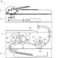
まず、図1及び図2を参照しつつ、本発明の実施形態に係る画像形成装置10の概略構成について説明する。ここで、図1は画像形成装置10の構成を示す断面模式図である。[Schematic Configuration of Image Forming Apparatus 10]
First, a schematic configuration of an
画像形成装置10は、原稿から画像データを読み取るスキャン機能、及び画像データに基づいて画像を形成するプリント機能と共に、ファクシミリ機能、及びコピー機能などの複数の機能を有する複合機である。また、本発明は、プリンター装置、ファクシミリ装置、及びコピー機などの画像形成装置に適用可能である。 The
図1及び図2に示されるように、画像形成装置10は、ADF(自動原稿搬送装置)1、画像読取部2、画像形成部3、給紙部4、制御部5、操作表示部6、及び記憶部7を備える。 As shown in FIGS. 1 and 2, the
制御部5は、不図示のCPU、ROM、RAM、及びEEPROM(登録商標)などの制御機器を備える。前記CPUは、各種の演算処理を実行するプロセッサーである。前記ROMは、前記CPUに各種の処理を実行させるための制御プログラムなどの情報が予め記憶される不揮発性の記憶媒体である。前記RAMは揮発性の記憶媒体であり、前記EEPROMは不揮発性の記憶媒体である。前記RAM及び前記EEPROMは、前記CPUが実行する各種の処理の一時記憶メモリー(作業領域)として使用される。制御部5では、前記CPUにより前記ROMに予め記憶された各種の制御プログラムが実行される。これにより、画像形成装置10が制御部5により統括的に制御される。なお、制御部5は、集積回路(ASIC)などの電子回路で構成されたものであってもよく、画像形成装置10を統括的に制御するメイン制御部とは別に設けられた制御部であってもよい。 The control unit 5 includes control devices such as a CPU, a ROM, a RAM, and an EEPROM (registered trademark) (not shown). The CPU is a processor that executes various arithmetic processing. The ROM is a non-volatile storage medium in which information such as a control program for causing the CPU to execute various processes is stored in advance. The RAM is a volatile storage medium, and the EEPROM is a non-volatile storage medium. The RAM and the EEPROM are used as temporary storage memories (work areas) of various processes executed by the CPU. In the control unit 5, the CPU executes various control programs stored in advance in the ROM. As a result, the
記憶部7は、不揮発性の記憶媒体である。例えば、記憶部7は、フラッシュメモリー、SSD(ソリッドステートドライブ)、又はHDD(ハードディスクドライブ)などの記憶媒体である。 The storage unit 7 is a non-volatile storage medium. For example, the storage unit 7 is a storage medium such as a flash memory, an SSD (solid state drive), or an HDD (hard disk drive).
画像形成部3は、画像読取部2で読み取られた画像データ又は外部のパーソナルコンピューター等の情報処理装置から入力された画像データに基づいて、電子写真方式で画像を形成可能である。具体的に、画像形成部3は、図1に示されるように、感光体ドラム31、帯電装置32、光走査装置33、現像装置34、転写ローラー35、クリーニング装置36、定着装置37、及び排紙トレイ38を備える。 The
画像形成部3では、給紙部4に着脱可能な給紙カセットから供給されるシートに以下の手順で画像が形成され、画像形成後のシートが排紙トレイ38に排出される。なお、前記給紙カセットに収容されるシートには、紙、コート紙、ハガキ、封筒、及びOHPシートなどが含まれる。 In the
まず、帯電装置32によって感光体ドラム31の表面が所定の電位に一様に帯電される。次に、光走査装置33により感光体ドラム31の表面に画像データに基づく光が照射される。これにより、感光体ドラム31の表面に画像データに対応する静電潜像が形成される。そして、感光体ドラム31上の静電潜像は現像装置34によってトナー像として現像(可視像化)される。なお、現像装置34には、画像形成部3に着脱可能なトナーコンテナ34Aからトナー(現像剤)が補給される。 First, the surface of the
続いて、感光体ドラム31に形成されたトナー像は転写ローラー35によってシートに転写される。その後、シートに転写されたトナー像は、定着装置37によって加熱及び加圧されてシートに溶融定着する。なお、感光体ドラム31の表面に残存したトナーはクリーニング装置36で除去される。 Subsequently, the toner image formed on the
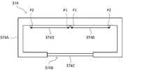
ここで、図1〜図3を参照しつつ、定着装置37について説明する。なお、図3は温度センサー374の断面模式図である。 Here, the fixing
図1に示されるように、定着装置37は、定着ローラー371、加圧ローラー372、熱源373、及び温度センサー374を備える。 As shown in FIG. 1, the fixing
定着ローラー371は、加熱された状態で回転するローラーである。また、加圧ローラー372は、定着ローラー371と当接した状態で回転するローラーである。例えば、定着ローラー371及び加圧ローラー372はゴムローラーである。例えば、加圧ローラー372は、不図示の付勢部材により定着ローラー371と対向する方向に向けて付勢される。これにより、定着ローラー371と加圧ローラー372との間で、所定の圧力を有するニップ部が形成される。 The fixing
熱源373は、定着ローラー371を加熱させる。例えば、熱源373は、図1に示されるように、定着ローラー371の内部に設けられる。例えば、熱源373は、ハロゲンヒーター又はIHヒーターである。熱源373は、不図示の電源回路から供給される駆動電力によって駆動されて、定着ローラー371を加熱させる。 The
画像形成部3では、転写ローラー35によってトナー像が転写されたシートが定着装置37の前記ニップ部に搬送される。これにより、シートに転写されたトナー像は、定着ローラー371及び加圧ローラー372によって加熱及び加圧されてシートに溶融定着する。ここに、定着ローラー371が、本発明における定着部材の一例である。 In the
温度センサー374は、図1に示されるように、定着ローラー371の表面から離間した位置に設けられたセンサーである。温度センサー374は、定着ローラー371の表面の温度を検出する。 The
図2及び図3に示されるように、温度センサー374は、ケーシング374A、開口部374B、透光部374C、熱電対374D、及び検出部374Eを備える。 As shown in FIGS. 2 and 3, the
ケーシング374Aは、熱電対374Dを収納する。ケーシング374Aは、図3に示されるように、開口部374Bを備える。温度センサー374は、開口部374Bが定着ローラー371の表面と対向する位置に配置される。 The
透光部374Cは、定着ローラー371の表面から放射される赤外線をケーシング374Aの内部に透過させる。図3に示されるように、透光部374Cは、開口部374Bに設けられる。例えば、透光部374Cは、光学フィルター及び集光レンズを備える。前記光学フィルターは、予め定められた波長の光(赤外線)を透過させる。前記集光レンズは、透光部374Cを通過する赤外線をケーシング374Aの内部に設けられた熱電対374Dの温接点P1(図3参照)に集光させる。 The
熱電対374Dは、図3に示されるように、ケーシング374Aの内部に複数設けられる。熱電対374Dは、図3に示されるように、温接点P1及び冷接点P2を有する。熱電対374Dは、温接点P1と冷接点P2との間に生じる熱起電力に応じた第1信号値を出力する。ここで、温接点P1は、透光部374Cを透過した赤外線が照射される位置に配置される。また、冷接点P2は、透光部374Cを透過した赤外線が照射されない位置に配置される。これにより、熱電対374Dは、定着ローラー371の表面から放射されて透光部374Cを透過した赤外線の受光量に応じた前記第1信号値を出力する。具体的に、熱電対374Dは、小数点以下の位を含む前記第1信号値を出力する。例えば、前記第1信号値は、最小値が0Vであって、最大値が3.3Vの電圧信号である。なお、ケーシング374A内に設けられる熱電対374Dの数は任意の数であってよい。 A plurality of
検出部374Eは、冷接点P2の温度を検出して検出温度に応じた第2信号値を出力する。例えば、検出部374Eは、ケーシング374Aの内部に設けられる。例えば、検出部374Eはサーミスターである。具体的に、検出部374Eは、小数点以下の位を含む前記第2信号値を出力する。例えば、前記第2信号値は、前記第1信号値と同様に、最小値が0Vであって、最大値が3.3Vの電圧信号である。 The
画像形成装置10では、熱電対374Dから出力される前記第1信号値、及び検出部374Eから出力される前記第2信号値に基づいて、定着ローラー371の温度が検出される。具体的に、画像形成装置10では、前記第1信号値及び前記第2信号値が代入される変数を含む温度算出用の2次以上の高次式が用いられて、定着ローラー371の温度が検出される。例えば、前記高次式は、5次以上の式である。 In the
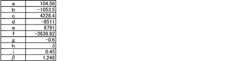
例えば、前記高次式は、以下に示す式(1)及び式(2)を含む。なお、式(1)において、Tは定着ローラー371の温度(℃)を示す。また、式(1)において、a、b、c、d、e、fは定数を示す。また、式(2)において、Vtoは前記第1信号値(V)を示し、Vtaは前記第2信号値(V)を示す。また、式(2)において、ΔVtoは予め定められた第1時間の間における前記第1信号値の変化量(V)を示し、ΔVtaは予め定められた第2時間の間における前記第2信号値の変化量(V)を示す。また、式(2)において、g、h、i、βは定数を示す。例えば、前記第1時間は200ミリ秒である。また、前記第2時間は10秒である。For example, the high-order equation includes the equations (1) and (2) shown below. In equation (1), T represents the temperature (° C.) of the fixing
T=aA5+bA4+cA3+dA2+eA+f・・・(1)T = aA5 + bA4 + cA3 + dA2 + eA + f (1)
A=Vto+(g×ΔVto)+(h×ΔVta)+(i×(Vta−β))・・・(2)A = Vto + (g × ΔVto ) + (h × ΔVta ) + (i × (Vta −β)) (2)
画像形成装置10では、式(1)及び式(2)に含まれる定数a、b、c、d、e、f、g、h、i、βの値が、記憶部7に格納されている。図4に、記憶部7に格納される定数a、b、c、d、e、f、g、h、i、βの一例を示す。図4に示されるように、定数a、b、c、f、g、i、βは小数点以下の位を含む値である。なお、定数a、b、c、d、e、f、g、h、i、βの値は、制御部5の前記ROM又は前記EEPROMに記憶されていてもよい。 In the
ところで、熱電対374Dから出力される第1信号値Vto、検出部374Eから出力される第2信号値Vta、並びに式(1)及び式(2)に含まれる定数に小数点以下の位が含まれる場合、小数点以下の位を含む値の演算処理を実行する制御部5の処理負荷が大きくなって、制御部5で実行される他の処理の実行速度が低下することがある。一方、小数点以下の位を排除するために第1信号値Vto、第2信号値Vta、並びに式(1)及び式(2)に含まれる定数の各々に10の累乗数が乗算されて、それらの値が予め整数に変換される場合は、演算処理において制御部5の処理負荷が大きい除算を行う必要がある。By the way, the first signal value Vto output from the
これに対し、本発明の実施形態に係る画像形成装置10では、以下に説明するように、熱電対374Dを用いて定着ローラー371の温度を検出する制御部5の処理負荷を軽減することが可能である。 On the other hand, in the
具体的に、制御部5の前記ROMには、前記CPUに後述の駆動制御処理(図6のフローチャート参照)及び温度算出処理(図7のフローチャート参照)を実行させるための駆動制御プログラムが予め記憶されている。なお、前記駆動制御プログラムは、CD、DVD、フラッシュメモリーなどのコンピューター読み取り可能な記録媒体に記録されており、前記記録媒体から読み取られて記憶部7にインストールされるものであってもよい。 Specifically, the ROM of the control unit 5 stores in advance a drive control program for causing the CPU to execute drive control processing (see the flowchart of FIG. 6) and temperature calculation processing (see the flowchart of FIG. 7) described later. It is done. The drive control program may be recorded in a computer readable recording medium such as a CD, a DVD, a flash memory, etc., and may be read from the recording medium and installed in the storage unit 7.
そして、制御部5は、図2に示されるように、変換処理部51、算出処理部52、及び駆動制御部53を含む。具体的に、制御部5は、前記CPUを用いて前記ROMに記憶されている前記駆動制御プログラムを実行する。これにより、制御部5は、変換処理部51、算出処理部52、及び駆動制御部53として機能する。ここに、温度センサー374及び制御部5を備える装置が、本発明における温度検出装置の一例である。 The control unit 5 includes a
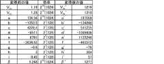
変換処理部51は、第1信号値Vto、第2信号値Vta、並びに式(1)及び式(2)に含まれる定数の各々に対して2の累乗数を乗算して、乗算結果各々をその乗算結果各々に近似した整数に変換する。The
例えば、変換処理部51は、予め定められた検出間隔ごとに、熱電対374D及び検出部374Eから第1信号値Vto及び第2信号値Vtaを取得する。例えば、前記取得間隔は100ミリ秒である。For example, the
そして、変換処理部51は、取得された第1信号値Vtoに対して210(=1024)を乗算して、乗算結果に含まれる小数点以下の位を切り捨てることで、第1信号値Vtoを整数に変換する。また、変換処理部51は、取得された第2信号値Vtaに対して210(=1024)を乗算して、乗算結果に含まれる小数点以下の位を切り捨てることで、第2信号値Vtaを整数に変換する。なお、変換処理部51は、乗算結果に含まれる小数点以下の位を切り上げ又は四捨五入して、第1信号値Vto及び第2信号値Vtaを整数に変換してもよい。Then, the
また、変換処理部51は、予め定められた制御開始条件を充足した場合に、記憶部7から式(1)及び式(2)に含まれる定数a、b、c、d、e、f、g、h、i、βを取得する。例えば、前記制御開始条件は、画像形成装置10の電源が投入されたこと、及び画像形成装置10の動作モードがスリープモードから通常モードに移行したことである。 In addition, when the
そして、変換処理部51は、取得された定数のうち、定数a、βに対して210(=1024)を乗算して、乗算結果に含まれる小数点以下の位を切り捨てることで、定数a、βを整数に変換する。また、変換処理部51は、取得された定数のうち、定数b、c、d、e、f、g、h、iに対して27(=128)を乗算して、乗算結果に含まれる小数点以下の位を切り捨てることで、定数b、c、d、e、f、g、h、iを整数に変換する。Then, the
図5に、変換処理部51による第1信号値Vto、第2信号値Vta、並びに式(1)及び式(2)に含まれる定数の変換例を示す。以下、変換処理部51による変換後の第1信号値Vto、第2信号値Vta、及び定数a、b、c、d、e、f、g、h、i、βを、それぞれ変換値Vto’、Vta’、a’、b’、c’、d’、e’、f’、g’、h’、i’、β’とする。FIG. 5 shows an example of conversion of the first signal value Vto and the second signal value Vta by the
算出処理部52は、式(1)及び式(2)を用いて定着ローラー371の温度を検出する。例えば、算出処理部52は、前記検出間隔ごとに、定着ローラー371の温度を検出する。 The
例えば、算出処理部52は、式(1)及び式(2)に含まれる定数が変換処理部51による変換後の定数に置換された第1変形式に、変換処理部51による変換後の第1信号値Vto及び第2信号値Vtaを代入すると共に、前記第1変形式に含まれる項各々に対して2の累乗数の乗算又は除算を行うことによって、定着ローラー371の温度を算出することが可能である。For example, the
具体的に、前記第1変形式は、以下の式(3)及び式(4)によって示される。 Specifically, the first modified equation is represented by the following equation (3) and equation (4).
a’B5+b’B4+c’B3+d’B2+e’B+f’・・・(3)a'B5 + b'B4 + c'B3 + d'B2 + e'B + f '(3)
B=Vto’+(g’×ΔVto’)+(h’×ΔVta’)+(i’×(Vta’−β’))・・・(4)B = Vto '+ (g' × ΔVto ') + (h' × ΔVta ') + (i' × (Vta '-β')) (4)
ここで、以下の式(5)に示すように、式(4)に含まれる項各々に対して2の累乗数の乗算又は除算を行うことで、式(2)によって算出されるAに2の累乗数が乗算された値B’(B’=212A)を算出することが可能である。Here, as shown in the following equation (5), by performing multiplication or division of the power of 2 on each of the terms included in the equation (4), A calculated by the equation (2) is 2 It is possible to calculate the value B ′ (B ′ = 212 A) multiplied by the power of
B’=22Vto’+2-5(g’×ΔVto’)+2-5(h’×ΔVta’)+2-5(i’×(Vta’−β’))・・・(5)B '= 22 Vto ' +2-5 (g 'x? Vto ') +2-5 (h 'x? Vta ') +2-5 (i 'x (Vta'- ? ')) 5)
また、以下の式(6)に示すように、式(3)に含まれるBを式(5)により算出されるB’に置換すると共に、項各々に対して2の累乗数の除算を行うことで、定着ローラー371の温度Tを算出することが可能である。 Further, as shown in the following equation (6), B included in the equation (3) is replaced with B 'calculated by the equation (5), and division of 2's power is performed on each of the terms Thus, it is possible to calculate the temperature T of the fixing
T=2-70a’(B’)5+2-55b’(B’)4+2-43c’(B’)3+2-31d’(B’)2+2-19e’B’+2-7f’・・・(6)T = 2 -70 a '(B ') 5 +2 -55 b '(B') 4 +2 -43 c '(B') 3 +2 -31 d '(B') 2 +2 -19 e'B '+ 2-7 f '(6)
一方、算出処理部52は、前記第1変形式が因数分解された第2変形式に、変換処理部51による変換後の第1信号値Vto及び第2信号値Vtaを代入して、前記第2変形式に含まれる低次式から順に演算処理を行うと共に、前記第2変形式に含まれる項各々に対して2の累乗数の乗算又は除算を行うことによって、定着ローラー371の温度を算出することも可能である。On the other hand, the
具体的に、式(3)を因数分解することで、以下に示す式(7)が得られる。 Specifically, equation (7) shown below is obtained by factoring equation (3).
B(B(B(B(Ba’+b’)+c’)+d’)+e’)+f’・・・(7) B (B (B (B (Ba '+ b') + c ') + d') + e ') + f' ... (7)
ここで、以下の式(8)に示すように、式(7)に含まれるBを式(5)により算出されるB’に置換すると共に、項各々に対して2の累乗数の乗算又は除算を行うことで、定着ローラー371の温度Tを算出することが可能である。 Here, as shown in the following equation (8), B contained in the equation (7) is replaced by B ′ calculated by the equation (5), and multiplication of a power of 2 for each of the terms or By performing the division, it is possible to calculate the temperature T of the fixing
T=2-19(2-12B’(2-12B’(2-12B’(2-12B’(2-3B’a’+212b’)+212c’)+212d’)+212e’)+212f’)・・・(8)T = 2 -19 (2 -12 B '(2 -12 B' (2 -12 B '(2 -12 B' (2 -3 B'a '+ 2 12 b') + 2 12 c ') + 2 12 d ') + 212 e') + 212 f ') (8)
具体的に、算出処理部52は、式(8)に含まれる1次式(9)、2次式(10)、3次式(11)、4次式(12)、及び5次式(13)を順次演算して、5次式(13)の演算結果に対して219の除算を行うことで、定着ローラー371の温度Tを算出することが可能である。Specifically, the
(2-3B’a’+212b’)・・・(9)(2 -3 B'a '+ 2 12 b') ··· (9)
(2-12B’(2-3B’a’+212b’)+212c’)・・・(10)(2 -12 B '(2 -3 B'a' + 2 12 b ') + 2 12 c') ··· (10)
(2-12B’(2-12B’(2-3B’a’+212b’)+212c’)+212d’)・・・(11)(2 -12 B '(2 -12 B' (2 -3 B'a '+ 2 12 b') + 2 12 c ') + 2 12 d') ··· (11)
(2-12B’(2-12B’(2-12B’(2-3B’a’+212b’)+212c’)+212d’)+212e’)・・・(12)(2-12 B '(2-12 B' (2-12 B '(2-3 B'a' + 212 b ') + 212 c') + 212 d ') + 212 e') ... (( 12)
(2-12B’(2-12B’(2-12B’(2-12B’(2-3B’a’+212b’)+212c’)+212d’)+212e’)+212f’)・・・(13)(2 -12 B '(2 -12 B' (2 -12 B '(2 -12 B' (2 -3 B'a '+ 2 12 b') + 2 12 c ') + 2 12 d') + 2 12 e ') + 212 f') (13)
画像形成装置10では、算出処理部52が、式(8)を用いて、定着ローラー371の温度Tを算出する。これにより、定着ローラー371の温度Tの算出に式(6)が用いられる場合と比較して、演算過程で取得される値の桁数を抑制することが可能である。即ち、算出処理部52の演算可能桁数が少ない場合であっても、定着ローラー371の温度Tを算出することが可能である。 In the
なお、変換処理部51による第1信号値Vto、第2信号値Vta、並びに式(1)及び式(2)に含まれる定数の各々に対する2の累乗数の乗算における乗数は、算出処理部52の演算可能桁数及び演算過程における有効数字の桁数等を考慮して、任意の数に設定されてよい。同様に、算出処理部52による式(5)、及び式(8)における項各々に対する2の累乗数の乗算又は除算における乗数又は除数も、算出処理部52の演算可能桁数及び演算過程における有効数字の桁数等を考慮して、任意の数に設定されてよい。また、算出処理部52は、式(6)を用いて定着ローラー371の温度Tを算出してもよい。Note that the multiplier in the multiplication of the second power of 2 by each of the first signal value Vto and the second signal value Vta by the
例えば、算出処理部52は、式(8)を用いて算出された値に含まれる小数点以下の位を切り捨てることで、定着ローラー371の温度Tを算出する。 For example, the
駆動制御部53は、算出処理部52によって算出された定着ローラー371の温度Tに基づいて、熱源373の駆動を制御する。例えば、駆動制御部53は、定着ローラー371の温度Tが予め定められた基準温度となるように、熱源373の駆動を制御する。例えば、前記基準温度は200℃である。具体的に、駆動制御部53は、前記電源回路から熱源373に供給される駆動電力を調整することによって、熱源373の駆動を制御する。 The
[駆動制御処理]
以下、図6を参照しつつ、画像形成装置10において制御部5により実行される駆動制御処理の手順の一例と共に、本発明における温度検出方法の手順の一例について説明する。ここで、ステップS11、S12・・・は、制御部5により実行される処理手順(ステップ)の番号を表している。[Drive control processing]
Hereinafter, an example of the procedure of the temperature detection method in the present invention will be described together with an example of the procedure of the drive control process executed by the control unit 5 in the
<ステップS11>
まず、ステップS11において、制御部5は、前記制御開始条件を充足したか否かを判断する。<Step S11>
First, in step S11, the control unit 5 determines whether the control start condition is satisfied.
ここで、制御部5は、前記制御開始条件を充足したと判断すると(S11のYes側)、処理をステップS12に移行させる。また、前記制御開始条件を充足していなければ(S11のNo側)、制御部5は、ステップS11で前記制御開始条件の充足を待ち受ける。 Here, when the control unit 5 determines that the control start condition is satisfied (Yes in S11), the control unit 5 shifts the process to step S12. If the control start condition is not satisfied (No in S11), the control unit 5 waits for the control start condition to be satisfied in step S11.
<ステップS12>
ステップS12において、制御部5は、記憶部7から式(1)及び式(2)に含まれる定数a、b、c、d、e、f、g、h、i、βを取得する。<Step S12>
In step S12, the control unit 5 acquires the constants a, b, c, d, e, f, g, h, i, β contained in the equations (1) and (2) from the storage unit 7.
<ステップS13>
ステップS13において、制御部5は、ステップS12で取得された定数を整数に変換する。<Step S13>
In step S13, the control unit 5 converts the constant acquired in step S12 into an integer.
具体的に、制御部5は、ステップS12で取得された定数のうち、定数a、βに対して210(=1024)を乗算して、乗算結果に含まれる小数点以下の位を切り捨てることで、定数a、βを変換値a’、β’に変換する。また、制御部5は、ステップS12で取得された定数のうち、定数b、c、d、e、f、g、h、iに対して27(=128)を乗算して、乗算結果に含まれる小数点以下の位を切り捨てることで、定数b、c、d、e、f、g、h、iを変換値b’、c’、d’、e’、f’、g’、h’、i’に変換する。Specifically, the control unit 5 multiplies the constants a and β by 210 (= 1024) out of the constants acquired in step S12, and discards the decimal places included in the multiplication result. , Constants a, β are converted to converted values a ′, β ′. Further, the control unit 5 multiplies the constants b, c, d, e, f, g, h and i among the constants obtained in step S12 by 27 (= 128), Constants b, c, d, e, f, g, h, i converted values b ', c', d ', e', f ', f', g ', h' by truncating the decimal places included , I 'to convert.
<ステップS14>
ステップS14において、制御部5は、熱電対374D及び検出部374Eから第1信号値Vto及び第2信号値Vtaを取得する。<Step S14>
In step S14, the control unit 5 acquires a first signal value Vto and the second signal value Vta from the
<ステップS15>
ステップS15において、制御部5は、ステップS14で取得された第1信号値Vto及び第2信号値Vtaを整数に変換する。ここに、ステップS12からステップS15までの処理が、本発明における第1ステップの一例であって、制御部5の変換処理部51により実行される。<Step S15>
In step S15, the control unit 5 converts the first signal valueVto and the second signal valueVta acquired in step S14 into integers. Here, the processing from step S12 to step S15 is an example of the first step in the present invention, and is executed by the
具体的に、制御部5は、ステップS14で取得された第1信号値Vtoに対して210(=1024)を乗算して、乗算結果に含まれる小数点以下の位を切り捨てることで、第1信号値Vtoを変換値Vto’に変換する。また、制御部5は、ステップS14で取得された第2信号値Vtaに対して210(=1024)を乗算して、乗算結果に含まれる小数点以下の位を切り捨てることで、第2信号値Vtaを変換値Vta’に変換する。Specifically, the control unit 5 multiplies the first signal value Vto obtained in step S 14 by 210 (= 1024), and discards the decimal places included in the multiplication result. 1. Convert the signal value Vto into a converted value Vto '. In addition, the control unit 5 multiplies the second signal valueVta acquired in step S14 by 210 (= 1024), and discards the decimal place included in the multiplication result, thereby the second signal Convert the value Vta into a converted value Vta '.
<ステップS16>
ステップS16において、制御部5は、以下に述べる温度算出処理を実行する。ここに、ステップS16の処理が、本発明における第2ステップであって、制御部5の算出処理部52により実行される。<Step S16>
In step S16, the control unit 5 executes a temperature calculation process described below. Here, the process of step S16 is a second step in the present invention, and is executed by the
[温度算出処理]
ここで、図7を参照しつつ、前記駆動制御処理のステップS16で実行される前記温度算出処理の手順の一例について説明する。なお、前記駆動制御処理のステップS17以降の処理の説明は、前記温度算出処理の説明の終了後に行う。また、以下においては、ΔVto及びΔVtaが0であると仮定して説明を行う。[Temperature calculation processing]
Here, an example of the procedure of the temperature calculation process executed in step S16 of the drive control process will be described with reference to FIG. The process of step S17 and subsequent steps of the drive control process will be described after the description of the temperature calculation process is completed. Also, in the following description, it is assumed that ΔVto and ΔVta are zero.
<ステップS21>
まず、ステップS21において、制御部5は、式(5)に従ってB’の値を算出する。例えば、制御部5は、図5に示される定数g’、h’、i’、β’を含む式(5)に、図5に示される変換値Vto’、Vta’を代入して、B’の値を4,930と算出する。<Step S21>
First, in step S21, the control unit 5 calculates the value of B 'according to equation (5). For example, the control unit 5 substitutes the conversion values Vto 'and Vta ' shown in FIG. 5 into the equation (5) including the constants g ', h', i 'and β' shown in FIG. The value of B ′ is calculated as 4,930.
ここで、式(5)には25の除算が含まれている。しかしながら、25の除算はビット演算により処理することが可能である。従って、第1信号値Vto、第2信号値Vta、並びに式(1)及び式(2)に含まれる定数の各々に対して10の累乗数の乗算を行い、その後の演算過程において10の累乗数の除算を行う場合と比較して、制御部5の処理負荷が軽減される。Here, equation (5) includes25 divisions. However,25 divisions can be processed by bit operations. Therefore, multiplication of a power of 10 is performed on each of the first signal value Vto , the second signal value Vta , and the constants included in the equations (1) and (2), and The processing load of the control unit 5 is reduced as compared with the case of dividing the power of.
<ステップS22>
ステップS22において、制御部5は、1次式(9)を演算する。例えば、制御部5は、図5に示される定数a’、b’を含む1次式(9)に、ステップS21で算出されたB’の値を代入して、−486,356,137の値を算出する。<Step S22>
In step S22, the control unit 5 calculates a linear expression (9). For example, the control unit 5 substitutes the value of B ′ calculated in step S21 into the linear expression (9) including the constants a ′ and b ′ shown in FIG. Calculate the value.
ここで、1次式(9)には23の除算が含まれている。しかしながら、23の除算はビット演算により処理することが可能である。Here, it contains
<ステップS23>
ステップS23において、制御部5は、2次式(10)を演算する。例えば、制御部5は、図5に示される定数a’、b’、c’を含む2次式(10)に、ステップS21で算出されたB’の値、及びステップS22による算出結果を代入して、1,631,513,855の値を算出する。<Step S23>
In step S23, the control unit 5 calculates a quadratic expression (10). For example, the control unit 5 substitutes the value of B 'calculated in step S21 and the calculation result in step S22 into the quadratic expression (10) including the constants a', b 'and c' shown in FIG. Then, the values of 1,631, 513, 855 are calculated.
ここで、2次式(10)には212の除算が含まれている。しかしながら、212の除算はビット演算により処理することが可能である。なお、制御部5は、ステップS22による算出結果に対して、まず212の除算を行った後に、ステップS21で算出されたB’の値を乗算する。これにより、逆の順序で演算を行った場合と比較して、演算過程で得られる値の桁数が抑えられる。Here, the quadratic equation (10) includes a division of 212. However, the division of 212 can be processed by the bit operation. The control unit 5, to the calculation result in step S22, first, after the division of 212, multiplies the value of the calculated B 'in step S21. Thereby, the number of digits of the value obtained in the calculation process can be suppressed as compared with the case where the calculation is performed in the reverse order.
<ステップS24>
ステップS24において、制御部5は、3次式(11)を演算する。例えば、制御部5は、図5に示される定数a’、b’、c’、d’を含む3次式(11)に、ステップS21で算出されたB’の値、及びステップS23による算出結果を代入して、−2,498,503,424の値を算出する。<Step S24>
In step S24, the control unit 5 calculates a cubic expression (11). For example, the control unit 5 calculates the value of B 'calculated in step S21 and the calculation of step S23 in the cubic expression (11) including the constants a', b ', c' and d 'shown in FIG. Substituting the result, the values of -2, 498, 503 and 424 are calculated.
ここで、3次式(11)には212の除算が含まれている。しかしながら、212の除算はビット演算により処理することが可能である。なお、制御部5は、ステップS23による算出結果に対して、まず212の除算を行った後に、ステップS21で算出されたB’の値を乗算する。Here, it contains
<ステップS25>
ステップS25において、制御部5は、4次式(12)を演算する。例えば、制御部5は、図5に示される定数a’、b’、c’、d’、e’を含む4次式(12)に、ステップS21で算出されたB’の値、及びステップS24による算出結果を代入して、1,601,783,904の値を算出する。<Step S25>
In step S25, the control unit 5 calculates a quaternary equation (12). For example, the control unit 5 sets the value of B 'calculated in step S21 to the quaternary expression (12) including the constants a', b ', c', d ', and e' shown in FIG. By substituting the calculation result of S24, the values of 1,601,783,904 are calculated.
ここで、4次式(12)には212の除算が含まれている。しかしながら、212の除算はビット演算により処理することが可能である。なお、制御部5は、ステップS24による算出結果に対して、まず212の除算を行った後に、ステップS21で算出されたB’の値を乗算する。Here, it contains
<ステップS26>
ステップS26において、制御部5は、5次式(13)を演算する。例えば、制御部5は、図5に示される定数a’、b’、c’、d’、e’、f’を含む5次式(13)に、ステップS21で算出されたB’の値、及びステップS25による算出結果を代入して、21,191,228の値を算出する。<Step S26>
In step S26, the control unit 5 calculates a fifth expression (13). For example, the control unit 5 sets the value of B 'calculated in step S21 to a fifth-order equation (13) including the constants a', b ', c', d ', e', and f 'shown in FIG. , And the calculation results of step S25 are substituted to calculate values of 21, 191, and 228.
ここで、5次式(13)には212の除算が含まれている。しかしながら、212の除算はビット演算により処理することが可能である。なお、制御部5は、ステップS25による算出結果に対して、まず212の除算を行った後に、ステップS21で算出されたB’の値を乗算する。Here, the fifth-order equation (13) contains the division of 212. However, the division of 212 can be processed by the bit operation. The control unit 5, to the calculation result of step S25, first, after the division of 212, multiplies the value of the calculated B 'in step S21.
<ステップS27>
ステップS27において、制御部5は、定着ローラー371の温度Tを算出する。例えば、制御部5は、ステップS26による算出結果に対して219の除算を行い、除算結果に含まれる小数点以下の位を切り捨てることで、定着ローラー371の温度Tが40(℃)であると算出する。<Step S27>
In step S27, the control unit 5 calculates the temperature T of the fixing
以上で、前記温度算出処理の説明を終了して、前記駆動制御処理のステップS17以降の処理の説明を再開する。 This is the end of the description of the temperature calculation process, and the description of the process after step S17 of the drive control process is resumed.
<ステップS17>
ステップS17において、制御部5は、ステップS16で算出された定着ローラー371の温度Tに基づいて、定着ローラー371の温度Tが前記基準温度となるように、熱源373の駆動を制御する。具体的に、制御部5は、前記電源回路から熱源373に供給される駆動電力を調整することによって、熱源373の駆動を制御する。ここで、ステップS17の処理は、制御部5の駆動制御部53により実行される。<Step S17>
In step S17, based on the temperature T of the fixing
<ステップS18>
ステップS18において、制御部5は、予め定められた制御終了条件を充足したか否かを判断する。例えば、前記制御終了条件は、画像形成装置10の電源が遮断されたこと、及び前記動作モードが通常モードからスリープモードに移行したことである。<Step S18>
In step S18, control unit 5 determines whether or not a predetermined control termination condition is satisfied. For example, the control termination condition is that the power supply of the
ここで、制御部5は、前記制御終了条件を充足したと判断すると(S18のYes側)、処理をステップS11に移行させる。また、前記制御終了条件を充足していなければ(S18のNo側)、制御部5は、ステップS14の処理の実行時から前記検出間隔に対応する時間が経過したタイミングで処理をステップS14に移行させる。これにより、前記制御終了条件が充足されるまでの間、定着ローラー371の温度が前記基準温度に維持される。 Here, when the control unit 5 determines that the control end condition is satisfied (Yes in S18), the control unit 5 shifts the process to step S11. Further, if the control end condition is not satisfied (No in S18), the control unit 5 shifts the processing to step S14 at the timing when the time corresponding to the detection interval has elapsed from the execution of the processing in step S14. Let Thus, the temperature of the fixing
このように、画像形成装置10では、熱電対374Dから出力される第1信号値Vto、検出部374Eから出力される第2信号値Vta、並びに式(1)及び式(2)に含まれる定数に2の累乗数が乗算されて、乗算結果各々がその乗算結果各々に近似した整数に変換される。そして、変換後の定数を含む式(1)及び式(2)の変形式に変換後の第1信号値Vto及び第2信号値Vtaが代入されると共に、変形式に含まれる項各々に対して2の累乗数の乗算又は除算が行われることで、定着ローラー371の温度Tが算出される。これにより、定着ローラー371の温度Tの算出過程において小数点を含む演算を排除することが可能となる。また、第1信号値Vto、第2信号値Vta、及び定数の整数への変換処理に伴って温度Tの算出過程に生じる除算が2の累乗数の除算となるため、ビット演算を用いて処理することが可能である。従って、熱電対374Dを用いて定着ローラー371の温度Tを検出する制御部5の処理負荷を軽減することが可能である。As described above, in the
1 ADF
2 画像読取部
3 画像形成部
4 給紙部
5 制御部
6 操作表示部
7 記憶部
10 画像形成装置
37 定着装置
51 変換処理部
52 算出処理部
53 駆動制御部
371 定着ローラー
372 加圧ローラー
373 熱源
374 温度センサー
374D 熱電対
374E 検出部1 ADF
Claims (5)
Translated fromJapanese前記冷接点の温度を検出して検出温度に応じた第2信号値を出力する検出部と、を備え、前記第1信号値及び前記第2信号値が代入される変数を含む温度算出用の2次以上の高次式を用いてトナー像の定着に用いられる定着部材の温度を検出する温度検出装置であって、
前記第1信号値、前記第2信号値、及び前記高次式に含まれる定数のいずれか一つ又は複数に小数点以下の位が含まれており、
前記第1信号値、前記第2信号値、及び前記定数の各々に対して2の累乗数を乗算して、乗算結果各々を前記乗算結果各々に近似した整数に変換する変換処理部と、
前記高次式において前記定数が前記変換処理部による変換後の前記定数に置換された第1変形式に前記変換処理部による変換後の前記第1信号値及び前記第2信号値を代入すると共に、前記第1変形式に含まれる項各々に対して2の累乗数の乗算又は除算を行うことによって前記定着部材の温度を算出する算出処理部と、
を備える温度検出装置。A thermocouple having a hot junction and a cold junction and outputting a first signal value according to a thermoelectromotive force generated between the hot junction and the cold junction;
And a detection unit for detecting the temperature of the cold junction and outputting a second signal value corresponding to the detected temperature, for calculating temperature including a variable to which the first signal value and the second signal value are substituted. A temperature detection device for detecting the temperature of a fixing member used for fixing a toner image by using a second or higher order equation.
Any one or more of the first signal value, the second signal value, and the constant included in the high-order equation include decimal places.
A conversion processing unit that multiplies each of the first signal value, the second signal value, and the constant by a power of 2 and converts each of the multiplication results into an integer approximated to each of the multiplication results;
The first signal value and the second signal value after conversion by the conversion processing unit are substituted into a first modified equation in which the constant is replaced by the constant after conversion by the conversion processing unit in the high-order equation. A calculation processing unit that calculates the temperature of the fixing member by performing multiplication or division of a power of 2 on each of the terms included in the first modification;
Temperature detection device comprising:
前記第1信号値、前記第2信号値、及び前記高次式に含まれる定数のいずれか一つ又は複数に小数点以下の位が含まれており、
前記第1信号値、前記第2信号値、及び前記定数の各々に対して2の累乗数を乗算して、乗算結果各々を前記乗算結果各々に近似した整数に変換する第1ステップと、
前記高次式において前記定数が前記第1ステップによる変換後の前記定数に置換された第1変形式に前記第1ステップによる変換後の前記第1信号値及び前記第2信号値を代入すると共に、前記第1変形式に含まれる項各々に対して2の累乗数の乗算又は除算を行うことによって前記定着部材の温度を算出する第2ステップと、
を含む温度検出方法。A thermocouple having a hot junction and a cold junction and outputting a first signal value corresponding to a thermoelectromotive force generated between the hot junction and the cold junction, and detecting a temperature of the cold junction to detect the detected temperature And a detection unit for outputting a second signal value corresponding to the second image value, and using a second or higher order equation for temperature calculation including a variable to which the first signal value and the second signal value are substituted. A temperature detection method implemented by a temperature detection device for detecting the temperature of a fixing member used for fixing
Any one or more of the first signal value, the second signal value, and the constant included in the high-order equation include decimal places.
A first step of multiplying each of the first signal value, the second signal value, and the constant by a power of 2 and converting each of the multiplication results into an integer approximated to each of the multiplication results;
The first signal value and the second signal value after conversion by the first step are substituted into a first modified equation in which the constant is replaced by the constant after the conversion by the first step in the high order expression. A second step of calculating the temperature of the fixing member by performing multiplication or division of a power of 2 on each of the terms included in the first modification;
Temperature detection method including:
Priority Applications (2)
| Application Number | Priority Date | Filing Date | Title |
|---|---|---|---|
| JP2016091140AJP6544290B2 (en) | 2016-04-28 | 2016-04-28 | Temperature detection apparatus, image forming apparatus, temperature detection method |
| US15/497,012US10168230B2 (en) | 2016-04-28 | 2017-04-25 | Temperature detection device, electrophotographic type image forming apparatus, and temperature detection method |
Applications Claiming Priority (1)
| Application Number | Priority Date | Filing Date | Title |
|---|---|---|---|
| JP2016091140AJP6544290B2 (en) | 2016-04-28 | 2016-04-28 | Temperature detection apparatus, image forming apparatus, temperature detection method |
Publications (2)
| Publication Number | Publication Date |
|---|---|
| JP2017198912A JP2017198912A (en) | 2017-11-02 |
| JP6544290B2true JP6544290B2 (en) | 2019-07-17 |
Family
ID=60157380
Family Applications (1)
| Application Number | Title | Priority Date | Filing Date |
|---|---|---|---|
| JP2016091140AActiveJP6544290B2 (en) | 2016-04-28 | 2016-04-28 | Temperature detection apparatus, image forming apparatus, temperature detection method |
Country Status (2)
| Country | Link |
|---|---|
| US (1) | US10168230B2 (en) |
| JP (1) | JP6544290B2 (en) |
Family Cites Families (10)
| Publication number | Priority date | Publication date | Assignee | Title |
|---|---|---|---|---|
| JP2797736B2 (en)* | 1991-02-21 | 1998-09-17 | キヤノン株式会社 | Fixing device |
| JPH0666639A (en)* | 1992-08-20 | 1994-03-11 | Toyota Central Res & Dev Lab Inc | Infrared thermometer |
| US5836692A (en)* | 1994-03-30 | 1998-11-17 | Exergen Corporation | Differential radiation detector probe |
| JPH0862047A (en)* | 1994-08-23 | 1996-03-08 | Casio Comput Co Ltd | Temperature measuring device |
| JP2002228523A (en)* | 2001-02-05 | 2002-08-14 | Nippon Ceramic Co Ltd | Temperature calculating method for non-contact type temperature detector |
| JP3669347B2 (en)* | 2002-06-10 | 2005-07-06 | ブラザー工業株式会社 | Image forming apparatus and thermal fixing apparatus |
| JP2004191075A (en)* | 2002-12-06 | 2004-07-08 | Matsushita Electric Ind Co Ltd | Temperature measuring device, temperature correcting method, and image forming apparatus |
| JP2004325637A (en)* | 2003-04-23 | 2004-11-18 | Canon Inc | Image forming device |
| JP5530274B2 (en)* | 2010-06-30 | 2014-06-25 | パナソニック株式会社 | Temperature sensor |
| JP6197312B2 (en)* | 2013-03-12 | 2017-09-20 | 株式会社リコー | Sensor element and method for manufacturing sensor element |
- 2016
- 2016-04-28JPJP2016091140Apatent/JP6544290B2/enactiveActive
- 2017
- 2017-04-25USUS15/497,012patent/US10168230B2/enactiveActive
Also Published As
| Publication number | Publication date |
|---|---|
| US10168230B2 (en) | 2019-01-01 |
| JP2017198912A (en) | 2017-11-02 |
| US20170314999A1 (en) | 2017-11-02 |
Similar Documents
| Publication | Publication Date | Title |
|---|---|---|
| US8948640B2 (en) | Image forming apparatus | |
| JP4389542B2 (en) | Image forming apparatus | |
| CN106842862B (en) | Fixing device and image forming device | |
| US9819826B2 (en) | Image forming apparatus that controls image forming conditions for adjusting image density | |
| JP6544290B2 (en) | Temperature detection apparatus, image forming apparatus, temperature detection method | |
| JP6075007B2 (en) | Recording medium thickness detection apparatus, image forming apparatus, recording medium thickness detection method, and program | |
| JP6988257B2 (en) | Fixing device and image forming device | |
| JP6225575B2 (en) | Fixing apparatus, image forming apparatus, fixing method, and program | |
| JP2022155330A (en) | Image forming apparatus and its control method | |
| JP6907808B2 (en) | Fixing device and image forming device | |
| JP4093180B2 (en) | Image forming apparatus | |
| JP4595404B2 (en) | Image forming apparatus | |
| JP2002365966A (en) | Fixing device and image forming apparatus provided with the fixing device | |
| US11294312B2 (en) | Image forming apparatus to accurately determine temperature of heating member | |
| JP2003014557A (en) | Temperature detecting device, fixing device, and image forming device | |
| JP4338474B2 (en) | Fixing device, image forming apparatus, and fixing device control method | |
| JP7091682B2 (en) | Image forming device and control method | |
| JP2007226151A (en) | Fixing apparatus and image forming apparatus | |
| JP2003195679A (en) | Fixing device and image forming apparatus provided with the fixing device | |
| JP2000259035A (en) | Image forming device | |
| JP2003014558A (en) | Temperature detecting device, fixing device, and image forming device | |
| JP2018010024A (en) | Image forming apparatus and method for determining amount of developer | |
| JP2002333793A (en) | Temperature detection sensor, fixing device, and image forming device | |
| JP2025077170A (en) | Fixing device | |
| JP2007140400A (en) | Image forming apparatus and its fixing device control method |
Legal Events
| Date | Code | Title | Description |
|---|---|---|---|
| A621 | Written request for application examination | Free format text:JAPANESE INTERMEDIATE CODE: A621 Effective date:20180226 | |
| A977 | Report on retrieval | Free format text:JAPANESE INTERMEDIATE CODE: A971007 Effective date:20181105 | |
| A131 | Notification of reasons for refusal | Free format text:JAPANESE INTERMEDIATE CODE: A131 Effective date:20181204 | |
| TRDD | Decision of grant or rejection written | ||
| A01 | Written decision to grant a patent or to grant a registration (utility model) | Free format text:JAPANESE INTERMEDIATE CODE: A01 Effective date:20190521 | |
| A61 | First payment of annual fees (during grant procedure) | Free format text:JAPANESE INTERMEDIATE CODE: A61 Effective date:20190603 | |
| R150 | Certificate of patent or registration of utility model | Ref document number:6544290 Country of ref document:JP Free format text:JAPANESE INTERMEDIATE CODE: R150 |