JP6542708B2 - Display device - Google Patents
Display deviceDownload PDFInfo
- Publication number
- JP6542708B2 JP6542708B2JP2016085769AJP2016085769AJP6542708B2JP 6542708 B2JP6542708 B2JP 6542708B2JP 2016085769 AJP2016085769 AJP 2016085769AJP 2016085769 AJP2016085769 AJP 2016085769AJP 6542708 B2JP6542708 B2JP 6542708B2
- Authority
- JP
- Japan
- Prior art keywords
- curve
- vehicle
- display
- road
- road condition
- Prior art date
- Legal status (The legal status is an assumption and is not a legal conclusion. Google has not performed a legal analysis and makes no representation as to the accuracy of the status listed.)
- Active
Links
Images


Classifications
- G—PHYSICS
- G06—COMPUTING OR CALCULATING; COUNTING
- G06V—IMAGE OR VIDEO RECOGNITION OR UNDERSTANDING
- G06V20/00—Scenes; Scene-specific elements
- G06V20/50—Context or environment of the image
- G06V20/56—Context or environment of the image exterior to a vehicle by using sensors mounted on the vehicle
- G06V20/588—Recognition of the road, e.g. of lane markings; Recognition of the vehicle driving pattern in relation to the road
- B—PERFORMING OPERATIONS; TRANSPORTING
- B60—VEHICLES IN GENERAL
- B60K—ARRANGEMENT OR MOUNTING OF PROPULSION UNITS OR OF TRANSMISSIONS IN VEHICLES; ARRANGEMENT OR MOUNTING OF PLURAL DIVERSE PRIME-MOVERS IN VEHICLES; AUXILIARY DRIVES FOR VEHICLES; INSTRUMENTATION OR DASHBOARDS FOR VEHICLES; ARRANGEMENTS IN CONNECTION WITH COOLING, AIR INTAKE, GAS EXHAUST OR FUEL SUPPLY OF PROPULSION UNITS IN VEHICLES
- B60K35/00—Instruments specially adapted for vehicles; Arrangement of instruments in or on vehicles
- B60K35/20—Output arrangements, i.e. from vehicle to user, associated with vehicle functions or specially adapted therefor
- B60K35/21—Output arrangements, i.e. from vehicle to user, associated with vehicle functions or specially adapted therefor using visual output, e.g. blinking lights or matrix displays
- B60K35/22—Display screens
- B—PERFORMING OPERATIONS; TRANSPORTING
- B60—VEHICLES IN GENERAL
- B60K—ARRANGEMENT OR MOUNTING OF PROPULSION UNITS OR OF TRANSMISSIONS IN VEHICLES; ARRANGEMENT OR MOUNTING OF PLURAL DIVERSE PRIME-MOVERS IN VEHICLES; AUXILIARY DRIVES FOR VEHICLES; INSTRUMENTATION OR DASHBOARDS FOR VEHICLES; ARRANGEMENTS IN CONNECTION WITH COOLING, AIR INTAKE, GAS EXHAUST OR FUEL SUPPLY OF PROPULSION UNITS IN VEHICLES
- B60K35/00—Instruments specially adapted for vehicles; Arrangement of instruments in or on vehicles
- B60K35/20—Output arrangements, i.e. from vehicle to user, associated with vehicle functions or specially adapted therefor
- B60K35/28—Output arrangements, i.e. from vehicle to user, associated with vehicle functions or specially adapted therefor characterised by the type of the output information, e.g. video entertainment or vehicle dynamics information; characterised by the purpose of the output information, e.g. for attracting the attention of the driver
- B—PERFORMING OPERATIONS; TRANSPORTING
- B60—VEHICLES IN GENERAL
- B60R—VEHICLES, VEHICLE FITTINGS, OR VEHICLE PARTS, NOT OTHERWISE PROVIDED FOR
- B60R1/00—Optical viewing arrangements; Real-time viewing arrangements for drivers or passengers using optical image capturing systems, e.g. cameras or video systems specially adapted for use in or on vehicles
- B60R1/20—Real-time viewing arrangements for drivers or passengers using optical image capturing systems, e.g. cameras or video systems specially adapted for use in or on vehicles
- B60R1/22—Real-time viewing arrangements for drivers or passengers using optical image capturing systems, e.g. cameras or video systems specially adapted for use in or on vehicles for viewing an area outside the vehicle, e.g. the exterior of the vehicle
- B60R1/23—Real-time viewing arrangements for drivers or passengers using optical image capturing systems, e.g. cameras or video systems specially adapted for use in or on vehicles for viewing an area outside the vehicle, e.g. the exterior of the vehicle with a predetermined field of view
- B60R1/27—Real-time viewing arrangements for drivers or passengers using optical image capturing systems, e.g. cameras or video systems specially adapted for use in or on vehicles for viewing an area outside the vehicle, e.g. the exterior of the vehicle with a predetermined field of view providing all-round vision, e.g. using omnidirectional cameras
- B—PERFORMING OPERATIONS; TRANSPORTING
- B60—VEHICLES IN GENERAL
- B60R—VEHICLES, VEHICLE FITTINGS, OR VEHICLE PARTS, NOT OTHERWISE PROVIDED FOR
- B60R1/00—Optical viewing arrangements; Real-time viewing arrangements for drivers or passengers using optical image capturing systems, e.g. cameras or video systems specially adapted for use in or on vehicles
- B60R1/20—Real-time viewing arrangements for drivers or passengers using optical image capturing systems, e.g. cameras or video systems specially adapted for use in or on vehicles
- B60R1/31—Real-time viewing arrangements for drivers or passengers using optical image capturing systems, e.g. cameras or video systems specially adapted for use in or on vehicles providing stereoscopic vision
- B—PERFORMING OPERATIONS; TRANSPORTING
- B62—LAND VEHICLES FOR TRAVELLING OTHERWISE THAN ON RAILS
- B62D—MOTOR VEHICLES; TRAILERS
- B62D6/00—Arrangements for automatically controlling steering depending on driving conditions sensed and responded to, e.g. control circuits
- B62D6/001—Arrangements for automatically controlling steering depending on driving conditions sensed and responded to, e.g. control circuits the torque NOT being among the input parameters
- G—PHYSICS
- G01—MEASURING; TESTING
- G01C—MEASURING DISTANCES, LEVELS OR BEARINGS; SURVEYING; NAVIGATION; GYROSCOPIC INSTRUMENTS; PHOTOGRAMMETRY OR VIDEOGRAMMETRY
- G01C21/00—Navigation; Navigational instruments not provided for in groups G01C1/00 - G01C19/00
- G01C21/26—Navigation; Navigational instruments not provided for in groups G01C1/00 - G01C19/00 specially adapted for navigation in a road network
- G01C21/34—Route searching; Route guidance
- G01C21/36—Input/output arrangements for on-board computers
- G01C21/3626—Details of the output of route guidance instructions
- G01C21/3632—Guidance using simplified or iconic instructions, e.g. using arrows
- G—PHYSICS
- G06—COMPUTING OR CALCULATING; COUNTING
- G06V—IMAGE OR VIDEO RECOGNITION OR UNDERSTANDING
- G06V20/00—Scenes; Scene-specific elements
- G06V20/50—Context or environment of the image
- G06V20/56—Context or environment of the image exterior to a vehicle by using sensors mounted on the vehicle
- G06V20/58—Recognition of moving objects or obstacles, e.g. vehicles or pedestrians; Recognition of traffic objects, e.g. traffic signs, traffic lights or roads
- B—PERFORMING OPERATIONS; TRANSPORTING
- B60—VEHICLES IN GENERAL
- B60K—ARRANGEMENT OR MOUNTING OF PROPULSION UNITS OR OF TRANSMISSIONS IN VEHICLES; ARRANGEMENT OR MOUNTING OF PLURAL DIVERSE PRIME-MOVERS IN VEHICLES; AUXILIARY DRIVES FOR VEHICLES; INSTRUMENTATION OR DASHBOARDS FOR VEHICLES; ARRANGEMENTS IN CONNECTION WITH COOLING, AIR INTAKE, GAS EXHAUST OR FUEL SUPPLY OF PROPULSION UNITS IN VEHICLES
- B60K2360/00—Indexing scheme associated with groups B60K35/00 or B60K37/00 relating to details of instruments or dashboards
- B60K2360/143—Touch sensitive instrument input devices
- B60K2360/1438—Touch screens
- B—PERFORMING OPERATIONS; TRANSPORTING
- B60—VEHICLES IN GENERAL
- B60K—ARRANGEMENT OR MOUNTING OF PROPULSION UNITS OR OF TRANSMISSIONS IN VEHICLES; ARRANGEMENT OR MOUNTING OF PLURAL DIVERSE PRIME-MOVERS IN VEHICLES; AUXILIARY DRIVES FOR VEHICLES; INSTRUMENTATION OR DASHBOARDS FOR VEHICLES; ARRANGEMENTS IN CONNECTION WITH COOLING, AIR INTAKE, GAS EXHAUST OR FUEL SUPPLY OF PROPULSION UNITS IN VEHICLES
- B60K2360/00—Indexing scheme associated with groups B60K35/00 or B60K37/00 relating to details of instruments or dashboards
- B60K2360/16—Type of output information
- B60K2360/177—Augmented reality
- B—PERFORMING OPERATIONS; TRANSPORTING
- B60—VEHICLES IN GENERAL
- B60K—ARRANGEMENT OR MOUNTING OF PROPULSION UNITS OR OF TRANSMISSIONS IN VEHICLES; ARRANGEMENT OR MOUNTING OF PLURAL DIVERSE PRIME-MOVERS IN VEHICLES; AUXILIARY DRIVES FOR VEHICLES; INSTRUMENTATION OR DASHBOARDS FOR VEHICLES; ARRANGEMENTS IN CONNECTION WITH COOLING, AIR INTAKE, GAS EXHAUST OR FUEL SUPPLY OF PROPULSION UNITS IN VEHICLES
- B60K2360/00—Indexing scheme associated with groups B60K35/00 or B60K37/00 relating to details of instruments or dashboards
- B60K2360/20—Optical features of instruments
- B60K2360/21—Optical features of instruments using cameras
- B—PERFORMING OPERATIONS; TRANSPORTING
- B60—VEHICLES IN GENERAL
- B60K—ARRANGEMENT OR MOUNTING OF PROPULSION UNITS OR OF TRANSMISSIONS IN VEHICLES; ARRANGEMENT OR MOUNTING OF PLURAL DIVERSE PRIME-MOVERS IN VEHICLES; AUXILIARY DRIVES FOR VEHICLES; INSTRUMENTATION OR DASHBOARDS FOR VEHICLES; ARRANGEMENTS IN CONNECTION WITH COOLING, AIR INTAKE, GAS EXHAUST OR FUEL SUPPLY OF PROPULSION UNITS IN VEHICLES
- B60K35/00—Instruments specially adapted for vehicles; Arrangement of instruments in or on vehicles
- B60K35/10—Input arrangements, i.e. from user to vehicle, associated with vehicle functions or specially adapted therefor
- B—PERFORMING OPERATIONS; TRANSPORTING
- B60—VEHICLES IN GENERAL
- B60K—ARRANGEMENT OR MOUNTING OF PROPULSION UNITS OR OF TRANSMISSIONS IN VEHICLES; ARRANGEMENT OR MOUNTING OF PLURAL DIVERSE PRIME-MOVERS IN VEHICLES; AUXILIARY DRIVES FOR VEHICLES; INSTRUMENTATION OR DASHBOARDS FOR VEHICLES; ARRANGEMENTS IN CONNECTION WITH COOLING, AIR INTAKE, GAS EXHAUST OR FUEL SUPPLY OF PROPULSION UNITS IN VEHICLES
- B60K35/00—Instruments specially adapted for vehicles; Arrangement of instruments in or on vehicles
- B60K35/20—Output arrangements, i.e. from vehicle to user, associated with vehicle functions or specially adapted therefor
- B60K35/21—Output arrangements, i.e. from vehicle to user, associated with vehicle functions or specially adapted therefor using visual output, e.g. blinking lights or matrix displays
- B60K35/211—Output arrangements, i.e. from vehicle to user, associated with vehicle functions or specially adapted therefor using visual output, e.g. blinking lights or matrix displays producing three-dimensional [3D] effects, e.g. stereoscopic images
- B—PERFORMING OPERATIONS; TRANSPORTING
- B60—VEHICLES IN GENERAL
- B60K—ARRANGEMENT OR MOUNTING OF PROPULSION UNITS OR OF TRANSMISSIONS IN VEHICLES; ARRANGEMENT OR MOUNTING OF PLURAL DIVERSE PRIME-MOVERS IN VEHICLES; AUXILIARY DRIVES FOR VEHICLES; INSTRUMENTATION OR DASHBOARDS FOR VEHICLES; ARRANGEMENTS IN CONNECTION WITH COOLING, AIR INTAKE, GAS EXHAUST OR FUEL SUPPLY OF PROPULSION UNITS IN VEHICLES
- B60K35/00—Instruments specially adapted for vehicles; Arrangement of instruments in or on vehicles
- B60K35/20—Output arrangements, i.e. from vehicle to user, associated with vehicle functions or specially adapted therefor
- B60K35/21—Output arrangements, i.e. from vehicle to user, associated with vehicle functions or specially adapted therefor using visual output, e.g. blinking lights or matrix displays
- B60K35/23—Head-up displays [HUD]
- B—PERFORMING OPERATIONS; TRANSPORTING
- B60—VEHICLES IN GENERAL
- B60K—ARRANGEMENT OR MOUNTING OF PROPULSION UNITS OR OF TRANSMISSIONS IN VEHICLES; ARRANGEMENT OR MOUNTING OF PLURAL DIVERSE PRIME-MOVERS IN VEHICLES; AUXILIARY DRIVES FOR VEHICLES; INSTRUMENTATION OR DASHBOARDS FOR VEHICLES; ARRANGEMENTS IN CONNECTION WITH COOLING, AIR INTAKE, GAS EXHAUST OR FUEL SUPPLY OF PROPULSION UNITS IN VEHICLES
- B60K35/00—Instruments specially adapted for vehicles; Arrangement of instruments in or on vehicles
- B60K35/20—Output arrangements, i.e. from vehicle to user, associated with vehicle functions or specially adapted therefor
- B60K35/29—Instruments characterised by the way in which information is handled, e.g. showing information on plural displays or prioritising information according to driving conditions
- B—PERFORMING OPERATIONS; TRANSPORTING
- B60—VEHICLES IN GENERAL
- B60R—VEHICLES, VEHICLE FITTINGS, OR VEHICLE PARTS, NOT OTHERWISE PROVIDED FOR
- B60R2300/00—Details of viewing arrangements using cameras and displays, specially adapted for use in a vehicle
- B60R2300/10—Details of viewing arrangements using cameras and displays, specially adapted for use in a vehicle characterised by the type of camera system used
- B60R2300/105—Details of viewing arrangements using cameras and displays, specially adapted for use in a vehicle characterised by the type of camera system used using multiple cameras
- B—PERFORMING OPERATIONS; TRANSPORTING
- B60—VEHICLES IN GENERAL
- B60R—VEHICLES, VEHICLE FITTINGS, OR VEHICLE PARTS, NOT OTHERWISE PROVIDED FOR
- B60R2300/00—Details of viewing arrangements using cameras and displays, specially adapted for use in a vehicle
- B60R2300/10—Details of viewing arrangements using cameras and displays, specially adapted for use in a vehicle characterised by the type of camera system used
- B60R2300/107—Details of viewing arrangements using cameras and displays, specially adapted for use in a vehicle characterised by the type of camera system used using stereoscopic cameras
- B—PERFORMING OPERATIONS; TRANSPORTING
- B60—VEHICLES IN GENERAL
- B60R—VEHICLES, VEHICLE FITTINGS, OR VEHICLE PARTS, NOT OTHERWISE PROVIDED FOR
- B60R2300/00—Details of viewing arrangements using cameras and displays, specially adapted for use in a vehicle
- B60R2300/80—Details of viewing arrangements using cameras and displays, specially adapted for use in a vehicle characterised by the intended use of the viewing arrangement
- B60R2300/804—Details of viewing arrangements using cameras and displays, specially adapted for use in a vehicle characterised by the intended use of the viewing arrangement for lane monitoring
- B—PERFORMING OPERATIONS; TRANSPORTING
- B60—VEHICLES IN GENERAL
- B60R—VEHICLES, VEHICLE FITTINGS, OR VEHICLE PARTS, NOT OTHERWISE PROVIDED FOR
- B60R2300/00—Details of viewing arrangements using cameras and displays, specially adapted for use in a vehicle
- B60R2300/80—Details of viewing arrangements using cameras and displays, specially adapted for use in a vehicle characterised by the intended use of the viewing arrangement
- B60R2300/8086—Details of viewing arrangements using cameras and displays, specially adapted for use in a vehicle characterised by the intended use of the viewing arrangement for vehicle path indication
- B—PERFORMING OPERATIONS; TRANSPORTING
- B60—VEHICLES IN GENERAL
- B60R—VEHICLES, VEHICLE FITTINGS, OR VEHICLE PARTS, NOT OTHERWISE PROVIDED FOR
- B60R2300/00—Details of viewing arrangements using cameras and displays, specially adapted for use in a vehicle
- B60R2300/80—Details of viewing arrangements using cameras and displays, specially adapted for use in a vehicle characterised by the intended use of the viewing arrangement
- B60R2300/8093—Details of viewing arrangements using cameras and displays, specially adapted for use in a vehicle characterised by the intended use of the viewing arrangement for obstacle warning
Landscapes
- Engineering & Computer Science (AREA)
- Multimedia (AREA)
- Mechanical Engineering (AREA)
- Chemical & Material Sciences (AREA)
- Combustion & Propulsion (AREA)
- Transportation (AREA)
- Radar, Positioning & Navigation (AREA)
- Remote Sensing (AREA)
- Physics & Mathematics (AREA)
- General Physics & Mathematics (AREA)
- Theoretical Computer Science (AREA)
- Automation & Control Theory (AREA)
- Traffic Control Systems (AREA)
- Control Of Driving Devices And Active Controlling Of Vehicle (AREA)
- Navigation (AREA)
- Instrument Panels (AREA)
Description
Translated fromJapanese本発明は、自動車等の車両に設けられ自車両周辺の環境を画像表示する表示装置に関し、特に、自動運転時における乗員の監視負担を軽減可能なものに関する。 The present invention relates to a display device provided in a vehicle such as a car and displaying an image of the environment around the vehicle, and more particularly to a display device capable of reducing the burden of monitoring an occupant during automatic driving.
自動車等の車両において、自車両前方の状況を、各種の周辺認識手段によって認識し、車線形状や障害物等に関する情報を画像表示する表示装置が各種提案されている。
このような表示装置を用いると、乗員自らが目視により得られる以上の情報を得ることができ、乗員が運転者として運転する場合の運転支援としても、また、自動運転を行う車両において、乗員が自動運転制御の妥当性を監視するためにも有用である。In vehicles such as automobiles, various display devices have been proposed which recognize the situation ahead of the host vehicle by various peripheral recognition means and display information on lane shapes, obstacles and the like.
When such a display device is used, the occupant can obtain more information than can be obtained by visual observation, and as a driving assistance when the occupant drives as a driver, the occupant can also perform automatic driving. It is also useful for monitoring the appropriateness of automatic operation control.
このような表示装置に関する従来技術として、例えば、特許文献1には、車両運転を支援するための表示を行う装置において、前方のカーブを走行する際の理想走行軌跡と、現在車速で前方のカーブを走行した場合の予測走行軌跡とを比較可能に表示するとともに、理想走行軌跡および予測走行軌跡を、予め記憶しておいたカーブ半径の大きさが異なる複数種類の軌跡形状パターンから選択することが記載されている。 As a prior art related to such a display device, for example, according to
自動運転を行う車両において、乗員が車両周囲の状況を監視するための表示装置において、車両の周辺認識状況を都度精緻に表示することは、乗員に対して都度認識を共用することになり、自動運転による乗員の負荷軽減という効果を減殺することになってしまう。
例えば高速道路や自動車専用道などの高規格道路を、ほぼ一定の車速で走行する車両においては、乗員にとって主要な関心事は自車両前方の曲線路を車両が正常に認識しているか否かであり、過度に緻密な情報は自動運転制御を信頼するうえで必ずしも必要ではない。
上述した問題に鑑み、本発明の課題は、自動運転時における乗員の監視負担を軽減可能な表示装置を提供することである。In a vehicle that performs automatic driving, in a display device for the occupant to monitor the situation around the vehicle, precisely displaying the situation of recognizing the surroundings of the vehicle in each case means sharing the recognition for the occupant each time, and automatic The effect of reducing the load on the occupant due to driving will be reduced.
For example, in a vehicle traveling at a substantially constant speed on a high standard road such as an expressway or a motorway, the main concern for the occupant is whether or not the vehicle normally recognizes a curved road ahead of the host vehicle. Yes, overly detailed information is not necessary to rely on automatic operation control.
SUMMARY OF THE INVENTION In view of the problems described above, it is an object of the present invention to provide a display device capable of reducing the burden of monitoring an occupant during automatic driving.
本発明は、以下のような解決手段により、上述した課題を解決する。
請求項1に係る発明は、自車両前方の環境を認識する環境認識手段と、前記環境認識手段の認識結果に基づいて自車両の目標走行ラインを設定する走行ライン設定手段と、自車両が前記目標走行ラインに沿って走行するよう制御する自動運転制御手段とを有する車両に設けられる表示装置であって、前記目標走行ラインに含まれる曲線を検出する曲線検出手段と、前記曲線が含まれる道路を、曲率が所定値以上である曲線が存在する可能性の大小に応じて、高規格道路の通常走行時に相当する第1の道路状況と、高規格道路における分岐箇所、合流箇所の少なくとも一方に相当する第2の道路状況とを層別する道路状況層別手段と、前記曲線検出手段による前記曲線の検出に応じて前記道路状況層別手段により層別された前記第1の道路状況と前記第2の道路状況とにそれぞれ相当する曲率を示す表示を表示する表示手段とを備えることを特徴とする表示装置である。
これによれば、自車両が今後通過する曲線の緩急を、道路状況に応じて段階的に表示することによって、乗員の監視負担を軽減しつつ、車両が自車両前方の曲線路を正常に認識していることを示し、自動運転制御に対する信頼を維持することができる。
また、比較的大きな横方向加速度の発生が予見される曲率が大きい曲線の通過に先立ち、ユーザの注意を喚起することができる。
また、道路状況を2段階に層別して曲線路の緩急の表示を切り替えることによって、簡単な構成により上述した効果を得ることができる。
請求項2に係る発明は、自車両前方の環境を認識する環境認識手段と、前記環境認識手段の認識結果に基づいて自車両の目標走行ラインを設定する走行ライン設定手段と、自車両が前記目標走行ラインに沿って走行するよう制御する自動運転制御手段とを有する車両に設けられる表示装置であって、前記目標走行ラインに含まれる曲線を検出する曲線検出手段と、前記曲線が含まれる道路を、曲率が所定値以上である曲線が存在する可能性の大小に応じて緩曲線及び急曲線を含む複数段階に層別する道路状況層別手段と、前記曲線検出手段による前記曲線の検出に応じて前記道路状況層別手段によって層別された前記緩曲線及び前記急曲線に相当する曲率を絵柄により示す表示を表示する表示手段とを備えることを特徴とする表示装置である。
The present invention solves the above-mentioned problems by the following solutions.
The invention according to
According to this, by displaying the speed of the curve through which the host vehicle will pass in a stepwise manner according to the road conditions, the vehicle can normally recognize the curved road ahead of the host vehicle while reducing the burden of monitoring the occupants. To maintain confidence in automated driving control.
In addition, the user's attention can be drawn prior to the passage of a curve having a large curvature where the occurrence of a relatively large lateral acceleration is foreseen.
In addition, the above-described effect can be obtained with a simple configuration by layering the road condition into two stages and switching the display of the speed of the curved road.
The invention according to claim 2 comprises: environment recognition means for recognizing an environment ahead of the host vehicle; traveling line setting means for setting a target travel line of the host vehicle based on the recognition result of the environment recognition means; A display device provided in a vehicle having an automatic driving control means for controlling to travel along a target travel line, the curve detection means detecting a curve included in the target travel line, and a road including the curve Road condition stratification means for stratification into a plurality of stages including a slow curve and a sharp curve according to the possibility of the existence of a curve whose curvature is a predetermined value or more, and the detection of the curve by the curve detection means And a display means for displaying a display indicating the curvature corresponding to the gentle curve and the sharp curve stratified by the road condition stratification means according to the design.
請求項3に係る発明は、前記表示手段は、前記曲率を示す表示とともに、前記曲線の方向を表示することを特徴とする請求項1又は請求項2に記載の表示装置である。
これによれば、曲線の緩急に加えて左右の方向を示すことにより、監視負担をほとんど増加させることなく、ユーザに自動運転制御が正常に機能していることをより確実に認識させることができる。
The invention according to claim3 is the display device according to
According to this, it is possible to more surely recognize that the automatic driving control is functioning normally, with little increase in the monitoring load, by indicating the left and right directions in addition to the gentleness of the curve. .
以上説明したように、本発明によれば、自動運転時における乗員の監視負担を軽減可能な表示装置を提供することができる。 As described above, according to the present invention, it is possible to provide a display device capable of reducing the burden of monitoring an occupant during automatic driving.
本発明は、自動運転時における乗員の監視負担を軽減可能な表示装置を提供する課題を、自動運転による曲線路通過に先立ち、例えば分岐路、合流路等のような急カーブが存在する可能性が高い属性の道路であるか否かを判別し、判別結果に応じて曲線の緩急を2パターンで表示することによって解決した。 The present invention has the problem of providing a display device capable of reducing the burden of monitoring an occupant during automatic driving, before the passage of a curved road by automatic driving, there is a possibility that there is a sharp curve such as a branch or a junction. It is determined by determining whether or not the road is a road with a high attribute and by displaying the speed of the curve in two patterns according to the determination result.
以下、本発明を適用した表示装置の実施例について説明する。
図1は、本発明を適用した表示装置の実施例が設けられる車両の構成を模式的に示すブロック図である。
実施例の表示装置は、例えば、自動運転機能を有する乗用車等の自動車である車両1に設けられ、ユーザ(例えば手動運転時のドライバ)等のユーザ等に対して、自車両周辺の障害物(他車両等)に関する情報等とともに、目標走行ライン等を画像表示するものである。
ユーザは、表示装置が提示する情報に基づいて、自車両前方の車線形状や障害物を監視するとともに、自動運転制御の実行時においては、自動運転制御により設定された目標走行ラインの妥当性を検証することができる。Hereinafter, examples of the display device to which the present invention is applied will be described.
FIG. 1 is a block diagram schematically showing a configuration of a vehicle provided with an embodiment of a display device to which the present invention is applied.
The display device of the embodiment is provided, for example, in a
The user monitors the lane shape and obstacles ahead of the host vehicle based on the information presented by the display device, and at the time of execution of the automatic driving control, the validity of the target driving line set by the automatic driving control It can be verified.
図1に示すように、車両1は、エンジン制御ユニット10、トランスミッション制御ユニット20、挙動制御ユニット30、電動パワーステアリング(EPS)制御ユニット40、自動運転制御ユニット50、環境認識ユニット60、ステレオカメラ制御ユニット70、レーザスキャナ制御ユニット80、後側方レーダ制御ユニット90、ナビゲーション装置100、路車間通信装置110、車車間通信装置120、画像生成ユニット200、ディスプレイ210等を備えている。
上述した各ユニットは、例えば、CPU等の情報処理手段、RAMやROM等の記憶手段、入出力インターフェイス、及び、これらを接続するバス等を有するユニットとして構成される。これらの各ユニットは、例えばCAN通信システム等の車載LANシステムを介して相互に通信が可能となっている。As shown in FIG. 1, the
Each unit described above is configured as a unit having, for example, an information processing unit such as a CPU, a storage unit such as a RAM or a ROM, an input / output interface, and a bus connecting these. These units can communicate with each other via an on-board LAN system such as a CAN communication system, for example.
エンジン制御ユニット10は、車両1の走行用動力源であるエンジン及びその補機類を統括的に制御するものである。
エンジンとして、例えば、4ストロークガソリンエンジンが用いられる。
エンジン制御ユニット(ECU)10は、エンジンのスロットルバルブ開度、燃料噴射量及び噴射時期、点火時期等を制御することによって、エンジンの出力トルクを制御することが可能である。
車両1がドライバの運転操作に応じて運転される状態においては、エンジン制御ユニット10は、アクセルペダルの操作量等に基いて設定されるドライバ要求トルクに、エンジンの実際のトルクが近づくようエンジンの出力を制御する。
また、車両1が自動運転を行う場合には、エンジン制御ユニット10は、自動運転制御ユニット50からの指令に応じてエンジンの出力を制御する。The
As an engine, for example, a 4-stroke gasoline engine is used.
The engine control unit (ECU) 10 can control the output torque of the engine by controlling the throttle valve opening of the engine, the fuel injection amount, the injection timing, the ignition timing and the like.
In a state in which the
Further, when the
トランスミッション制御ユニット(TCU)20は、エンジンの回転出力を変速するとともに、車両の前進、後退を切り替える図示しない変速機及び補機類を統括的に制御するものである。
車両1が自動運転を行う場合には、トランスミッション制御ユニット20は、自動運転制御ユニット50からの指令に応じて、前後進等のレンジ切替や変速比の設定を行う。
変速機として、例えば、チェーン式、ベルト式、トロイダル式等のCVTや、複数のプラネタリギヤセットを有するステップAT、DCT、AMT等の各種自動変速機を用いることができる。
変速機は、バリエータ等の変速機構部のほか、例えばトルクコンバータ、乾式クラッチ、湿式クラッチ等の発進デバイスや、前進走行レンジと後退走行レンジとを切替える前後進切替機構等を有して構成されている。The transmission control unit (TCU) 20 shifts the rotational output of the engine and centrally controls not-shown transmissions and accessories that switch between forward and reverse of the vehicle.
When the
As the transmission, for example, various automatic transmissions such as CVTs of chain type, belt type, toroidal type, etc., steps AT having a plurality of planetary gear sets, DCT, AMT, etc. can be used.
The transmission has, in addition to a transmission mechanism such as a variator, for example, a start device such as a torque converter, a dry clutch, a wet clutch, and a forward / backward switching mechanism for switching between a forward travel range and a reverse travel range. There is.
トランスミッション制御ユニット20には、前後進切替アクチュエータ21、レンジ検出センサ22等が接続されている。
前後進切替アクチュエータ21は、前後進切替機構に油圧を供給する油路を切り替える前後進切替バルブを駆動し、車両の前後進を切替えるものである。
前後進切替アクチュエータ21は、例えば、ソレノイド等の電動アクチュエータである。
レンジ検出センサ22は、変速機において現在選択されているレンジが前進用のものであるか、後退用のものであるかを判別するセンサ(スイッチ)である。The
The forward / backward switching
The forward / backward switching
The
挙動制御ユニット30は、左右前後輪にそれぞれ設けられた液圧式サービスブレーキのホイルシリンダ液圧を個別に制御することによって、アンダーステアやオーバステア等の車両挙動を抑制する挙動制御や、制動時のホイルロックを回復させるアンチロックブレーキ制御を行うものである。
挙動制御ユニット30には、ハイドロリックコントロールユニット(HCU)31、車速センサ32等が接続されている。The
A hydraulic control unit (HCU) 31, a
HCU31は、液圧式サービスブレーキの作動流体であるブレーキフルードを加圧する電動ポンプ、及び、各車輪のホイルシリンダに供給される液圧を個別に調節するバルブ等を有する。
車両1が自動運転を行う場合には、HCU31は、自動運転制御ユニット50からの制動指令に応じて、各車輪のホイルシリンダに制動力を発生させる。
車速センサ32は、各車輪のハブ部に設けられ、車輪の回転速度に比例する周波数の車速パルス信号を発生するものである。
車速パルス信号の周波数を検出し、所定の演算処理を施すことによって、車両の走行速度(車速)を算出することが可能である。The HCU 31 has an electric pump that pressurizes a brake fluid that is a hydraulic fluid of a hydraulic service brake, a valve that individually adjusts the hydraulic pressure supplied to the wheel cylinder of each wheel, and the like.
When the
The
The traveling speed (vehicle speed) of the vehicle can be calculated by detecting the frequency of the vehicle speed pulse signal and performing predetermined arithmetic processing.
電動パワーステアリング(EPS)制御ユニット40は、ドライバによる操舵操作を電動モータによってアシストする電動パワーステアリング装置、及び、その補機類を統括的に制御するものである。
EPS制御ユニット40には、モータ41、舵角センサ42等が接続されている。The electric power steering (EPS)
A
モータ41は、車両の操舵系にアシスト力を付与してドライバによる操舵操作をアシストし、あるいは、自動運転時に舵角を変更する電動アクチュエータである。
車両1が自動運転を行う場合には、モータ41は、自動運転制御ユニット50からの操舵指令に応じて、操舵系の舵角が所定の目標舵角に近づくように操舵系にトルクを付与して転舵を行わせる。
舵角センサ42は、車両の操舵系における現在の舵角を検出するものである。
舵角センサ42は、例えば、ステアリングシャフトの角度位置を検出する位置エンコーダを備えている。The
When the
The
The
自動運転制御ユニット50は、自動運転モードが選択されている場合に、上述したエンジン制御ユニット10、トランスミッション制御ユニット20、挙動制御ユニット30、EPS制御ユニット40等に制御指令を出力し、車両を自動的に走行させる自動運転制御を実行するものである。
自動運転制御ユニット50は、本発明にいう自動運転制御手段、及び、走行ライン設定手段として機能する。When the automatic operation mode is selected, the automatic
The automatic
自動運転制御ユニット50は、自動運転モードが選択された時に、環境認識ユニット60から提供される自車両周辺の状況に関する情報、及び、図示しないドライバからの指令等に応じて、自車両が進行すべき目標走行ラインを設定し、車両の加速(発進)、減速(停止)、前後進切替、転舵などを自動的に行い、予め設定された目的地まで車両を自動的に走行させる自動運転を実行する。
また、自動運転モードは、ユーザが手動運転を希望する場合、あるいは、自動運転の続行が困難である場合等に、ユーザからの所定の解除操作に応じて中止され、ドライバによる手動運転を行う手動運転モードへの復帰が可能となっている。When the automatic driving mode is selected, the autonomous
In addition, the automatic operation mode is canceled according to a predetermined release operation from the user when the user desires the manual operation or when it is difficult to continue the automatic operation, etc., and the manual operation is manually performed by the driver. It is possible to return to the operation mode.
自動運転制御ユニット50には、入出力装置51が接続されている。
入出力装置51は、自動運転制御ユニット50からユーザへの警報や各種メッセージ等の情報を出力するとともに、ユーザからの各種操作の入力を受け付けるものである。
入出力装置51は、例えば、LCD等の画像表示装置、スピーカ等の音声出力装置、タッチパネル等の操作入力装置等を有して構成されている。An input /
The input /
The input /
環境認識ユニット60は、自車両周囲の情報を認識するものである。
環境認識ユニット60は、ステレオカメラ制御ユニット70、レーザスキャナ制御ユニット80、後側方レーダ制御ユニット90、ナビゲーション装置100、路車間通信装置110、車車間通信装置120等からそれぞれ提供される情報に基づいて、自車両周辺の駐車車両、走行車両、建築物、地形、歩行者、サイクリスト等の障害物や、自車両が走行する道路の車線形状等を認識するものである。The
ステレオカメラ制御ユニット70は、車両の周囲に複数組設けられるステレオカメラ71を制御するとともに、ステレオカメラ71から伝達される画像を画像処理するものである。
個々のステレオカメラ71は、例えば、レンズ等の撮像用光学系、CMOS等の固体撮像素子、駆動回路、及び、信号処理装置等からなるカメラユニットを、並列に例えば一対配列して構成されている。
ステレオカメラ制御ユニット70は、公知のステレオ画像処理技術を利用した画像処理結果に基づいて、ステレオカメラ71によって撮像された被写体の形状及び自車両に対する相対位置を認識する。
ステレオカメラ制御ユニット70は、例えば、自車両前方の車線両端部の白線を検出し、車線形状を認識することが可能である。
レーザスキャナ制御ユニット80は、レーザスキャナ81を制御するとともに、レーザスキャナ81の出力に基づいて車両周囲の車両や障害物等の各種物体を3D点群データとして認識するものである。The stereo
Each
The stereo
The stereo
The laser
後側方レーダ制御ユニット90は、車両の左右側部にそれぞれ設けられる後側方レーダ91を制御するとともに、後側方レーダ91の出力に基づいて自車両後側方に存在する物体を検出するものである。
後側方レーダ91は、例えば、自車両の後側方から接近する他車両を検知可能となっている。
後側方レーダ91として、例えば、レーザレーダ、ミリ波レーダ等のレーダが用いられる。The rear side
The
As the
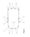
図2は、実施例の車両において車両周囲を認識するセンサ類の配置を示す模式図である。
ステレオカメラ71は、車両1の前部、後部、左右側部にそれぞれ設けられている。
レーザスキャナ81は、車両1の周囲に実質的に死角が生じないよう分布して複数設けられている
後側方レーダ91は、例えば、車両1の車体左右側部に配置され、検知範囲を車両後方側かつ車幅方向外側に向けて配置されている。FIG. 2 is a schematic view showing the arrangement of sensors for recognizing the surroundings of the vehicle in the vehicle of the embodiment.
The
A plurality of
ナビゲーション装置100は、例えばGPS受信機等の自車両位置測位手段、予め準備された地図データを蓄積したデータ蓄積手段、自車両の前後方向の方位を検出するジャイロセンサ等を有する。
地図データは、道路、交差点、インターチェンジ等の道路情報を車線レベルで有する。
道路情報は、3次元の車線形状データのほか、各車線(レーン)の右左折可否や、一時停止位置、制限速度等の走行上の制約となる情報も含む。
ナビゲーション装置100は、インストルメントパネルに組み込まれたディスプレイ101を有する。
ディスプレイ101は、ナビゲーション装置100がドライバに対して出力する各種情報が表示される画像表示装置である。
ディスプレイ101は、タッチパネルを有して構成され、ドライバからの各種操作入力が行われる入力部としても機能する。The
The map data has road information such as roads, intersections, and interchanges at the lane level.
The road information includes, in addition to three-dimensional lane shape data, information that becomes travel restrictions such as right / left turn availability of each lane (lane), temporary stop position, speed limit and the like.
The
The
The
路車間通信装置110は、所定の規格に準拠する通信システムによって、図示しない地上局と通信し、渋滞情報、交通信号機点灯状態、道路工事、事故現場、車線規制、天候、路面状況などに関する情報を取得するものである。 The road-to-
車車間通信装置120は、所定の規格に準拠する通信システムによって、図示しない他車両と通信し、他車両の位置、方位角、加速度、速度等の車両状態に関する情報や、車種、車両サイズ等の車両属性に関する情報を取得するものである。 The
画像生成ユニット200は、環境認識ユニット60から伝達される環境認識結果に基づいて、ディスプレイ210により表示される自車両周辺の環境に関する情報を含む画像(環境画像)を生成するものである。
画像生成ユニット200は、ディスプレイ210と協働して、本発明の表示装置を構成する。The
The
ディスプレイ210は、車両の乗員と対向して配置された画像表示装置である。
ディスプレイ210は、例えば、インストルメントパネル等の内装部材に組み込まれたLCDを有する。The
The
次に、実施例の表示装置における画像表示時の動作、及び、画面表示の例について説明する。
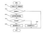
図3は、実施例の表示装置の動作を示すフローチャートである。
以下説明する動作は、車両1が例えば高速道路、自動車専用道などの高規格道路を、自動走行によって走行中に行われるものである。
以下、ステップ毎に順を追って説明する。Next, an operation at the time of image display in the display device of the embodiment and an example of screen display will be described.
FIG. 3 is a flowchart showing the operation of the display device of the embodiment.
The operation to be described below is performed while the
Hereinafter, each step will be described in order.
<ステップS01:目標走行ライン情報取得>
画像生成ユニット200は、自動運転制御ユニット50から現在自動運転制御において設定されている目標走行ラインに関する情報を取得する。
その後、ステップS02に進む。<Step S01: Target travel line information acquisition>
The
Thereafter, the process proceeds to step S02.
<ステップS02:曲線路有無判断>
画像生成ユニット200は、ステップS01において取得した情報に基づいて、自車両が近い将来(例えば所定の時間閾値以内)に曲線路を通過する予定であるか否かを判別する。
曲線路通過が予定される場合はステップS03に進み、その他の場合は一連の処理を終了(リターン)する。<Step S02: Curved Road Presence Determination>
The
If it is planned to pass the curved road, the process proceeds to step S03. Otherwise, the series of processes is ended (return).
<ステップS03:自車両周辺環境認識>
環境認識ユニット60は、ステレオカメラ71等を用いて、自車両周辺の環境に関する情報を取得する。
このとき、環境認識ユニット60は、ステップS02において検出された曲線路が存在する道路が、例えば合流路又は分岐路を有するインターチェンジ、ジャンクション、サービスエリア、パーキングエリア等を含む特定区間(第2の道路状況)であるか、このような特定区間以外の通常区間(第1の道路状況)であるかに関する情報を取得する。
特定区間は、通常区間に対して、比較的曲率が大きい曲線路(急カーブ)の出現可能性が高いことを考慮して設定されている。
その後、ステップS04に進む。<Step S03: Recognition of Surrounding Environment of Own Vehicle>
The
At this time, the
The specific section is set in consideration of the high possibility of occurrence of a curved road (a sharp curve) having a relatively large curvature with respect to the normal section.
Thereafter, the process proceeds to step S04.
<ステップS04:特定区間判断>
画像生成ユニット200は、環境認識ユニット60の認識結果に基づいて、自車両前方の曲線が通常区間に含まれるものか、特定区間に含まれるものかを判別する。
特定区間である場合はステップS06に進み、その他の場合はステップS05に進む。<Step S04: Specific Section Determination>
The
If it is a specific section, the process proceeds to step S06. Otherwise, the process proceeds to step S05.
<ステップS05:緩曲線表示出力>
画像生成ユニット200は、自車両及び自車両前方の道路形状(車線形状)を俯瞰した環境画像を生成する。
このような環境画像は、例えば、ディテールを省略して簡素化したコンピュータグラフィックスとして生成される。
画像生成ユニット200は、このような画像生成が可能なレンダリングエンジンを有する。
また、画像生成ユニット200は、環境画像の一部に重畳して、自車両前方に緩曲線が存在することを示す表示(緩曲線表示)を設ける。
画像生成ユニット200は、上述した画像をディスプレイ210に表示させ、一連の処理を終了(リターン)する。<Step S05: Slow Curve Display Output>
The
Such environment images are generated, for example, as simplified computer graphics by omitting details.
The
Further, the
The
<ステップS06:急曲線表示出力>
画像生成ユニット200は、ステップS05と実質的に同様の環境画像の一部に重畳して、自車両前方に急曲線が存在することを示す表示(急曲線表示)を設ける。
画像生成ユニット200は、上述した画像をディスプレイ210に表示させ、一連の処理を終了(リターン)する。<Step S06: Sudden Curve Display Output>
The
The
以下、実施例の表示装置における表示例について説明する。
図4は、実施例の表示装置における表示画像の一例を示す図である。
ディスプレイ210に表示される表示画像211は、自車両1、及び、道路Rの画像を含む。
道路Rは、右側車線LR、及び、左側車線LLの片側2車線を有する例えば高速道路等の高規格道路である。
自車両1は、左側車線LLに沿って走行している。
道路Rは、自車両1の前方において、比較的曲率の小さい穏やかな左カーブとなっている。
図4において、参考のため、自動運転制御において用いられる目標走行ラインL1を図示する。
実際には、ディスプレイ210には、目標走行ラインL1は表示されないようになっている。Hereinafter, display examples in the display device of the embodiment will be described.
FIG. 4 is a view showing an example of a display image in the display device of the embodiment.
The
The road R is a high standard road such as an expressway having two lanes on one side of the right lane LR and the left lane LL.
The
The road R has a gentle left curve with a relatively small curvature in front of the
In FIG. 4, a target travel line L1 used in automatic driving control is illustrated for reference.
In practice, the target travel line L1 is not displayed on the
図4に示す例においては、図3のステップS03において、通常区間(第1の道路状況)であると認識されることになる。
このため、表示画像211の一部には、緩曲線表示I1が設けられる。
緩曲線表示I1は、比較的穏やかに湾曲した矢印上の絵柄によって、左方向の緩曲線に沿って自車両1が走行することを示すものである。In the example shown in FIG. 4, in step S03 of FIG. 3, it will be recognized as a normal section (first road condition).
Therefore, a gentle curve display I1 is provided in part of the
The gentle curve display I1 indicates that the
図5は、実施例の表示装置における表示画像の他の例を示す図である。
図4と実質的に共通する箇所については同じ符号を付して説明を省略し、主に相違点について説明する。
図5においては、左側車線LLから左側へ分岐する分岐車線LDが設けられており、自車両1の目標走行ラインL2(これも実際には表示されない)は、分岐車線LDに流入し、分岐車線LDに沿って走行するよう設定されている。
分岐車線LDは、本線(車線LR,LL)よりも曲率が大きい左カーブとなっている。FIG. 5 is a view showing another example of the display image in the display device of the embodiment.
About the part which is substantially common with FIG. 4, the same code | symbol is attached | subjected, description is abbreviate | omitted, and a difference is mainly demonstrated.
In FIG. 5, a branch lane LD branched to the left side from the left lane LL is provided, and a target travel line L2 of the vehicle 1 (also not actually displayed) flows into the branch lane LD, and the branch lane It is set to travel along the LD.
The branch lane LD is a left curve having a curvature larger than that of the main line (lanes LR and LL).
図5に示す例においては、図3のステップS03において、通常区間に対して曲率が大きい曲線が存在する可能性が高い特定区間であると認識されることになる。
このため、表示画像211の一部には、急曲線表示I2が設けられる。
急曲線表示I2は、緩曲線表示I1よりも曲率が大きく湾曲した矢印上の絵柄によって、左方向の急曲線にそって自車両1が走行することを示すものである。In the example shown in FIG. 5, in step S03 of FIG. 3, it is recognized that the specific section is likely to be a specific section where there is a possibility that a curve having a large curvature is present.
For this reason, in part of the
The sharp curve display I2 indicates that the
以上説明したように、実施例の表示装置によれば、以下の効果を得ることができる。
(1)自車両1が今後通過する曲線の緩急を、道路状況に応じて2段階に表示することによって、乗員の監視負担を軽減しつつ、車両1が自車両前方の曲線路を正常に認識していることを示し、自動運転制御に対する信頼を維持することができる。
(2)曲線の緩急に加えて左右の方向を示すことにより、監視負担をほとんど増加させることなく、ユーザに自動運転制御が正常に機能していることをより確実に認識させることができる。
(3)合流、分岐等の有無に応じて道路状況を2段階に層別して曲線路の緩急の表示を切り替えることによって、簡単な構成により上述した効果を得ることができる。As described above, according to the display device of the embodiment, the following effects can be obtained.
(1) By displaying the speed of the curve through which the
(2) By showing the direction of right and left in addition to the slop of the curve, it is possible to more surely recognize that the automatic driving control is functioning normally, with hardly any increase in monitoring load.
(3) The above-described effect can be obtained with a simple configuration by layering the road condition into two stages according to the presence or absence of merging, branching, etc. and switching the display of the speed of the curved road.
(変形例)
本発明は、以上説明した実施例に限定されることなく、種々の変形や変更が可能であって、それらも本発明の技術的範囲内である。
(1)表示装置の構成や、車両の構成は、上述した実施例に限定されず適宜変更することが可能である。また、実施例において車両は乗用車であるが、本発明は貨物車等の商用車、トラック、バス、自動二輪車、その他各種特殊車両などにも適用することが可能である。
(2)実施例において、車両はエンジンを走行用動力源とするものであったが、本発明はこれに限らず、電動モータや、エンジンと電動モータとを組み合わせたハイブリッドシステムを走行用動力源として用いることも可能である。
(3)自車両周辺の環境認識を行うセンサの種類や配置は、上述した実施例には限定されず、適宜変更することが可能である。例えば、実施例におけるセンサ類と併用あるいは代用して、ミリ波レーザ、レーザレーダ、単眼カメラ、超音波ソナー等の各種センサを用いることが可能である。
(4)実施例においては、表示画像を俯瞰図(鳥瞰図)としているが、これに限らず、例えば平面図や、仮想ドライバ視点から見たドライバーズビューとすることも可能である。また、3D表示が可能なディスプレイを用いて、3D表示を行ってもよい。また、インストルメントパネルに設けたディスプレイによる表示に限らず、例えば、フロントガラスに像を投影するヘッドアップディスプレイによって表示してもよい。
(5)実施例においては、道路状況を例えば通常区間と特定区間との2段階に層別しているが、これに限らず3段階以上に層別し、対応する曲率を示す表示を行ってもよい。(Modification)
The present invention is not limited to the embodiments described above, and various modifications and changes are possible, which are also within the technical scope of the present invention.
(1) The configuration of the display device and the configuration of the vehicle are not limited to the above-described embodiment and can be changed as appropriate. In the embodiment, the vehicle is a passenger car, but the present invention can be applied to commercial vehicles such as freight cars, trucks, buses, motorcycles, and various special vehicles.
(2) In the embodiment, the vehicle uses the engine as a driving power source, but the present invention is not limited to this, and an electric motor or a hybrid system combining an engine and an electric motor as a driving power source It is also possible to use as.
(3) The type and arrangement of sensors for performing environment recognition around the host vehicle are not limited to the above-described embodiment, and can be changed as appropriate. For example, various sensors such as a millimeter wave laser, a laser radar, a monocular camera, and an ultrasonic sonar can be used in combination with or instead of the sensors in the embodiment.
(4) In the embodiment, the display image is an overhead view (bird's-eye view). However, the present invention is not limited to this. For example, a plan view or a driver's view viewed from a virtual driver viewpoint can be used. In addition, 3D display may be performed using a display capable of 3D display. Also, the display is not limited to the display provided on the instrument panel, and may be displayed by, for example, a head-up display that projects an image on a windshield.
(5) In the embodiment, the road condition is stratified into two stages of, for example, a normal section and a specific section. However, the present invention is not limited to this and may be stratified into three or more stages to display a corresponding curvature. .
1 車両 10 エンジン制御ユニット
20 トランスミッション制御ユニット 21 前後進切替アクチュエータ
22 レンジ検出センサ 30 挙動制御ユニット
31 ハイドロリックコントロールユニット(HCU)
32 車速センサ
40 電動パワーステアリング(EPS)制御ユニット
41 モータ 42 舵角センサ
50 自動運転制御ユニット 51 入出力装置
60 環境認識ユニット 70 カメラ制御ユニット
71 ステレオカメラ 80 レーザスキャナ制御ユニット
81 レーザスキャナ 90 後側方レーダ制御ユニット
91 後側方レーダ 100 ナビゲーション装置
101 ディスプレイ
110 路車間通信装置 120 車車間通信装置
200 画像生成ユニット 210 ディスプレイ
211 表示画像 R 道路
LR 右側走行車線 LL 左側走行車線
LD 分岐車線 I1 緩曲線表示
I2 急曲線表示 L1,L2 目標走行ライン1
32
Claims (3)
Translated fromJapanese前記環境認識手段の認識結果に基づいて自車両の目標走行ラインを設定する走行ライン設定手段と、
自車両が前記目標走行ラインに沿って走行するよう制御する自動運転制御手段と
を有する車両に設けられる表示装置であって、
前記目標走行ラインに含まれる曲線を検出する曲線検出手段と、
前記曲線が含まれる道路を、曲率が所定値以上である曲線が存在する可能性の大小に応じて、高規格道路の通常走行時に相当する第1の道路状況と、高規格道路における分岐箇所、合流箇所の少なくとも一方に相当する第2の道路状況とを層別する道路状況層別手段と、
前記曲線検出手段による前記曲線の検出に応じて前記道路状況層別手段により層別された前記第1の道路状況と前記第2の道路状況とにそれぞれ相当する曲率を示す表示を表示する表示手段と
を備えることを特徴とする表示装置。Environment recognition means for recognizing the environment ahead of the host vehicle;
Travel line setting means for setting a target travel line of the vehicle based on the recognition result of the environment recognition means;
And d) an automatic driving control means for controlling the own vehicle to travel along the target travel line.
Curve detection means for detecting a curve included in the target travel line;
The first road condition corresponding to the normal traveling of the high standard road and the branch point on the high standard road according to the magnitude of the possibility that the curve having the curvature is equal to or more than the predetermined value, Road condition stratification meansfor stratifyingthe second road condition corresponding to at least one of the merging points ;
Display for displaying a display indicating a curvature correspondingrespectively to the second road condition and another has been the first road condition layer more to the road condition stratification means in response to detection of the curve by the curve detecting means And a display device characterized by comprising:
前記環境認識手段の認識結果に基づいて自車両の目標走行ラインを設定する走行ライン設定手段と、 Travel line setting means for setting a target travel line of the vehicle based on the recognition result of the environment recognition means;
自車両が前記目標走行ラインに沿って走行するよう制御する自動運転制御手段と Automatic operation control means for controlling the host vehicle to travel along the target travel line;
を有する車両に設けられる表示装置であって、 A display device provided in a vehicle having
前記目標走行ラインに含まれる曲線を検出する曲線検出手段と、 Curve detection means for detecting a curve included in the target travel line;
前記曲線が含まれる道路を、曲率が所定値以上である曲線が存在する可能性の大小に応じて緩曲線及び急曲線を含む複数段階に層別する道路状況層別手段と、 Road condition stratification means for stratifying a road including the curve into a plurality of stages including a gentle curve and a sharp curve according to the possibility of the existence of a curve whose curvature is a predetermined value or more;
前記曲線検出手段による前記曲線の検出に応じて前記道路状況層別手段によって層別された前記緩曲線及び前記急曲線に相当する曲率を絵柄により示す表示を表示する表示手段と Display means for displaying a display showing the curve corresponding to the slow curve and the sharp curve stratified by the road condition stratification means in response to the detection of the curve by the curve detection means;
を備えることを特徴とする表示装置。 A display device comprising:
を特徴とする請求項1又は請求項2に記載の表示装置。
The display device according to claim 1or 2 , wherein the display means displays the direction of the curve together with the display indicating the curvature.
Priority Applications (4)
| Application Number | Priority Date | Filing Date | Title |
|---|---|---|---|
| JP2016085769AJP6542708B2 (en) | 2016-04-22 | 2016-04-22 | Display device |
| CN201710231703.9ACN107303850B (en) | 2016-04-22 | 2017-04-11 | Display device |
| US15/487,369US10414432B2 (en) | 2016-04-22 | 2017-04-13 | Vehicle display device |
| DE102017108173.9ADE102017108173A1 (en) | 2016-04-22 | 2017-04-18 | Vehicle display device |
Applications Claiming Priority (1)
| Application Number | Priority Date | Filing Date | Title |
|---|---|---|---|
| JP2016085769AJP6542708B2 (en) | 2016-04-22 | 2016-04-22 | Display device |
Publications (2)
| Publication Number | Publication Date |
|---|---|
| JP2017194396A JP2017194396A (en) | 2017-10-26 |
| JP6542708B2true JP6542708B2 (en) | 2019-07-10 |
Family
ID=60021089
Family Applications (1)
| Application Number | Title | Priority Date | Filing Date |
|---|---|---|---|
| JP2016085769AActiveJP6542708B2 (en) | 2016-04-22 | 2016-04-22 | Display device |
Country Status (4)
| Country | Link |
|---|---|
| US (1) | US10414432B2 (en) |
| JP (1) | JP6542708B2 (en) |
| CN (1) | CN107303850B (en) |
| DE (1) | DE102017108173A1 (en) |
Families Citing this family (13)
| Publication number | Priority date | Publication date | Assignee | Title |
|---|---|---|---|---|
| JP7027738B2 (en)* | 2017-09-06 | 2022-03-02 | 株式会社デンソー | Driving support device |
| US20190228246A1 (en)* | 2018-01-25 | 2019-07-25 | Futurewei Technologies, Inc. | Pickup Service Based on Recognition Between Vehicle and Passenger |
| JP7086798B2 (en)* | 2018-09-12 | 2022-06-20 | 本田技研工業株式会社 | Vehicle control devices, vehicle control methods, and programs |
| CN109263644B (en)* | 2018-09-28 | 2020-07-28 | 潍柴动力股份有限公司 | A target recognition method and device |
| JP6697522B2 (en)* | 2018-09-28 | 2020-05-20 | 株式会社Subaru | Marking line recognition device |
| JP7189008B2 (en)* | 2018-12-25 | 2022-12-13 | Whill株式会社 | Electric mobility, displays and programs |
| DE102019202580A1 (en) | 2019-02-26 | 2020-08-27 | Volkswagen Aktiengesellschaft | Method for operating a driver information system in an ego vehicle and driver information system |
| DE102019202576A1 (en) | 2019-02-26 | 2020-08-27 | Volkswagen Aktiengesellschaft | Method for operating a driver information system in an ego vehicle and driver information system |
| DE102019202591A1 (en)* | 2019-02-26 | 2020-08-27 | Volkswagen Aktiengesellschaft | Method for operating a driver information system in an ego vehicle and driver information system |
| DE102019202581B4 (en)* | 2019-02-26 | 2021-09-02 | Volkswagen Aktiengesellschaft | Method for operating a driver information system in an ego vehicle and driver information system |
| DE102019202586A1 (en) | 2019-02-26 | 2020-08-27 | Volkswagen Aktiengesellschaft | Method for operating a driver information system in an ego vehicle and driver information system |
| CN111959499B (en)* | 2019-05-20 | 2022-02-18 | 上海汽车集团股份有限公司 | Vehicle control method and device |
| JP7465643B2 (en)* | 2019-09-27 | 2024-04-11 | 株式会社Subaru | Self-driving vehicles |
Family Cites Families (16)
| Publication number | Priority date | Publication date | Assignee | Title |
|---|---|---|---|---|
| US5402120A (en)* | 1993-08-18 | 1995-03-28 | Zexel Corporation | Navigation system |
| JPH09189565A (en)* | 1996-01-11 | 1997-07-22 | Yazaki Corp | Vehicle navigation system |
| JP3619628B2 (en)* | 1996-12-19 | 2005-02-09 | 株式会社日立製作所 | Driving environment recognition device |
| JP3475123B2 (en)* | 1999-05-24 | 2003-12-08 | アイシン・エィ・ダブリュ株式会社 | Navigation device and storage medium |
| US7257447B2 (en)* | 2005-04-20 | 2007-08-14 | Cardiac Pacemakers, Inc. | Method and apparatus for indication-based programming of cardiac rhythm management devices |
| AU2007343390A1 (en)* | 2007-01-10 | 2008-07-17 | Tomtom International B.V. | Navigation device and method for displaying navigation information |
| US7774121B2 (en)* | 2007-07-31 | 2010-08-10 | Gm Global Technology Operations, Inc. | Curve speed control system with adaptive map preview time and driving mode selection |
| JP5177105B2 (en) | 2009-09-24 | 2013-04-03 | 株式会社デンソー | Driving support display device |
| US9275287B2 (en) | 2011-06-13 | 2016-03-01 | Honda Motor Co., Ltd. | Driving assistance device |
| EP2815817A4 (en)* | 2012-02-13 | 2015-11-18 | Jp Steel Plantech Co | Roller leveler and method for correcting sheet material |
| US8825258B2 (en)* | 2012-11-30 | 2014-09-02 | Google Inc. | Engaging and disengaging for autonomous driving |
| EP2827594A1 (en)* | 2013-07-17 | 2015-01-21 | Harman Becker Automotive Systems GmbH | Digital device, network and method for streaming audio or video data |
| JP6303403B2 (en)* | 2013-10-31 | 2018-04-04 | 日産自動車株式会社 | Vehicle travel guidance apparatus and method |
| KR101901962B1 (en)* | 2013-11-08 | 2018-11-07 | 한국전자통신연구원 | Apparatus and method for autonomous driving controll using navigation |
| US9243921B2 (en)* | 2014-02-18 | 2016-01-26 | Google Inc. | Intuitive preview of upcoming navigational instructions |
| JP2016085769A (en) | 2014-10-23 | 2016-05-19 | ソニー株式会社 | Information processing device, information processing method, program, and recording medium |
- 2016
- 2016-04-22JPJP2016085769Apatent/JP6542708B2/enactiveActive
- 2017
- 2017-04-11CNCN201710231703.9Apatent/CN107303850B/enactiveActive
- 2017-04-13USUS15/487,369patent/US10414432B2/enactiveActive
- 2017-04-18DEDE102017108173.9Apatent/DE102017108173A1/enactivePending
Also Published As
| Publication number | Publication date |
|---|---|
| JP2017194396A (en) | 2017-10-26 |
| CN107303850B (en) | 2022-04-01 |
| DE102017108173A1 (en) | 2017-10-26 |
| US20170305460A1 (en) | 2017-10-26 |
| CN107303850A (en) | 2017-10-31 |
| US10414432B2 (en) | 2019-09-17 |
Similar Documents
| Publication | Publication Date | Title |
|---|---|---|
| JP6542708B2 (en) | Display device | |
| JP6294905B2 (en) | Display device | |
| JP6383376B2 (en) | Peripheral risk display device | |
| JP6688655B2 (en) | Vehicle condition monitoring device | |
| JP6305456B2 (en) | Display device | |
| CN107264399B (en) | Vehicle periphery monitoring device | |
| JP7100421B2 (en) | Display device | |
| JP6773433B2 (en) | Peripheral risk display device | |
| JP6688656B2 (en) | Surrounding risk display device | |
| JP7434866B2 (en) | Vehicle travel control method and travel control device | |
| JP6633957B2 (en) | Peripheral risk display | |
| JP2023136206A (en) | Driving support devices, vehicles, driving support methods, and programs | |
| JP6757585B2 (en) | Display device | |
| JP6744744B2 (en) | Display device | |
| JP6757586B2 (en) | Abnormality notification device | |
| JP2020201734A (en) | Vehicle control device | |
| JP6964060B2 (en) | Vehicle control system | |
| JP6667346B2 (en) | Peripheral risk display | |
| JP2021142958A (en) | Vehicular control apparatus and side-mirrorless vehicle | |
| JP6667347B2 (en) | Display device | |
| JP2017182566A (en) | Peripheral risk display device | |
| JP2023164171A (en) | Drive assistance device | |
| CN116890823A (en) | Vehicle control device, vehicle, vehicle control method and storage medium | |
| JP2020152280A (en) | Vehicle control device |
Legal Events
| Date | Code | Title | Description |
|---|---|---|---|
| A977 | Report on retrieval | Free format text:JAPANESE INTERMEDIATE CODE: A971007 Effective date:20180308 | |
| A131 | Notification of reasons for refusal | Free format text:JAPANESE INTERMEDIATE CODE: A131 Effective date:20180313 | |
| A131 | Notification of reasons for refusal | Free format text:JAPANESE INTERMEDIATE CODE: A131 Effective date:20181016 | |
| A521 | Request for written amendment filed | Free format text:JAPANESE INTERMEDIATE CODE: A523 Effective date:20181213 | |
| TRDD | Decision of grant or rejection written | ||
| A01 | Written decision to grant a patent or to grant a registration (utility model) | Free format text:JAPANESE INTERMEDIATE CODE: A01 Effective date:20190520 | |
| A61 | First payment of annual fees (during grant procedure) | Free format text:JAPANESE INTERMEDIATE CODE: A61 Effective date:20190613 | |
| R150 | Certificate of patent or registration of utility model | Ref document number:6542708 Country of ref document:JP Free format text:JAPANESE INTERMEDIATE CODE: R150 | |
| R250 | Receipt of annual fees | Free format text:JAPANESE INTERMEDIATE CODE: R250 | |
| R250 | Receipt of annual fees | Free format text:JAPANESE INTERMEDIATE CODE: R250 | |
| R250 | Receipt of annual fees | Free format text:JAPANESE INTERMEDIATE CODE: R250 | |
| R250 | Receipt of annual fees | Free format text:JAPANESE INTERMEDIATE CODE: R250 |