JP6541163B2 - Crystal vibrating reed and crystal oscillator - Google Patents
Crystal vibrating reed and crystal oscillatorDownload PDFInfo
- Publication number
- JP6541163B2 JP6541163B2JP2018044749AJP2018044749AJP6541163B2JP 6541163 B2JP6541163 B2JP 6541163B2JP 2018044749 AJP2018044749 AJP 2018044749AJP 2018044749 AJP2018044749 AJP 2018044749AJP 6541163 B2JP6541163 B2JP 6541163B2
- Authority
- JP
- Japan
- Prior art keywords
- crystal vibrating
- quartz
- vibrating piece
- quartz crystal
- crystal
- Prior art date
- Legal status (The legal status is an assumption and is not a legal conclusion. Google has not performed a legal analysis and makes no representation as to the accuracy of the status listed.)
- Active
Links
Images


Landscapes
- Piezo-Electric Or Mechanical Vibrators, Or Delay Or Filter Circuits (AREA)
Description
Translated fromJapanese本発明は、水晶振動片、および水晶振動子に関する。 The present invention relates to a quartz crystal vibrating piece and a quartz oscillator.
ATカットにより形成される水晶振動片において、厚み滑り振動による振動エネルギーを振動片の中央部に閉じ込めるために、端部の厚みを小さくし、端部へと伝わる振動を減衰する構造が知られている(特許文献1参照)。 In a quartz crystal vibrating piece formed by AT cut, in order to confine vibration energy due to thickness-slip vibration in the central portion of the vibrating piece, a structure is known in which the thickness of the end is reduced and the vibration transmitted to the end is attenuated. (See Patent Document 1).
水晶振動片の端部の厚みを小さくするために、ウェットエッチングにより水晶振動片の端部に斜面を形成する。このとき、ATカット水晶振動片は結晶異方性を有しているため、ウェットエッチングにより形成される斜面は、特定の傾斜角度を有する自然結晶面となる。しかし、自然結晶面はある程度大きい傾斜角を有するため、水晶振動片の主面と自然結晶面である斜面との境界部において、十分な減衰が成されないままに伝わった振動が発振し、振動エネルギーを水晶振動片の中央部に十分に閉じ込めることが困難な場合があった。 In order to reduce the thickness of the end of the crystal vibrating reed, a slope is formed on the end of the crystal vibrating reed by wet etching. At this time, since the AT cut quartz crystal vibrating piece has crystal anisotropy, the slope formed by the wet etching becomes a natural crystal plane having a specific inclination angle. However, since the natural crystal plane has a large inclination angle, the vibration transmitted without sufficient attenuation is oscillated at the boundary between the main surface of the quartz crystal vibrating piece and the slope which is the natural crystal plane, and the vibration energy is In some cases, it is difficult to sufficiently confine the crystal to the central portion of the crystal vibrating piece.
本発明はかかる事情に考慮してなされたものであり、その目的は、ATカット水晶振動片において、自然結晶面の構造にかかわらず、振動エネルギーを水晶振動片の中央部に精度よく閉じ込めることができる水晶振動片を提供することである。また、その水晶振動片を用いた水晶振動子を提供することである。 The present invention has been made in consideration of the above circumstances, and an object thereof is that in the AT cut quartz crystal vibrating piece, regardless of the structure of the natural crystal plane, the vibration energy can be accurately confined in the central portion of the quartz crystal vibrating piece. It is possible to provide a crystal vibrating piece that can be used. Another object of the present invention is to provide a quartz oscillator using the quartz vibrating reed.
本発明の水晶振動片の一つの態様は、ATカットにより形成された水晶振動板を備える水晶振動片において、前記水晶振動板は、対向して設けられる一対の基面と、前記基面に対して交差する側面と、前記基面の中央部に一体に設けられた四角錐台状の凸部と、を有し、前記凸部は、主面と、前記主面に対する角度が自然結晶面よりも緩やかに形成された斜面と、を有する。
本発明の水晶振動片は、ATカットにより形成される水晶振動片において、対抗して設けられる一対の基面と、前記基面に対して交差する側面と、前記基面の中央部に設けられた四角錐台状の凸部と、を有し、前記凸部は、主面と、前記主面に対する角度が自然結晶面よりも緩やかに形成された斜面と、を有する。
前記凸部は、前記一対の基面にそれぞれ設けられていてもよい。
本発明の水晶振動片は、ATカットにより形成される水晶振動片において、対向して設けられる一対の主面と、前記主面に対して交差し、自然結晶面として形成される側面と、前記主面と前記側面とを接続し、前記主面に対して前記自然結晶面より小さな傾斜角で形成される斜面と、を有する。One aspect of the quartz crystal vibrating piece according to the present invention is a quartz crystal vibrating piece includinga quartz crystal vibrating plate formed by AT cutting, wherein the quartz crystal vibrating plate comprises a pair of base surfaces provided opposite to each other and the base surface Side surfaces that intersect with each other and a quadrangular pyramidal convex portion integrally provided at the central portion of the base surface, and the convex portion has a main surface and an angle with respect to the main surface that is larger than that of the natural crystal surface Also has a gently formed slope.
The quartz crystal vibrating piece according to the present invention, in the quartz crystal vibrating piece formed bythe AT cut, is provided at a pair of opposed base surfaces, a side surface intersecting with the base surface, and a central portion of the base surface. And a convex portion having a quadrangular pyramidal frustum shape, and the convex portion has a main surface and an inclined surface formed at a more moderate angle with respect to the main surface than a natural crystal surface.
The convex portions may be respectively provided on the pair of base surfaces.
A quartz crystal vibrating piece according to the present invention is a quartz crystal vibrating piece formed by AT cutting, comprising: a pair of main surfaces provided opposite to each other; a side surface intersecting with the main surface and being formed as a natural crystal surface; The main surface and the side surface are connected, and the main surface has an inclined surface formed at an inclination angle smaller than the natural crystal surface.
この構成によれば、主面と側面とを接続する斜面における、主面に対する傾斜角度は自然結晶面に比べて小さい。そのため、主面と斜面の境界部において振動が発振することを抑制でき、かつ端部に伝わる振動を減衰できる。したがって、振動エネルギーを水晶振動片の中央部に閉じ込める精度を向上できる。 According to this configuration, the inclination angle with respect to the main surface in the slope connecting the main surface and the side surface is smaller than that of the natural crystal surface. Therefore, it is possible to suppress the oscillation of the vibration at the boundary between the main surface and the slope and to damp the vibration transmitted to the end. Therefore, it is possible to improve the accuracy of confining vibrational energy in the central portion of the quartz crystal vibrating piece.
前記斜面は、少なくとも一方の前記主面における対向する2辺に対応する位置に形成されていてもよい。
この構成によれば、中央部から斜面が備えられた両端部に伝わる振動を減衰でき、振動エネルギーの閉じ込め精度を向上できる。The slopes may be formed at positions corresponding to two opposing sides of at least one of the main surfaces.
According to this configuration, the vibration transmitted from the central portion to both ends provided with the slope can be damped, and the confinement accuracy of the vibration energy can be improved.
前記側面は、X軸と交差する面であってもよい。
この構成によれば、屈曲振動の抑制効果が高い水晶振動片が得られる。The side surface may be a surface intersecting with the X axis.
According to this configuration, it is possible to obtain a quartz crystal vibrating piece having a high effect of suppressing bending vibration.
前記側面は、Z’軸と交差する面であってもよい。
この構成によれば、輪郭振動の抑制効果が高い水晶振動片が得られる。The side surface may be a surface intersecting the Z ′ axis.
According to this configuration, it is possible to obtain a quartz crystal vibrating piece having a high effect of suppressing contour vibration.
前記主面は四角形であり、前記斜面は、少なくとも一方の前記主面における4辺に対応する位置にそれぞれ形成されていてもよい。
この構成によれば、振動エネルギーの閉じ込め精度に優れた水晶振動片が得られる。The main surface may be a quadrangle, and the slopes may be formed at positions corresponding to four sides of at least one of the main surfaces.
According to this configuration, it is possible to obtain a crystal vibrating reed excellent in the accuracy of confinement of vibrational energy.
前記斜面は、一方側の前記主面と、他方側の前記主面と、の辺に対応する位置に形成されていてもよい。
この構成によれば、振動エネルギーの閉じ込め精度に優れた水晶振動片が得られる。The slope may be formed at a position corresponding to the side of the main surface on one side and the main surface on the other side.
According to this configuration, it is possible to obtain a crystal vibrating reed excellent in the accuracy of confinement of vibrational energy.
前記傾斜角度は、20°以下であってもよい。
この構成によれば、振動エネルギーの閉じ込め精度に優れた水晶振動片が得られる。The inclination angle may be 20 ° or less.
According to this configuration, it is possible to obtain a crystal vibrating reed excellent in the accuracy of confinement of vibrational energy.
前記斜面の中心線平均粗さが、0.2nm以上、10nm以下であってもよい。
この構成によれば、面粗度が低いため、水晶振動片のインピーダンスを低くできる。The center line average roughness of the slope may be 0.2 nm or more and 10 nm or less.
According to this configuration, since the surface roughness is low, the impedance of the quartz crystal vibrating piece can be lowered.
本発明の水晶振動子は、本発明の水晶振動片を備える。
この構成によれば、前述した水晶振動片を備えるため、同様に性能の優れた水晶振動子が得られる。The crystal unit of the present invention includes the crystal vibrating piece of the present invention.
According to this configuration, since the above-described quartz vibrating reed is provided, a quartz vibrator having excellent performance can be obtained as well.
本発明の水晶振動片の製造方法は、ATカットにより形成される水晶振動片の製造方法であって、ウエハの両面のうち少なくとも一方の面をドライエッチングする工程と、前記ドライエッチングされた面に、水晶振動片の外形パターンのマスクを形成する工程と、ウェットエッチングによって、前記ウエハの前記ドライエッチングされた面に、斜面を形成する工程と、前記マスクを除去する工程と、前記ウエハを前記外形パターンに沿って個片化する工程と、を有する。 The method of manufacturing a quartz crystal vibrating piece according to the present invention is a method of manufacturing a quartz crystal vibrating piece formed by AT cutting, comprising: dry etching at least one of two surfaces of the wafer; A step of forming a mask of the outer pattern of the quartz crystal vibrating piece, a step of forming a slope on the dry-etched surface of the wafer by wet etching, a step of removing the mask, the outer shape of the wafer And Separating along the pattern.
この方法によれば、ウエハの一面と他面とのうち少なくとも一方をドライエッチングした後に、水晶振動片の外形パターンのマスクを形成し、ウェットエッチングをすることにより、ウエハの面上に斜面を形成する。これにより、ドライエッチングされたウエハ表面には、自然結晶面の傾斜角度に依存せず、傾斜が緩やかな斜面が形成される。そのため、ウエハを外形パターンに沿って、個片化することによって、自然結晶面よりも緩やかな斜面を備えた水晶振動片を製造できる。 According to this method, after dry-etching at least one of the one surface and the other surface of the wafer, a mask of the outer pattern of the crystal vibrating piece is formed and wet etching is performed to form the slope on the surface of the wafer. Do. As a result, on the dry-etched wafer surface, an inclined surface having a gentle inclination is formed without depending on the inclination angle of the natural crystal plane. Therefore, by dividing the wafer along the outer pattern, it is possible to manufacture a quartz crystal vibrating piece having a slope that is gentler than the natural crystal plane.
前記個片化する工程において、ウェットエッチングにより、自然結晶面を形成してもよい。
この方法によれば、自然結晶面と、自然結晶面よりも緩やかな斜面と、を備えた水晶振動片が得られる。In the singulating step, a natural crystal plane may be formed by wet etching.
According to this method, it is possible to obtain a quartz crystal vibrating piece having a natural crystal face and a slope gentler than the natural crystal face.
本発明の水晶振動片によれば、端部に自然結晶面よりも傾斜角度が緩やかな傾斜面を備えるため、自然結晶面の構造にかかわらず、振動エネルギーを水晶振動片の中央部に精度よく閉じ込めることができる。 According to the quartz crystal vibrating piece of the present invention, since the end portion is provided with the inclined surface having a gentler inclination angle than the natural crystal surface, regardless of the structure of the natural crystalline surface, the vibration energy is precisely applied to the central portion of the quartz crystal vibrating piece It can be locked up.
以下、図面を参照しながら、本発明の実施形態に係る水晶振動片、水晶振動片の製造方法および水晶振動子について説明する。
なお、本発明の範囲は、以下の実施の形態に限定されるものではなく、本発明の技術的思想の範囲内で任意に変更可能である。また、以下の図面においては、各構成をわかりやすくするために、実際の構造と各構造における縮尺や数等を異ならせる場合がある。Hereinafter, with reference to the drawings, a quartz crystal vibrating piece, a method of manufacturing the quartz crystal vibrating piece, and a quartz vibrator according to an embodiment of the present invention will be described.
The scope of the present invention is not limited to the following embodiments, and can be arbitrarily changed within the scope of the technical idea of the present invention. Moreover, in the following drawings, in order to make each structure intelligible, a scale, the number, etc. in an actual structure and each structure may be varied.
[第1実施形態]
図1は、本実施形態の水晶振動子を示す、分解斜視図である。
本実施形態の水晶振動子1は、図1に示すように、ベース基板2とリッド基板3とで2層に積層された箱状に形成されており、内部のキャビティC内に水晶振動片4がマウントされている。
水晶振動片4は、水晶振動板10と、水晶振動板10の表裏主面上にそれぞれ形成された一対の電極膜20と、を備えている。First Embodiment
FIG. 1 is an exploded perspective view showing the crystal unit according to the present embodiment.
The crystal unit 1 according to the present embodiment is formed in a box shape in which the
The quartz-
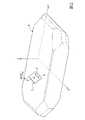
水晶振動板10は、図2に示すように、X軸、Y軸、Z軸で水晶結晶の座標軸が定義された水晶のランバード原石6をATカット(表裏主面がX軸回りにZ軸から半時計方向に約35度15分の角度となるようにカット)されることで得られた水晶板7を、その後、ウェットエッチング加工によって平面視矩形状に形成されたものである。
なお、図2は、水晶板7の切断角度及び水晶結晶の座標軸を説明するためのランバード原石6の斜視図である。また、本実施形態においてZ’軸とは、図1に示すように、水晶振動板10の表裏主面上においてX軸と直交する方向の結晶軸であり、Y’軸とはX軸およびZ’軸に対して直交する結晶軸をいう。As shown in FIG. 2, the
FIG. 2 is a perspective view of the Lambard ore 6 for explaining the cutting angle of the quartz plate 7 and the coordinate axis of the quartz crystal. Further, in the present embodiment, as shown in FIG. 1, the Z 'axis is a crystal axis in the direction orthogonal to the X axis on the front and back main surfaces of the
図3は、水晶振動片4を示す図であって、図3(a)は正面図、図3(b)は平面図、図3(c)は側面図である。
水晶振動板10は、図3に示すように、略直方体である。水晶振動板10における表主面10aの短辺方向(Z’軸方向)両端には、表主面10aと、自然結晶面である側面11bと、を接続するようにして斜面11aがそれぞれ形成されている。側面11bは、表裏主面10a,10bと略垂直であり、斜面11aは、表主面10aの長辺の全長に亘って表主面10aに対して角度θ1で傾斜している。FIG. 3 is a view showing the
The
斜面11aの角度θ1は、自然結晶面と水晶振動片の主面とが形成する角度の値よりも小さく、たとえば、20°以下である。斜面11aの寸法としては、たとえば、高さh1を5μmとした場合において、幅w1が50μm以上、200μm以下である。 The angle θ1 of the
一対の電極膜20は、図1および図3に示すように、それぞれ励振電極21と、引出電極22と、マウント電極23と、を備えている。
励振電極21は、水晶振動板10の表裏主面10a,10bの略中央部分にそれぞれ形成され、水晶振動板10を挟んで向かい合うように形成されている。また、水晶振動板10の長辺方向における一方側の端部(−X方向側)における、短辺方向(Z’軸方向)の両端部にはマウント電極23がそれぞれ設けられている。マウント電極23は、表主面10aから、斜面11aおよび側面11bを介して、裏主面10bに亘って形成されている。As shown in FIGS. 1 and 3, the pair of
The
また、マウント電極23のうち、一方のマウント電極23は引出電極22を介して表主面10a上に形成された一方の励振電極21に電気的に接続され、他方のマウント電極23は引出電極22を介して裏側の主面10b上に形成された他方の励振電極21に電気的に接続されている。
なお、上述した励振電極21、引出電極22およびマウント電極23からなる電極膜20は、金等の単層膜や、クロム等の金属を下地層とした上に金等の金属層を積層した積層膜で形成されている。Further, among the
The
このように構成された水晶振動片4は、バンプや導電性接着剤等の実装部材を利用して、図1に示すようにベース基板2の上面2aにマウントされる。より具体的には、ベース基板2の上面2aに形成されたインナー電極300に対して、水晶振動板10の裏主面10bに形成された一対のマウント電極23が実装部材を介してそれぞれ接触した状態でマウントされる。
これにより、水晶振動片4は、ベース基板2の上面2aに機械的に保持されると共に、インナー電極300とマウント電極23とがそれぞれ導通された状態となっている。The quartz
As a result, the quartz-
次に、図4から図6を参照して、水晶振動片4の製造方法について説明する。
図4は、水晶振動片4の製造工程を示すフローチャートである。
図5は、水晶振動片4の製造工程の手順を示す図であって、後述する凹部形成工程S2の手順を示す断面図および平面図である。
図6は、水晶振動片4の製造工程の手順を示す図であって、後述する個片化工程S3の手順を示す断面図および平面図である。Next, with reference to FIGS. 4 to 6, a method of manufacturing the quartz
FIG. 4 is a flowchart showing the manufacturing process of the
FIG. 5 is a view showing the procedure of the manufacturing process of the quartz
FIG. 6 is a diagram showing the procedure of the manufacturing process of the quartz
本実施形態の水晶振動片の製造方法は、図4に示すように、ウエハ準備工程S1と、凹部形成工程S2と、個片化工程S3と、電極形成工程S4と、を有する。
まず、図4に示すように、水晶のランバート原石をATカットして一定の厚みとしたウエハをラッピングして粗加工した後、加工変質層をエッチングで取り除き、この後、ポリッシュなどの鏡面研磨加工を行なって所定の厚みのウエハS(図5(a)参照)を準備する(S1)。As shown in FIG. 4, the method of manufacturing a quartz crystal vibrating piece of the present embodiment includes a wafer preparation step S1, a recess formation step S2, a singulation step S3, and an electrode formation step S4.
First, as shown in FIG. 4, after lumbering a Lambert ore of quartz and lapping a wafer with a certain thickness and roughing it, removing the damaged layer by etching, and thereafter mirror polishing such as polishing To prepare a wafer S having a predetermined thickness (see FIG. 5A) (S1).
凹部形成工程S2は、ウエハSの表面に後述する凹部42を形成する工程である。The recess forming step S2 is a step of forming a
まず、図5(a)に示すように、ウエハSの表面をドライエッチング加工する(S2a)。
ドライエッチングとしては、ウエハSの表面を、後述するウエハSを斜面エッチング加工する工程S2fにおいて、斜面11aが形成できる範囲内において、特に限定されない。たとえば、リアクティブイオンエッチング(RIE)や、逆スパッタ等を選択できる。
この工程により、ウエハSの表面が平坦化される。First, as shown in FIG. 5A, the surface of the wafer S is dry etched (S2a).
The dry etching is not particularly limited in the range in which the
By this process, the surface of the wafer S is planarized.
次に、図5(b)に示すように、ウエハSの両面にエッチング保護膜40とフォトレジスト膜41とをそれぞれ成膜する(S2b)。
エッチング保護膜40は、たとえば、クロム(Cr)を数10nm成膜したエッチング保護膜と、金(Au)を数10nm成膜したエッチング保護膜とが、順次積層された積層膜である。Next, as shown in FIG. 5B, the
The
この工程S2bにおいては、まず、ウエハSの表裏主面に、順次、エッチング保護膜40を、それぞれスパッタリング法や蒸着法などにより成膜する。
次いで、エッチング保護膜40上に、スピンコート法などによりレジスト材料を塗布して、フォトレジスト膜41を形成する。
なお、本実施形態で用いるレジスト材料としては、環化ゴム(たとえば、環化イソプレン)を主体にしたゴム系ネガレジストが好適に用いられている。ゴム系ネガレジストは、環化ゴムを有機溶剤に溶解し、さらにビスアジド感光剤を加えて、ろ過し、不純物を除去することで精製されたものである。In this step S2b, first, an
Next, a resist material is applied on the
In addition, as a resist material used by this embodiment, the rubber-type negative resist which mainly made cyclized rubber (for example, cyclized isoprene) is used suitably. The rubber-based negative resist is purified by dissolving a cyclized rubber in an organic solvent, adding a bisazide photosensitizer, and filtering it to remove impurities.
次に、エッチング保護膜40およびフォトレジスト膜41が成膜されたウエハSの一方側(+Y’方向側)の面を、外形パターンが形成されたフォトマスクを用いて一括で露光し、現像する。
これにより、図5(c)に示すように、フォトレジスト膜41の一方側に外形パターン41aを形成する(S2c)。
外形パターン41aは、水晶振動板10の外形に沿った形状である。Next, the surface on one side (the + Y ′ direction side) of the wafer S on which the etching
Thus, as shown in FIG. 5C, the
The
次に、外形パターン41aが形成されたフォトレジスト膜41をマスクとしてエッチング加工を行ない、マスクされていないエッチング保護膜40を選択的に除去する(S2d)。
次に、エッチング加工後にフォトレジスト膜41を剥離する(S2e)。
これらにより、図5(d)に示すように、エッチング保護膜40の一方側に外形パターン40aを形成する。Next, etching is performed using the
Next, the
As a result, as shown in FIG. 5D, the
なお、エッチング加工には、エッチング保護膜40とフォトレジスト膜41が形成されたウエハSを、薬液に浸漬して行うウェットエッチング方式を用いることができる。
具体的には、たとえば、エッチング保護膜40が、金(Au)からなる場合には、薬液としてヨウ素を用いてエッチングすることができる。
なお、このパターニングは、複数の水晶振動板10の数だけ、一括して行なう。In the etching process, a wet etching method can be used in which the wafer S on which the etching
Specifically, for example, when the
In addition, this patterning is collectively performed by the number of the plurality of
次に、エッチング保護膜40の外形パターン40aをマスクとして、マスクされていないウエハSを選択的に斜面エッチング加工する(S2f)。
これにより、図5(e)に示すように、マスクされていないウエハSの露出面から、マスクの下側の部分もエッチングされ、ウエハSの主面に対して緩やかな角度で交差する斜面11aを側面として有する凹部42が形成される。Next, using the
As a result, as shown in FIG. 5E, the portion under the mask is also etched from the exposed surface of the unmasked wafer S, and the
ここで、通常、水晶のエッチングでは、水晶特有のエッチング異方性によって、特定の角度を有する自然結晶面が現れる。またマスクされていない露出面から、マスクの下側(内側)にエッチングが進行することはほとんどみられない。
これに対して、本実施形態では、斜面エッチングを行う前に、ウエハSの表面をドライエッチング加工(S1)しているため、エッチングがマスクの下側にまで進行し、自然結晶面の角度に依存しない緩やかな角度を有する斜面を形成できる。Here, normally, in quartz etching, a natural crystal plane having a specific angle appears due to the etching anisotropy unique to quartz. In addition, it is hardly seen that the etching progresses from the unmasked exposed surface to the lower side (inner side) of the mask.
On the other hand, in the present embodiment, since the surface of the wafer S is dry-etched (S1) before slope etching, the etching proceeds to the lower side of the mask, and the angle of the natural crystal plane is It is possible to form a slope having a gentle angle which does not depend.
次に、図5(f)に示すように、エッチング保護膜40を除去するエッチング加工を行なう(S2g)。
以上の工程により、凹部形成工程S2が終了し、凹部42が形成されたウエハSが得られる。Next, as shown in FIG. 5F, an etching process is performed to remove the etching protection film 40 (S2g).
By the above steps, the recess forming step S2 is completed, and the wafer S in which the
個片化工程S3は、凹部42が形成されたウエハSを個片化し、水晶振動板10を形成する工程である。 The singulation step S3 is a step of singulating the wafer S in which the
まず、図6(a)に示すように、前述した成膜工程S2bと同様にして、ウエハSの両面にエッチング保護膜50およびフォトレジスト膜51を形成する(S3a)。 First, as shown in FIG. 6A, the
次に、エッチング保護膜50およびフォトレジスト膜51が成膜されたウエハSの一方側(+Y’方向側)の面を、外形パターンが形成されたフォトマスクを用いて一括で露光し、現像する。
これにより、図6(b)に示すように、フォトレジスト膜51の一方側に外形パターン51aを形成する(S3b)。
外形パターン51aは、水晶振動板10の外形に沿った形状である。Next, the surface on one side (the + Y ′ direction side) of the wafer S on which the etching
As a result, as shown in FIG. 6B, the
The
次に、外形パターン51aが形成されたフォトレジスト膜51をマスクとしてエッチング加工を行ない、マスクされていないエッチング保護膜50を選択的に除去する(S3c)。
次に、エッチング加工後にフォトレジスト膜51を剥離する(S3d)。
これらにより、図6(c)に示すように、エッチング保護膜50の一方側に外形パターン50aを形成する。Next, etching is performed using the
Next, the
As a result, as shown in FIG. 6C, the
次に、エッチング保護膜50の外形パターン50aをマスクとして、マスクされていないウエハSを選択的にエッチング加工する(S3e)。
これにより、図6(d)に示すように、自然結晶面である、水晶振動板10の側面11bが形成され、ウエハSは個片化される。
次に、図6(e)に示すように、エッチング保護膜50を除去するエッチング加工を行なう(S3f)。
以上の工程により、個片化工程S3が終了し、ウエハSが個片化された、水晶振動板10が製造される。Next, the unmasked wafer S is selectively etched using the
As a result, as shown in FIG. 6D, the
Next, as shown in FIG. 6E, etching is performed to remove the etching protection film 50 (S3f).
By the above-described steps, the singulation step S3 is completed, and the
電極形成工程S4は、水晶振動板10の表面上に電極を形成する工程である。この工程により、水晶振動板10の表面上に電極膜20が形成される。 The electrode forming step S4 is a step of forming an electrode on the surface of the
以上に述べたS1からS4までの工程により、水晶振動片4が製造される。 The
本実施形態の水晶振動片4によれば、斜面11aの表主面10aと成す角度θ1は、自然結晶面に比べて緩やかである。そのため、表主面10aと斜面11aとの境界部において振動が発振することを抑制でき、かつ水晶振動片4の端部に伝わる振動を十分に減衰できる。したがって、水晶振動片4の中央部に振動エネルギーを閉じ込める精度を向上できる。 According to the
また、水晶振動片においては、厚み滑り振動の他、屈曲振動、輪郭すべり振動等の振動モードがあることが知られている。これらの厚み滑り振動以外の振動(以下、不要振動という)の影響が大きいと、アクティビティディップが発生し、水晶振動片の振動特性が不安定になる。 In addition, in the quartz crystal vibrating piece, it is known that there are vibration modes such as bending vibration and contour slip vibration in addition to thickness slip vibration. If the influence of vibrations (hereinafter referred to as unnecessary vibrations) other than these thickness slip vibrations is large, activity dip occurs and the vibration characteristics of the quartz crystal vibrating piece become unstable.
厚み滑り振動が水晶振動片の厚さに依存するのに対して、不要振動の多くは水晶振動片の長さに依存するため、不要振動は水晶振動片の端部において発生しやすい。そのため、水晶振動片の中央部から端部に向けて水晶振動片の厚さを薄くし、端部での振動を減衰させることで、不要振動を抑制できる。水晶振動片の中央部から端部に向けて水晶振動片の厚さを薄くする方法としては、水晶振動片の端部に斜面を設ける方法があるが、従来の水晶振動片では、端部に設けられる斜面が水晶片の自然結晶面であったため、主面に対する角度が大きく、水晶振動片の端部ではなく、斜面と主面とが交差する位置において不要振動が発生してしまうという問題があった。 The thickness-slip vibration depends on the thickness of the quartz-crystal vibrating reed, whereas many unnecessary vibrations depend on the length of the quartz-crystal vibrating reed, so the unnecessary vibration is likely to occur at the end of the quartz-crystal vibrating reed. Therefore, unnecessary vibration can be suppressed by reducing the thickness of the crystal vibrating reed from the center portion to the end of the crystal vibrating reed and damping the vibration at the end. As a method of reducing the thickness of the quartz crystal vibrating piece from the center to the end of the quartz crystal vibrating piece, there is a method of providing an inclined surface at the end of the quartz crystal vibrating piece. Since the slope provided is the natural crystal face of the quartz piece, the angle to the main surface is large, and there is a problem that unnecessary vibration occurs at the intersection of the slope and the main surface, not at the end of the quartz vibrating piece. there were.
図7は、不要振動の発生に影響する寸法の違いを示した水晶振動片の正面図である。図7(a)は、従来の水晶振動片の一例である水晶振動片5を示しており、図7(b)は、本実施形態の水晶振動片4を示している。
図7(a)に示すように、従来の水晶振動片5では、表主面5aに対する斜面5cの角度θ2が自然結晶面の角度に依存するため、大きい(たとえば、30°、40°、50°)。そのため、不要振動が、両端部間の距離(短辺寸法)w4ではなく、斜面5cと表主面5aとが交差する線と、斜面5cと裏主面5bとが交差する線と、の幅方向(Z’軸方向)距離w2の長さに応じて発生しやすい。したがって、振動する部位の基準長さが短くなり、発生する不要振動の基本振動数が大きくなる。その結果、水晶振動片の厚み滑り振動と共に低次の不要振動が発生しやすくなり、不要振動による影響が大きくなっていた。FIG. 7 is a front view of a quartz-crystal vibrating piece showing differences in dimensions that affect the generation of unnecessary vibrations. FIG. 7A shows a quartz-
As shown in FIG. 7A, in the conventional quartz-
これに対して、本実施形態の水晶振動片4によれば、図7(b)に示すように、斜面11aの角度θ1が十分に緩やかに形成されているため(たとえば、20°以下)、斜面11aと表主面10aとが交差する位置において振動伝達が阻害されず、不要振動は端部において発生しやすい。そのため、振動する部位の基準寸法は、短辺寸法w3となり、前述した従来の水晶振動片5に比べて長くなる。これにより、発生する不要振動の基本振動数は低くなる。したがって、水晶振動片4と共に発生しやすい不要振動は高次の不要振動となり、不要振動による影響を低減できる。その結果、水晶振動片の振動特性を安定させることができる。 On the other hand, according to the
また、前述したように、水晶振動片4の端部における振動は十分に減衰されたものとなるため、端部において発生する不要振動の強度も小さくなる。したがって、不要振動が振動特性に与える影響を低減できる。 Further, as described above, the vibration at the end of the quartz-
また、本実施形態によれば、水晶振動片4の短辺方向(Z’軸方向)の両端部に設けられた斜面11aは、どちらも表主面10aに対して角度θ1で傾いている。そのため、振動のバランスがよくなり、厚みすべり主振動と、厚み副振動との周波数差を大きくできる。また、厚み副振動の振動強度も下げることができる。したがって、安定した振動が得られる。 Further, according to the present embodiment, the
また、本実施形態では、自然結晶面である側面11bは、Z’軸と交差する面である。
そのため、不要振動のうちの、特に屈曲振動に対して抑制効果が高い。Further, in the present embodiment, the
Therefore, among the unnecessary vibrations, in particular, the effect of suppressing bending vibration is high.
また、本実施形態の水晶振動片4の製造方法によれば、ウエハSをウェットエッチングによって加工する前に、加工する面にドライエッチング加工を行う。
前述したように、通常水晶結晶は、水晶特有のエッチング異方性によって、マスクされていない露出面に、特定の角度を有する自然結晶面が現れるという性質を有している。この自然結晶面における特定の角度は、水晶結晶のどの位置や面をエッチングするかによって決まる角度であり、たとえば、30°、40°、50°、90°等の値となる。Further, according to the method of manufacturing the quartz
As described above, normally, quartz crystal has a property that a natural crystal plane having a specific angle appears on an unmasked exposed surface due to etching anisotropy specific to quartz. The specific angle in the natural crystal plane is an angle determined by which position or plane of the quartz crystal is to be etched, and has a value of, for example, 30 °, 40 °, 50 °, 90 °.
これに対して、本実施形態によれば、ウエハSの主面にドライエッチング加工を施した後に、ウェットエッチングを行うと、ウエハのマスクされていない面から、マスクされた面側(マスクの内側)にエッチングが進み、上記のような自然結晶面の特定の角度に依存しない斜面を形成できる。 On the other hand, according to the present embodiment, when the main surface of the wafer S is subjected to the dry etching process and then the wet etching is performed, the masked side (the inner side of the mask from the unmasked surface of the wafer) Etching can be performed to form a slope which does not depend on the specific angle of the natural crystal plane as described above.
ウエハSの表面をドライエッチングすると、表面が平坦化されるとともに、極微小な突起がウエハSの表面上に形成される。詳しい原理は不明ではあるものの、このドライエッチングによって形成された微小突起により、その後に形成されるエッチング保護膜とウエハSの表面との間に微小な隙間が生じ、そこに、エッチング液が入り込むことによって、マスクの内側にエッチングが進行したのではないかと考えられる。 When the surface of the wafer S is dry-etched, the surface is planarized and minute projections are formed on the surface of the wafer S. Although the detailed principle is unclear, the microprotrusions formed by this dry etching cause micro gaps to be formed between the etching protective film formed later and the surface of the wafer S, and the etching solution penetrates there. It is considered that etching has progressed to the inside of the mask.
これにより、形成される自然結晶面の角度に依存しない斜面は、主面と成す角度が、自然結晶面における主面と成す角度に比べて緩やかな斜面となる。
したがって、本実施形態によれば、自然結晶面に比べて主面に対する傾き角度が緩やかな斜面を有する水晶振動片を製造することが可能であり、振動エネルギーの閉じ込め精度を向上できる。Thereby, the slope which does not depend on the angle of the natural crystal face to be formed is a slope that is gentler than the angle with the main face in the natural crystal face.
Therefore, according to the present embodiment, it is possible to manufacture a quartz crystal vibrating piece having an inclined surface whose inclination angle with respect to the main surface is gentler than that of a natural crystal surface, and it is possible to improve the confinement accuracy of vibration energy.
また、この方法により、形成される斜面11aの面粗度は低くなる。そのため、水晶振動片4のインピーダンスを低くできる。面粗度の値としては、たとえば、中心線平均粗さが、0.2nm以上、10nm以下である。 Further, according to this method, the surface roughness of the formed
[第1実施形態の変形例]
次に、水晶振動片の短辺方向をX軸、長辺方向をZ’軸とした第1実施形態の変形例について説明する。
図8は、第1実施形態の変形例の水晶振動片4Aを示した図であって、図8(a)は正面図、図8(b)は平面図、図8(c)は側面図である。
水晶振動片4Aは、図8に示すように、水晶振動板10Aと、水晶振動板10Aの表裏主面上にそれぞれ形成された一対の電極膜20と、を備えている。
水晶振動板10Aは、長辺側の側面に凸部60を備えている。凸部60は、X軸と交差する面に現れる自然結晶面によって形成される。Modified Example of First Embodiment
Next, a modified example of the first embodiment in which the short side direction of the quartz crystal vibrating piece is the X axis and the long side direction is the Z ′ axis will be described.
FIG. 8 is a view showing a
As shown in FIG. 8, the
The
本実施形態によれば、自然結晶面(凸部60)は、X軸と交差する面である。そのため、不要振動のうち、特に輪郭振動に対して抑制効果が高い。 According to the present embodiment, the natural crystal plane (convex portion 60) is a plane intersecting with the X axis. Therefore, among the unnecessary vibrations, the effect of suppressing the contour vibration is particularly high.
[第2実施形態]
次に、水晶振動片の短辺側に斜面が設けられた、第2実施形態ついて説明する。
図9は、第2実施形態の水晶振動片70を示した図であって、図9(a)は正面図、図9(b)は平面図、図9(c)は側面図である。
水晶振動片70は、図9に示すように、水晶振動板71と、水晶振動板71の表裏主面上にそれぞれ形成された一対の電極膜20と、を備えている。Second Embodiment
Next, a second embodiment in which a slope is provided on the short side of the crystal vibrating reed will be described.
FIG. 9 is a view showing the
As shown in FIG. 9, the quartz
水晶振動板71における、表裏主面71a,71bの短辺方向(X軸方向)に沿った側面72bは、自然結晶面であり、その全長に亘って表裏主面71a,71bに対して略直角な面とされている。
表主面71aの長辺方向(Z’軸方向)両端には、表主面71aの短辺の全長に亘って表主面71aに対して傾斜する斜面72aがそれぞれ形成されている。The
At both ends in the long side direction (Z ′ axis direction) of the front
本実施形態によれば、表主面71aの短辺に沿って、斜面72aが設けられているため、水晶振動片70の中央部から、長辺方向両側(±Z’方向側)に向かうにしたがって、振動が減衰する。そのため、マウント電極23が設けられている長辺方向一方側(−Z’方向側)の端部において、中央部から伝わる振動は十分に減衰されたものとなる。したがって、水晶振動片70が水晶振動子に実装された際に、マウント電極23が、実装部を介して、ベース基板上に形成されたインナー電極と接触することによる振動漏れを低減できる。 According to the present embodiment, since the
なお、本実施形態においては、長辺方向をZ’軸としたが、X軸としてもよい。その場合には、側面72bは、前述した第1実施形態の変形例に示した凸部60を形成するような斜面となる。 In the present embodiment, the long side direction is the Z 'axis, but may be the X axis. In that case, the
[第3実施形態]
次に、水晶振動片の短辺および長辺の4辺に斜面が設けられた、第3実施形態について説明する。
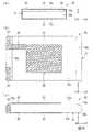
図10は、第3実施形態の水晶振動片100を示した図であって、図10(a)は正面図、図10(b)は平面図、図10(c)は側面図である。
本実施形態の水晶振動片100は、図10に示すように、水晶振動板101と、水晶振動板101の表裏主面上にそれぞれ形成された一対の電極膜20と、を備えている。Third Embodiment
Next, a third embodiment in which slopes are provided on four sides of the short side and the long side of the quartz crystal vibrating piece will be described.
FIG. 10 is a view showing the quartz
As shown in FIG. 10, the quartz
水晶振動板101における、表裏主面101a,101bの短辺方向(Z’軸方向)に沿った側面102bおよび長辺方向(X軸方向)に沿った側面103bは、その全長に亘って表裏主面101a,101bに対して略直角な面とされている。 The
表主面101aの短辺方向(Z’軸方向)両端には、表主面101aの長辺の全長に亘って表主面101aに対して傾斜する斜面103aがそれぞれ形成されている。
表主面101aの長辺方向(X軸方向)両端には、表主面101aの短辺の全長に亘って表主面101aに対して傾斜する斜面102aがそれぞれ形成されている。
斜面102a,103aの表裏主面101a,101bに対する傾斜角度は、自然結晶面よりも緩やかに形成されている。At both ends in the short side direction (Z ′ axis direction) of the front
At both ends in the long side direction (X-axis direction) of the front
The inclination angles of the
本実施形態によれば、長辺方向(X軸方向)および短辺方向(Z’軸方向)の両端それぞれに、自然結晶面よりも主面に対する傾斜角度が緩やかな斜面が形成されているため、長辺方向および短辺方向両方の端部における振動を十分減衰できる。したがって、水晶振動片の中央部に振動エネルギーを閉じ込める効果をより向上できる。 According to the present embodiment, slopes having a gentler inclination angle with respect to the main surface than the natural crystal surface are formed at both ends in the long side direction (X axis direction) and the short side direction (Z ′ axis direction). Vibration at both the long side direction and the short side direction can be sufficiently damped. Therefore, the effect of confining vibrational energy in the central portion of the quartz crystal vibrating piece can be further improved.
[第4実施形態]
次に、表裏主面両方の4辺にそれぞれ斜面が設けられた、第4実施形態について説明する。
図11は、第4実施形態の水晶振動片110を示した図であって、図11(a)は正面図、図11(b)は平面図、図11(c)は側面図である。
水晶振動片110は、図11に示すように、水晶振動板111と、水晶振動板111の表裏主面上にそれぞれ形成された一対の電極膜20と、を備えている。
水晶振動片110の裏主面101bの4辺には、前述した第3実施形態と同様に、斜面102a,103aが形成されている。Fourth Embodiment
Next, a fourth embodiment in which slopes are provided on the four sides of both the front and back main surfaces will be described.
FIG. 11 is a view showing the quartz
As shown in FIG. 11, the quartz
本実施形態によれば、水晶振動片の中央部に振動エネルギーを閉じ込める効果をより向上できる。 According to this embodiment, the effect of confining vibrational energy in the central portion of the quartz crystal vibrating piece can be further improved.
[第5実施形態]
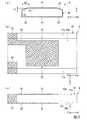
次に、メサ型の水晶振動片である、第5実施形態について説明する。
図12は、第5実施形態の水晶振動片120を示した図であって、図12(a)は正面図、図12(b)は平面図、図12(c)は側面図である。
水晶振動片120は、図12に示すように、水晶振動板121と、水晶振動板121の表裏主面上にそれぞれ形成された一対の電極膜20と、を備えている。Fifth Embodiment
Next, a fifth embodiment which is a mesa-type crystal vibrating piece will be described.
FIG. 12 is a view showing the quartz
As shown in FIG. 12, the quartz
水晶振動板121は、直方体200aと、直方体200aの基面124a,124bの中央部にそれぞれ設けられている四角錐台状の凸部200bと、で構成されている。
直方体200aの側面122b,123bは、基面124a,124bに対して略垂直に設けられている。
凸部200bは、面積の大きい側の面が、直方体200aの基面124a,124bとそれぞれ当接するようにして設けられており、反対側の面は、それぞれ水晶振動片120の表裏主面121a,121bとなっている。表裏主面121a,121b上には励振電極21が設けられており、表裏主面121a,121bは、直方体200aの基面124a,124bと平行である。The quartz
The side surfaces 122b and 123b of the
The
凸部200bにおける、短辺方向(Z’軸方向)に沿った斜面122aおよび長辺方向(X軸方向)に沿った斜面123aは、それぞれ表裏主面121a,121bに対する角度が、自然結晶面よりも緩やかに形成されている。 In the
[第6実施形態]
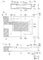
次に、逆メサ型の水晶振動片である、第6実施形態について説明する。
図13は、第6実施形態の水晶振動片130を示した図であって、図13(a)は正面図、図13(b)は平面図、図13(c)は側面図である。
水晶振動片130は、図13に示すように、水晶振動板131と、水晶振動板131の表裏主面上にそれぞれ形成された一対の電極膜20と、を備えている。Sixth Embodiment
Next, a sixth embodiment which is an inverted mesa type quartz crystal vibrating piece will be described.
FIG. 13 is a view showing a quartz-
The quartz
水晶振動板131は、直方体であり、基面134a,134bの中央部には、それぞれ凹部210が形成されている。水晶振動板131の側面132b,133bは、基面134a,134bに対して略垂直に設けられている。
凹部210は、側面が斜面となるように形成されている。凹部210の底面は、励振電極21が形成された表裏主面131a,131bであり、水晶振動板131の基面134a,134bと平行に形成されている。凹部210の長辺方向(X軸方向)に沿った側面である斜面133aおよび短辺方向(Z’軸方向)に沿った側面である斜面132aは、それぞれ表裏主面131a,131bに対する角度が、自然結晶面よりも緩やかに形成されている。The quartz-
The
1…水晶振動子、4,4A,70,100,110,120,130…水晶振動片、1
0a,71a,101a,121a,131a…表主面(主面)、10b,71b,10
1b,121b,131b…裏主面(主面)、11a,72a,102a,103a,1
22a,123a,132a,133a…斜面、11b,72b,102b,103b,
122b,123b,132b,133b…側面、40a…マスク、S…ウエハ1 ... crystal oscillator, 4, 4 A, 70, 100, 110, 120, 130 ... crystal vibrating piece, 1
0a, 71a, 101a, 121a, 131a ... main surface (main surface), 10b, 71b, 10
1b, 121b, 131b ... back main surface (main surface), 11a, 72a, 102a, 103a, 1
22a, 123a, 132a, 133a ... slopes, 11b, 72b, 102b, 103b,
122b, 123b, 132b, 133b ... side surface, 40a ... mask, S ... wafer
Claims (7)
Translated fromJapanese前記水晶振動板は、
対向して設けられる一対の基面と、
前記基面に対して交差する側面と、
前記基面の中央部に一体に設けられた四角錐台状の凸部と、
を有し、
前記凸部は、
主面と、
前記主面に対する角度が自然結晶面よりも緩やかに形成された斜面と、
を有する水晶振動片。Ina crystal vibrating reed provided with a crystal vibrating plate formed by AT cutting,
The quartz crystal plate is
A pair of base surfaces provided in pairstoward,
A side surface intersecting the base surface;
A quadrangular pyramidal convex portionintegrally provided at a central portion of the base surface;
Have
The convex portion is
Main surface,
A slope formed with an angle to the main surface more gently than a natural crystal surface;
Quartz crystal vibrating piece.
Priority Applications (1)
| Application Number | Priority Date | Filing Date | Title |
|---|---|---|---|
| JP2018044749AJP6541163B2 (en) | 2018-03-12 | 2018-03-12 | Crystal vibrating reed and crystal oscillator |
Applications Claiming Priority (1)
| Application Number | Priority Date | Filing Date | Title |
|---|---|---|---|
| JP2018044749AJP6541163B2 (en) | 2018-03-12 | 2018-03-12 | Crystal vibrating reed and crystal oscillator |
Related Parent Applications (1)
| Application Number | Title | Priority Date | Filing Date |
|---|---|---|---|
| JP2013052138ADivisionJP6350784B2 (en) | 2013-03-14 | 2013-03-14 | Method for manufacturing quartz vibrating piece |
Publications (2)
| Publication Number | Publication Date |
|---|---|
| JP2018093544A JP2018093544A (en) | 2018-06-14 |
| JP6541163B2true JP6541163B2 (en) | 2019-07-10 |
Family
ID=62565757
Family Applications (1)
| Application Number | Title | Priority Date | Filing Date |
|---|---|---|---|
| JP2018044749AActiveJP6541163B2 (en) | 2018-03-12 | 2018-03-12 | Crystal vibrating reed and crystal oscillator |
Country Status (1)
| Country | Link |
|---|---|
| JP (1) | JP6541163B2 (en) |
Family Cites Families (8)
| Publication number | Priority date | Publication date | Assignee | Title |
|---|---|---|---|---|
| JPS53148794A (en)* | 1977-06-01 | 1978-12-25 | Seiko Instr & Electronics Ltd | Method of processing thick sliding oscillators |
| JP4665282B2 (en)* | 2000-02-18 | 2011-04-06 | エプソントヨコム株式会社 | AT cut crystal unit |
| JP5234236B2 (en)* | 2001-04-12 | 2013-07-10 | セイコーエプソン株式会社 | Quartz substrate and method for manufacturing quartz substrate |
| JP4305542B2 (en)* | 2006-08-09 | 2009-07-29 | エプソントヨコム株式会社 | AT cut quartz crystal resonator element and manufacturing method thereof |
| JP2008263387A (en)* | 2007-04-11 | 2008-10-30 | Epson Toyocom Corp | Mesa-type piezoelectric vibrating piece |
| JP5507298B2 (en)* | 2010-03-12 | 2014-05-28 | エスアイアイ・クリスタルテクノロジー株式会社 | Method for manufacturing quartz diaphragm |
| JP2012199606A (en)* | 2011-03-18 | 2012-10-18 | Nippon Dempa Kogyo Co Ltd | Crystal vibration piece and crystal device |
| JP2013070228A (en)* | 2011-09-22 | 2013-04-18 | Nippon Dempa Kogyo Co Ltd | Crystal oscillator |
- 2018
- 2018-03-12JPJP2018044749Apatent/JP6541163B2/enactiveActive
Also Published As
| Publication number | Publication date |
|---|---|
| JP2018093544A (en) | 2018-06-14 |
Similar Documents
| Publication | Publication Date | Title |
|---|---|---|
| JP6350784B2 (en) | Method for manufacturing quartz vibrating piece | |
| KR100880984B1 (en) | AT cut quartz crystal vibrating piece and its manufacturing method | |
| JP6344677B2 (en) | Crystal resonator element and crystal unit | |
| TWI669838B (en) | Crystal oscillator | |
| US8987974B2 (en) | Piezoelectric device and method for manufacturing the same | |
| TWI591868B (en) | Piezoelectric quartz wafer with double convex structure and processing method thereof | |
| US20130241358A1 (en) | Quartz crystal device and method for fabricating the same | |
| TW201711234A (en) | Crystal oscillator | |
| JP6541163B2 (en) | Crystal vibrating reed and crystal oscillator | |
| JP6410117B2 (en) | Method for manufacturing quartz vibrating piece | |
| US5304459A (en) | At-cut crystal oscillating reed and method of etching the same | |
| TWI788716B (en) | Piezoelectric device and manufacturing method of the same | |
| TWI652839B (en) | Piezoelectric quartz wafer with single convex structure | |
| JP2019193066A (en) | Crystal oscillator | |
| JP5719056B1 (en) | Piezoelectric vibrating piece, piezoelectric vibrator, and method of manufacturing piezoelectric vibrating piece | |
| CN107431474B (en) | AT-cut crystal piece and crystal oscillator | |
| JP2012105074A (en) | Piezoelectric substrate, method of manufacturing the same, and method of manufacturing piezoelectric vibrating reed | |
| JP5234236B2 (en) | Quartz substrate and method for manufacturing quartz substrate | |
| JP6386298B2 (en) | Manufacturing method of crystal element | |
| JP5908630B2 (en) | Piezoelectric vibrating piece, piezoelectric vibrator, and method of manufacturing piezoelectric vibrating piece | |
| JP7694218B2 (en) | Manufacturing method of vibration element | |
| KR101606962B1 (en) | Quartz vibrator and manufactering method thereof | |
| JP7423231B2 (en) | Manufacturing method of piezoelectric vibrating piece, piezoelectric vibrating piece and piezoelectric vibrator | |
| US20230155564A1 (en) | Method for Manufacturing Vibration Element | |
| JP5908629B2 (en) | Piezoelectric vibrating piece, piezoelectric vibrator, and method of manufacturing piezoelectric vibrating piece |
Legal Events
| Date | Code | Title | Description |
|---|---|---|---|
| A621 | Written request for application examination | Free format text:JAPANESE INTERMEDIATE CODE: A621 Effective date:20180312 | |
| A977 | Report on retrieval | Free format text:JAPANESE INTERMEDIATE CODE: A971007 Effective date:20190131 | |
| A131 | Notification of reasons for refusal | Free format text:JAPANESE INTERMEDIATE CODE: A131 Effective date:20190205 | |
| A521 | Request for written amendment filed | Free format text:JAPANESE INTERMEDIATE CODE: A523 Effective date:20190401 | |
| TRDD | Decision of grant or rejection written | ||
| A01 | Written decision to grant a patent or to grant a registration (utility model) | Free format text:JAPANESE INTERMEDIATE CODE: A01 Effective date:20190514 | |
| A61 | First payment of annual fees (during grant procedure) | Free format text:JAPANESE INTERMEDIATE CODE: A61 Effective date:20190605 | |
| R150 | Certificate of patent or registration of utility model | Ref document number:6541163 Country of ref document:JP Free format text:JAPANESE INTERMEDIATE CODE: R150 | |
| R250 | Receipt of annual fees | Free format text:JAPANESE INTERMEDIATE CODE: R250 | |
| R250 | Receipt of annual fees | Free format text:JAPANESE INTERMEDIATE CODE: R250 | |
| R250 | Receipt of annual fees | Free format text:JAPANESE INTERMEDIATE CODE: R250 | |
| R250 | Receipt of annual fees | Free format text:JAPANESE INTERMEDIATE CODE: R250 |