JP6539812B1 - Inspection method of lens - Google Patents
Inspection method of lensDownload PDFInfo
- Publication number
- JP6539812B1 JP6539812B1JP2018135101AJP2018135101AJP6539812B1JP 6539812 B1JP6539812 B1JP 6539812B1JP 2018135101 AJP2018135101 AJP 2018135101AJP 2018135101 AJP2018135101 AJP 2018135101AJP 6539812 B1JP6539812 B1JP 6539812B1
- Authority
- JP
- Japan
- Prior art keywords
- lens
- image
- correction
- inspection
- pattern
- Prior art date
- Legal status (The legal status is an assumption and is not a legal conclusion. Google has not performed a legal analysis and makes no representation as to the accuracy of the status listed.)
- Active
Links
Images


Classifications
- G—PHYSICS
- G01—MEASURING; TESTING
- G01N—INVESTIGATING OR ANALYSING MATERIALS BY DETERMINING THEIR CHEMICAL OR PHYSICAL PROPERTIES
- G01N21/00—Investigating or analysing materials by the use of optical means, i.e. using sub-millimetre waves, infrared, visible or ultraviolet light
- G01N21/84—Systems specially adapted for particular applications
- G01N21/88—Investigating the presence of flaws or contamination
- G01N21/95—Investigating the presence of flaws or contamination characterised by the material or shape of the object to be examined
- G01N21/958—Inspecting transparent materials or objects, e.g. windscreens
- G—PHYSICS
- G01—MEASURING; TESTING
- G01M—TESTING STATIC OR DYNAMIC BALANCE OF MACHINES OR STRUCTURES; TESTING OF STRUCTURES OR APPARATUS, NOT OTHERWISE PROVIDED FOR
- G01M11/00—Testing of optical apparatus; Testing structures by optical methods not otherwise provided for
- G01M11/02—Testing optical properties
- G01M11/0242—Testing optical properties by measuring geometrical properties or aberrations
- G01M11/025—Testing optical properties by measuring geometrical properties or aberrations by determining the shape of the object to be tested
- G—PHYSICS
- G01—MEASURING; TESTING
- G01N—INVESTIGATING OR ANALYSING MATERIALS BY DETERMINING THEIR CHEMICAL OR PHYSICAL PROPERTIES
- G01N21/00—Investigating or analysing materials by the use of optical means, i.e. using sub-millimetre waves, infrared, visible or ultraviolet light
- G01N21/84—Systems specially adapted for particular applications
- G01N21/88—Investigating the presence of flaws or contamination
- G01N21/95—Investigating the presence of flaws or contamination characterised by the material or shape of the object to be examined
- G01N21/958—Inspecting transparent materials or objects, e.g. windscreens
- G01N2021/9583—Lenses
Landscapes
- Physics & Mathematics (AREA)
- Geometry (AREA)
- Chemical & Material Sciences (AREA)
- Analytical Chemistry (AREA)
- General Physics & Mathematics (AREA)
- Health & Medical Sciences (AREA)
- Life Sciences & Earth Sciences (AREA)
- Biochemistry (AREA)
- General Health & Medical Sciences (AREA)
- Immunology (AREA)
- Pathology (AREA)
- Testing Of Optical Devices Or Fibers (AREA)
- Investigating Materials By The Use Of Optical Means Adapted For Particular Applications (AREA)
Abstract
Translated fromJapaneseDescription
Translated fromJapanese本発明は、撮像装置によって取得した画像を使用するレンズの検査方法に関する。 The present invention relates to a lens inspection method using an image acquired by an imaging device.
撮像装置によって取得した画像を使用するレンズの検査方法が開発されている(たとえば、特許文献1)。 A lens inspection method using an image acquired by an imaging device has been developed (e.g., Patent Document 1).
しかし、従来の画像を使用するレンズの検査方法によって、脈理(密度や成分のゆらぎなどによる屈折率の異常)などの欠陥を検出することは困難であり、脈理などの欠陥を実用上、十分な精度で検出することのできる画像を使用するレンズの検査方法は開発されていなかった。 However, it is difficult to detect defects such as striae (abnormality of refractive index due to fluctuations in density or component) by a conventional inspection method of lenses using images, and defects such as striae are practically No inspection method has been developed for lenses that use images that can be detected with sufficient accuracy.
したがって、脈理などの欠陥を実用上、十分な精度で検出することのできる画像を使用するレンズの検査方法に対するニーズがある。本発明の課題は、脈理などの欠陥を実用上、十分な精度で検出することのできる画像を使用するレンズの検査方法を提供することである。 Therefore, there is a need for a method of inspecting a lens using an image that can detect defects such as striae with sufficient accuracy for practical use. An object of the present invention is to provide a lens inspection method using an image that can detect defects such as cords with sufficient accuracy for practical use.
本発明によるレンズの検査方法は、検査対象レンズを通して縞パターンの画像を採取するステップと、該画像の歪曲を補正するステップと、該縞パターンを空間的なキャリア信号として、フーリエ縞解析法によって位相変化の情報を取り出し、該位相変化の情報を使用して該検査対象レンズの欠陥箇所を検出するステップと、を含む。 The inspection method of a lens according to the present invention comprises the steps of: collecting an image of a fringe pattern through a lens to be inspected; correcting distortion of the image; and using the fringe pattern as a spatial carrier signal by Fourier fringe analysis. Taking out change information, and using the phase change information to detect a defect in the inspection target lens.
本発明によれば、フーリエ縞解析法によって取り出した位相変化の情報を使用して該検査対象レンズの欠陥箇所を検出するので、脈理などの欠陥を実用上、十分な精度で検出することができる。 According to the present invention, since the defect location of the lens to be inspected is detected using the information on the phase change extracted by the Fourier fringe analysis method, defects such as striae can be detected with sufficient accuracy for practical use. it can.
本発明に第1の実施形態によるレンズの検査方法においては、縞パターンの画像を採取するステップにおいて、検査対象レンズと補正レンズとの組合せを通して画像を採取する。 In the lens inspection method according to the first embodiment of the present invention, in the step of collecting an image of a fringe pattern, an image is acquired through a combination of a lens to be inspected and a correction lens.
本実施形態によれば、補正レンズによって歪曲がある程度補正されるので、画像における歪曲の補正が容易になり、フーリエ縞解析法を適用する際に有利である。 According to this embodiment, the distortion is corrected to some extent by the correction lens, so that the distortion in the image can be easily corrected, which is advantageous when applying the Fourier fringe analysis method.
本発明に第2の実施形態によるレンズの検査方法においては、該縞パターンの周期を、検出対象の想定される欠陥の最小の大きさよりも小さくなるように定めている。 In the lens inspection method according to the second embodiment of the present invention, the period of the fringe pattern is set to be smaller than the minimum size of the assumed defect to be detected.
本実施形態によれば、欠陥に対して縞パターンの周期を適切に定めることにより、確実に欠陥を検出することが可能となる。 According to this embodiment, it is possible to reliably detect a defect by appropriately determining the period of the fringe pattern with respect to the defect.
本発明に第3の実施形態によるレンズの検査方法においては、該縞パターンの周期が、該画像において少なくとも2以上の画素に対応するように定めている。 In the lens inspection method according to the third embodiment of the present invention, the period of the fringe pattern is determined to correspond to at least two or more pixels in the image.
本実施形態によれば、縞パターンの周期に対応する画素数を適切に定めることにより、確実に欠陥を検出することが可能となる。縞パターンの周期に対応する画素数が2未満であると縞パターンのコントラストが著しく低下する。縞パターンの周期に対応する画素数は、3乃至10に定めるのがより好ましい。縞パターンの周期に対応する画素数が3以上であるとコントラストがより向上する。縞パターンの周期に対応する画素数が10を超えるとカメラの解像度が過剰となりコストが過大となる。 According to the present embodiment, it is possible to reliably detect a defect by appropriately determining the number of pixels corresponding to the period of the fringe pattern. If the number of pixels corresponding to the period of the fringe pattern is less than 2, the contrast of the fringe pattern is significantly reduced. The number of pixels corresponding to the period of the fringe pattern is more preferably set to 3 to 10. When the number of pixels corresponding to the period of the stripe pattern is 3 or more, the contrast is further improved. When the number of pixels corresponding to the period of the stripe pattern exceeds 10, the resolution of the camera becomes excessive and the cost becomes excessive.
本発明に第4の実施形態によるレンズの検査方法においては、該検査対象レンズが円筒状レンズであり、該円筒の部分の長手方向と該縞パターンの縞の長手方向とが垂直となるような状態で該縞パターンの画像を採取する。 In the lens inspection method according to the fourth embodiment of the present invention, the inspection target lens is a cylindrical lens, and the longitudinal direction of the portion of the cylinder and the longitudinal direction of the stripes of the stripe pattern are perpendicular. An image of the fringe pattern is taken in the state.
本実施形態においては、検査対象の円筒状レンズの円筒の部分の長手方向と縞パターンの縞の長手方向とが垂直となるような状態で縞パターンの画像を採取するので、円筒状レンズによる縞パターンの縞の歪曲が生じにくい。したがって、画像における歪曲の補正が容易になり、フーリエ縞解析法を適用する際に有利である。 In the present embodiment, since the image of the stripe pattern is taken in a state in which the longitudinal direction of the cylindrical portion of the cylindrical lens to be inspected and the longitudinal direction of the stripe of the stripe pattern are perpendicular, the stripe by the cylindrical lens It is hard to produce distortion of the stripe of a pattern. Therefore, correction of distortion in the image is facilitated, which is advantageous when applying Fourier fringe analysis.
本発明に第5の実施形態によるレンズの検査方法においては、該検査対象レンズがその表面上において線状に延びた部分であって、該線に垂直な断面の形状がほぼ一定であり、周囲の部分と比較して空間周波数の高い部分を備え、該線の長手方向と該縞パターンの縞の長手方向とが垂直となるような状態で該縞パターンの画像を採取する。 In the lens inspection method according to the fifth embodiment of the present invention, the inspection target lens is a linearly extending portion on the surface, and the shape of the cross section perpendicular to the line is substantially constant, An image of the stripe pattern is acquired in a state where the longitudinal direction of the line and the longitudinal direction of the stripe of the stripe pattern are perpendicular to each other, with a portion of high spatial frequency compared to the portion of.
本実施形態においては、表面上において線状に延びた部分であって、該線に垂直な断面の形状がほぼ一定であり、周囲の部分と比較して空間周波数の高い部分を備えたレンズを検査する際に、該線の長手方向と該縞パターンの縞の長手方向とが垂直となるような状態で該縞パターンの画像を採取するので、該部分による縞パターンの縞の歪曲が生じにくい。したがって、画像における歪曲の補正が容易になり、フーリエ縞解析法を適用する際に有利である。レンズの表面上において線状に延びた部分であって、該線に垂直な断面の形状がほぼ一定であり、周囲の部分と比較して空間周波数の高い部分は、一例として、車両用灯具のレンズの出射面において水平方向に延在するシリンドリカル状の凸条部又は凹条部であり、鉛直方向に複数並んで配置されるフルートカットである。 In this embodiment, a lens having a linearly extending portion on the surface, which has a substantially constant cross-sectional shape perpendicular to the line, and a portion having a high spatial frequency as compared to the surrounding portion is obtained. At the time of inspection, since the image of the stripe pattern is taken such that the longitudinal direction of the line and the longitudinal direction of the stripe of the stripe pattern are perpendicular, distortion of the stripe pattern due to the portion is less likely to occur. . Therefore, correction of distortion in the image is facilitated, which is advantageous when applying Fourier fringe analysis. A linearly extending portion on the surface of the lens, the shape of the cross section perpendicular to the line being substantially constant, and the portion having a high spatial frequency compared to the surrounding portion is, for example, a vehicle lamp It is a cylindrical ridge or recess extending in the horizontal direction on the light exit surface of the lens, and is a flute cut arranged in plural in the vertical direction.
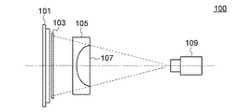
図1は、本発明のレンズの欠陥の検査方法を実施するために使用される撮像光学系100を示す図である。撮像光学系100は、照明装置101と、表面に縞パターンが形成された板103と、補正レンズ(ヌルレンズ)105と、検査対象レンズ107と、撮像装置109と、を含む。補正レンズ105は検査対象レンズ107による画像の歪曲を補正する目的で使用される。補正レンズ105、検査対象レンズ107、及び撮像装置109は、これらの中心が板103の縞パターンが形成された表面に垂直な直線上に位置するように配置される。上記の直線を光軸と呼称し、図1において一点鎖線で示す。撮像光学系100は、板103の縞パターンの光軸に垂直な方向の画像を、補正レンズ105と検査対象レンズ107との組合せを通して採取するように構成されている。なお、補正レンズ105及び検査対象レンズ107は逆向きに、すなわち検査対象レンズ107の凸の面が撮像装置109に向くように配置してもよい。 FIG. 1 is a view showing an imaging
表面に縞パターンが形成された板103は、ロンキー・ルーリングであってもよい。ロンキー・ルーリングは、無色透明のフロートガラス基板上全面に平行線のパターンが施されたもので、平行線の線幅と線の間の空間の幅とは等しい。一例として、ロンキー・ルーリングの縞パターンは、1インチに100組の線と線の間の空間との組合せである。この場合、1インチは、2.54ミリメータであるので、線幅と線の間の空間の幅の和、すなわち縞の周期は25.4マイクロメータであり、線幅と線の間の空間の幅とはともに12.7マイクロメータである。 The
補正レンズ105の形状は、検査対象レンズ107による画像の歪曲を補正するように定める。補正レンズ105の形状の定め方については後で説明する。 The shape of the
ここで、撮像装置109の仕様の決め方について説明する。まず、撮像装置109の視野を決める。視野は板103の大きさよりも少し大きめとする。つぎに、撮像装置109の視野の大きさと撮像装置109のセンサのサイズから撮像装置109のレンズの倍率を決める。この倍率及びセンサの画素数から、センサの1画素に対応する検査対称の部分のサイズが求まる。一般的に、検査対象の欠陥の最小サイズが約10画素以上となるような画素数のセンサを選択する。 Here, how to decide the specification of the
実際に使用した撮像装置109の画素数は500万画素である。セルサイズ(画素サイズ)は、3.45μm×3.45μmであり、レンズの倍率は1である。ロンキー・ルーリングの線幅は約3.7画素に相当し、ロンキー・ルーリングの周期は約7.4画素に相当する。この場合に、10画素は約35マイクロメータに相当する。 The number of pixels of the
一般的に、縞の周期、すなわちロンキー・ルーリングの周期は、検査対象の欠陥の最小サイズよりも小さくするように定める。また、縞の周期が少なくとも2以上の画素に対応するように画素数を定める。縞パターンの周期に対応する画素数が2未満であると縞パターンのコントラストが著しく低下する。縞パターンの周期に対応する画素数は、3乃至10に定めるのがより好ましい。縞パターンの周期に対応する画素数が3以上であるとコントラストがより向上する。縞パターンの周期に対応する画素数が10を超えるとカメラの解像度が過剰となりコストが過大となる。 Generally, the period of fringes, ie, the period of Ronchi-ruling, is determined to be smaller than the minimum size of the defect to be inspected. Further, the number of pixels is determined so that the period of the stripes corresponds to at least two or more pixels. If the number of pixels corresponding to the period of the fringe pattern is less than 2, the contrast of the fringe pattern is significantly reduced. The number of pixels corresponding to the period of the fringe pattern is more preferably set to 3 to 10. When the number of pixels corresponding to the period of the stripe pattern is 3 or more, the contrast is further improved. When the number of pixels corresponding to the period of the stripe pattern exceeds 10, the resolution of the camera becomes excessive and the cost becomes excessive.
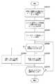
図2は、本発明のレンズの欠陥の検査方法を説明するための流れ図である。 FIG. 2 is a flow chart for explaining the inspection method of the lens defect of the present invention.
図2のステップS1010において、検査対象レンズと補正レンズとの組合せを通して縞パターンの画像を採取する。補正レンズによって画像の歪曲を完全に補正することはできないので、検査対象レンズと補正レンズとの組合せを通して撮像した画像はなお歪曲している。なお、検査対象レンズの屈折力が小さな場合には、補正レンズを使用せずに検査レンズのみを通して縞パターンの画像を採取してもよい。 In step S1010 of FIG. 2, an image of a fringe pattern is acquired through the combination of the inspection target lens and the correction lens. Since the correction lens can not completely correct the distortion of the image, the image taken through the combination of the inspection object lens and the correction lens is still distorted. If the refractive power of the inspection target lens is small, the image of the stripe pattern may be collected only through the inspection lens without using the correction lens.
図2のステップS1020において、画像の歪曲を補正する。一般に、画像の歪曲を補正する補正プログラムを利用することができる(たとえば、OpenCVライブラリなど)。このような補正プログラムは、画像において、補正前の位置にある輝度情報を補正後の位置に移動して画像を再構成する。すなわち、画像の補正前の位置及び補正後の位置を入力として補正プログラムに与えれば、画像の歪曲を補正することができる。 In step S1020 of FIG. 2, distortion of the image is corrected. In general, correction programs can be used to correct image distortion (eg, OpenCV library, etc.). Such a correction program reconstructs an image by moving luminance information at a position before correction to the position after correction in the image. That is, the distortion of the image can be corrected if the position before the correction of the image and the position after the correction are input to the correction program.
図3は、画像の補正前の位置及び補正後の位置を求める方法を説明するための流れ図である。 FIG. 3 is a flow chart for explaining a method of obtaining the position before correction and the position after correction of the image.
図3のステップS2010において、検査対象レンズによる歪曲をできるだけ補正する補正レンズを設計する。補正レンズを設計する際には、一例として、一辺が所定の長さの正方格子のチャートを、検査対象レンズと補正レンズとの組合せを通して撮像した画像を、光線追跡法による光学シミュレーションによって求め、該画像における正方格子の歪曲の状態を観察しながら画像の歪曲をできるだけ小さくするように補正レンズの形状を修正しながら設計する。 In step S2010 of FIG. 3, a correction lens is designed to correct as much as possible distortion caused by the inspection target lens. When designing a correction lens, as an example, an image obtained by imaging a chart of a square lattice having a predetermined length on one side through a combination of a lens to be inspected and a correction lens is obtained by optical simulation by a ray tracing method. It is designed while correcting the shape of the correction lens so as to minimize distortion of the image while observing the distortion state of the square lattice in the image.
図3のステップS2020において、一例として、一辺が所定の長さの正方格子のチャートを、検査対象レンズと上記のように設計された補正レンズとの組合せを通して撮像した画像を、光学シミュレーションによって求める。 In step S2020 of FIG. 3, as one example, an image obtained by capturing a chart of a square lattice having a predetermined length on one side through a combination of the inspection object lens and the correction lens designed as described above is obtained by optical simulation.
図4は、検査対象レンズと補正レンズとの組合せを通して撮像した正方格子の画像を示す図である。図4の点線は、検査対象レンズと補正レンズとの組合せを通して撮像した正方格子の歪曲した画像を示す。図4の実線は、正方格子の歪曲を補正した形状を示す。 FIG. 4 is a view showing an image of a square lattice taken through a combination of a lens to be inspected and a correction lens. The dotted line in FIG. 4 shows a distorted image of a square grid taken through the combination of the lens under test and the correction lens. The solid line in FIG. 4 shows the shape of square grid distortion corrected.
図3のステップS2030において、図4において点線で示される歪曲した正方格子の格子点、及び図4において実線で示される正方格子の格子点を、それぞれ画像の補正前の位置、及び補正後の位置とする。上述のように、このようにして求めた画像の補正前の位置及び補正後の位置を入力として補正プログラムに与えることによって、画像の歪曲を補正することができる。 In step S2030 in FIG. 3, the grid points of the distorted square grid shown by dotted lines in FIG. 4 and the grid points of the square grid shown by solid lines in FIG. 4 are the positions before and after correction of the image, respectively. I assume. As described above, the distortion of the image can be corrected by giving the position before correction and the position after correction of the image thus obtained to the correction program as an input.
図2のステップS1030において、縞パターンを空間的なキャリア信号として、フーリエ縞解析法によって位相変化の情報を取り出し、該位相変化の情報を使用して該検査対象レンズの欠陥箇所を検出する。 In step S1030 in FIG. 2, information on phase change is extracted by Fourier fringe analysis using the fringe pattern as a spatial carrier signal, and the information on the phase change is used to detect a defect in the inspection target lens.
図5は、図2のステップS1030において縞パターンを空間的なキャリア信号として実施されるフーリエ縞解析法を説明するための流れ図である。実際には、2次元の画像処理を実施するが、図5においては、簡単のために、1次元の画像処理として説明する。 FIG. 5 is a flow chart for explaining a Fourier fringe analysis method implemented using the fringe pattern as a spatial carrier signal in step S1030 of FIG. In practice, two-dimensional image processing is carried out, but in FIG. 5 it will be described as one-dimensional image processing for the sake of simplicity.
なお、フーリエ縞解析法の詳細は、Mitsuo Takeda et al., “Fourier-transform method of fringe-pattern analysis for computer-based topography and interferometry”, J. Opt. Soc. Am./Vol. 72, No. 1/January 1982に記載されている。また、国立大学法人電気通信大学のサイト(https://www.uec.ac.jp/research/information/column/09.html)にフーリエ縞解析法の解説が記載されている。以下の、図5のステップS3010−S3030の説明は、上記のサイトの説明の一部を引用して行う。 The details of the Fourier fringe analysis method are described in Mitsuo Takeda et al., “Fourier-transform method of fringe-pattern analysis for computer-based topography and interferometry”, J. Opt. Soc. Am./Vol. 72, No. It is described in 1 / January 1982. In addition, an explanation of the Fourier fringe analysis method is described on the National University Corporation University of Electro-Communications site (https://www.uec.ac.jp/research/information/column/09.html). The following description of steps S3010 to S3030 in FIG. 5 will be made by citing a part of the above description of the site.
図5のステップS3010において、採取した画像の光の強度分布g(x)をフーリエ変換してG(f)を得る。 In step S3010 of FIG. 5, the light intensity distribution g (x) of the collected image is subjected to Fourier transform to obtain G (f).
ここで、g(x)は以下の式で表現される。
g(x)のフーリエ変換は、
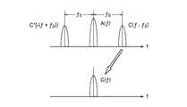
図6は、式(4)を模式的に表した図である。 FIG. 6 is a diagram schematically showing the formula (4).
図5のステップS3020において、G(f)の、空間キャリア周波数f0近傍の成分であるC(f−f0)を求める。In step S3020 in FIG. 5, C (f−f0 ) which is a component of G (f) near the space carrier frequency f0 is determined.
図5のステップS3030において、C(f−f0)を原点に移動させてC(f)を求め、C(f)をフーリエ逆変換してc(x)を得る。ここで、C(f−f0)を原点に移動させる作業は、空間キャリア周波数を取り除くことに相当する。In step S3030 in FIG. 5, C (f−f0 ) is moved to the origin to obtain C (f), and C (f) is subjected to inverse Fourier transform to obtain c (x). Here, the operation of moving C (f−f0 ) to the origin corresponds to removing the space carrier frequency.
図5のステップS3040において、位置xにおけるc(x)が所定値よりも大きいか否か判断する。検査対象レンズの形状や屈折率などの物理量が周囲と比較して変化した場合には位相φ(X)が変化するので、c(x)が大きくなると考えられる。したがって、位置xにおけるc(x)が所定値よりも大きいか否か判断することによって、位置xにおいて欠陥が存在するか否か判断することができる。上記の所定値は、複数の欠陥のないレンズのc(x)の平均値を求め、その値に所定の係数、たとえば、1.2または1.5などを乗ずることによって求める。位置xにおけるc(x)が所定値よりも大きければ、ステップS3050に進む。位置xにおけるc(x)が所定値以下であれば、ステップS3060に進む。 In step S3040 in FIG. 5, it is determined whether c (x) at position x is larger than a predetermined value. When the physical quantity such as the shape and refractive index of the lens to be inspected changes as compared with the surroundings, the phase φ (X) changes, so it is considered that c (x) becomes large. Therefore, by determining whether c (x) at position x is larger than a predetermined value, it can be determined whether a defect exists at position x. The above predetermined value is obtained by calculating the average value of c (x) of a plurality of non-defective lenses and multiplying the value by a predetermined coefficient, for example, 1.2 or 1.5. If c (x) at position x is larger than a predetermined value, the process proceeds to step S3050. If c (x) at the position x is equal to or less than a predetermined value, the process advances to step S3060.
図5のステップS3050において、位置xにおいて欠陥が存在すると判断する。 In step S3050 of FIG. 5, it is determined that a defect exists at position x.
図5のステップS3060において、位置xにおいて欠陥が存在しないと判断する。 In step S3060 of FIG. 5, it is determined that no defect exists at position x.
図5のステップS3070において、全てのxについての処理が終了したか否か判断する。全てのxについての処理が終了していれば全体の処理を終了する。全てのxについての処理が終了していなければ、他のxについての処理を実施するようにステップS3040に戻る。 In step S3070 in FIG. 5, it is determined whether the processing for all x has ended. If the processing for all x is complete, the entire processing is terminated. If the process for all x has not been completed, the process returns to step S3040 so as to perform the process for another x.
実際には、2次元の光の強度分布g(x、y)に対して、図5の流れ図に示した処理を実施する。2次元の光の強度分布g(x、y)の2次元離散フーリエ変換の式は以下のとおりである。
また、C(u,v)の2次元離散フーリエ逆変換の式は以下のとおりである。
上述のように縞パターンを空間的なキャリア信号として実施されるフーリエ縞解析法によれば、検査対象レンズの形状や屈折率などの物理量の変化をc(x,y)の大きさの変化として検出することができる。 According to the Fourier fringe analysis method in which the fringe pattern is implemented as a spatial carrier signal as described above, changes in physical quantities such as the shape and refractive index of the lens to be inspected are changes in the magnitude of c (x, y) It can be detected.
上述のように、縞パターンの空間周波数、すなわち縞の周期は、検出したい最小の欠陥のサイズ以下である必要がある。たとえば、上述のように、縞の周期が25.4マイクロメータであれば、検出し得る欠陥のサイズは25.4マイクロメータよりも大きい。 As mentioned above, the spatial frequency of the fringe pattern, i.e. the fringe period, needs to be less than or equal to the size of the smallest defect to be detected. For example, as described above, if the fringe period is 25.4 micrometers, then the size of defects that can be detected is larger than 25.4 micrometers.
ここで、縞パターンの縞の方向とレンズの向きとの関係について検討する。上述のように補正レンズ、及び図3のステップS2010の処理によって画像の歪曲は補正される。しかし、画像の歪曲を完全に補正することはできない。フーリエ縞解析法においては、採取された画像の縞のパターンができるだけ歪曲されていないことが望ましい。 Here, the relationship between the direction of the stripes of the stripe pattern and the direction of the lens will be examined. As described above, the distortion of the image is corrected by the correction lens and the process of step S2010 in FIG. However, the distortion of the image can not be completely corrected. In Fourier fringe analysis, it is desirable that the fringe pattern of the acquired image not be as distorted as possible.
図7は、シリンドリカルレンズ107Aと補正レンズ105Aとを組み合わせたものの光軸を含む断面を示す図である。図7において、縞パターンの縞がシリンドリカルレンズ107Aの長手方向と平行となるように配置されている。補正レンズ105A及びシリンドリカルレンズ107Aを通して採取した画像の歪曲を完全に補正することはできないので、画像における縞パターンは歪曲する。 FIG. 7 is a view showing a cross section including an optical axis of a combination of the
図8は、シリンドリカルレンズ107Aと補正レンズ105Aとを組み合わせたものの光軸を含む断面を示す図である。図8において、縞パターンの縞がシリンドリカルレンズ107Aの長手方向と垂直となるように配置されている。画像における縞パターンは長手方向に伸縮するが歪曲はしない。 FIG. 8 is a view showing a cross section including the optical axis of the combination of the
したがって、検査対象レンズがシリンドリカルレンズである場合には、縞パターンの縞がシリンドリカルレンズの長手方向と垂直となるように配置するのが望ましい。 Therefore, when the lens to be inspected is a cylindrical lens, it is desirable to arrange the stripes of the stripe pattern so as to be perpendicular to the longitudinal direction of the cylindrical lens.
また、車両用灯具のレンズでは、カットオフライン近傍に照射される光の一部を拡散させるように、レンズの出射面にフルートカットと呼ばれる部分を設けることがある。フルートカットは、水平方向に延在するシリンドリカル状の凸条部又は凹条部であり、鉛直方向に複数並んで配置される。フルートカットはシリンドリカル状であるので、検査対象レンズがこのようなフルートカットを備えたレンズである場合には、検査対象レンズがシリンドリカルレンズである場合と同じ理由により縞パターンの縞がフルートカットの延伸方向と垂直となるように配置するのが望ましい。 In addition, in the lens of the vehicle lamp, a part called a flute cut may be provided on the exit surface of the lens so as to diffuse a part of the light irradiated in the vicinity of the cutoff line. The flute cut is a cylindrical ridge or recess extending in the horizontal direction, and a plurality of flute cuts are arranged in the vertical direction. Since the flute cut has a cylindrical shape, when the inspection target lens is a lens provided with such a flute cut, the stripes of the stripe pattern are extended by the flute cut for the same reason as the case where the inspection target lens is a cylindrical lens. It is desirable to arrange so as to be perpendicular to the direction.
Claims (5)
Translated fromJapanese該光学シミュレーションによって、該検査対象レンズと該補正レンズとの組合せを通して得た補正用画像を求めるステップと、
該補正用画像を使用して歪曲の補正プログラムを調整するステップと、
該検査対象レンズと該補正レンズとの組合せを通して縞パターンの検査用画像を採取するステップと、
調整された該補正プログラムを使用して該検査用画像の歪曲を補正するステップと、
該縞パターンを空間的なキャリア信号として、フーリエ縞解析法によって位相変化の情報を取り出し、該位相変化の情報を使用して該検査対象レンズの欠陥箇所を検出するステップと、を含むレンズの検査方法。Designing a correction lens that corrects distortion due to the inspection target lens by optical simulation;
Obtaining an image for correction obtained through a combination of the inspection target lens and the correction lens by the optical simulation;
And adjusting the distortion correction program usingthe correction image,
Obtaining an inspection image of a fringe pattern through a combination of the inspection target lens and the correction lens;
Correcting distortion of the inspection image using the adjusted correction program;
Retrieving information on phase change by Fourier fringe analysis using the fringe pattern as a spatial carrier signal, and using the information on the phase change to detect a defect in the inspection object lens. Method.
Priority Applications (2)
| Application Number | Priority Date | Filing Date | Title |
|---|---|---|---|
| JP2018135101AJP6539812B1 (en) | 2018-07-18 | 2018-07-18 | Inspection method of lens |
| CN201910608712.4ACN110736756B (en) | 2018-07-18 | 2019-07-08 | Lens inspection method |
Applications Claiming Priority (1)
| Application Number | Priority Date | Filing Date | Title |
|---|---|---|---|
| JP2018135101AJP6539812B1 (en) | 2018-07-18 | 2018-07-18 | Inspection method of lens |
Publications (2)
| Publication Number | Publication Date |
|---|---|
| JP6539812B1true JP6539812B1 (en) | 2019-07-10 |
| JP2020012731A JP2020012731A (en) | 2020-01-23 |
Family
ID=67212079
Family Applications (1)
| Application Number | Title | Priority Date | Filing Date |
|---|---|---|---|
| JP2018135101AActiveJP6539812B1 (en) | 2018-07-18 | 2018-07-18 | Inspection method of lens |
Country Status (2)
| Country | Link |
|---|---|
| JP (1) | JP6539812B1 (en) |
| CN (1) | CN110736756B (en) |
Cited By (1)
| Publication number | Priority date | Publication date | Assignee | Title |
|---|---|---|---|---|
| WO2022162953A1 (en)* | 2021-02-01 | 2022-08-04 | リーダー電子株式会社 | Resolution measurement method, resolution measurement system, and program |
Families Citing this family (1)
| Publication number | Priority date | Publication date | Assignee | Title |
|---|---|---|---|---|
| JP2023054520A (en)* | 2021-10-04 | 2023-04-14 | 日本電気硝子株式会社 | Manufacturing method for transparent body |
Family Cites Families (14)
| Publication number | Priority date | Publication date | Assignee | Title |
|---|---|---|---|---|
| JPS5139869B2 (en)* | 1973-04-18 | 1976-10-30 | ||
| US3981562A (en)* | 1974-09-09 | 1976-09-21 | Optical Coating Laboratory, Inc. | Spatial filtering for error detection |
| JP3417738B2 (en)* | 1995-09-06 | 2003-06-16 | ペンタックス株式会社 | Optical member inspection device |
| JP3613906B2 (en)* | 1996-09-20 | 2005-01-26 | 株式会社ニコン | Wavefront aberration measuring device |
| US6201600B1 (en)* | 1997-12-19 | 2001-03-13 | Northrop Grumman Corporation | Method and apparatus for the automatic inspection of optically transmissive objects having a lens portion |
| JP2002202112A (en)* | 2000-11-06 | 2002-07-19 | Fujitsu Ltd | Shape measuring device |
| US6771362B2 (en)* | 2001-12-27 | 2004-08-03 | Rotlex Ltd. | Method and apparatus for testing and mapping phase objects |
| FR2897426B1 (en)* | 2006-02-16 | 2012-07-27 | Onera (Off Nat Aerospatiale) | WAVE SURFACE ANALYSIS METHOD BY MULTILATERAL INTERFEROMETRY WITH FREQUENCY DIFFERENCE |
| JP2008076223A (en)* | 2006-09-21 | 2008-04-03 | Matsushita Electric Ind Co Ltd | Cylindrical transparent body inspection method and inspection apparatus used therefor |
| EP2063260A1 (en)* | 2007-11-19 | 2009-05-27 | Lambda-X | Fourier transform deflectometry system and method |
| JP2008135745A (en)* | 2007-11-22 | 2008-06-12 | Nikon Corp | Wavefront aberration measuring machine and projection exposure apparatus |
| JP4685971B2 (en)* | 2009-09-24 | 2011-05-18 | 株式会社ケー・デー・イー | Inspection system and inspection method |
| JP6487617B2 (en)* | 2013-09-12 | 2019-03-20 | 株式会社クラレ | Defect inspection method and defect inspection apparatus for microlens array |
| CN106707448B (en)* | 2016-11-28 | 2020-09-04 | 歌尔科技有限公司 | Adjusting system and adjusting method for lens assembly and display module |
- 2018
- 2018-07-18JPJP2018135101Apatent/JP6539812B1/enactiveActive
- 2019
- 2019-07-08CNCN201910608712.4Apatent/CN110736756B/enactiveActive
Cited By (4)
| Publication number | Priority date | Publication date | Assignee | Title |
|---|---|---|---|---|
| WO2022162953A1 (en)* | 2021-02-01 | 2022-08-04 | リーダー電子株式会社 | Resolution measurement method, resolution measurement system, and program |
| JP2022117666A (en)* | 2021-02-01 | 2022-08-12 | リーダー電子株式会社 | RESOLUTION MEASUREMENT METHOD, RESOLUTION MEASUREMENT SYSTEM AND PROGRAM |
| JP7304641B2 (en) | 2021-02-01 | 2023-07-07 | リーダー電子株式会社 | Chart generation method, resolution measurement method, resolution measurement system, and program |
| TWI858231B (en)* | 2021-02-01 | 2024-10-11 | 日商利達電子股份有限公司 | Resolution measurement method, resolution measurement system, computer device and computer readable medium |
Also Published As
| Publication number | Publication date |
|---|---|
| CN110736756A (en) | 2020-01-31 |
| JP2020012731A (en) | 2020-01-23 |
| CN110736756B (en) | 2023-10-03 |
Similar Documents
| Publication | Publication Date | Title |
|---|---|---|
| CN104160241B (en) | Phase distribution analysis method, device and program of fringe image using high-dimensional luminance information | |
| TWI436051B (en) | A pattern inspection apparatus, a pattern inspection method, and a recording medium in which a program is recorded | |
| DE102017200628B4 (en) | Sample testing device | |
| JP2015045635A (en) | Wavefront measuring method, shape measuring method, optical element manufacturing method, optical device manufacturing method, program, wavefront measuring apparatus | |
| CN104568963A (en) | Online three-dimensional detection device based on RGB structured light | |
| CN109325927A (en) | Brightness compensation method for photogrammetry images of industrial cameras | |
| KR20150088197A (en) | Focus position adjusting method and inspecting method | |
| DE102016218977A1 (en) | Method and device for determining an OPC model | |
| JP6539812B1 (en) | Inspection method of lens | |
| CN101673043B (en) | Wide-angle distortion testing system and method | |
| CN106461572A (en) | Non-imaging coherent line scanner systems and methods for optical inspection | |
| CN1553139A (en) | Rapid Detection Method of Microlens Structure Parameters and Surface Distortion | |
| US11385164B2 (en) | Method for calibrating an analysis device, and associated device | |
| CN107063638A (en) | A kind of test device based on the high-precision microscopic system of modularity | |
| CN204287060U (en) | A kind of online three-dimensional detection device based on RGB structured light | |
| US20160021305A1 (en) | Method and apparatus for measuring optical systems and surfaces with optical ray metrology | |
| US20190025232A1 (en) | X-ray phase imaging apparatus and method of detecting defect of material containing fibers | |
| CN110618138B (en) | A method for detecting defects in a display screen using the principle of equal thickness interference | |
| WO2016201788A1 (en) | In-situ multichannel imaging quality detection device and method for mask aligner | |
| US12038569B2 (en) | High sensitivity phase microscopy imaging | |
| CN110389090B (en) | A method for sub-pixel size calibration of particle pollutants on the surface of large-aperture mirrors | |
| CN107909578A (en) | Light field image refocusing method based on hexagon stitching algorithm | |
| DE102006030670A1 (en) | Mechanical object image and/or image stack evaluating and correcting method, involves correcting mapping photograph or image stack with correction specification, and outputting and evaluating corrected mapping photograph | |
| CN117173253A (en) | Line spectrum confocal calibration method, system, equipment and storage medium | |
| EP4246204A1 (en) | Calibration target, fourier ptychographic imaging system and method for calibrating a fourier ptychographic imaging system |
Legal Events
| Date | Code | Title | Description |
|---|---|---|---|
| A621 | Written request for application examination | Free format text:JAPANESE INTERMEDIATE CODE: A621 Effective date:20180828 | |
| A871 | Explanation of circumstances concerning accelerated examination | Free format text:JAPANESE INTERMEDIATE CODE: A871 Effective date:20180828 | |
| A975 | Report on accelerated examination | Free format text:JAPANESE INTERMEDIATE CODE: A971005 Effective date:20180921 | |
| A131 | Notification of reasons for refusal | Free format text:JAPANESE INTERMEDIATE CODE: A131 Effective date:20181002 | |
| A521 | Request for written amendment filed | Free format text:JAPANESE INTERMEDIATE CODE: A523 Effective date:20181113 | |
| A131 | Notification of reasons for refusal | Free format text:JAPANESE INTERMEDIATE CODE: A131 Effective date:20190115 | |
| A521 | Request for written amendment filed | Free format text:JAPANESE INTERMEDIATE CODE: A523 Effective date:20190117 | |
| TRDD | Decision of grant or rejection written | ||
| A01 | Written decision to grant a patent or to grant a registration (utility model) | Free format text:JAPANESE INTERMEDIATE CODE: A01 Effective date:20190129 | |
| A61 | First payment of annual fees (during grant procedure) | Free format text:JAPANESE INTERMEDIATE CODE: A61 Effective date:20190221 | |
| R150 | Certificate of patent or registration of utility model | Ref document number:6539812 Country of ref document:JP Free format text:JAPANESE INTERMEDIATE CODE: R150 | |
| R250 | Receipt of annual fees | Free format text:JAPANESE INTERMEDIATE CODE: R250 | |
| R250 | Receipt of annual fees | Free format text:JAPANESE INTERMEDIATE CODE: R250 | |
| R250 | Receipt of annual fees | Free format text:JAPANESE INTERMEDIATE CODE: R250 | |
| R250 | Receipt of annual fees | Free format text:JAPANESE INTERMEDIATE CODE: R250 |