JP6538498B2 - Robot with a wrist having a hollow movable element and a waterproof structure - Google Patents
Robot with a wrist having a hollow movable element and a waterproof structureDownload PDFInfo
- Publication number
- JP6538498B2 JP6538498B2JP2015181617AJP2015181617AJP6538498B2JP 6538498 B2JP6538498 B2JP 6538498B2JP 2015181617 AJP2015181617 AJP 2015181617AJP 2015181617 AJP2015181617 AJP 2015181617AJP 6538498 B2JP6538498 B2JP 6538498B2
- Authority
- JP
- Japan
- Prior art keywords
- movable element
- hollow portion
- wrist
- axis
- extension
- Prior art date
- Legal status (The legal status is an assumption and is not a legal conclusion. Google has not performed a legal analysis and makes no representation as to the accuracy of the status listed.)
- Active
Links
Images


Classifications
- B—PERFORMING OPERATIONS; TRANSPORTING
- B25—HAND TOOLS; PORTABLE POWER-DRIVEN TOOLS; MANIPULATORS
- B25J—MANIPULATORS; CHAMBERS PROVIDED WITH MANIPULATION DEVICES
- B25J15/00—Gripping heads and other end effectors
- B25J15/08—Gripping heads and other end effectors having finger members
- B—PERFORMING OPERATIONS; TRANSPORTING
- B25—HAND TOOLS; PORTABLE POWER-DRIVEN TOOLS; MANIPULATORS
- B25J—MANIPULATORS; CHAMBERS PROVIDED WITH MANIPULATION DEVICES
- B25J19/00—Accessories fitted to manipulators, e.g. for monitoring, for viewing; Safety devices combined with or specially adapted for use in connection with manipulators
- B25J19/0075—Means for protecting the manipulator from its environment or vice versa
- B—PERFORMING OPERATIONS; TRANSPORTING
- B25—HAND TOOLS; PORTABLE POWER-DRIVEN TOOLS; MANIPULATORS
- B25J—MANIPULATORS; CHAMBERS PROVIDED WITH MANIPULATION DEVICES
- B25J17/00—Joints
- B25J17/02—Wrist joints
- B25J17/0283—Three-dimensional joints
- B—PERFORMING OPERATIONS; TRANSPORTING
- B25—HAND TOOLS; PORTABLE POWER-DRIVEN TOOLS; MANIPULATORS
- B25J—MANIPULATORS; CHAMBERS PROVIDED WITH MANIPULATION DEVICES
- B25J19/00—Accessories fitted to manipulators, e.g. for monitoring, for viewing; Safety devices combined with or specially adapted for use in connection with manipulators
- B25J19/0025—Means for supplying energy to the end effector
- B25J19/0029—Means for supplying energy to the end effector arranged within the different robot elements
Landscapes
- Engineering & Computer Science (AREA)
- Robotics (AREA)
- Mechanical Engineering (AREA)
- Manipulator (AREA)
Description
Translated fromJapanese本発明は、中空の可動要素と防水構造とを有する手首を備えるロボットに関する。 The present invention relates to a robot comprising a wrist having a hollow movable element and a waterproof structure.
ロボットのロボットハンドを袋体で覆い、該ロボットハンドの防水性を高める技術が知られている(例えば、特許文献1)。 There is known a technology for covering the robot hand of a robot with a bag to improve the waterproofness of the robot hand (e.g., Patent Document 1).
産業用ロボットの分野において、工作機械の内部に進退可能に設けられ、工作機械の内部にワークを設置したり、工作機械の内部からワークを取り出したりする作業を実行することができるロボットが、広く用いられている。 In the field of industrial robots, robots that can be advanced and retracted inside a machine tool and can perform work such as installing a work inside a machine tool and taking out a work from the inside of a machine tool are widely used. It is used.
このような工作機械においては、腐食性の高い切削液を使用する場合がある。腐食性の高い切削液は、ロボットの構成要素(例えば、電気コード等を含む線条体)を損傷してしまう虞がある。したがって、このようなロボットにおいて、該ロボットの構成要素に切削液等が付着することを防止する技術が求められている。 In such a machine tool, a highly corrosive cutting fluid may be used. The highly corrosive cutting fluid may damage components of the robot (e.g., a striated body including an electrical cord or the like). Therefore, in such a robot, there is a need for a technique for preventing the cutting fluid and the like from adhering to the components of the robot.
本発明の一態様において、ロボットは、ロボットアームと、ロボットアームの先端部に連結される手首であって、互いに可動に連結された複数の可動要素を有し、該可動要素の各々は中空である、手首とを備える。 In one aspect of the invention, the robot comprises a robot arm and a wrist coupled to the distal end of the robot arm, the plurality of movable elements movably coupled to each other, each of the movable elements being hollow I have a wrist.
また、ロボットは、手首の先端部に連結されるエンドエフェクタと、各々の可動要素の内部を通るように配線される線条体と、互いに連結された2つの可動要素の間の連結部分を取り囲むように手首に装着されるカバーとを備える。 Also, the robot encloses a connecting portion between an end effector connected to the tip of the wrist, a filament wired so as to pass through the inside of each movable element, and two movable elements connected to each other And a cover attached to the wrist.
手首は、ロボットアームの先端部に第1の軸線周りに回転可能に連結される第1の可動要素と、第1の可動要素の先端部に第1の軸線と直交する第2の軸線周りに回転可能に連結される第2の可動要素とを有してもよい。カバーは、第1の可動要素と第2の可動要素との間の連結部分を取り囲んでもよい。 The wrist is a first movable element rotatably coupled to a distal end of the robot arm about a first axis, and a second axial line orthogonal to the first axis at a distal end of the first movable element It may have the 2nd movable element connected rotatably. The cover may surround a connecting portion between the first movable element and the second movable element.
第1の可動要素は、ロボットアームの先端部に第1の軸線周りに回転可能に連結される第1の中空部と、該第1の中空部から延びる第1の延長部とを有してもよい。第2の可動要素は、第2の中空部と、第2の中空部から延びる第2の延長部とを有してもよい。該第2の延長部は、第1の延長部の先端部に、第1の軸線と直交する第2の軸線周りに回転可能に連結されてもよい。 The first movable element has a first hollow portion rotatably coupled to a distal end portion of the robot arm about a first axis, and a first extension extending from the first hollow portion. It is also good. The second moveable element may have a second hollow portion and a second extension extending from the second hollow portion. The second extension may be rotatably coupled to a distal end of the first extension about a second axis orthogonal to the first axis.
線条体は、第1の中空部および第2の中空部の内部を通るように配線されてもよい。カバーは、第1の中空部と第2の中空部との間で延在して、第1の延長部と第2の延長部との連結部分と、第1の中空部と第2の中空部との間で延在する線条体とを取り囲んでもよい。 The filament may be wired to pass through the inside of the first hollow portion and the second hollow portion. The cover extends between the first hollow portion and the second hollow portion to connect the first extension portion to the second extension portion, the first hollow portion and the second hollow portion. It may surround the striated body extending between the part.
手首は、第1の可動要素とは反対側となるように第2の可動要素に第2の軸線と直交する第3の軸線周りに回転可能に連結された第3の可動要素をさらに有してもよい。エンドエフェクタは、第3の可動要素の先端部に固定されてもよい。カバーは、第2の可動要素と第3の可動要素との間の連結部分を取り囲んでもよい。 The wrist further comprises a third movable element rotatably coupled to the second movable element about a third axis orthogonal to the second axis so as to be opposite the first movable element. May be The end effector may be fixed to the tip of the third movable element. The cover may surround a connecting portion between the second movable element and the third movable element.
ロボットは、線条体が通る可動要素の内部を液密に封止する第1のシール部材をさらに備えてもよい。エンドエフェクタは、手首の可動要素から延出する線条体を受容する孔を有してもよい。ロボットは、孔を液密に封止する第2のシール部材をさらに備えてもよい。 The robot may further comprise a first seal member for sealing the interior of the movable element through which the filament passes. The end effector may have a hole for receiving a striatum extending from the movable element of the wrist. The robot may further comprise a second seal member for sealing the hole in a fluid-tight manner.
以下、本発明の実施の形態を図面に基づいて詳細に説明する。まず、図1を参照して、本発明の一実施形態に係るロボット10について説明する。ロボット10は、加工機100の内部空間SにワークWを出し入れするためのものである。 Hereinafter, embodiments of the present invention will be described in detail based on the drawings. First, a
加工機100は、加工軸102と、該加工軸102が設置される内部空間Sを画定する柵104とを備える。加工軸102は、内部空間Sに設置されたワークWを機械加工する。 The
柵104には、開口部106が設けられている。この開口部106には、該開口部106を開閉可能な扉(図示せず)が設けられている。ロボット10は、扉の開放時に内部空間Sへ進退することができる。 The
ロボット10は、例えば垂直多関節型ロボットであり、ベース12、ロボットアーム14、手首16、およびエンドエフェクタ18を備える。ベース12は、ガントリの上に固定されている。ロボットアーム14は、ベース12に回動可能に連結されている。 The
手首16は、ロボットアーム14の先端部14aに回動可能に連結されている。手首16は、エンドエフェクタ18を、ロボットアーム14に対して3軸周りに回転可能に保持する。なお、手首16については、後述する。 The
本実施形態においては、エンドエフェクタ18は、ワークWを把持および解放することができるロボットハンドである。エンドエフェクタ18は、手首16の先端部(後述する第3の可動要素28の先端部28aに相当)に固定されるベース18aと、互いに接近および離反する方向へ移動可能に該ベース18aに取り付けられた一対の爪部18bを有する。 In the present embodiment, the
ベース18aには、後述する線条体58をエンドエフェクタ18内へ引き入れるために該線条体58を受容する孔18c(図5(d))が形成されている。エンドエフェクタ18は、ロボットアーム14によって104の扉の開扉時に、内部空間Sに進入および内部空間Sから退避される。 The
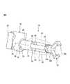
次に、図2〜図4を参照して、手首16について説明する。手首16は、ケーシング22に連結されており、第1の可動要素24、第2の可動要素26、および第3の可動要素28を有する。 Next, the
ケーシング22は、ロボットアーム14の先端部14aに、アーム軸15(図1)の周りに回転可能に連結されており、中空部30を含む。中空部30には、貫通孔32が形成されている。該貫通孔32は、第1の軸線34に沿って延在し、中空部30を貫通している。第1の軸線34は、アーム軸15の周りに回転する軸である。 The
第1の可動要素24は、第1の軸線34の周りに回転可能となるように、ケーシング22の中空部30に連結されている。第1の可動要素24は、(第1の)中空部36および(第1の)延長部38を有する。 The first
中空部36は、ケーシング22の中空部30の先端部30aから第1の軸線34に沿って延出している。中空部36の中心部には、第1の軸線34に沿って延在して該中空部36を貫通する貫通孔40が形成されている。この貫通孔40は、ケーシング22に形成された貫通孔32と連通している。 The
延長部38は、中空部36の先端部36aから第1の軸線34に沿って延出する中実の板状部材である。延長部38は、第1の部分42および第2の部分44を含む。第1の部分42は、中空部36の先端部36aに固定されている。第2の部分44は、第1の部分42の先端部42aから第1の軸線34に沿って延出する。第2の部分44は、第1の部分42よりも薄い厚さを有している。 The
第1の可動要素24は、ケーシング22の内部に収容された第1の駆動部25(図4)によって、回転駆動される。第1の駆動部25は、サーボモータ、およびサーボモータの出力シャフトに連結された第1の減速装置を含む。 The first
第2の可動要素26は、第1の可動要素24の第2の部分44の先端部44aに、第2の軸線46の周りに回転可能となるように連結されている。第2の軸線46は、第1の軸線34と直交し、且つ第1の軸線34周りに回転する軸線である。 The second
第2の可動要素26は、(第2の)中空部48および(第2の)延長部50を有する。中空部48の中心部には、該中空部48を貫通する貫通孔54が形成されている。貫通孔54は、第3の軸線52に沿って延在している。第3の軸線52は、第2の軸線46と直交し、且つ第2の軸線46の周りに回転する軸線である。 The second
延長部50は、中空部48の基端部48aから延出する板状部材であって、第1の可動要素24の第2の部分44の先端部44aに、第2の軸線46の周りに回転可能に連結されている。 The
第2の可動要素26は、第1の可動要素24の延長部38に取り付けられた第2の駆動部27(図4)によって、回転駆動される。第2の駆動部27は、サーボモータ、およびサーボモータの出力シャフトに連結された第2の減速装置を含む。 The second
第3の可動要素28は、第2の可動要素26の中空部48の内部に、第3の軸線52の周りに回転可能となるように配置されている。第3の可動要素28は、円筒状の部材であって、その中心部に、第3の軸線52に沿って延在して第3の可動要素28を貫通する貫通孔56(図5(c))が形成されている。貫通孔56は、第2の可動要素26に形成された貫通孔54と連通する。 The third
第3の可動要素28は、第2の可動要素26の中空部48に取り付けられた第3の駆動部29(図4)によって、回転駆動される。第3の駆動部29は、サーボモータ、およびサーボモータの出力シャフトに連結された第3の減速装置を含む。
The third
制御ボックス20は、ケーシング22に取り付けられており、エンドエフェクタ18を動作するための各種制御装置を内部に収容する。例えば、制御ボックス20は、エンドエフェクタ18の爪部18bを移動させるための圧縮流体の圧力を制御する制御装置を収容する。 The
エンドエフェクタ18は、第3の可動要素28の先端部28aに固定されている。エンドエフェクタ18は、手首16の動作によって、第1の軸線34、第2の軸線46、および第3の軸線52の周りに回動される。 The
ロボット10は、線条体58およびカバー60をさらに備える。本実施形態においては、線条体58は、その一端が制御ボックス20に収容された各制御装置に接続され、他端が、エンドエフェクタ18に接続されている。 The
制御ボックス20から引き出された線条体58は、ケーシング22の貫通孔32、第1の可動要素24の貫通孔40、第2の可動要素26の貫通孔54、および第3の可動要素28の貫通孔56の内部を通って、エンドエフェクタ18のベース18aの内部に引き込まれるように、配線される。線条体58は、第1の可動要素24の貫通孔40と第2の可動要素26の貫通孔54との間で、外部に露出されている。 The
本実施形態においては、図5(a)に示すように、線条体58が挿通されている第1の可動要素24の貫通孔40には、該貫通孔40を液密に封止するための(第1の)シール部材70が挿入されている。 In the present embodiment, as shown in FIG. 5A, in the through
また、図5(b)に示すように、第2の可動要素26の貫通孔54には、該貫通孔54を液密に封止するための(第1の)シール部材72が挿入されている。また、図5(c)に示すように、第3の可動要素28の貫通孔56には、該貫通孔56を液密に封止するための(第1の)シール部材74が設置されている。 Further, as shown in FIG. 5 (b), a (first)
また、図5(d)に示すように、エンドエフェクタ18のベース18aに形成されている孔18cには、該孔18cを液密に封止するための(第2の)シール部材76が設置されている。 Further, as shown in FIG. 5D, a (second)
カバー60は、可撓性の筒状部材であって、第1の開口端62と、該第1の開口端とは反対側の第2の開口端64とを有する。カバー60は、例えば、耐腐食性に優れた繊維材料から構成される。なお、図2〜図4においては、理解の容易の観点から、カバー60を点線によって示している。 The
本実施形態においては、第1の開口端62は、ケーシング22の中空部30と、第1の可動要素24の中空部36の先端部36aとの間に配置され、第1の可動要素24の中空部36の外面を環囲する。一方、第2の開口端64は、第2の可動要素26の中空部48の先端部48bとエンドエフェクタ18との間の隙間66(図4)に配置され、線条体58を環囲するように配置されている。 In the present embodiment, the first
このように、カバー60は、第1の可動要素24の中空部36の一部、延長部38、第2の可動要素26の全体、および第3の可動要素28の一部を取り囲むように、手首16に装着されている。 Thus, the
すなわち、カバー60は、第1の可動要素24の中空部36と第2の可動要素26の中空部48との間で延在して、第1の可動要素24の延長部38と第2の可動要素26の延長部50との連結部分を取り囲む。 That is, the
また、カバー60は、第2の可動要素26の中空部48と第3の可動要素28との間の連結部分を取り囲む。このように手首16に装着されたカバー60によって、第1の可動要素24の貫通孔40と第2の可動要素26の貫通孔54との間で外部に露出している線条体58の部分が、覆われることになる。 Also, the
図6は、第2の可動要素26が第1の可動要素24に対して第2の軸線46の周りに所定の角度だけ回転した状態を示している。本実施形態においては、線条体58は、第1の可動要素24の貫通孔40と第2の可動要素26の貫通孔54との間で外部に露出するように配線されている。 6 shows the second
したがって、図6に示すように第2の可動要素26が回転した場合、貫通孔40から外部に延出した線条体58は、貫通孔40と貫通孔54との間の区間で屈曲し、貫通孔54内へ引き込まれることになる。 Therefore, when the second
また、上述したように、カバー60は可撓性の部材によって構成されている。したがって、図6に示すように第2の可動要素26が回転したとしても、カバー60は、破断することなく、第2の可動要素26の回転動作に応じて撓むことができる。 Also, as described above, the
このように手首16に装着されたカバー60によって、ワークWを内部空間Sへ搬入または搬出する作業を実行しているときに、該内部空間Sに存在する切削液等の異物が、互いに連結された2つの可動要素24、26、28の間の連結部分から、手首16の内部へ侵入するのを防止できる。 Thus, when the work for carrying the work W into or out of the internal space S is performed by the
これにより、腐食性の切削液を使用している場合等において、手首16の内部へ進入した切削液によって、手首16の構成要素、および線条体58が損傷してしまうのを防止できる。 Thereby, when using a corrosive cutting fluid etc., it can prevent that the component of the
また、本実施形態においては、カバー60は、第1の可動要素24の中空部36から、第3の可動要素28の先端部28aに亘って、手首16の要素を取り囲むように装着されている。 Further, in the present embodiment, the
この構成によれば、第1の可動要素24の貫通孔40と第2の可動要素26の貫通孔54との間で外部に露出している線条体58を、カバー60によって確実に覆うことができる。このため、線条体58を切削液等の異物から効果的に防護できる。 According to this configuration, the
なお、第1の開口端62および第2の開口端64は、例えば、伸縮性のゴムリングから構成されてもよい。この場合、第1の開口端62および第2の開口端64において、カバー60の内部を封止することができるので、切削液等の異物がカバー60の内部へ侵入するのを、効果的に防止できる。 The first
また、本実施形態においては、貫通孔40、貫通孔54、貫通孔56、および孔18cは、それぞれ、シール部材70、シール部材72、シール部材74、およびシール部材76によって封止されている。これにより、切削液等の異物がこれら孔40、54、56、18cの内部へ侵入してしまうのをさらに確実に防止できる。
Further, in the present embodiment, the through
次に、図7および図8を参照して、他の実施形態に係るカバー80について説明する。カバー80は、筒状の部材であって、第1の開口端82と、該第1の開口端82とは反対側の第2の開口端84とを有する。 Next, a
カバー80は、第1の開口端82を含む円筒部86と、該円筒部86の先端部86aから延び、第2の開口端84を含む蛇腹部88とを有する。例えば、蛇腹部88は、円筒部86よりも高い可撓性を有しており、円筒部86と比べて、任意の方向へより容易に屈曲することができる。 The
図8は、本実施形態に係るカバー80を、図4に示す手首16に装着させた図を示す。図8に示すように、カバー80を手首16に装着させた状態においては、第1の開口端82は、第1の可動要素24の中空部36の外面を環囲するように配置される。一方、蛇腹部88は、第1の可動要素24と第2の可動要素26との連結部分を取り囲むように、配置されている。 FIG. 8 shows a view in which the
本実施形態に係るカバー80においては、図6に示すように第2の可動要素26が第1の可動要素24に対して回転した場合、蛇腹部88が、第2の可動要素26の回転移動に応じて、柔軟に屈曲する。これにより、第2の可動要素26の回転によってカバー80にストレスが掛かることを防止することができるので、カバーの破断を確実に防止しつつ、手首16の各要素や線条体58を切削液等の異物から防護することができる。 In the
なお、上述の実施形態においては、カバー60、80が、第1の可動要素24の中空部36から第3の可動要素28の先端部28aまで延在する場合について述べた。しかしながら、これに限らず、カバーは、互いに連結された2つの可動要素の間の連結部分を取り囲むように装着されてもよい。 In the above embodiment, the case where the
一例として、図9および図10に、上述した手首16の第2の可動要素26と第3の可動要素28との間の連結部分92を取り囲むように装着されたカバー90を示す。なお、図9および図10においては、理解の容易の観点から、カバー90を点線で示している。 As an example, FIGS. 9 and 10 show the
カバー90は、筒状の部材であって、第1の開口端94と、該第1の開口端94とは反対側の第2の開口端96とを有する。第1の開口端94は、第2の可動要素26の延長部50を環囲するように配置されている一方、第2の開口端96は、第3の可動要素28を環囲するように配置されている。 The
本実施形態係るカバー90によれば、エンドエフェクタ18により近い位置にある連結部分92から、切削液等の異物が手首16の内部に侵入するのを防止できる。したがって、第2の可動要素26および第3の可動要素28の内部で延在する線条体58を、異物から防護することができる。 According to the
なお、上述のカバー90は、第2の可動要素26の全体を取り囲むように構成されてもよい。このようなカバー90の変形例を、図11および図12に示す。図11および図12に示すカバー90’においては、第1の開口端94’が、第1の可動要素24の中空部36の先端部36aと、第2の可動要素26の延長部50の基端部50a(図12)との間に配置されている。 The above-described
これにより、カバー90’は、上述の連結部分92に加えて、第2の可動要素26の全体を取り囲むことになる。この構成によれば、エンドエフェクタ18により近い位置にある連結部分92と、第2の可動要素26の中空部48の基端部48aの双方において、切削液等の異物が手首16の内部に侵入するのを防止できる。また、第2の可動要素26を異物から防護することもできる。 As a result, the
なお、上述した実施形態においては、エンドエフェクタ18がロボットハンドである場合について述べた。しかしながら、エンドエフェクタ18は、例えば、ワークWを溶接可能な溶接トーチであってもよい。この場合、線条体58は、溶接ケーブルおよびコンジット等を含む。 In the embodiment described above, the case where the
また、図2〜図4に示す実施形態においては、カバー60の開口端64が、第3の可動要素28の先端部28aとエンドエフェクタ18との間に配置されている場合について述べた。 Furthermore, in the embodiment shown in FIGS. 2 to 4, the case where the
しかしながら、カバー60の開口端64は、第2の可動要素26の中空部48の基端部48aと該中空部48の先端部48bとの間の位置で、該中空部48の外面を環囲するように配置されてもよい。 However, the
換言すれば、カバー60は、第1の可動要素24の貫通孔40と第2の可動要素26の貫通孔54との間の領域において、手首16の構成要素および線条体58を取り囲むように、手首16に装着されてもよい。 In other words, the
この場合においても、カバー60によって、第1の可動要素24の貫通孔40と第2の可動要素26の貫通孔54との間で外部に露出された線条体58を、切削液等の異物から防護できる。 Also in this case, the
以上、発明の実施形態を通じて本発明を説明したが、上述の実施形態は、特許請求の範囲に係る発明を限定するものではない。また、本発明の実施形態の中で説明されている特徴を組み合わせた形態も本発明の技術的範囲に含まれ得るが、これら特徴の組み合わせの全てが、発明の解決手段に必須であるとは限らない。さらに、上述の実施形態に、多様な変更または改良を加えることが可能であることも当業者に明らかである。 As mentioned above, although the present invention was explained through an embodiment of the invention, the above-mentioned embodiment does not limit the invention concerning a claim. In addition, although a combination of the features described in the embodiments of the present invention may be included in the technical scope of the present invention, it is considered that all combinations of these features are essential to the solution of the invention. Not exclusively. Furthermore, it is also apparent to those skilled in the art that various changes or modifications can be added to the above-described embodiment.
10 ロボット
16 手首
18 エンドエフェクタ
24,26,28 可動要素
58 線条体
60,80,90,90’ カバーDESCRIPTION OF
Claims (4)
Translated fromJapanese前記ロボットアームの先端部に第1の軸線周りに回転可能に連結される第1の可動要素、および、該第1の可動要素の先端部に前記第1の軸線と直交する第2の軸線周りに回転可能に連結される第2の可動要素を有する手首であって、
前記第1の可動要素は、
前記ロボットアームの先端部に前記第1の軸線周りに回転可能に連結される第1の中空部と、
該第1の中空部から先端側へ延びる第1の延長部と、を有し、
前記第2の可動要素は、
第2の中空部と、
該第2の中空部から基端側へ延びる第2の延長部であって、前記第1の延長部の先端部に、前記第2の軸線周りに回転可能に連結される、第2の延長部と、を有する、手首と、
前記手首の先端部に連結されるエンドエフェクタと、
前記第1の中空部および前記第2の中空部の内部を通るように配線される線条体と、
前記第1の延長部と前記第2の延長部との連結部分と、前記第1の中空部と前記第2の中空部との間で延在する前記線条体とを取り囲んで該連結部分への外部からの異物の進入を防止するように前記手首に装着されるカバーと、を備え、
前記カバーは、
前記第1の中空部を取り囲むように配置された開口基端部、及び該開口基端部とは反対側の開口先端部を有する、円筒状の第1の部分であって、前記開口先端部は、前記第1の中空部よりも先端側へ離隔した位置に配置される、第1の部分と、
前記第1の部分の前記開口先端部から先端側へ延び、該第1の部分よりも高い可撓性を有する、蛇腹状の第2の部分であって、前記第1の延長部と前記第2の延長部との前記連結部分を取り囲むように配置される、第2の部分と、を有する、ロボット。With a robot arm,
Afirst movable elementrotatably coupled to a distal end ofthe robot armabout a first axis, and a second axis orthogonal to the first axis at a distal end of the first movable element A wristhaving a second movable element rotatably coupled to the
The first movable element is
A first hollow portion rotatably coupled to the distal end portion of the robot arm about the first axis;
And a first extension portion extending distally from the first hollow portion,
The second movable element is
A second hollow portion,
A second extension extending proximally from the second hollow portion, the second extension rotatably coupled to a distal end of the first extension about the second axis. With the wrist, with the wrist,
An end effector coupled to the tip of the wrist;
And striatum are wired asbefore Symbol pass through the inside of thefirst hollow portion and the second hollow portion,
The connection portion surrounding the connection portionbetweenthe first extension portion and the second extension portion and thelinear body extending between the first hollow portion and the second hollow portion A cover attached to the wrist so as to prevent entry of foreign objects from the outside into the housing;
The cover is
A cylindrical first portion having an open proximal end disposed to surround the first hollow portion, and an open distal end opposite to the open proximal end, the open distal end A first portion disposed at a position more distal to the first hollow portion than the first hollow portion ;
A secondbellows-like portion extending distally from theopenend of the first portion and havinga higher flexibility than the first portion,the first extension and the first portion; And a second portion disposed to surround the connection portionwith the two extension portions .
前記エンドエフェクタは、前記第3の可動要素の先端部に固定され、
前記第2の部分は、前記第2の可動要素と前記第3の可動要素との間の連結部分をさらに取り囲む、請求項1に記載のロボット。The third movable movablely connected to the second movable element about a third axis orthogonal to the second axis so that the wrist is opposite to the first movable element. Have more elements,
The end effector is fixed to the tip of the third movable element,
Said second portion, said secondfurther surrounds theconsolidated portionbetween said movable element third movable element, the robot according to claim1.
前記ロボットは、前記孔を液密に封止する第2のシール部材をさらに備える、請求項1〜3のいずれか1項に記載のロボット。The end effector has a hole for receiving the filament extending fromthe second hollow portion ,
The robot according to any one of claims 1 to3 , wherein the robot further comprises a second seal member sealing the hole in a fluid-tight manner.
Priority Applications (4)
| Application Number | Priority Date | Filing Date | Title |
|---|---|---|---|
| JP2015181617AJP6538498B2 (en) | 2015-09-15 | 2015-09-15 | Robot with a wrist having a hollow movable element and a waterproof structure |
| CN201610806890.4ACN106514688B (en) | 2015-09-15 | 2016-09-07 | Robot |
| DE102016116812.2ADE102016116812A1 (en) | 2015-09-15 | 2016-09-08 | Robot provided with a wrist containing a hollow movable element and having a watertight structure |
| US15/264,991US10661454B2 (en) | 2015-09-15 | 2016-09-14 | Robot provided with wrist including hollow movable element and having waterproof structure |
Applications Claiming Priority (1)
| Application Number | Priority Date | Filing Date | Title |
|---|---|---|---|
| JP2015181617AJP6538498B2 (en) | 2015-09-15 | 2015-09-15 | Robot with a wrist having a hollow movable element and a waterproof structure |
Publications (2)
| Publication Number | Publication Date |
|---|---|
| JP2017056501A JP2017056501A (en) | 2017-03-23 |
| JP6538498B2true JP6538498B2 (en) | 2019-07-03 |
Family
ID=58160911
Family Applications (1)
| Application Number | Title | Priority Date | Filing Date |
|---|---|---|---|
| JP2015181617AActiveJP6538498B2 (en) | 2015-09-15 | 2015-09-15 | Robot with a wrist having a hollow movable element and a waterproof structure |
Country Status (4)
| Country | Link |
|---|---|
| US (1) | US10661454B2 (en) |
| JP (1) | JP6538498B2 (en) |
| CN (1) | CN106514688B (en) |
| DE (1) | DE102016116812A1 (en) |
Families Citing this family (12)
| Publication number | Priority date | Publication date | Assignee | Title |
|---|---|---|---|---|
| JP6572270B2 (en)* | 2017-09-08 | 2019-09-04 | ファナック株式会社 | Robot with hollow wrist element |
| US11312006B2 (en)* | 2018-03-30 | 2022-04-26 | Fanuc Corporation | Robot drive unit and robot |
| US11007638B2 (en)* | 2018-12-20 | 2021-05-18 | Honda Motor Co., Ltd. | Telescoping support robot and methods of use thereof |
| JP7048538B2 (en) | 2019-04-25 | 2022-04-05 | ファナック株式会社 | Industrial robots and how to extend their reach |
| US11820011B2 (en)* | 2019-05-17 | 2023-11-21 | Kinova Inc. | Robot arm with skeleton and skin shell construction |
| JP7388887B2 (en) | 2019-11-13 | 2023-11-29 | ファナック株式会社 | Robot striatal unit and striatal wiring method |
| TWI881191B (en)* | 2020-12-08 | 2025-04-21 | 日商發那科股份有限公司 | Insulation cover, bracket, robot, welding device and robot system |
| WO2022215197A1 (en)* | 2021-04-07 | 2022-10-13 | ファナック株式会社 | Tool drive device and robot |
| CN117241919A (en) | 2021-04-28 | 2023-12-15 | 发那科株式会社 | Robot |
| US12240104B2 (en) | 2021-05-14 | 2025-03-04 | Fanuc Corporation | Wrist cover, robot, and wrist cover set |
| CN118103185A (en)* | 2021-10-22 | 2024-05-28 | 发那科株式会社 | Covering member fixing structure, machine and robot |
| US11993498B2 (en)* | 2021-10-28 | 2024-05-28 | Toyota Research Institute, Inc. | Structures and sensor assemblies having engagement structures for securing a compliant substrate assembly |
Family Cites Families (35)
| Publication number | Priority date | Publication date | Assignee | Title |
|---|---|---|---|---|
| JPS6263088A (en)* | 1985-09-10 | 1987-03-19 | 川崎重工業株式会社 | Dust-proof and liquid-proof structure for industrial robots |
| US4762455A (en)* | 1987-06-01 | 1988-08-09 | Remote Technology Corporation | Remote manipulator |
| US4904514A (en)* | 1988-09-13 | 1990-02-27 | Kimberly-Clark Corporation | Protective covering for a mechanical linkage |
| JPH0283192A (en)* | 1988-09-20 | 1990-03-23 | Tokico Ltd | industrial robot |
| JP3491780B2 (en)* | 1994-12-07 | 2004-01-26 | 株式会社安川電機 | Lead wire processing structure for industrial robots |
| JPH0957680A (en)* | 1995-08-18 | 1997-03-04 | Tokico Ltd | Industrial robot |
| US7666191B2 (en)* | 1996-12-12 | 2010-02-23 | Intuitive Surgical, Inc. | Robotic surgical system with sterile surgical adaptor |
| CA2213287A1 (en)* | 1997-08-18 | 1999-02-18 | Clement Tessier | Apparatus for shielding an articulated structure |
| US6082290A (en)* | 1997-09-15 | 2000-07-04 | Conlin; Douglas | Paint spray booth with robot |
| US6042624A (en)* | 1998-04-03 | 2000-03-28 | Medtronic, Inc. | Method of making an implantable medical device having a flat electrolytic capacitor |
| US6346150B1 (en)* | 1998-06-19 | 2002-02-12 | Douglas Conlin | Paint spray booth with robot |
| DE60232584D1 (en)* | 2001-01-23 | 2009-07-23 | Honda Motor Co Ltd | HAND DEVICE WITH SEVERAL FINGERS |
| JP4142304B2 (en)* | 2001-10-22 | 2008-09-03 | 株式会社安川電機 | Arc welding robot |
| JP3739756B2 (en)* | 2003-03-31 | 2006-01-25 | ファナック株式会社 | Wiring and piping processing equipment |
| MXPA04006252A (en)* | 2003-06-23 | 2005-02-24 | Td Ind Coverings | Robot cover. |
| JP2005014159A (en)* | 2003-06-26 | 2005-01-20 | Fanuc Ltd | Robot |
| US20060165953A1 (en)* | 2004-11-29 | 2006-07-27 | T D Industrial Covering, Inc. | Ring assembly for a covered paint robot |
| US8585854B2 (en)* | 2007-03-27 | 2013-11-19 | Butterworth Industries, Inc. | Polymeric cover for robots |
| DE102008005901B4 (en)* | 2008-01-24 | 2018-08-09 | Deutsches Zentrum für Luft- und Raumfahrt e.V. | Sterile barrier for a surgical robot with torque sensors |
| JP5289125B2 (en)* | 2009-03-24 | 2013-09-11 | ファナック株式会社 | Robot system with articulated robot |
| KR20110080919A (en)* | 2010-01-07 | 2011-07-13 | 삼성전자주식회사 | robot |
| BR112012022249A2 (en)* | 2010-03-01 | 2016-10-25 | Abb As | facility adapted for extraction or production of petroleum products in a hostile external environment and method for operating an industrial robot in that facility |
| JP5344315B2 (en)* | 2010-11-04 | 2013-11-20 | 株式会社安川電機 | Robot wrist structure and robot |
| JP5833901B2 (en)* | 2011-11-30 | 2015-12-16 | 川崎重工業株式会社 | Articulated industrial robot |
| JP5539454B2 (en)* | 2012-07-20 | 2014-07-02 | ファナック株式会社 | Striated structure for industrial robot with hollow member |
| JP5660401B2 (en)* | 2012-11-19 | 2015-01-28 | 株式会社安川電機 | Robot equipment |
| US10105727B2 (en)* | 2013-01-09 | 2018-10-23 | Td Industrial Coverings, Inc. | Apparatus for preventing a cover from being drawn into an axis joint of a paint robot and related method |
| DE102013002813B4 (en)* | 2013-02-19 | 2017-11-09 | Rg Mechatronics Gmbh | Holding device with at least one jaw for a robotic surgical system |
| JP5835276B2 (en)* | 2013-06-24 | 2015-12-24 | 株式会社安川電機 | Robot, robot manufacturing method and bag |
| CN104608125B (en)* | 2013-11-01 | 2019-12-17 | 精工爱普生株式会社 | Robots, controls and robotic systems |
| JP5902664B2 (en)* | 2013-12-25 | 2016-04-13 | ファナック株式会社 | Human cooperative industrial robot with protective member |
| JP6267612B2 (en)* | 2014-09-22 | 2018-01-24 | 株式会社ホギメディカル | Medical robot cover |
| DE102014117407A1 (en)* | 2014-11-27 | 2016-06-02 | avateramedical GmBH | Device for robotic surgery |
| WO2017015207A1 (en)* | 2015-07-23 | 2017-01-26 | Think Surgical, Inc. | Protective drape for robotic systems |
| DE202015009616U1 (en)* | 2015-08-14 | 2018-08-30 | Franka Emika Gmbh | Robot system and housing part for such a robot system |
- 2015
- 2015-09-15JPJP2015181617Apatent/JP6538498B2/enactiveActive
- 2016
- 2016-09-07CNCN201610806890.4Apatent/CN106514688B/enactiveActive
- 2016-09-08DEDE102016116812.2Apatent/DE102016116812A1/enactivePending
- 2016-09-14USUS15/264,991patent/US10661454B2/enactiveActive
Also Published As
| Publication number | Publication date |
|---|---|
| US20170072573A1 (en) | 2017-03-16 |
| JP2017056501A (en) | 2017-03-23 |
| CN106514688A (en) | 2017-03-22 |
| US10661454B2 (en) | 2020-05-26 |
| CN106514688B (en) | 2021-04-27 |
| DE102016116812A1 (en) | 2017-03-16 |
Similar Documents
| Publication | Publication Date | Title |
|---|---|---|
| JP6538498B2 (en) | Robot with a wrist having a hollow movable element and a waterproof structure | |
| US9806457B2 (en) | Articulated robot with connection member for connecting wire body arranged on arm | |
| JP3987845B2 (en) | Striated structure of industrial robot | |
| US9278455B2 (en) | Robot joint structure | |
| CN105788739B (en) | Composite cable | |
| CN103978479B (en) | Horizontal articulated mechanical hand | |
| US10093024B2 (en) | Robot linear-object handling structure | |
| US20140020498A1 (en) | Umbilical member arrangement structure of industrial robot having hollow member | |
| CN103934832B (en) | Robot | |
| CN103934831A (en) | Robot | |
| TW201502396A (en) | Cable-routing device comprising multiaxially bendable links | |
| WO2008044348A1 (en) | Industrial robot | |
| CN102463571A (en) | Robot wrist structure and robot | |
| KR20130129852A (en) | Industrial robot with drives which extend in a hand basic housing | |
| CN110202611B (en) | robot | |
| CN106103015A (en) | Laser processing robot | |
| JP2015104764A (en) | Arm mechanism | |
| KR102578354B1 (en) | Ceiling-suspended industrial robot | |
| JP2007015053A (en) | Industrial robot | |
| TW201801873A (en) | Robot arm mechanism and rotational joint mechanism | |
| JP5833901B2 (en) | Articulated industrial robot | |
| JP7428050B2 (en) | Rotating module and robot | |
| JP7388887B2 (en) | Robot striatal unit and striatal wiring method | |
| JP6967524B2 (en) | Detachable wrist joint | |
| JP7110782B2 (en) | Attachments, jackets for robots |
Legal Events
| Date | Code | Title | Description |
|---|---|---|---|
| A131 | Notification of reasons for refusal | Free format text:JAPANESE INTERMEDIATE CODE: A131 Effective date:20170808 | |
| A521 | Written amendment | Free format text:JAPANESE INTERMEDIATE CODE: A523 Effective date:20171005 | |
| A131 | Notification of reasons for refusal | Free format text:JAPANESE INTERMEDIATE CODE: A131 Effective date:20180327 | |
| A521 | Written amendment | Free format text:JAPANESE INTERMEDIATE CODE: A523 Effective date:20180511 | |
| A131 | Notification of reasons for refusal | Free format text:JAPANESE INTERMEDIATE CODE: A131 Effective date:20180925 | |
| A521 | Written amendment | Free format text:JAPANESE INTERMEDIATE CODE: A523 Effective date:20181115 | |
| TRDD | Decision of grant or rejection written | ||
| A01 | Written decision to grant a patent or to grant a registration (utility model) | Free format text:JAPANESE INTERMEDIATE CODE: A01 Effective date:20190507 | |
| A61 | First payment of annual fees (during grant procedure) | Free format text:JAPANESE INTERMEDIATE CODE: A61 Effective date:20190606 | |
| R150 | Certificate of patent or registration of utility model | Ref document number:6538498 Country of ref document:JP Free format text:JAPANESE INTERMEDIATE CODE: R150 |