JP6537979B2 - Gusset bag, method of manufacturing gusset bag, and method of joining laminates - Google Patents
Gusset bag, method of manufacturing gusset bag, and method of joining laminatesDownload PDFInfo
- Publication number
- JP6537979B2 JP6537979B2JP2015559155AJP2015559155AJP6537979B2JP 6537979 B2JP6537979 B2JP 6537979B2JP 2015559155 AJP2015559155 AJP 2015559155AJP 2015559155 AJP2015559155 AJP 2015559155AJP 6537979 B2JP6537979 B2JP 6537979B2
- Authority
- JP
- Japan
- Prior art keywords
- gusset
- bag
- bonding
- portions
- gusset bag
- Prior art date
- Legal status (The legal status is an assumption and is not a legal conclusion. Google has not performed a legal analysis and makes no representation as to the accuracy of the status listed.)
- Active
Links
Images


Classifications
- B—PERFORMING OPERATIONS; TRANSPORTING
- B65—CONVEYING; PACKING; STORING; HANDLING THIN OR FILAMENTARY MATERIAL
- B65D—CONTAINERS FOR STORAGE OR TRANSPORT OF ARTICLES OR MATERIALS, e.g. BAGS, BARRELS, BOTTLES, BOXES, CANS, CARTONS, CRATES, DRUMS, JARS, TANKS, HOPPERS, FORWARDING CONTAINERS; ACCESSORIES, CLOSURES, OR FITTINGS THEREFOR; PACKAGING ELEMENTS; PACKAGES
- B65D31/00—Bags or like containers made of paper and having structural provision for thickness of contents
- B65D31/10—Bags or like containers made of paper and having structural provision for thickness of contents with gusseted sides
- B—PERFORMING OPERATIONS; TRANSPORTING
- B31—MAKING ARTICLES OF PAPER, CARDBOARD OR MATERIAL WORKED IN A MANNER ANALOGOUS TO PAPER; WORKING PAPER, CARDBOARD OR MATERIAL WORKED IN A MANNER ANALOGOUS TO PAPER
- B31B—MAKING CONTAINERS OF PAPER, CARDBOARD OR MATERIAL WORKED IN A MANNER ANALOGOUS TO PAPER
- B31B70/00—Making flexible containers, e.g. envelopes or bags
- B31B70/60—Uniting opposed surfaces or edges; Taping
- B31B70/64—Uniting opposed surfaces or edges; Taping by applying heat or pressure
- B31B70/643—Uniting opposed surfaces or edges; Taping by applying heat or pressure on piled sheets, e.g. sealing bags arranged in a pile
- B—PERFORMING OPERATIONS; TRANSPORTING
- B65—CONVEYING; PACKING; STORING; HANDLING THIN OR FILAMENTARY MATERIAL
- B65D—CONTAINERS FOR STORAGE OR TRANSPORT OF ARTICLES OR MATERIALS, e.g. BAGS, BARRELS, BOTTLES, BOXES, CANS, CARTONS, CRATES, DRUMS, JARS, TANKS, HOPPERS, FORWARDING CONTAINERS; ACCESSORIES, CLOSURES, OR FITTINGS THEREFOR; PACKAGING ELEMENTS; PACKAGES
- B65D75/00—Packages comprising articles or materials partially or wholly enclosed in strips, sheets, blanks, tubes or webs of flexible sheet material, e.g. in folded wrappers
- B65D75/008—Standing pouches, i.e. "Standbeutel"
- B—PERFORMING OPERATIONS; TRANSPORTING
- B31—MAKING ARTICLES OF PAPER, CARDBOARD OR MATERIAL WORKED IN A MANNER ANALOGOUS TO PAPER; WORKING PAPER, CARDBOARD OR MATERIAL WORKED IN A MANNER ANALOGOUS TO PAPER
- B31B—MAKING CONTAINERS OF PAPER, CARDBOARD OR MATERIAL WORKED IN A MANNER ANALOGOUS TO PAPER
- B31B2150/00—Flexible containers made from sheets or blanks, e.g. from flattened tubes
- B31B2150/002—Flexible containers made from sheets or blanks, e.g. from flattened tubes by joining superimposed sheets, e.g. with separate bottom sheets
- B—PERFORMING OPERATIONS; TRANSPORTING
- B31—MAKING ARTICLES OF PAPER, CARDBOARD OR MATERIAL WORKED IN A MANNER ANALOGOUS TO PAPER; WORKING PAPER, CARDBOARD OR MATERIAL WORKED IN A MANNER ANALOGOUS TO PAPER
- B31B—MAKING CONTAINERS OF PAPER, CARDBOARD OR MATERIAL WORKED IN A MANNER ANALOGOUS TO PAPER
- B31B2160/00—Shape of flexible containers
- B31B2160/20—Shape of flexible containers with structural provision for thickness of contents
- B—PERFORMING OPERATIONS; TRANSPORTING
- B31—MAKING ARTICLES OF PAPER, CARDBOARD OR MATERIAL WORKED IN A MANNER ANALOGOUS TO PAPER; WORKING PAPER, CARDBOARD OR MATERIAL WORKED IN A MANNER ANALOGOUS TO PAPER
- B31B—MAKING CONTAINERS OF PAPER, CARDBOARD OR MATERIAL WORKED IN A MANNER ANALOGOUS TO PAPER
- B31B70/00—Making flexible containers, e.g. envelopes or bags
- B31B70/60—Uniting opposed surfaces or edges; Taping
Landscapes
- Engineering & Computer Science (AREA)
- Mechanical Engineering (AREA)
- Bag Frames (AREA)
- Making Paper Articles (AREA)
Description
Translated fromJapanese本発明は、ガゼット袋、ガゼット袋の製造方法、及び積層体の接合方法に関するものである。 The present invention relates to a gusset bag, a method of manufacturing the gusset bag, and a method of joining laminates.
袋は、例えば、熱融着性を有するシーラント層と耐熱性を有する基材層とが積層された積層フィルムによって形成される。シーラント層が袋の内側表面を形成し、基材層が袋の外側表面を形成する。 The bag is formed of, for example, a laminated film in which a heat-sealing sealant layer and a heat-resistant substrate layer are laminated. The sealant layer forms the inner surface of the bag and the substrate layer forms the outer surface of the bag.
袋を形成するために積層フィルム同士を接合する方法としては、積層フィルムの外部にある熱源により、熱伝導、輻射、及び対流等によって積層フィルムの表面から徐々に内部へ加熱が進む外部加熱による方法と、積層フィルムそのものが自己発熱することにより、内部と外部が同時並行的に加熱される内部加熱による方法とがある。外部加熱による方法としては、熱板シール(以下単に「ヒートシール」ともいう。)、インパルスシール等による方法があり、内部加熱による方法としては、高周波シール、超音波シール等による方法がある。
内部加熱である超音波シールでは、微細な超音波振動によって生じる摩擦熱と加圧力によって積層フィルム同士を瞬時に溶融させて接合する。なお、超音波シールは、超音波振動により、積層フィルム同士が擦れて屑が発生する場合がある。その結果、発生した屑が袋内へ異物として混入する可能性がある。As a method of joining laminated films together to form a bag, there is a method by external heating in which heating gradually advances from the surface of the laminated film to the inside by heat conduction, radiation, convection and the like by a heat source outside the laminated film. In addition, there is a method by internal heating in which the inside and the outside are simultaneously heated in parallel by self-heating of the laminated film itself. As a method by external heating, there is a method by a heat plate seal (hereinafter, also simply referred to as "heat seal"), an impulse seal or the like, and as a method by internal heating, there is a method by a high frequency seal, an ultrasonic seal or the like.
In ultrasonic sealing, which is internal heating, laminated films are instantaneously melted and joined together by frictional heat and pressure force generated by fine ultrasonic vibration. In the ultrasonic seal, laminated films may be rubbed with each other by ultrasonic vibration to generate scraps. As a result, the generated waste may be mixed into the bag as foreign matter.
また、図12に示されるようにガゼット袋100は、対向する一対の平面部102A,102B及びこれら平面部102A,102Bの両側に設けられた横ガゼット部104を有する。ガゼット袋100は、内表面層106が熱融着性を有するシーラント層とされ、外表面層108が耐熱性を有する基材層とされる。
このため、図13に示されるように、平面部102A,102Bの上部や下部を閉じるために、例えばヒートシールを用いた開放端シール部110が施されても、開放端シール部110の両側部110Aでは、対向する横ガゼット部104の外表面層108同士が接合されない。この結果、横ガゼット部104の上部や下部が開いた状態となる。このような状態では、ガゼット袋100の外観が劣ることとなる。
また、開放端シール部110と内容物の収容部分との境界部のうち、横ガゼット部104の折込部との交点110Bは、上記横ガゼット部104が開いた状態では、最も応力が集中し易い。このため、誤ってガゼット袋100を落下させた場合等に、応力が集中した交点110Bから破袋が生じる可能性がある。Further, as shown in FIG. 12, the
For this reason, as shown in FIG. 13, even if the open
Further, among the boundary portions between the open
そこで、図14に示されるように、横ガゼット部104の上端である開放端シール部110の両側部110Aを接合して、横ガゼット部104の開きを閉じたガゼット袋100が開発されている。これにより、ガゼット袋100の外観が向上され、かつ破袋が防止される。 Therefore, as shown in FIG. 14, a
このような横ガゼット部の開きを閉じる技術として、特許文献1には、横ガゼット部の一部の積層フィルムを除去して貫通孔を設け、貫通孔を通じて一対の平面部の内表面層同士を接合することで、一対の平面部を一体化させたガゼット袋が開示されている。
しかし、このようなガゼット袋100は、貫通孔を形成するために切除されて発生した小さなフィルム片が、ガゼット袋100の内部に混入したり、このフィルム片が次工程に搬送されることでシール不良を起こす可能性があった。As a technique for closing the opening of such a horizontal gusset portion, Patent Document 1 removes a part of the laminated film of the horizontal gusset portion to form a through hole, and the inner surface layers of a pair of flat portions are formed through the through holes. A gusset bag in which a pair of flat portions are integrated by joining is disclosed.
However, in such a
また、図15は、底ガゼット部112を有するガゼット袋120の下部を示した図であり、図15(A)はガゼット袋120の正面図、図15(B)は底ガゼット部112の斜視図である。なお、ハッチングで示される領域は、ガゼット袋120を形成する積層フィルムが接合されている領域である。
底ガゼット部112は、一対の平面部102A,102Bに接合された場合に、外側表面となる外表面層108が耐熱性を有する基材層によって形成されているため、外表面層108同士は通常であれば接合しない。
そこで、底ガゼット部112の側部の一部が切欠かれることで、底ガゼット部112と平面部102A,102Bとが接合されたとき、切欠き部分112Aを通じて平面部102A,102Bの内表面層106同士が接合される。これにより、一対の平面部102A,102Bが一体化され、ガゼット袋120の側部において底が開くことを防止し、ガゼット袋120の自立機能が発現する。
しかし、このようなガゼット袋120は、切欠き部分112Aを形成するために切除されて発生した小さなフィルム片が、ガゼット袋120の内部に混入したり、このフィルム片が次工程に搬送されることでシール不良を起こす可能性があった。15 is a view showing the lower part of the
When the
Therefore, when the
However, such a
以上、ここまで説明したガゼット袋は、横ガゼット袋及び底ガゼット袋共に、ガゼット袋を形成する平面部及びガゼット部の各部が別部材とされる場合、ガゼット袋の製造工程では、特許文献1に記載されている貫通孔の位置を容易に合わせることができる。しかし、ガゼット袋には平面部及びガゼット部の各部が一枚の積層フィルムで形成され、積層フィルムを折ることで各部が形成されるものもある。このようなガゼット袋の場合、ガゼット部に貫通孔を設けることは、製造工程が煩雑となる。また、一枚の積層フィルムが折り込まれてガゼット部が形成されるため、貫通孔の位置がずれる可能性があり、ガゼット部で揃った位置に貫通孔を開けること自体が困難であった。 As described above, in the case of the gusset bag, when the flat part forming the gusset bag and the respective parts of the gusset part are separate members in both the lateral gusset bag and the bottom gusset bag, Patent Document 1 describes the manufacturing process of the gusset bag. The positions of the described through holes can be easily aligned. However, in the gusset bag, there are some in which each part of the flat part and the gusset part is formed of one laminated film, and each part is formed by folding the laminated film. In the case of such a gusset bag, providing the through hole in the gusset part complicates the manufacturing process. In addition, since a single laminated film is folded to form a gusset portion, there is a possibility that the position of the through hole may be shifted, and it was difficult to open the through hole at a position aligned with the gusset portion itself.
そこで、特許文献2には、底ガゼット部を有する自立袋において、底部材に二本の切断線を設け、二本の切断線間に設けられた帯状部分を折り曲げて船底シール部内の未シール部に位置するように形成させ、帯状部分の折り返し跡において、二枚の本体フィルムの表側フィルムと裏側フィルムが密着シールされ、包装袋の底のガゼットが開くことがなく自立性を維持できる自立性包装袋が開示さている。 Therefore, in Patent Document 2, in a self-supporting bag having a bottom gusset portion, two cutting lines are provided on the bottom member, and a band-like portion provided between the two cutting lines is bent to form an unsealed portion in the bottom seal portion. The self-supporting packaging can maintain self-supporting property without opening the bottom gusset of the packaging bag by closely sealing the front side film and the back side film of the two main body films in the folding mark of the strip portion. A bag is disclosed.
しかしながら、特許文献2の自立性包装袋においても、二本の切断線が平行とならずに、交差してしまうと切り欠きとなり、フィルム片が袋から切除されてガゼット袋の内部に混入する可能性がある。また、二本の切断線間に設けられた帯状部分が折り曲げられて船底シール部内の未シール部に位置するように形成されるので、表面に凹凸が発生して外観が劣る。さらに、切断線が延びることによってガゼット袋が大きく破れる可能性がある。 However, even in the case of the self-supporting packaging bag of Patent Document 2, the two cutting lines do not become parallel, and if they cross each other, they become notches, and a piece of film can be cut out of the bag and mixed inside the gusset bag There is sex. In addition, since the belt-like portion provided between the two cutting lines is bent to be positioned at the unsealed portion in the bottom seal portion, unevenness is generated on the surface and the appearance is inferior. Furthermore, the extension of the cutting line may cause the gusset bag to be greatly broken.
本発明は、このような事情に鑑みてなされたものであって、ガゼット部を閉じる工程においてフィルム片や屑が袋内に混入することを防止すると共に、簡易にガゼット部を閉じることができる、ガゼット袋、ガゼット袋の製造方法、及び積層体の接合方法を提供することを目的とする。 The present invention has been made in view of such circumstances, and in the process of closing the gusset, it is possible to prevent film pieces and debris from being mixed in the bag, and to easily close the gusset. A gusset bag, a method of manufacturing the gusset bag, and a method of joining laminates.
上記課題を解決するために、本発明のガゼット袋、ガゼット袋の製造方法、及び積層体の接合方法は以下の手段を採用する。 In order to solve the above problems, the gusset bag, the method of manufacturing the gusset bag, and the method of joining laminates according to the present invention employ the following means.
本発明の第一態様に係るガゼット袋は、対向する一対の平面部と、袋の内方に折り込まれるガゼット部と、前記平面部の側部と前記ガゼット部の側部とを、内側表面同士で接合した第1接合部と、他の前記平面部の側部と前記ガゼット部の他の側部とを、内側表面同士で接合した第2接合部と、前記第1接合部と前記第2接合部とを前記ガゼット部の外側表面同士で、超音波シールによって接合した第3接合部と、を備え、前記第3接合部はガゼット袋の端部と接しない。In the gusset bag according to the first aspect of the present invention, a pair of opposing flat portions, a gusset portion to be folded inward of the bag, a side portion of the flat portion and a side portion of the gusset portion A second joint in which the first joint joined in the step, the other side of the flat face and the other side of the gusset are joined together at the inner surfaces, the first joint and the second joint And a third joint portion joined to each other by an ultrasonic seal at outer surfaces of the gusset portion, andthe third joint portion is not in contact with the end portion of the gusset bag .
本構成に係るガゼット袋は、対向する一対の平面部と袋の内方に折り込まれるガゼット部とを備える。 The gusset bag which concerns on this structure is equipped with a pair of opposing flat part and the gusset part folded inward of a bag.
平面部の側部とガゼット部の側部とが、第1接合部によって内側表面同士で接合される。また、他の平面部の側部とガゼット部の他の側部とが、第2接合部によって内側表面同士で接合される。第1接合部及び第2接合部は、例えばヒートシールによって接合される。第1接合部及び第2接合部は、特に、ヒートシールに限定されないが、内側表面同士の接合であるため、例えば、超音波シールによる接合を行った場合、超音波振動による積層フィルム同士の擦れで発生した屑が袋の内部に浸入してしまう恐れがあるため、好ましくない。 The side portions of the flat portion and the side portions of the gusset portion are joined at the inner surfaces by a first joint. Also, the sides of the other flats and the other sides of the gusset are joined at the inner surfaces by the second joint. The first joint and the second joint are joined, for example, by heat sealing. The first bonding portion and the second bonding portion are not particularly limited to heat sealing, but are bonding of the inner surfaces to each other. For example, when bonding by ultrasonic sealing is performed, rubbing of laminated films due to ultrasonic vibration is caused. It is not preferable because there is a risk that waste generated in the above may intrude into the inside of the bag.
さらに、第3接合部によって、第1接合部と第2接合部とがガゼット部の外側表面同士で接合される。第3接合部による接合が行われないと、ガゼット部は外側表面同士で接合されないため、開いた状態となっている。ガゼット部に第3接合部による接合が行われることにより、ガゼット部の開いた状態が閉じられることとなる。第3接合部による接合は、例えばガゼット袋の両端近辺に行われる。
第3接合部による接合は、超音波シールにより行われる。ガゼット部の外側表面が耐熱性を有していると、ヒートシール等の外部加熱では、外側表面のフィルムより先に内側表面のフィルムが溶融してしまう。このため、外側表面を溶融させようとすると、積層フィルムの殆どが溶融してしまうため、外部加熱による接合が適さないためである。
上述の通り、超音波シールによる接合は、摩擦により接合させる2面を擦れ合わせるため屑が生じる場合がある。しかし、第3接合部による接合は、ガゼット部の外側表面同士であり、擦れ合わされることによって屑が生じた場合でも、この部分は、ガゼット袋の外側である。このため、屑が生じても、ガゼット袋内に屑が混入することはない。なお、袋の内側となる第1接合部及び第2接合部は、すでに接合されているため、第3接合部を接合する際にも、この部分で擦れ合うことはなく、屑は生じない。Furthermore, the first bonding portion and the second bonding portion are bonded together at the outer surfaces of the gusset portions by the third bonding portion. Since the gusset portions are not joined at the outer surfaces when the third joining portion is not joined, the gusset portions are in an open state. Bonding by the third joint to the gusset part will close the open state of the gusset part. Joining by the third joint is performed, for example, near both ends of the gusset bag.
Bonding by the third bonding portion is performed by ultrasonic sealing. If the outer surface of the gusset has heat resistance, the film on the inner surface melts earlier than the film on the outer surface by external heating such as heat sealing. For this reason, if it is going to fuse | melt the outer surface, since most laminated films will fuse, it is because joining by external heating is not suitable.
As described above, bonding by ultrasonic sealing may generate scraps because the two surfaces to be bonded are rubbed together by friction. However, the bonding by the third bonding portion is the outer surfaces of the gusset portion, and this portion is the outside of the gusset bag even if scraps are generated due to the rubbing. For this reason, even if waste is generated, the waste is not mixed in the gusset bag. In addition, since the 1st junction part and the 2nd junction part which become the inner side of a bag are already joined, also when joining a 3rd junction part, it does not rub in this part and scraps do not arise.
従って、本構成は、ガゼット部を閉じる工程においてフィルム片や屑が袋内に混入することを防止できると共に、簡易にガゼット部を閉じることができる。 Therefore, this configuration can prevent film pieces and debris from being mixed in the bag in the process of closing the gusset, and can easily close the gusset.
上記第一態様では、一対の前記平面部及び前記ガゼット部が、フィルムが折られて区画されることで形成されることが好ましい。 In the said 1st aspect, it is preferable that a pair of said plane part and said gusset part are formed by a film being folded and divided.
本構成によれば、平面部とガゼット部が、フィルムが折られて区画されることで形成されており、ガゼット部を閉じる工程においてフィルム片や屑が袋内に混入することを防止すると共に、簡易にガゼット部を閉じることができる。さらに、フィルムが折られて平面部とガゼット部が区画されているため、利用者が手で持つ部分には硬い側部ヒートシール部が形成されていないため、手で持った際の痛みが緩和される。 According to this configuration, the flat portion and the gusset portion are formed by folding and dividing the film, and in the process of closing the gusset portion, film pieces and debris are prevented from being mixed into the bag, and You can easily close the gusset. Furthermore, since the film is folded to separate the flat portion and the gusset portion, the hard side heat seal portion is not formed at the portion held by the user, so the pain when held by the hand is alleviated. Be done.
上記第一態様では、一対の前記平面部が、各々一枚のフィルムで形成され、前記ガゼット部は、一枚のフィルムで形成されることが好ましい。 In the said 1st aspect, it is preferable that a pair of said plane part is each formed by one film, and the said gusset part is formed by one film.
本構成によれば、一対の平面部とガゼット部とが別々のフィルムで形成され、ガゼット袋を形成する工程で接合されており、ガゼット部を閉じる工程においてフィルム片や屑が袋内に混入することを防止すると共に、簡易にガゼット部を閉じることができる。さらに、平面部とガゼット部を接合するための側部ヒートシール部が第1接合部、第2接合部として機能するため、別途第1接合部、第2接合部を設ける必要がない。 According to this configuration, the pair of flat surface portions and the gusset portion are formed of different films and are joined in the step of forming the gusset bag, and film pieces and debris mix in the bag in the step of closing the gusset portion Can be easily closed while preventing the Furthermore, since the side heat seal part for joining the flat part and the gusset part functions as the first joint part and the second joint part, it is not necessary to separately provide the first joint part and the second joint part.
上記第一態様では、前記ガゼット部が、横ガゼット部又は底ガゼット部であることが好ましい。 In the said 1st aspect, it is preferable that the said gusset part is a horizontal gusset part or a bottom gusset part.
本構成によれば、ガゼット部の位置にかかわらず、ガゼット部を閉じる工程においてフィルム片や屑が袋内に混入することを防止すると共に、簡易にガゼット部を閉じることができる。 According to this configuration, regardless of the position of the gusset portion, it is possible to prevent the film pieces and debris from being mixed in the bag in the step of closing the gusset portion, and to easily close the gusset portion.
上記第一態様では、前記第3接合部の接合面に凹凸形状が形成されることが好ましい。 In the said 1st aspect, it is preferable that uneven | corrugated shape is formed in the joint surface of the said 3rd junction part.
本構成によれば、第3接合部の接合面に凹凸形状が形成されることによって、第3接合部による接合強度を高めることができる。 According to this configuration, by forming the concavo-convex shape on the bonding surface of the third bonding portion, it is possible to increase the bonding strength of the third bonding portion.
本発明の第二態様に係るガゼット袋の製造方法は、対向する一対の平面部と、袋の内方に折り込まれるガゼット部とを備えるガゼット袋の製造方法であって、前記平面部の側部と前記ガゼット部の側部とを、第1接合部によって内側表面同士で接合し、他の前記平面部の側部と前記ガゼット部の他の側部とを、第2接合部によって内側表面同士で接合し、前記第1接合部と前記第2接合部とを前記ガゼット部の外側表面同士で、超音波シールによって接合して前記ガゼット袋の端部と接しないように第3接合部を形成する。A method of manufacturing a gusset bag according to a second aspect of the present invention is a method of manufacturing a gusset bag including a pair of opposed flat portions and a gusset portion folded inward of the bag, the side portion of the flat portion And the side portions of the gusset portion are joined together at the inner surface by the first joint portion, and the side portions of the other flat portion and the other side portions of the gusset portion by the second joint portion Bonding the first joint and the second joint between the outer surfaces of the gusset by ultrasonic sealing to form a third jointso as not to contact with the end of the gusset bag Do.
本発明の第三態様に係る積層体の接合方法は、熱融着性を有する第1層と耐熱性を有する第2層が積層され、該第2層同士が接合される積層体の接合方法であって、前記第1層同士を第1接合部で接合し、前記第1接合部とは異なる領域で前記第1層同士を第2接合部で接合し、前記第1接合部と前記第2接合部とを前記第2層同士で、超音波シールによって接合して前記積層体の端部と接しないように第3接合部を形成する。
In the method of bonding laminates according to the third aspect of the present invention, a method of bonding laminates in which a first layer having heat fusion bonding property and a second layer having heat resistance are stacked, and the second layers are bonded to each other. The first layers are joined together at a first joint, the first layers are joined together at a second joint in a region different from the first joint, and the first joint and the first joint are joined together. A second bonding portion is bonded by ultrasonic sealing between the second layers to form a third bonding portionso as not to be in contact with the end portion of the laminate .
本発明によれば、ガゼット部を閉じる工程においてフィルム片や屑が袋内に混入することを防止すると共に、簡易にガゼット部を閉じることができる、という優れた効果を有する。このため、横ガゼット部を有するガゼット袋の場合には、外観に優れ、誤ってガゼット袋を落下させてしまった場合でも、破袋の発生を防止でき、底ガゼット部を有するガゼット袋の場合には、自立性を向上させることができる。 ADVANTAGE OF THE INVENTION According to this invention, while preventing that a film piece and wastes mix in a bag in the process of closing a gusset part, it has the outstanding effect that a gusset part can be closed simply. For this reason, in the case of the gusset bag having the lateral gusset portion, the appearance is excellent, and even if the gusset bag is accidentally dropped, the occurrence of a broken bag can be prevented, and in the case of the gusset bag having the bottom gusset portion Can improve independence.
以下に、本発明に係るガゼット袋、ガゼット袋の製造方法、及び積層体の接合方法の一実施形態について、図面を参照して説明する。 Hereinafter, an embodiment of a gusset bag, a method of manufacturing the gusset bag, and a method of joining laminates according to the present invention will be described with reference to the drawings.
〔第1実施形態〕
以下、本発明の第1実施形態について説明する。
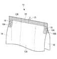
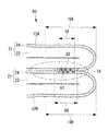
図1に示される本第1実施形態に係るガゼット袋10は、側部にガゼット部を有する袋であり、対向する一対の平面部12A,12Bと、これら平面部12A,12Bの両側に設けられ、側部のガゼット部として袋の内方に折り込まれる横ガゼット部14とを備える。First Embodiment
Hereinafter, a first embodiment of the present invention will be described.
The
なお、一対の平面部12A,12B及び一対の横ガゼット部14は、一枚の多層構造を有する樹脂等から形成されるフィルム状の積層体である積層フィルム21で形成されている。すなわち、本第1実施形態に係るガゼット袋10は、積層フィルム21を所定の位置で折ることで平面部12A,12B及び横ガゼット部14が形成される。また、平面部12A,12B及び一対の横ガゼット部14が形成される矩形状の積層フィルム21は、その両端部の内側表面同士が接合されて背貼ヒートシール部15が形成されている。 The pair of
図2に示されるように、積層フィルム21は、熱融着性を有する内表面層22と耐熱性を有する外表面層24が積層されている。すなわち、内表面層22がシーラント層であり、外表面層24が基材層である。
内表面層22を形成している樹脂の融点は、一例として170℃以下、外表面層24を形成している樹脂の融点は内表面層22を形成している樹脂の融点よりも高く、一例として250℃以上である。また、内表面層22と外表面層24との間に必要に応じて中間層である機能層が積層されていてもよい。As shown in FIG. 2, the
The melting point of the resin forming the
内表面層22として用いられるフィルムとしては、例えば、低密度ポリエチレン、中密度ポリエチレン、高密度ポリエチレン、線状低密度ポリエチレン等のポリエチレンやポリプロピレン等のポリオレフィン樹脂、又はこれらの混合樹脂、アイオノマー樹脂、エチレン−酢酸ビニル共重合体、エチレン−アクリル酸共重合体、エチレン−アクリル酸メチル共重合体、及びエチレン−メタクリル酸共重合体からなる群から選ばれる1種以上からなる未延伸フィルムが挙げられる。
なお、内表面層22の厚さは、30〜200μmが好ましい。Examples of the film used as the
The thickness of the
外表面層24として用いられるフィルムとしては、機械適性、印刷適性が良いフィルムが好ましい。例えば、ポリエステル系、ポリアミド系、ポリプロピレン系、ポリカーボネート系、ポリアセタール系等の合成樹脂からなるフィルムが挙げられる。これらのフィルムは、未延伸フィルムであってもよく、一軸方向又は二軸方向に延伸した延伸フィルムであってもよい。外表面層24として用いられるフィルムは、印刷適性の点から、一軸方向又は二軸方向に延伸した延伸フィルムを用いられることが好ましい。
具体的には、二軸延伸ポリエチレンテレフタレートフィルム、二軸延伸ポリアミドフィルム、二軸延伸ポリプロピレンフィルム等の延伸プラスチックフィルム等が挙げられる。また、必要に応じて合成紙、セロハン、紙、不織布等が用いられてもよい。
外表面層24に用いられるフィルムとして、蒸着層を設けた蒸着フィルムが用いられてもよい。蒸着層としては、例えば、アルミニウム、酸化珪素、酸化アルミニウム、酸化インジウム、酸化錫、酸化ジルコニウム、酸化マグネシウム等の無機物が挙げられる。
なお、外表面層24の厚さは、12〜25μmが好ましい。The film used as the
Specifically, oriented plastic films such as biaxially oriented polyethylene terephthalate film, biaxially oriented polyamide film, biaxially oriented polypropylene film, etc. may be mentioned. In addition, synthetic paper, cellophane, paper, non-woven fabric, and the like may be used as necessary.
As a film used for the
The thickness of the
機能層は、気体遮断性、機械的強靱性、耐屈曲性、耐突き刺し性、耐衝撃性、耐磨耗性、耐寒性、耐熱性、耐薬品性等、要求される機能に応じて適宜選択できる。
機能層に用いられるフィルムとしては、例えば、アルミニウム、鉄、銅、錫等の金属箔、ポリエチレンテレフタレート、ポリアミド、ポリ塩化ビニル、ポリカーボネート、ポリビニルアルコール、エチレン−酢酸ビニル共重合体ケン化物等のフィルム、又はこれらにポリ塩化ビニリデンを塗工したフィルム若しくはアルミニウム、酸化珪素、酸化アルミニウム、酸化インジウム、酸化錫、酸化ジルコニウム、酸化マグネシウム等の無機物を蒸着したフィルム、ポリ塩化ビニリデン等のフィルムや、断熱性を有する不織布や発泡フィルムが挙げられる。
機能層は、1層であってもよく、2層以上であってもよい。
なお、機能層の厚さは、ガゼット袋10に要求される機能を満たすことができる厚さであればよく、6〜20μmが好ましい。The functional layer is appropriately selected according to the required function such as gas barrier property, mechanical toughness, bending resistance, puncture resistance, impact resistance, abrasion resistance, cold resistance, heat resistance, chemical resistance, etc. it can.
The film used for the functional layer is, for example, a metal foil of aluminum, iron, copper, tin or the like, a film of polyethylene terephthalate, polyamide, polyvinyl chloride, polycarbonate, polyvinyl alcohol, saponified ethylene-vinyl acetate copolymer, etc. Or films coated with polyvinylidene chloride or films deposited with inorganic substances such as aluminum, silicon oxide, aluminum oxide, indium oxide, indium oxide, tin oxide, zirconium oxide, magnesium oxide, films such as polyvinylidene chloride, Non-woven fabrics and foamed films are included.
The functional layer may be a single layer or two or more layers.
In addition, the thickness of a functional layer should just be the thickness which can satisfy | fill the function requested | required of the
図1に示したように、平面部12Aの側部と横ガゼット部14の側部とは、第1接合部である側部ヒートシール部16Aによって内側表面同士で接合されている。また、平面部12Bの側部と横ガゼット部14の他の側部とは、第2接合部である側部ヒートシール部16Bによって内側表面同士で接合されている。図3は、ガゼット袋10に側部ヒートシール部16A,16Bが形成された状態が示される。
なお、図1,3から明確なように、側部ヒートシール部16A,16Bは各々異なる領域を接合している。すなわち、側部ヒートシール部16Bは、側部ヒートシール部16Aとは異なる領域で内表面層22同士を接合する。この異なる領域とは、換言すると、側部ヒートシール部16Aによって接合された横ガゼット部14の側部に対向する横ガゼット部14の他の側部(側部ヒートシール部16B)である。
なお、この対抗する側部ヒートシール部16Aと側部ヒートシール部16Bとが、後述する第3接合部(閉止シール部18)によって外表面層同士24で、超音波シールによって接合される。
図1,3では、側部ヒートシール部16A,16Bによる接合が、平面部12と横ガゼット部14の側部におけるガゼット袋10の上端近辺や下端近辺(図示せず)に行われている。しかし、これに限らず、側部ヒートシール部16A,16Bによる接合が平面部12と横ガゼット部14の側部におけるガゼット袋10の上端から下端に至るまで行われていても良い。As shown in FIG. 1, the side portion of the
As is clear from FIGS. 1 and 3, the side
The opposing side
In FIGS. 1 and 3, bonding by the side
側部ヒートシール部16A,16Bの接合は、例えばヒートシールが用いられる。ヒートシールによる接合は、加熱されたヒートシールバーを積層フィルム21に押し当てた後、冷却された冷却バーを押し当てるという熱板シールを用いた接合である。なお、外表面層24は、耐熱性を有しているため、側部ヒートシール部16A,16Bを接合するヒートシールにより接合されることはない。
側部ヒートシール部16A,16Bの接合として、この他にインパルスシール等、他の方法が用いられても良い。また、積層フィルム21を構成する層にポリ塩化ビニル層や金属箔層を含む場合には、高周波シールによる接合とすることができる。さらに、接着剤による接合等、超音波シールを除く他の接合方法が用いられても良い。For example, a heat seal is used to join the side
Other methods such as impulse sealing may be used to join the side
本第1実施形態に係るガゼット袋10は、一枚の積層フィルム21が折られることで一対の平面部12A,12Bと一対の横ガゼット部14が形成されているため、袋として機能するためには本来、側部ヒートシール部16A,16Bを必要としない。しかしながら、詳細を後述するように、ガゼット袋10内への屑の混入を防止して、ガゼット袋10の上部において横ガゼット部14の開きを第3接合部によって閉じるため、側部ヒートシール部16A,16Bによる接合が行われる。
なお、本第1実施形態に係るガゼット袋10は、積層フィルム21が折られて平面部12と横ガゼット部14とされており、側部ヒートシール部16A,16Bはガゼット袋10の上端近辺のみに形成されている。このため、利用者が手で持つ部分には硬い側部ヒートシール部16A,16Bは形成されておらず、手で持った際に感じる痛みが緩和される。しかしながら、このように平面部12A,12Bと横ガゼット部14が一枚の積層フィルム21を折ることで区画して設けられたガゼット袋10は、横ガゼット部14に貫通孔を設けて貫通孔の位置を合わせることが困難である。このため、横ガゼット部14の開きを閉じるためには、第1接合部と第2接合部の外側表面同士を超音波シールによって第3接合部にて接合する方法が適している。
一方、平面部12と横ガゼット部14が別々の積層フィルム21で形成され、それぞれの側部をそろえて側部ヒートシール部16A,16Bにより接合される場合は、平面部12と横ガゼット部14の側部におけるガゼット袋10の上端から下端に至るまで連続した側部ヒートシール部16A,16Bにより密閉する必要があり、ガゼット袋10の左右端部が硬くなってしまう。The
In the
On the other hand, when the flat portion 12 and the lateral
上述のように、本第1実施形態に係るガゼット袋10は、側部ヒートシール部16Aと側部ヒートシール部16Bとが、第3接合部である閉止シール部18によって横ガゼット部14の外側表面同士で接合されている。閉止シール部18の接合は、例えば図1に示されるように横ガゼット部14の上端近辺や下端近辺(図示せず)にて行われている。本第1実施形態に係る閉止シール部18は、側部ヒートシール部16に比べてその範囲が狭い。すなわち、閉止シール部18は、全体が側部ヒートシール部16の領域に含まれている。
閉止シール部18が形成されていないと、横ガゼット部14は外側表面同士が離間して開いた状態となってしまう。すなわち、閉止シール部18によって、横ガゼット部14の上端部や下端部の開きが閉じられている。As described above, in the
If the
閉止シール部18の接合は、内部加熱である超音波シールにより行われる。横ガゼット部14の外側表面である外表面層24は、耐熱性を有しており、ヒートシール等の外部加熱による接合が適さないためである。
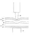
超音波シールは、図4の例に示されるように、接合させる箇所が、超音波シール機30と基台31とで挟まれることで行われる。そして、接合させる箇所に超音波シール機30が押し当てられ、超音波によって、対向する積層フィルム21,21間に微振動が発生し、この微振動による摩擦熱を用いて接合が行われる。Bonding of the
As shown in the example of FIG. 4, the ultrasonic sealing is performed by the portion to be joined being sandwiched between the
本第1実施形態に係るガゼット袋10の閉止シール部18を形成するために、超音波シール機30と基台31とでガゼット袋10の側部を挟み、超音波シールが施される。その際、平面部12と横ガゼット部14の内側表面同士は、内表面層22同士で側部ヒートシール部16A,16Bにおいてすでに接合されている。このため、超音波が発せられても、この部分では内表面層22同士に相対移動が生じず、擦れ合うことはない。一方、横ガゼット部14の外側表面同士において外表面層24同士のみが擦れ合い、擦れ合うことで摩擦熱が選択的に生じるので、外表面層24同士が接合され、閉止シール部18が形成される。
超音波シールによる接合は、接合させる2面を擦れ合わせるため屑が生じる場合がある。しかしながら、閉止シール部18による接合によって屑が生じる部分は、図5に示されるように、横ガゼット部14の外側表面同士が擦れ合わされる部分である。この閉止シール部18が形成される部分は、ガゼット袋10の外側である。このため、超音波シールによる接合によって屑が生じても、外側表面であるため袋内に屑が混入することはない。In order to form the
Bonding by ultrasonic sealing may generate scraps because the two surfaces to be bonded are rubbed together. However, as shown in FIG. 5, the portion where debris is generated by the bonding by the
ここで、上述した図4の例は、内表面層22であるシーラント層同士を超音波シールによって接合させる例である。このような接合の場合、内表面層22同士が擦れ合い、袋内に屑が生じる。すなわち、仮に側部ヒートシール部16A,16Bによる接合が行われることなく、超音波シールを用いた閉止シール部18による接合のみが行われると、横ガゼット部14は閉じられるものの、平面部12と横ガゼット部14の内表面層22同士も擦れ合い、ガゼット袋10内に屑が生じる恐れがある。 Here, the example of FIG. 4 mentioned above is an example which joins sealant layers which are inner surface layers 22 by ultrasonic sealing. In the case of such bonding, the inner surface layers 22 rub against each other to generate waste in the bag. That is, if bonding is not performed by the side
しかし上述したように、本第1実施形態では、閉止シール部18によって横ガゼット部14を閉じる際に、側部ヒートシール部16A,16Bがすでに接合されているため、この部分では内表面層22同士が擦れ合うことはなく、屑も生じない。従って、本第1実施形態に係るガゼット袋10は、横ガゼット部14を閉じるために超音波シールによる接合を行っても、フィルム片や屑が袋内に混入することが防止される。 However, as described above, in the first embodiment, the side
次に、本第1実施形態に係るガゼット袋10の製造方法について説明する。
なお、本第1実施形態では、上述したように、外表面層24である基材層と内表面層22であるシーラント層を有する一枚の積層フィルム21によって、一対の平面部12A,12Bと一対の横ガゼット部14が形成される。Next, a method of manufacturing the
In the first embodiment, as described above, the pair of
第1工程:シーラント層がガゼット袋10の内側表面となるように、フィルムロールから繰り出された積層フィルム21の両端部のシーラント層同士が接合される。この接合によって、背貼ヒートシール部15が形成され、積層フィルム21は筒状部材とされる。背貼ヒートシール部15の接合は、一例としてヒートシールにより行われる。 First step: The sealant layers at both ends of the
第2工程:横ガゼット部14となる領域が、筒状部材の内方に折り込まれる。 Second step: The area to be the
第3工程:筒状部材の上部の開放端部が、一例としてヒートシールによって接合され、開放端シール部20が形成される。 Third step: The upper open end of the tubular member is joined by heat sealing, as an example, to form an
第4工程:筒状部材の上部や下部における平面部12の側部において、側部ヒートシール部16A,16Bが形成される(図3参照)。 Fourth step: side
第5工程:側部ヒートシール部16A,16Bの領域内、すなわち側部ヒートシール部16A,16Bの領域に含まれるように、閉止シール部18が形成され、横ガゼット部14が閉じられる(図1参照)。 Fifth step: the closing
なお、第2工程の後に第4工程が行われ、第4工程及び第5工程が行われた後に第3工程が行われても良い。 The fourth step may be performed after the second step, and the third step may be performed after the fourth and fifth steps are performed.
以上説明したように、本第1実施形態に係るガゼット袋10は、対向する一対の平面部12A,12Bと、袋の内方に折り込まれる横ガゼット部14とで形成される。そして、ガゼット袋10は、平面部12Aの側部と横ガゼット部14の側部とを、内側表面同士で接合した側部ヒートシール部16A,平面部12Bの側部と横ガゼット部14の他の側部とを、内側表面同士で接合した側部ヒートシール部16Bを備える。さらに、ガゼット袋10は、側部ヒートシール部16Aと側部ヒートシール部16Bとを横ガゼット部14の外側表面同士で、超音波シールによって接合した閉止シール部18を備える。 As explained above, the
これにより、本第1実施形態に係るガゼット袋10は、超音波シールによって横ガゼット部14の外側表面同士の接合を行っても、袋の内側表面同士は側部ヒートシール部16A,16Bによってすでに接合されているため、ガゼット袋10の内側表面同士は擦れ合わず屑が発生しない。従って、本第1実施形態に係るガゼット袋10は、横ガゼット部14を閉じる工程においてフィルム片や屑が袋内に混入することを防止できると共に、簡易に横ガゼット部14を閉じることができる。また、横ガゼット部14を有するガゼット袋10では、外観に優れ、誤ってガゼット袋10を落下させてしまった場合でも、破袋の発生が抑制される。 Thereby, even if the
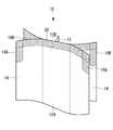
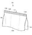
図6は、第1実施形態の他の例である各部が別々の積層フィルム21で形成される場合のガゼット袋50の上部を示した斜視図である。すなわち、図6に示されるガゼット袋50は、一対の平面部12A,12Bが各々一枚の積層フィルム21で形成され、一対の横ガゼット部14が各々一枚の積層フィルム21で形成されている。
この形態の場合、図6に示されるように、側部ヒートシール部16A,16Bは、ガゼット袋50の上部から下部にかけて形成されている。FIG. 6 is a perspective view showing the upper part of the
In the case of this embodiment, as shown in FIG. 6, the side
図7は、図6に対応した側部ヒートシール部16A,16Bを部分拡大して示した横断面図である。
図7に示されるように、ガゼット袋50は、各部が別々の積層フィルム21で形成されているため、横ガゼット部14の端部は切断面21Aとされており、一枚の積層フィルム21によって形成されるガゼット袋10のように曲面とされていない(図5参照)。FIG. 7 is a cross-sectional view showing the side
As shown in FIG. 7, since each portion of the
また、平面部12Aと一対の横ガゼット部14とが一枚の積層フィルム21で形成され、平面部12Bがそれとは異なる積層フィルム21で形成されてもよい。 Alternatively, the
また、図1及び図6の第1実施形態では、第1接合部、第2接合部として側部ヒートシール部16A,16Bに閉止シール部18を形成した例を示したが、これに限らず、図8に示されるガゼット袋60のように開放端シール部20の側部を第1接合部、第2接合部とみなし、開放端シール部20に閉止シール部18が形成されてもよい。なお、図8の例では、第3接合部である閉止シール部18を設けた第1接合部及び第2接合部の領域が、開放端シール部20と重なるように設けられている。 Moreover, although the example which formed the
〔第2実施形態〕
以下、本発明の第2実施形態について説明する。Second Embodiment
Hereinafter, a second embodiment of the present invention will be described.
図9は、本第2実施形態に係るガゼット袋70の正面図である。なお、図9における図1と同一の構成部分については図1と同一の符号を付して、その説明を省略する。
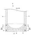
本第2実施形態に係るガゼット袋70は、一対の平面部12A,12B及び底ガゼット部40によって形成される。底ガゼット部40は、一対の平面部12A,12Bの下部において、一対の平面部12A,12Bの間に内方に折り込まれて形成されている。なお、ハッチングで示される領域は、ガゼット袋70を形成する積層フィルム21が接合されている領域である。FIG. 9 is a front view of the
The
平面部12A,12Bと底ガゼット部40とは、ガゼット袋70の下部において、内側表面同士が下部ヒートシール部42によって接合されている。
また、ガゼット袋70の側部において、平面部12A、12Bの側部の相対する内側表面同士は側部ヒートシール部16によって接合されており、平面部12Aの側部と底ガゼット部40の側部、平面部12Bの側部と底ガゼット部40の他の側部のそれぞれ相対する内側表面同士は、側部ヒートシール部16A,16Bによって接合されている。ここで側部ヒートシール部16と側部ヒートシール部16A、側部ヒートシール部16と側部ヒートシール部16Bはそれぞれ連続したものである。なお、平面部12Aの側部と底ガゼット部40の側部の内側表面同士の接合である側部ヒートシール部16Aは第1接合部であり、平面部12Bの側部と底ガゼット部40の他の側部の内側表面同士の接合である側部ヒートシール部16Bは第2接合部である。また、下部ヒートシール部42は側部ヒートシール部16A,16Bと一体とした舟型ヒートシール部としてもよく、舟型ヒートシール部には、下部ヒートシール部42内で接合されない領域である未シール部44が適宜設けられている。下部ヒートシール部42及び側部ヒートシール部16A,16Bは、共に例えばヒートシールによって接合される。ヒートシールによる接合は、第1実施形態と同様であるため、説明を省略する。At the lower part of the
Further, on the side of the
ここで、側部ヒートシール部16A,16Bによる接合のみを行った状態では、側部ヒートシール部16A,16Bにおいて底ガゼット部40は、開いた状態となっている。
開いた状態を閉じることによって自立性を持たせるために、側部ヒートシール部16A,16Bの領域に含まれるように、底ガゼット部40の外側表面同士が、超音波シールによる接合である閉止シール部18によって接合される。なお、閉止シール部18は、第3接合部である。超音波シールによる接合は、第1実施形態と同様であるため、説明を省略する。
そして、閉止シール部18によって底ガゼット部40の外側表面同士を閉じても、側部ヒートシール部16A,16Bがすでに接合されているため、この部分では平面部12Aと底ガゼット部40、及び平面部12Bと底ガゼット部40のそれぞれ内側表面同士は擦れ合うことがない。従って、本第2実施形態に係るガゼット袋70は、底ガゼット部40を閉じるために超音波シールによる接合を行っても、フィルム片や屑が袋内に混入することが防止される。Here, in the state in which only the bonding by the side
In order to make the self-sustaining ability by closing the open state, the outer surfaces of the
And, even if the outer surfaces of the
なお、閉止シール部18は、側部ヒートシール部16A,16Bと底ガゼット部40が重なる位置において、左右一箇所ずつ設けられればよいが、これに限らず、例えば、ガゼット袋70のサイズに応じて、図9に示されるようにガゼット袋70の縦方向に閉止シール部18が複数箇所設けられてもよい。 In addition, although the
以上説明したように、本第2実施形態に係るガゼット袋70は、平面部12A,12Bと底ガゼット部40とを接合する側部ヒートシール部16A,16Bの領域に含まれるように、底ガゼット部40の外側表面同士が、閉止シール部18によって接合される。 As described above, the
これにより、本第2実施形態に係るガゼット袋70は、超音波シールによって閉止シール部18の接合が行われても、袋の内側となる平面部12Aと底ガゼット部40、及び平面部12Bと底ガゼット部40の内側表面同士は、側部ヒートシール部16A,16Bにおいてすでに接合されているため、この内側表面同士は擦れ合うことがなく、屑が発生しない。従って、本第2実施形態に係るガゼット袋70は、底ガゼット部40を閉じる工程において屑がガゼット袋70内に混入することが防止されると共に、簡易に底ガゼット部40が閉じられる。そのため、底ガゼット部40を有するガゼット袋70では、自立性を向上させることができる。
〔第3実施形態〕
以下、本発明の第3実施形態について説明する。As a result, in the
Third Embodiment
Hereinafter, a third embodiment of the present invention will be described.
図10は、本第3実施形態に係るガゼット袋80の上部を示した斜視図である。なお、図10における図3と同一の構成部分については図3と同一の符号を付して、その説明を省略する。 FIG. 10 is a perspective view showing the upper part of the
本第3実施形態に係るガゼット袋80は、閉止シール部18の接合面に凹凸形状82が形成される。
そこで、本第3実施形態に係るガゼット袋80は、図10に示されるように、横ガゼット部14の外側表面の閉止シール部18で接合される予定位置を含む領域(以下「凹凸形成領域」という。)84に凹凸形状82が形成される。なお、凹凸形成領域84は、閉止シール部18と重なるように設けられるため、側部ヒートシール部16A,16Bとも重なるように設けられることとなる。In the
Therefore, as shown in FIG. 10, the
また、図10の例では、凹凸形状82が形成される凹凸形成領域84が、横ガゼット部14の側部において略上部から下部まで一様に設けられている。しかし、これに限らず、凹凸形成領域84は、少なくとも閉止シール部18で接合される予定位置を含めばよく、横ガゼット部14の側部の一部にのみ設けられてもよい。
また、図10の例では、凹凸形成領域84が閉止シール部18で接合される外側表面の両側に設けられるが、これに限らず、凹凸形成領域84は閉止シール部18で接合される外側表面(側部ヒートシール部16A,16B)の何れか一方にのみ設けられてもよい。Moreover, in the example of FIG. 10, the uneven |
Further, in the example of FIG. 10, although the concavo-convex forming
凹凸形状82は、一例として、粗面又は切れ目等である。
粗面は、例えば微細な点状の傷痕であり、この傷痕が等間隔又は不規則(ランダム)に多数形成される。
切れ目は、線状の傷痕であり、この傷痕が連続(一文字状)又は不連続(ミシン目状)、かつ並列に多数形成される。より具体的には、線状の傷痕が横ガゼット部14の横方向に形成され、これが縦方向に並列に多数形成されてもよいし、線状の傷痕が横ガゼット部14の縦方向に形成され、これが横方向に並列に多数形成されてもよい。また、切れ目として、例えば、十字状やX字状のものが複数形成されてもよい。
なお、凹凸形状82は、上述した粗面又は切れ目以外の他の形状でもよい。The
The rough surface is, for example, a fine point-like scar, and a large number of the scars are formed at equal intervals or irregularly (randomly).
The cuts are linear scars, and the scars are formed in a large number in a continuous (one-letter shape) or discontinuous (perforated shape) in parallel. More specifically, linear scars may be formed in the lateral direction of the
In addition, the concavo-
粗面は、例えばやすり、砥粒または表面に凹凸加工を施したロール等を凹凸形成領域84に押圧することによって形成される。また、切れ目は、例えば金属製の針や刃等を押圧することによって形成される。さらに、これに限らず、粗面や切れ目は、炭酸ガスレーザ等を用いたレーザ加工等やワイヤブラシの使用等、他の方法によって形成されてもよい。 The rough surface is formed, for example, by pressing a file, an abrasive, a roll having a surface with irregularities, or the like to the asperity-forming
このように、本第3実施形態に係るガゼット袋80は、閉止シール部18の接合面に凹凸形状82が形成された後に閉止シール部18に対して超音波シールによる接合が行われることとなる。
閉止シール部18の接合面に凹凸形状82が形成されることによって、閉止シール部18の表面積が増え、超音波シールが行われることによる摩擦抵抗が大きくなる。従って、本第3実施形態に係るガゼット袋80は、凹凸形状82を形成しない場合に比較して、閉止シール部18の接合強度はより高められ、接合した閉止シール部18がその後剥離することを抑制できる。As described above, in the
By forming the concavo-
また、凹凸形状82は、外表面層24を貫通してもよいし、貫通しなくてもよい。
図11は、第3実施形態に係る側部ヒートシール部16A,16Bを部分拡大して示した横断面図であり、外表面層24を貫通する凹凸形状82が形成された閉止シール部18を図示している。In addition, the
FIG. 11 is a cross-sectional view showing the side
凹凸形状82が外表面層24を貫通し内表面層22まで到達すると、図11の矢印で示されるように、内表面層22(シーラント層)を形成する樹脂が凹凸形状82による貫通孔から外表面層24へ染み出す。このシーラント層を形成する樹脂は熱融着性を有している。このため、閉止シール部18の接合が行われる際に、外表面層24に染み出した樹脂も摩擦熱による接合(熱融着)に寄与することとなり、閉止シール部18の接合強度は更に高められることとなる。 When the concavo-
なお、凹凸形状82を形成する各傷痕の幅(径)が大きい程、染み出す内表面層22の樹脂の量も多くなり、樹脂の熱融着による接合強度が高まるものの、凹凸形状82による接合強度が相対的に弱まる。一方、凹凸形状82を形成する各傷痕の幅が小さい程、染み出す樹脂の量も少なくなり、樹脂の熱融着による接合強度が弱まるものの、凹凸形状82による接合強度が相対的に高まる。
このため、凹凸形状82を外表面層24に対して貫通させる場合には、樹脂の熱融着による接合強度と凹凸形状82による接合強度とのバランスを考慮して傷痕の幅が決定されることが好ましい。The larger the width (diameter) of each scar forming the concavo-
Therefore, in the case where the
また、ガゼット袋80を形成する積層フィルム21が外表面層24と内表面層22との間に熱融着性を有しない中間層である機能層を有している場合、凹凸形状82は、外表面層24及び中間層を貫通し、貫通孔が内表面層22に達してもよい。 Further, in the case where the
以上、本発明を、上記各実施形態を用いて説明したが、本発明の技術的範囲は上記実施形態に記載の範囲には限定されない。発明の要旨を逸脱しない範囲で上記各実施形態に多様な変更又は改良を加えることができ、該変更又は改良を加えた形態も本発明の技術的範囲に含まれる。 As mentioned above, although this invention was demonstrated using said each embodiment, the technical scope of this invention is not limited to the range as described in the said embodiment. Various changes or improvements can be added to the above-described embodiments without departing from the scope of the invention, and a mode in which the changes or improvements are added is also included in the technical scope of the present invention.
例えば、上記各実施形態では、閉止シール部18の全体が側部ヒートシール部16A,16B又は下部ヒートシール部42の領域に含まれる形態について説明したが、本発明は、これに限定されるものではなく、閉止シール部18の一部が側部ヒートシール部16A,16B又は下部ヒートシール部42Bの領域に含まれる形態としてもよい。For example, in the above embodiments, the whole of the
また、上記各実施形態では、側部ヒートシール部16A,16Bに閉止シール部18が複数設けられてもよい。 Further, in each of the above embodiments, a plurality of closing
また、上記各実施形態では、ガゼット袋10,50,60,70,80の外側表面がヒートシール等で接合可能な熱融着性を有していてもよい。 In each of the above embodiments, the outer surfaces of the
また、上記各実施形態では、ガゼット袋10,50,60,70,80に内容物を外部へ注出する注出口が設けられてもよい。 In the above embodiments, the
10,50,60,70,80 ガゼット袋
12 平面部
14 横ガゼット部
16A 側部ヒートシール部
16B 側部ヒートシール部
18 閉止シール部
21 積層フィルム
22 内表面層
24 外表面層
82 凹凸形状10, 50, 60, 70, 80 gusset bag 12
Claims (7)
Translated fromJapanese袋の内方に折り込まれるガゼット部と、
前記平面部の側部と前記ガゼット部の側部とを、内側表面同士で接合した第1接合部と、
他の前記平面部の側部と前記ガゼット部の他の側部とを、内側表面同士で接合した第2接合部と、
前記第1接合部と前記第2接合部とを前記ガゼット部の外側表面同士で、超音波シールによって接合した第3接合部と、
を備え、
前記第3接合部はガゼット袋の端部と接しないガゼット袋。A pair of opposing flat portions,
The gusset, which is folded inside the bag,
A first joint in which the side portions of the flat portion and the side portions of the gusset portion are joined at inner surfaces;
A second joint in which the side portion of the other flat portion and the other side portion of the gusset portion are joined at inner surfaces;
A third bonding portion in which the first bonding portion and the second bonding portion are bonded by ultrasonic sealing at outer surfaces of the gusset portions;
Equippedwith
The third joint portion is a gusset bag not in contact with the end of the gusset bag.
前記平面部の側部と前記ガゼット部の側部とを、第1接合部によって内側表面同士で接合し、
他の前記平面部の側部と前記ガゼット部の他の側部とを、第2接合部によって内側表面同士で接合し、
前記第1接合部と前記第2接合部とを前記ガゼット部の外側表面同士で、超音波シールによって接合して前記ガゼット袋の端部と接しないように第3接合部を形成するガゼット袋の製造方法。A manufacturing method of a gusset bag comprising a pair of opposed flat parts and a gusset part which is folded inward of the bag,
Bonding the side portions of the flat portion and the side portions of the gusset portion together at the inner surfaces by the first bonding portion;
The other side of the flat portion and the other side of the gusset are joined at the inner surfaces by a second joint,
Agusset bag for joining the first joint portion and the second joint portion by ultrasonic sealing at outer surfaces of the gusset portions and forming a third joint portionso as not to be in contact with the end portion of the gusset bag Production method.
前記第1層同士を第1接合部で接合し、
前記第1接合部とは異なる領域で前記第1層同士を第2接合部で接合し、
前記第1接合部と前記第2接合部とを前記第2層同士で、超音波シールによって接合して前記積層体の端部と接しないように第3接合部を形成する積層体の接合方法。A method of bonding a laminate, in which a first layer having heat fusion properties and a second layer having heat resistance are stacked, and the second layers are bonded to each other.
Bonding the first layers together at a first bonding portion;
Bonding the first layers together in a second bonding portion in a region different from the first bonding portion;
The joining method of a layered product which joins the 1st junction part and the 2nd junction part with the 2nd layers by ultrasonic seal, and forms the 3rd junction partso that it may not contact with the end of the layered product. .
Applications Claiming Priority (3)
| Application Number | Priority Date | Filing Date | Title |
|---|---|---|---|
| JP2014011320 | 2014-01-24 | ||
| JP2014011320 | 2014-01-24 | ||
| PCT/JP2015/051934WO2015111736A1 (en) | 2014-01-24 | 2015-01-23 | Gusset bag, method for producing gusset bag, and method for joining laminate |
Publications (2)
| Publication Number | Publication Date |
|---|---|
| JPWO2015111736A1 JPWO2015111736A1 (en) | 2017-03-23 |
| JP6537979B2true JP6537979B2 (en) | 2019-07-03 |
Family
ID=53681532
Family Applications (1)
| Application Number | Title | Priority Date | Filing Date |
|---|---|---|---|
| JP2015559155AActiveJP6537979B2 (en) | 2014-01-24 | 2015-01-23 | Gusset bag, method of manufacturing gusset bag, and method of joining laminates |
Country Status (5)
| Country | Link |
|---|---|
| US (1) | US20170008675A1 (en) |
| EP (1) | EP3098177B1 (en) |
| JP (1) | JP6537979B2 (en) |
| CN (1) | CN105934391B (en) |
| WO (1) | WO2015111736A1 (en) |
Cited By (1)
| Publication number | Priority date | Publication date | Assignee | Title |
|---|---|---|---|---|
| US12011898B2 (en) | 2020-07-20 | 2024-06-18 | Totani Corporation | Bag making method |
Families Citing this family (13)
| Publication number | Priority date | Publication date | Assignee | Title |
|---|---|---|---|---|
| JP6688666B2 (en)* | 2016-04-15 | 2020-04-28 | 株式会社細川洋行 | Gazette bag and method of manufacturing gazette bag |
| JP2018030589A (en)* | 2016-08-22 | 2018-03-01 | 凸版印刷株式会社 | Packaging container and manufacturing method thereof |
| JP1591558S (en)* | 2017-04-27 | 2017-11-20 | ||
| WO2020038272A1 (en)* | 2018-08-18 | 2020-02-27 | 中山市太力家庭用品制造有限公司 | Anti-tear structure for vacuum compression bag comprising bag body having y-shaped structure and vacuum compression bag containing said anti-tear structure |
| DE102018214127A1 (en)* | 2018-08-21 | 2020-02-27 | Huhtamaki Flexible Packaging Germany Gmbh & Co. Kg | Foil packaging with a combination heat-sealing zone formed by different sealing processes and sealing tool therefor |
| AU2020221574B2 (en)* | 2019-02-11 | 2025-03-06 | The Glad Products Company | Thermoplastic bags with duplicative seals |
| US11383877B2 (en)* | 2019-05-09 | 2022-07-12 | Innovative Packaging Solutions, Inc. | Heavy duty pack and method of manufacturing |
| CN113939460A (en)* | 2019-06-28 | 2022-01-14 | 玛鲁哈日鲁株式会社 | Frozen food pouch product |
| WO2021220591A1 (en)* | 2020-04-28 | 2021-11-04 | 東洋製罐株式会社 | Pouch and filling method |
| KR102613868B1 (en)* | 2021-02-18 | 2023-12-14 | 오리히로 엔지니어링 가부시키가이샤 | Vertical pouch manufacturing filling packaging machine, manufacturing method of film packaging pouch with contents, film packaging pouch with contents |
| JPWO2022215625A1 (en)* | 2021-04-08 | 2022-10-13 | ||
| JP7190762B2 (en)* | 2021-05-20 | 2022-12-16 | 株式会社エフテック | Fungus bed cultivation bag and method for producing fungus bed cultivation bag |
| JP2025130971A (en)* | 2024-02-28 | 2025-09-09 | 株式会社細川洋行 | Packaging bag and its manufacturing method |
Family Cites Families (29)
| Publication number | Priority date | Publication date | Assignee | Title |
|---|---|---|---|---|
| US3434652A (en)* | 1966-07-26 | 1969-03-25 | Diamond Shamrock Corp | Self-supporting plastic container and method of making same |
| JPS6055793U (en)* | 1983-09-27 | 1985-04-18 | 株式会社東芝 | rotary compressor |
| FR2587935B1 (en)* | 1985-09-30 | 1990-11-09 | Cantenot Francois | PROCESS FOR THE MANUFACTURE OF BELLOWS BAGS FROM A COMPLEX FILM CONSISTING OF TWO ELEMENTARY FILMS OF DIFFERENT PLASTIC MATERIALS JOINED BY APPLYING ULTRA-SOUNDS |
| JP3079185B2 (en)* | 1990-01-11 | 2000-08-21 | 藤森工業株式会社 | Packaging bag sealing method |
| JPH078430Y2 (en) | 1990-02-09 | 1995-03-01 | 大日本印刷株式会社 | Gusset bag |
| JP2669214B2 (en)* | 1991-09-13 | 1997-10-27 | 凸版印刷株式会社 | Ultra low density polyethylene film with improved heat sealability |
| JPH08324520A (en)* | 1995-05-30 | 1996-12-10 | Fujimori Kogyo Kk | How to seal the packaging bag |
| US6120183A (en)* | 1997-08-19 | 2000-09-19 | Technical Developers, Inc. | Container and method of manufacturing same from a web of flexible material |
| JPH11124148A (en)* | 1997-10-17 | 1999-05-11 | Tdk Corp | Bag-shaped package and its manufacture |
| JP4282179B2 (en)* | 1999-09-30 | 2009-06-17 | 四国化工機株式会社 | Ultrasonic sealing device |
| US6716499B1 (en)* | 2000-06-08 | 2004-04-06 | Cryovac, Inc. | Moisture/oxygen barrier bag |
| US20040025476A1 (en)* | 2002-04-10 | 2004-02-12 | Oliverio Frank G. | Stand-up pouch forming, filling and sealing |
| JP3460999B1 (en)* | 2002-12-17 | 2003-10-27 | 株式会社細川洋行 | Gazette bag |
| DE10356431A1 (en)* | 2003-11-29 | 2005-06-30 | Herrmann Ultraschalltechnik Gmbh & Co. Kg | Device for welding multilayer laminates |
| SE528141C2 (en)* | 2004-06-09 | 2006-09-12 | Eco Lean Res & Dev As | Method and apparatus for providing sealing and use of such a method |
| GB2418905A (en)* | 2004-10-06 | 2006-04-12 | Safapac | Collapsible container for chemicals |
| DE112006000289A5 (en)* | 2005-03-29 | 2007-12-13 | Huhtamaki Ronsberg, Zweigniederlassung Der Huhtamaki Deutschland Gmbh & Co. Kg | Film packaging and in particular film bag, and method for producing and sealing tool |
| US20070189644A1 (en)* | 2006-02-14 | 2007-08-16 | Ppi Technologies, Inc. | Apparatus and method of forming a flexible pouch with improved side seam |
| JP2008273545A (en)* | 2007-04-26 | 2008-11-13 | Toppan Printing Co Ltd | Ship bottom type gusset packaging bag |
| US8259738B2 (en)* | 2007-05-01 | 2012-09-04 | Net Navigation Systems, Llc | Channel service manager with priority queuing |
| JP2009090987A (en) | 2007-10-04 | 2009-04-30 | Toppan Printing Co Ltd | Self-supporting packaging bag |
| US20090233025A1 (en)* | 2008-03-13 | 2009-09-17 | Cvancara Lance L | Multi-Seal Method Capable Structures for Gusseted Flexible Containers |
| BRPI0910875B8 (en)* | 2008-03-27 | 2021-06-22 | Mannkind Corp | dry powder inhalation system |
| JP2009241949A (en)* | 2008-03-31 | 2009-10-22 | Dainippon Printing Co Ltd | Self-supporting bag with anti-slippage function |
| JP5335365B2 (en)* | 2008-10-24 | 2013-11-06 | 朋和産業株式会社 | Rice cooked food packaging material and ultrasonic sealing method |
| MX358565B (en)* | 2009-10-08 | 2018-08-24 | Illinois Tool Works Inc Star | Carton with plastic reclosable header. |
| JP5400585B2 (en)* | 2009-11-27 | 2014-01-29 | ユニ・チャーム株式会社 | Absorbent package |
| JP6002982B2 (en)* | 2011-08-31 | 2016-10-05 | 株式会社フジシール | Pouch container |
| JP2017217764A (en)* | 2016-06-03 | 2017-12-14 | 株式会社細川洋行 | Packaging bag sealing method and packaging bag |
- 2015
- 2015-01-23JPJP2015559155Apatent/JP6537979B2/enactiveActive
- 2015-01-23EPEP15740753.7Apatent/EP3098177B1/enactiveActive
- 2015-01-23WOPCT/JP2015/051934patent/WO2015111736A1/enactiveApplication Filing
- 2015-01-23CNCN201580005357.1Apatent/CN105934391B/enactiveActive
- 2015-01-23USUS15/113,232patent/US20170008675A1/ennot_activeAbandoned
Cited By (1)
| Publication number | Priority date | Publication date | Assignee | Title |
|---|---|---|---|---|
| US12011898B2 (en) | 2020-07-20 | 2024-06-18 | Totani Corporation | Bag making method |
Also Published As
| Publication number | Publication date |
|---|---|
| US20170008675A1 (en) | 2017-01-12 |
| JPWO2015111736A1 (en) | 2017-03-23 |
| CN105934391B (en) | 2018-12-25 |
| WO2015111736A1 (en) | 2015-07-30 |
| CN105934391A (en) | 2016-09-07 |
| EP3098177B1 (en) | 2018-10-24 |
| EP3098177A4 (en) | 2017-08-23 |
| EP3098177A1 (en) | 2016-11-30 |
Similar Documents
| Publication | Publication Date | Title |
|---|---|---|
| JP6537979B2 (en) | Gusset bag, method of manufacturing gusset bag, and method of joining laminates | |
| JP5593165B2 (en) | Gazette bag, gusset bag with mouth member, and manufacturing method thereof | |
| JPWO2009090930A1 (en) | Easy-open packaging bag | |
| JP2013049458A (en) | Gusset bag and gusset bag with mouth member, and method for manufacturing them | |
| JP2015199534A (en) | Packaging bag and manufacturing method of the same | |
| JP2017217764A (en) | Packaging bag sealing method and packaging bag | |
| JP5450956B2 (en) | Packaging bag, manufacturing apparatus thereof, and manufacturing method of packaging bag | |
| JP6433832B2 (en) | Gazette bag and method for producing gazette bag | |
| JP6688666B2 (en) | Gazette bag and method of manufacturing gazette bag | |
| JP6142960B1 (en) | Packaging bag | |
| JP6149130B2 (en) | Method for manufacturing gusset bag with mouth member and method for manufacturing gusset bag | |
| AU2017361365A1 (en) | Self-standing bag and method for manufacturing same | |
| JP2000281090A (en) | Pouch with spout | |
| JP2015013653A (en) | Bag and package | |
| JP2016088611A (en) | Pouch | |
| JP2017030761A (en) | Pillow package | |
| JP2017047951A (en) | Multiple packaging bag | |
| JP5588886B2 (en) | Laminated film fusion structure, bag, and method of manufacturing bag | |
| JP6878879B2 (en) | Packaging bag | |
| JP2017222393A (en) | Packaging bag | |
| JP6878039B2 (en) | Gazette bag | |
| JP4904681B2 (en) | Pillow packaging bag | |
| JP2004359293A (en) | Easy-open packaging bag and manufacturing method thereof | |
| JP2013193320A (en) | Packaging body, and method of manufacturing the same | |
| JP2020200049A (en) | Manufacturing method for pillow packaging bag |
Legal Events
| Date | Code | Title | Description |
|---|---|---|---|
| A621 | Written request for application examination | Free format text:JAPANESE INTERMEDIATE CODE: A621 Effective date:20171027 | |
| A131 | Notification of reasons for refusal | Free format text:JAPANESE INTERMEDIATE CODE: A131 Effective date:20181030 | |
| A521 | Request for written amendment filed | Free format text:JAPANESE INTERMEDIATE CODE: A523 Effective date:20181228 | |
| TRDD | Decision of grant or rejection written | ||
| A01 | Written decision to grant a patent or to grant a registration (utility model) | Free format text:JAPANESE INTERMEDIATE CODE: A01 Effective date:20190521 | |
| A61 | First payment of annual fees (during grant procedure) | Free format text:JAPANESE INTERMEDIATE CODE: A61 Effective date:20190605 | |
| R150 | Certificate of patent or registration of utility model | Ref document number:6537979 Country of ref document:JP Free format text:JAPANESE INTERMEDIATE CODE: R150 | |
| R250 | Receipt of annual fees | Free format text:JAPANESE INTERMEDIATE CODE: R250 | |
| R250 | Receipt of annual fees | Free format text:JAPANESE INTERMEDIATE CODE: R250 | |
| R250 | Receipt of annual fees | Free format text:JAPANESE INTERMEDIATE CODE: R250 | |
| R250 | Receipt of annual fees | Free format text:JAPANESE INTERMEDIATE CODE: R250 |